


SERVICE MANUAL
EF2800i
7VU-28197-E0
310124

FOREWORD
HOW TO USE THIS MANUAL
This manual was written by the Yamaha Motor
Company primarily for use by Yamaha dealers
and their qualified mechanics. It is not possible
to put an entire mechanic’s education into one
manual, so it is assumed that persons using
this book to perform maintenance and repairs
on Yamaha generators have a basic understanding of the mechanical precepts and procedures inherent to generator repair
technology. Without such knowledge,
attempted repairs or service to this model may
render it unfit for use and/or unsafe.
Yamaha Motor Company Ltd. is continually
striving to further improve all models manufactured by Yamaha. Modifications and significant
changes in specifications or procedures will be
forwarded to all Authorized Yamaha dealers
and will, where applicable, appear in future
editions of this manual.
PARTICULARLY IMPORTANT
INFORMATION
This material is distinguished by the following
notation.
The Safety Alert Symbol means ATTENTION!
BECOME ALERT! YOUR SAFETY IS
INVOLVED!
WARNING
Failure to follow WARNING instructions could
result in severe injury or death to the machine
operator, a bystander, or a person inspecting
or repairing the machine.
CAUTION:
A CAUTION indicates special precautions that
must be taken to avoid damage to the
machine.
EF2800i
SERVICE MANUAL
©2001 by Yamaha Motor Co., Ltd.
1st Edition, April 2001
All rights reserved. Any reprinting or
unauthorized use without the written
permission of Yamaha Motor Co., Ltd.
is expressly prohibited.
Printed in Japan
NOTE:
A NOTE provides key information to make procedures easier or clearer.
MANUAL FORMAT
The procedures in this manual are organized
in a sequential, step-by-step format. The information has been compiled to provide the
mechanic with an easy to read, handy reference that contains comprehensive explanations of all disassembly, repair, assembly, and
inspection operations.
In this revised format, the condition of a faulty
component will precede an arrow symbol and
the course of action required will follow the
symbol, e.g.,
• Bearings
Pitting/damage → Replace.
EXPLODED DIAGRAM
Each chapter provides exploded diagrams
before each disassembly section for ease in
identifying the correct disassembly and
assembly procedures.
12
GEN
INFO
INSP
ADJ
34
ENG
ELEC
–+
5
SPEC
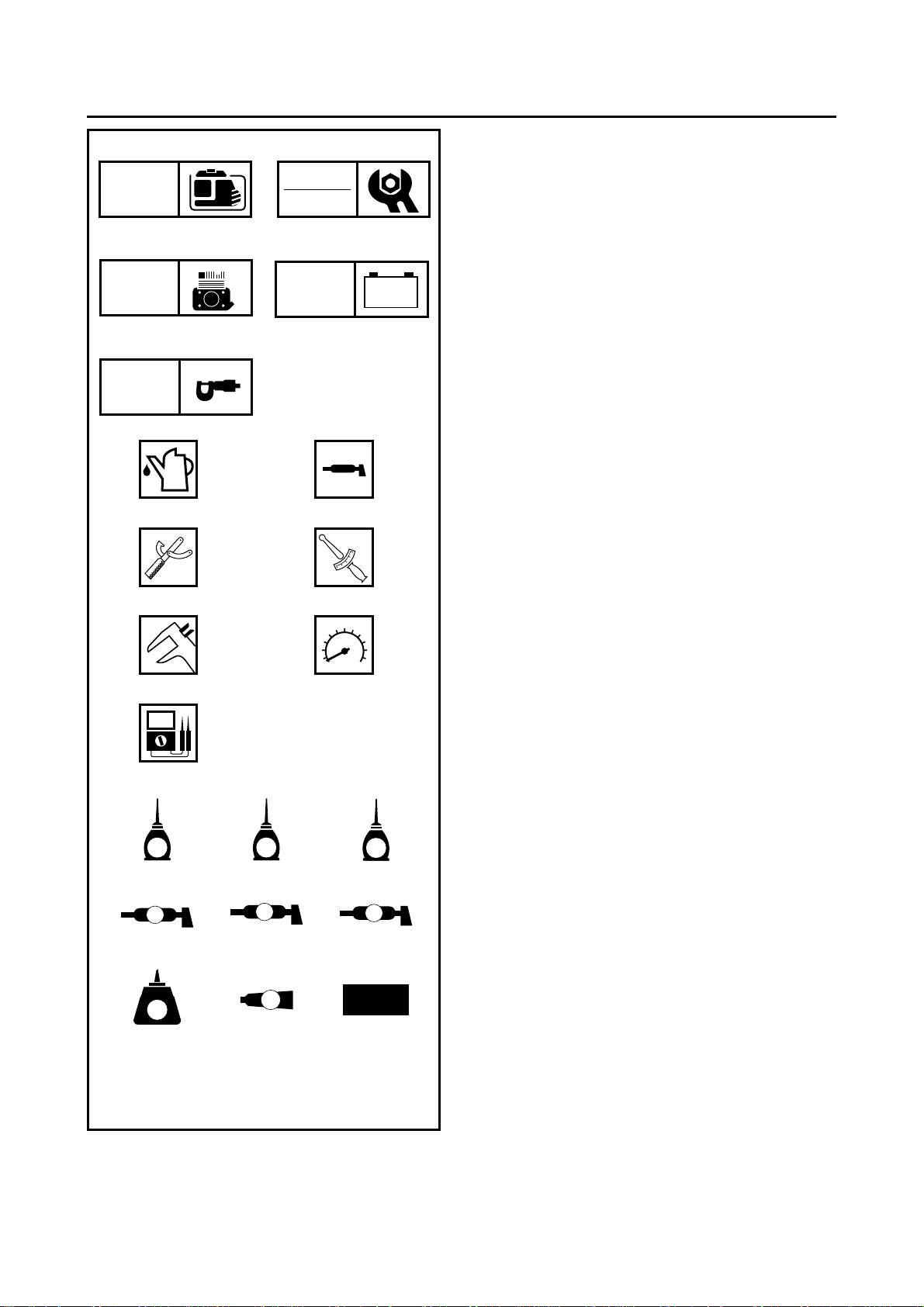
ILLUSTRATED SYMBOLS
(Refer to the illustration)
Illustrated symbols 1 through 5 are designed
as thumb tabs to indicate the chapter’s number
and content.
General information
1
Periodic inspections and adjustments
2
Engine
3
Electrical
4
Specifications
5
67
89
T
.
R
.
0A
B
CDE
E
G
M
FGH
B
LS
M
IJK
LT
4
New
Illustrated symbols 6 through B are used to
identify the specific tools and test equipment.
Filling fluid
6
Lubricant
7
Special tool
8
Tightening
9
Wear limit, clearance
0
Engine speed
A
, V, A
Ω
B
Illustrated symbols C through K in the
exploded diagram indicate the grades of lubricant and the locations of the lubrication points.
Apply engine oil
C
Apply gear oil
D
Apply molybdenum disulfide oil
E
Apply wheel bearing grease
F
Apply lightweight lithium-soap base grease
G
Apply molybdenum disulfide grease
H
Apply a locking agent (LOCTITE
I
Apply Yamaha bond
J
Use a new one
K
®
)
INDEX
GENERAL INFORMATION
PERIODIC INSPECTIONS
AND ADJUSTMENTS
ENGINE
ELECTRICAL
SPECIFICATIONS
GEN
INFO
INSP
ADJ
ENG
–+
ELEC
SPEC
1
2
3
4
5

CHAPTER 1.
GENERAL INFORMATION
PILOT LIGHT .....................................2-13
RECEPTACLE ...................................2-14
MACHINE IDENTIFICATION
SERIAL NUMBER ............................... 1-1
STARTING SERIAL NUMBER ............1-1
IMPORTANT INFORMATION
PREPARATION FOR REMOVAL AND
DISASSEMBLY ...................................1-2
CAUTION ON SERVICE .....................1-2
NOTES ON SERVICE .........................1-2
ALL REPLACEMENT PARTS ............. 1-3
GASKETS, OIL SEALS,
AND O-RINGS .................................... 1-3
BEARINGS AND OIL SEALS ..............1-3
SPECIAL TOOLS AND TESTERS
...................1-1
..................1-2
...........1-4
CHAPTER 2.
PERIODIC INSPECTIONS
AND ADJUSTMENTS
INTRODUCTION
......................................2-1
CHAPTER 3.
ENGINE
CONTROL PANEL
CONTROL BOX COVER
AND FUEL TANK
MUFFLER AND AIR CLEANER
BREATHER HOSE INSTALLATION ...3-5
MUFFLER ASSEMBLY .......................3-5
CONTROL UNIT AND AC-CDI UNIT
ENGINE
CYLINDER HEAD COVER AND CYLINDER
HEAD
.....................................................3-7
........................................................3-8
PUSH ROD INSPECTION .................3-10
CYLINDER HEAD INSPECTION .......3-10
CYLINDER HEAD ASSEMBLY .........3-11
BREATHER HOSE ASSEMBLY ........3-11
...................................3-1
.....................................3-3
...............3-4
.......3-6
PERIODIC MAINTENANCE/LUBRICATION
INTERVALS
ENGINE
ENGINE OIL LEAKAGE
CHECKING .........................................2-2
OIL LEVEL CHECKING ...................... 2-2
OIL REPLACEMENT ...........................2-3
FUEL LEAKAGE ................................. 2-4
FUEL COCK STRAINER
INSPECTION ......................................2-4
FUEL TANK FILTER ...........................2-5
AIR FILTER ELEMENT ....................... 2-6
MUFFLER ...........................................2-7
VALVE CLEARANCE
ADJUSTMENT .................................... 2-8
COMPRESSION PRESSURE ........... 2-10
RATED ENGINE SPEED ..................2-11
BREATHER HOSE ............................2-11
ELECTRICAL
SPARK PLUG ...................................2-12
ENGINE SWITCH .............................2-13
ECONOMY SWITCH .........................2-13
..............................................2-1
....................................................2-2
.........................................2-12
VALVE
RECOIL STARTER
GENERATOR
....................................................3-12
VALVE AND VALVE SPRING
REMOVAL .........................................3-13
VALVE AND VALVE SPRING
INSPECTION .....................................3-13
ROCKER ARM INSPECTION ...........3-14
VALVE SEAT INSPECTION ..............3-15
VALVE LAPPING ...............................3-16
VALVE AND VALVE SPRING
ASSEMBLY .......................................3-17
.................................3-18
RECOIL STARTER
DISASSEMBLY .................................3-20
RECOIL STARTER INSPECTION .....3-20
RECOIL STARTER ASSEMBLY .......3-21
.........................................3-23
MAGNETO ROTOR AND STATOR COIL
ASSEMBLY REMOVAL .....................3-25
MAGNETO ROTOR AND STATOR COIL
ASSEMBLY INSTALLATION .............3-26

CRANKCASE COVER
AND CAMSHAFT ...................................3-28
CAMSHAFT INSPECTION ................3-29
VALVE LIFTER INSPECTION ..........3-30
CAMSHAFT ASSEMBLY ..................3-30
CRANKCASE COVER
INSPECTION ....................................3-30
CRANKCASE COVER
INSTALLATION .................................3-30
PISTON, CONNECTING ROD, CRANK-
SHAFT AND CRANKCASE ...................3-31
CRANKCASE (CYLINDER)
INSPECTION ....................................3-32
PISTON AND PISTON
PIN INSPECTION .............................3-32
PISTON RING INSPECTION ............ 3-34
CRANKSHAFT INSPECTION ........... 3-34
CONNECTING ROD OIL
CLEARANCE INSPECTION .............3-35
PISTON RING
AND PISTON ASSEMBLY ................3-36
CRANKSHAFT ASSEMBLY ..............3-37
CHAPTER 5.
SPECIFICATIONS
GENERAL SPECIFICATIONS ..................5-1
MAINTENANCE SPECIFICATIONS .........5-3
ENGINE ...............................................5-3
GENERATOR AND ELECTRICAL ......5-6
TIGHTENING TORQUE ............................5-7
GENERAL TORQUE
SPECIFICATIONS ....................................5-8
DEFINITION OF UNITS ............................5-8
WIRE ROUTING DIAGRAM .....................5-9
CONTROL BOX PANEL AND BEHIND
CONTROL BOX ...................................5-9
ENGINE AND GENERATOR .............5-10
CARBURETOR ......................................3-38
FLOAT HEIGHT INSPECTION .........3-40
CHOKE CABLE INSTALLATION ......3-41
THROTTLE CONTROL MOTOR ......3-41
TROUBLESHOOTING ...........................3-42
ENGINE .............................................3-42
THROTTLE CONTROL SYSTEM .....3-48
CHAPTER 4.
ELECTRICAL
ELECTRICAL COMPONENTS ................4-1
CIRCUIT DIAGRAM .................................4-2
SWITCHES ............................................... 4-3
CHECKING SWITCH CONTINUITY ...4-3
IGNITION SYSTEM ..................................4-4
TROUBLESHOOTING CHART ...........4-4
GENERATOR SYSTEM ........................... 4-9
TROUBLESHOOTING CHART ...........4-9
MACHINE IDENTIFICATION
GENERAL INFORMATION
MACHINE IDENTIFICATION
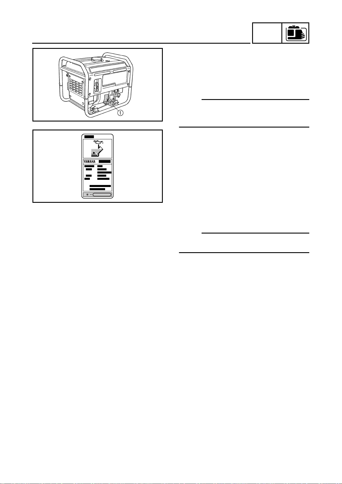
SERIAL NUMBER
The serial number is printed on a label
which is affixed to the generator as shown.
NOTE:
The first three characters of this number are
SVU1010H
for model identification, the remaining digits
are the unit production number.
GEN
INFO
1
SVU1020H
STARTING SERIAL NUMBER
7VU-300101~
NOTE:
Designs and specifications are subject to
change without notice.
1-1
SVU1030H
SVU1040H
SVU1050H
GEN
IMPORTANT INFORMATION
IMPORTANT INFORMATION
PREPARATION FOR REMOVAL AND DISASSEMBLY
CAUTION ON SERVICE
Fire prevention
When servicing the engine, always keep the engine and yourself
away from fire.
NOTES ON SERVICE
1. Correct tools
Be sure to use the correct special tool for the job to guard
against damage.
2. Oil, grease and seals
Be sure to use genuine Yamaha oils, grease and sealers, or the
equivalents.
INFO
1
SVU1060H
SVU1070H
SVU1080H
3. Expendable parts
Always replace the gaskets, O-rings, cotter pins and circlips with
new parts when servicing engine.
4. Tightening torque
Be sure to follow torque specifications. When tightening bolts,
nuts or screws, start with the largest-diameter fastener and work
from an inner position to an outer position in a crisscross pattern.
5. Notes on disassembly and assembly
a. Parts should be cleaned in solvent and blown dry with com-
pressed air after disassembly.
SVU1090H
SVU1100H
b. Contact surfaces of moving parts should be oiled when reas-
sembled.
c. Make sure that the parts, move smoothly after each section of
the machine is assembled.
1-2
SVU1110H
GEN
IMPORTANT INFORMATION
ALL REPLACEMENT PARTS
We recommend the use of genuine Yamaha parts for all replacements. Use oil and/or grease, recommended by Yamaha, for
assembly and adjustment.
GASKETS, OIL SEALS, AND O-RINGS
1. All gaskets, seals, and O-rings should be replaced when an
engine is overhauled. All gaskets surfaces, oil seal lips, and Orings must be cleaned.
2. Properly oil all mating parts and bearings during reassembly.
Apply grease to the oil seal lips.
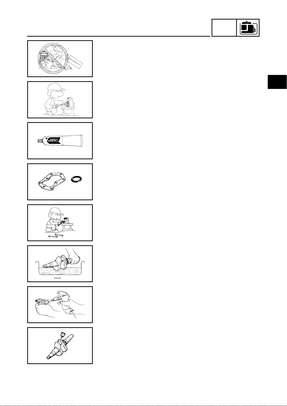
BEARINGS AND OIL SEALS
Install the bearing(s) 1 and oil seal(s) 2 with their manufacture’s
marks or numbers facing outward. (In other words, the stamped letters must be on the side exposed to view.) When installing oil
seal(s), apply a light coating of light-weight lithium base grease to
the seal lip(s). Oil the bearings liberally when installing.
INFO
SVU1120H
CAUTION:
Do not use compressed air to spin the bearings dry. This
causes damage to the bearing surfaces.
1-3
SVU1130H
SVU1140H
GEN
SPECIAL TOOLS AND TESTERS
SPECIAL TOOLS AND TESTERS
The proper special tools are necessary for complete and accurate
tune-up and assembly. Using the correct special tool will help prevent damage caused by the use of improper tools or improvised
techniques.
1. Piston ring compressor
P/N. 90890-05158
This tool is used to compress the piston rings when installing the
piston.
2. Valve spring compressor
P/N. 90890-01253
This tool is used to remove the valve springs.
INFO
SVU1150H
SVU1160H
SVU1170H
SVU1180H
3. Thickness gauge
P/N. 90890-03079
This gauge is used to adjust valve clearance, piston clearance
and piston ring end gap.
4. Cylinder gauge
Commercially obtainable
This instrument is used for checking cylinder bore size and condition.
5. Engine tachometer
P/N. 90890-03113
This instrument is used for reading engine r/min.
6. Compression gauge 1
P/N. 90890-03081
Adapter 2
P/N. 90890-04082
This gauge is used for checking engine compression.
SVU1190H
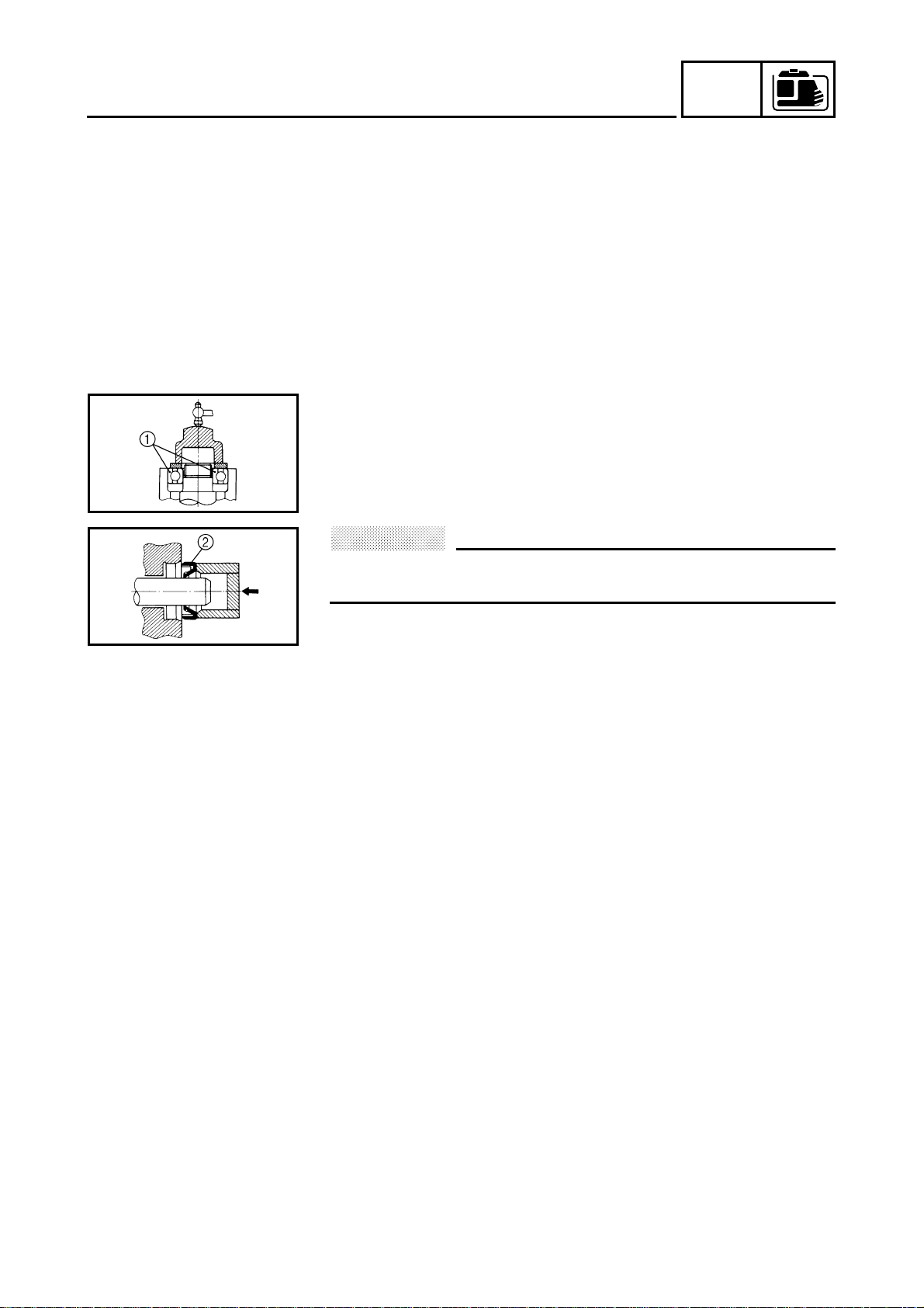
7. Dial gauge
P/N. 90890-03097
This instrument is used for checking crankshaft side clearance.
1-4
SVU1200H
SVU1210H
SVU1220H
SPECIAL TOOLS AND TESTERS
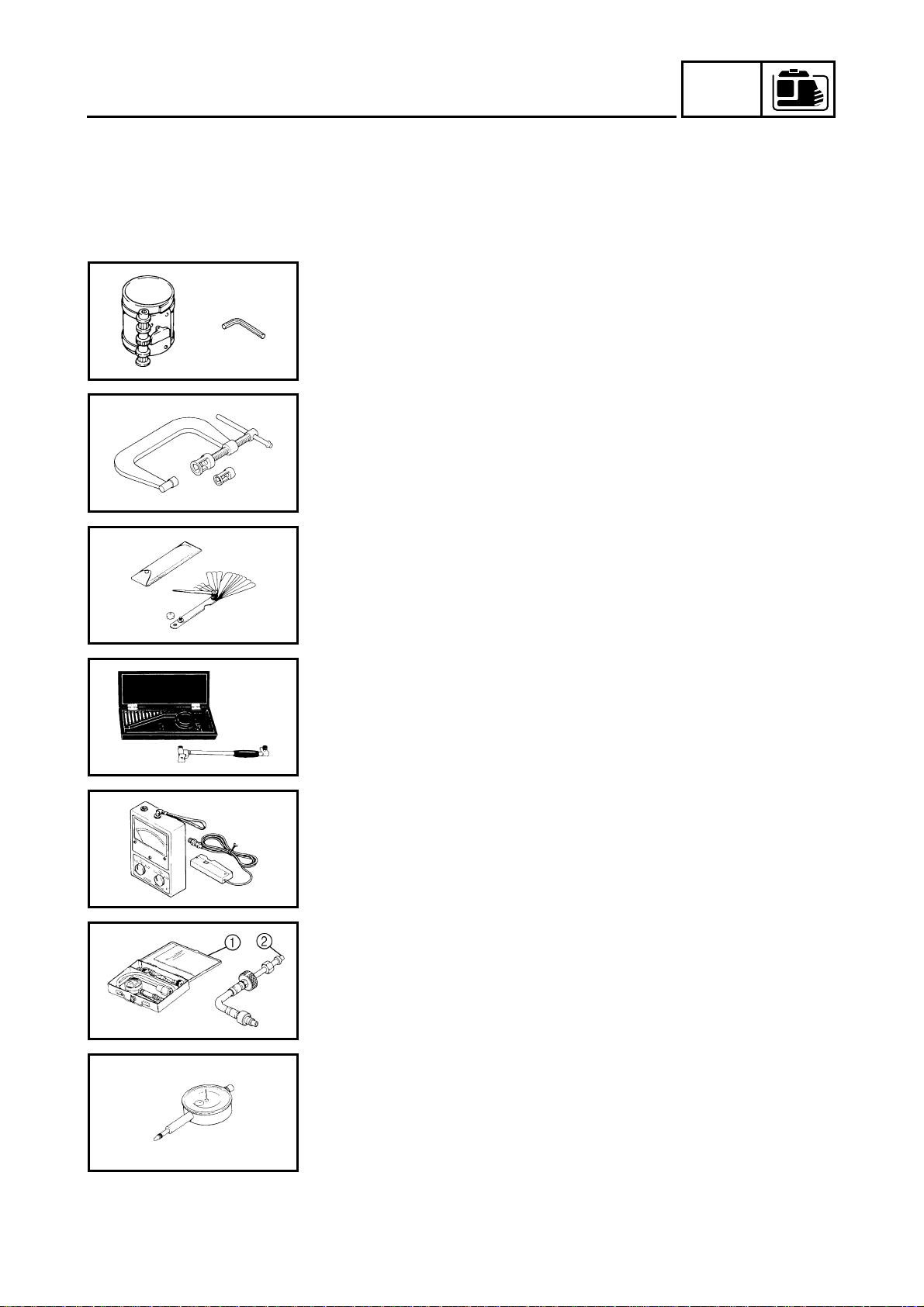
8. Piston pin puller
P/N. 90890-01304
This tool is used to remove the piston pin.
9. Sheave holder
P/N. 90890-01701
This tool is necessary for holding the flywheel.
10.Rotor puller
P/N. 90890-01362
This tool is necessary for removing the flywheel.
GEN
INFO
SVU1230H
SVU1240H
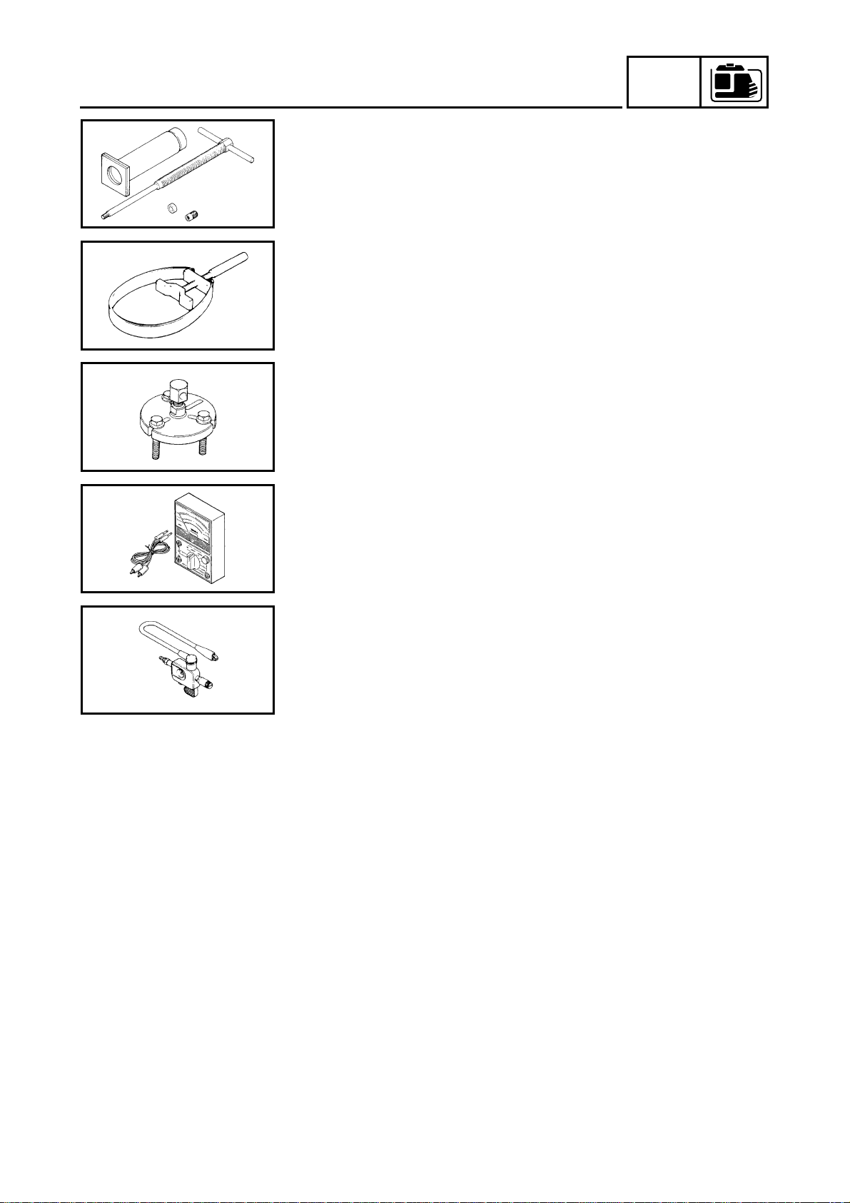
11.Pocket tester
P/N. 90890-03112
This instrument is necessary for checking the electrical system.
12.Ignition checker
P/N. 90890-06754
This instrument is necessary for checking the ignition system
components.
1-5
INSP
ADJ
INTRODUCTION/PERIODIC MAINTENANCE/
LUBRICATION INTERVALS
PERIODIC INSPECTIONS AND ADJUSTMENTS
INTRODUCTION
This chapter includes all information necessary to perform recommended inspections and adjustments. These preventive maintenance procedures, if followed, will ensure more reliable machine
operation and a longer service life. The need for costly overhaul work will be greatly reduced. This
information applies to machines already in service as well as new machines that are being prepared
for sale. All service technicians should be familiar with this entire chapter.
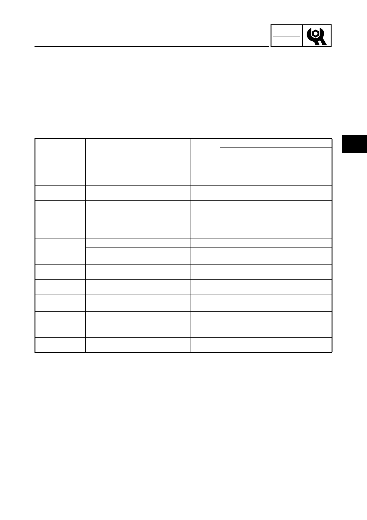
PERIODIC MAINTENANCE/LUBRICATION INTERVALS
Item Remarks
Spark plug
Valve clearance Check and adjust when engine is cold.
Crankcase breather
system
Idle speed Check and adjust engine idle speed.
Exhaust system
Engine oil
Air filter Clean. Replace if necessary.
Fuel filter
Fuel line
Choke knob Check choke operation.
Cooling system Check for fan damage.
Starting system Check recoil starter operation.
Decarbonization More frequently if necessary.
Generation Check the pilot light comes on.
Fittings/fasteners
Check condition, adjust gap and clean.
Replace if necessary.
Check breather hose for cracks or damage.
Replace if necessary.
Check for leakage.
Retighten or replace gasket if necessary.
Check muffler screen and spark arrester.
Clean/replace if necessary.
Check oil level.
Replace.
Clean fuel cock and fuel tank filter.
Replace if necessary.
Check fuel hose for cracks or damage.
Replace if necessary.
Check all fittings and fasteners.
Correct if necessary.
Pre-Opera-
tion check
(daily)
●
●
●
●
●
●
Initial Every
1 month or
20 Hr
●●
3 months
or 50 Hr
●
●
6 months
or 100 Hr
●
●
12 months
or 300 Hr
●
●
●
●
●
●
2
2-1
INSP
ADJ
SVU2010H
ENGINE OIL LEAKAGE CHECKING/
OIL LEVEL CHECKING
ENGINE
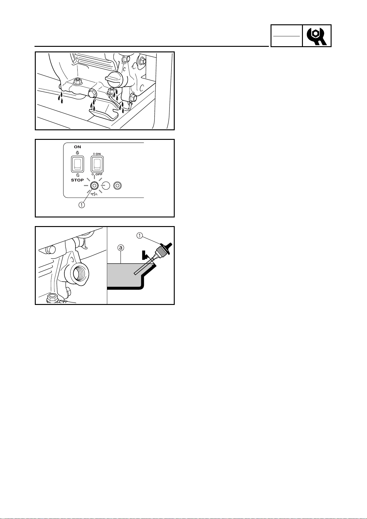
ENGINE OIL LEAKAGE CHECKING
1. Check the areas outside of the engine for
oil leakage.
Oil leakage → Replace the gasket, oil
seal, or O-ring.
SVU2020H
ECON.
SW
OIL LEVEL CHECKING
1. Check:
• Oil level with oil warning light 1
Check whether the oil warning light
flashes by operating the recoil starter.
Oil warning light flashes → Add oil.
OVER
AC
LOAD
Oil warning light does not flash → OK
2. Remove:
• Oil filler cap
1
3. Check:
• Check that the engine oil is at the spec-
ified level a.
Oil level checking steps:
• Place the engine on a level surface.
SVU2030H
• Warm up the engine for several minutes.
• Stop the engine.
• Check that the engine oil is at the specified
level a. Add oil if necessary.
4. Install:
• Oil filler cap
2-2
INSP
ADJ
SVU2040H
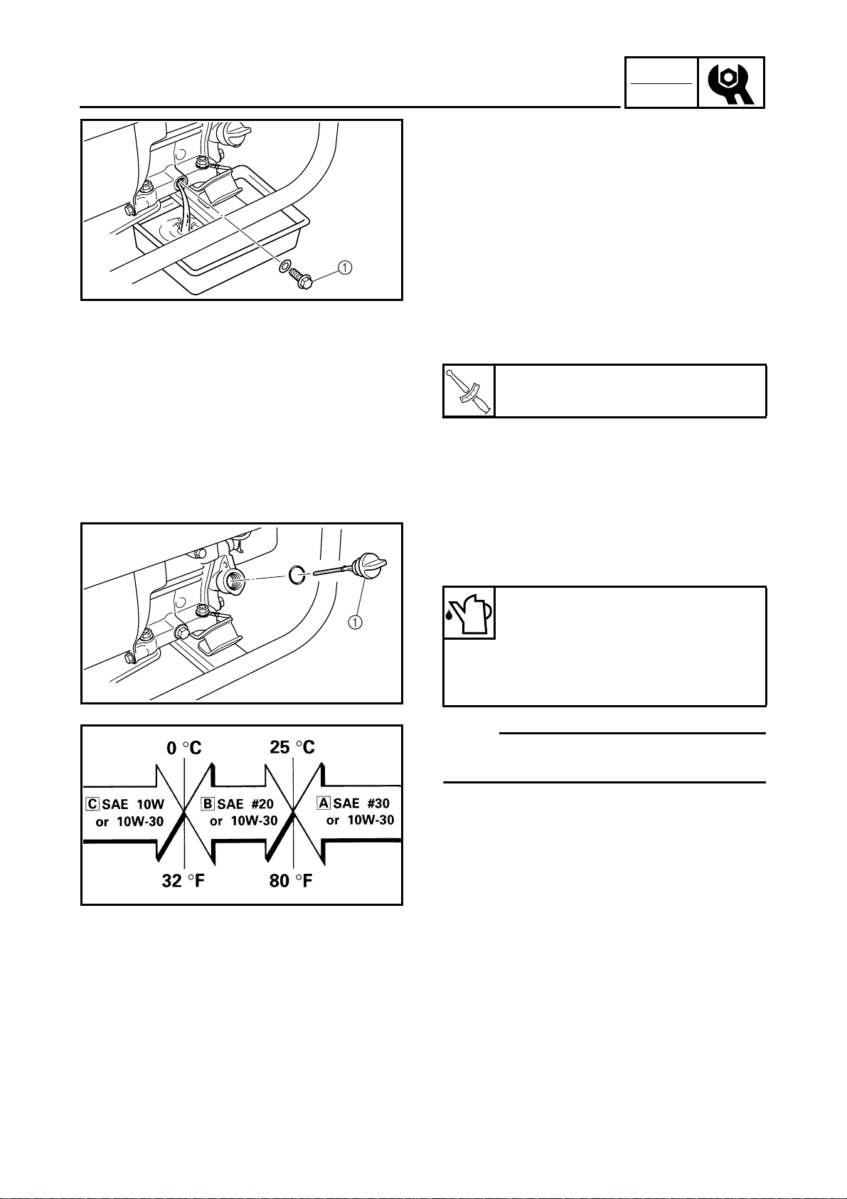
OIL REPLACEMENT
OIL REPLACEMENT
1. Warm up the engine for several minutes.
2. Stop the engine.
3. Place a receptacle under the engine.
4. Remove:
• Oil drain bolt
5. Tilt the engine to drain the oil completely.
6. Tighten:
• Oil drain bolt
Oil drain bolt:
17 Nm (1.7 m · kg, 12 ft · lb)
T
.
R
.
1
1
SVU2050H
SVU2060H
7. Remove:
• Oil filler cap
1
8. Fill:
Recommended oil:
È SAE #30 or 10W-30
É SAE #20 or 10W-30
Ê SAE 10W or 10W-30
Engine oil quantity:
0.6 L (0.53 Imp qt, 0.63 US qt)
NOTE:
Recommended engine oil classification:
API Service “SE” or “SF”, if not available, “SD”.
9. Install:
• Oil filler cap
2-3
INSP
ADJ
FUEL LEAKAGE/
FUEL COCK STRAINER INSPECTION
FUEL LEAKAGE
1. Check:
• Leakage
Check at fuel tank, fuel cock, fuel hose,
and carburetor.
CAUTION:
Replace hose every four years.
SVU2070H
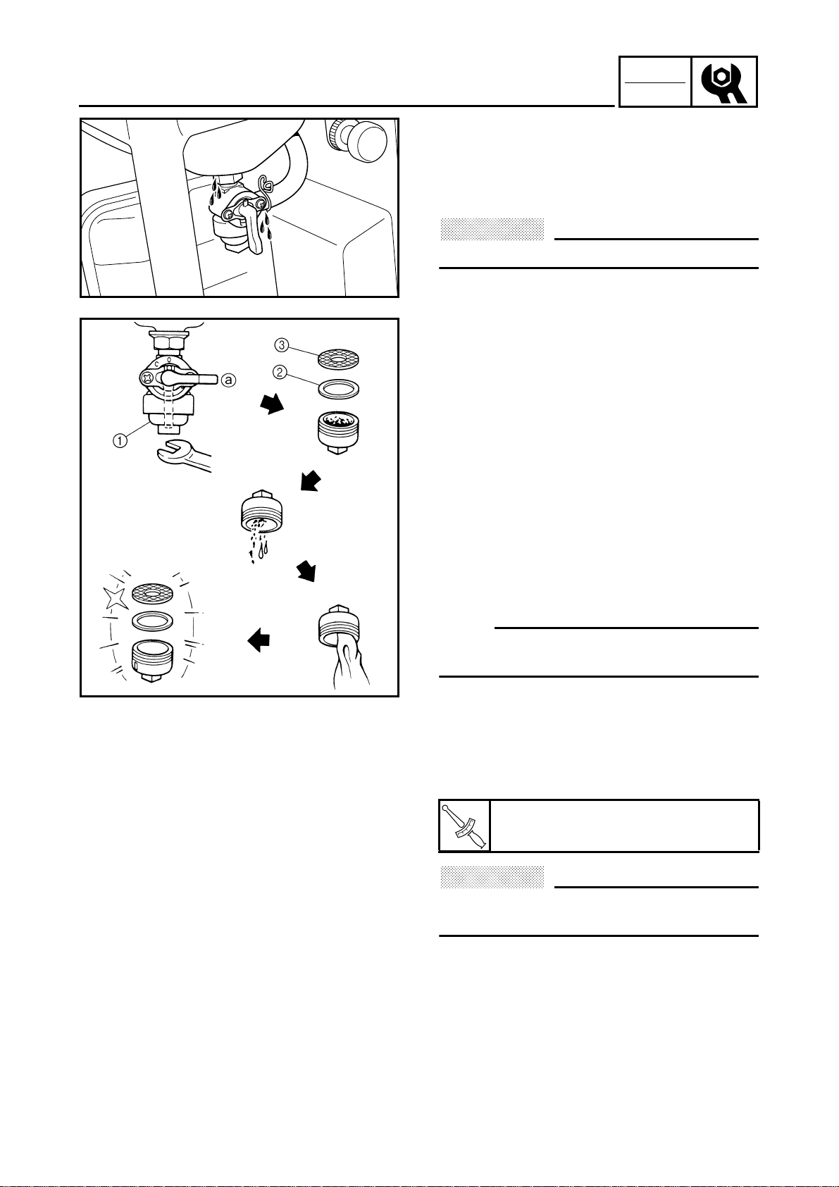
FUEL COCK STRAINER INSPECTION
1. Turn the fuel cock to the “OFF” a position, detach the strainer cup, and then
remove the debris from inside the cup.
2. Remove:
• Fuel cock cup 1
•Gasket 2
• Strainer 3
3. Inspect:
• Fuel cock cup
Dirt/debris → Clean.
•Gasket 2
Damage → Replace.
• Strainer 3
Dirt/debris→ Clean.
SVU2080H
NOTE:
Clean the cup with solvent, and then dry it
thoroughly.
4. Install:
• Strainer
•Gasket
• Fuel cock cup
Fuel cock cup:
1.3 Nm (0.13 m · kg, 0.94 ft · lb)
T
.
R
.
CAUTION:
Securely install the strainer cup to prevent
fuel leaks.
2-4
INSP
ADJ
FUEL TANK FILTER
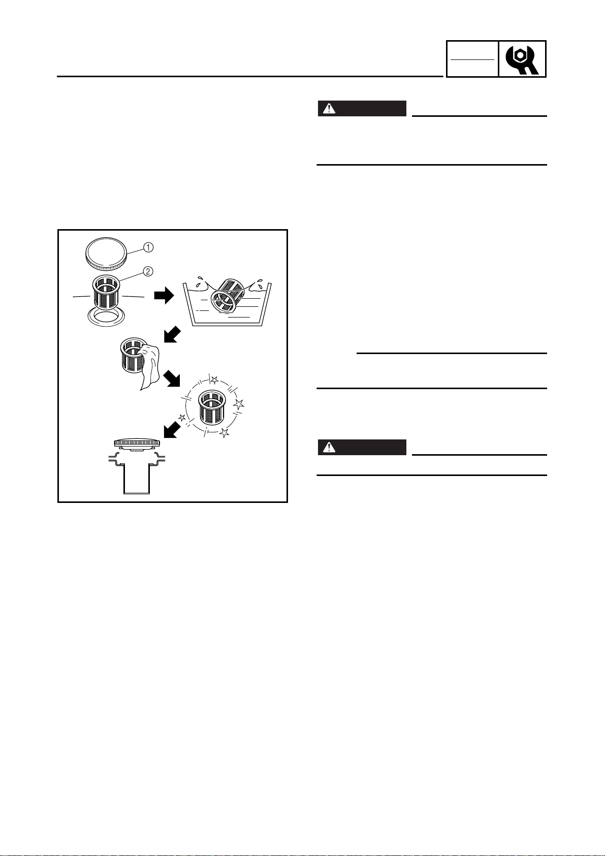
FUEL TANK FILTER
WARNING
Do not smoke, and keep away from open
flames, sparks, or any other source of fire
when handling or in the vicinity of fuel.
1. Remove:
• Fuel tank cap 1
• Fuel tank filter 2
2. Inspect:
• Fuel tank filter
Damage → Replace.
3. Clean:
• Fuel tank filter
NOTE:
Clean the fuel tank filter with solvent, and then
dry it thoroughly.
SVU2090H
4. Install:
• Fuel tank filter
• Fuel tank cap
WARNING
Be sure the tank cap is tightened securely.
2-5
INSP
ADJ
SVU2100H
SVU2110H
AIR FILTER ELEMENT
AIR FILTER ELEMENT
1. Remove:
•Screws 1
• Air filter case cover 2
2. Remove:
• Air filter element 1
SVU2120H
3. Inspect:
• Element
Damage → Replace.
Clogging → Wash the element in a solvent, and then dry it thoroughly.
Oil the element and squeeze out the
excess oil.
CAUTION:
• Do not wring out the element: this could
cause it to tear.
• Do not wash the element in gasoline or in
acidic, alkalinic, or organic solvents.
4. Install:
• Air filter element
• Air filter case cover
•Screws
CAUTION:
The engine should never run without the
element, otherwise excessive piston and/or
cylinder wear may result.
2-6

INSP
ADJ
SVU2130H
SVU2140H
MUFFLER
MUFFLER
1. Remove:
• Muffler
Refer to “MUFFLER AND AIR
CLEANER” in CHAPTER 3.
• Muffler band 1
• Muffler cap 2
• Washer 3
• Muffler screen 4
2. Decarbonize:
• Muffler
Tap on the muffler in the area shown in
the illustration to loosen carbon buildup,
and then shake it out of the end of the
muffler.
CAUTION:
Don’t use a wire to clean, otherwise the
noise damping material may come out, and
the damping effect may be reduced.
SVU2150H
3. Decarbonize:
• Muffler screen
4. Install:
• Muffler screen
• Muffler cap
• Muffler band
• Muffler
Refer to “MUFFLER AND AIR
CLEANER” in CHAPTER 3.
2-7
INSP
ADJ
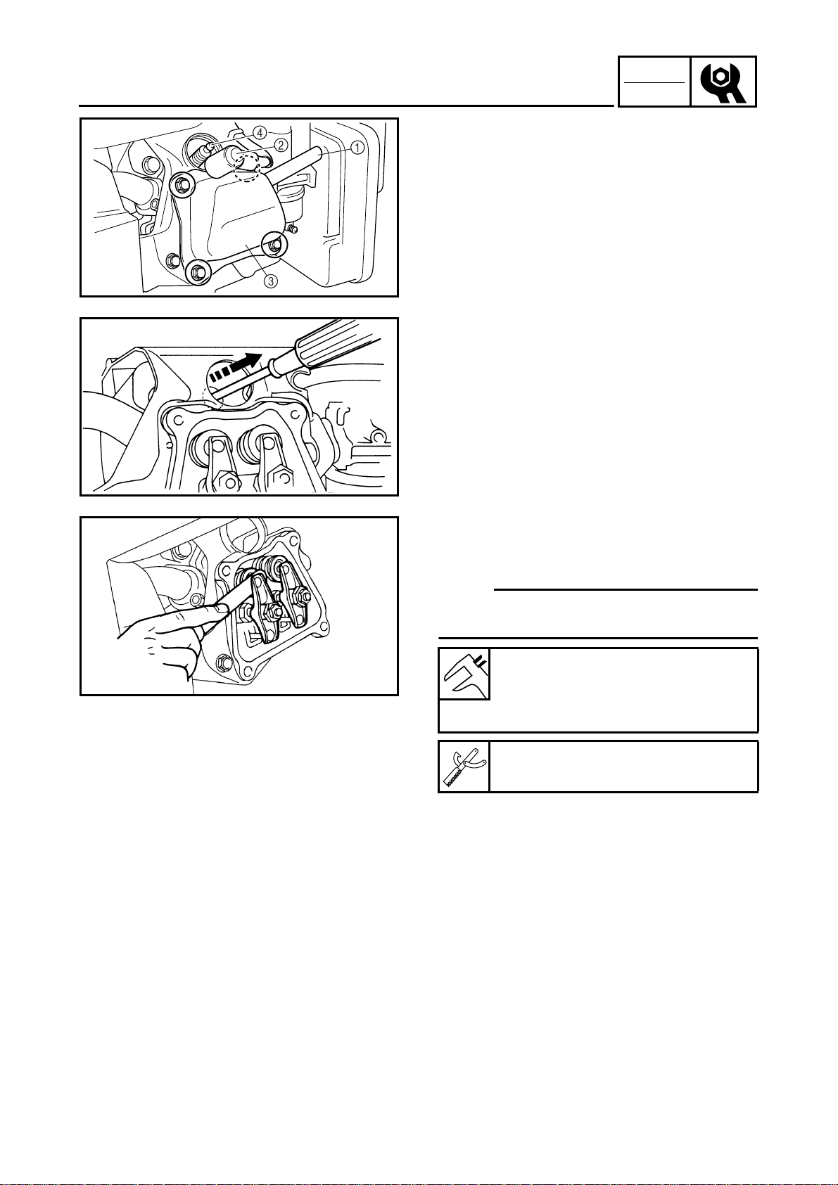
VALVE CLEARANCE ADJUSTMENT
VALVE CLEARANCE ADJUSTMENT
1. Remove:
• Breather hose 1
• Spark plug cap 2
• Cylinder head cover 3
• Spark plug 4
SVU2160H
SVU2170H
SVU2180H
2. Gently operate the starter rope to bring
the piston to the top-dead-center of its
compression stroke (when the screwdriver inserted into the spark plug hole
reaches the highest position).
3. Measure:
• Valve clearance
Out of specification → Adjust.
NOTE:
Valve clearance must be measured when the
engine is cool to the touch.
Intake valve (cold):
0.1 mm (0.004 in)
Exhaust valve (cold):
0.1 mm (0.004 in)
Thickness gauge:
90890-03079
2-8
INSP
ADJ
VALVE CLEARANCE ADJUSTMENT
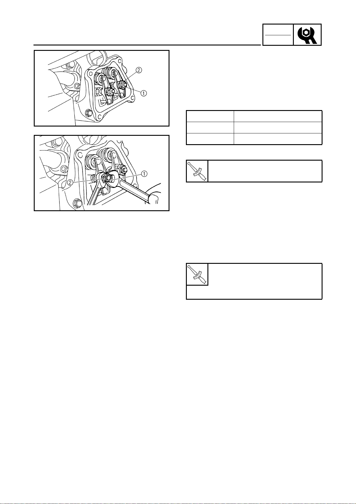
4. Adjust:
• Valve clearance
Adjustment steps:
• Loosen the locknut 1.
• Turn the adjuster 2 in or out to obtain the
proper clearance.
SVU2190H
SVU2200H
Adjuster Valve clearance
Turn in Decrease
Turn out Increase
• Tighten the locknut 1.
Locknut:
10 Nm (1.0 m · kg, 7.2 ft · lb)
T
.
R
.
5. Install:
• Cylinder head cover
• Breather hose
• Spark plug
• Spark plug cap
Cylinder head cover bolt:
10 Nm (1.0 m · kg, 7.2 ft · lb)
T
.
R
.
Spark plug:
18 Nm (1.8 m · kg, 13 ft · lb)
2-9
INSP
ADJ
COMPRESSION PRESSURE
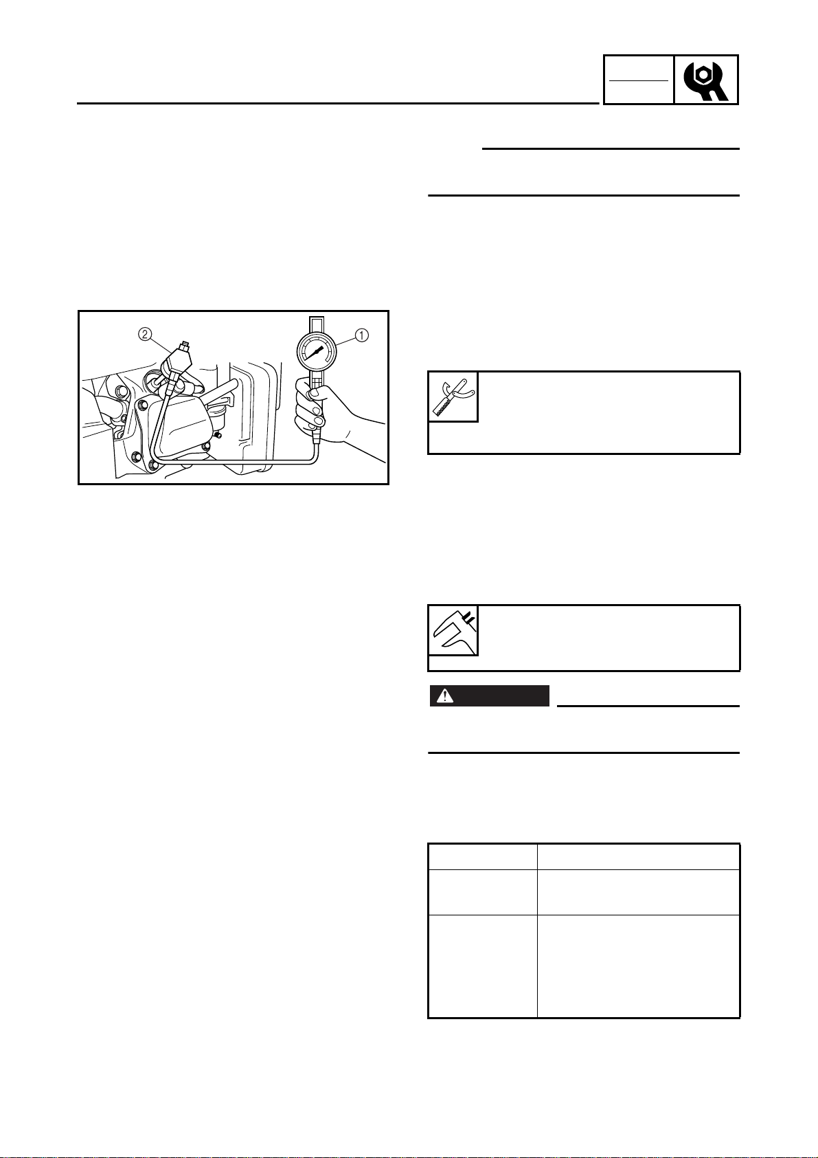
COMPRESSION PRESSURE
NOTE:
Measure the compression after checking and
adjusting the valve clearance.
1. Warm up the engine for several minutes.
2. Remove:
• Spark plug
3. Connect:
• Compression gauge 1
• Adapter 2
Compression gauge:
90890-03081
Adapter:
90890-04082
SVU2210H
4. Measure:
• Compression
To measure the compression, pull the
recoil starter until the needle stops rising on the compression gauge.
Standard compression pressure:
400 ~ 600 kPa
(4 ~ 6 kg/cm
2
, 57 ~ 85 psi)
WARNING
To prevent sparking when cranking the
engine, ground the high-tension cord.
Testing steps (below minimum level):
• Squirt a few drops of oil into the cylinder.
• Measure the compression again.
Reading Diagnosis
If higher than
without oil
• Worn cylinder, piston, and
piston ring
If the same as
without oil
2-10
• Defective piston, ring(s),
valve(s), and cylinder
head gasket
• Improper valve timing and
valve clearance
INSP
ADJ
COMPRESSION PRESSURE/
RATED ENGINE SPEED/BREATHER HOSE
Testing steps (above maximum level):
• Check the cylinder head, valve surfaces,
and piston crown for carbon deposits.
5. Install:
• Spark plug
Spark plug:
18 Nm (1.8 m · kg, 13 ft · lb)
T
.
R
.
SVU2220H
SVU2230H
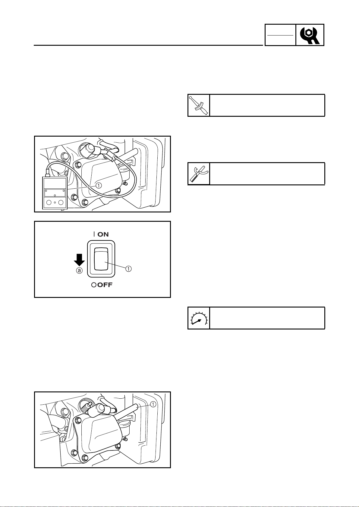
RATED ENGINE SPEED
1. Connect:
• Engine tachometer
1
Engine tachometer:
90890-03113
2. Inspect:
• Rated engine speed
Specified engine speed → OK
Out of specification → Refer to “TROUBLESHOOTING” in CHAPTER 3.
Inspection steps:
• Operate the engine (with no load).
• Turn economy switch 1 to “OFF” a.
• Measure the rated engine speed.
SVU2240H
Rated engine speed:
3,550 r/min
BREATHER HOSE
1. Inspect:
• Breather hose 1
Cracks/damage → Replace.
Poor connection → Correct.
2-11
INSP
ADJ
SPARK PLUG
ELECTRICAL
SPARK PLUG
WARNING
Inspect and adjust the areas around the
cylinder head after the engine has cooled
down completely.
CAUTION:
Before removing the spark plug, use compressed air to clean the cylinder head
cover to prevent dirt from falling into the
engine.
1. Remove:
• Spark plug cap
• Spark plug
SVU2250H
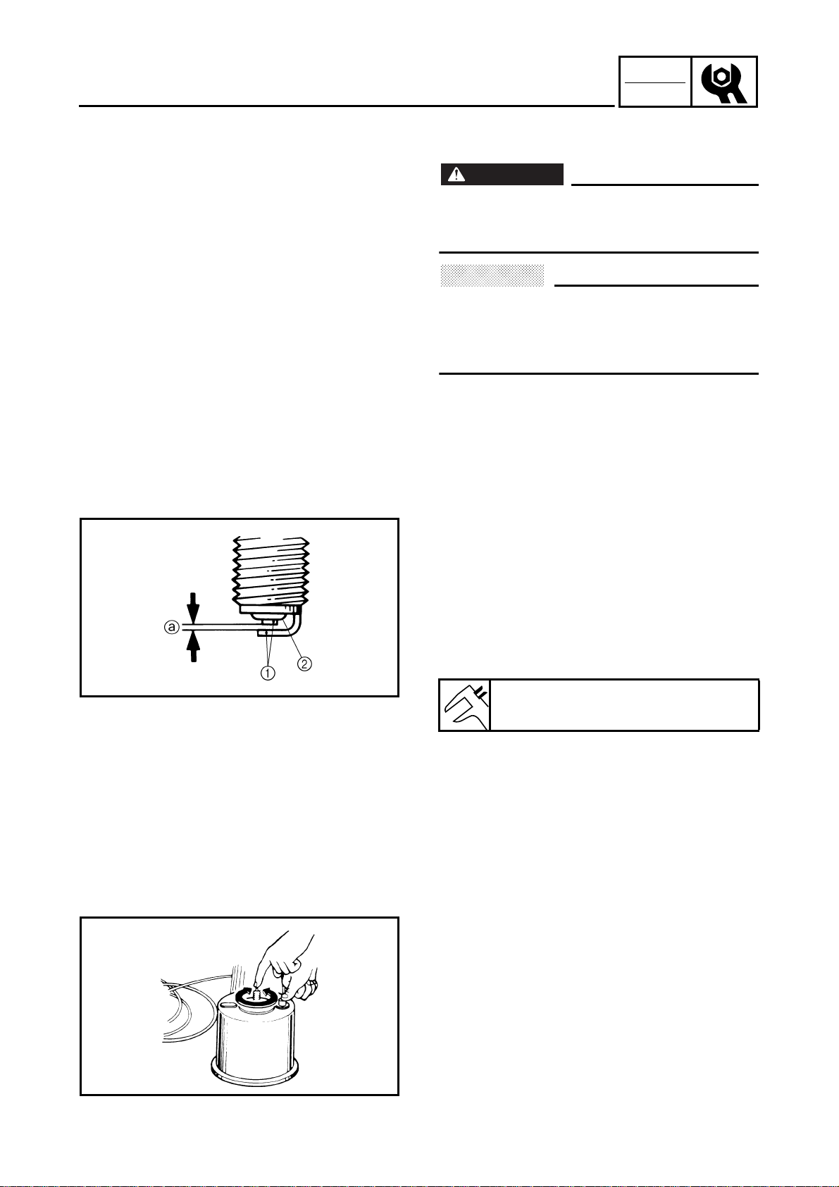
2. Inspect:
•Electrode 1
Wear/damage → Replace.
• Insulator color 2
3. Measure:
• Spark plug gap a
Use a wire gauge or thickness gauge.
Out of specification → Regap.
Spark plug gap:
0.7 ~ 0.8 mm (0.028 ~ 0.031 in)
If necessary, clean the spark plug with a spark
plug cleaner.
Standard spark plug (with resistor):
BPR4ES (NGK)
Before installing the spark plug, clean the gasket surface and plug surface.
SVU2260H
2-12
INSP
ADJ
SPARK PLUG/ENGINE SWITCH/
ECONOMY SWITCH/PILOT LIGHT
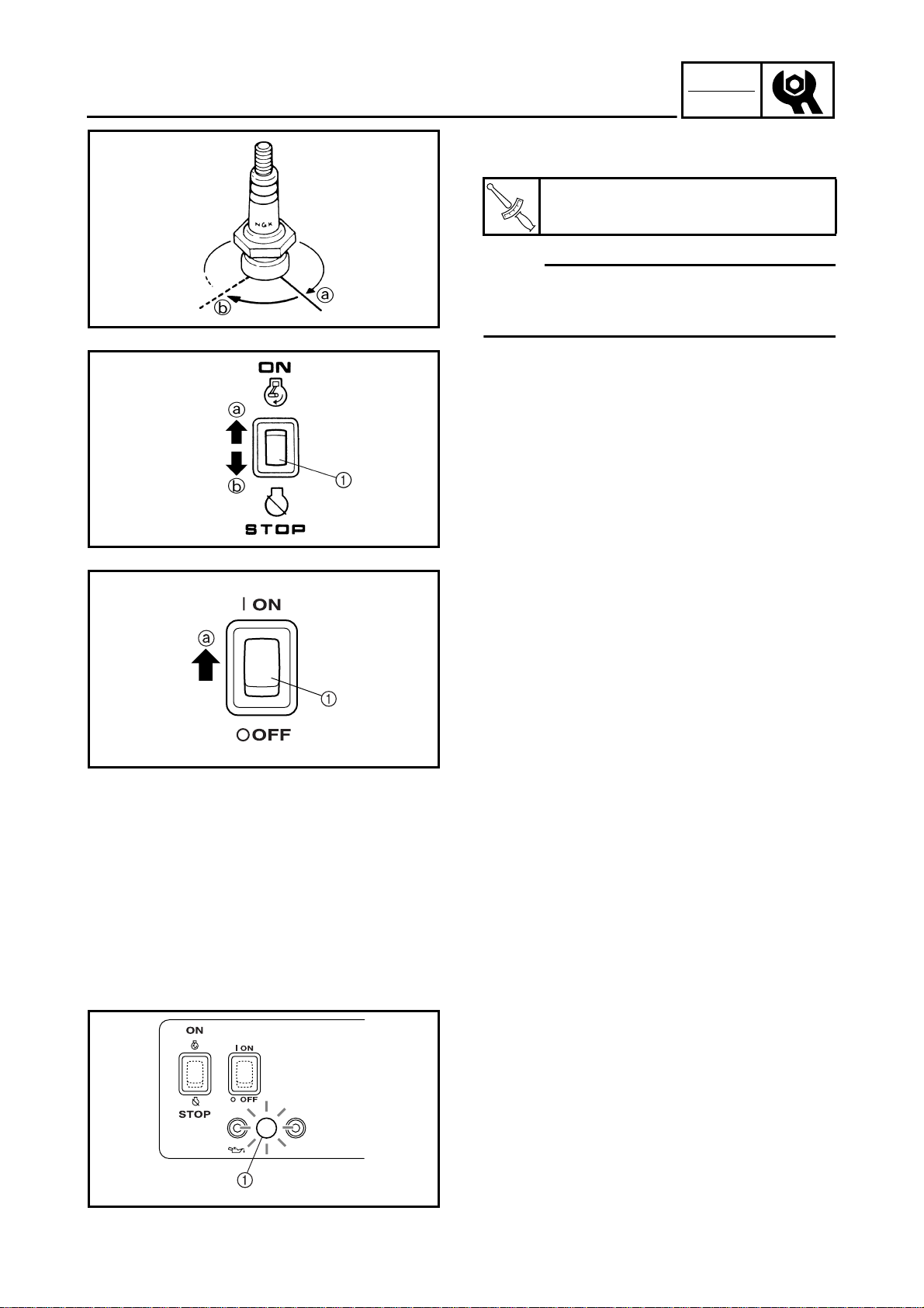
4. Tighten:
• Spark plug
Spark plug:
18 Nm (1.8 m · kg, 13 ft · lb)
T
.
R
.
NOTE:
To prevent thread damage, finger tighten
SVU2270H
SVU2280H
the spark plug before tightening it to the specified torque b.
ENGINE SWITCH
1. Check:
• Engine switch 1
Checking steps:
• Set the engine switch 1 to “ON” a.
• Start the engine.
• Check that the engine stops when the
switch is set to “STOP” b.
a
ECON.
SW
SVU2290H
ECONOMY SWITCH
1. Check:
• Economy switch 1
Checking steps:
• Set the economy switch 1 to “ON” a.
• Start the engine.
• Turn the switch of the electric device connected to the AC outlet “ON” and “OFF” to
check whether the engine speed increases
and decreases.
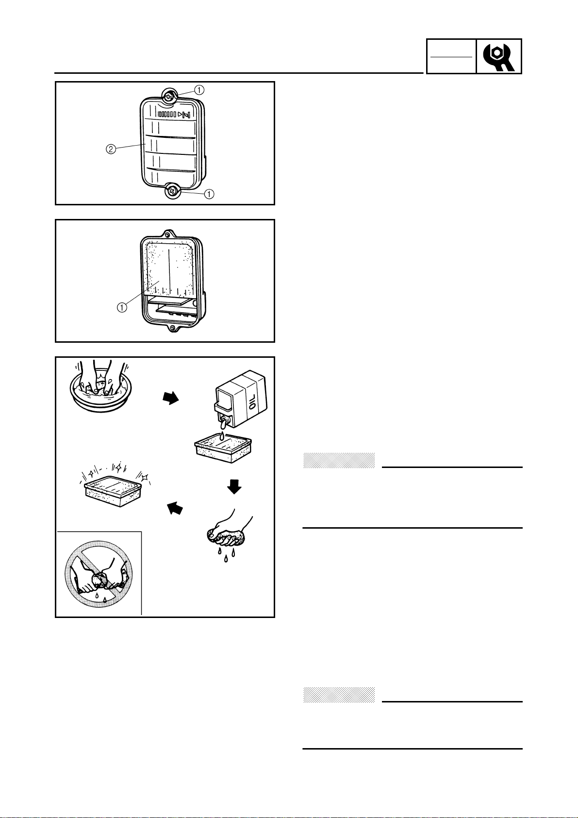
PILOT LIGHT
1. Check:
• Pilot light 1
Checking steps:
• Start the engine.
OVER
AC
LOAD
SVU2300H
2-13
• Make sure that the pilot light 1 turns on.
INSP
ADJ
TO RESET AC
RESTART ENGINE
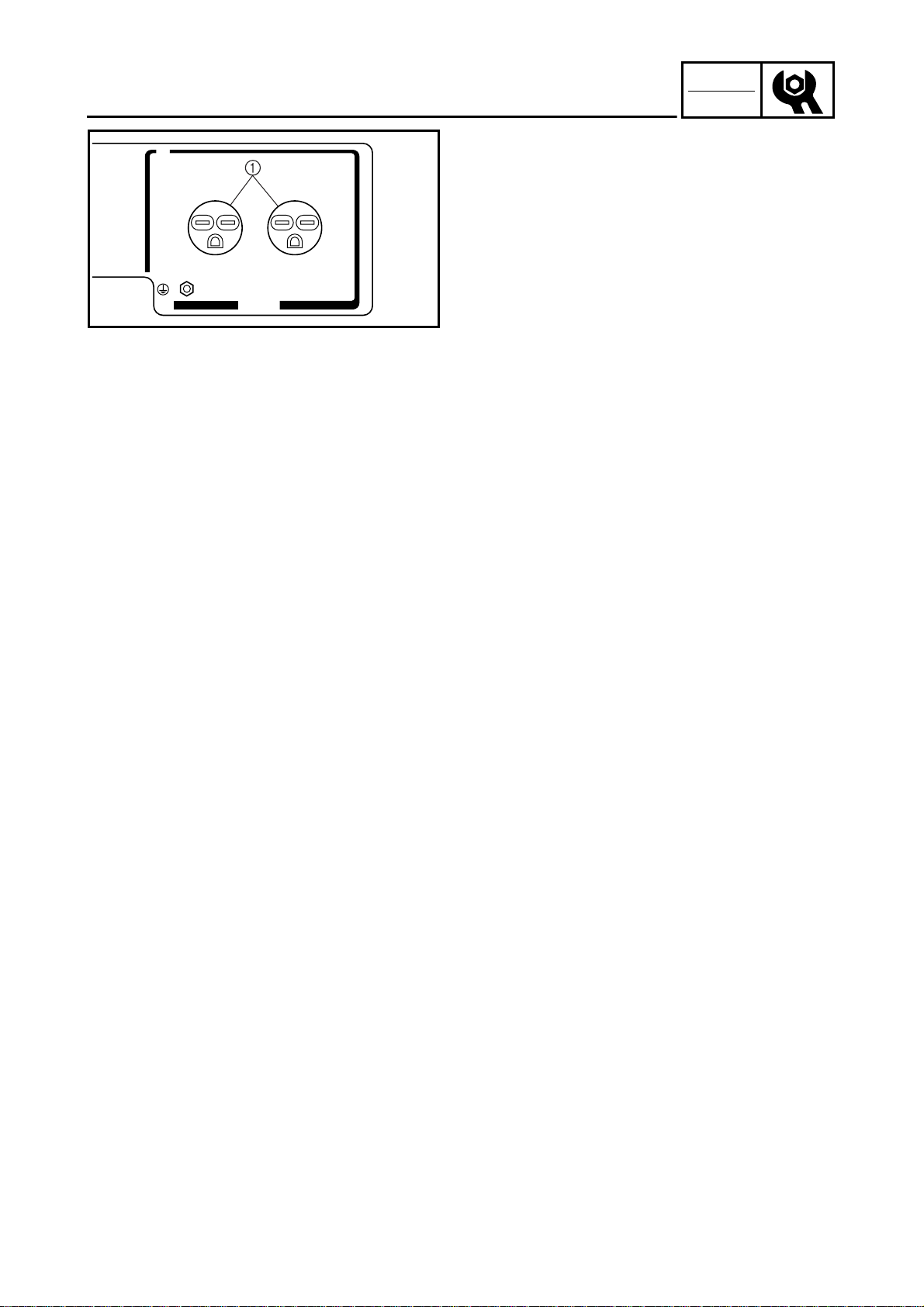
RECEPTACLE
RECEPTACLE
1. Check:
• AC receptacles (15 A) 1
Cracks/damage → Replace.
Poor connection → Correct.
AC~
SVU2310H
2-14
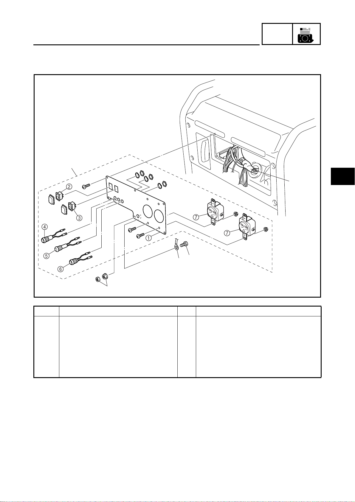
CONTROL PANEL
1
CONTROL PANEL
ENGINE
ENG
2
3
2
3
Order Job name/Part name Q’ty Remarks
Control panel assembly removal
1 Control panel assembly 1
2 Wire harness 1 Disconnect all couplers and lead wires.
3 Ground terminal 1
Remove the parts in the order listed
below.
For installation, reverse the removal procedure.
3
SVU3010H
3-1
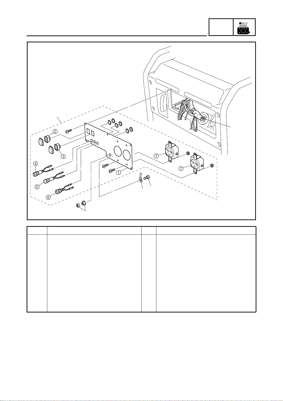
CONTROL PANEL
1
ENG
2
3
2
3
Order Job name/Part name Q’ty Remarks
1
2
3
4
5
6
7
Control panel disassembly
Control panel 1
Engine switch 1
Economy switch 1
Oil warning light 1
Pilot light 1
Over load warning light 1
AC receptacle (15 A) 2
Remove the parts in the order listed
below.
For assembly, reverse the disassembly
procedure.
SVU3010H
3-2
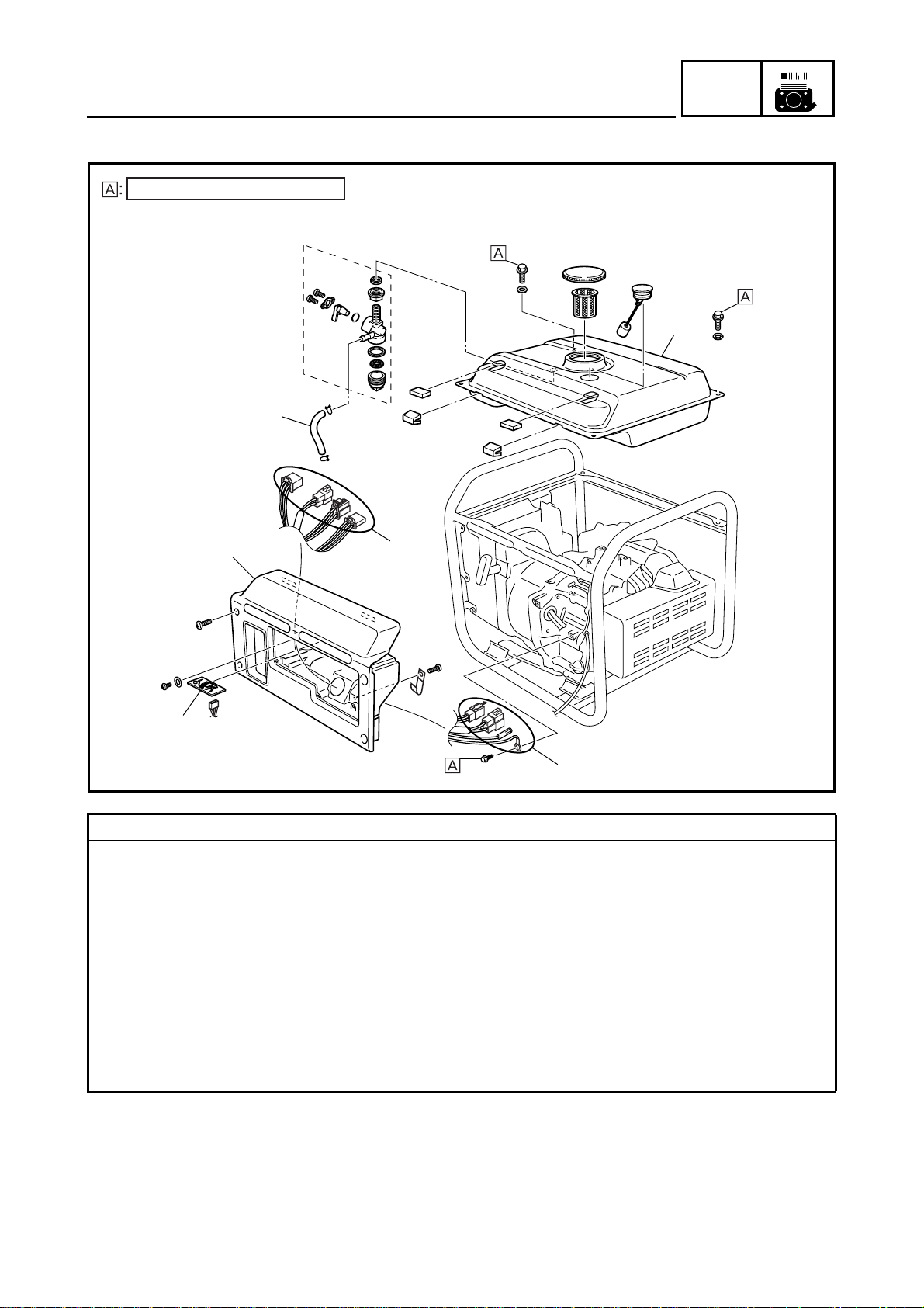
CONTROL BOX COVER AND FUEL TANK
CONTROL BOX COVER AND FUEL TANK
7 Nm (0.7 m · kg, 5.1 ft · lb)
4
ENG
5
1
2
Order Job name/Part name Q’ty Remarks
Control box cover and fuel tank
removal
Control panel assembly
1 Control box cover 1
2 Oil warning unit 1
3 Wire harness 1 Disconnect all couplers, lead wires and
4 Fuel hose 1 Set the fuel cock “OFF” position.
5 Fuel tank 1
3
3
Remove the parts in the order listed
below.
connections.
For installation, reverse the removal
procedure.
SVU3020H
3-3
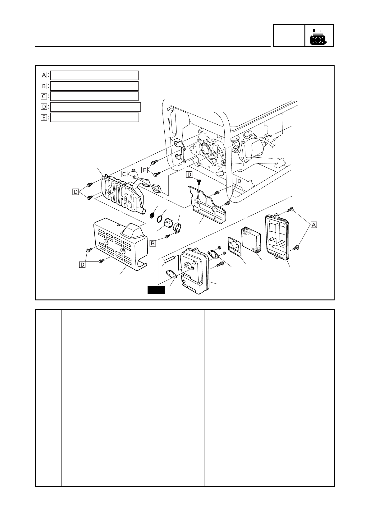
MUFFLER AND AIR CLEANER
MUFFLER AND AIR CLEANER
2 Nm (0.2 m · kg, 1.4 ft · lb)
4 Nm (0.4 m · kg, 2.9 ft · lb)
7 Nm (0.7 m · kg, 5.1 ft · lb)
10 Nm (1.0 m · kg, 7.2 ft · lb)
16 Nm (1.6 m · kg, 11 ft · lb)
2
ENG
7
6
4
5
3
9
13
11
10
1
12
14
New
Order Job name/Part name Q’ty Remarks
Muffler and air cleaner removal
Remove the parts in the order listed
below.
1 Muffler protector 1 1
2 Muffler 1
3 Muffler protector 2 1
4 Muffler band 1
5 Muffler cap 1
6 Washer 1
7 Muffler screen 1
8 Air filter case cover 1
9 Air filter element 1
10 Metal gasket 1
11 Plate 1
12 Air filter case 1
13 Breather hose 1
14 Gasket 1
For installation, reverse the removal
procedure.
8
SVU3030H
3-4

MUFFLER AND AIR CLEANER
BREATHER HOSE INSTALLATION
1. Install:
• Breather hose 1
• Air filter case 2
NOTE:
Contact the end of the breather hose 1 to the
stopper a of the air filter case 2.
SVU3040H
MUFFLER ASSEMBLY
1. Install:
• Muffler cap 1
• Muffler band 2
NOTE:
• Align the rim of the muffler cap 1 with the
protrusion a of the tail pipe.
• Contact the protrusion a against the rim of
SVU3050H
the muffler cap 1, without allowing it to
enter the slit.
ENG
SVU3060H
Muffler band:
4 Nm (0.4 m · kg, 2.9 ft · lb)
T
.
R
.
2. Install:
• Muffler nuts 1 and 2
• Muffler bolts 3 and 4
NOTE:
Tighten the nuts and bolts to the specified
torques in order from 1 to 4.
Muffler nut:
7 Nm (0.7 m · kg, 5.1 ft · lb)
T
.
R
.
Muffler bolt:
10 Nm (1.0 m · kg, 7.2 ft · lb)
3-5

CONTROL UNIT AND AC-CDI UNIT
CONTROL UNIT AND AC-CDI UNIT
2 Nm (0.2 m · kg, 1.4 ft · lb)
10 Nm (1.0 m · kg, 7.2 ft · lb)
3
1
ENG
2
Order Job name/Part name Q’ty Remarks
Control unit and AC-CDI unit
removal
Air cleaner assembly Refer to “MUFFLER AND AIR
Throttle control motor coupler Refer to “CARBURETOR”.
1 Control unit cover 1
2 Control unit 1
3AC-CDI unit 1
Remove the parts in the order listed
below.
CLEANER”.
For installation, reverse the removal
procedure.
SVU3070H
3-6

ENGINE
ENGINE
ENG
7 Nm (0.7 m · kg, 5.1 ft · lb)
16 Nm (1.6 m · kg, 11 ft · lb)
2
1
Order Job name/Part name Q’ty Remarks
Engine removal
Engine oil Refer to “OIL REPLACEMENT” in CHAP-
Control box cover and fuel tank assem-
bly
Muffler assembly and air cleaner
assembly
Control unit and AC-CDI unit Refer to “CONTROL UNIT AND AC-CDI
Carburetor assembly Refer to “CARBURETOR”.
1 Engine bracket 1
2 Engine assembly 1
Remove the parts in the order listed
below.
TER 2.
Refer to “CONTROL BOX COVER AND
FUEL TANK”.
Refer to “MUFFLER AND AIR
CLEANER”.
UNIT”.
For installation, reverse the removal
procedure.
SVU3080H
3-7

CYLINDER HEAD COVER AND CYLINDER HEAD
CYLINDER HEAD COVER AND CYLINDER HEAD
ENG
Order Job name/Part name Q’ty Remarks
Cylinder head cover and cylinder
head removal
Control box cover and fuel tank assem-
bly
Muffler assembly and air cleaner
assembly
Control unit cover and control unit Refer to “CONTROL UNIT AND AC-CDI
Carburetor assembly Refer to “CARBURETOR”.
Recoil starter, fan case cover, and fan
case
1 Spark plug cap 1
2 Spark plug 1
Remove the parts in the order listed
below.
Refer to “CONTROL BOX COVER AND
FUEL TANK”.
Refer to “MUFFLER AND AIR
CLEANER”.
UNIT”.
Refer to “RECOIL STARTER”.
SVU3090H
3-8

CYLINDER HEAD COVER AND CYLINDER HEAD
ENG
Order Job name/Part name Q’ty Remarks
3 Breather hose 1
4 Cylinder head cover 1
5Gasket 1
6 Air shroud 1
7 Cylinder head assembly 1
8 Cylinder head gasket 1
9 Dowel pin 2
10 Push rod 2
For installation, reverse the removal
procedure.
SVU3090H
3-9

CYLINDER HEAD COVER AND CYLINDER HEAD
PUSH ROD INSPECTION
1. Measure:
• Push rod runout
Runout limit:
0.5 mm (0.02 in)
Out of specification → Replace.
SVU3100H
CYLINDER HEAD INSPECTION
1. Inspect:
• Cylinder head combustion chamber
Check the combustion chamber for carbon deposits
Carbon deposits → Remove.
NOTE:
Be sure not to damage the contact surface of
SVU3110H
the cylinder.
ENG
SVU3120H
2. Inspect:
• Cylinder head
Cracks/damage around the hole of
spark plug → Replace.
3. Measure:
• Cylinder head warpage
Measure the warpage on the contact
surface of the cylinder head at six
points using the straight edge and thickness gauge.
Warpage limit:
0.05 mm (0.002 in)
Out of specification → Resurface or
replace.
3-10

CYLINDER HEAD COVER AND CYLINDER HEAD
CYLINDER HEAD ASSEMBLY
1. Install:
• Cylinder head bolts 1 to 4.
NOTE:
Tighten the bolts to the specified torque in two
steps and in order from 1 to 4.
ENG
SVU3130H
Cylinder head bolts:
20 Nm (2.0 m · kg, 14 ft · lb)
T
.
R
.
BREATHER HOSE ASSEMBLY
1. Inspect:
• Breather hose 1
NOTE:
Contact the end of the breather hose to the
reed valve stopper a.
SVU3140H
3-11

VALVE
VALVE
ENG
Order Job name/Part name Q’ty Remarks
Valve removal
Cylinder head assembly Refer to “CYLINDER HEAD COVER AND
1 Lock nut 2
2Adjuster 2
3 Rocker arm 2
4 Valve cotter 2
5 Valve spring retainer 2
6 Valve spring 2
7 Valve (intake) 1
8 Valve (exhaust) 1
9 Valve stem seal 1
Remove the parts in the order listed
below.
CYLINDER HEAD”.
For installation, reverse the removal
procedure.
SVU3150H
3-12

SVU3160H
VALVE
ENG
VALVE AND VALVE SPRING REMOVAL
1. Remove:
• Valve cotter 1
• Valve spring retainer 2
•Valve spring 3
•Valve 4
Remove the parts using the valve
spring compressor 5.
NOTE:
Do not compress the spring more than necessary.
Valve spring compressor:
90890-01253
SVU3180H
SVU3170H
VALVE AND VALVE SPRING INSPECTION
1. Measure:
• Valve stem length a
• Valve face diameter b
Valve stem length:
Intake: 65.9 mm (2.59 in)
Exhaust: 66.2 mm (2.61 in)
Valve face diameter:
Intake: 24.0 mm (0.94 in)
Exhaust: 22.0 mm (0.87 in)
Out of specification → Replace.
2. Measure:
• Valve stem diameter
a
Valve stem diameter:
Intake and exhaust:
5.5 mm (0.22 in)
Wear limit:
Intake: 5.4 mm (0.21 in)
Exhaust: 5.4 mm (0.21 in)
3-13
Out of specification → Replace.

SVU3190H
SVU3200H
VALVE
ENG
3. Measure:
• Valve stem runout
Runout limit:
0.01 mm (0.0004 in)
Out of specification → Replace.
NOTE:
The value is half of that indicated on the dial
gauge.
4. Measure:
• Valve spring free length a
Valve spring free length:
Intake and exhaust:
26.5 mm (1.04 in)
Limit: 25.0 mm (0.98 in)
Out of specification → Replace.
SVU3210H
SVU3220H
5. Measure:
• Valve spring tilt a
Tilt limit:
1.6 mm (0.06 in)
Out of specification → Replace.
6. Inspect:
• Valve spring contact surface
More than 2/3 of the contact surface
does not contact → Replace.
ROCKER ARM INSPECTION
1. Inspect:
•Rocker arm
Wear/damage/cracks → Replace.
SVU3230H
3-14

SVU3240H
VALVE
ENG
VALVE SEAT INSPECTION
1. Remove carbon deposits from the valve
face and valve seat.
2. Apply a small amount of coarse
mechanic's blueing dye (Dykem) to the
valve face.
3. Insert the vale into the valve guide and
use a valve lapper to contact the valve
face with the valve seat.
NOTE:
Do not rotate the valve while the valve face is
contacting the valve seat.
4. Measure:
• Valve face contact width
a
Make sure that the contact width along
the entire valve face is within specifications.
Valve face contact width (intake
and exhaust):
0.7 mm (0.03 in)
Limit: 1.7 mm (0.067 in)
SVU3250H
Out of specification/rough/eccentric
wear → Replace.
5. Measure:
• Valve seat contact width
a
Make sure that the contact width along
the entire valve seat is within specifications.
Valve seat contact width (intake
and exhaust):
0.7 mm (0.03 in)
Limit: 1.7 mm (0.067 in)
Out of specification/rough/eccentric
wear → Replace.
3-15

SVU3260H
VALVE
ENG
6. Remove the carbon deposits on the valve
face a and valve seat.
• Valve face contact seat width b
• Valve margin thickness c
Apply a small amount of coarse
mechanic’s blueing dye (Dykem) to the
valve seat.
Press the valve through the valve guide
and onto the valve seat to make a clear
impression.
• Valve margin thickness
Out of specification → Replace.
• Valve face contact width
Out of specification → Replace.
Valve seat width:
0.7 mm (0.03 in)
Valve margin thickness:
0.3 mm (0.012 in)
SVU3270H
VALVE LAPPING
1. Apply a coarse lapping compound evenly
on the valve face. Lap the valve by tapping and rotating the valve lapper
1
clockwise and counterclockwise.
2. Clean off all of the lapping compound
from the valve face and valve seat. Apply
fine lapping compound on the valve face
and lap the valve as in step 1.
3. If the contact width on the valve face
shines white along the entire face, apply
mechanic’s blueing dye (Dykem) to make
sure that there are traces of even contact
in the center of the valve face.
CAUTION:
Do not let the lapping compound enter the
gap between the valve stem and the valve
guide.
NOTE:
After every lapping procedure, clean off the
compound from the valve face and valve seat.
3-16

SVU3280H
VALVE
VALVE AND VALVE SPRING ASSEMBLY
1. Install:
•Valve 1
•Valve spring
• Valve spring retainer
• Valve cotter
Apply a small amount of molybdenum
disulfide oil to the valve stem and use
the valve spring compressor 5 to
install the parts.
Valve spring compressor:
90890-01253
2
4
ENG
3
New
CAUTION:
Do not compress the valve spring more
than necessary.
3-17

RECOIL STARTER
7 Nm (0.7 m · kg, 5.1 ft · lb)
RECOIL STARTER
4
ENG
3
2
1
Order Job name/Part name Q’ty Remarks
Recoil starter removal
Control box cover and fuel tank Refer to “CONTROL BOX COVER AND
Air cleaner assembly Refer to “MUFFLER AND AIR
Control unit cover, control unit Refer to “CONTROL UNIT AND AC-CDI
Engine mount nut (M6) Refer to “ENGINE”.
Carburetor assembly Refer to “CARBURETOR”.
1 Recoil starter assembly 1
2 Fan case cover 1
3 Fan case 1
4 Starter pulley 1
Remove the parts in the order listed
below.
FUEL TANK”.
CLEANER”.
UNIT”.
For installation, reverse the removal
procedure.
SVU3290H
3-18

5 Nm (0.5 m · kg, 3.6 ft · lb)
RECOIL STARTER
R
B
ENG
Order Job name/Part name Q’ty Remarks
Recoil starter disassembly
Remove the parts in the order listed
below.
1
2
3
4
5
6
7
8
9
Starter handle 1
Bolt 1
Drive plate 1
Clip 1
Drive pawl 2
Spring 2
Sheave drum 1
Starter spring 1
Starter case 1
For assembly, reverse the disassembly
procedure.
SVU3300H
3-19

SVU3310H
SVU3320H
RECOIL STARTER
ENG
RECOIL STARTER DISASSEMBLY
1. Remove:
• Starter handle 1
NOTE:
Make a knot a at the end of the starter rope to
prevent the rope from being retracted into the
starter case. Then, undo the knot b at the
starter handle to remove starter handle 1.
2. Remove:
• Sheave drum 1
CAUTION:
Be sure to press down on the drum sheave,
because the spring will spring out suddenly when it is removed from the sheave
drum.
SVU3330H
SVU3340H
3. Remove:
• Starter spring 1
RECOIL STARTER INSPECTION
1. Inspect:
• Starter rope 1
2. Inspect:
• Starter spring 2
Damage/deterioration → Replace.
3. Inspect:
•Drive pawl 1
• Drive plate 2
Wear/damage → Replace.
SVU3350H
3-20

SVU3360H
SVU3370H
RECOIL STARTER
ENG
RECOIL STARTER ASSEMBLY
1. Install:
• Starter spring 1
• Sheave drum 2
NOTE:
Engage starter spring outer hook a with
groove b marked “R” on the sheave drum 2.
Carefully wind the spring counterclockwise
and place it on the sheave drum 2.
2. Install:
• Sheave drum 1
• Starter rope 2
• Starter case 3
NOTE:
• Wind the starter rope 2 clockwise two turns
on the sheave drum 1.
• Engage starter spring inner hook a with the
strut b of the starter case 3 and install the
parts.
SVU3380H
SVU3390H
3. Install:
• Spring 1
•Drive pawl 2
NOTE:
Install the spring 1 and drive pawl 2 to the
“R” mark a.
4. Install:
•Clip 1
• Drive plate 2
NOTE:
Align the groove a of the drive plate 2 with
the sheave drum strut b, and then install the
parts.
3-21

RECOIL STARTER
ENG
SVU3400H
SVU3410H
5. Install:
•Bolt 1
After tightening the bolt, place starter
rope 2 in the cutout a in the sheave
drum, and wind it counterclockwise four
turns.
NOTE:
Make a knot b at the end of the starter rope to
prevent the rope from being retracted into the
recoil starter case.
3-22

GENERATOR
4 Nm (0.4 m · kg, 2.9 ft · lb)
7 Nm (0.7 m · kg, 5.1 ft · lb)
10 Nm (1.0 m · kg, 7.2 ft · lb)
65 Nm (6.5 m · kg, 47 ft · lb)
GENERATOR
ENG
4
5
3
12
11
12
7
10
6
8
7
2
1
Order Job name/Part name Q’ty Remarks
9
Generator removal
Remove the parts in the order listed
below.
Engine assembly Refer to “ENGINE”.
Spark plug cap Refer to “CYLINDER HEAD COVER AND
CYLINDER”.
Recoil starter, fan case cover, fan case Refer to “RECOIL STARTER”.
1 Spacer 1
2Fan 1
3 Ignition coil 1
4 Ground lead wire 1
5 Pulser coil 1
SVU3420H
3-23

4 Nm (0.4 m · kg, 2.9 ft · lb)
7 Nm (0.7 m · kg, 5.1 ft · lb)
10 Nm (1.0 m · kg, 7.2 ft · lb)
65 Nm (6.5 m · kg, 47 ft · lb)
GENERATOR
ENG
4
5
3
12
11
12
7
10
6
8
7
2
9
1
SVU3420H
Order Job name/Part name Q’ty Remarks
6 Magneto rotor 1 Remove the magneto rotor and stator coil
assembly as a set.
7 Tube 2
8 Stator coil assembly 1
9 Woodruff key 1
10 Clamp 1
11 Grommet 1
12 Dowel pin 2
For installation, reverse the removal
procedure.
3-24

SVU3430H
GENERATOR
ENG
MAGNETO ROTOR AND STATOR COIL
ASSEMBLY REMOVAL
CAUTION:
The magnetic force of the magneto rotor is
very strong. Therefore, be sure to remove
the magneto rotor and stator coil assembly
together as a set, otherwise they may be
damaged.
1. Remove:
• Magneto rotor nut 1
NOTE:
Attach the sheave holder 2 to hold the magneto rotor.
Sheave holder:
90890-01701
SVU3440H
SVU3450H
2. Remove:
• Stator coil assembly bolts 1
NOTE:
Turn the magneto rotor until the stator coil
assembly bolts are visible through the holes in
the rotor, and then remove the bolts.
3. Remove:
• Stator coil assembly bolts 2
• Tubes
NOTE:
• Turn the magneto rotor until the stator coil
assembly bolts are visible through the holes
in the rotor, and then remove the bolts.
• Align the keyway a of the magneto rotor
with the stator coil assembly bolts 2 so that
they are in a straight line. The piston is at
top dead center when keyway and bolts are
in this position.
3-25

SVU3460H
GENERATOR
ENG
4. Remove:
• Magneto rotor 1
NOTE:
• Remove the magneto rotor 1 together with
the stator coil assembly using the rotor
puller 2.
• Fully tighten the tool holding bolts, making
sure the tool body is parallel with the magneto rotor. If necessary, one screw may be
backed out slightly to level the tool body.
CAUTION:
The magnetic force of the magneto rotor is
very strong. Therefore, do not change the
position of the magneto rotor and stator
coil assembly during or after removal, otherwise they may be damaged.
SVU3470H
Rotor puller:
90890-01362
MAGNETO ROTOR AND STATOR COIL
ASSEMBLY INSTALLATION
1. Install:
• Woodruff key 1
CAUTION:
Be sure to remove any oil or grease from
the tapered portion of the magneto rotor
using a cloth dampened with thinner.
2. Install:
• Magneto rotor
• Stator coil assembly
• Washer
• Magneto rotor nut
3-26

GENERATOR
ENG
CAUTION:
Be sure to remove any oil or grease from
the tapered portion of the magneto rotor
using a cloth dampened with thinner.
NOTE:
When installing the magneto rotor, make sure
the woodruff key is properly seated in the key
way of the crankshaft.
3. Install:
• Stator coil assembly bolts 1
• Tubes
Stator coil assembly bolts:
10 Nm (1.0 m · kg, 7.2 ft · lb)
T
.
R
.
SVU3490H
SVU3480H
NOTE:
• Turn the magneto rotor until the stator coil
assembly bolts are visible though the holes
in the rotor, and then remove the bolts 1.
• Align the keyway a of the magneto rotor
with the stator coil assembly bolts 1 so that
they are in a straight line. The piston is at
top dead center when keyway and bolts are
in this position.
4. Tighten:
• Magneto rotor nut 1
• Washer
Magneto rotor nut:
65 Nm (6.5 m · kg, 47 ft · lb)
T
.
R
.
NOTE:
Tighten the magneto rotor nut 1 using the
sheave holder 2.
3-27
Sheave holder:
90890-01701

CRANKCASE COVER AND CAMSHAFT
CRANKCASE COVER AND CAMSHAFT
ENG
Order Job name/Part name Q’ty Remarks
Crankcase cover and camshaft
removal
Engine assembly Refer to “ENGINE”.
Cylinder head assembly Refer to “CYLINDER HEAD COVER AND
Recoil starter, fan case cover, fan
case, fan, magneto rotor, and stator
coil
1 Crankcase cover 1
2Gasket 1
3 Dowel pin 2
4Bracket 1
5 Oil level switch 1
6 Camshaft 1
7 Valve lifter 2
8Bracket 1
Remove the parts in the order listed
below.
CYLINDER HEAD”.
Refer to “RECOIL STARTER” and “GEN-
ERATOR”.
For installation, reverse the removal
procedure.
SVU3500H
3-28

CRANKCASE COVER AND CAMSHAFT
CAMSHAFT INSPECTION
1. Inspect:
•Camshaft
Damage → Replace.
SVU3510H
2. Measure:
• Cam lobes length a and b
Out of specifications → Replace.
Cam lobes length:
Intake : 26.9 ± 0.05 mm
Wear limit: 26.75 mm (1.053 in)
SVU3520H
Wear limit: 21.85 mm (0.860 in)
Exhaust : 26.68 ± 0.05 mm
Wear limit: 26.53 mm (1.044 in)
Wear limit: 21.88 mm (0.861 in)
ENG
(1.06 ± 0.002 in)
: 22.0 ± 0.05 mm
(0.87 ± 0.002 in)
(1.05 ± 0.002 in)
: 22.03 ± 0.05 mm
(0.87 ± 0.002 in)
SVU3530H
SVU3540H
3. Inspect:
• Surface of camshaft gear teeth
• Decompressor
Wear/damage → Replace.
4. Measure:
• Camshaft diameter a
Out of specification → Replace.
Camshaft diameter:
14.965 ~ 14.990 mm
(0.5892 ~ 0.5902 in)
Wear limit: 14.950 mm (0.59 in)
3-29

CRANKCASE COVER AND CAMSHAFT
VALVE LIFTER INSPECTION
1. Inspect:
• Valve lifter
Damage → Replace.
SVU3550H
CAMSHAFT ASSEMBLY
1. Install:
• Camshaft 1
CAUTION:
Be sure to align the hole a of camshaft
gear with the crankshaft gear mark b.
SVU3560H
ENG
SVU3570H
SVU3580H
CRANKCASE COVER INSPECTION
1. Inspect:
• Crankcase cover
1
Damage → Replace.
• Bearing 2
Noise/wear/rotational failure →
Replace.
CRANKCASE COVER INSTALLATION
1. Install:
• Crankcase cover bolts 1 to 6
NOTE:
Tighten the bolts to the specified torque in two
steps and in order from 1 to 6.
Crankcase cover bolts:
22 Nm (2.2 m · kg, 16 ft · lb)
T
.
R
.
3-30

PISTON, CONNECTING ROD, CRANKSHAFT AND
CRANKCASE
PISTON, CONNECTING ROD, CRANKSHAFT AND CRANKCASE
ENG
Order Job name/Part name Q’ty Remarks
Piston, connecting rod, crankshaft
and crankcase removal
Engine assembly Refer to “ENGINE”.
Cylinder head assembly Refer to “CYLINDER HEAD COVER AND
Recoil starter, fan case cover, and fan
case
Fan, magneto rotor, and stator coil
assembly
Crankcase cover and camshaft Refer to “CRANKCASE COVER AND
1 Connecting rod cap 1
2 Crankshaft 1
3 Connecting rod 1
4 Piston pin circlip 2
5 Piston pin 1
6Piston 1
7 Piston ring 3
Remove the parts in the order listed
below.
CYLINDER HEAD”.
Refer to “RECOIL STARTER”.
Refer to “GENERATOR”.
CAMSHAFT”.
For installation, reverse the removal
procedure.
SVU3590H
3-31

PISTON, CONNECTING ROD, CRANKSHAFT AND
CRANKCASE
CRANKCASE (CYLINDER) INSPECTION
1. Measure:
• Cylinder inside diameter
NOTE:
Take side to side a and front to back b measurements at each of the three locations A, B,
C (total of six measurements), and then find
the average of the measurements.
Maximum wear = Maximum A, B, C.
Cylinder taper = Maximum A – Minimum C.
Out of specification → Replace.
Cylinder inside diameter:
66.00 ~ 66.02 mm
(2.5984 ~ 2.5990 in)
Cylinder inside diameter wear
limit:
66.020 mm (2.5990 in)
Cylinder taper limit:
SVU3600H
0.05 mm (0.002 in)
ENG
SVU3610H
2. Measure:
• Cylinder warpage
NOTE:
Measure the warpage on the contact surface
of the cylinder head at six points using a
straight edge and thickness gauge.
Out of specification → Resurface or
replace.
Warpage limit:
0.05 mm (0.002 in)
PISTON AND PISTON PIN INSPECTION
1. Measure:
• Piston skirt diameter P
= 10 mm (0.4 in) from the piston bottom edge
a
Out of specification → Replace.
SVU3620H
Piston skirt diameter:
66.0 mm (2.598 in)
Wear limit:
65.9 mm (2.594 in)
3-32

PISTON, CONNECTING ROD, CRANKSHAFT AND
CRANKCASE
2. Measure:
• Piston clearance
Out of specification → Rebore or
replace cylinder and replace piston and
piston rings.
Piston clearance:
0.015 ~ 0.040 mm
(0.00059 ~ 0.00157 in)
Piston clearance =
Cylinder inside diameter –
Piston skirt diameter
ENG
SVU3630H
SVU3640H
SVU3650H
3. Measure:
• Piston pin hole inside diameter
Out of specification → Replace.
Piston pin hole inside diameter:
16.002 ~ 16.013 mm
(0.6300 ~ 0.6304 in)
Wear limit:
16.020 mm (0.6307 in)
4. Measure:
• Piston pin diameter
Out of specification → Replace.
Piston pin diameter:
15.995 ~ 16.000 mm
(0.6297 ~ 0.6299 in)
Wear limit:
15.950 mm (0.6280 in)
5. Inspect:
• Check that the piston pin enters
smoothly into the piston pin hole.
If the piston pin fits tightly into the piston, check the piston pin hole. If there is
any protrusion, use a knife or scraper to
gently remove it so that the piston pin
can be pushed in gently with your fingers.
3-33

PISTON, CONNECTING ROD, CRANKSHAFT AND
CRANKCASE
PISTON RING INSPECTION
1. Measure:
• Piston ring end gap
Out of specification → Replace.
NOTE:
Insert the piston ring 1 into the cylinder, and
push it approximately 5 mm (0.2 in) into the cylinder. Push in the ring with the piston crown so that
SVU3660H
the ring is at right angles to the cylinder bore.
Ring end gap Wear limit
ENG
SVU3670H
Top
ring
2nd
ring
Oil
ring
0.2 ~ 0.4 mm
(0.008 ~ 0.016 in)
0.2 ~ 0.4 mm
(0.008 ~ 0.016 in)
0.2 ~ 0.4 mm
(0.008 ~ 0.016 in)
0.9 mm
(0.0354 in)
0.9 mm
(0.0354 in)
0.9 mm
(0.0354 in)
2. Measure:
• Piston ring side clearance
Out of specification → Replace.
Use a thickness gauge 1.
Top
ring
2nd
ring
Piston ring side
clearance
0.04 ~ 0.08 mm
(0.0016 ~ 0.0031 in)
0.02 ~ 0.06 mm
(0.0008 ~ 0.0024 in)
Wear limit
0.1 mm
(0.0039 in)
NOTE:
• Clean carbon deposits from the piston ring
grooves and rings before measuring the
side clearance.
• Measure the side clearance at several portions.
SVU3680H
CRANKSHAFT INSPECTION
1. Measure:
• Crankshaft runout limit
Use a dial gauge.
Out of specification → Replace.
Runout limit:
0.04 mm (0.0016 in)
3-34

PISTON, CONNECTING ROD, CRANKSHAFT AND
CRANKCASE
2. Inspect:
• Crankshaft gear 1
Wear/damage → Replace.
SVU3690H
3. Measure:
• Crank pin outside diameter a
Wear/damage → Replace.
Use a micrometer.
Out of specification → Replace.
Crank pin outside diameter:
28.0 mm (1.102 in)
Wear limit:
SVU3700H
27.9 mm (1.098 in)
ENG
SVU3710H
CONNECTING ROD OIL CLEARANCE
INSPECTION
NOTE:
Measure the oil clearance if replacing the
crankshaft or connecting rod.
1. Place a piece of Plastigauge 1 on the
crank pin horizontally.
NOTE:
Clean off oil from all parts thoroughly.
2. Install:
• Connecting rod 1
• Connecting rod cap 2
SVU3720H
NOTE:
Tighten the cap bolts so that the crankshaft
does not move while the oil clearance is being
measured.
Connecting rod cap bolt:
12 Nm (1.2 m · kg, 8.7 ft · lb)
T
.
R
.
3-35

PISTON, CONNECTING ROD, CRANKSHAFT AND
CRANKCASE
3. Remove:
• Connecting rod cap
• Connecting rod
4. Measure:
• Widest portion of the pressed Plasti-
gauge
Out of specification → Replace crankshaft or connecting rod, and then mea-
SVU3730H
sure the clearance again.
Connecting rod big end oil clearance:
0.015 ~ 0.040 mm
(0.0006 ~ 0.0016 in)
Wear limit:
0.1 mm (0.004 in)
ENG
SVU3740H
PISTON RING AND PISTON ASSEMBLY
1. Install:
•Top ring 1
•2nd ring 2
• Oil ring 3
NOTE:
• Be sure to install the second ring so that the
manufactures mark a faces towards the
piston head.
• Make sure that the piston rings move
smoothly.
2. Apply 4-stroke engine oil to the inside of
the connecting rod small end.
3. Install:
• Piston
• Piston pin
• Piston pin circlip
1
2
3
New
SVU3750H
NOTE:
• Make sure that the “YAMAHA” mark a on
the connecting rod faces toward the crankcase cover.
• Make sure that the “ ” mark b on the piston head faces toward the push rod.
3-36

PISTON, CONNECTING ROD, CRANKSHAFT AND
CRANKCASE
CRANKSHAFT ASSEMBLY
1. Make sure that the end gap of each piston
ring is positioned, as shown in the illustration.
ENG
SVU3780H
SVU3760H
SVU3770H
Top ring
2nd ring
Oil ring
a
b
c
2. Install:
• Piston ring compressor 1
Piston ring compressor:
90890-05158
3. Install:
• Connecting rod 1
• Piston 2
NOTE:
• Make sure that the “ ” mark a on the piston head faces toward the push rod.
• Make sure that the “YAMAHA” mark b on
the connecting rod faces toward the crankcase cover.
SVU3790H
4. Install:
• Crankshaft
• Connecting rod cap
NOTE:
Make sure that the “ ” mark a on the connecting rod is aligned with the “ ” mark b on
the rod cap.
Connecting rod cap bolt:
12 Nm (1.2 m · kg, 8.7 ft · lb)
T
.
R
.
5. Install:
•Camshaft
• Crankcase cover
Refer to “CRANKCASE COVER AND
CAMSHAFT”.
3-37

CARBURETOR
CARBURETOR
ENG
Order Job name/Part name Q’ty Remarks
Carburetor removal
Air cleaner assembly Refer to “MUFFLER AND AIR
1 Choke knob 1
2 Choke cable 1
3 Fuel hose 1
4 Throttle control motor cover 1
5 Throttle control motor coupler 1
6 Carburetor assembly 1
7Gasket 1
8 Carburetor joint 1
9Gasket 1
Remove the parts in the order listed
below.
CLEANER”.
For installation, reverse the removal
procedure.
SVU3800H
3-38

CARBURETOR
ENG
Order Job name/Part name Q’ty Remarks
Carburetor disassembly
1
Throttle control motor assembly 1
2
Throttle controller bracket 1
3
Bracket 1
4
Bolt 1
5
Gasket 1
6
Drain screw 1
7
Float chamber 1
8
Gasket 1
9
Float pin 1
0
Float 1
A
Needle valve 1
B
Main nozzle 1
C
Main jet 1
D
Pilot screw 1
E
Pilot jet 1
Remove the parts in the order listed
below.
For assembly, reverse the disassembly
procedure.
SVU3810H
3-39

SVU3820H
SVU3830H
CARBURETOR
ENG
FLOAT HEIGHT INSPECTION
1. Measure:
• Float height a
Out of specification → Replace.
NOTE:
Lift up the float height so that the tip of the float
valve lightly contacts the float arm, and then
measure the float height a. (This measurement should be made with the gasket
removed.)
Float height:
16.0 mm (0.63 in)
SVU3840H
SVU3850H
2. Clean:
• Carburetor body
Blow out all passages, jets, and carburetor body with compressed air.
3. Inspect:
• Valve seat
Wear/damage → Replace.
Dirt → Clean.
Wear at groove
1
Dirt
2
3-40

CARBURETOR
ENG
CHOKE CABLE INSTALLATION
1. Inspect:
• Choke knob 1
NOTE:
Push the choke knob 1 entirely in before
installing it to the frame.
2. Install
• Casing cap (choke cable) 2
NOTE:
Place the choke knob casing cap against the
stay 3.
3. Install:
• Inner cable 4
NOTE:
Place the carburetor choke valve in its fully
open position a, insert the tip of the inner
cable into drum hole 5, and then secure it in
place with the screw 6.
SVU3860H
SVU3870H
Screw:
1 Nm (0.1 m · kg, 0.7 ft · lb)
T
.
R
.
THROTTLE CONTROL MOTOR
1. Inspect:
• Throttle control motor 1
NOTE:
• Install the shaft a of the throttle control
motor by aligning it with the groove b of the
throttle shaft.
• Install the throttle valve, and then make sure
that it moves smoothly.
• When installing the control motor, fully open
the throttle valve, otherwise starting the
engine may be difficult.
3-41

TROUBLESHOOTING
ENGINE
ENGINE DOES NOT START
TROUBLESHOOTING
ENG
Check that the oil warning
light turns ON by pulling the
starter rope.
LIGHT ON
Check engine oil level.
SUFFICIENT
Check fuel level. INSUFFI-
SUFFICIENT Check if fuel is deteriorated.
Check fuel cock lever position.
“ON” “OFF” Set to “ON”.
Check if fuel travels to fuel
cock.
GOOD NOT GOOD
Remove spark plug, attach
it to spark plug cap, and
then ground the spark plug
to check for spark.
GOOD
SPARK
DOSE NOT
TURN ON
INSUFFI-
CIENT
CIENT
WEAK OR
NO SPARK
Check connections between oil warning
unit and oil level switch.
GOOD NOT GOOD
GOOD NOT GOOD
• Check spark plug for dirt and check
spark plug gap.
• Check for voltage leakage d ue to faulty
connection or broken insulation of the
high tension cord.
• Check AC-CDI unit connector for corrosion or faulty connection.
• Check the ignition system. Refer to
“IGNITION SYSTEM” in CHAPTER 4.
GOOD NO GOOD
Replace oil warning
light, oil warning
unit, or oil level
switch.
Add.
Add.
Replace.
Clean fuel tank and
fuel cock.
Clean.
Correct.
Replace.
*
Install a substitute AC-CDI unit to check
spark conditions.
GOOD SPARK
3-42
WEAK OR NO
SPARK
Replace original
AC-CDI unit.

TROUBLESHOOTING
ENG
*
Check carburetor for
clogged passages or fuel
overflow.
GOOD NO GOOD Clean.
Measure valve clearance.
OUT OF
GOOD
Check compression using
compression gauge.
OUT OF
SPECIFICA-
TION
Check valve face and valve
seat for wear.
GOOD WEAR
SPECIFICA-
TION
GOOD
Adjust.
Resurface or
replace.
Check if the timing marks
on the crankshaft and camshaft are aligned.
GOOD NO GOOD Correct or replace.
Check if there is seizure or
wear on the piston, piston
ring, or cylinder.
GOOD
Check the condition of the throttle control
system.
Refer to “THROTTLE CONTROL SYSTEM”.
SEIZURE
OR WEAR
Rebore or replace.
3-43

TROUBLESHOOTING
ENG
ENGINE STARTS BUT STALLS
Check fuel level.
SUFFICIENT
Check if fuel cock is
clogged.
GOOD NO GOOD Clean.
Check if fuel hose is
clogged.
GOOD NO GOOD Clean.
INSUFFI-
CIENT
Add.
• Check if carburetor
retaining nuts are loose.
• Check if there is air suction due to a damaged
carburetor joint or gasket.
GOOD NO GOOD
Measure valve clearance.
OUT OF
GOOD
Check compression using
a compression gauge.
GOOD
Check if there is proper
clearance between pulser
coil and magneto rotor.
GOOD
SPECIFICA-
TION
OUT OF
SPECIFICA-
TION
OUT OF
SPECIFICA-
TION
Improperly tightened cylinder head
• Tighten the carburetor bolts
securely.
• Replace carburetor joint or gasket
with a new one.
Adjust.
Tighten securely.
Adjust.
Check the condition of the throttle control
system.
Refer to “THROTTLE CONTROL SYSTEM”.
3-44

TROUBLESHOOTING
ENG
ENGINE SPEED DOES NOT INCREASE
Check if the electric equipment
consumes too much wattage for
this generator.
GOOD TOO MUCH Use a generator with a larger capacity.
Check air filter element for dirt.
GOOD NOT GOOD Clean.
Check spark plug for dirt and
check spark plug gap.
GOOD NOT GOOD Clean or adjust.
Check valve clearance.
GOOD
Check if main passages such as,
the main jet, in the carburetor are
clogged.
GOOD NO GOOD Disassemble or clean.
OUT OF SPECI-
FICATION
Adjust.
Check for air suction due to a
damaged throttle shaft seal, carburetor joint, or gasket.
GOOD NO GOOD Disassemble or replace.
Check compression using compression gauge.
GOOD
Check valve face and valve seat
for wear.
GOOD WEAR Resurface or replace.
Check if the timing marks on the
crankshaft and camshaft are
aligned.
GOOD NO GOOD Correct.
Check if there is seizure or wear
on piston, piston ring, or cylinder.
GOOD
TOO HIGH Decarbonize combustion chamber if there are
TOO LOW
SEIZURE OR
WEAR
carbon deposits.
Rebore or replace.
Check the condition of the throttle
control system.
Refer to “THROTTLE CONTROL
SYSTEM”.
3-45

TROUBLESHOOTING
ENGINE SPEED IS UNEVEN
Check fuel level.
SUFFICIENT INSUFFICIENT Add.
Check if fuel is deteriorated.
GOOD NO GOOD Replace.
Check if fuel cock is clogged.
GOOD NO GOOD Clean.
Check spark plug for dirt and
check spark plug gap.
GOOD NO GOOD Clean or adjust.
Measure valve clearance.
GOOD
OUT OF SPECI-
FICATION
Adjust.
ENG
While the engine is operating, pull
the choke knob approximately 1/3
to 1/2 way out, and then check th e
engine operating condition.
STABLE UNSTABLE Inspect from
Check if pilot screw of the carburetor is turned the proper number of
turns out and there is sullicient
fuel.
GOOD NO GOOD Adjust.
Check for air suction due to a
damaged throttle shaft seal, carburetor joint, or gasket.
GOOD NO GOOD Disassemble or replace.
Check if slow or main passages
such as, the pilot jet and main jet,
in carburetor are clogged.
GOOD NO GOOD Disassemble or clean.
*
**
.
3-46

TROUBLESHOOTING
*
**
Check valve face and valve seat
for wear.
GOOD WEAR Resurface or replace.
Check if there is seizure or wear
on piston, piston ring, or cylinder.
GOOD
Check the condition of the throttle
control system.
Refer to “THROTTLE CONTROL
SYSTEM”.
SEIZURE OR
WEAR
Rebore or replace.
ENG
3-47

TROUBLESHOOTING
ENG
THROTTLE CONTROL SYSTEM
ENGINE DOES NOT START, ENGINE STARTS BUT STALLS, ENGINE SPEED DOES NOT
INCREASE, OR ENGINE SPEED IS UNEVEN.
Check AC output.
GOOD NO GOOD Refer to “GENERATOR SYSTEM” in CHAPTER 4.
Rotate the shaft of the throttle control
motor to check if it turns smoothly with
slight resistance.
GOOD NO GOOD Replace the throttle control motor.
Measure the coil resistance between 3-1,
3-2, 3-4, and 3-5 of the throttle control
motor. (Tester range: Ω × 100)
250 Ω ± 7% /25 °C (77 °F)
54321
1
5
3
2
GOOD
Check the connections of the wire harness connectors and couplers, and the
wires for an open circuit or short circuit.
GOOD NO GOOD Correct or replace.
Replace the control unit.
OUT OF SPECIFI-
CATION
4
SVU3880H
Replace the throttle control motor.
3-48

TROUBLESHOOTING
ENG
With no load, engine speed does not increase when economy control switch is set to
“OFF”.
With no load, engine speed does not decrease when economy control switch is set to
“ON”.
With load, engine speed does not increase when economy control switch is set to “ON”.
Check AC output.
GOOD NO GOOD Refer to “GENERATOR SYSTEM” in CHAPTER 4.
Check condition of the throttle control motor.
GOOD NO GOOD Replace throttle control motor.
Check economy switch.
GOOD NO GOOD Replace economy switch.
Check the connections of the wire
harness connectors and couplers,
and the wires for an open circuit or
short circuit.
GOOD NO GOOD Correct or replace.
Replace the control unit.
3-49

ELECTRICAL COMPONENTS
Control unit
1
Engine switch
2
Economy switch
3
Oil warning unit
4
AC receptacle (15 A)
5
Ground terminal
6
Overload warning light (Red)
7
Pilot light (Green)
8
Oil warning light (Red)
9
Oil level switch
0
Spark plug
A
Throttle control motor
B
Pulser coil
C
Magneto rotor
D
Stator coil assembly
E
AC-CDI unit
F
Ignition coil
G
ELECTRICAL COMPONENTS
ELECTRICAL
ELEC
–+
SVU4010H
ECON.
SW
AC
OVER
LOAD
TO RESET AC
RESTART ENGINE
SVU4020H
AC~
4-1
SVU4030H

CIRCUIT DIAGRAM
Pulser coil
Throttle control motor
Coupler is Black.ÉCoupler is Red.
H
I
È
Economy switch
Overload warning lightAEngine switchBOil warning light
9
0
Oil warning unit
Oil level switch
Spark plugFIgnition coilGAC-CDI unit
C
D
E
–+
L
Y
B/W
ELEC
W ...........White
Y ............Yellow
COLOR CODE
B............Black
Br...........Brown
B/W........Black/White
G............Green
G/Y.........Green/Yellow
W/L ........White/Blue
L.............Blue
Or...........Orange
R............Red
4
CIRCUIT DIAGRAM
G/Y
R
Br
Br
Br
G/Y
B
R
R
R
Y
B/W
Y
B
R
Or
Or
B/W
R
R
Y
B/W
L
Y
R
Main coil
Sub coil (AC control)3Charge coil
1
2
(ignition source)4Generator assembly5Control unit6Pilot light
AC receptacle (15 A)8Ground terminal
7
OrOrOr
G/Y
Or
G/Y
G/Y
B
Or
B/W
Y
R
Or
Y
R
Or
B
Br
Gy
R
R
Or
Or
R
R
R
B/W
R G/Y
B/W
R G/Y
L
B/W
B/W
W/L
W/L
G/Y
G/Y
G/Y
G/Y
B/W
L
Y
R
G
Or
L
Y
R
G
Or
W/L
B
B
R
Br
R
R
R
WB
Y
YY
Y
YY
Y
YY
4-2
G/Y
B/W
SVU4040H

SVU4050H
–+
SWITCHES
ELEC
SWITCHES
CHECKING SWITCH CONTINUITY
Use a tester to check the terminals for continuity. If the continuity is faulty at any point,
replace the switch.
Pocket tester:
90890-03112
NOTE:
• Set the pocket tester to “0” before starting a
test.
• When testing the switch for continuity the
pocket tester should be set to the “× 1”
range.
• When checking the switch turn it on and off a
few times.
Ω
4-3

IGNITION SYSTEM
IGNITION SYSTEM
TROUBLESHOOTING CHART
NO SPARK OR WEAK SPARK
Inspection steps:
1. Spark plug
2. Ignition spark gap
3. Spark plug cap
4. Ignition coil resistance
5. Charge coil resistance
NOTE:
• Remove the following part(s) before troubleshooting.
1)Spark plug
• Use the following special tool(s) for troubleshooting.
6. Pulser coil resistance
7. Engine switch
8. Oil level switch
9. Wire harness
ELEC
–+
Pocket tester:
90890-03112
1. Spark plug
• Check the spark plug condition.
Refer to “SPARK PLUG” in CHAPTER 2.
GOOD
2. Ignition spark gap
• Disconnect the spark plug cap 1 from the
spark plug.
• Connect the ignition checker 2 as shown.
Spark plug cap 1 → Ignition checker
Ignition checker lead → Spark plug
3
Ignition checker:
90890-06754
NO GOOD
Repair or replace the spark plug.
4-4
SVU4060H

• Crank the engine and measure the ignition spark gap a.
IGNITION SYSTEM
ELEC
–+
Minimum spark gap:
6 mm (0.24 in)
OUT OF
SPECIFICATION
OR NO SPARK
3. Spark plug cap
• Remove the spark plug cap.
• Connect the pocket tester (Ω × 1k) to the
spark plug.
Tester (+) lead → Spark plug side 1
Tester (–) lead → Spark plug lead 2
MEETS SPECIFICATION
The ignition system is good.
NOTE:
• Do not pull out the plug cap from the spark
plug lead.
• Remove → Turn the plug cap counterclockwise.
•Install → Turn the plug cap clockwise.
• Inspect the spark plug lead for cracks or
deterioration, when install the pug cap.
• Cut 5 mm off the end of the spark plug lead,
and then connect it to the plug cap.
OUT OF SPECIFICATION
SVU4070H
Spark plug cap resistance:
4.0 ~ 6.0 kΩ at 20 °C (68 °F)
MEETS
SPECIFICATION
4. Ignition coil resistance
• Remove the ignition coil.
1)Primary coil resistance
• Connect the pocket tester (Ω × 1k) to the
primary terminal.
Tester (+) lead → White/Blue terminal 1
Tester (–) lead → Black terminal 2
Primary coil resistance:
0.11 Ω ± 15% at 20 °C (68 °F)
MEETS
SPECIFICATION
*
Replace the spark plug cap.
SVU4080H
OUT OF SPECIFICATION
Replace the ignition coil.
4-5

*
MEETS
SPECIFICATION
2)Secondary coil resistance
• Connect the pocket tester (Ω × 1) to the
secondary terminal.
Tester (+) lead → High-tension cord 1
Tester (–) lead → Black terminal 2
IGNITION SYSTEM
ELEC
–+
SVU4090H
Secondary coil resistance:
6.7 kΩ ± 20% at 20 °C (68 °F)
MEETS
SPECIFICATION
5. Charge coil resistance
• Remove the coupler of charge coil 1.
• Connect the pocket tester (Ω × 1) to the
secondary terminal.
Tester (+) lead → Red terminal 2
Tester (–) lead → Green/Yellow terminal 3
Charge coil resistance:
0.5 Ω ± 10% at 20 °C (68 °F)
MEETS
SPECIFICATION
OUT OF SPECIFICATION
Replace the ignition coil.
Or
Or
G/Y
R
G/Y
R
Or
Or
OUT OF SPECIFICATION
Replace the stator coil assembly.
SVU4100H
6. Pulser coil resistance
• Disconnect the pulser coil coupler 1.
• Connect the pocket tester (Ω × 100) to the
secondary terminal.
Tester (+) lead → Green/Yellow terminal 2
Tester (–) lead → Black/White terminal 3
Pulser coil resistance:
185 Ω ± 20% at 20 °C (68 °F)
MEETS
SPECIFICATION
*
G/Y
G/Y
B/W
OUT OF SPECIFICATION
Replace the pulser coil.
4-6
W/L B/W
SVU4110H

*
MEETS
SPECIFICATION
7. Engine switch
• Disconnect the engine switch coupler in
the control box.
• Turn the engine switch to “ON” a, and
then check the engine switch for continuity.
• Connect the pocket tester (Ω × 1k) to the
engine switch terminal.
IGNITION SYSTEM
ELEC
–+
SVU4120H
Switch “ON” → Continuity
CONTINUITY
• Turn the engine switch to “STOP” b, and
then check the engine switch for continuity.
Switch “STOP” → No continuity
NO CONTINUITY
8. Oil level switch
• Remove the oil level switch from the bottom of the crankcase.
Refer to “CRANKCASE COVER AND
CAMSHAFT” in CHAPTER 3.
• Connect the pocket tester to the oil level
switch for continuity.
NO CONTINUITY
CONTINUITY
Replace the engine switch.
CONTINUITY
*
SVU4130H
CONTINUITY
NO CONTINUITY
SVU4140H
Replace the oil level switch.
4-7

*
CONTINUITY
IGNITION SYSTEM
ELEC
–+
9. Wire harness
• Check the terminal of the connector for
contamination, rust, or disconnection.
GOOD
Replace the magneto rotor.
GOOD
Replace the AC-CDI unit.
DISCONNECTED
Correct or replace the connector.
4-8

GENERATOR SYSTEM
TROUBLESHOOTING CHART
GENERATOR SYSTEM
WEAK OR NO AC CURRENT
ELEC
–+
Start the engine.
Check the overload warning light.
DOES NOT TURN ON TURNS ON
Start the engine.
Check the AC output indicator.
TURNS ON DOES NOT TURN ON
Rated engine speed inspection
Operate the engine with no load.
Set the economy switch to “OFF”.
3,550 r/min
GOOD OUT OF SPECIFICATION
Main coil AC voltage inspection
Disconnect the sub coil coupler 1.
Connect the Red and Green/Yellow leads, and then
connect the Orange leads.
Or
Or
G/Y
R
G/Y
Or
R
Or
G/Y
Or
R
Or
SVU4150H
Disconnect the main coil coupler.
Start the engine.
Connect the pocket tester to the Yellow leads.
Measure the voltage. (Tester range: AC 300 V)
Disconnect the overloaded electric device.
TURNS ON DOES NOT TURN ON
Replace the AC output indicator.
Check the throttle control system.
Refer to “THROTTLE CONTROL SYSTEM” in CHAPTER 3.
Magnetic force is weak.
Replace the magneto rotor.
Main coil resistance measurement
Stop the engine.
Measure the resistance between the Yellow leads.
(Tester range: Ω × 1)
GOOD
Y
YY
Y
YY
Main coil AC voltage:
380 ~ 460 V/3,550 r/min
TOO LOW
DOES NOT GENERATE
*
SVU4160H
Main coil resistance:
2.7 Ω ± 20% at 20 °C (68 °F)
GOOD
Replace the stator assembly.
4-9
Y
YY
SVU4170H
DISCONNECTED/
SHORT CIRCUIT

*
GENERATOR SYSTEM
ELEC
–+
Sub coil AC voltage inspection
Start the engine.
Measure the voltage between the Orange leads
of the sub coil
G/Y
SVU4180H
1
.
Or
G/Y
Or
R
Or
R
Or
G/Y
Or
R
Or
Sub coil AC voltage:
13.5 ~ 23.0 V/3,550 r/min
GOOD
TOO LOW
DOES NOT GENERATE
Magnetic force is weak.
Replace the magneto rotor.
Sub coil resistance inspection
Stop the engine.
Measure the resistance between the Orange to
Orange lead. (Tester range: Ω × 1)
Or
G/YROr
Or
SVU4190H
G/Y
R
Or
Sub coil resistance:
0.14 Ω ± 10% at 20 °C (68 °F)
GOOD
DISCONNECTED/
SHORT CIRCUIT
Economy switch continuity inspection
Switch “ON” → Continuity
Switch “OFF” → No Continuity
GOOD DISCONNECTED
Replace the control unit.
Replace the stator coil assembly.
4-10

GENERAL SPECIFICATIONS
SPEC
SPECIFICATIONS
GENERAL SPECIFICATIONS
Unit EF2800i
Model code number 7VU3
Dimensions:
Overall length mm (in) 487 (19.2)
Overall width mm (in) 395 (15.6)
Overall height mm (in) 425 (16.7)
Dry weight kg (lb) 29 (63.8)
Engine:
Engine type 4-stroke OHV forced air cooled
Cylinder arrangement 1
Displacement L (cm
Bore × Stroke mm (in) 66.0 × 50.0 (2.60 × 1.97)
Compression ratio 8.5:1
Rated output 50 Hz · kW (PS)/3,600 r/min 3.3 (4.5)
Rated engine speed r/min 3,550
Operating hours 50 Hz · Hrs
W/no load, W/Economy switch ON 24.9
W/rated load 7.7
Fuel Unleaded regular gasoline
Fuel tank capacity L (Imp gal, US gal) 11.2 (2.46, 2.96)
Engine oil capacity L (Imp qt, US qt) 0.6 (0.53, 0.63)
Engine oil grade 4-stroke engine oil API service classification
3
) 0.171 (171)
SE or SF, if not available, SD
Electrical:
Ignition system AC-CDI (Voltage)
Ignition timing at 3,800 r/min BTDC 23 ± 1°
Spark plug type BPR4ES (NGK)
Gap mm (in) 0.7 ~ 0.8 (0.028 ~ 0.031)
5-1

GENERAL SPECIFICATIONS
Unit EF2800i
Generator:
Type Multi pole rotating field magnet
Excitation Self magnetization
Initial excitation Permanent magnet
Driving method Direct connection
Rated power factor 1
Frequency variation
Instantaneous Less than 1%
Settling Less than 0.1%
Settling time Less than 1 sec
Voltage fluctuation
Instantaneous Less than 20%
Settling Less than 3%
Settling time Less than –2 sec
AC output
Rated voltage V 220
Frequency Hz 50
Rated output kVA 2.5
Rated current A 11.4
Safety device type AC Electronic no fuse breaker
Rated engine speed r/min 3,550
Voltage regulation Voltage feed back system
Voltage stability Within ± 1%
Frequency stability Hz Within ± 0.1
Rotating speed control Throttle motor control type
Wave distortion ratio Less than 2.5%
Number of phase Single phase
Insulation resistance M
Insulation class E class
Receptacle AC 15 A (250 V) × 2
Circuit protector AC 13 A
Ω
Over 10
SPEC
5
5-2

MAINTENANCE SPECIFICATIONS
MAINTENANCE SPECIFICATIONS
ENGINE
Unit EF2800i
Piston: mm (in)
Piston clearance 0.015 ~ 0.040 (0.00059 ~ 0.00157)
<Limit> 0.100 (0.0039)
Piston skirt “D” 66.0 (2.598)
<Limit> 65.9 (2.594)
Measuring point “H” 10.0 (0.4)
Oversize 1st 66.25 (2.6083)
2nd 66.50 (2.6181)
Piston pin hole inside diameter 16.002 ~ 16.013 (0.6300 ~ 0.6304)
<Limit> 16.020 (0.6307)
Piston pin: mm (in)
Piston pin diameter 15.995 ~ 16.000 (0.6297 ~ 0.6299)
<Limit> 15.950 (0.6280)
Piston ring: mm (in)
Top ring
Type Barrel face
Dimensions “B × T” 1.5 × 2.7 (0.059 × 0.106)
End gap 0.2 ~ 0.4 (0.008 ~ 0.016)
<Limit> 0.9 (0.0354)
Side clearance 0.04 ~ 0.08 (0.0016 ~ 0.0031)
<Limit> 0.1 (0.0039)
2nd ring
Type Taper
Dimensions “B × T” 1.5 × 2.7 (0.059 × 0.106)
End gap 0.2 ~ 0.4 (0.008 ~ 0.016)
<Limit> 0.9 (0.0354)
Side clearance 0.02 ~ 0.06 (0.0008 ~ 0.0024)
<Limit> 0.1 (0.0039)
Oil ring
Type Solid
Dimensions “B × T” 2.5 × 2.7 (0.098 × 0.106)
End gap 0.2 ~ 0.4 (0.008 ~ 0.016)
<Limit> 0.9 (0.0354)
Cylinder head: mm (in)
Warpage limit 0.05 (0.002)
Cylinder: mm (in)
Inside diameter “D” 66.00 ~ 66.02 (2.5984 ~ 2.5990)
<Limit> 66.020 (2.5990)
SPEC
Taper limit 0.05 (0.002)
Warpage limit 0.05 (0.002)
5-3

MAINTENANCE SPECIFICATIONS
Unit EF2800i
Crankshaft: mm (in)
Big end side clearance “A” 0.20 ~ 0.60 (0.008 ~ 0.024)
<Limit> 0.75 (0.029)
Runout “B”
<Limit> 0.04 (0.0016)
Crank pin outside diameter “C” 28.0 (1.102)
<Limit> 27.9 (1.098)
Connecting rod: mm (in)
Small end diameter “A” 16.006 ~ 16.020 (0.6301 ~ 0.6307)
Oil clearance 0.006 ~ 0.025 (0.0002 ~ 0.0010)
Big end diameter “B” 28.000 ~ 28.015 (1.1023 ~ 1.1029)
Oil clearance 0.015 ~ 0.040 (0.0006 ~ 0.0016)
<Limit> 0.1 (0.004)
Camshaft: mm (in)
Camshaft outside diameter
Cam dimension IN EX
“A” 26.9 ± 0.05
(1.06 ± 0.002)
<Limit> 26.75 (1.053) 26.53 (1.044)
“B” 22.0 ± 0.05
(0.87 ± 0.002)
<Limit> 21.85 (0.860) 21.88 (0.861)
SPEC
26.68 ± 0.05
(1.05 ± 0.002)
22.03 ± 0.05
(0.87 ± 0.002)
Camshaft journal 14.965 ~ 14.990 (0.5892 ~ 0.5902)
<Limit> 14.950 (0.59)
Valve: mm (in)
Valve
Face diameter “A” IN 24.0 (0.94)
EX 22.0 (0.87)
Stem diameter “B” IN 5.5 (0.22)
EX 5.5 (0.22)
<Limit> IN 5.4 (0.21)
EX 5.4 (0.21)
Stem length “C” IN 65.9 (2.59)
EX 66.2 (2.61)
Valve face contact
width “D” IN 0.7 (0.03)
EX 0.7 (0.03)
<Limit> 1.7 (0.067)
Valve stem runout limit 0.01 (0.0004)
“θ”90°
5-4

MAINTENANCE SPECIFICATIONS
Unit EF2800i
Valve guide
Guide inside diameter IN 5.5 (0.22)
EX 5.5 (0.22)
<Limit> IN 5.4 (0.21)
EX 5.4 (0.21)
Stem to guide clearance IN 0.04 ~ 0.06 (0.0016 ~ 0.0020)
EX 0.06 ~ 0.08 (0.002 ~ 0.003)
Valve clearance IN 0.1 (0.004)
EX 0.1 (0.004)
Push rod: mm (in)
Runout limit 0.5 (0.02)
Valve spring: mm (in)
Free length IN 26.5 (1.04)
EX 26.5 (1.04)
<Limit> IN 25.0 (0.98)
EX 25.0 (0.98)
Set length IN 21.6 (0.85)
EX 21.6 (0.85)
Set force IN 4.5 kg (9.9 lb)
EX 4.5 kg (9.9 lb)
Tilt limit 1.6 (0.06)
Carburetor: mm (in)
Type/manufacture BV20-15/MIKUNI
I.D. mark 7VU 00
Bore size ø15
Main jet #88.8
Min air jet ø1.8 (0.0709)
Pilot air jet ø1.1 (0.0433)
Pilot outlet ø0.9 (0.0354)
Valve seat size ø1.8 (0.0709)
Main nozzle 31B
Pilot jet #37.5
Pilot screw 2 turns out
Throttle valve #150
Float height “H” 16.0 (0.63)
SPEC
5-5

MAINTENANCE SPECIFICATIONS
GENERATOR AND ELECTRICAL
Unit EF2800i
Generator:
Main coil AC voltage (3 phase) (V/r/min)
(With the throttle control motor coupler disconnected)
Sub coil AC voltage (single phase) (V/r/min)
(With the throttle control motor coupler disconnected)
Coil resistance
Main coil (Ω ± 20%) 2.7 (Yellow-Yellow)
Sub coil (Ω ± 10%) 0.14 (Orange-Orange)
Electrical:
Ignition system AC-CDI (voltage)
Pulser coil resistance (Ω ± 20%) 185
Ignition timing at 3,800 r/min BTDC 23 ± 1°
Primary coil resistance (Ω ± 15%) 0.11
Secondary coil resistance (kΩ ± 20%) 6.7
Charge coil resistance (Ω ± 10%)
(ignition source)
Spark plug cap resistance (kΩ) 4.0 ~ 6.0
Minimum spark gap mm (in) 6 (0.24)
380 ~ 460/3,550
13.5 ~ 23.0/3,550
0.5 (Red-Green/Yellow)
SPEC
5-6

TIGHTENING TORQUE
TIGHTENING TORQUE
SPEC
Item Tread size
Spark plug M14 × 1.25 18 (1.8, 13)
Cylinder head cover M6 × 1.0 10 (1.0, 7.2)
Cylinder head M8 × 1.25 20 (2.0, 14)
Oil drain bolt M10 × 1.25 17 (1.7, 12)
Crankcase cover M8 × 1.25 22 (2.2, 16)
Connecting rod M7 × 1.0 12 (1.2, 8.7)
Valve adjuster locknut M6 × 0.5 10 (1.0, 7.2)
Air filter case cover M6 × 1.0 2 (0.2, 1.4)
Muffler (nut) M6 × 1.0 7 (0.7, 5.1)
Muffler (bolt) M6 × 1.0 10 (1.0, 7.2)
Muffler protector 1, 2 M6 × 1.0 10 (1.0, 7.2)
Muffler stay M8 × 1.25 16 (1.6, 11)
Muffler band M5 × 0.8 4 (0.4, 2.9)
Engine mount (nut) M6 × 1.0 7 (0.7, 5.1)
Engine mount (bolt) M8 × 1.25 16 (1.6, 11)
Ground lead wire bolt (frame) M6 × 1.0 7 (0.7, 5.1)
Recoil starter M6 × 1.0 7 (0.7, 5.1)
Fuel tank M6 × 1.0 7 (0.7, 5.1)
Fuel cock cup — 1.3 (0.13, 0.94)
Choke cable tightening screw — 1 (0.1, 0.7)
Magneto rotor M14 × 1.5 65 (6.5, 47)
Pulser coil M5 × 0.8 4 (0.4, 2.9)
AC-CDI unit M5 2 (0.2, 1.4)
Bracket (stator coil assembly) M6 × 1.0 7 (0.7, 5.1)
Stator coil assembly M6 × 1.0 10 (1.0, 7.2)
Tightening torque
Nm (m·kg, ft·lb)
5-7

GENERAL TORQUE SPECIFICATIONS/
DEFINITION OF UNITS
SPEC
GENERAL TORQUE
SPECIFICATIONS
This chart specifies torque for standard fasteners with standard I.S.O. pitch treads. Torque
specifications for special components or
assemblies are included in the applicable sections of this book. To avoid warpage, tighten
multifastener assemblies in a crisscross fashion, in progressive stages, until full torque is
reached. Unless otherwise specifications call
Tread size
M4 2 0.2 1.4
M5 3 0.3 2.2
M6 7 0.7 5.1
M7 10 1.0 7.2
M8 15 1.5 11
M10 30 3.0 22
M12 60 6.0 43
Tightening torque
Nm m·kg ft·lb
for clean, dry treads. Components should be at
room temperature.
DEFINITION OF UNITS
Unit Read Definition Measure
mm Millimeter 10
cm Centimeter 10
kg Kilogram 10
N Newton 1 kg × m/sec
Nm Newton meter N × m Torque
m·kg Meter kilogram m × kg Torque
Pa Pascal N/m
N/mm Newton per millimeter N/mm Spring rate
LLiter
cm
3
Cubic centimeter
r/min Rotation per minute — Engine speed
-3
meter Length
-2
meter Length
3
gram Weight
2
2
Force
Pressure
— Volume or capacity
5-8

WIRE ROUTING DIAGRAM
WIRE ROUTING DIAGRAM
CONTROL BOX PANEL AND BEHIND CONTROL BOX
ECON.
SW
OVER
AC
LOAD
TO RESET AC
RESTART ENGINE
AC~
SVU5010H
SPEC
Red tape mark
È
Ground terminal
É
COLOR CODE
B ............Black
Br...........Brown
L.............Blue
R............Red
Y ............Yellow
B/W........Black/White
G/Y ........Green/Yellow
L
Br
Y
Br
B/W
R
B
R
R
B/W
R
Y
Y
B/W
R
Br
G/Y
G/Y
G/Y
Br
A
A
R
R
SVU5020H
5-9
SVU5030H

ENGINE AND GENERATOR
Ground lead
1
Control unit
2
AC-CDI unit
3
Tighten the ground lead terminal so that it faces
È
upward.
Incert the clamp into the hole of the fan case
É
cover, and then fasten the lead wires with the
clamp.
WIRE ROUTING DIAGRAM
Connect the coupler, and then store them in the
Ê
space located above the control unit.
Coupler storage space
Ë
Connect the lead wires, and then fasten them
Ì
with a clamp.
Store the AC-CDI connector (red) vertically
Í
along the end of the storage space.
Fasten the clamp, and then insert the clamp
Î
ends into the control box.
SPEC
5-10
SVU5040H

WIRE ROUTING DIAGRAM
SPEC
Spark plug cap
1
Oil level switch
2
Pulser coil
3
Ground terminal
4
Ignition coil
5
Clamp
6
Install the spark plug cap, as shown.
È
Route the oil level switch lead as shown.
É
Pass the leads through the hole, install and
Ê
tighten the clamp, and then insert it in the grommet into the hole.
Connect the ground lead connector to the igni-
Ë
tion coil, and then tighten the ground lead terminal together with the pulser coil.
5-11
SVU5050H


PRINTED ON RECYCLED PAPER
YAMAHA MOTOR CO., LTD.
2001 .
(E)
4 CR

CIRCUIT DIAGRAM
1 Main coil
2 Sub coil (AC control)
3 Charge coil
(Ignition source)
4 Generator assembly
5 Control unit
6 Pilot light
7 AC receptacle (15 A)
8 Ground terminal
9 Economy switch
0 Over load warning light
A Engine switch
B Oil warning light
C Oil warning unit
D Oil level switch
E Spark plug
F Ignition coil
G AC-CDI unit
H Pulser coil
I Throttle control motor
È Coupler is Black.
É Coupler is Red.
G/Y
B/W
Br
Y
Y
YY
YY
Or
Or
Or
Or
G/Y
R
G
Y
R
L
Or
G/Y
R
G
Y
R
L
Or
Or
Or
G/Y
R
Y
YY
G/Y
G/Y
B/W
R
WB
R G/Y
R G/Y
B/W
B/W
G/Y
G/Y
W/L
W/L
B/W
B/W
B
Gy
Br
Br
R
R
R
R
R
R
B
Y
Y
B/W
Or
Or
L
Or
R
R
B
Y
B/W
Or
Or
Br
R
Y
L
R
Y
L
B/W
R
R
B
Y
B/W
R
R
Y
B/W
Br
G/Y
R
G/Y
W/L
B
B
COLOR CODE
B............Black
Br...........Brown
G............Green
L ............Blue
Or ..........Orange
W...........White
Y............Yellow
B/W ....... Black/White
G/Y........Green/Yellow
W/L........White/Blue
R............Red
 Loading...