


Owner's Manual
SPECIAL MESSAGE SECTION
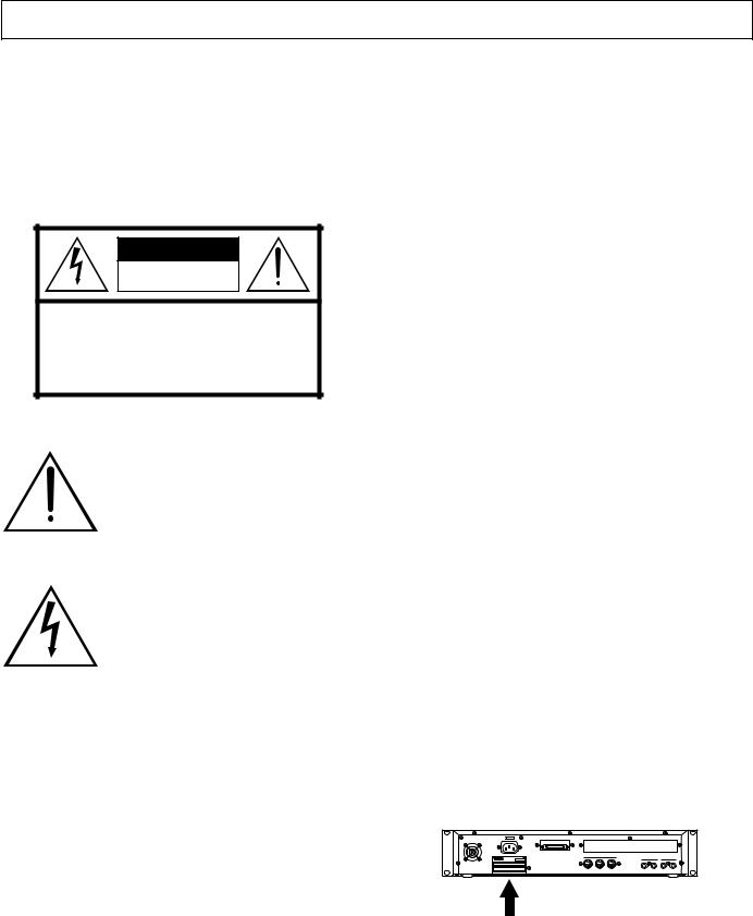
PRODUCT SAFETY MARKINGS: Yamaha electronic products may have either labels similar to the graphics shown below or molded/stamped facsimiles of these graphics on the enclosure. The explanation of these graphics appears on this page. Please observe all cautions indicated on this page and those indicated in the safety instruction section.
CAUTION |
RISK OF ELECTRIC SHOCK |
DO NOT OPEN |
CAUTION: TO REDUCE THE RISK OF ELECTRIC SHOCK. |
DO NOT REMOVE COVER (OR BACK). |
NO USER-SERVICEABLE PARTS INSIDE. |
REFER SERVICING TO QUALIFIED SERVICE PERSONNEL. |
The exclamation point within the equilateral triangle is intended to alert the user to the presence of important operating and maintenance (servicing) instructions in the literature accompanying the product.
The lightning flash with arrowhead symbol, within the equilateral triangle, is intended to alert the user to the presence of uninsulated “dangerous voltage” within the product’s enclosure that may be of sufficient magnitude to constitute a risk of electrical shock.
IMPORTANT NOTICE: All Yamaha electronic products are tested and approved by an independent safety testing laboratory in order that you may be sure that when it is properly installed and used in its normal and customary manner, all foreseeable risks have been eliminated. DO NOT modify this unit or commission others to do so unless specifically authorized by Yamaha. Product performance and/or safety standards may be diminished. Claims filed under the expressed warranty may be denied if the unit is/has been modified. Implied warranties may also be affected.
SPECIFICATIONS SUBJECT TO CHANGE: The information contained in this manual is believed to be correct at the time of printing. However, Yamaha reserves the right to change or modify any of the specifications without notice or obligation to update existing units.
ENVIRONMENTAL ISSUES: Yamaha strives to produce products that are both user safe and environmentally friendly. We sincerely believe that our products and the production methods used to produce them, meet these goals. In keeping with both the letter and the spirit of the law, we want you to be aware of the following:
Battery Notice: This product MAY contain a small nonrechargable battery which (if applicable) is soldered in place. The average life span of this type of battery is approximately five years. When replacement becomes necessary, contact a qualified service representative to perform the replacement.
Warning: Do not attempt to recharge, disassemble, or incinerate this type of battery. Keep all batteries away from children. Dispose of used batteries promptly and as regulated by applicable laws. Note: In some areas, the servicer is required by law to return the defective parts. However, you do have the option of having the servicer dispose of these parts for you.
Disposal Notice: Should this product become damaged beyond repair, or for some reason its useful life is considered to be at an end, please observe all local, state, and federal regulations that relate to the disposal of products that contain lead, batteries, plastics, etc.
NOTICE: Service charges incurred due to lack of knowledge relating to how a function or effect works (when the unit is operating as designed) are not covered by the manufacturer’s warranty, and are therefore the owners responsibility. Please study this manual carefully and consult your dealer before requesting service.
NAME PLATE LOCATION: The graphic below indicates the location of the name plate. The model number, serial number, power requirements, etc., are located on this plate. You should record the model number, serial number, and the date of purchase in the spaces provided below and retain this manual as a permanent record of your purchase.
Rear Panel
Model _____________________________________
Serial No. __________________________________
Purchase Date ______________________________
92-469-
PRECAUTIONS
PLEASE READ CAREFULLY BEFORE PROCEEDING
* Please keep these precautions in a safe place for future reference.
 WARNING
Always follow the basic precautions listed below to avoid the possibility of serious injury or even death from electrical shock, short-circuiting, damages, fire or other hazards. These precautions include, but are not limited to, the following:
•This instrument contains no user-serviceable parts. Do not attempt to disassemble or modify the internal components in any way.
•Do not expose the instrument to rain, use it near water or in damp or wet conditions, or place containers on it containing liquids which might spill into any openings.
•If the power cord or plug becomes frayed or damaged, or if there is a sudden loss of sound during use of the instrument, or if any unusual smells or smoke should appear to be caused by it, immediately turn off the power switch, disconnect the electric plug from the outlet, and have the instrument inspected by qualified Yamaha service personnel.
•Only use the voltage specified as correct for the instrument. The required voltage is printed on the name plate of the instrument.
•Always connect the three-pin attachment plug to a properly grounded power source. (For more information about the main power supply, see “Connecting the Power.)
•Before cleaning the instrument, always remove the electric plug from the outlet. Never insert or remove an electric plug with wet hands.
•Check the electric plug periodically and remove any dirt or dust which may have accumulated on it.
 CAUTION
Always follow the basic precautions listed below to avoid the possibility of physical injury to you or others, or damage to the instrument or other property. These precautions include, but are not limited to, the following:
•Do not place the power cord near heat sources such as heaters or radiators, and do not excessively bend or otherwise damage the cord, place heavy objects on it, or place it in a position where anyone could walk on, trip over, or roll anything over it.
•When removing the electric plug from an outlet, always hold the plug itself and not the cord. Pulling by the cord can damage it.
•Do not connect the instrument to an electrical outlet using a multiple-con- nector. Doing so can result in lower sound quality, or possibly cause overheating in the outlet.
•Remove the electric plug from the outlet when the instrument is not to be used for extended periods of time, or during electrical storms.
•Before connecting the instrument to other electronic components, turn off the power for all components. Before turning the power on or off for all components, set all volume levels to minimum.
•Do not expose the instrument to excessive dust or vibrations, or extreme cold or heat (such as in direct sunlight, near a heater, or in a car during the day) to prevent the possibility of panel disfiguration or damage to the internal components.
•Do not use the instrument near other electrical products such as televisions, radios, or speakers, since this might cause interference which can affect proper operation of the other products.
•Do not place the instrument in an unstable position where it might accidentally fall over.
■Handling and Installation of Options
 WARNING
•Before beginning installation, switch off the power to the A3000 and connected peripherals, and unplug them from the power outlet. Then remove all cables connecting the A3000 to other devices. (Leaving the power cord connected while working can result in electric shock. Leaving other cables connected can interfere with work.)
•Do not disassemble, modify, or apply excessive force to board areas and connectors on option boards, hard disk, and SIMMs. Bending or tampering with boards and connectors may lead to electric shock, fire, or equipment failures.
•Before moving the instrument, remove all connected cables.
•When cleaning the instrument, use a soft, dry cloth. Do not use paint thinners, solvents, cleaning fluids, or chemical-impregnated wiping cloths. Also, do not place vinyl or plastic objects on the instrument, since this might discolor the panel.
•Do not rest your weight on, or place heavy objects on the instrument, and do not use excessive force on the buttons, switches or connectors.
•Do not place objects in front of the instrument's air vent, since this may prevent adequate ventilation of the internal components, and possibly result in the instrument overheating. To ensure adequate ventilation and cooling, leave at least 10cm of open space behind the A3000 rear panel, and at least 4cm of open space above the top cover.
•Do not operate the instrument for a long period of time at a high or uncomfortable volume level, since this can cause permanent hearing loss. If you experience any hearing loss or ringing in the ears, consult a physician.
■SAVING USER DATA
•To protect against data loss caused by malfunction or operating error, be sure to save your data regularly to floppy disk, hard disk or other storage medium.
Yamaha cannot be held responsible for damage caused by improper use or modifications to the instrument, or data that is lost or destroyed.
Always turn the power off when the instrument is not in use.
CAUTION
•Before handling an option board, hard disk, or SIMM, you should briefly touch the A3000 metal casing (or other such metallic area) with your bare hand so as to drain off any static charge from your body. Note that even a slight amount of electrostatic discharge may cause damage to these components.
•It is recommended that you wear gloves to protect your hands from metallic projections on the A3000, hard disk, SIMMs, option boards, and other components. Touching leads or connectors with bare hands may cause finger cuts, and may also result in poor electrical contact or electrostatic damage.
•Take care to avoid dropping screws into the A3000 unit. If a screw does fall in, be sure to remove it before you reassemble and power up the unit. Starting the unit with a loose screw inside may lead to improper operation or equipment failure. (If you are unable to retrieve a dropped screw, consult your Yamaha dealer for advice.)
*Consult your Yamaha dealer if you have any questions regarding installation procedures for options boards, hard disks, SIMMs, or other optional devices.
*If SIMM memory, hard disk, or other optional component fails to work properly, consult the item's dealer for advice.

Features
Features
Versatile Professional Sampler
The A3000 professional sampler is an ideal break-beat machine and phrase sampler for a wide variety of recording and performance applications.
Excellent Effects System
The A3000’s triple-block effect system lets you set up as many as three independent effects. Select from a wide range of built-in effects — including original effects custom-designed to heighten the performance qualities of phrase and break-beat play. You can also apply effects to incoming signals as you record them, and to analog input that you feed through the A3000 for realtime output.
Easy to Use
The A3000 presents its editing and control capabilities in an easy-to-use three-level arrangement. All operations are handled using front-panel mode buttons, function keys, and knobs. You can access and edit any setting by selecting the mode, then selecting the function, and then turning the knobs directly under the screen. It is also possible to use knobs and function keys to control realtime playback.
Performance-Enhancing Options
Installation of the optional I/O expansion board (AIEB1 board) adds digital I/O capability plus six additional as- signable-output pairs to your A3000. The A3000 also accepts up to 128MB of expansion memory.
List of Accessories
Your A3000 package includes the following accessories. Make sure that all of these accessories are included.
•CD-ROM
•Power cord
•MIDI cable
•Five floppy disks
•Owner’s Manual
•Power supply cable for hard disk (red/white 4-wire cable)
•SCSI cable for hard disk
*If any of the above items is missing, please contact your Yamaha dealer for assistance.
Unauthorized copying of copyrighted software for purposes other than purchaser’s personal use is prohibited.
2

Features
PROFESSIONAL SAMPLER
Owner’s Manual
Thank you for your purchase of the Yamaha A3000 Professional Sampler. The A3000 incorporates a leading-edge AWM2 tone generator, and is an ideal for use with synthesizers, MIDI keyboards, and other MIDI devices in a wide variety of musical applications.
This owner’s manual will help you get the most from your A3000’s many advanced features. Please read through the essential parts of the manual carefully before beginning work with your sampler, and refer back to the manual for additional information as necessary. Please be sure to store the manual in a safe and handy location.
3

Contents
Contents
Using the Manual .............................................................................. |
6 |
Panel and Connector Arrangement .................................................. |
8 |
A3000 Options ................................................................................. |
14 |
Handling the Floppy Disk Drive(FDD) and Floppy Disk ............... |
16 |
Chapter 1 Setting Up |
|
Setting Up ........................................................................................ |
20 |
Connecting the Power .................................................................... |
21 |
Connecting the A3000 Outputs ...................................................... |
22 |
Connecting the Audio Inputs ......................................................... |
25 |
MIDI Connections ........................................................................... |
27 |
Power ON/OFF ................................................................................ |
30 |
Sound Check ................................................................................... |
32 |
Chapter 2 Trying It Out |
|
Introduction .................................................................................... |
36 |
Starting Out .................................................................................... |
38 |
Next Step ......................................................................................... |
45 |
Sample Editing ................................................................................ |
52 |
Program Editing ............................................................................. |
57 |
Sequence Play ................................................................................. |
62 |
Saving and Reloading Your Data .................................................... |
64 |
Accompanying Disks ....................................................................... |
68 |
Chapter 3 Basics |
|
Samples and Programs ................................................................... |
70 |
Sample Output Destinations and Effects ....................................... |
78 |
Data Configuration and Handling .................................................. |
80 |
Modes and Functions ...................................................................... |
84 |
Basic Operation ............................................................................... |
86 |
Other Keys and Operations ............................................................. |
91 |
Chapter 4 PLAY Mode |
|
Play Mode ........................................................................................ |
94 |
Program & Sample Selection Screen ............................................. |
95 |
PROGRAM/SAMPLE Selection Screen ................................................... |
95 |
COMMAND Pages ............................................................................ |
98 |
SAVE ........................................................................................................ |
98 |
INIT (Program Initialization) ............................................................... |
101 |
COPY ..................................................................................................... |
102 |
PGMDUMP (Program Dump) .............................................................. |
103 |
SETINIT (Set Program’s Initial Conditions) ........................................ |
104 |
NEWBANK (Create a Sample Bank) ..................................................... |
105 |
DELETE ................................................................................................ |
106 |
DUPL (Duplicate) .................................................................................. |
107 |
SMPDUMP (Sample Dump) .................................................................. |
108 |
PROGRAM Function ..................................................................... |
110 |
PROGRAM - PgmSel (Select Program) ................................................ |
110 |
SAMPLE Function ........................................................................ |
112 |
SAMPLE - SmpSel (Select Sample) ...................................................... |
112 |
SAMPLE - SmpBnk (Select Sample from Sample Bank) .................... |
114 |
SAMPLE - ToBank (Assign Sample to Bank) ....................................... |
115 |
SAMPLE - SmpSort (Sort Samples) ..................................................... |
117 |
EASY EDIT Function .................................................................... |
118 |
EASY EDIT - EasyEd ............................................................................. |
119 |
EFFECT Function ......................................................................... |
121 |
EFFECT - EfType (Select the Effect Types) .......................................... |
121 |
EFFECT - Efct1,...,Efct3 (Edit the Effects) .......................................... |
124 |
EFFECT - In&Out (Input/output levels and pan) ................................ |
126 |
EFFECT - EdType (Effect Edit Type) .................................................... |
127 |
SETUP Function ........................................................................... |
128 |
SETUP - PgmMstr (Program’s Master Settings) .................................. |
128 |
SETUP - Portmnt (Portamento) ........................................................... |
130 |
SETUP - ADSetup (A/D-In Setup) ........................................................ |
132 |
SETUP - ADOut (Output Setup for A/D-Input Signal) ........................ |
134 |
CONTROL Function ...................................................................... |
136 |
CONTROL - PgmCtl1 (Program Controller Setup 1) .......................... |
136 |
CONTROL - PgmCtl2 (Program Controller Setup 2) .......................... |
139 |
CONTROL - Reset (Controller Reset) ................................................... |
141 |
Chapter 5 EDIT Mode |
|
EDIT Mode .................................................................................... |
144 |
COMMAND Pages .......................................................................... |
147 |
SAVE ...................................................................................................... |
147 |
REVERT ................................................................................................. |
149 |
NORM (Normalize) ............................................................................... |
150 |
RESMPL - TmStrch (Resampling - Time Stretch) .............................. |
151 |
RESMPL - PtchCnv (Resampling - Pitch Conversion) ........................ |
153 |
FADE ..................................................................................................... |
155 |
REVERS (Reverse) ................................................................................ |
157 |
LOOPXFD (Loop Crossfade) ................................................................. |
158 |
SETINIT (Register Initial Parameter Values) ....................................... |
160 |
TRIM/LOOP Function ................................................................... |
161 |
TRIM/LOOP - Config (Configure) ......................................................... |
161 |
TRIM/LOOP - Wave (Edit Waveform) ................................................... |
164 |
TRIM/LOOP - Loop (Edit Loop Addresses) ........................................... |
166 |
TRIM/LOOP - WvMode (Set Wave Mode) ............................................. |
168 |
MAP/OUT Function ....................................................................... |
170 |
MAP/OUT - KeyRnge (Key Range) ........................................................ |
170 |
MAP/OUT - VelRnge (Velocity Range) .................................................. |
172 |
MAP/OUT - Lvl&Mode ........................................................................... |
174 |
MAP/OUT - Output ................................................................................ |
176 |
MAP/OUT - Pitch ................................................................................... |
178 |
MAP/OUT - Expand ............................................................................... |
179 |
MAP/OUT - LvlScale (Level Scaling) .................................................... |
180 |
FILTER Function .......................................................................... |
182 |
FILTER - Filter ...................................................................................... |
182 |
FILTER - FltSens (Filter Sensitivity) ................................................... |
184 |
FILTER - FltScale (Filter Scaling) ........................................................ |
185 |
FILTER - EQ (Equalization) ................................................................. |
187 |
EG Function .................................................................................. |
188 |
EG - AEG (Amplitude Envelope Generator) ......................................... |
188 |
EG - AEGMode (AEG Mode Settings) ................................................... |
190 |
EG - FEGRate (Filter-EG Rates) ........................................................... |
192 |
EG - FEGLevel (Filter-EG Levels) ........................................................ |
194 |
EG - FEGMode (FEG Mode Settings) ................................................... |
196 |
EG - PEGRate (Pitch-EG Rates) ........................................................... |
198 |
EG - PEGLevel (Pitch-EG Levels) ........................................................ |
200 |
4

Contents
EG - PEGMode (PEG Mode Settings) ................................................... |
201 |
LFO Function ................................................................................ |
203 |
LFO - Common ..................................................................................... |
203 |
LFO - FltrMod (Filter Modulation) ...................................................... |
205 |
LFO - PtchMod (Pitch Modulation)...................................................... |
206 |
LFO - AmpMod (Amplitude Modulation) ............................................. |
207 |
MIDI/CTRL Function .................................................................... |
208 |
MIDI/CTRL - RCh&Alt (Receive Channel and Alternate ..................... |
208 |
MIDI/CTRL - SmpCtl1 (Sample Controller Setup 1) ........................... |
210 |
MIDI/CTRL - SmpCtl2 (Sample Controller Setup 2) ........................... |
213 |
MIDI/CTRL - Vel&PB (Velocity and Pitchbend) ................................... |
215 |
Chapter 6 RECORDING Mode |
|
RECORDING Mode ....................................................................... |
220 |
COMMAND Page ........................................................................... |
221 |
SAVE ...................................................................................................... |
221 |
RECORD Function ........................................................................ |
223 |
RECORD - Record ................................................................................. |
223 |
SETUP Function ........................................................................... |
227 |
SETUP - RecData .................................................................................. |
227 |
SETUP - Target ...................................................................................... |
230 |
SETUP - KeyRnge ................................................................................. |
232 |
SETUP - Trigger .................................................................................... |
234 |
SETUP - Process.................................................................................... |
235 |
METER Function .......................................................................... |
236 |
METER - Meter ..................................................................................... |
236 |
METER - TrgLvl .................................................................................... |
237 |
EFFECT Function ......................................................................... |
238 |
EFFECT - EfType (Select the Effect Types) ........................................ |
238 |
EFFECT - RecEf1,...,RecEf3 (Edit the Effects) .................................... |
239 |
EFFECT - In&Out (Input/output levels and pan) ................................ |
240 |
EFFECT - EdType (Effect Edit Type) .................................................... |
240 |
EXT CTRL Function ..................................................................... |
241 |
EXT CTRL - CD-ROM ........................................................................... |
241 |
EXT CTRL - CD-DA ............................................................................... |
242 |
MONITOR Function ...................................................................... |
243 |
MONITOR - Monitor ............................................................................. |
243 |
MONITOR - Click .................................................................................. |
245 |
Chapter 7 DISK Mode |
|
DISK Mode .................................................................................... |
248 |
COMMAND Pages .......................................................................... |
249 |
LOAD ..................................................................................................... |
249 |
DELETE ................................................................................................ |
250 |
COPY ..................................................................................................... |
251 |
FORMAT ................................................................................................ |
252 |
PHYS_FMT (Physical Format) ............................................................. |
254 |
PART_FMT (Format a Partition) .......................................................... |
256 |
FD_FMT (Format a Floppy Disk) ......................................................... |
258 |
PROGRAM Function ..................................................................... |
259 |
PROGRAM - PgmLoad (Load Program(s)) ........................................... |
259 |
SAMPLE Function ........................................................................ |
261 |
SAMPLE - SmpLoad (Load Sample(s)) ................................................ |
261 |
SEQUENCE Function ................................................................... |
264 |
SEQUENCE - SeqLoad (Load Sequence(s)) ......................................... |
264 |
VOLUME Function ........................................................................ |
266 |
VOLUME - Volume ................................................................................ |
266 |
DISK Function .............................................................................. |
268 |
DISK - Disk ........................................................................................... |
268 |
DISK - Config (Configure) .................................................................... |
270 |
DISK - SelfID ........................................................................................ |
271 |
IMPORT Function ......................................................................... |
272 |
IMPORT - ImpSmp (Import a sample) ................................................. |
272 |
IMPORT - ImpVce (Import a voice) ...................................................... |
274 |
IMPORT - ImpOthr (Import Other Data Type) .................................... |
276 |
Chapter 8 UTILITY Mode |
|
UTILITY Mode ............................................................................... |
280 |
COMMAND Pages .......................................................................... |
281 |
SAVE ...................................................................................................... |
281 |
DELETE ................................................................................................ |
283 |
SAVESYS (Save System Settings)......................................................... |
284 |
LOADSYS (Load System Settings) ....................................................... |
285 |
ALLDUMP (Data Dump) ....................................................................... |
286 |
TOTAL EQ Function ..................................................................... |
287 |
Total EQ - Gain ...................................................................................... |
288 |
Total EQ - Freq ...................................................................................... |
289 |
Total EQ - Width ................................................................................... |
290 |
PANEL PLAY Function .................................................................. |
291 |
PANEL PLAY - KnobCtl (Knob Control) .............................................. |
291 |
PANEL PLAY - KnobSet ........................................................................ |
292 |
PANEL PLAY - FKeySet (Set Function Keys) ....................................... |
294 |
SEQUENCE Function ................................................................... |
296 |
SEQUENCE - SeqSel (Select Sequence) .............................................. |
296 |
SEQUENCE - Play&Rec (Playback and Recording) ............................. |
297 |
MASTER Function ........................................................................ |
298 |
MASTER - Tuning ................................................................................. |
298 |
MASTER - StOut (Stereo Output Assignment) .................................... |
299 |
SYSTEM Function ........................................................................ |
300 |
SYSTEM - Keys ..................................................................................... |
300 |
SYSTEM - Display ................................................................................. |
302 |
SYSTEM - Page ..................................................................................... |
303 |
SYSTEM - FreeMem .............................................................................. |
304 |
MIDI Function .............................................................................. |
305 |
MIDI - Receive ....................................................................................... |
305 |
MIDI - Adjust ......................................................................................... |
307 |
MIDI - RcvFlt (Receiving Filter) ........................................................... |
309 |
MIDI - Bulk (Bulk Dump) ..................................................................... |
310 |
Appendix |
|
Installing SIMMs ........................................................................... |
312 |
Installing the AIEB1 I/O Expansion Board .................................. |
316 |
Setting the SCSI Board Terminator Switch ................................. |
320 |
Installing an Internal Hard Disk .................................................. |
323 |
Connecting external SCSI devices ................................................ |
328 |
Specifications ................................................................................ |
332 |
Effect type list ............................................................................... |
335 |
Effect parameter list ..................................................................... |
337 |
Control change number list ......................................................... |
347 |
Troubleshooting ............................................................................ |
348 |
Error messages .............................................................................. |
351 |
MIDI data format ........................................................................... |
352 |
Index |
|
Index .............................................................................................. |
364 |
5

Using the Manual
Using the Manual
Manual Organization
This manual comprises eight chapters and an Appendix. Chapters 1 and 3 contain essential information and should be read carefully. You may also wish to run through the brief tutorial given in Chapter 2 before beginning serious work with the A3000.
Chapters 4 through 8 provide detailed information about each of the five operating modes. Refer to this information as needed while working with the A3000.
■Chapter 1 Setting Up
This chapter explains the A3000’s controls and connectors, and shows how to connect up speakers and MIDI devices. Please read through this chapter before you start to work with the A3000.
■Chapter 2 Trying It Out
This chapter guides you through a trial run with the A3000. Going through these procedures will help you get a good feel for basic A3000 operations.
■Chapter 3 Basics
The chapter introduces basic concepts, terminology, and operating procedures. Read this chapter to learn about samples, sample banks, programs, and sequences; modes and functions; screen displays; and other important features.
■Chapter 4 PLAY Mode
This chapter explains all PLAY-mode functions. You use PLAY mode to edit and play programs.
■Chapter 5 EDIT Mode
This chapter explains all EDIT-mode functions. You use EDIT mode to edit your samples and sample banks.
■Chapter 6 RECORDING Mode
This chapter explains all RECORDING-mode functions. You use RECORDING mode to record samples and sequences.
■Chapter 7 DISK Mode
This chapter explains all DISK-mode functions. You use DISK mode to manage your floppy and hard disks.
■Chapter 8 UTILITY Mode
This chapter explains all UTILITY-mode functions. You use UTILITY mode to set the system’s environment.
■Appendix
Provides option installation instructions, troubleshooting advice, error-message descriptions, A3000 specifications, and MIDI information.
6

Using the Manual
Finding the Information You Need
You can use any of the following methods to locate information within this manual.
Use the Contents.
Check the Contents on pages 4 to 6.
Use the Index.
Refer to the Index on pages 363 to 367.
Refer to Panel and Connector Arrangement.
Go to the “Panel and Connector Arrangement” section (pages 8 to 14) and locate the knob, key, or other component that you require information about. Then refer to the indicated page.
Leaf through the manual.
Page through sections related to the feature you need information about. Note that each page has a header indicating the page’s contents, and a footer indicating the chapter name.
Icons
This manual uses the following icons to call attention to specific types of information.
Important: An important note or precaution intended to help you avoid loss of data or other major inconvenience. Always read these notices carefully.
FYI (For Your Information): Reference information indirectly related to the content of the main text. May contain practical advice or general supplementary information.
Procedure: Step-by-step instructions for carrying out a particular operation. A mark within a procedure indicates the result produced by carrying out the immediately preceding instruction.
xx Page reference. Directs you to another page for related information.
Screen illustrations and other drawings within this manual are for explanatory purposes only, and may in some cases differ from actual displays and configurations.
7

Panel and Connector Arrangement
 Panel and Connector Arrangement
Front Panel (Left Side)
|
(2) |
|
|
(5) |
|
|
MASTER VOL |
REC VOL |
|
|
|
|
|
(1) |
|
|
|
|
|
|
PHONES |
L INPUT |
R |
|
|
|
|
|
|
1 |
2 |
3 |
4 |
5 |
(3) |
(4) |
(6) |
(7) |
(1) MASTER VOL (Master Volume)
Adjusts the output level at the STEREO OUT connectors only. This knob does not affect the output level at the ASSIGNABLE OUT connectors, or at the various connectors provided on the optional I/O expansion board (AIEB1 board).
8
Panel and Connector Arrangement
(2) REC VOL (Recording Volume)
Adjusts the input level from the front panel’s INPUT L and INPUT R jacks. Use the knob to adjust the level when recording a sample, or when passing an input signal directly through the A3000 outputs for realtime output (“A/D In” feature).
This knob does not affect the input level to the DIGITAL IN and OPTICAL IN connectors on the optional I/O expansion board (AIEB1 board).
(3) PHONES jack
Connects to a set of stereo headphones. The PHONES jack always produces the same signal as the STEREO OUT jacks. Note that headphone impedance should be between 16 and 150 ohms.
(4) INPUT L, INPUT R jacks
Use these jacks to input an analog signal for recording, or for realtime output (“A/D In” feature). Use the INPUT L jack if you are supplying a monaural signal.
(5) Display
The display indicates the status and settings for the currently selected function, and presents messages and confirmation prompts. When you are working at a parametersetting page, the top line of the display indicates the parameter names, while the bottom line shows the current values. The names and values appear directly over the knobs that you use to make the settings.
(6) Knob “push” lamps
The lamp above the knob lights up to indicate that the knob can be pushed to execute some action. If the lamp is off, pushing the knob has no effect.
(7) Knobs
You use the knobs to set the various parameter values, to switch display pages, and execute operations. In most cases you turn the knob to set a value, and push the knob to execute an operation — for example, to start or stop recording. Knobs are numbered 1 to 5.
9
Panel and Connector Arrangement
Front Panel (Right Side)
(1) |
|
(2) |
|
|
|
|
|
|
|
|
|
|
|
|
|
|
|
POWER |
|
PLAY |
|
|
|
|
|
|
|
|
|
EDIT |
PROGRAM |
SAMPLE |
|
EASY EDIT |
EFFECT |
SETUP |
CONTROL |
|
(7) |
|
TRIM/LOOP |
MAP/OUT |
|
FILTER |
EG |
LFO |
MIDI/CTRL |
|
|
REC |
RECORD |
SETUP |
|
METER |
EFFECT |
EXIT CTRL |
MONITOR |
|
|
PROGRAM |
SAMPLE |
|
SEQUENCE |
VOLUME |
DISK |
IMPORT |
ON/ |
OFF |
|
|
|
||||||||
|
TOTAL EQ |
PANEL PLAY |
SEQUENCE |
MASTER |
SYSTEM |
MIDI |
|||
|
|
|
|||||||
DISK |
|
|
|
|
|
|
|
|
|
UTILITY |
|
|
|
|
|
|
|
|
|
|
COMMAND |
ASSIGNABLE |
AUDITION |
|
|
|
|
|
|
|
(3) |
(4) |
|
(5) |
|
|
(6) |
|
|
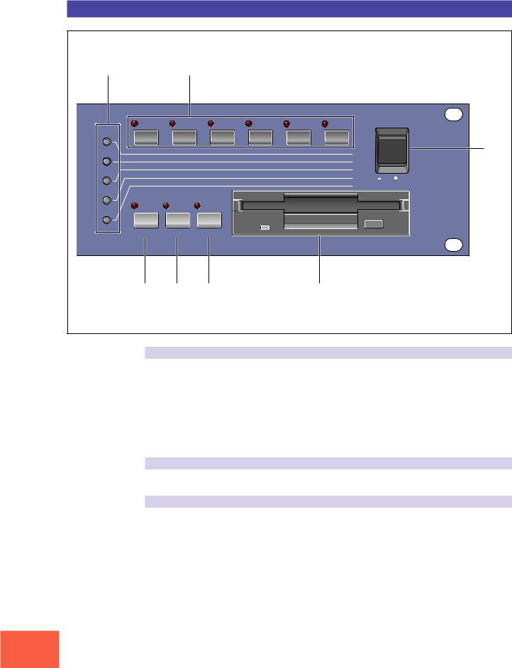
(1) Mode buttons
The A3000 provides five operating modes. You select the mode by pressing the corresponding mode button. The button lamp comes on to indicate that the mode is selected.
Each mode is further divided into six functions. After selecting the mode, you can switch among its functions by pressing the appropriate function keys.
(The A3000 also uses the button lamps to let you know that it is receiving MIDI data. Each lamp corresponds to a different MIDI data type, and will continue to blink while the A3000 is receiving MIDI data of that type. ( 92))
(2) Function keys
Use these keys to switch among the six functions within the currently selected mode.
(3) COMMAND key
You press the COMMAND key to access additional commands relevant to the mode and function that you are currently working in. ( 91)
10

Panel and Connector Arrangement
(4) ASSIGNABLE key
You can assign this key any of four different functions. You can set it to operate as a damp key (so that it switches all sound off), as a controller reset button, or as a toggle for the knob-controller feature (knobs act as controllers) or the function-key playback feature (function keys act as MIDI keys). ( 91)
(5) AUDITION key
Press the key to play out the currently selected sample. You use this feature to check the sound of the sample while editing.
(6) Floppy-disk drive
Accepts a 3.5-inch floppy disk. You can use floppy disks to save and reload your data (programs, samples, sequences, and system settings).
Note that there is an access lamp at the lower left of the drive. The lamp lights up while the disk is being accessed. Please do not eject the floppy-disk while this lamp is on.
To eject a disk, press the EJECT button at the lower right of the drive.
(7) POWER switch
Press once to switch the power on. Press again to turn the power off.
Important
The A3000 stores all new data into main memory only, and will lose all of this data when you switch off the power. You must therefore be sure to save all important data to disk before turning the A3000 off.
11
Panel and Connector Arrangement
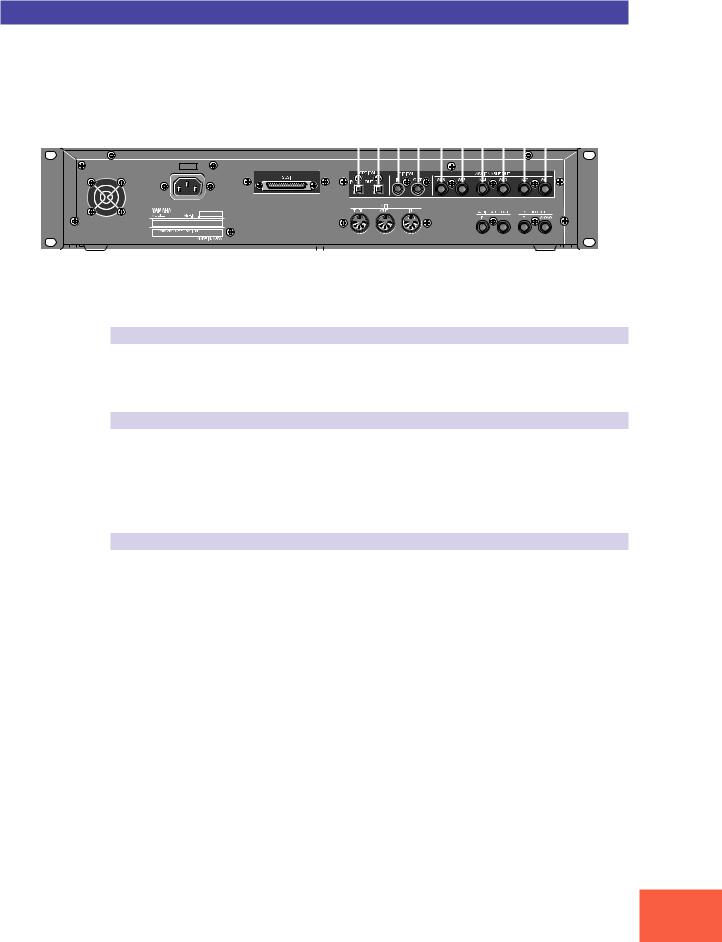
Rear Panel
(5)
|
|
|
|
|
|
|
|
|
|
|
|
|
|
|
|
|
|
|
|
|
|
|
|
|
|
|
|
|
|
|
|
|
|
|
|
|
|
|
|
|
|
|
|
|
|
|
|
|
|
|
|
|
|
|
|
|
|
|
|
|
|
|
|
|
|
|
|
|
|
|
|
|
|
|
|
|
|
|
|
|
|
|
|
|
|
|
|
|
|
|
|
|
|
|
|
|
|
|
|
|
|
|
|
|
|
|
|
|
|
|
|
|
|
|
|
|
|
|
|
|
|
|
|
|
|
|
|
|
|
|
|
|
|
|
|
|
|
|
|
|
|
|
|
|
|
|
|
|
|
|
|
|
|
|
|
|
|
|
|
|
|
|
|
|
|
|
|
|
|
|
|
|
|
|
|
|
|
|
|
|
|
|
|
|
|
|
|
|
|
|
|
|
|
|
|
|
|
|
|
|
|
|
|
|
|
|
|
|
|
|
|
|
|
|
|
|
|
|
|
|
|
|
|
|
|
|
|
|
|
|
|
|
|
|
|
|
|
|
|
|
|
|
|
|
|
|
|
|
|
|
|
|
|
|
|
|
|
|
|
|
|
|
|
|
|
|
|
|
|
|
|
|
|
|
|
|
|
|
|
|
|
|
|
|
|
|
|
|
|
|
|
|
|
|
|
|
|
|
|
|
|
|
|
|
|
|
|
|
|
|
|
|
|
|
|
|
|
|
|
|
|
|
|
|
|
|
|
|
|
|
|
|
|
|
|
|
|
|
|
|
|
|
|
|
|
|
|
|
|
|
|
|
|
|
|
|
|
|
|
|
|
|
|
|
|
|
|
|
|
|
|
|
|
|
|
|
|
|
|
|
|
|
|
|
|
|
|
|
|
|
|
|
|
|
|
|
|
|
|
|
|
|
|
|
|
|
|
|
|
|
|
|
|
|
|
|
|
|
|
|
|
|
|
|
|
|
|
|
|
|
|
|
|
|
|
|
|
|
|
|
|
|
|
|
|
|
|
|
|
|
|
|
|
|
|
|
|
|
|
|
|
|
|
|
|
|
|
|
|
|
|
|
|
|
|
|
|
|
|
|
|
|
|
|
|
|
|
|
|
|
|
|
|
|
|
|
|
|
|
|
|
|
|
|
|
|
|
|
|
|
|
|
|
|
|
|
|
|
|
|
|
|
|
|
|
|
|
|
|
|
|
|
|
|
|
|
|
|
|
|
|
|
|
|
|
|
|
|
|
|
|
|
|
|
|
|
|
|
|
|
|
|
|
|
|
|
|
|
|
|
|
|
|
|
|
|
|
|
|
|
|
|
|
|
|
|
|
|
|
|
|
|
|
|
|
|
|
|
|
|
(1) |
(2) |
(3) |
(4) |
|
|
|
|
|
|
|
||||||||||||||||||
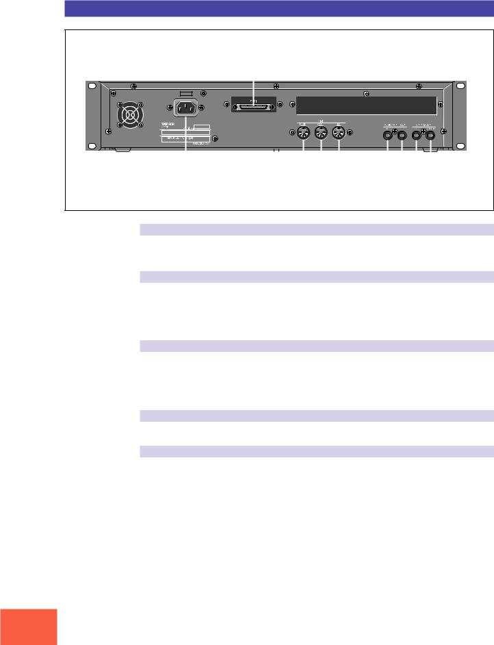
(1) AC inlet
Connects to the AC power cord supplied with the A3000. (Please do not use any other power cord with this unit.)
(2) MIDI connectors
These connectors link the A3000 to external MIDI devices. The MIDI IN connector receives MIDI signals, while the MIDI OUT connector transmits MIDI data generated by the A3000. The MIDI THRU connector relays the MIDI signals received at the MIDI IN connector.
(3) ASSIGNABLE OUT jacks
Analog output jacks. These jacks operate independently of the STEREO OUT jacks. You can use these jacks to output the sound of one or more selected samples, or to output the signal supplied through the front panel’s analog input connectors ( 134, 176). You may also set them so that they output the same signal as the STEREO OUT jacks ( 299).
(4) STEREO OUT jacks
These are the main analog output jacks.
(5) SCSI connector
This is a half-pitch 50-pin connector. You use it to connect up a SCSI hard drive, CDROM drive, or other SCSI device.
12
Panel and Connector Arrangement
Rear Panel (with optional AIEB1 board installed)
|
(1) |
(2) |
(3) |
|
|
|
|
|
|
|
|
|
|
|
|
|
|
||||||||||||||||||||||||||||||||||
|
|
|
|
|
|
|
|
|
|
|
|
|
|
|
|
|
|
|
|
|
|
|
|
|
|
|
|
|
|
|
|
|
|
|
|
|
|
|
|
|
|
|
|
|
|
|
|
|
|
|
|
|
|
|
|
|
|
|
|
|
|
|
|
|
|
|
|
|
|
|
|
|
|
|
|
|
|
|
|
|
|
|
|
|
|
|
|
|
|
|
|
|
|
|
|
|
|
|
|
|
|
|
|
|
|
|
|
|
|
|
|
|
|
|
|
|
|
|
|
|
|
|
|
|
|
|
|
|
|
|
|
|
|
|
|
|
|
|
|
|
|
|
|
|
|
|
|
|
|
|
|
|
|
|
|
|
|
|
|
|
|
|
|
|
|
|
|
|
|
|
|
|
|
|
|
|
|
|
|
|
|
|
|
|
|
|
|
|
|
|
|
|
|
|
|
|
|
|
|
|
|
|
|
|
|
|
|
|
|
|
|
|
|
|
|
|
|
|
|
|
|
|
|
|
|
|
|
|
|
|
|
|
|
|
|
|
|
|
|
|
|
|
|
|
|
|
|
|
|
|
|
|
|
|
|
|
|
|
|
|
|
|
|
|
|
|
|
|
|
|
|
|
|
|
|
|
|
|
|
|
|
|
|
|
|
|
|
|
|
|
|
|
|
|
|
|
|
|
|
|
|
|
|
|
|
|
|
|
|
|
|
|
|
|
|
|
|
|
|
|
|
|
|
|
|
|
|
|
|
|
|
|
|
|
|
|
|
|
|
|
|
|
|
|
|
|
|
|
|
|
|
|
|
|
|
|
|
|
|
|
|
|
|
|
|
|
|
|
|
|
|
|
|
|
|
|
|
|
|
|
|
|
|
|
|
|
|
|
|
|
|
|
|
|
|
|
|
|
|
|
|
|
|
|
|
|
|
|
|
|
|
|
|
|
|
|
|
|
|
|
|
|
|
|
|
|
|
|
|
|
|
|
|
|
|
|
|
|
|
|
|
|
|
|
|
|
|
|
|
|
|
|
|
|
|
|
|
|
|
|
|
|
|
|
|
|
|
|
|
|
|
|
|
|
|
|
|
|
|
|
|
|
|
|
|
|
|
|
|
|
|
|
|
|
|
|
|
|
|
|
|
|
|
|
|
|
|
|
|
|
|
|
|
|
|
|
|
|
|
|
|
|
|
|
|
|
|
|
|
|
|
|
|
|
|
|
|
|
|
|
|
|
|
|
|
|
|
|
|
|
|
|
|
|
|
|
|
|
|
|
|
|
|
|
|
|
|
|
|
|
|
|
|
|
|
|
|
|
|
|
|
|
|
|
|
|
|
|
|
|
|
|
|
|
|
|
|
|
|
|
|
|
|
|
|
|
|
|
|
|
|
|
|
|
|
|
|
|
|
|
|
|
|
|
|
|
|
|
|
|
|
|
|
|
|
|
|
|
|
|
|
|
|
|
|
|
|
|
|
|
|
|
|
|
|
|
|
|
|
|
|
|
|
|
|
|
|
|
|
|
|
|
|
|
|
(1) OPTICAL IN, OUT connectors
Use these connectors to input or output digital signals over optical-fiber cable. You can use the OPTICAL IN to record a digital signal of frequency 48kHz, 44.1kHz, or 32kHz. The OPTICAL OUT connector outputs a digital signal of frequency 44.1kHz.
(2) DIGITAL IN, OUT connectors
Use these connectors to input or output digital signals over coaxial (RCA-pin) cable. The digital signal format is CD/DAT (S/P DIF).
You can use the DIGITAL IN connector to record a digital signal of frequency 48kHz, 44.1kHz, or 32kHz. The DIGITAL OUT connector outputs a digital signal of frequency 44.1kHz.
(3) ASSIGNABLE OUT jacks (AS1 to AS6)
Additional analog output jacks. Each pair (1&2, 3&4, 5&6) operates independently of all other outputs on the A3000. You can use these jacks to output the sound of one or more selected samples, or to output the signal supplied through the front panel’s analog input connectors ( 134, 176). You may also set them so that they output the same signal as the STEREO OUT jacks ( 299).
13

A3000 Options
A3000 Options
You can enhance the capability of your A3000 by installing options. The A3000 supports two options: (1) additional memory, and (2) the AIEB1 board (I/O expansion board).
Expansion Memory (SIMMs)
The A3000 stores all active data in main memory. To play a sample back, you must first load it into main memory. And whenever you record a sample, you must record it into main memory.
Samples consume a great deal of memory. The A3000 comes standard with 2 megabytes (2MB) of memory — but this is only sufficient to store about 23 seconds of high-quality monaural sound (at 44.1kHz sampling frequency), or approximately 11.5 seconds of stereo sound.
You can increase this capacity by installing additional memory. The A3000 accepts expansion memory in the form of SIMMs (single in-line memory modules). Using SIMMs, you can install up to 128MB of memory onto the A3000. SIMMs can be purchased from almost any computer-supply dealer.
Adding memory will allow you to record longer samples, and to work with more samples at the same time. For information about how to install SIMMs, refer to the Appendix. ( 312)
Important
•You need to use 72-pin SIMMs with access time of 70ns or less. The SIMM module size may be 4MB, 8MB, 16MB, or 32MB. The A3000 is designed for use with 32-bit SIMMs, but can also accept installation of 36-bit (parity-type) SIMMs.
•SIMMs must be installed in pairs: you can install either two SIMMs or four SIMMs. Both modules in a pair must have the same memory capacity.
•The A3000 ships with 2MB of sampling memory installed, and is capable of accessing
up to 128MB. If you add one pair of 32MB SIMMs, for example, you increase the available sampling memory to a total of (2 + 32×2 =) 66MB. If you install four 32MB SIMMs, however, the sampling memory size becomes 128MB (and the original 2MB are effectively disabled).
•For more information about SIMM purchase, refer to your A3000 dealer.
14

A3000 Options
The I/O Expansion Board (AIEB1 Board)
In its standard configuration, the A3000 supports analog I/O only. Although it stores all internal data in digital form, it does not provide direct digital I/O connectors.
You can add digital I/O capacity by installing an AIEB1 board. The board offers two different digital connector types: optical connectors, and coaxial connectors. As an added benefit, the board also includes three stereo ASSIGNABLE OUTPUT pairs (six analog jacks), which operate independently of the standard STEREO OUT and ASSIGNABLE OUT jacks.
For information about how to install this board, refer to the Appendix. ( 312)
15

Handling the Floppy Disk Drive(FDD) and Floppy Disk
Handling the Floppy Disk Drive(FDD) and Floppy Disk
Precautions
Be sure to handle floppy disks and treat the disk drive with care. Follow the important precautions below.
Disk Type
The A3000 disk drive accepts 2HD-type and 2DD-type 3.5" floppy disks.
Inserting/Ejecting Floppy Disks
To insert a floppy disk into the disk drive:
Hold the disk so that the label of the disk is facing upward and the sliding shutter is facing forward, towards the disk slot. Carefully insert the disk into the slot, slowly pushing it all the way in until it clicks into place and the eject button pops out.
To eject a floppy disk:
Before ejecting the disk, be sure to confirm that the FDD is stopped (check if the LED below the floppy disk slot is off).
Press the eject button slowly as far as it will go; the disk will automatically pop out. When the disk is fully ejected, carefully remove it by hand.
Never attempt to remove the disk or turn the power off during reading or writing. Doing so can damage the disk and possibly the disk drive.
If the eject button is pressed too quickly, or if it is not pressed in as far as it will go, the disk may not eject properly. The eject button may become stuck in a half-pressed position with the disk extending from the drive slot by only a few millimeters. If this happens, do not attempt to pull out the partially ejected disk, since using force in this situation can damage the disk drive mechanism or the floppy disk. To remove a partially ejected disk, try pressing the eject button once again, or push the disk back into the slot and then repeat the eject procedure.
Be sure to remove the floppy disk from the disk drive before turning off the power. A floppy disk left in the drive for extended periods can easily pick up dust and dirt that can cause data read and write errors.
16

Handling the Floppy Disk Drive(FDD) and Floppy Disk
Cleaning the Disk Drive Read/Write Head
•Clean the read/write head regularly. This instrument employs a precision magnetic read/write head which, after an extended period of use, will pick up a layer of magnetic particles from the disks used that will eventually cause read and write errors.
•To maintain the disk drive in optimum working order Yamaha recommends that you use a commercially-available dry-type head cleaning disk to clean the head about once a month. Ask your Yamaha dealer about the availability of proper head-cleaning disks.
Never insert anything but floppy disks into the disk drive. Other objects may cause damage to the disk drive or floppy disks.
About the Floppy Disks
To handle floppy disks with care:
Do not place heavy objects on a disk or bend or apply pressure to the disk in any way. Always keep floppy disks in their protective cases when they are not in use.
Do not expose the disk to direct sunlight, extremely high or low temperatures, or excessive humidity, dust or liquids.
Do not open the sliding shutter and touch the exposed surface of the floppy disk inside.
Do not expose the disk to magnetic fields, such as those produced by televisions, speakers, motors, etc., since magnetic fields can partially or completely erase data on the disk, rendering it unreadable.
Never use a floppy disk with a deformed shutter or housing.
Do not attach anything other than the provided labels to a floppy disk. Also make sure that labels are attached in the proper location.
To protect your data (Write-protect Tab):
To prevent accidental erasure of important data, slide the disk’s write-protect tab to the “protect” position (tab open).
Data backup
For maximum data security Yamaha recommends that you keep two copies of important data on separate floppy disks. This gives you a backup if one disk is lost or damaged.
17

18
1
Chapter 1
Setting Up

Setting Up
Setting Up
This chapter explains how to set up your equipment and run a simple sound check.
Setup Sequence
This chapter takes you through each of the steps necessary to connect up your system.
Connecting the Power
Explains how to connect up the A3000’s power cord. ( 21)
Connecting the A3000 Outputs
Shows how to connect the A3000’s stereo and assignable outputs to external audio devices. ( 22)
Connecting the Audio Inputs
Shows how to connect microphones and other input devices to the A3000. ( 25)
MIDI Connections
Introduces basic MIDI concepts, and shows how to connect up MIDI devices. ( 27)
Power ON/OFF
Explains the proper sequence for turning connected devices on and off. ( 30)
Sound Check
Takes you through a simple sound check, to confirm that your equipment is connected correctly. ( 32)
Important
If you have purchased SIMM expansion memory, the AIEB1 expansion board, or an internal hard disk for your A3000, or if you need to connect up an external SCSI disk, please be sure to install this equipment before going through the procedures given in this manual. For installation and connection information, please refer to the following pages.
• |
SIMM modules |
312 |
• |
AIEB1 board |
316 |
• Internal SCSI hard drive |
326 |
|
• |
External SCSI drive |
331 |
Chapter 1 Setting Up
20

Connecting the Power
Connecting the Power
This page shows you how to connect up the power cord that comes with the A3000.
Important
•Be sure that the A3000’s power switch is OFF before you attach the cord. (The switch is OFF when it is all the way out.)
•The A3000 is designed for use with a grounded line (three-prong outlet).
Chapter 1
Connecting the Cord
Connect the supplied power cord to the AC inlet on the rear panel. Then plug the other end of the cord into a 3-prong wall outlet.
Wall Outlet |
Rear Panel |
|
AC INLET
Power Cord
Chapter 1 Setting Up
21
Connecting the A3000 Outputs
Connecting the A3000 Outputs
This section explains how to connect the A3000 audio outputs to external devices.
Important
•Be sure that power to the A3000 and to peripheral devices is OFF before making these connections. Connecting devices while power is ON may result in damage to amps or speakers.
•Digital I/O connections are available only if the optional AIEB1 board is installed.
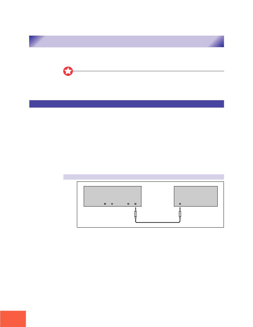
Connecting the Analog Outputs
The A3000 comes standard with the following stereo output jacks.
STEREO OUT |
Main analog output. |
ASSIGNABLE OUT |
You can set the jacks to operate independently of the STEREO |
|
OUT jacks, so that they output selected samples or programs |
|
only. The feature is useful, for example, when you want to send |
|
the main signal to one audio device while sending a specific |
|
sample to a different device. But it is also possible to set these |
|
jacks so that they output the same signal as the STEREO OUT |
|
jacks. ( 299) |
If you have installed the optional I/O expansion board (AIEB1 board), your A3000 will include three additional ASSIGNABLE OUT pairs (ASSIGNABLE OUT jacks 1 to 6).
For monaural output:
A3000 Rear Panel |
|
|
Amp, mixer, etc. |
ASSIGNABLE OUT |
STEREO OUT |
|
|
R |
L |
R L/MONO |
INPUT |
Chapter 1 Setting Up
22
Connecting the A3000 Outputs
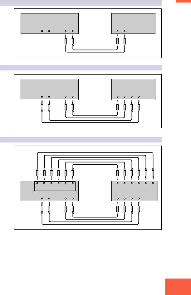
For stereo output: |
|
|
|
|
1 |
|
|
|
|
|
|
A3000 Rear Panel |
|
|
Amp, mixer, etc. |
Chapter |
|
|
|
|
|||
ASSIGNABLE OUT |
STEREO OUT |
INPUT |
|
||
R |
L |
R L/MONO |
L |
R |
|
For assignable output:
A3000 Rear Panel |
|
|
Amp, mixer, etc. |
|
||
ASSIGNABLE OUT |
STEREO OUT |
INPUT 1 |
INPUT 2 |
|||
R |
L |
R L/MONO |
L |
R |
L |
R |
Assignable output using AIEB1 expansion board:
A3000 |
5 |
4 |
3 |
2 |
1 |
L |
R |
L |
R |
L |
R |
6 |
|||||||||||
Rear Panel |
|
ASSIGNABLE OUT |
|
INPUT 3 |
INPUT 4 |
INPUT 5 |
|||||
|
|
|
|
|
|
Amp, mixer, etc. |
|
|
|
|
|
ASSIGNABLE OUT |
|
STEREO OUT |
INPUT 1 |
INPUT 2 |
|
|
|||||
|
R |
L |
|
R |
L/MONO |
L |
R |
L |
R |
|
|
(It is not necessary, of course, to connect up all of the outputs on the expansion board. Connect only the outputs you need to use.)
Chapter 1 Setting Up
23
Connecting the A3000 Outputs
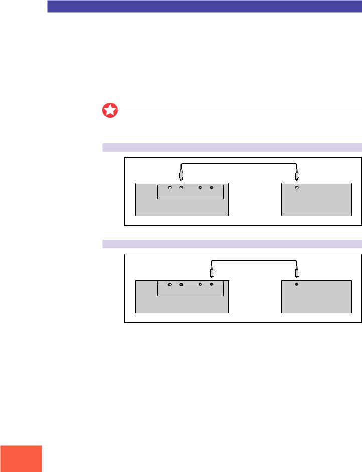
Connecting the Digital Outputs
You can add digital I/O capacity to the A3000 by installing the optional I/O expansion board (AIEB1 board). The board enables direct digital output of A3000 playback and digital through-put.
For purposes of compatibility, the AIEB1 board includes two different output types: OPTICAL OUT (optical fiber) and DIGITAL OUT (coaxial cable). Note that both of these outputs always produce identical signals.
The digital outputs function as assignable outputs. You can set them to output selected samples or programs, or you can set them to produce the same output as the STEREO OUT jacks (by setting the To AsgnOut parameter to DIG&OPT; 299).
Important
The OPTICAL connectors are protected by plastic covers. You must remove the cover before connecting the cable. Please remember to replace the cover when you disconnect the cable.
OPTICAL output connection
IN |
OUT |
IN |
OUT |
OPTICAL INPUT |
|
OPTICAL |
DIGITAL |
||||
|
|||||
A3000 Rear Panel |
|
|
|
Digital device |
|
Coaxial output connection
IN |
OUT |
IN |
OUT |
DIGITAL INPUT |
|
OPTICAL |
DIGITAL |
||||
|
|||||
A3000 Rear Panel |
|
|
|
Digital device |
|
Chapter 1 Setting Up
24
Connecting the Audio Inputs
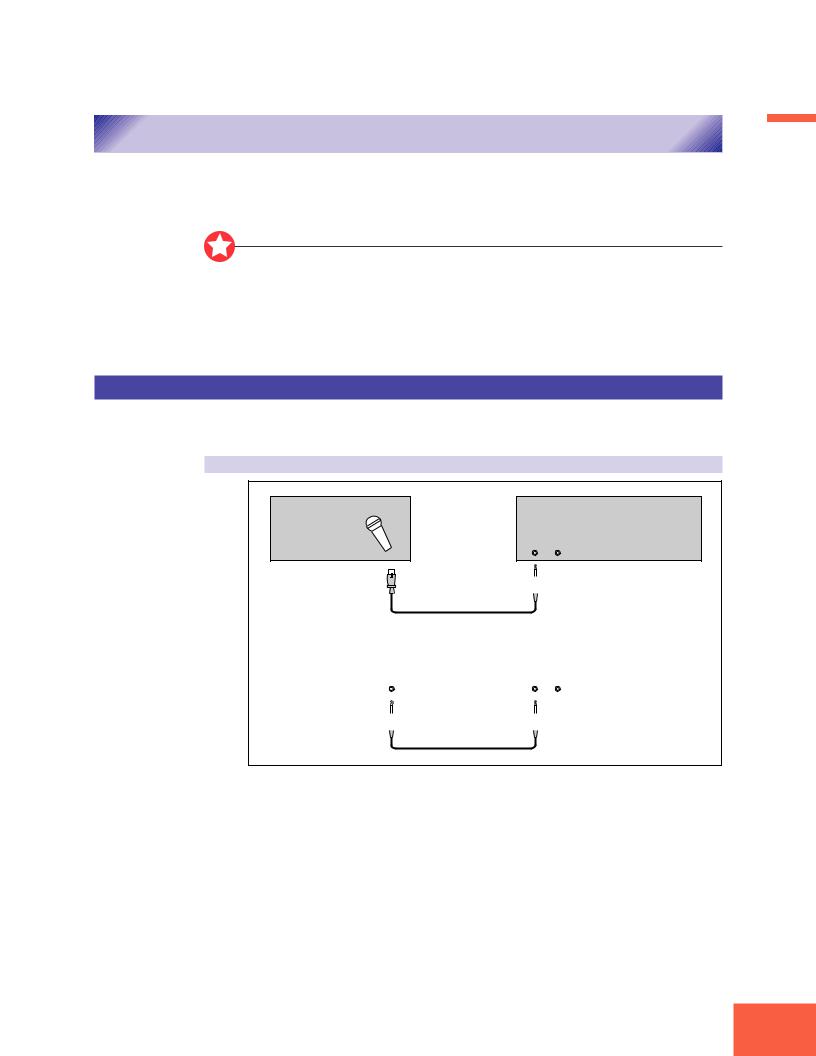
Connecting the Audio Inputs
This section explains how to connect the A3000 to a microphone, cassette recorder, or other sound source.
Chapter 1
Important
•Be sure that power to the A3000 and to peripheral devices is OFF before making these connections. Connecting devices while power is ON may result in damage to amps or speakers.
•Digital I/O connections are available only if the optional AIEB1 board is installed.
•To select the input to be used for recording, use the Input parameter on the RecData page ( 227).
Connecting to Analog Input
The following illustrations show how to connect to an analog input source, such as a microphone, analog tape recorder, or analog synthesizer.
For monaural input
Microphone, etc. |
A3000 Front Panel |
INPUT
L R
|
|
|
|
|
|
|
|
|
|
|
|
|
|
Tape recorder, synth, etc. |
|
A3000 Front Panel |
||||
|
|
|
|
|
INPUT |
|
OUTPUT |
|
|
L |
R |
||
|
|
|
|
|
|
|
|
|
|
|
|
|
|
|
|
|
|
|
|
|
Chapter 1 Setting Up
25

Connecting the Audio Inputs
For stereo input
Microphone, etc. |
A3000 Front Panel |
INPUT
L R
|
|
|
|
|
|
|
|
|
|
|
|
|
|
|
|
|
|
|
|
|
|
Tape recorder, synth, etc. |
|
|
|
A3000 Front Panel |
||||||
|
OUTPUT |
|
|
|
INPUT |
|||||
|
L |
R |
|
|
|
L |
R |
|||
|
|
|
|
|
|
|
|
|
|
|
|
|
|
|
|
|
|
|
|
|
|
|
|
|
|
|
|
|
|
|
|
|
Connecting to Digital Input
Installation of the optional I/O expansion board (AIEB1 board) lets you record digital signals directly from a digital input source — such as a CD player or DAT recorder.
For purposes of compatibility, the AIEB1 board includes two different input types: OPTICAL (optical fiber) and DIGITAL (coaxial cable).
OPTICAL input connection
|
OPTICAL OUTPUT |
IN |
OUT |
IN |
OUT |
|
OPTICAL |
DIGITAL |
|||
|
|
||||
Digital device |
|
A3000 Rear Panel |
|
|
|
Coaxial input connection
|
DIGITAL OUTPUT |
IN |
OUT |
IN |
OUT |
|
OPTICAL |
DIGITAL |
|||
|
|
||||
Digital device |
|
A3000 Rear Panel |
|
|
|
Chapter 1 Setting Up
26

MIDI Connections
This section explains how to connect the A3000 to MIDI devices.
MIDI Connections
Chapter 1
Important
Be sure that power to the A3000 and to peripheral devices is OFF before making MIDI connections. Connecting devices while power is ON may result in MIDI processing errors or unexpected and continuous sound output.
About MIDI
The following overview introduces some basic MIDI concepts. Readers familiar with MIDI may wish to skip to “MIDI Connection Configurations,” on the next page.
What is MIDI?
MIDI (for “Musical Instrument Digital Interface”) is a standard, internationally-recog- nized interface for music-related digital communication among electronic instruments, computers, sequencers, and related devices.
MIDI connectors and cables
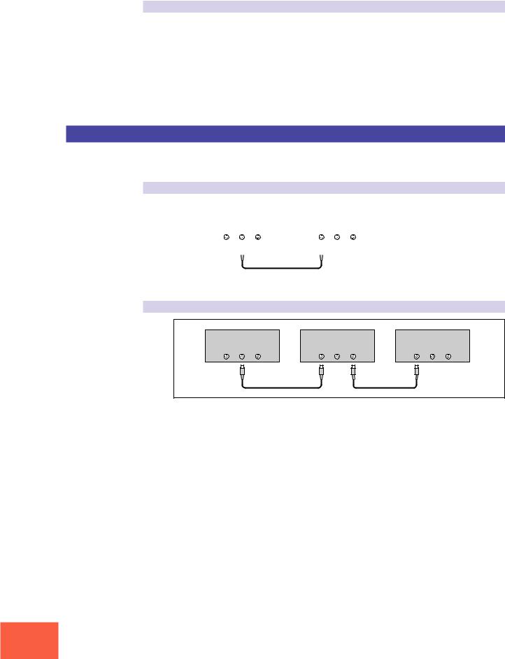
MIDI devices provide MIDI connectors marked IN, OUT, and THRU. The IN connector receives data from external devices, the OUT connector outputs locally produced data, and the THRU connector relays data received at the IN connector. MIDI connections are made by running standard MIDI cables between connectors on different devices. Each MIDI cable connects the OUT or THRU connector of one device to the IN connector of another device.
Channels
A single MIDI cable carries up to 16 channels of performance data. If you have a MIDI setup consisting of three keyboards outputting performance data to a fourth device, for example, each keyboard would be transmitting data over a different channel. Each channel is identified by its channel number (1 to 16).
Chapter 1 Setting Up
27
MIDI Connections
Data types
Each channel can carry a variety of data types. Data types include the following.
Note data: |
Keys (on keyboard), and key striking force |
Control change: |
Controller movement (modulation wheel, foot controller, etc.) |
Program change: |
Change in voice or program |
Aftertouch: |
Pressure applied to key after initial strike |
Pitchbend: |
Movement of the pitchbend wheel |
Bulk data: |
Voice and device settings and related data |
MIDI Connection Configurations
You can use MIDI connections to control the A3000 from an external keyboard, sequencer, or computer, or to transfer A3000 data to an external MIDI device.
Connecting to keyboard or MIDI controller:
|
|
|
|
|
|
|
|
|
|
Keyboard (or controller) |
|
A3000 Rear Panel |
|
||||
|
MIDI |
|
|
|
MIDI |
|
|
|
|
IN OUT |
THRU |
|
IN OUT |
THRU |
|
||
|
|
|
|
|
|
|
|
|
|
|
|
|
|
|
|
|
|
|
|
|
|
|
|
|
|
|
|
|
|
|
|
|
|
|
|
Connecting to keyboard/controller and external tone generator:
Keyboard (or controller) |
A3000 Rear Panel |
Tone generator (synthesizer, etc.) |
||||||
|
MIDI |
|
|
MIDI |
|
|
MIDI |
|
IN |
OUT |
THRU |
IN |
OUT |
THRU |
IN |
OUT |
THRU |
Chapter 1 Setting Up
28
 Loading...