


GG
IIntegratedAmplifier
AmplificateurIIntégré
OOWNER’SMANUAL
MODED’EMPLOI BEDIENUNGSANLEITUNG BRUKSANVISNING MANUALEDIISTRUZIONI MANUALDEINSTRUCCIONES GEBRUIKSAANWIJZING
ИНСТРУКЦИЯ ПО ЭКСПЛУАТАЦИИ
|
|
© 2013 Yamaha Corporation |
Printed in Malaysia ZH10680 |

CAUTION: READ THIS BEFORE OPERATING YOUR UNIT.
1To assure the finest performance, please read this manual carefully. Keep it in a safe place for future reference.
2Install this sound system in a well ventilated, cool, dry, clean place - away from direct sunlight, heat sources, vibration, dust, moisture, and/or cold. For proper ventilation, allow the following minimum clearances around this unit.
Top: 30 cm Rear: 20 cm Sides: 20 cm
3Locate this unit away from other electrical appliances, motors, or transformers to avoid humming sounds.
4Do not expose this unit to sudden temperature changes from cold to hot, and do not locate this unit in an environment with high humidity (i.e. a room with a humidifier) to prevent condensation inside this unit, which may cause an electrical shock, fire, damage to this unit, and/or personal injury.
5Avoid installing this unit where foreign object may fall onto this unit and/or this unit may be exposed to liquid dripping or splashing. On the top of this unit, do not place:
–Other components, as they may cause damage and/or discoloration on the surface of this unit.
–Burning objects (i.e. candles), as they may cause fire, damage to this unit, and/or personal injury.
–Containers with liquid in them, as they may fall and liquid may cause electrical shock to the user and/or damage to this unit.
6Do not cover this unit with a newspaper, tablecloth, curtain, etc. in order not to obstruct heat radiation. If the temperature inside this unit rises, it may cause fire, damage to this unit, and/or personal injury.
7Do not plug in this unit to an AC wall outlet until all connections are complete.
8Do not operate this unit upside-down. It may overheat, possibly causing damage.
9Do not use force on switches, knobs and/or cords.
10When disconnecting the power cable from the AC wall outlet, grasp the plug; do not pull the cable.
11Do not clean this unit with chemical solvents; this might damage the finish. Use a clean, dry cloth.
12Only voltage specified on this unit must be used. Using this unit with a higher voltage than specified is dangerous and may cause fire, damage to this unit, and/or personal injury. Yamaha will not be held responsible for any damage resulting from use of this unit with a voltage other than specified.
13To prevent damage by lightning, keep the power cable and outdoor antennas disconnected from an AC wall outlet or this unit during a lightning storm.
14Do not attempt to modify or fix this unit. Contact qualified Yamaha service personnel when any service is needed. The cabinet should never be opened for any reasons.
15When not planning to use this unit for long periods of time (i.e. vacation), disconnect the AC power plug from the AC wall outlet.
16Be sure to read the “TROUBLESHOOTING” section on common operating errors before concluding that this unit is faulty.
17Before moving this unit, press A (power) to set this unit to standby mode, and then disconnect the AC power plug from the AC wall outlet.
18Condensation will form when the surrounding temperature changes suddenly. Disconnect the power cable from the outlet, then leave this unit alone.
19When using this unit for a long time, this unit may become warm. Turn the power off, then leave this unit alone for cooling.
20Install this unit near the AC wall outlet and where the AC power plug can be reached easily.
21The batteries shall not be exposed to excessive heat such as sunshine, fire or the like.
22Excessive sound pressure from earphones and headphones can cause hearing loss.
This unit is not disconnected from the AC power source as long as it is connected to the AC wall outlet, even if this unit itself is turned off by A. This state is called the standby mode. In this state, this unit is designed to consume a very small quantity of power.
WARNING
TO REDUCE THE RISK OF FIRE OR ELECTRIC SHOCK, DO NOT EXPOSE THIS UNIT TO RAIN OR MOISTURE.
This label is required to be attached to a product of which the temperature of the top cover may be hot during operation.
■ For U.K. customers
If the socket outlets in the home are not suitable for the plug supplied with this appliance, it should be cut off and an appropriate 3 pin plug fitted. For details, refer to the instructions described below.
Note
The plug severed from the mains lead must be destroyed, as a plug with bared flexible cord is hazardous if engaged in a live socket outlet.
■ Special Instructions for U.K. Model
IMPORTANT
THE WIRES IN MAINS LEAD ARE COLOURED IN ACCORDANCE WITH THE FOLLOWING CODE: Blue: NEUTRAL
Brown: LIVE
As the colours of the wires in the mains lead of this apparatus may not correspond with the coloured markings identifying the terminals in your plug, proceed as follows:
The wire which is coloured BLUE must be connected to the terminal which is marked with the letter N or coloured BLACK. The wire which is coloured BROWN must be connected to the terminal which is marked with the letter L or coloured RED. Make sure that neither core is connected to the earth terminal of the three pin plug.
i En
CONTENTS
INTRODUCTION |
|
USEFUL FEATURES ............................................ |
1 |
SUPPLIED ACCESSORIES ................................. |
1 |
CONTROLS AND FUNCTIONS ......................... |
2 |
Front panel................................................................. |
2 |
Rear panel .................................................................. |
4 |
Remote control........................................................... |
5 |
Using the remote control ........................................... |
7 |
PREPARATION |
|
CONNECTIONS .................................................... |
8 |
Connecting speakers and source components............ |
8 |
Connecting power cable ............................................ |
9 |
BASIC OPERATION |
|
PLAYBACK .......................................................... |
10 |
Playing a source....................................................... |
10 |
Enjoying pure, high fidelity sound (Pure Direct) .... |
11 |
Using the sleep timer ............................................... |
11 |
ADVANCED OPERATION |
|
SETTING THE OPTION MENU FOR EACH |
|
INPUT SOURCE............................................... |
12 |
Option menu items................................................... |
12 |
ADDITIONAL INFORMATION |
|
TROUBLESHOOTING ....................................... |
13 |
SPECIFICATIONS............................................... |
15 |
■ About this manual
•yindicates a tip for your operation.
•The instructions in this manual describe the operation of this unit with the supplied remote control. You can also use the buttons or knobs on the front panel if they have the same or similar names as those on the remote control.
USEFUL FEATURES
This unit allows you to: |
|
Enjoy pure, high fidelity sound by using the Pure |
Save power by using the AUTO POWER STANDBY |
Direct function (see page 11) |
function (see page 12) |
Use the remote control of this unit to operate a Yamaha tuner and/or CD player (see page 6)
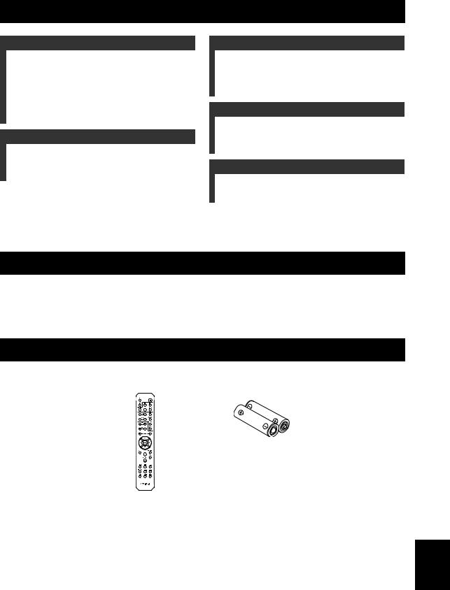
SUPPLIED ACCESSORIES
Please check that you received all of the following parts.
Remote control |
Batteries (x2) |
|
(AA, R6, UM-3) |
INTRODUCTION |
|
|
|
|
|
PREPARATION |
|
|
|
|
|
OPERATION |
BASIC |
|
|
|
|
OPERATION |
ADVANCED |
|
|
|
|
INFORMATION |
ADDITIONAL |
|
|
English
1 En

INTRODUCTION
CONTROLS AND FUNCTIONS
Front panel
1 A(power)
Turns this unit on, or sets it to standby mode.
Note
This unit consumes a small amount of power even when in standby mode.
2Remote control sensor
Receives infrared signals from the remote control.
3STANDBY/ON indicator
Indicator |
Status |
|
|
Brightly lit |
The power of this unit is “on”. |
|
|
Dimly lit |
This unit is in “standby” mode. |
|
|
Off |
The power of this unit is “off”. |
|
To turn off this unit, disconnect |
|
the power cable from an AC |
|
wall outlet. |
|
|
4 SP (SPEAKERS) A/B indicators
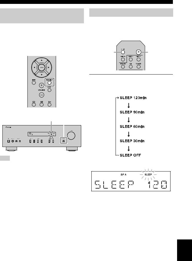
5SLEEP indicator
Lights up when the sleep timer is turned on (see page 11).
6Multi-information display
Shows information when adjusting or changing settings.
7PURE DIRECT indicator
Lights up when the Pure Direct function is on.
8Front panel display
Shows information about the operational status of this unit.
9PURE DIRECT button
Reproduces any input source in the purest sound possible. (see page 11).
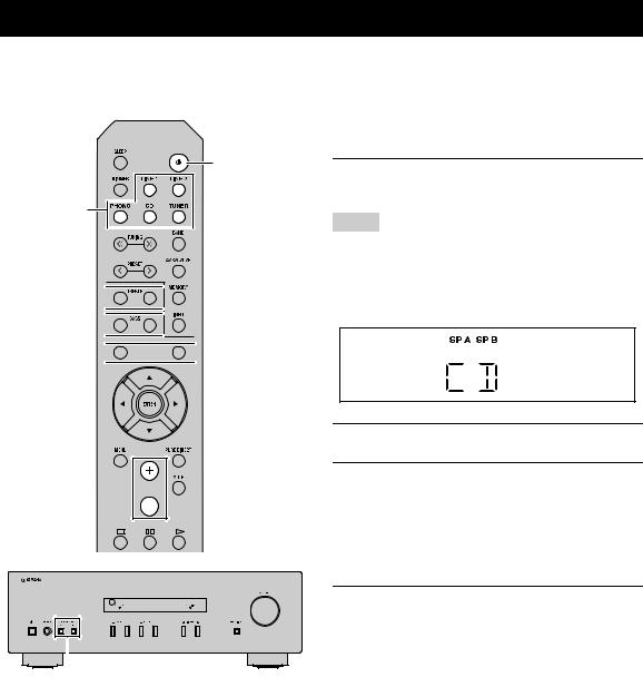
Light up according to the set of speakers selected. Both indicators light up when both sets of speakers are selected.
2 En
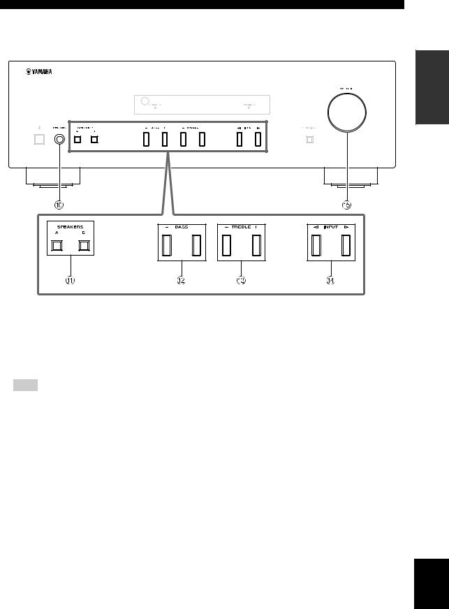
0PHONES jack
Outputs audio to your headphones for private listening.
Note
Press SPEAKERS A/B so that the SP A/B indicators (see page 2) turn off before you connect your headphones to the PHONES jack.
ASPEAKERS A/B
Turns on or off the speaker set connected to the SPEAKERS A and/or SPEAKERS B terminals on the rear panel each time the corresponding button is pressed (see page 10).
BBASS –/+
Increases or decreases the low frequency response. Control range: –10 dB to +10 dB
CONTROLS AND FUNCTIONS
INTRODUCTION
CTREBLE –/+
Increases or decreases the high frequency response. Control range: –10 dB to +10 dB
DINPUT l / h
Selects the input source you want to listen to.
EVOLUME control
Increases or decreases the sound output level.
English
3 En

CONTROLS AND FUNCTIONS
Rear panel
1Power cable
For connecting this unit to an AC wall outlet (see page 9).
2GND terminal
Used to connect a turntable (see page 8).
3PHONO jacks
Used to connect a turntable (see page 8).
4CD jacks
Used to connect a CD player (see page 8).
5TUNER jacks
Used to connect a tuner (see page 8).
6LINE 1 jacks
Used to connect audio components (see page 8).
7LINE 2 jacks
PB (Playback) jacks
Used to connect to audio output jacks of an audio component.
REC (Recording) jacks
Used to connect to audio input jacks of an audio component.
8SPEAKERS terminals
Used to connect speakers (see page 8).
9VOLTAGE SELECTOR (Only for General model)
4 En

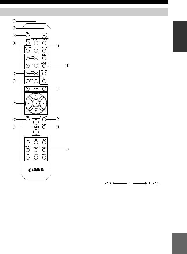
Remote control
■ Common controls
The following parts and controls can be used no matter which input source is selected.
1Infrared signal transmitter
Sends infrared signals.
2A(power)
Turns this unit on, or sets it to standby mode.
3SLEEP
Sets the sleep timer (see page 11).
CONTROLS AND FUNCTIONS
4DIMMER
Select the brightness level of the front panel display from 3 levels by pressing this button repeatedly.
y
•This setting is retained even if you turn off this unit.
•The default setting is the brightest.
5TREBLE –/+
Increases or decreases the high frequency response. Control range: –10 dB to +10 dB
6BASS –/+
Increases or decreases the low frequency response. Control range: –10 dB to +10 dB
7B / C / D / E / ENTER
Selects and confirms items in the Option menu (see page 12).
8MENU
Turns the Option menu on and off (see page 12).
9VOLUME +/–
Increases or decreases the sound output level.
0Input selector buttons
Select the input source you want to listen to.
y
The input source names correspond to the names of the connection jacks on the rear panel.
ABALANCE L/R
Adjusts the sound output balance of the left and right speakers to compensate for sound imbalances. Control range:
(+20 dB) |
(center) |
(+20 dB) |
The opposite side of |
|
The opposite side of |
channel is muted. |
|
channel is muted. |
BPURE DIRECT button
Reproduces any input source in the purest sound possible (see page 11).
CMUTE
Mutes the sound output. Press again to restore the sound output to the previous volume level.
Continued to the next page. 
INTRODUCTION
English
5 En

CONTROLS AND FUNCTIONS
■ Yamaha tuner control buttons
The following buttons can be used to control various functions of a Yamaha tuner.
DTUNING jj / ii
Selects the tuning frequency.
A/B/C/D/E, PRESET j / i
Selects a preset FM/AM station.
A/B/C/D/E: Selects the preset group from A to E. PRESET j / i: Selects the preset number.
BAND
Selects the reception band (FM/AM).
MEMORY
Stores the current FM/AM station as a preset.
INFO
Only for Europe model:
Switches information shown on the front panel display.
Note
Even when using a Yamaha tuner, certain components and features may not be available. Refer to your component’s owner’s manual for more information.
■ Yamaha CD player controls
The following buttons can be used to control a Yamaha CD player.
E Yamaha CD player control buttons
s |
Stops playback |
e |
Pauses playback |
p |
Starts playback |
DISC SKIP |
Skips to the next disc in a CD changer |
b |
Skips backward |
a |
Skips forward |
|
Ejects the disc |
w |
Rewinds playback |
f |
Fast-forwards playback |
Note
Even when using a Yamaha CD player, certain components and features may not be available. Refer to your component’s owner’s manual for more information.
6 En
CONTROLS AND FUNCTIONS
Using the remote control
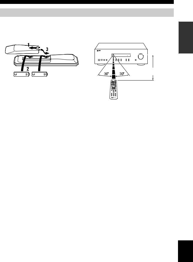
■ Installing batteries |
■ Operation range |
||||
|
|
|
Point the remote control at the remote control sensor on |
||
|
|
|
this unit and remain within the operating range shown |
||
|
|
|
below. |
||
|
|
|
|
|
|
|
|
|
|
|
|
|
|
|
|
|
|
Approximately 6 m 
AA, R6, UM-3 batteries
Remote control
INTRODUCTION
■Notes on remote control and batteries
•The area between the remote control and this unit must be clear of large obstacles.
•Be careful not to spill water or other liquids on the remote control.
•Be careful not to drop the remote control.
•Do not leave or store the remote control in the following conditions:
–places of high humidity, such as near a bathroom
–places of high temperatures, such as near a heater or stove
–places of extremely low temperatures
–dusty places
•Change all batteries if you notice the operation range of the remote control narrows.
•If the batteries run out, immediately remove them from the remote control to prevent an explosion or acid leak.
•If you find leaking batteries, discard the batteries immediately, taking care not to touch the leaked material. If the leaked material comes into contact with your skin or gets into your eyes or mouth, rinse it away immediately and consult a doctor. Clean the battery compartment thoroughly before installing new batteries.
•Do not use old batteries together with new ones. This may shorten the life of the new batteries or cause old batteries to leak.
•Do not use different types of batteries (such as alkaline and manganese batteries) together. Batteries that look the same may have a different specification.
•Before inserting new batteries, wipe the battery compartment clean.
•Dispose of batteries according to your regional regulations.
•Keep the batteries in a location out of reach of children.
Batteries can be dangerous if a child were to put in his or her mouth.
•If you plan not to use this unit for a long period of time, remove the batteries from this unit. Otherwise, the batteries will wear out, possibly resulting in a leakage of battery liquid that may damage this unit.
English
7 En

PREPARATION
CONNECTIONS
Connecting speakers and source components
Make sure to connect L (left) to L, R (right) to R, “+” to “+” and “–” to “–”. If the connections are faulty, no sound will be heard from the speakers, and if the polarity of the speaker connections is incorrect, the sound will be unnatural and lack bass. Refer to the owner’s manual for each of your components.
Make sure to use RCA cables to connect audio components.
CAUTION
•Do not connect this unit or other components to the main power until all connections between components are complete.
•Do not let bare speaker wires touch each other or any metal part of this unit. This could damage this unit and/or the speakers.
Speakers A
Right Left
CD player |
DVD player, etc. |
Audio |
Audio |
out |
out |
GND |
Audio |
Audio |
Audio |
Audio |
|
out |
out |
out |
in |
Tuner CD recorder, Right Left
etc. |
Speakers B |
|
Turntable
y
•The PHONO jacks are designed for connecting a turntable with an MM cartridge.
•Connect your turntable to the GND terminal to reduce noise in the signal. However, for some turntables, you may hear less noise without the GND connection.
8 En
■ REC jacks
•The REC jacks output audio signals of the currently selected input (except when LINE 2 is selected).
•Volume level, tone control, balance and Pure Direct settings do not affect the REC jacks.
■ Connecting speaker cables
1Remove approximately 10 mm of insulation from the end of each speaker cable.
2Twist the bare wires of the cable firmly together.
3Unscrew the knob.
4Insert one bare wire into the hole in the side of each terminal.
5Tighten the knob to secure the wire.
Red: positive (+)
Black: negative (–)
■Connecting via banana plug (Except for Asia, U.K. and Europe
models)
1Tighten the knob.
2Insert the banana plug into the end of the corresponding terminal.
Banana plug
CAUTION
Speaker impedance must be set as shown below.
Speaker connection |
Speaker impedance |
|
|
SPEAKERS A or |
8 Ω or higher |
SPEAKERS B |
|
|
|
SPEAKERS A and |
16 Ω or higher |
SPEAKERS B |
(except for North |
|
America model) |
|
|
Bi-wiring |
8 Ω or higher |
|
|
CONNECTIONS
■ Bi-wire connection
Bi-wire connection separates the woofer from the combined midrange and tweeter section.
A bi-wire compatible speaker has four binding post terminals. These two sets of terminals allow the speaker to be split into two independent sections. With these connections, the mid and high frequency drivers are connected to one set of terminals and the low frequency driver to another set of terminals.
Rear panel
Speaker
PREPARATION
Connect the other speaker to the other set of terminals in the same way.
Note
When making bi-wire connections, remove the shorting bridges or cables on the speaker.
y
To use the bi-wire connections, press SPEAKERS A and SPEAKERS B on the front panel so that both SP A and B light up on the front panel display.
Connecting power cable
Plug the power cable into an AC wall outlet after all other connections are complete.
CAUTION
Only for General model:
Before connecting the power cable, make sure you set VOLTAGE SELECTOR of this unit according to your local voltage. Improper setting of VOLTAGE SELECTOR may cause fire and damage to this unit.
To the AC wall outlet with the power cable
English
9 En
BASIC OPERATION
PLAYBACK
Playing a source |
|
|
|
|
1 |
Press A (power) to turn on this unit. |
|
|
|
|
|
|
|
2 |
Press one of the Input selector buttons to |
|
|
|
select the desired input source. |
A (power) |
Input selector |
buttons |
TREBLE –/+ 


BASS –/+ 


BALANCE L/R 


3Press SPEAKERS A and/or SPEAKERS B on the front panel to select desired speaker(s).
Notes
•When one set of speakers is connected using bi-wire connections, or when using two sets of speakers simultaneously (A and B), make sure SP A and SP B are displayed on the front panel display.
•When listening with headphones, turn off the speakers.
VOLUME +/– 


SPEAKERS A/B
4Play the source.
5Press VOLUME +/– to adjust the sound output level.
y
You can adjust the tonal quality by using BASS –/+, TREBLE –/+, and the left/right sound balance of speakers by using BALANCE L/R (see page 5).
6When finished listening, press A (power) to set this unit to standby mode.
Press A(power) to turn this unit on again.
y
•You can also use the buttons or knobs on the front panel if they have the same or similar names as those on the remote control.
•For recording, see page 4.
10 En
Enjoying pure, high fidelity sound (Pure Direct)
The Pure Direct function bypasses unnecessary circuitry in this unit to reduce electrical noise when playing the selected source. This allows you to enjoy high fidelity sound quality.
The PURE DIRECT indicator lights up and the front panel display turns off after a few seconds.
PURE DIRECT button
PURE DIRECT indicator
PLAYBACK
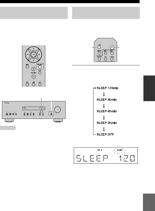
Using the sleep timer
Use this feature to automatically set this unit to standby mode after a certain amount of time. The sleep timer is useful when you are going to sleep while this unit is playing or recording a source.
SLEEP |
A (power) |
Press SLEEP repeatedly to set the amount of time before this unit is set to standby mode.
Each time you press SLEEP, the front panel display changes cyclically as shown below.
OPERATION |
BASIC |
|
|
Note
The BASS, TREBLE, and BALANCE controls do not function while the PURE DIRECT feature is turned on.
The SLEEP indicator blinks while setting the amount of time for the sleep timer.
If the sleep timer is set, the SLEEP indicator on the front panel display lights up.
y
To cancel the sleep timer, do one of the following:
–Select “SLEEP OFF”.
–Set this unit to standby mode.
English
11 En

ADVANCED OPERATION
SETTING THE OPTION MENU FOR EACH INPUT SOURCE
The Option menu allows you to configure various settings for each input source and recall those settings automatically when an input source is selected.
1 Press one of the Input selector buttons to select the desired input source.
2 Press MENU.
Input selector
buttons
3 Press B / C to select the desired menu item, and then press ENTER.
B/ C/ D
ENTER
4Press B / C to change the settings. y
•For certain menu items, you must press ENTER to save the new setting.
•To return to the screen where you can select menu items, press D.
5To exit the Option menu, press MENU.
MENU 
Option menu items
Menu item |
Description |
|
|
MAX VOL |
Sets the maximum volume level so that the volume will not be accidentally increased above a |
|
certain level. |
|
Adjustable range: 01 to 99, MAX* |
|
|
INITIAL VOLUME (INIT VOL) |
Sets the volume at the time this unit is turned on. When this parameter is set to “OFF”, the |
|
volume level used when this unit was set to standby is applied. |
|
Adjustable range: OFF*, MUTE, 01 to 99, MAX |
|
|
AUTO POWER STANDBY |
Sets this unit to standby mode automatically if no operation is performed in the specified time. |
(AUTO STBY) |
Choices: OFF/2H/4H/8H*/12H |
|
|
y
The default settings are marked with “*”.
12 En

ADDITIONAL INFORMATION
TROUBLESHOOTING
Refer to the chart below if this unit does not function properly. If the problem you are experiencing is not listed below or if the instructions below do not help, set this unit to standby mode, disconnect the power cable, and then contact the nearest authorized Yamaha dealer or service center.
■ General
Problem |
Cause |
Remedy |
See |
|
|
page |
|
|
|||
|
|
|
|
|
|
|
|
|
|
|
|
This unit fails to turn |
The power cable is not connected or the |
Connect the power cable firmly. |
— |
|
|
on. |
plug is not completely inserted. |
|
|
|
|
|
|
|
|
||
|
|
|
|
|
|
|
The impedance setting of the connected |
Use speaker(s) with proper speaker impedance. |
9 |
|
|
|
speaker is too small. |
|
|
|
|
|
|
|
|
|
|
|
|
|
|
|
|
|
The protection circuitry has been activated |
Check that the speaker wires are not touching each |
8 |
|
|
|
because of a short circuit, etc. |
other and then turn the power of this unit back on. |
|
|
|
|
|
|
|
||
|
|
|
|
|
|
|
This unit has been exposed to a strong |
Set this unit to standby mode, disconnect the power |
— |
|
|
|
external electric shock (such as lightning |
cable, plug it back in after 30 seconds, then use it |
|
|
|
|
or strong static electricity). |
normally. |
|
|
|
|
|
|
|
|
|
No sound |
Incorrect input or output cable |
Connect the cables properly. If the problem persists, |
8 |
|
|
|
connections. |
the cables may be defective. |
|
|
|
|
|
|
|
||
|
|
|
|
|
|
|
No appropriate input source has been |
Select an appropriate input source by pressing one of |
10 |
|
|
|
selected. |
the Input selector buttons on the remote control |
|
|
|
|
|
(INPUT l/ hon the front panel). |
|
|
|
|
|
|
|
|
|
|
The SPEAKERS A/B switches are not set |
Turn on the corresponding SPEAKERS A or |
10 |
|
|
|
properly. |
SPEAKERS B. |
|
|
|
|
|
|
|
||
|
|
|
|
|
|
|
Speaker connections are not secure. |
Secure the connections. |
8 |
|
|
|
|
|
|
|
|
|
Output has been muted. |
Deactivate the mute function. |
5 |
|
|
|
|
|
|
|
|
|
The MAX VOL or INITIAL VOLUME |
Set the setting to a higher value. |
12 |
|
|
|
setting is set too low. |
|
|
|
|
|
|
|
|
|
|
|
|
|
|
|
|
|
The component corresponding to the |
Turn the component on and make sure it is playing. |
— |
|
|
|
selected input source is turned off or is not |
|
|
|
|
|
playing. |
|
|
|
|
|
|
|
|
ADDITIONAL INFORMATION |
|
|
|
|
|
|
|
The sound suddenly |
The protection circuitry has been activated |
Check that the speaker wires are not touching each |
8 |
|
|
|
|
||||
goes off. |
because of a short circuit, etc. |
other and then turn the power of this unit back on. |
|
|
|
|
|
|
|||
|
|
|
|
|
|
|
This unit has become too hot. |
Make sure the openings on the top panel are not |
— |
|
|
|
|
blocked. |
|
|
|
|
|
|
|
|
|
|
|
|
|
|
|
|
The AUTO POWER STANDBY or |
Change the AUTO POWER STANDBY setting to a |
12 |
|
|
|
SLEEP function has set this unit to |
longer setting or OFF from the Option menu by |
|
|
|
|
standby mode. |
pressing MENU. |
|
|
|
|
|
|
|
|
|
Only the speaker on |
Incorrect cable connections. |
Connect the cables properly. If the problem persists, |
8 |
|
|
one side can be |
|
the cables may be defective. |
|
|
|
|
|
|
|
||
heard. |
|
|
|
|
|
Incorrect setting for the BALANCE L/R |
Set the BALANCE L/R setting to the appropriate |
5 |
|
|
|
|
|
|
|||
|
setting. |
position. |
|
|
|
|
|
|
|
||
|
|
|
|
|
|
There is a lack of bass |
The + and – wires are connected in |
Connect the speaker wires to the correct + and – |
8 |
|
|
and no ambience. |
reverse at the amplifier or the speakers. |
phase. |
|
|
|
|
|
|
|||
|
|
|
|
|
|
A “humming” sound |
Incorrect cable connections. |
Connect the audio plugs firmly. If the problem |
8 |
|
|
can be heard. |
|
persists, the cables may be defective. |
|
|
|
|
|
|
|
||
|
|
|
|
|
|
|
No connection from the turntable to the |
Make the GND connection between the turntable and |
8 |
|
English |
|
GND terminal. |
this unit. |
|
||
|
|
|
|||
|
|
|
|
||
|
|
|
|
|
|
|
|
|
|
|
|
13 En

TROUBLESHOOTING
Problem |
Cause |
Remedy |
See |
|
page |
||||
|
|
|
||
|
|
|
|
|
The volume level |
The component connected to the LINE 2 |
Turn on the power of the component. |
|
|
cannot be increased, |
PB/REC jacks of this unit is turned off. |
|
— |
|
or the sound is |
|
|
||
|
|
|
||
distorted. |
|
|
|
|
|
|
|
|
|
The sound is |
This unit has been set to standby mode. |
Turn on the power of this unit. |
|
|
degraded when |
|
|
|
|
listening with |
|
|
10 |
|
headphones |
|
|
||
connected to a CD |
|
|
|
|
player connected to |
|
|
|
|
this unit. |
|
|
|
|
|
|
|
|
|
The BASS, TREBLE |
The PURE DIRECT function is turned on. |
The PURE DIRECT function must be turned off to |
|
|
and BALANCE |
|
apply these settings to the sound. |
11 |
|
settings do not |
|
|
||
|
|
|
||
applied to the sound. |
|
|
|
|
|
|
|
|
|
The remote control |
Wrong distance or angle. |
The remote control will function within a maximum |
7 |
|
does not work nor |
|
range of 6 m and no more than 30 degrees off-axis |
||
function properly. |
|
from the front panel. |
|
|
|
|
|
|
|
|
Direct sunlight or lighting (from an |
Reposition this unit. |
|
|
|
inverter type of fluorescent lamp, etc.) is |
|
— |
|
|
striking the remote control sensor of this |
|
||
|
|
|
||
|
unit. |
|
|
|
|
|
|
|
|
|
The batteries are weak. |
Replace all batteries. |
7 |
|
|
|
|
|
|
Your tuner and/or CD |
The remote control does not support the |
Refer to the owner’s manual supplied with the tuner |
|
|
player cannot be |
tuner and/or CD player. |
and/or CD palyer. |
— |
|
operated with the |
|
|
||
|
|
|
||
remote control. |
|
|
|
|
|
|
|
|
|
“OVER HEAT” |
This unit has become too hot. |
Make sure the openings on the top panel are not |
— |
|
appears on the front |
|
blocked. |
||
panel display. |
|
|
|
|
|
|
|
|
|
“CHECK SP” appears |
Speaker cables got shorted out. |
Twist bare wires of speaker cables firmly, and then |
— |
|
on the front panel |
|
connect to this unit and speakers properly. |
||
display. |
|
|
|
|
|
|
|
|
14 En
SPECIFICATIONS
AUDIO SECTION
• Minimum RMS output power
(8 Ω, 40 Hz to 20 kHz, 0.2% THD)
[General, Korea, Australia, U.K. and Europe models]
........................................................................... |
100 W + 100 W |
[China and Asia models] ...................................... |
85 W + 85 W |
• Input sensitivity/Input impedance (1 kHz, 100 W/8 Ω) |
|
PHONO (MM) ..................................................... |
10.0 mV/47 kΩ |
CD, etc. ................................................................. |
500 mV/47 kΩ |
• Output level/Output impedance |
|
CD, etc. (Input 1 kHz, 500 mV) |
500 mV/2.2 kΩ |
REC .................................................................. |
|
CD, etc. (Input 1 kHz, 500 mV, 8 Ω) |
470 mV/470 Ω |
PHONES ............................................................ |
|
• Frequency response |
|
CD, etc. (20 Hz to 20 kHz) ........................................... |
0 ± 0.5 dB |
CD, etc. (10 Hz to 100 kHz) ......................................... |
0 ± 3.0 dB |
• RIAA equalization deviation |
|
PHONO (MM) ................................................................. |
± 0.5 dB |
• Total harmonic distortion |
|
PHONO (MM) to REC (20 Hz to 20 kHz, 2 V) .... |
0.025% or less |
CD, etc. to SPEAKERS |
|
(20 Hz to 20 kHz, 50 W, 8 Ω) .................................... |
0.2% or less |
• Signal to noise ratio (IHF-A network) |
|
PHONO (MM) (10 mV input shorted) .................. |
75 dB or more |
CD, etc. (500 mV input shorted) ......................... |
100 dB or more |
• Residual noise (IHF-A network) ............................................ |
70 µV |
• Tone control characteristics |
|
BASS |
|
Boost/Cut (50 Hz) ......................................................... |
± 10 dB |
TREBLE |
|
Boost/Cut (20 kHz) ....................................................... |
± 10 dB |
GENERAL
• Power supply |
|
[General model] ...................... |
AC 110-120/220-240 V, 50/60 Hz |
[China model]....................................................... |
AC 220 V, 50Hz |
[Korea model] ....................................................... |
AC 220 V, 60Hz |
[Australia model] ............................................... |
AC 240 V, 50 Hz |
[U.K. and Europe models] ................................. |
AC 230 V, 50 Hz |
[Asia model] .......................................... |
AC 220-240 V, 50/60 Hz |
• Power consumption
[General, Korea, Australia, U.K. and Europe models]
.......................................................................................... |
175 W |
[China and Asia models] .................................................... |
140 W |
• Standby power consumption |
|
[China, Korea, Australia, U.K., Europe and Asia models] |
|
................................................................................ |
0.5 W or less |
• Dimensions (W × H × D) ................................ |
435 × 141 × 333 mm |
• Weight .................................................................................... |
6.7 kg |
* Specifications are subject to change without notice.
Information for Users on Collection and Disposal of Old Equipment and Used Batteries
These symbols on the products, packaging, and/or accompanying documents mean that used electrical and electronic products and batteries should not be mixed with general household waste.
For proper treatment, recovery and recycling of old products and used batteries, please take them to applicable collection points, in accordance with your national legislation and the Directives 2002/96/EC and 2006/66/EC.
By disposing of these products and batteries correctly, you will help to save valuable resources and prevent any potential negative effects on human health and the environment which could otherwise arise from inappropriate waste handling.
For more information about collection and recycling of old products and batteries, please contact your local municipality, your waste disposal service or the point of sale where you purchased the items.
[Information on Disposal in other Countries outside the European Union]
These symbols are only valid in the European Union. If you wish to discard these items, please contact your local authorities or dealer and ask for the correct method of disposal.
Note for the battery symbol (bottom two symbol examples):
This symbol might be used in combination with a chemical symbol. In this case it complies with the requirement set by the Directive for the chemical involved.
INFORMATION |
ADDITIONAL |
|
|
English
15 En

ATTENTION : VEUILLEZ LIRE CE QUI SUIT AVANT D’UTILISER
L’APPAREIL.
1Pour utiliser l’appareil au mieux de ses possibilités, lisez attentivement ce mode d’emploi. Conservez-le soigneusement pour référence.
2Installez cet ensemble audio dans un endroit bien aéré, frais, sec et propre - veillez à ce qu’il soit à l’abri de la lumière directe du soleil, des sources de chaleur, des vibrations, des poussières, de l’humidité et/ou du froid. Pour une ventilation correcte, ménagez l’espace minimum suivant autour de cet appareil.
Au-dessus : 30 cm
À l’arrière : 20 cm Sur les côtés : 20 cm
3Placez l’appareil loin des équipements, moteurs et transformateurs électriques, pour éviter les ronflements parasites.
4N’exposez pas l’appareil à des variations brutales de température, ne le placez pas dans un environnement très humide (par exemple dans une pièce contenant un humidificateur) car cela peut entraîner la condensation d’humidité à l’intérieur de l’appareil qui elle-même peut être responsable de décharge électrique, d’incendie, de dommage à l’appareil ou de blessure corporelle.
5Evitez d’installer l’appareil dans un endroit où des objets peuvent tomber, ainsi que là où l’appareil pourrait être exposé à des éclaboussures ou des gouttes d’eau. Sur le dessus de l’appareil, ne placez pas :
–d’autres appareils qui peuvent endommager la surface de l’appareil ou provoquer sa décoloration.
–des objets se consumant (par exemple, une bougie) qui peuvent être responsables d’incendie, de dommage à l’appareil ou de blessure corporelle.
–des récipients contenant des liquides qui peuvent être à l’origine de décharge électrique ou de dommage à l’appareil.
6Ne couvrez pas l’appareil d’un journal, d’une nappe, d’un rideau, etc. car cela empêcherait l’évacuation de la chaleur. Toute augmentation de la température intérieure de l’appareil peut être responsable d’incendie, de dommage à l’appareil ou de blessure corporelle.
7Ne branchez pas la fiche du câble d’alimentation de l’appareil sur une prise secteur aussi longtemps que tous les raccordements n’ont pas été effectués.
8Ne pas faire fonctionner l’appareil à l’envers. Il risquerait de chauffer et d’être endommagé.
9N’exercez aucune force excessive sur les commutateurs, les boutons et les cordons.
10Pour débrancher la fiche du câble d’alimentation au niveau de la prise secteur, saisissez la fiche et ne tirez pas sur le cordon.
11Ne nettoyez pas l’appareil au moyen d’un solvant chimique, ce qui pourrait endommager la finition. Utilisez un chiffon sec et propre.
12N’alimentez l’appareil qu’à partir de la tension prescrite. Alimenter l’appareil sous une tension plus élevée est dangereux et peut être responsable d’incendie, de dommage à l’appareil ou de blessure corporelle. Yamaha ne saurait être tenue responsable des dommages résultant de l’alimentation de l’appareil sous une tension autre que celle prescrite.
13Pour empêcher tout dommage causé par les éclairs, déconnectez le câble d’alimentation et toute antenne extérieure de la prise murale pendant un orage.
14Ne tentez pas de modifier ni de réparer l’appareil. Consultez le service Yamaha compétent pour toute réparation qui serait requise. Le coffret de l’appareil ne doit jamais être ouvert, quelle que soit la raison.
15Si vous envisagez de ne pas vous servir de l’appareil pendant une longue période (par exemple, pendant les vacances), débranchez la fiche du câble d’alimentation au niveau de la prise secteur.
16Lisez la section intitulée « GUIDE DE DÉPANNAGE » où figurent une liste d’erreurs de manipulation communes avant de conclure que l’appareil présente une anomalie de fonctionnement.
17Avant de déplacer l’appareil, appuyez sur
A(alimentation) pour mettre l’appareil en mode veille, puis débranchez la fiche du cordon d’alimentation au niveau de la prise secteur.
18La condensation se forme lorsque la température ambiante change brusquement. En ce cas, débranchez la fiche du câble d’alimentation et laissez l’appareil reposer.
19La température de l’appareil peut augmenter en raison d’une utilisation prolongée. En ce cas, coupez l’alimentation de l’appareil et laissez-le au repos pour qu’il refroidisse.
20Installez cet appareil à proximité de la prise secteur et à un emplacement où la fiche du câble d’alimentation est facilement accessible.
21Les piles ne doivent pas être exposées à une chaleur extrême, par exemple au soleil, à une flamme, etc.
22Une pression excessive du son par les écouteurs et le casque d’écoute peut entraîner la perte de l’ouïe.
Cet appareil n’est pas déconnecté du secteur tant qu’il reste branché à la prise de courant, même si l’appareil en soi est éteint par la touche A. Il se trouve alors « en veille ». En mode veille, l’appareil consomme une très faible quantité de courant.
AVERTISSEMENT
POUR RÉDUIRE LES RISQUES D’INCENDIE OU DE DÉCHARGE ÉLECTRIQUE, N’EXPOSEZ PAS CET APPAREIL À LA PLUIE OU À L’HUMIDITÉ.
Cette étiquette doit être apposée sur un produit dont le capot supérieur peut devenir chaud lorsqu’il fonctionne.
i Fr

TABLE DES MATIÈRES
INTRODUCTION |
|
FONCTIONS UTILES........................................... |
1 |
ACCESSOIRES FOURNIS................................... |
1 |
COMMANDES ET FONCTIONS........................ |
2 |
Panneau avant ............................................................ |
2 |
Panneau arrière .......................................................... |
4 |
Télécommande........................................................... |
5 |
Utilisation de la télécommande ................................. |
7 |
PRÉPARATION |
|
RACCORDEMENTS............................................. |
8 |
Raccordement des enceintes et des |
|
composants source................................................. |
8 |
Raccordement du cordon d’alimentation................... |
9 |
OPÉRATIONS DE BASE |
|
LECTURE ............................................................. |
10 |
Lecture d’une source................................................ |
10 |
Écoutez un son pur de haute fidélité |
|
(Pure Direct) ........................................................ |
11 |
Utilisation de la minuterie de veille......................... |
11 |
OPÉRATIONS AVANCÉES |
|
PARAMÉTRAGE DU MENU OPTION POUR |
|
CHAQUE SOURCE D’ENTRÉE.................... |
12 |
Éléments du menu Option ....................................... |
12 |
INFORMATIONS COMPLÉMENTAIRES |
|
GUIDE DE DÉPANNAGE................................... |
13 |
CARACTÉRISTIQUES TECHNIQUES............ |
15 |
■ À propos de ce manuel
•Le symbole yattire votre attention sur un conseil d’utilisation.
•Les instructions de ce mode d’emploi décrivent les opérations de cet appareil à l’aide de la télécommande fournie avec l’appareil. Vous pouvez également utiliser les touches ou les boutons du panneau avant s’ils portent le même nom ou un nom semblable sur la télécommande.
FONCTIONS UTILES
Cet appareil permet d’effectuer les opérations suivantes : |
|
Écouter un son pur de haute fidélité à l’aide de la |
Économiser de l’énergie grâce à la fonction AUTO |
fonction Pure Direct (voir page 11) |
POWER STANDBY (voir page 12) |
Utiliser la télécommande de cet appareil pour |
|
commander un syntoniseur et/ou un lecteur de CD |
|
Yamaha (voir page 6) |
|
ACCESSOIRES FOURNIS
Vérifiez que vous avez reçu tous les articles suivants.
Télécommande |
Piles (× 2) |
|
(AA, R6, UM-3) |
INTRODUCTION |
|
|
|
|
|
PRÉPARATION |
|
|
|
|
|
BASE |
OPÉRATIONS |
|
DE |
|
|
AVANCÉES |
OPÉRATIONS |
|
|
|
|
COMPLÉMENTAIRES |
INFORMATIONS |
|
|
Français
1 Fr

INTRODUCTION
COMMANDES ET FONCTIONS
Panneau avant
1 A(alimentation)
Met l’appareil sous tension ou en mode veille.
Remarque
Cet appareil consomme une faible quantité de courant même lorsqu’il est en mode veille.
2Capteur de télécommande
Reçoit les signaux infrarouges émis par la télécommande.
3Témoin STANDBY/ON
Témoin |
État |
|
|
Fortement |
L’alimentation de cet appareil |
éclairé |
est « sous tension ». |
|
|
Faiblement |
Cet appareil est en mode |
éclairé |
« veille ». |
|
|
Éteint |
L’alimentation de cet appareil |
|
est « hors tension ». |
|
Pour éteindre l’appareil, |
|
débranchez le cordon |
|
d’alimentation de la prise |
|
secteur. |
|
|
4Témoins SP (SPEAKERS) A/B
S’allument en fonction du jeu d’enceintes sélectionné. Les deux témoins s’allument lorsque les deux jeux d’enceintes sont sélectionnés.
5Témoin SLEEP
S’allume lorsque la minuterie de veille est activée (voir page 11).
6Affichage multi-informations
Affiche des informations lors du réglage ou de la modification de certains paramètres.
7Témoin PURE DIRECT
S’allume lorsque la fonction Pure Direct est activée.
8Afficheur du panneau avant
Indique des informations sur l’état opérationnel de l’appareil.
9Touche PURE DIRECT
Pour reproduire toute source d’entrée avec le son le plus pur possible (voir page 11).
2 Fr
COMMANDES ET FONCTIONS
0Prise PHONES
Dévie le son vers votre casque en vue d’une écoute individuelle.
Remarque
Appuyez sur SPEAKERS A/B afin d’éteindre les témoins SP A/B (voir page 2) avant de brancher votre casque sur la prise PHONES.
ASPEAKERS A/B
Active ou désactive le jeu d’enceintes raccordées aux bornes SPEAKERS A et/ou SPEAKERS B situées sur le panneau arrière à chaque pression sur la touche correspondante (voir page 10).
BBASS –/+
Augmente ou réduit la réponse dans les basses fréquences.
Plage de commande : –10 dB à +10 dB
INTRODUCTION
CTREBLE –/+
Augmente ou réduit la réponse dans les hautes fréquences.
Plage de commande : –10 dB à +10 dB
DINPUT l / h
Sélectionne la source d’entrée que vous souhaitez écouter.
ECommande VOLUME
Augmente ou réduit le niveau sonore.
Français
3 Fr

COMMANDES ET FONCTIONS
Panneau arrière
1Cordon d’alimentation
Utilisé pour brancher cet appareil à une prise secteur (voir page 9).
2Borne GND
Utilisée pour brancher un tourne-disque (voir page 8).
3Prises PHONO
Utilisée pour brancher un tourne-disque (voir page 8).
4Prises CD
Utilisées pour brancher un lecteur de CD (voir page 8).
5Prises TUNER
Utilisées pour brancher un syntoniseur (voir page 8).
6Prises LINE 1
Utilisées pour brancher des composants audio (voir page 8).
7Prises LINE 2
Prises PB (Lecture)
Utilisées pour brancher les prises de sortie audio d’un composant audio.
Prises REC (Enregistrement)
Utilisées pour brancher les prises d’entrée audio d’un composant audio.
8Bornes SPEAKERS
Utilisées pour brancher des enceintes (voir page 8).
9VOLTAGE SELECTOR (Seulement pour le modèle général)
4 Fr
Télécommande
■ Commandes communes
Il est possible d’utiliser les touches et les commandes suivantes quelle que soit la source d’entrée sélectionnée.
1Émetteur de signal infrarouge
Envoie des signaux infrarouges.
2A(alimentation)
Met l’appareil sous tension ou en mode veille.
3SLEEP
Règle la minuterie de veille (voir page 11).
COMMANDES ET FONCTIONS
4DIMMER
Choisissez le niveau d’éclairage sur l’afficheur du panneau avant parmi 3 niveaux en appuyant sur cette touche de façon répétée.
y
•Ce réglage est conservé même si vous mettez cet appareil hors tension.
•Le réglage par défaut est le niveau le plus lumineux.
5TREBLE –/+
Augmente ou réduit la réponse dans les hautes fréquences.
Plage de commande : –10 dB à +10 dB
6BASS –/+
Augmente ou réduit la réponse dans les basses fréquences.
Plage de commande : –10 dB à +10 dB
7B / C / D / E / ENTER
Sélectionne et confirme les articles du menu Option (voir page 12).
8MENU
Ouvre et ferme le menu Option (voir page 12).
9VOLUME +/–
Augmente ou réduit le niveau sonore.
0Touches du sélecteur d’entrée
Pour sélectionner la source d’entrée que vous souhaitez écouter.
y
Les noms des sources d’entrée correspondent à ceux des prises de raccordement du panneau arrière.
ABALANCE L/R
Équilibre le son reproduit par les enceintes gauche et droite afin de compenser le déséquilibre sonore. Plage de commande :
(+20 dB) |
(centre) |
(+20 dB) |
Le côté opposé du |
|
Le côté opposé du |
canal est désactivé. |
|
canal est désactivé. |
BTouche PURE DIRECT
Pour reproduire toute source d’entrée avec le son le plus pur possible (voir page 11).
CMUTE
Désactive le son. Appuyez de nouveau sur cette touche pour rétablir le niveau sonore antérieur.
Suite page suivante. 
INTRODUCTION
Français
5 Fr

COMMANDES ET FONCTIONS
■ Touches de commande d’un syntoniseur
Yamaha
Vous pouvez utiliser les touches suivantes pour commander les différentes fonctions d’un syntoniseur Yamaha.
DTUNING jj / ii
Sélectionne la fréquence de syntonisation.
A/B/C/D/E, PRESET j / i
Sélectionne une station FM/AM présélectionnée. A/B/C/D/E : Sélectionne le groupe de présélections de A à E.
PRESET j/ i: Sélectionne le numéro de présélection.
BAND
Sélectionne la bande de réception (FM/AM).
MEMORY
Mémorise la station FM/AM actuelle sous la forme d’une présélection.
INFO
Seulement pour le modèle pour l’Europe : Permet de changer les informations indiquées sur l’afficheur du panneau avant.
Remarque
Même si vous utilisez un syntoniseur Yamaha, il se peut que certains composants et fonctions ne soient pas disponibles. Reportez-vous au mode d’emploi des composants pour plus d’informations.
■ Commandes d’un lecteur de CD Yamaha
Vous pouvez utiliser les touches suivantes pour commander un lecteur de CD Yamaha.
ETouches de commande d’un lecteur de CD Yamaha
s |
Arrête la lecture |
e |
Suspend la lecture |
p |
Démarre la lecture |
DISC SKIP |
Passe au disque suivant dans un |
|
chargeur multidisque |
b |
Recule |
a |
Avance |
|
Éjecte le disque |
w |
Rembobine |
f |
Lecture en avance rapide |
Remarque
Même si vous utilisez un lecteur de CD Yamaha, il se peut que certains composants et certaines fonctions ne soient pas disponibles. Reportez-vous au mode d’emploi des composants pour plus d’informations.
6 Fr
|
|
|
|
COMMANDES ET FONCTIONS |
|
|
|
|
|
|
|
Utilisation de la télécommande |
|
|
|
||
■ Installation des piles |
■ Portée de la télécommande |
||||
|
|
|
Dirigez la télécommande vers le capteur de télécommande |
||
|
|
|
de cet appareil et restez dans zone de portée de la |
||
|
|
|
télécommande indiquée ci-dessous. |
||
|
|
|
|
|
|
|
|
|
|
|
|
|
|
|
|
|
|
Environ 6 m
Piles AA, R6, UM-3
Télécommande
INTRODUCTION
■Remarques sur la télécommande et les piles
•Entre la télécommande et l’appareil, l’espace doit être libre de tout obstacle encombrant.
•Faites attention à ne pas renverser d’eau ou d’autres liquides sur la télécommande.
•Faites attention à ne pas laisser tomber la télécommande.
•Ne conservez pas ou ne rangez pas la télécommande dans les endroits suivants :
–lieux très humides, par exemple près d’une salle de bains,
–lieux très chauds, par exemple près d’un appareil de chauffage ou d’un poêle,
–lieux exposés à des températures très basses,
–endroits poussiéreux.
•Remplacez toutes les piles lorsque vous remarquez que la portée de la télécommande est plus courte.
•Retirez immédiatement les piles épuisées de la télécommande pour éviter tout risque d’explosion ou de fuite d’acide.
•Si les piles fuient, mettez-les au rebut immédiatement, en évitant de toucher le produit qui a fui. En cas de contact entre le produit qui a fui et votre peau, vos yeux ou votre bouche, rincez-les immédiatement et consultez un médecin. Avant d’installer de nouvelles piles, nettoyez soigneusement le logement des piles.
•Ne combinez jamais des piles neuves et des piles usagées. Cela peut réduire la durée de vie des piles neuves ou faire fuir les anciennes.
•N’utilisez pas non plus des piles de types différents (par exemple, des piles alcalines et des piles au manganèse). Des piles d’apparence identique peuvent présenter des caractéristiques différentes.
•Avant d’insérer des piles neuves, nettoyez leur logement.
•Les piles doivent être mises au rebut conformément à la réglementation locale.
•Conservez les piles dans un endroit hors de portée des enfants.
Les piles peuvent être dangereuses si un enfant les met dans sa bouche.
•Si vous prévoyez de ne pas utiliser cet appareil pendant un certain temps, retirez les piles. Sinon, les piles s’usent et risquent de fuir, ce qui peut endommager l’appareil.
Français
7 Fr

PRÉPARATION
RACCORDEMENTS
Raccordement des enceintes et des composants source
Assurez-vous de raccorder L (gauche) sur L, R (droite) sur R, « + » sur « + » et « – » sur « – ». Si le raccordement est défectueux, aucun son n’est émis par l’enceinte, et si la polarité de la connexion est incorrecte, les sons manquent de naturel et de composantes graves. Reportez-vous au mode d’emploi de chaque composant.
Assurez-vous d’utiliser les câbles RCA pour brancher les composants audio.
ATTENTION
•Ne raccordez pas cet appareil ou d’autres composants au secteur tant que toutes les connexions entre les composants ne sont pas établies.
•Ne laissez pas les fils d’enceinte dénudés se toucher ni entrer en contact avec les pièces métalliques de cet appareil. Cela risquerait d’endommager l’appareil et/ou les enceintes.
Enceintes A
Droite Gauche
Lecteur de CD |
Lecteur de DVD, |
etc. |
|
Sortie |
Sortie |
audio |
audio |
GND |
Sortie |
Sortie |
Sortie |
Entrée |
|
audio |
audio |
audio |
audio |
Syntoniseur Enregistreur de CD, Droite Gauche
etc. |
Enceintes B |
|
Tourne-disque
y
•Les prises PHONO sont destinées au raccordement d’un tourne-disque doté d’une cartouche MM.
•Raccordez votre tourne-disque à la borne GND afin de réduire le bruit dans le signal. Toutefois, il se peut que vous entendiez moins de bruit en débranchant certains tourne-disques de la borne GND.
8 Fr

■ Prises REC
•Les prises REC sortent des signaux audio de l’entrée actuellement sélectionnée (sauf lorsque LINE 2 est sélectionné).
•Les réglages du niveau de volume, du contrôle du son, de l’équilibre et de Pure Direct n’affectent pas les prises REC.
■ Raccordement des câbles d’enceinte
1Retirez environ 10 mm d’isolation à l’extrémité de chaque câble d’enceinte.
2Torsadez fermement les fils dénudés du câble.
3Dévissez le bouton.
4Insérez un fil dénudé dans l’orifice situé sur le côté de chaque borne.
5Serrez le bouton pour fixer le fil.
Rouge : positif (+)
Noir : négatif (–)
■Raccordement avec une fiche banane (Sauf modèles pour l’Asie, le Royaume-
Uni et l’Europe)
1Vissez le bouton.
2Insérez la fiche banane dans l’extrémité de la borne correspondante.
Fiche banane
ATTENTION
L’impédance de l’enceinte doit être réglée comme indiqué ci-dessous.
Raccordement des |
Impédances des |
enceintes |
enceintes |
SPEAKERS A ou |
8 Ω ou supérieur |
SPEAKERS B |
|
|
|
SPEAKERS A et |
16 Ω ou supérieur |
SPEAKERS B |
(sauf pour le modèle pour |
|
l’Amérique du Nord) |
|
|
Bifilaire |
8 Ω ou supérieur |
RACCORDEMENTS
■ Connexion bifilaire
Une connexion bifilaire a pour effet de séparer les graves des médiums et des aigus.
Une enceinte compatible avec ce type de connexion est pourvue de quatre bornes de connexion. Ces deux jeux de bornes permettent de diviser l’enceinte en deux sections indépendantes. Lorsque ces connexions sont effectuées, les circuits d’attaque des médiums et des aigus sont reliés à un jeu de bornes et le circuit d’attaque des graves est relié à l’autre jeu de bornes.
Panneau arrière
Enceinte
PRÉPARATION
Raccordez l’autre enceinte à l’autre jeu de bornes en procédant de la même manière.
Remarque
Lorsque vous établissez des connexions bifilaires, retirez les ponts de court-circuitage ou les câbles des enceintes.
y
Pour utiliser les connexions bifilaires, appuyez sur SPEAKERS A et SPEAKERS B sur le panneau avant pour que SP A et B s’allument sur l’afficheur du panneau avant.
Raccordement du cordon d’alimentation
Une fois tous les raccordements effectués, branchez le cordon d’alimentation sur une prise secteur.
ATTENTION
Seulement pour le modèle général :
Avant de brancher le cordon d’alimentation, assurez-vous d’avoir réglé le VOLTAGE SELECTOR de cet appareil en fonction de votre tension locale. Un réglage incorrect du VOLTAGE SELECTOR peut provoquer un incendie et endommager l’appareil.
Vers la prise secteur avec le cordon d’alimentation
Français
9 Fr

OPÉRATIONS DE BASE
LECTURE
Lecture d’une source
 A (alimentation)
Touches du sélecteur d’entrée
TREBLE –/+ 


BASS –/+ 


BALANCE L/R 


VOLUME +/– 


SPEAKERS A/B
1Appuyez sur A (alimentation) pour allumer l’appareil.
2Appuyez sur l’une des touches du sélecteur d’entrée pour sélectionner la source d’entrée voulue.
3Appuyez sur SPEAKERS A et/ou sur SPEAKERS B sur le panneau avant pour sélectionner la ou les enceintes voulues.
Remarques
•Lorsqu’un jeu d’enceintes est branché à l’aide de connexions bifilaires, ou lorsque deux jeux d’enceintes sont utilisés simultanément (A et B), vérifiez que SP A et SP B sont affichés sur l’afficheur du panneau avant.
•Si vous écoutez à l’aide d’un casque, désactivez les enceintes.
4Lisez la source.
5Appuyez sur VOLUME +/– pour régler le niveau sonore.
y
Vous pouvez régler la qualité des tonalités à l’aide de BASS –/+, TREBLE –/+, et l’équilibre gauche/droite du son des enceintes à l’aide de BALANCE L/R (voir page 5).
6Une fois l’écoute terminée, appuyez sur A
(alimentation) pour mettre l’appareil en mode veille.
Appuyez sur A(alimentation) pour remettre l’appareil sous tension.
y
•Vous pouvez également utiliser les touches ou les boutons du panneau avant s’ils portent le même nom ou un nom semblable sur la télécommande.
•Pour l’enregistrement, voir page 4.
10 Fr
Écoutez un son pur de haute fidélité (Pure Direct)
La fonction Pure Direct contourne les circuits inutiles de cet appareil afin de réduire le bruit électronique pendant la lecture de la source sélectionnée. Cela vous permet d’écouter une qualité de son haute fidélité.
Le témoin PURE DIRECT s’allume et l’afficheur du panneau avant s’éteint après quelques secondes.
Touche PURE
DIRECT
Témoin PURE DIRECT
Remarque
Les commandes BASS, TREBLE et BALANCE ne fonctionnent pas lorsque la fonction PURE DIRECT est activée.
LECTURE
Utilisation de la minuterie de veille
Cette fonction permet de mettre automatiquement l’appareil en mode veille après un certain laps de temps. La minuterie de veille est utile lorsque vous allez vous coucher alors que l’appareil lit ou enregistre une source.
SLEEP |
A (alimentation) |
Appuyez plusieurs fois de suite sur SLEEP pour régler le laps de temps avant la mise en mode veille de l’appareil.
Chaque fois que vous appuyez sur SLEEP, l’afficheur du panneau avant change comme indiqué ci-dessous.
Le témoin SLEEP clignote pendant le réglage de la durée de la minuterie de veille.
Lorsque la minuterie de veille est activée, le témoin SLEEP sur l’afficheur du panneau avant s’allume.
y
Pour annuler la minuterie de veille, exécutez l’une des actions suivantes :
–Sélectionnez « SLEEP OFF ».
–Mettez cet appareil en mode veille.
DE OPÉRATIONS BASE
Français
11 Fr
OPÉRATIONS AVANCÉES
PARAMÉTRAGE DU MENU OPTION POUR CHAQUE SOURCE
D’ENTRÉE
Le menu Option vous permet de configurer divers paramètres pour chaque source d’entrée et de rappeler automatiquement ces paramètres lorsqu’une source d’entrée est sélectionnée.
1 Appuyez sur l’une des touches du sélecteur d’entrée pour sélectionner la source d’entrée voulue.
Touches du
sélecteur 


 2 Appuyez sur MENU. d’entrée
B/ C/ D
ENTER
MENU 
3Appuyez sur B / C pour sélectionner l’élément de menu souhaité, puis appuyez sur ENTER.
4Appuyez sur B / C pour modifier les paramètres.
y
•Pour certains éléments de menu, vous devez appuyer sur ENTER pour enregistrer le nouveau réglage.
•Pour revenir à l’écran où vous pouvez sélectionner les éléments de menu, appuyez sur D.
5Pour quitter le menu Option, appuyez sur MENU.
Éléments du menu Option
Élément de menu |
Description |
|
|
MAX VOL |
Règle le niveau sonore maximal afin que le volume ne puisse pas être accidentellement |
|
augmenté au-dessus d’un certain niveau. |
|
Plage ajustable : 01 à 99, MAX* |
|
|
INITIAL VOLUME (INIT VOL) |
Règle le volume au moment de la mise sous tension de l’appareil. Lorsque ce paramètre est |
|
réglé sur « OFF », le niveau sonore utilisé lors de la mise en veille de l’appareil est appliqué. |
|
Plage ajustable : OFF*, MUTE, 01 à 99, MAX |
|
|
AUTO POWER STANDBY |
Règle l’appareil automatiquement en mode veille s’il reste inactif pendant la durée spécifiée. |
(AUTO STBY) |
Choix : OFF/2H/4H/8H*/12H |
|
|
y
Les paramètres par défaut sont indiqués par un « * ».
12 Fr
 Loading...