


UBL
Integrated Amplifier
Amplificateur Intégré
OWNER’S MANUAL
MODE D’EMPLOI
MANUAL DE INSTRUCCIONES
IMPORTANT SAFETY INSTRUCTIONS
CAUTION |
RISK OF ELECTRIC SHOCK |
DO NOT OPEN |
CAUTION: TO REDUCE THE RISK OF |
ELECTRIC SHOCK, DO NOT REMOVE |
COVER (OR BACK). NO USER-SERVICEABLE |
PARTS INSIDE. REFER SERVICING TO |
QUALIFIED SERVICE PERSONNEL. |
• Explanation of Graphical Symbols
The lightning flash with arrowhead symbol, within an equilateral triangle, is intended to alert you to the presence of uninsulated “dangerous voltage” within the product’s enclosure that may be of sufficient magnitude to constitute a risk of electric shock to persons.
The exclamation point within an equilateral triangle is intended to alert you to the presence of important operating and maintenance (servicing) instructions in the literature accompanying the appliance.
IMPORTANT
Please record the serial number of this unit in the space below.
MODEL:
Serial No.:
The serial number is located on the rear of the unit. Retain this Owner’s Manual in a safe place for future reference.
1Read these instructions.
2Keep these instructions.
3Heed all warnings.
4Follow all instructions.
5Do not use this apparatus near water.
6Clean only with dry cloth.
7Do not block any ventilation openings. Install in accordance with the manufacturer’s instructions.
8Do not install near any heat sources such as radiators, heat registers, stoves, or other apparatus (including amplifiers) that produce heat.
9Do not defeat the safety purpose of the polarized or grounding-type plug. A polarized plug has two blades with one wider than the other. A grounding type plug has two blades and a third grounding prong. The wide blade or the third prong are provided for your safety. If the provided plug does not fit into your outlet, consult an electrician for replacement of the obsolete outlet.
10Protect the power cord from being walked on or pinched particularly at plugs, convenience receptacles, and the point where they exit from the apparatus.
11Only use attachments/accessories specified by the manufacturer.
12Use only with the cart, stand, tripod, bracket, or table specified by the
manufacturer, or sold with the apparatus. When a cart is used, use caution when moving the cart/apparatus combination to avoid injury from tip-over.
13Unplug this apparatus during lightning storms or when unused for long periods of time.
14Refer all servicing to qualified service personnel. Servicing is required when the apparatus has been damaged in any way, such as power-supply cord or plug is damaged, liquid has been spilled or objects have fallen into the apparatus, the apparatus has been exposed to rain or moisture, does not operate normally, or has been dropped.
We Want You Listening For A Lifetime
Yamaha and the Electronic Industries Association’s Consumer Electronics Group want you to get the most out of your equipment by playing it at a safe level. One that lets the sound come through loud and clear without annoying blaring or distortion – and, most importantly, without affecting your sensitive hearing. Since hearing damage from loud sounds is often undetectable until it is too late, Yamaha and the Electronic Industries Association’s Consumer Electronics Group recommend you to avoid prolonged exposure from excessive volume levels.
i En

|
|
IMPORTANT SAFETY INSTRUCTIONS |
|
|
|
|
|
|
FCC INFORMATION (for US customers) |
||
|
|
|
|
|
1 IMPORTANT NOTICE: DO NOT MODIFY THIS |
Compliance with FCC regulations does not guarantee |
|
|
UNIT! |
that interference will not occur in all installations. If |
|
|
This product, when installed as indicated in the |
this product is found to be the source of interference, |
|
|
instructions contained in this manual, meets FCC |
which can be determined by turning the unit “OFF” |
|
|
requirements. Modifications not expressly approved by |
and “ON”, please try to eliminate the problem by using |
|
|
Yamaha may void your authority, granted by the FCC, |
one of the following measures: |
|
|
to use the product. |
Relocate either this product or the device that is being |
|
|
2 IMPORTANT: When connecting this product to |
||
|
affected by the interference. |
||
|
accessories and/or another product use only high quality |
||
|
Utilize power outlets that are on different branch |
||
|
shielded cables. Cable/s supplied with this product MUST |
||
|
be used. Follow all installation instructions. Failure to |
(circuit breaker or fuse) circuits or install AC line |
|
|
follow instructions could void your FCC authorization to |
filter/s. |
|
|
use this product in the USA. |
In the case of radio or TV interference, relocate/ |
|
|
3 NOTE: This product has been tested and found to comply |
reorient the antenna. If the antenna lead-in is 300 ohm |
|
|
ribbon lead, change the lead-in to coaxial type cable. |
||
|
with the requirements listed in FCC Regulations, Part 15 |
||
|
|
|
|
|
for Class “B” digital devices. Compliance with these |
If these corrective measures do not produce |
|
|
requirements provides a reasonable level of assurance that |
satisfactory results, please contact the local retailer |
|
|
your use of this product in a residential environment will |
authorized to distribute this type of product. If you can |
|
|
not result in harmful interference with other electronic |
not locate the appropriate retailer, please contact |
|
|
devices. |
Yamaha Corporation of America A/V Division, 6600 |
|
|
This equipment generates/uses radio frequencies and, |
Orangethorpe Avenue, Buena Park, CA 90620, USA. |
|
|
if not installed and used according to the instructions |
The above statements apply ONLY to those products |
|
found in the users manual, may cause interference |
distributed by Yamaha Corporation of America or its |
|
harmful to the operation of other electronic devices. |
||
subsidiaries. |
||
|
FOR CANADIAN CUSTOMERS
To prevent electric shock, match wide blade of plug to wide slot and fully insert.
CAN ICES-3 (B)/NMB-3(B)
COMPLIANCE INFORMATION STATEMENT
(DECLARATION OF CONFORMITY PROCEDURE)
Responsible Party: |
Yamaha Corporation of America A/V Division |
Address: |
6600 Orangethorpe Avenue, Buena Park, CA |
|
90620, USA |
Telephone: |
1-714-522-9011 |
Type of Equipment: |
Integrated Amplifier |
Model Name: |
A-S801 |
This device complies with Part 15 of the FCC Rules. Operation is subject to the following two conditions:
1)this device may not cause harmful interference, and
2)this device must accept any interference received including
interference that may cause undesired operation of this device. See user manual instructions if interference to radio reception is suspected.
■ For U.K. customers
If the socket outlets in the home are not suitable for the plug supplied with this appliance, it should be cut off and an appropriate 3 pin plug fitted. For details, refer to the instructions described below.
Note
The plug severed from the mains lead must be destroyed, as a plug with bared flexible cord is hazardous if engaged in a live socket outlet.
■ Special Instructions for U.K. Model
IMPORTANT
THE WIRES IN MAINS LEAD ARE COLOURED IN ACCORDANCE WITH THE FOLLOWING CODE: Blue: NEUTRAL
Brown: LIVE
As the colours of the wires in the mains lead of this apparatus may not correspond with the coloured markings identifying the terminals in your plug, proceed as follows:
The wire which is coloured BLUE must be connected to the terminal which is marked with the letter N or coloured BLACK. The wire which is coloured BROWN must be connected to the terminal which is marked with the letter L or coloured RED. Make sure that neither core is connected to the earth terminal of the three pin plug.
ii En

CAUTION: READ THIS BEFORE OPERATING YOUR UNIT.
1To assure the finest performance, please read this manual carefully. Keep it in a safe place for future reference.
2Install this sound system in a well ventilated, cool, dry, clean place - away from direct sunlight, heat sources, vibration, dust, moisture, and/or cold. For proper ventilation, allow the following minimum clearances around this unit.
Top: 30 cm (11-3/4 in) Rear: 20 cm (7-7/8 in) Sides: 20 cm (7-7/8 in)
3Locate this unit away from other electrical appliances, motors, or transformers to avoid humming sounds.
4Do not expose this unit to sudden temperature changes from cold to hot, and do not locate this unit in an environment with high humidity (i.e. a room with a humidifier) to prevent condensation inside this unit, which may cause an electrical shock, fire, damage to this unit, and/or personal injury.
5Avoid installing this unit where foreign object may fall onto this unit and/or this unit may be exposed to liquid dripping or splashing. On the top of this unit, do not place:
–Other components, as they may cause damage and/or discoloration on the surface of this unit.
–Burning objects (i.e. candles), as they may cause fire, damage to this unit, and/or personal injury.
–Containers with liquid in them, as they may fall and liquid may cause electrical shock to the user and/or damage to this unit.
6Do not cover this unit with a newspaper, tablecloth, curtain, etc. in order not to obstruct heat radiation. If the temperature inside this unit rises, it may cause fire, damage to this unit, and/or personal injury.
7Do not plug in this unit to an AC wall outlet until all connections are complete.
8Do not operate this unit upside-down. It may overheat, possibly causing damage.
9Do not use force on switches, knobs and/or cords.
10When disconnecting the power cable from the AC wall outlet, grasp the plug; do not pull the cable.
11Do not clean this unit with chemical solvents; this might damage the finish. Use a clean, dry cloth.
12Only voltage specified on this unit must be used. Using this unit with a higher voltage than specified is dangerous and may cause fire, damage to this unit, and/or personal injury. Yamaha will not be held responsible for any damage resulting from use of this unit with a voltage other than specified.
13To prevent damage by lightning, keep the power cable and outdoor antennas disconnected from an AC wall outlet or this unit during a lightning storm.
14Do not attempt to modify or fix this unit. Contact qualified Yamaha service personnel when any service is needed. The cabinet should never be opened for any reasons.
15When not planning to use this unit for long periods of time (i.e. vacation), disconnect the AC power plug from the AC wall outlet.
16Be sure to read the “TROUBLESHOOTING” section on common operating errors before concluding that this unit is faulty.
17Before moving this unit, press A(power) to set this unit to standby mode, and then disconnect the AC power plug from the AC wall outlet.
18Condensation will form when the surrounding temperature changes suddenly. Disconnect the power cable from the outlet, then leave this unit alone.
19When using this unit for a long time, this unit may become warm. Turn the power off, then leave this unit alone for cooling.
20Install this unit near the AC wall outlet and where the AC power plug can be reached easily.
21The batteries shall not be exposed to excessive heat such as sunshine, fire or the like.
22Excessive sound pressure from earphones and headphones can cause hearing loss.
This unit is not disconnected from the AC power source as long as it is connected to the AC wall outlet, even if this unit itself is turned off by A. This state is called the standby mode. In this state, this unit is designed to consume a very small quantity of power.
WARNING
TO REDUCE THE RISK OF FIRE OR ELECTRIC SHOCK, DO NOT EXPOSE THIS UNIT TO RAIN OR MOISTURE.
This label is required to be attached to a product of which the temperature of the top cover may be hot during operation.
iii En
CONTENTS
USEFUL FEATURES ................................... |
1 |
SUPPLIED ACCESSORIES......................... |
1 |
CONTROLS AND FUNCTIONS................. |
2 |
Front panel ........................................................ |
2 |
Rear panel ......................................................... |
4 |
Remote control.................................................. |
6 |
CONNECTIONS............................................ |
9 |
Connecting speakers and source components... |
9 |
Connecting power cable.................................. |
10 |
PLAYBACK................................................. |
11 |
Playing a source ............................................. |
11 |
Adjusting to the desired sound....................... |
12 |
PLAYBACK OF MUSIC FILES STORED |
|
ON A PC (USB DAC)............................... |
13 |
TROUBLESHOOTING.............................. |
15 |
SPECIFICATIONS ..................................... |
18 |
About this manual
•yindicates a tip for your operation.
•Depending on the model, there are some countries/regions where it may not be sold.
USEFUL FEATURES
This unit allows you to:
USB DAC function corresponding to DSD native playback (see page 13)
Enjoy the highest sound quality of compact discs by using the CD direct function (see page 12)
Enjoy pure, high fidelity sound by using the Pure Direct function (see page 12)
Save power by using AUTO POWER STANDBY switch (see page 4)
Use the remote control of this unit to operate a Yamaha tuner and/or CD player (see page 7)
Boost bass sounds by connecting a subwoofer (see page 9)
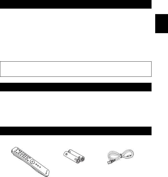
SUPPLIED ACCESSORIES
Please check that you received all of the following parts.
Remote control |
Batteries (x2) |
Power cable |
|
(AA, R6, UM-3) |
|
English
1 En
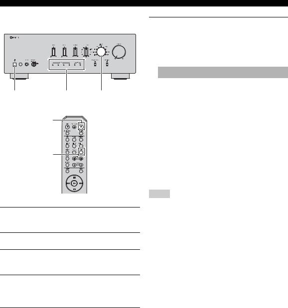
CONTROLS AND FUNCTIONS
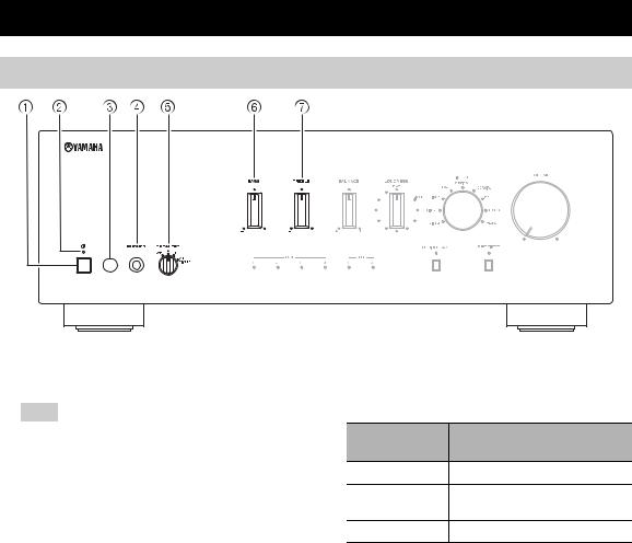
Front panel
1 A(power) switch
Turns on and off the power of this unit.
Note
Even when this unit is turned off, this unit consumes a small amount of power.
2 Power indicator
Indicator |
Status |
|
|
Brightly lit |
The power of this unit is “on”. |
|
|
|
This unit is in “standby” mode. |
Dimly lit |
For details on the “standby” mode, see |
|
page 6. |
|
|
Off |
The power of this unit is “off”. |
|
|
3Remote control sensor
Receives infrared signals from the remote control.
4PHONES jack
Connect your headphones.
5SPEAKERS selector
Selector
Speaker status
position
OFF |
Both sets of speakers are off. |
A or B
The set of speakers connected to the A or B terminals is on.
A+B BI-WIRING Both sets of speakers are on.
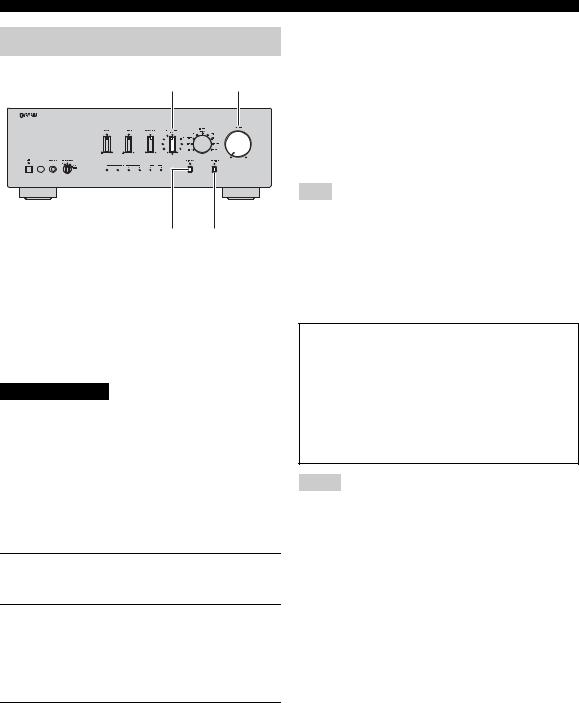
6BASS control
Increases or decreases the low frequency response. The 0 position produces a flat response.
Control range: –10 dB to +10 dB
7TREBLE control
Increases or decreases the high frequency response. The 0 position produces a flat response.
Control range: –10 dB to +10 dB
2 En
CONTROLS AND FUNCTIONS
English
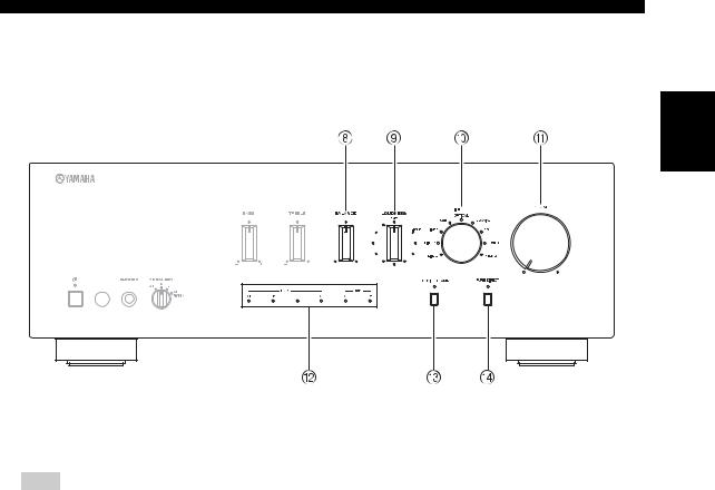
8BALANCE control
Adjusts the sound output balance of the left and right speakers to compensate for sound imbalances.
Note
If you rotate the BALANCE control to the end of L (left) or R (right), the opposite side of channel is muted.
9LOUDNESS control
Retain a full tonal range at any volume level (see page 12).
0INPUT selector and indicators
Selects the input source you want to listen to. The input source indicators light up when the corresponding input sources are selected.
y
The input source names correspond to the names of the connection jacks on the rear panel.
AVOLUME control
Increases or decreases the sound output level.
BUSB DAC Indicators
Lights up when PCM (Pulse Code Modulation) or DSD (Direct Stream Digital) digital audio signals are input to a USB terminal of this unit (see page 14).
CCD DIRECT AMP button and indicator
Reproduces CD sound in the highest signal quality (see page 12).
The indicator above it lights up when this function is turned on.
DPURE DIRECT button and indicator
Reproduces any input source in the purest sound possible (see page 12).
The indicator above it lights up when this function is turned on.
3 En
CONTROLS AND FUNCTIONS
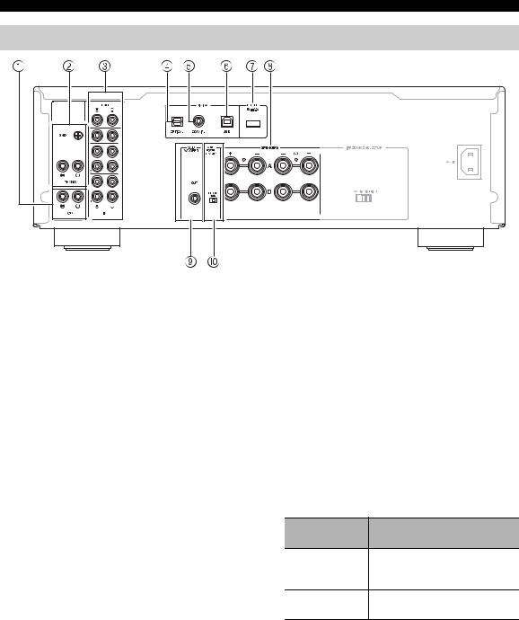
Rear panel
1CD input jacks
Used to connect a CD player (see page 9).
2PHONO jacks and GND terminal
Used to connect a turntable that uses an MM cartridge, and to ground the terminal (see page 9).
3Audio input/output jacks
Used to connect external components, such as a tuner, etc (see page 9).
4DIGITAL (OPTICAL) jack
Used to connect a component with a digital optical output (see page 9).
5DIGITAL (COAXIAL) jack
Used to connect a component with a digital coaxial output (see page 9).
6DIGITAL (USB) jack (Type B)
Used to connect a PC (see page 13).
7DC OUT jack
For supplying power to a Yamaha AV accessory. For details on connections, refer to the instruction manual of the AV accessory.
8SPEAKERS A/B terminals
Used to connect one or two speaker sets (see page 9).
9SUBWOOFER OUT jack
Used to connect a subwoofer with built-in amplifier (see page 9).
y
The SUBWOOFER OUT jack attenuates signals over 90 Hz.
0 AUTO POWER STANDBY switch
Switch
Status
position
The unit enters standby mode ON automatically if not operated for 8
hours.
OFF
The unit does not enter standby mode automatically.
4 En
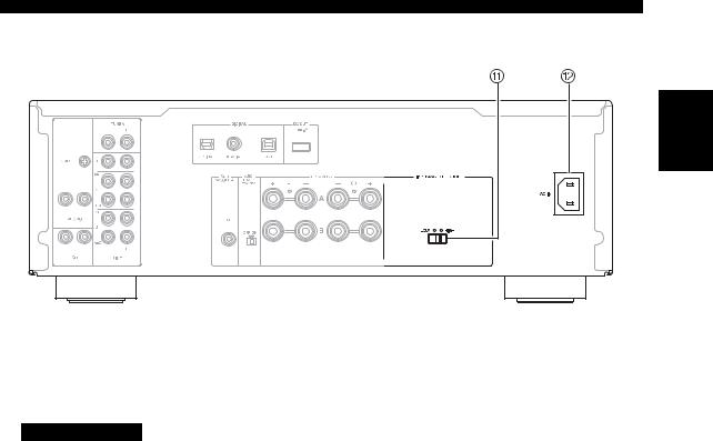
CONTROLS AND FUNCTIONS
English
A IMPEDANCE SELECTOR switch
CAUTION
Do not change the IMPEDANCE SELECTOR switch while the power is turned on, as doing so may damage the unit.
If the IMPEDANCE SELECTOR switch may not be fully slid to either position, remove the power cable and slide the switch all the way to either position.
Select the switch position according to the impedance of the speakers.
Speaker |
Speaker |
Switch |
|
connection |
impedance |
position |
|
|
|
|
|
SPEAKERS A |
6 Ω or higher |
|
|
8 Ω or higher |
HIGH |
||
or |
(Asia model only) |
|
|
SPEAKERS B |
|
|
|
4 Ω or higher |
LOW |
||
|
|||
|
|
|
|
|
12 Ω or higher |
|
|
SPEAKERS A |
(U.K. model only) |
HIGH |
|
16 Ω or higher |
|||
and |
|
||
(Asia model only) |
|
||
SPEAKERS B |
|
||
|
|
||
|
8 Ω or higher |
LOW |
|
|
|
|
|
|
6 Ω or higher |
|
|
Bi-wiring |
8 Ω or higher |
HIGH |
|
(Asia model only) |
|
||
|
|
|
|
|
4 Ω or higher |
LOW |
|
|
|
|
BAC IN
Used to connect the supplied power cable to an AC wall outlet (see page 10).
5 En
CONTROLS AND FUNCTIONS
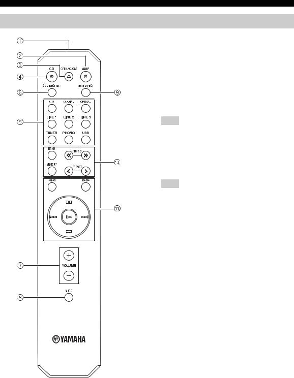
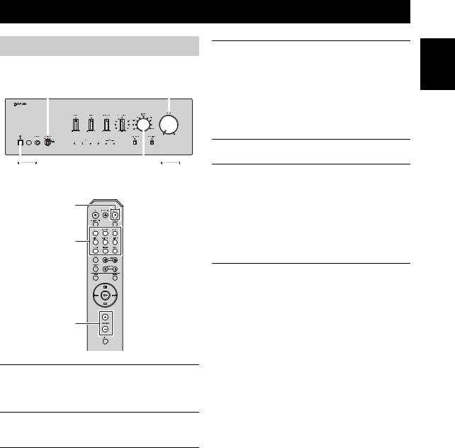
Remote control
1 Infrared signal transmitter
Sends infrared signals.
2 AAMP
Turns this unit on, or sets it to standby mode.
3  OPEN/CLOSE
Opens/closes the disc tray of the Yamaha CD player. Refer to the owner’s manual of your CD player for
details.
Note
Even when using a Yamaha CD player, certain components and features may not be available.
4 ACD
Turns the Yamaha CD player on, or sets it to standby mode. Refer to the owner’s manual of your CD player
for details.
Note
Even when using a Yamaha CD player, certain components and features may not be available.
5 CD DIRECT AMP
Reproduces CD sound in the highest signal quality (see page 12).
6 Input selector buttons
Selects the input source you want to listen to.
y
The input source names correspond to the names of the connection jacks on the rear panel.
7 VOLUME +/–
Increases or decreases the sound output level.
8 MUTE
Reduces the current volume level by approximately 20 dB. Press again to restore the audio output to the previous volume level. Pressing the VOLUME +/– also cancels muting.
The input indicator on the front panel for the current input source blinks while the output is muted.
9 PURE DIRECT
Reproduces any input source in the purest sound possible (see page 12).
6 En
|
CONTROLS AND FUNCTIONS |
0 Yamaha tuner control buttons |
A Yamaha CD player control buttons |
The following buttons can be used to control various functions of a Yamaha tuner.
Refer to your component’s owner’s manual for more information.
BAND
Selects the reception band (FM/AM).
TUNING jj/ ii
Selects the tuning frequency.
MEMORY
Stores the current FM/AM station as a preset.
PRESET j/ i
Selects a preset FM/AM station.
Note
Even when using a Yamaha tuner, certain components and features may not be available.
The following buttons can be used to control a Yamaha CD player.
Refer to your component’s owner’s manual for more information.
w |
Rewinds playback |
f |
Fast-forwards playback |
e |
Pauses playback |
b |
Skips backward |
a |
Skips forward |
p |
Starts playback |
s |
Stops playback |
Note
Even when using a Yamaha CD player, certain components and features may not be available.
English
7 En
CONTROLS AND FUNCTIONS
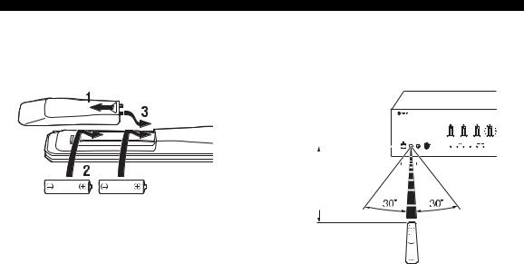
■ Installing batteries |
■ Operation range |
|||||||||||
|
|
|
Point the remote control at the remote control sensor on |
|||||||||
|
|
|
this unit and remain within the operating range shown |
|||||||||
|
|
|
below. |
|||||||||
|
|
|
|
|
|
|
|
|
|
|
|
|
|
|
|
|
|
|
|
|
|
|
|
|
|
|
|
|
|
|
|
|
|
|
|
|
|
|
|
|
|
|
|
|
|
|
|
|
|
|
|
|
|
|
|
|
|
|
|
|
|
|
|
|
|
|
|
|
|
|
|
|
|
|
|
|
|
|
|
|
|
|
|
|
|
|
|
|
|
|
|
Approximately |
|
6 m |
AA, R6, UM-3 batteries |
(20 ft) |
|
Remote control
■Notes on remote control and batteries
•The area between the remote control and this unit must be clear of large obstacles.
•Be careful not to spill water or other liquids on the remote control.
•Be careful not to drop the remote control.
•Do not leave or store the remote control in the following conditions:
–places of high humidity, such as near a bathroom
–places of high temperatures, such as near a heater or stove
–places of extremely low temperatures
–dusty places
•Change all batteries if you notice the operation range of the remote control narrows.
•If the batteries run out, immediately remove them from the remote control to prevent an explosion or acid leak.
•If you find leaking batteries, discard the batteries immediately, taking care not to touch the leaked material. If the leaked material comes into contact with your skin or gets into your eyes or mouth, rinse it away immediately and consult a doctor. Clean the battery compartment thoroughly before installing new batteries.
•Do not use old batteries together with new ones. This may shorten the life of the new batteries or cause old batteries to leak.
•Do not use different types of batteries (such as alkaline and manganese batteries) together. Batteries that look the same may have a different specification.
•Dispose of batteries according to your regional regulations.
•Keep the batteries in a location out of reach of children.
Batteries can be dangerous if a child were to put in his or her mouth.
•If you plan not to use this unit for a long period of time, remove the batteries from this unit. Otherwise, the batteries will wear out, possibly resulting in a leakage of battery liquid that may damage this unit.
8 En
CONNECTIONS
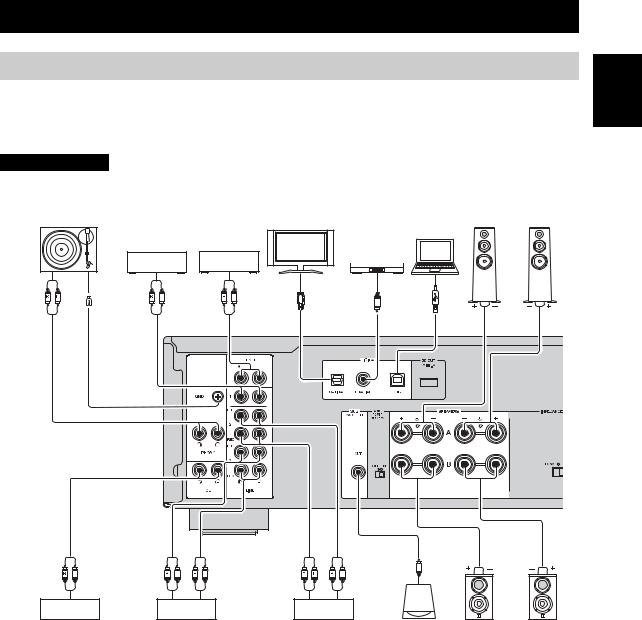
Connecting speakers and source components
Make sure to connect L (left) to L, R (right) to R, “+” to “+” and “–” to “–”. If the connections are faulty, no sound will be heard from the speakers, and if the polarity of the speaker connections is incorrect, the sound will be unnatural and lack bass. Refer to the owner’s manual for each of your components.
Make sure to use RCA cables, optical cable or USB cables to connect audio components.
CAUTION
Do not connect this unit or other components to the main power until all connections between components are complete.
Turntable |
TV, etc. |
DVD player, |
PC |
|
|
etc. |
Tuner |
|
BD player, etc. |
Audio |
GND |
Audio |
Audio |
Audio |
Audio |
Audio |
out |
out |
out |
out |
out |
out |
Speakers A
Right Left
English
Audio |
Audio |
Audio |
Audio |
Audio |
|
|
|
out |
out |
In |
In |
|
out |
|
|
CD player |
|
Tape deck, |
CD recorder, |
Subwoofer |
Right |
Left |
|
|
|
etc. |
|
etc. |
|
Speakers B |
|
|
|
|
|
|
|
||
Only PCM signals can be input to the DIGITAL (OPTICAL/COAXIAL) jacks of this unit. For details on the supported PCM signals, see page 18.
y
•The PHONO jacks are designed for connecting a turntable with an MM cartridge.
•Connect your turntable to the GND terminal to reduce noise in the signal. However, for some turntables, you may hear less noise without the GND connection.
9 En
CONNECTIONS
■ REC jacks
•The audio signals are not output via the LINE 2 REC or LINE 3 REC output jacks when LINE 2 or LINE 3 is selected with the INPUT selector.
•The VOLUME, BASS, TREBLE, BALANCE and LOUDNESS controls and the CD DIRECT function (or the PURE DIRECT function) have no effect on the source being recorded.
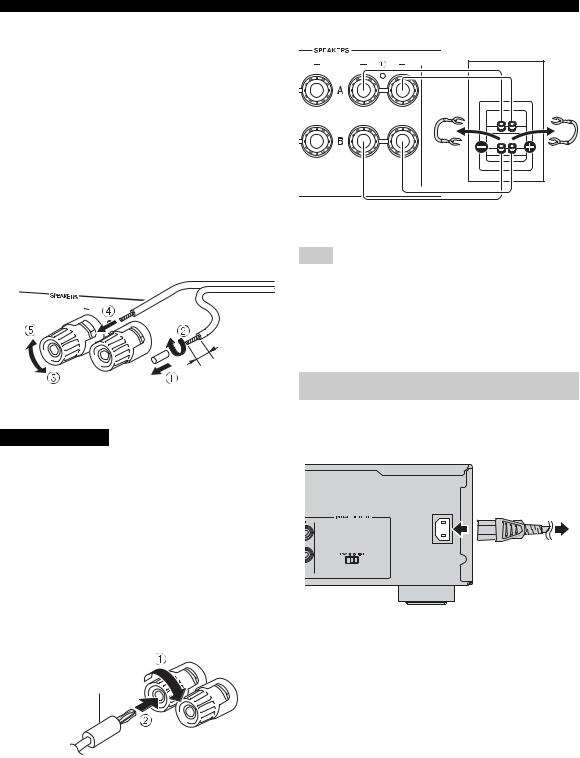
■ Connecting speaker cables
1Remove approximately 10 mm (3/8 in) of insulation from the end of each speaker cable.
2Twist the bare wires of the cable firmly together.
3Unscrew the knob.
4Insert one bare wire into the hole in the side of each terminal.
5Tighten the knob to secure the wire.
10 mm (3/8 in)
Red: positive (+)
Black: negative (–)
CAUTION
•Set the IMPEDANCE SELECTOR switch according to the impedance of the speakers to be connected (see page 5).
•Do not let bare speaker wires touch each other or any metal part of this unit. This could damage this unit and/ or the speakers.
■Connecting via banana plug
(North America, China and Australia
models only)
1Tighten the knob.
2Insert the banana plug into the end of the corresponding terminal.
Rear panel
Speaker
Connect the other speaker to the other set of terminals in the same way.
Note
When making bi-wire connections, remove the shorting bridges or cables on the speaker. Refer to the speakers’ instruction manuals for more information.
y
To use the bi-wire connections, set the SPEAKERS selector on the front panel to the A+B BI-WIRING position.
Connecting power cable
Plug the power cable into the AC IN inlet when all connections are complete, and then plug in the power cable to the AC outlet.
To the AC wall outlet
Banana plug
■ Bi-wire connection
In the case of speakers supporting the bi-wiring connection, the tweeter/midrange unit and woofer of the speakers can be driven independently through connections shown in the following figure, allowing you to enjoy clear midand high-range sounds.
10 En
PLAYBACK
Playing a source
|
SPEAKERS |
VOLUME |
||||||||
|
|
|
|
|
|
|
|
|
|
|
|
|
|
|
|
|
|
|
|
|
|
|
|
|
|
|
|
|
|
|
|
|
|
|
|
|
|
|
|
|
|
|
|
|
|
|
|
|
|
|
|
|
|
|
|
|
|
|
|
|
|
|
|
|
|
|
|
|
|
|
|
|
|
|
|
|
|
|
|
|
|
|
|
|
|
|
|
A |
INPUT |
AAMP
Input selector buttons
VOLUME +/–
4Rotate the SPEAKERS selector on the front panel to select SPEAKERS A, B or A+B BIWIRING.
y
Set the SPEAKERS selector to the A+B BI-WIRING position when two sets of speakers are connected using bi-wire connections, or when using two sets of speakers simultaneously (A and B).
5Play the selected input source.
6Rotate the VOLUME control on the front panel (or press VOLUME +/– on the remote control) to adjust the sound output level.
y
You can adjust to the desired sound by using the BASS, TREBLE, BALANCE and LOUDNESS controls, the CD DIRECT AMP button, or the PURE DIRECT button on the front panel.
7When finished listening, press A(power) switch on the front panel outward to turn off this unit.
y
If AAMP on the remote control is pressed while the A(power) switch on the front panel is in the on position, this unit enters standby mode. Press AAMP again to turn this unit on.
1Rotate the VOLUME control on the front panel fully counter-clockwise so as not to play sounds loud suddenly.
2Press A(power) switch on the front panel inward to turn on this unit.
3Rotate the INPUT selector on the front panel (or press one of the Input selector buttons on the remote control) to select the input source you want to listen to.
The indicator for the selected input source lights up.
y
If you want to play back the music stored on your PC, select USB as the input source (see page 13).
English
11 En
PLAYBACK
Adjusting to the desired sound
LOUDNESS VOLUME
CD DIRECT PURE
AMP DIRECT
■Making it easier to hear the highand low-frequency ranges even at low
volume (LOUDNESS)
Enjoy natural sound even at low volume by lowering the mid-range sound level and compensating for the human ears’ loss of sensitivity to highand low-frequency ranges at low volume.
CAUTION
If the CD DIRECT AMP function (or the PURE DIRECT function) is turned on with the LOUDNESS control set at a certain level, the input signals bypass the loudness control, resulting in a sudden increase in the sound output level. To prevent your ears or the speakers from being damaged, be sure to press the CD DIRECT AMP button (or the PURE DIRECT button) AFTER lowering the sound output level or AFTER checking that the LOUDNESS control is properly set.
1Set the LOUDNESS control to the FLAT position.
2Rotate the VOLUME control on the front panel (or press VOLUME +/– on the remote control) to set the sound output level to the loudest listening level that you would listen to.
3Rotate the LOUDNESS control counterclockwise until the desired volume is obtained.
■ Reproducing pure, high fidelity sound
(PURE DIRECT)
When the PURE DIRECT function is on, noise can be reduced by bypassing the circuit that the audio input signal is not using and stopping the power supply to the circuit.
Therefore, in all input sources, you can enjoy music playback in straight and high quality sound.
The indicator above the PURE DIRECT button lights up when this function is turned on.
Note
The BASS, TREBLE, BALANCE and LOUDNESS controls do not function while the PURE DIRECT function is turned on.
■ Reproducing CD sound with the highest sound quality (CD DIRECT AMP)
When selecting the input source other than CD, if you press the CD DIRECT AMP button, the input source switches to CD.
CD Direct Amp feature
Stop power supply to the unnecessary circuit for CD playback, convert the input signal to the normal phase and reverse phase, and balance transfer to the electronic volume. With the following effects, a more faithful sound to the original will be provided.
•improved signal-to-noise ratio
•external noise canceling
•reduced distortion
Notes
•The BASS, TREBLE, BALANCE and LOUDNESS controls do not function while the CD DIRECT AMP function is turned on.
•Be sure to connect the CD player to the CD input jacks if you use the CD direct function.
•The CD DIRECT AMP function is turned off if the following operation is performed.
–Select an input source other than CD for the INPUT selector.
–The PURE DIRECT function is turned on.
12 En

PLAYBACK OF MUSIC FILES STORED ON A PC (USB DAC)
When a PC is connected to the DIGITAL (USB) jack of
this unit, the unit functions as a USB DAC, enabling music files stored on the PC to be played.
Rear panel
USB cable (Type B)
PC
■ Supported operating systems
The USB connection with this unit is for PCs with the following operating systems:
Windows: Windows 7 (32 bit/64 bit)/ Windows 8 (32 bit/64 bit)/ Windows 8.1 (32 bit/64 bit)
Mac: OS X 10.6.8/10.7.x/10.8.x/10.9.x
Notes
•Operations with other operating systems are not guaranteed.
•Operations may be disabled even with the above-mentioned operating systems, depending on the configuration or environment of the PC.
•Operations may not be executed correctly if the PC is connected to this unit before the driver is installed.
■ Installing the dedicated driver
Before connecting a PC to this unit, install the dedicated driver on the PC.
1Access the following URL, download the dedicated “Yamaha Steinberg USB Driver,” then extract and execute the file.
Website for downloading the exclusive driver URL: http://download.yamaha.com/
2Install the downloaded “Yamaha Steinberg USB Driver” on the PC.
For details, refer to the Installation Guide supplied with the downloaded driver.
3When installation is complete, quit all running applications.
4Set the audio output destination of the computer to “Yamaha USB DAC”
With Windows OS:
Control Panel Hardware and Sound Sound [Playback] tab
With Mac OS:
System Preferences Sound [Output] tab
The setting may vary, depending on the operating system. For details, consult the manufacturer of your PC.
y
Transmittable sampling frequencies are as follows:
PCM: 44.1 kHz/48 kHz/88.2 kHz/96 kHz/176.4 kHz/192 kHz/ 352.8 kHz/384 kHz
DSD: 2.8224 MHz/5.6448 MHz
Notes
•Operations may not be executed correctly if the PC is connected to this unit before the driver is installed.
•The “Yamaha Steinberg USB Driver” is subject to change without prior notice. For details and the latest information, refer to the download page for the driver.
English
13 En
PLAYBACK OF MUSIC FILES STORED ON A PC (USB DAC)
■Playing back music files stored on the PC
A |
USB DAC |
INPUT |
|
indicators |
|
|
AAMP |
|
USB
1Connect the PC to this unit, using a USB cable.
2Turn on the PC.
3Press A(power) switch on the front panel inward to turn on this unit.
4Rotate the INPUT selector on the front panel (or press one of the Input selector buttons on the remote control) to select the USB.
5Set the audio output destination of the PC to “Yamaha USB DAC”
With Windows OS:
Control Panel Hardware and Sound Sound [Playback] tab
With Mac OS:
System Preferences Sound [Output] tab
The setting may vary, depending on the operating system. For details, consult the manufacturer of your PC.
6Operate the PC to start playback of music files.
When the music signal input from the PC to the unit, the USB DAC indicator on the front panel lights up in accordance with the sampling frequency of the song being played.
Indicator |
Frequency |
||
|
|
||
|
× 1 |
44.1/48 kHz |
|
|
|
|
|
PCM |
× 2 |
88.2/96 kHz |
|
|
|
||
× 4 |
176.4/192 kHz |
||
|
|||
|
|
|
|
|
× 8 |
352.8/384 kHz |
|
|
|
|
|
DSD |
× 1 |
2.8224 MHz |
|
|
|
||
× 2 |
5.6448 MHz |
||
|
|||
|
|
|
|
■ Adjusting the sound volume
To obtain higher sound quality, set the sound volume at the PC to the maximum, and gradually increase the volume at this unit from the minimum to your desired level.
Notes
•Do not disconnect the USB cable, turn off the unit, or change the input while playback on a PC connected via the USB cable is in progress. Doing so may cause a malfunction.
•To mute operation sounds of the PC during music playback, change the setting on the PC.
•If music files cannot be played correctly, restart the computer and perform the mentioned procedure again.
•The music files stored on a PC cannot be controlled from this unit or the remote control of this unit. Operate them on the PC.
14 En

TROUBLESHOOTING
Refer to the chart below if this unit does not function properly. If the problem you are experiencing is not listed below or if the instructions below do not help, turn off this unit, disconnect the power cable, and then contact the nearest authorized Yamaha dealer or service center.
Problem |
Cause |
Remedy |
See |
|
page |
||||
|
|
|
||
|
|
|
|
|
This unit fails to turn |
The power cable is not connected or the |
Connect the power cable firmly. |
10 |
|
on. |
plug is not completely inserted. |
|
||
|
|
|||
|
|
|
|
|
|
The AAMP is pressed on the remote |
Press A(power) switch on the front panel to on. |
2 |
|
|
control while this unit is turned off. |
|
||
|
|
|
||
|
|
|
|
|
|
The impedance setting of the connected |
Use speaker(s) with proper speaker impedance. |
5 |
|
|
speaker is too small. |
|
||
|
|
|
||
|
|
|
|
|
|
The protection circuitry has been activated |
Check that the speaker wires are not touching each |
10 |
|
|
because of a short circuit, etc. |
other and then turn the power of this unit back on. |
||
|
|
|||
|
|
|
|
|
|
There is a problem with the internal |
Disconnect the power cable and contact the nearest |
— |
|
|
circuitries of this unit. |
authorized Yamaha dealer or service center. |
||
|
|
|||
|
|
|
|
|
This unit turns off |
The speaker wires are touching each other |
Connect the speaker cables properly and press the A |
|
|
suddenly and the |
or shorting out against the rear panel. |
(power) switch again. The INPUT indicators blink |
|
|
power indicator |
|
and the volume is decreased to the lowest setting |
10 |
|
blinks. |
|
automatically, then the INPUT indicators stop |
||
|
|
flashing and the last input source selected lights up. |
|
|
|
|
Confirm normal sound output from speakers by |
|
|
|
|
increasing the volume gradually. |
|
|
|
|
|
|
|
|
The speaker is malfunctioning. |
Replace the speaker set and press the A(power) |
|
|
|
|
switch again. The INPUT indicators blink and the |
|
|
|
|
volume is decreased to the lowest setting |
— |
|
|
|
automatically, then the INPUT indicators stop |
||
|
|
flashing and the last input source selected lights up. |
|
|
|
|
Confirm normal sound from speakers by increasing |
|
|
|
|
the volume gradually. |
|
|
|
|
|
|
|
|
The protection circuitry has been activated |
Rotate the VOLUME control on the front panel to |
— |
|
|
because of excessive input or excessive |
decrease the volume level and then turn the power on |
||
|
volume level. |
again. |
|
|
|
|
|
|
|
|
The protection circuitry has been activated |
Allow about 30 minutes for the temperature inside |
|
|
|
due to excessive internal temperature. |
this unit to decrease, rotate the VOLUME control on |
— |
|
|
|
the front panel to lower the volume and then turn the |
||
|
|
power on again. Set the unit in a place where heat can |
|
|
|
|
readily dissipate from the unit. |
|
|
|
|
|
|
|
|
The IMPEDANCE SELECTOR switch is |
Turn the power off and slide the IMPEDANCE |
5 |
|
|
not fully slid to either position. |
SELECTOR switch all the way to the correct position. |
||
|
|
|||
|
|
|
|
|
|
The IMPEDANCE SELECTOR switch is |
Set the IMPEDANCE SELECTOR switch to the |
5 |
|
|
not set to the correct position. |
position that corresponds to the impedance of your |
||
|
|
speakers. |
|
|
|
|
|
|
|
|
This unit has been exposed to a strong |
Turn off this unit, disconnect the power cable, plug it |
— |
|
|
external electric shock (such as lightning |
back in after 30 seconds, then use the unit normally. |
||
|
or strong static electricity). |
|
|
|
|
|
|
|
|
|
There is a problem with the internal |
Disconnect the power cable and contact the nearest |
— |
|
|
circuitries of this unit. |
authorized Yamaha dealer or service center. |
||
|
|
|||
|
|
|
|
|
No sound. |
Sound is muted. |
Press MUTE on the remote control or rotate the |
6 |
|
|
|
VOLUME control. |
||
|
|
|
||
|
|
|
|
|
|
Incorrect cable connections. |
Connect the stereo cable for audio units and the |
9 |
|
|
|
speaker wires properly. If the problem persists, the |
||
|
|
cables may be defective. |
|
|
|
|
|
|
English
15 En

TROUBLESHOOTING
Problem |
Cause |
Remedy |
See |
|
page |
||||
|
|
|
||
|
|
|
|
|
No sound. |
Playback has been stopped on the |
Turn the component on and start playback. |
11 |
|
|
connected component. |
|
||
|
|
|
||
|
|
|
|
|
|
No appropriate input source has been |
Select an appropriate input source with the INPUT |
11 |
|
|
selected. |
selector on the front panel (or one of the Input |
||
|
|
selector buttons on the remote control). |
|
|
|
|
|
|
|
|
The SPEAKERS selector is not set |
Set the corresponding SPEAKERS selector to A, B or |
11 |
|
|
properly. |
A+B BI-WIRING position. |
||
|
|
|||
|
|
|
|
|
|
The output audio source setting on the |
Only PCM audio sources can be played via the |
|
|
|
connected component is not PCM. |
DIGITAL (OPTICAL/COAXIAL) jacks of this unit. |
18 |
|
|
|
Set the output audio source of the connected |
||
|
|
|
||
|
|
component to PCM. |
|
|
|
|
|
|
|
The sound suddenly |
The automatic power down function has |
Confirm that there are no other issues causing this |
|
|
goes off. |
activated. |
problem, and then turn this unit on again. |
4 |
|
|
|
To turn off the AUTO POWER STANDBY function, |
||
|
|
set the AUTO POWER STANDBY switch to OFF on |
|
|
|
|
the rear panel. |
|
|
|
|
|
|
|
Only the speaker on |
Incorrect cable connections. |
Connect the cables properly. If the problem persists, |
9 |
|
one side can be |
|
the cables may be defective. |
||
|
|
|||
heard. |
|
|
|
|
Incorrect setting for the BALANCE |
Set the BALANCE control to the appropriate |
3 |
||
|
||||
|
control. |
position. |
||
|
|
|||
|
|
|
|
|
There is a lack of bass |
The + and – wires are connected in |
Connect the speaker wires to the correct + and – |
10 |
|
and no ambience. |
reverse at the amplifier or the speakers. |
phase. |
||
|
||||
|
|
|
|
|
A “humming” sound |
Incorrect cable connections. |
Connect the audio plugs firmly. If the problem |
9, 10 |
|
can be heard. |
|
persists, the cables may be defective. |
||
|
|
|||
|
|
|
|
|
|
No connection from the turntable to the |
Make the GND connection between the turntable and |
9 |
|
|
GND terminal. |
this unit. |
||
|
|
|||
|
|
|
|
|
The volume level |
The component connected to the LINE 2 |
Turn on the power of the component. |
|
|
cannot be increased, |
REC or LINE 3 REC jacks of this unit is |
|
— |
|
or the sound is |
turned off. |
|
||
|
|
|||
distorted. |
|
|
|
|
|
|
|
|
|
The sound is |
This unit is turned off or is in standby |
Turn on the power of this unit. |
|
|
degraded when |
mode. |
|
|
|
listening with |
|
|
— |
|
headphones |
|
|
||
connected to a CD |
|
|
|
|
player connected to |
|
|
|
|
this unit. |
|
|
|
|
|
|
|
|
|
The sound level is |
Sound is muted. |
Press MUTE on the remote control or rotate the |
6 |
|
low. |
|
VOLUME control. |
||
|
|
|||
|
|
|
|
|
|
The loudness control function is |
Turn down the volume, set the LOUDNESS control |
12 |
|
|
operating. |
to the FLAT position, and then adjust the volume |
||
|
|
again. |
|
|
|
|
|
|
|
The volume level is |
The turntable is connected to the jacks |
Connect the turntable to the PHONO jacks. |
9 |
|
low while playing a |
other than the PHONO jacks. |
|
||
|
|
|||
record. |
|
|
|
|
The record is being played on a turntable |
Use a turntable equipped with an MM cartridge. |
9 |
||
|
||||
|
with an MC cartridge. |
|
||
|
|
|
||
|
|
|
|
|
Using the BASS, |
The CD DIRECT function or the PURE |
The CD DIRECT function or the PURE DIRECT |
|
|
TREBLE, BALANCE |
DIRECT function is turned on. |
function must be turned off to use those controls. |
12 |
|
and LOUDNESS |
|
|
||
controls does not |
|
|
|
|
affect the sound. |
|
|
|
|
|
|
|
|
16 En
 Loading...