


U
Integrated Amplifier
Amplificateur Intégré
OWNER’S MANUAL
MODE D’EMPLOI
IMPORTANT SAFETY INSTRUCTIONS
CAUTION |
RISK OF ELECTRIC SHOCK |
DO NOT OPEN |
CAUTION: TO REDUCE THE RISK OF |
ELECTRIC SHOCK, DO NOT REMOVE |
COVER (OR BACK). NO USER-SERVICEABLE |
PARTS INSIDE. REFER SERVICING TO |
QUALIFIED SERVICE PERSONNEL. |
• Explanation of Graphical Symbols
The lightning flash with arrowhead symbol, within an equilateral triangle, is intended to alert you to the presence of uninsulated “dangerous voltage” within the product’s enclosure that may be of sufficient magnitude to constitute a risk of electric shock to persons.
The exclamation point within an equilateral triangle is intended to alert you to the presence of important operating and maintenance (servicing) instructions in the literature accompanying the appliance.
IMPORTANT
Please record the serial number of this unit in the space below.
MODEL:
Serial No.:
The serial number is located on the rear of the unit. Retain this Owner’s Manual in a safe place for future reference.
1Read these instructions.
2Keep these instructions.
3Heed all warnings.
4Follow all instructions.
5Do not use this apparatus near water.
6Clean only with dry cloth.
7Do not block any ventilation openings. Install in accordance with the manufacturer’s instructions.
8Do not install near any heat sources such as radiators, heat registers, stoves, or other apparatus (including amplifiers) that produce heat.
9Do not defeat the safety purpose of the polarized or grounding-type plug. A polarized plug has two blades with one wider than the other. A grounding type plug has two blades and a third grounding prong. The wide blade or the third prong are provided for your safety. If the provided plug does not fit into your outlet, consult an electrician for replacement of the obsolete outlet.
10Protect the power cord from being walked on or pinched particularly at plugs, convenience receptacles, and the point where they exit from the apparatus.
11Only use attachments/accessories specified by the manufacturer.
12Use only with the cart, stand, tripod, bracket, or table specified by the
manufacturer, or sold with the apparatus. When a cart is used, use caution when moving the cart/apparatus combination to avoid injury from tip-over.
13Unplug this apparatus during lightning storms or when unused for long periods of time.
14Refer all servicing to qualified service personnel. Servicing is required when the apparatus has been damaged in any way, such as power-supply cord or plug is damaged, liquid has been spilled or objects have fallen into the apparatus, the apparatus has been exposed to rain or moisture, does not operate normally, or has been dropped.
We Want You Listening For A Lifetime
Yamaha and the Electronic Industries Association’s Consumer Electronics Group want you to get the most out of your equipment by playing it at a safe level. One that lets the sound come through loud and clear without annoying blaring or distortion – and, most importantly, without affecting your sensitive hearing. Since hearing damage from loud sounds is often undetectable until it is too late, Yamaha and the Electronic Industries Association’s Consumer Electronics Group recommend you to avoid prolonged exposure from excessive volume levels.
i En

|
|
IMPORTANT SAFETY INSTRUCTIONS |
|
|
|
|
|
|
FCC INFORMATION (for US customers) |
||
|
|
|
|
|
1 IMPORTANT NOTICE: DO NOT MODIFY THIS |
Compliance with FCC regulations does not guarantee |
|
|
UNIT! |
that interference will not occur in all installations. If |
|
|
This product, when installed as indicated in the |
this product is found to be the source of interference, |
|
|
instructions contained in this manual, meets FCC |
which can be determined by turning the unit “OFF” |
|
|
requirements. Modifications not expressly approved by |
and “ON”, please try to eliminate the problem by using |
|
|
Yamaha may void your authority, granted by the FCC, |
one of the following measures: |
|
|
to use the product. |
Relocate either this product or the device that is being |
|
|
2 IMPORTANT: When connecting this product to |
||
|
affected by the interference. |
||
|
accessories and/or another product use only high quality |
||
|
Utilize power outlets that are on different branch |
||
|
shielded cables. Cable/s supplied with this product MUST |
||
|
be used. Follow all installation instructions. Failure to |
(circuit breaker or fuse) circuits or install AC line |
|
|
follow instructions could void your FCC authorization to |
filter/s. |
|
|
use this product in the USA. |
In the case of radio or TV interference, relocate/ |
|
|
3 NOTE: This product has been tested and found to comply |
reorient the antenna. If the antenna lead-in is 300 ohm |
|
|
ribbon lead, change the lead-in to coaxial type cable. |
||
|
with the requirements listed in FCC Regulations, Part 15 |
||
|
|
|
|
|
for Class “B” digital devices. Compliance with these |
If these corrective measures do not produce |
|
|
requirements provides a reasonable level of assurance that |
satisfactory results, please contact the local retailer |
|
|
your use of this product in a residential environment will |
authorized to distribute this type of product. If you can |
|
|
not result in harmful interference with other electronic |
not locate the appropriate retailer, please contact |
|
|
devices. |
Yamaha Corporation of America A/V Division, 6600 |
|
|
This equipment generates/uses radio frequencies and, |
Orangethorpe Avenue, Buena Park, CA 90620, USA. |
|
|
if not installed and used according to the instructions |
The above statements apply ONLY to those products |
|
found in the users manual, may cause interference |
distributed by Yamaha Corporation of America or its |
|
harmful to the operation of other electronic devices. |
||
subsidiaries. |
||
|
FOR CANADIAN CUSTOMERS
To prevent electric shock, match wide blade of plug to wide slot and fully insert.
CAN ICES-3 (B)/NMB-3(B)
ii En
CAUTION: READ THIS BEFORE OPERATING YOUR UNIT.
1To assure the finest performance, please read this manual carefully. Keep it in a safe place for future reference.
2Install this sound system in a well ventilated, cool, dry, clean place - away from direct sunlight, heat sources, vibration, dust, moisture, and/or cold. For proper ventilation, allow the following minimum clearances around this unit.
Top: 30 cm (11-3/4 in) Rear: 20 cm (7-7/8 in) Sides: 20 cm (7-7/8 in)
3Locate this unit away from other electrical appliances, motors, or transformers to avoid humming sounds.
4Do not expose this unit to sudden temperature changes from cold to hot, and do not locate this unit in an environment with high humidity (i.e. a room with a humidifier) to prevent condensation inside this unit, which may cause an electrical shock, fire, damage to this unit, and/or personal injury.
5Avoid installing this unit where foreign object may fall onto this unit and/or this unit may be exposed to liquid dripping or splashing. On the top of this unit, do not place:
–Other components, as they may cause damage and/or discoloration on the surface of this unit.
–Burning objects (i.e. candles), as they may cause fire, damage to this unit, and/or personal injury.
–Containers with liquid in them, as they may fall and liquid may cause electrical shock to the user and/or damage to this unit.
6Do not cover this unit with a newspaper, tablecloth, curtain, etc. in order not to obstruct heat radiation. If the temperature inside this unit rises, it may cause fire, damage to this unit, and/or personal injury.
7Do not plug in this unit to an AC wall outlet until all connections are complete.
8Do not operate this unit upside-down. It may overheat, possibly causing damage.
9Do not use force on switches, knobs and/or cords.
10When disconnecting the power cable from the AC wall outlet, grasp the plug; do not pull the cable.
11Do not clean this unit with chemical solvents; this might damage the finish. Use a clean, dry cloth.
12Only voltage specified on this unit must be used. Using this unit with a higher voltage than specified is dangerous and may cause fire, damage to this unit, and/or personal injury. Yamaha will not be held responsible for any damage resulting from use of this unit with a voltage other than specified.
13To prevent damage by lightning, keep the power cable and outdoor antennas disconnected from an AC wall outlet or this unit during a lightning storm.
14Do not attempt to modify or fix this unit. Contact qualified Yamaha service personnel when any service is needed. The cabinet should never be opened for any reasons.
15When not planning to use this unit for long periods of time (i.e. vacation), disconnect the AC power plug from the AC wall outlet.
16Be sure to read the “TROUBLESHOOTING” section on common operating errors before concluding that this unit is faulty.
17Before moving this unit, press A(power) to set this unit to standby mode, and then disconnect the AC power plug from the AC wall outlet.
18Condensation will form when the surrounding temperature changes suddenly. Disconnect the power cable from the outlet, then leave this unit alone.
19When using this unit for a long time, this unit may become warm. Turn the power off, then leave this unit alone for cooling.
20Install this unit near the AC wall outlet and where the AC power plug can be reached easily.
21The batteries shall not be exposed to excessive heat such as sunshine, fire or the like.
22Excessive sound pressure from earphones and headphones can cause hearing loss.
This unit is not disconnected from the AC power source as long as it is connected to the AC wall outlet, even if this unit itself is turned off by A. This state is called the standby mode. In this state, this unit is designed to consume a very small quantity of power.
WARNING
TO REDUCE THE RISK OF FIRE OR ELECTRIC SHOCK, DO NOT EXPOSE THIS UNIT TO RAIN OR MOISTURE.
This label is required to be attached to a product of which the temperature of the top cover may be hot during operation.
iii En
CONTENTS
USEFUL FEATURES ................................... |
1 |
SUPPLIED ACCESSORIES......................... |
1 |
CONTROLS AND FUNCTIONS................. |
2 |
Front panel ........................................................ |
2 |
Rear panel ......................................................... |
4 |
Remote control.................................................. |
6 |
CONNECTIONS............................................ |
9 |
Connecting speakers and source components... |
9 |
Connecting power cable.................................. |
10 |
PLAYBACK................................................. |
11 |
Playing a source ............................................. |
11 |
Adjusting to the desired sound....................... |
12 |
TROUBLESHOOTING.............................. |
13 |
SPECIFICATIONS ..................................... |
15 |
About this manual
•yindicates a tip for your operation.
•The illustrations used in this Owner’s Manual are A-S701.
•Depending on the model, there are some countries/regions where it may not be sold.
USEFUL FEATURES
This unit allows you to:
Enjoy the highest sound quality of compact discs by using the CD direct function (A-S701 only)
(see page 12)
Enjoy pure, high fidelity sound by using the Pure Direct function (see page 12)
Save power by using AUTO POWER STANDBY switch (see page 4)
Use the remote control of this unit to operate a Yamaha tuner and/or CD player (see page 7)
Boost bass sounds by connecting a subwoofer (see page 9)
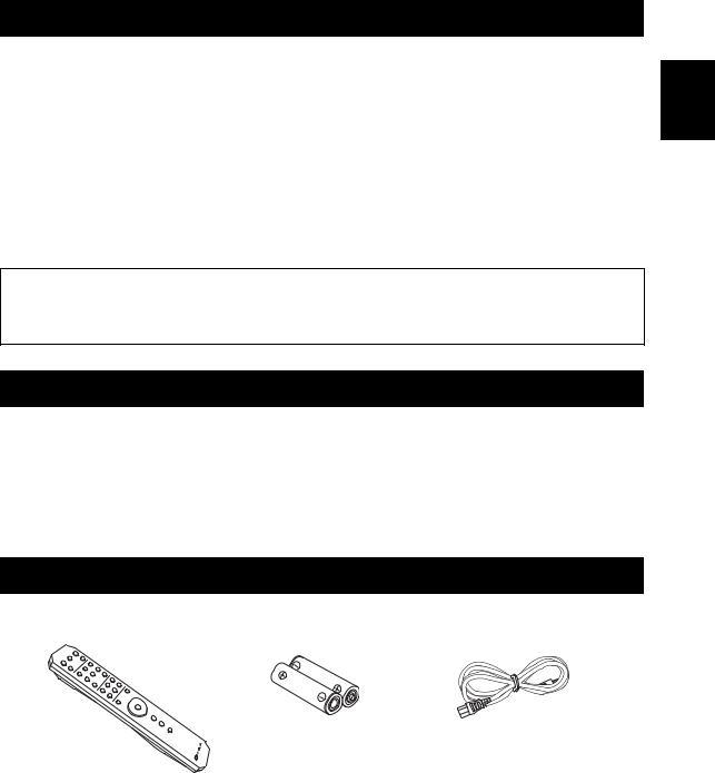
SUPPLIED ACCESSORIES
Please check that you received all of the following parts.
Remote control |
Batteries (x2) |
Power cable |
|
(AA, R6, UM-3) |
(A-S701 only) |
English
1 En
CONTROLS AND FUNCTIONS
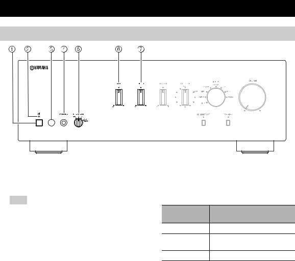
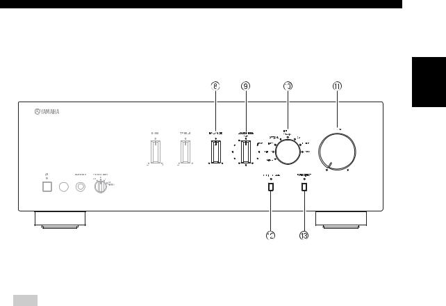
Front panel
1 A(power) switch
Turns on and off the power of this unit.
Note
Even when this unit is turned off, this unit consumes a small amount of power.
2 Power indicator
Indicator |
Status |
|
|
Brightly lit |
The power of this unit is “on”. |
|
|
|
This unit is in “standby” mode. |
Dimly lit |
For details on the “standby” mode, see |
|
page 6. |
|
|
Off |
The power of this unit is “off”. |
|
|
3Remote control sensor
Receives infrared signals from the remote control.
(A-S701)
4PHONES jack
Connect your headphones.
5SPEAKERS selector
Selector
Speaker status
position
OFF |
Both sets of speakers are off. |
A or B
The set of speakers connected to the A or B terminals is on.
A+B BI-WIRING Both sets of speakers are on.
6BASS control
Increases or decreases the low frequency response. The 0 position produces a flat response.
Control range: –10 dB to +10 dB
7TREBLE control
Increases or decreases the high frequency response. The 0 position produces a flat response.
Control range: –10 dB to +10 dB
2 En
CONTROLS AND FUNCTIONS
English
8BALANCE control
Adjusts the sound output balance of the left and right speakers to compensate for sound imbalances.
Note
If you rotate the BALANCE control to the end of L (left) or R (right), the opposite side of channel is muted.
9LOUDNESS control
Retain a full tonal range at any volume level (see page 12).
0INPUT selector and indicators
Selects the input source you want to listen to. The input source indicators light up when the corresponding input sources are selected.
y
The input source names correspond to the names of the connection jacks on the rear panel.
(A-S701)
AVOLUME control
Increases or decreases the sound output level.
BCD DIRECT AMP button and indicator (A-S701 only)
Reproduces CD sound in the highest signal quality (see page 12).
The indicator above it lights up when this function is turned on.
CPURE DIRECT button and indicator
Reproduces any input source in the purest sound possible (see page 12).
The indicator above it lights up when this function is turned on.
3 En
CONTROLS AND FUNCTIONS
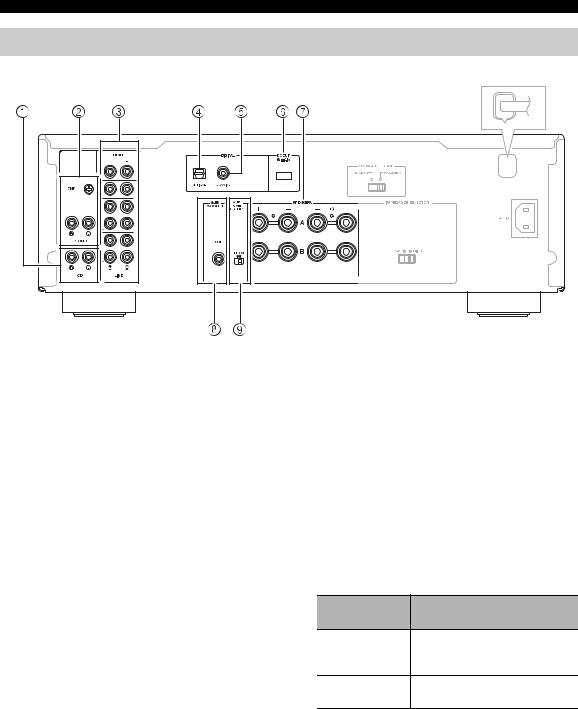
Rear panel
(A-S501/S301)
(A-S701)
1CD input jacks
Used to connect a CD player (see page 9).
2PHONO jacks and GND terminal
Used to connect a turntable that uses an MM cartridge, and to ground the terminal (see page 9).
3Audio input/output jacks
Used to connect external components, such as a tuner, etc (see page 9).
4DIGITAL (OPTICAL) jack
Used to connect a component with a digital optical output (see page 9).
5DIGITAL (COAXIAL) jack
Used to connect a component with a digital coaxial output (see page 9).
6DC OUT jack
For supplying power to a Yamaha AV accessory. For details on connections, refer to the instruction manual of the AV accessory.
7SPEAKERS A/B terminals
Used to connect one or two speaker sets (see page 9).
8SUBWOOFER OUT jack
Used to connect a subwoofer with built-in amplifier (see page 9).
y
The SUBWOOFER OUT jack attenuates signals over 90 Hz.
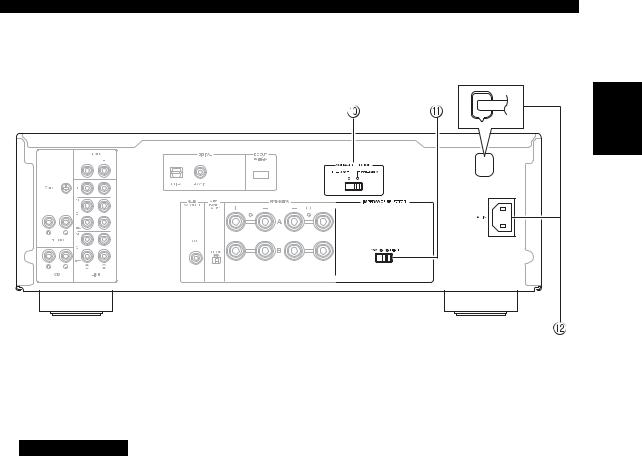
9AUTO POWER STANDBY switch
Switch
Status
position
The unit enters standby mode ON automatically if not operated for 8
hours.
OFF
The unit does not enter standby mode automatically.
4 En
CONTROLS AND FUNCTIONS
(A-S501/S301)
English
(A-S701)
0VOLTAGE SELECTOR (General model only)
Used to set to your local main voltage (see page 10).
A IMPEDANCE SELECTOR switch
CAUTION
Do not change the IMPEDANCE SELECTOR switch while the power is turned on, as doing so may damage the unit.
If the IMPEDANCE SELECTOR switch may not be fully slid to either position, remove the power cable and slide the switch all the way to either position.
Select the switch position according to the impedance of the speakers.
Speaker |
Speaker |
Switch |
|
connection |
impedance |
position |
|
|
|
|
|
SPEAKERS A |
6 Ω or higher |
HIGH |
|
or |
|
|
|
4 Ω or higher |
LOW |
||
SPEAKERS B |
|||
|
|
|
|
SPEAKERS A |
8 Ω or higher |
LOW |
|
and |
|||
SPEAKERS B |
|
|
|
|
|
|
|
Bi-wiring |
6 Ω or higher |
HIGH |
|
|
|
||
4 Ω or higher |
LOW |
||
|
|||
|
|
|
BAC IN (A-S701)
Used to connect the supplied power cable to an AC wall outlet (see page 10).
Power cable (A-S501/S301)
Used to connect this unit to an AC wall outlet (see page 10).
5 En
CONTROLS AND FUNCTIONS
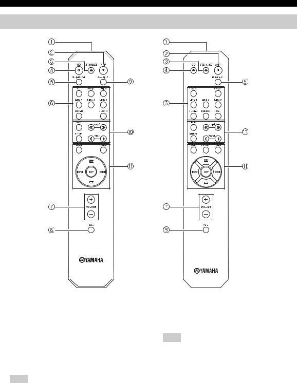
Remote control
(A-S701)
1Infrared signal transmitter
Sends infrared signals.
2AAMP
Turns this unit on, or sets it to standby mode.
3 OPEN/CLOSE
Opens/closes the disc tray of the Yamaha CD player. Refer to the owner’s manual of your CD player for details.
Note
Even when using a Yamaha CD player, certain components and features may not be available.
(A-S501/S301)
4 ACD
Turns the Yamaha CD player on, or sets it to standby mode. Refer to the owner’s manual of your CD player
for details.
Note
Even when using a Yamaha CD player, certain components and features may not be available.
5CD DIRECT AMP (A-S701 only)
Reproduces CD sound in the highest signal quality (see page 12).
6Input selector buttons
Selects the input source you want to listen to.
y
The input source names correspond to the names of the connection jacks on the rear panel.
6 En
|
CONTROLS AND FUNCTIONS |
7 VOLUME +/– |
A Yamaha CD player control buttons |
Increases or decreases the sound output level.
8MUTE
Reduces the current volume level by approximately 20 dB. Press again to restore the audio output to the previous volume level. Pressing the VOLUME +/– also cancels muting.
The input indicator on the front panel for the current input source blinks while the output is muted.
9PURE DIRECT
Reproduces any input source in the purest sound possible (see page 12).
0Yamaha tuner control buttons
The following buttons can be used to control various functions of a Yamaha tuner.
Refer to your component’s owner’s manual for more information.
BAND
Selects the reception band (FM/AM).
The following buttons can be used to control a Yamaha CD player.
Refer to your component’s owner’s manual for more information.
w |
Rewinds playback |
f |
Fast-forwards playback |
DISC SKIP |
Skips to the next disc in a CD changer |
|
(A-S501/S301 only) |
e |
Pauses playback |
b |
Skips backward |
a |
Skips forward |
p |
Starts playback |
s |
Stops playback |
Note
Even when using a Yamaha CD player, certain components and features may not be available.
TUNING jj/ ii
Selects the tuning frequency.
MEMORY
Stores the current FM/AM station as a preset.
PRESET j/ i
Selects a preset FM/AM station.
Note
Even when using a Yamaha tuner, certain components and features may not be available.
English
7 En
CONTROLS AND FUNCTIONS
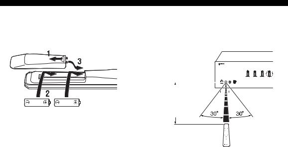
■ Installing batteries |
■ Operation range |
||||||||
|
|
|
|
Point the remote control at the remote control sensor on |
|||||
|
|
|
|
this unit and remain within the operating range shown |
|||||
|
|
|
|
below. |
|||||
|
|
|
|
|
|
|
|
|
|
|
|
|
|
|
|
|
|
|
|
|
|
|
|
|
|
|
|
|
|
|
|
|
|
|
|
|
|
|
|
|
|
|
|
|
|
|
|
|
|
|
|
|
|
|
|
|
|
|
|
|
|
|
|
|
|
|
|
|
|
|
|
|
|
|
|
|
|
|
|
|
Approximately |
|
6 m |
AA, R6, UM-3 batteries |
(20 ft) |
Remote control
■Notes on remote control and batteries
•The area between the remote control and this unit must be clear of large obstacles.
•Be careful not to spill water or other liquids on the remote control.
•Be careful not to drop the remote control.
•Do not leave or store the remote control in the following conditions:
–places of high humidity, such as near a bathroom
–places of high temperatures, such as near a heater or stove
–places of extremely low temperatures
–dusty places
•Change all batteries if you notice the operation range of the remote control narrows.
•If the batteries run out, immediately remove them from the remote control to prevent an explosion or acid leak.
•If you find leaking batteries, discard the batteries immediately, taking care not to touch the leaked material. If the leaked material comes into contact with your skin or gets into your eyes or mouth, rinse it away immediately and consult a doctor. Clean the battery compartment thoroughly before installing new batteries.
•Do not use old batteries together with new ones. This may shorten the life of the new batteries or cause old batteries to leak.
•Do not use different types of batteries (such as alkaline and manganese batteries) together. Batteries that look the same may have a different specification.
•Dispose of batteries according to your regional regulations.
•Keep the batteries in a location out of reach of children.
Batteries can be dangerous if a child were to put in his or her mouth.
•If you plan not to use this unit for a long period of time, remove the batteries from this unit. Otherwise, the batteries will wear out, possibly resulting in a leakage of battery liquid that may damage this unit.
8 En
 Loading...