

Page 1

TECHNICAL MANUAL
TTECHS
Wastewater
Technical Manual
FOR GOULDS WATER TECHNOLOGY, BELL & GOSSETT,
RED JACKET WATER PRODUCTS AND CENTRIPRO
Page 2

Wastewater
Index
FRICTION LOSS
Goulds Water Technology, Bell & Gossett,
Red Jacket Water Products, CentriPro
TERMS AND USABLE FORMULAS
Plastic ........................................................................................ 3
Steel .......................................................................................... 4
Fittings ......................................................................................5
PIPE VOLUME AND VELOCITY
Storage of Water in Various Size Pipes .......................................5
Minimum Flow to Maintain 2 Ft./Sec. .........................................5
SEWAGE PUMP
Sizing and Selection ................................................................... 6
ELECTRICAL DATA
Agency Listing / Removing Plug Letters .................................... 10
Transformer Sizes ..................................................................... 10
Three Phase Unbalance ............................................................11
NEMA Panel Enclosures ...........................................................12
DETERMINING FLOW RATES
Full Pipe Flow ..........................................................................13
Pipe Not Running Full ..............................................................13
Discharge Rate in Gallons per Minute ......................................13
Definitions ............................................................................... 14
Basic Formulas ......................................................................... 14
TYPICAL INSTALLATIONS
Sump ....................................................................................... 16
Effluent and Sewage ................................................................ 17
VARIABLE SPEED DRIVES
Wastewater Pumps ..................................................................18
PANEL LAYOUTS AND WIRING DIAGRAMS
Duplex Single Phase ................................................................20
Duplex Three Phase ................................................................. 22
Simplex Three Phase ................................................................ 24
Simplex Single Phase ............................................................... 25
Switch Diagrams ...................................................................... 27
Sewage Control Panels and Switches .......................................28
PAGE 2
Page 3

Goulds Water Technology, Bell & Gossett,
Wastewater
Friction Loss
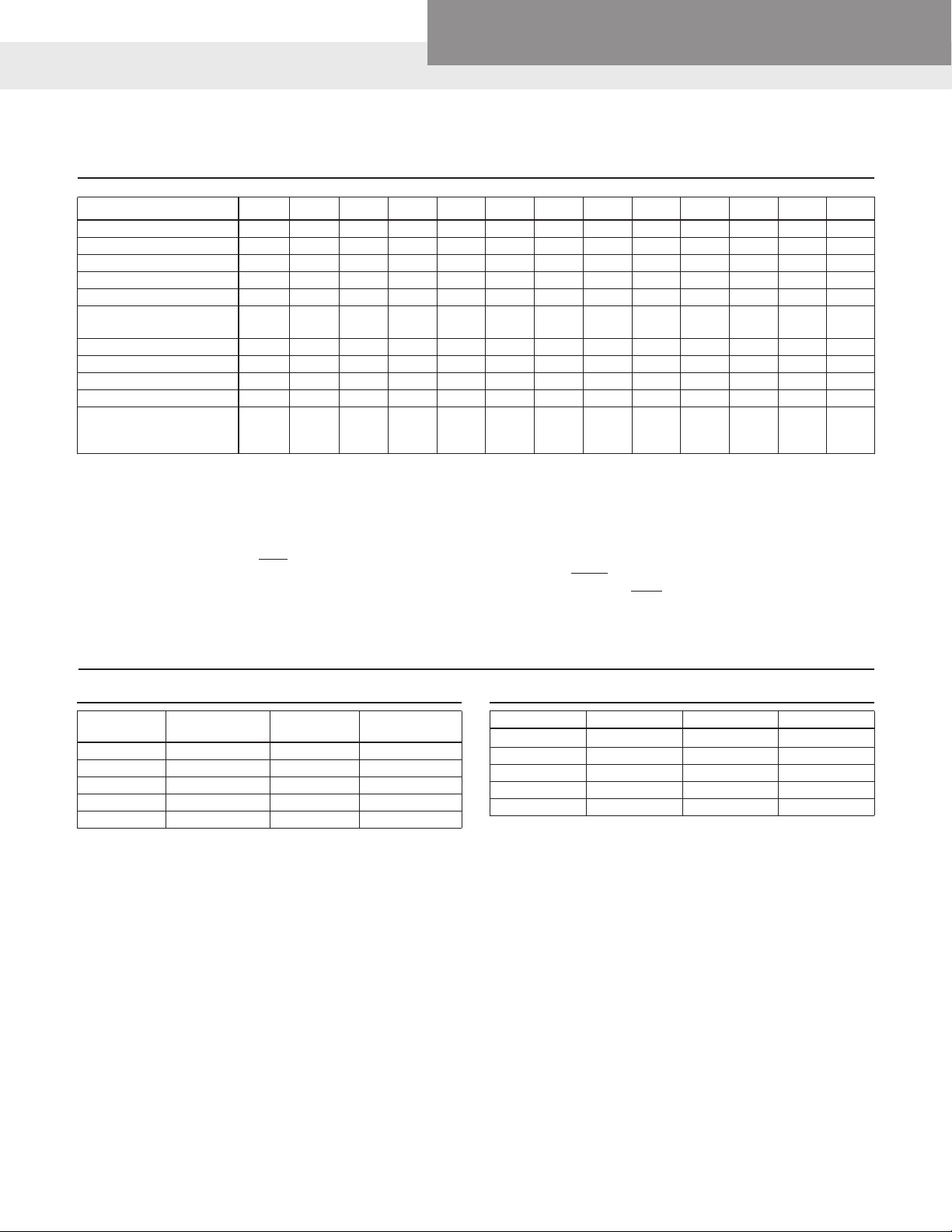
PLASTIC PIPE: FRICTION LOSS (IN FEET OF HEAD) PER 100 FT.
Red Jacket Water Products, CentriPro
GPM GPH
ft. ft. ft. ft. ft. ft. ft. ft. ft. ft. ft. ft. ft.
1 60 4.25 1.38 .356 .11
2 120 15.13 4.83 1.21 .38 .10
3 180 31.97 9.96 2.51 .77 .21 .10
4 240 54.97 17.07 4.21 1.30 .35 .16
5 300 84.41 25.76 6.33 1.92 .51 .24
6 360 36.34 8.83 2.69 .71 .33 .10
8 480 63.71 15.18 4.58 1.19 .55 .17
10 600 97.52 25.98 6.88 1.78 .83 .25 .11
15 900 49.68 14.63 3.75 1.74 .52 .22
20 1,200 86.94 25.07 6.39 2.94 .86 .36 .13
25 1,500 38.41 9.71 4.44 1.29 .54 .19
30 1,800 13.62 6.26 1.81 .75 .26
35 2,100 18.17 8.37 2.42 1.00 .35 .09
40 2,400 23.55 10.70 3.11 1.28 .44 .12
45 2,700 29.44 13.46 3.84 1.54 .55 .15
50 3,000 16.45 4.67 1.93 .66 .17
60 3,600 23.48 6.60 2.71 .93 .25
70 4,200 8.83 3.66 1.24 .33
80 4,800 11.43 4.67 1.58 .41
90 5,400 14.26 5.82 1.98 .52
100 6,000 7.11 2.42 .63 .08
125 7,500 10.83 3.80 .95 .13
150 9,000 5.15 1.33 .18
175 10,500 6.90 1.78 .23
200 12,000 8.90 2.27 .30
250 15,000 3.36 .45 .12
300 18,000 4.85 .63 .17
350 21,000 6.53 .84 .22
400 24,000 1.08 .28
500 30,000 1.66 .42 .14
550 33,000 1.98 .50 .16
600 36,000 2.35 .59 .19
700 42,000 .79 .26
800 48,000 1.02 .33
900 54,000 1.27 .41
950 57,000 .46
1000 60,000 .50
3
⁄8" ½" ¾" 1" 1¼" 1½" 2" 2½" 3" 4" 6" 8" 10"
PAGE 3
Page 4

Goulds Water Technology, Bell & Gossett,
Wastewater
Friction Loss
STEEL PIPE: FRICTION LOSS (IN FEET OF HEAD) PER 100 FT.
Red Jacket Water Products, CentriPro
GPM GPH
ft. ft. ft. ft. ft. ft. ft. ft. ft. ft. ft. ft. ft. ft.
1 60 4.30 1.86 .26
2 120 15.00 4.78 1.21 .38
3 180 31.80 10.00 2.50 .77
4 240 54.90 17.10 4.21 1.30 .34
5 300 83.50 25.80 6.32 1.93 .51 .24
6 360 36.50 8.87 2.68 .70 .33 .10
7 420 48.70 11.80 3.56 .93 .44 .13
8 480 62.70 15.00 4.54 1.18 .56 .17
9 540 18.80 5.65 1.46 .69 .21
10 600 23.00 6.86 1.77 .83 .25 .11 .04
12 720 32.60 9.62 2.48 1.16 .34 .15 .05
15 900 49.70 14.70 3.74 1.75 .52 .22 .08
20 1,200 86.10 25.10 6.34 2.94 .87 .36 .13
25 1,500 38.60 9.65 4.48 1.30 .54 .19
30 1,800 54.60 13.60 6.26 1.82 .75 .26
35 2,100 73.40 18.20 8.37 2.42 1.00 .35
40 2,400 95.00 23.50 10.79 3.10 1.28 .44
45 2,700 30.70 13.45 3.85 1.60 .55
70 4,200 68.80 31.30 8.86 3.63 1.22 .35
100 6,000 62.20 17.40 7.11 2.39 .63
150 9,000 38.00 15.40 5.14 1.32
200 12,000 66.30 26.70 8.90 2.27 .736 .30 .08
250 15,000 90.70 42.80 14.10 3.60 1.20 .49 .13
300 18,000 58.50 19.20 4.89 1.58 .64 .16 .0542
350 21,000 79.20 26.90 6.72 2.18 .88 .23 .0719
400 24,000 103.00 33.90 8.47 2.72 1.09 .279 .0917
450 27,000 130.00 42.75 10.65 3.47 1.36 .348 .114
500 30,000 160.00 52.50 13.00 4.16 1.66 .424 .138
550 33,000 193.00 63.20 15.70 4.98 1.99 .507 .164
600 36,000 230.00 74.80 18.60 5.88 2.34 .597 .192
650 39,000 87.50 21.70 6.87 2.73 .694 .224
700 42,000 101.00 25.00 7.93 3.13 .797 .256
750 45,000 116.00 28.60 9.05 3.57 .907 .291
800 48,000 131.00 32.40 10.22 4.03 1.02 .328
850 51,000 148.00 36.50 11.50 4.53 1.147 .368
900 54,000 165.00 40.80 12.90 5.05 1.27 .410
950 57,000 184.00 45.30 14.30 5.60 1.41 .455
1000 60,000 204.00 50.20 15.80 6.17 1.56 .500
3
⁄8" ½" ¾" 1" 1¼" 1½" 2" 2½" 3" 4" 5" 6" 8" 10"
PAGE 4
Page 5
Goulds Water Technology, Bell & Gossett,
Red Jacket Water Products, CentriPro
Wastewater
Friction Loss
EQUIVALENT NUMBER OF FEET STRAIGHT PIPE FOR DIFFERENT FITTINGS
Size of fittings, Inches ½" ¾" 1" 1¼" 1½" 2" 2 ½" 3" 4" 5" 6" 8" 10"
90° Ell 1.5 2.0 2.7 3.5 4.3 5.5 6.5 8.0 10.0 14.0 15 20 25
45° Ell 0.8 1.0 1.3 1.7 2.0 2.5 3.0 3.8 5.0 6.3 7.1 9.4 12
Long Sweep Ell 1.0 1.4 1.7 2.3 2.7 3.5 4.2 5.2 7.0 9.0 11.0 14.0
Close Return Bend 3.6 5.0 6.0 8.3 10.0 13.0 15.0 18.0 24.0 31.0 37.0 39.0
Tee-Straight Run 1 2 2 3 3 4 5
Tee-Side Inlet or Outlet
or Pitless Adapter
Ball or Globe Valve Open 17.0 22.0 27.0 36.0 43.0 55.0 67.0 82.0 110.0 140.0 160.0 220.0
Angle Valve Open 8.4 12.0 15.0 18.0 22.0 28.0 33.0 42.0 58.0 70.0 83.0 110.0
Gate Valve-Fully Open 0.4 0.5 0.6 0.8 1.0 1.2 1.4 1.7 2.3 2.9 3.5 4.5
Check Valve (Swing) 4 5 7 9 11 13 16 20 26 33 39 52 65
In Line Check Valve
(Spring) 4 6 8 12 14 19 23 32 43 58
or Foot Valve
Example:
(A) 100 ft. of 2" plastic pipe with one (1) 90º elbow and one (1) swing check
valve.
90º elbow – equivalent to 5.5 ft. of straight pipe
Swing check – equivalent to 13.0 f t. of straight pipe
100 ft. of pipe – equivalent to 100 ft. of straight pipe
118.5 ft. = Total equivalent pipe
Figure friction loss for 118.5 ft. of pipe.
3.3 4.5 5.7 7.6 9.0 12.0 14.0 17.0 22.0 27.0 31.0 40.0
(B) Assume flow to be 80 GPM through 2" plastic pipe.
1. Friction loss table shows 11.43 ft. loss per 100 ft. of pipe.
2. In step (A) above we have determined total ft. of pipe to be 118.5 ft.
3. Convert 118.5 ft. to percentage 118.5 ÷ 100 = 1.185
4. Multiply 11.43
x 1.185
13.54455 or 13.5 ft. = Total friction loss in this system.
PIPE VOLUME AND VELOCITY
Storage of Water in Various Size Pipes
Gallons per Foot Gallons per Foot
11⁄4 .06 6 1.4
11⁄2 .09 8 2.6
2 .16 10 4.07
3 .36 12 5.87
4 .652
Pipe Size
Volume in
Pipe Size
Volume in
Minimum Flow to Maintain 2ft./sec. *Scouring Velocity in Various Pipes
Pipe Size Minimum GPM Pipe Size Minimum GPM
11⁄4 9 6 180
11⁄2 13 8 325
2 21 10 500
3 46 12 700
4 80
* Failure to maintain or exceed this velocity will result in clogged pipes.
Based on schedule 40 nominal pipe.
PAGE 5
Page 6
Wastewater
Sewage Pump Selection
VENT SEWER LINE TO UPSTAIRS FIXTURES VENT
SHOWER
TOILET WASHER
Goulds Water Technology, Bell & Gossett,
Red Jacket Water Products, CentriPro
HOUSE SEWER LINE TO STREET
2" PLASTIC PIPE
AND FITTINGS
12'
DRAIN
PIPE
RESIDENTIAL SUBMERSIBLE
EJECTOR SYSTEM
The primary function for which the Submersible Sewage Pump is
designed is the handling of sewage and other fluids containing
unscreened nonabrasive solids and wastes. In order to insure
a maximum of efficiency and dependable performance, careful
selection of pump size is necessary. Required pump capacity will
depend upon the number and type of fixtures discharging into
the sump basin, plus the type of facility served. The fundamentals involved in selecting a pump for a Water System can be
applied to selecting a Submersible Sewage Pump. By answering the three (3) questions concerning capacity, suction, and
discharge conditions we will know what is required of the pump
and be able to select the right pump from the catalog.
1. To simplify the selection of the proper size Submersible Sew-
age Pump, the general rule is to base the pump capacity on
the number of toilets the pump will be serving. This differs
from the selection of the proper pump for a Water System in
that question 1, “Water Needed” is reversed. How much liquid
do we want to dispose of rather than how much do we need?
The following chart will help determine pump capacity:
Sewage Selection Table
for Residential or Commercial Systems
Number of Bathrooms GPM
1 20
2 30
The above selection table takes into consideration other fixtures
which will drain only water into the sewage basin.
Therefore, pump capacity should not be increased for lavatories,
bathtubs, showers, dishwashers, or washing machines. When no
toilets are involved in the facility served, for example, a laundromat, the major fixture discharging waste should be considered.
In this case, the chart should read “Maximum Number of Washing Machines.”
In areas where drain tile from surrounding lawns or fields enters
the sump, groundwater seepage can be determined as follows:
14 GPM for 1,000 sq. ft. of sandy soil
8 GPM for 1,000 sq. ft. of clay soil
If the calculated groundwater seepage is less than one-fourth
of the pump capacity required based on the number of toilets,
the pump capacity should not be increased. Any seepage over
the allowed one-fourth should be added to the required pump
capacity.
2. Since the pump is submerged in the liquid to be pumped,
there is no suction lift. Question 2 does NOT become a factor
in pump selection.
3. Answering Question 3, discharge conditions is the final step
in selecting a Submersible Sewage Pump. Only the vertical distance between the pump and the highest point in the
discharge piping, plus friction losses in discharge pipe and
fittings affect discharge pressure. (Friction losses can be obtained from the friction table in this Selection Manual.)
Normally service pressure is not a consideration. The total of
the vertical distance, plus the friction losses is the required
discharge head in feet.
PAGE 6
Page 7
Goulds Water Technology, Bell & Gossett,
Red Jacket Water Products, CentriPro
Wastewater
Wastewater Pumps Sizing and Selection
WHAT DO YOU NEED TO KNOW TO SELECT A SEWAGE PUMP?
1. Size solids to be handled.
• Efuent (liquid only) – <1"
• Residential – 1½" or larger
• Commercial/Industrial – 2½" or
larger
2. Capacity required.
• 1 bath – 20 GPM
• 2-3 baths – 30 GPM
• 4-5 baths – 45 GPM
3. Pump/Motor Run Time
Units up to 1½ HP should run a
minimum of 1 minute. Two (2) HP and
larger units should run a minimum of
2 minutes.
4. Formula for Total Dynamic Head:
Vertical elevation
+ friction loss (pipe + fittings)
+ Pressure Requirements (x 2.31')
Total head in feet
Note: Wastewater pumps are designed to pump effluent with some
suspended solids, not solids with
some effluent.
5. Must maintain minimum velocity of 2
ft./second (see index).
6. Must turn storage in the discharge
pipe a minimum of one time per
cycle. (See index).
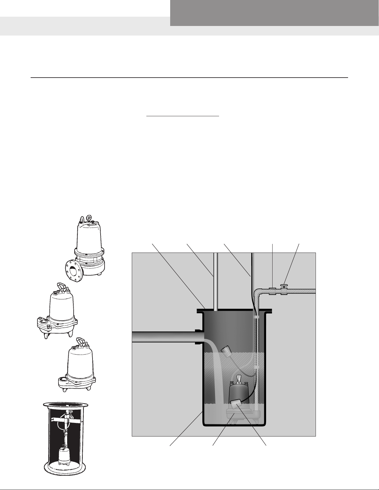
ACCESS
COVER VENT
TO ELECTRICAL CONTROLS OR OUTLET
7. Are receiver basin and cover
required?
8. What is the power available?
• Phase – 1Ø or 3Ø
• Voltage – 115, 200, 230, 460 or
575 V
• Hertz – 50 or 60 Hz
9. What pipe size will be used?
10. Simplex or Duplex System?
(Duplex when service cannot be
interrupted)
Note: State and local codes take
preference.
SWING
CHECK
VALVE
SHUT-OFF
VALVE
INLET
RECEIVER
BASIN
SUBMERSIBLE
WASTEWATER PUMP
DISCHARGE
FLOAT
SWITCH
PAGE 7
Page 8
Wastewater
Flow Rate Calculation
Goulds Water Technology, Bell & Gossett,
Red Jacket Water Products, CentriPro
Residential Sizing
BATHROOM COUNT
Number of Bathrooms Flow Rate per Minute
2 30
3 40
4 50
5 60
6 70
FIXTURE COUNT V = Value style fixture T = Tank Style Fixture
Fixture Type Count
Toilet V 6
Toilet T 3
Lav Sink V or T 1
Tub V or T 2
Shower V or T 2
Full Body Shower Add Flow rate: 9 to 65 Gallons per minute to total
Kitchen Sink V or T 2
Dishwasher V or T 4
Wash Machine V or T 8
Bidet V or T 3
Icemaker V or T 3
Hose Bib V or T 4
Fixture Quantity Count Total Count
Toilets 3 3 9
Tub and Shower 2 4 8
Full body shower 15
Lav Sink 1 3
Kitchen Sink 1 2 2
Dishwasher 1 4 4
Icemaker 1 3 3
Wash Machine 1 8 8
Hose Bib 1 4 4
Total 56
1 20
Commercial Sizing
OCCUPANT SIZING
2000
1500
1000
800
600
400
200
160
120
100
80
60
40
30
20
10
Number of Homes, Trailers, People, etc.
FIXTURE COUNT
Fixture Type Count
Toilet V 10
Toilet T 5
Pedestal Urinal V or T 10
Stall Urinal V or T 5
Lav Sink V or T 3
Kitchen Sink V or T 4
Tub V or T 4
Shower V or T 4
Dishwasher V or T 4
Icemaker V or T 3
Commercial Wash. Machine V or T 6
Hose Bib - Commercial V or T 6
Full Body Shower
Fixture Quantity Count Total Count
Toilet 50 10 500
Lav Sink 50 3 150
Shower 50 4 200
Full body shower 50 15 750
Dishwasher 50 4 200
Icemaker 50 3 150
Wash Machine 10 6 60
Dishwasher 10 4 40
Hose bib 2 6 12
Total 2062
Sewage Selection Chart for Larger Capacity Systems
Office/People
Factory/Employees
School/Students
(B)
(A)
50 100 150 200 250 300 350 400 500 600 700 800 900 1000
Gallons per Minute
Trailer Park/Trailers
Apartments
Motel/Rooms
Homes in Subdivision
Add Flow rate 9 to 65 Gallons per minute to total
PLUMBING WATER SYSTEMS
100
80
1
Fixture Units
PAGE 8
60
40
Demand GPM
20
020406080 100 120 140 160 180 200 220 240
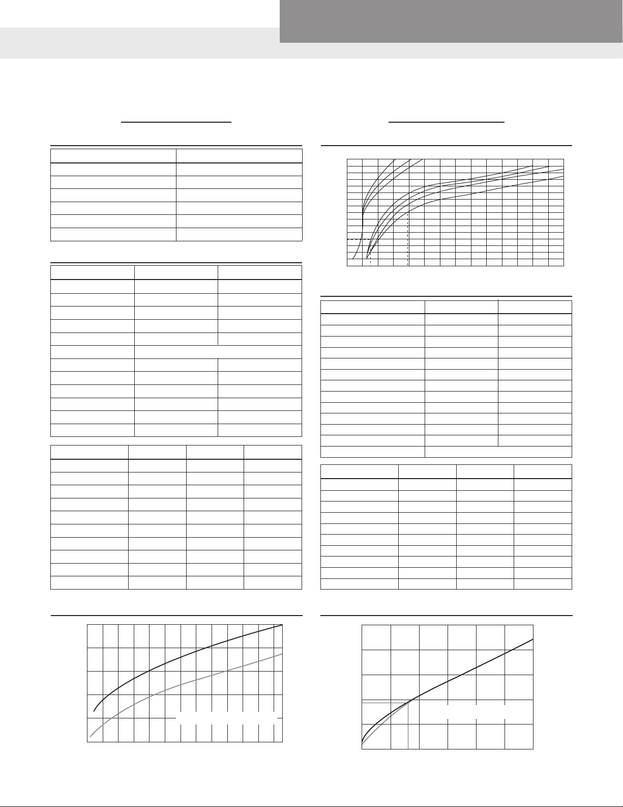
“Hunter” Estimate Curves for Demand Load
1 – Flush Valve Curve 2 – Flush Tank Curve
2
1 – For system predominantly for flush valves
2 – For system predominantly for flush tanks
PLUMBING WATER SYSTEMS
500
400
300
200
180
Demand GPM
1
100
0
2
500 1000
1 – For system predominantly for flush valves
2 – For system predominantly for flush tanks
800
Fixture Units
“Hunter” Estimate Curves for Demand Load
1500 2000 2500 3500
Page 9
Wastewater
Flow Calculation Example
Goulds Water Technology, Bell & Gossett,
Red Jacket Water Products, CentriPro
To Calculate Flow with Fixture Counts
Take total number of each style fixture X Count for that fixture.
Add all fixture total counts. Add Full Body shower flow rate to
total.
Use “Hunter” estimate curves for Demand Load for appropriate
style fixtures. (Valve style fixtures are predominant in Commercial
buildings; Tank style fixtures are predominant in Residential).
COMMERCIAL BUILDING EXAMPLE:
Valve Style Fixtures
25 Toilets
25 Lav sinks
25 Tubs
6 Kitchen Sinks
2 Commercial Washing Machines
1 Dishwasher
Count Calculation
25 Toilets X 10 Count = 250
25 Lav Sinks X 3 Count = 75
25 Tubs X 4 Count = 100
6 Kitchen Sinks X 4 Count = 24
2 Commercial X 6 Count = 12
1 Dishwasher X 4 Count = 4
Total 465 Count
Plumbing Water Systems
500
400
300
200
Demand GPM
1
120
100
2
0
465
500 1000
“Hunter” Estimate Curves for Demand Load
1 – For system predominantly for flush valves
2 – For system predominantly for flush tanks
1500 2000 2500 3500
Fixture Units
Head Calculation
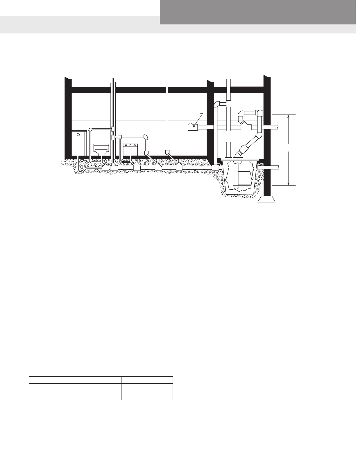
Example: Fig. 1. A two-bathroom home is situated such that
the city sewer main is located above the basement drain facilities. Groundwater seepage through drain tile into the sump is
estimated at 6 GPM. The vertical distance from the pump to the
highest point in the discharge piping is 12 feet.
A pump capable of pumping 30 GPM is required (seepage is
less than one-fourth of the pump capacity so it is automatically
included). The discharge head must be 12 feet, plus any friction
loss in the approximately 15 feet of pipe, 3-90º elbows, 3-45º
elbows, and check valve.
Assume plastic pipe is used.
1. RATE OF FLOW = 30 GPM
Two (2) toilets, includes seepage up to one-fourth of
selected
7.5 GPM allowable so no correction is necessary.
2. SUCTION CONDITIONS – Flooded Suction
3. DISCHARGE CONDITIONS
Vertical Differential 12.0'
Friction losses @ 30 GPM
15' of 2" pipe (1.8' per 100' of pipe) = .2' F.L.
3-2", 90º elbows = 16.5 equivalent feet
3-2", 45º elbows = 7.5 equivalent feet
1-check valve = 19.0 equivalent feet
Total = 43.0 equivalent feet = .6' F.L.
Total Discharge Head = ___________________ 12.8'
Referring to the catalog, we find that a 1/3 HP Sewage Pump
should be adequate for the job.
____
pump capacity. 6 GPM is less than the
Example: The same conditions as in the previous example exist,
except the house is located on a large tract of sandy soil where
the groundwater seepage is estimated @ 20 GPM.
1. RATE OF FLOW = 30 GPM
Two (2) toilets, includes seepage up to one-fourth of
selected pump capacity – 7.5 GPM.
The additional 12.5 GPM (20-7.5) must be added to
the required pump capacity – 12.5 GPM
Total = 42.5 GPM
2. SUCTION CONDITIONS ____________Flooded Suction
3. DISCHARGE CONDITIONS
Vertical Differential – 12.0'
Friction losses @ 42.5 GPM
15' of 2" pipe (3.5' per 100' of pipe) = .5' F.L.
3-2", 90º elbows = 16.5 equivalent feet
3-2", 45º elbows = 7.5 equivalent feet
1-check valve = 19.0 equivalent feet
Total = 43.0 equivalent feet or 1.5' F.L.
Total Discharge Head = 14.0'
Referring again to the catalog, we find that a 1/3 HP
Sewage Pump should be adequate for this installation.
PAGE 9
Page 10

Wastewater
Basin Sizing
CALCULATING BASIN SIZE
Goulds Water Technology, Bell & Gossett,
Red Jacket Water Products, CentriPro
CHART A
1. Choosing Diameter
A minimum of 24" is required for simplex. Duplex stations
normally start at 36", but require much larger for larger diameter discharge pumps.
For example: A pump that flows 100 GPM, requires a 2-minute run time. A duplex station with a diameter of 36" holds
4.4 gallons (see Chart A) per inch.
50 GPM x 2 minutes = 100 gallons
100 gallons / 4.4 gallons per inch 22.72" for pump down.
22.72" would be used for (E).
2. Sizing Depth
Inlet and Float Location Basin Sizing Method
1. Top of basin to bottom of the inlet (A) + in.
2. Inlet to "Alarm" float (B) + in.
3. "Alarm" to "Lag" float (C) + in.
4. "Lag" to "On" float (D) + in.
5. Pump down (E) + 17.86 in.
(Note A)
6. Floor of basin to top of pump case + 19.0 in.
(Note B)
Note A = Minimum suggested basin diameter for duplex configuration is 36".
Volume by inch of basin divided by 2 x's pumping rate.
Note B = Most pumps are approximately 19" tall. Pump should remain covered
during pumping.
Finished Floor
A
B
C
D
Basin
E
19”
Dimensions Volumes
Diameter Depth
Total Gallons
Gallons Per Inch
36 65 1.81
48 84 1.75
72 118 1.64
84 165 1.96
96 188 1.96
36 110 3.00
48 137 2.85
72 199 2.76
84 257 3.05
96 294 3.06
36 159 4.41
48 200 4.17
72 291 4.04
84 370 4.40
96 423 4.40
48 274 5.71
60 339 5.65
42 72 402 5.58
84 504 6.00
96 576 6.00
48 361 7.52
60 446 7.43
48 72 529 7.34
84 658 7.83
96 752 7.83
78 955 12.24
60 84 1028 12.23
96 1175 12.23
78 1375 17.62
72 84 1481 17.63
96 1692 17.63
60 102 1.70
24
60 169 2.82
30
60 246 4.10
36
PAGE 10
Page 11

Wastewater
Electrical Data
AGENCY LISTINGS AND POWER CORD PLUG REMOVAL
Our single-phase sump, effluent and sewage pumps with 115,
208 and 230 volt motors up to and including 1 HP are now
built with NEMA three-prong grounding plug power cords. This
allows qualified electricians or professional pump installers to
easily connect the pumps; according to U.S. National (NEC),
Canadian (CSA), state, provincial and local electrical codes, to a
properly rated piggyback float switch for automatic operation.
NOTICE: This statement is written for the intent purpose of
verifying to electrical inspectors that according to both UL and
CSA standards it is allowable to remove the plug ends for direct
wiring to a disconnect switch, control panel or hard wired float
switch. Removing the plug end does not violate our UL Listing
or CSA/CUS certification in any way. Always follow the aforementioned codes when making connections to the bare leads
once the plug is removed. Plug removal information and wiring
diagrams may be found in the Installation Manual supplied with
the pump and in this booklet. Please use this statement in the
event an inspector needs written assurance of this policy.
Goulds Water Technology, Bell & Gossett,
Red Jacket Water Products, CentriPro
TRANSFORMER SIZES
A full three phase supply is recommended for all three phase
motors, consisting of three individual transformers or one three
phase transformer. “Open” delta or wye connections using only
two transformers can be used, but are more likely to cause problems from current unbalance.
Transformer ratings should be no smaller than listed in the table
for supply power to the motor alone.
TRANSFORMER CAPACITY REQUIRED
FOR SUBMERSIBLE MOTORS
Smallest KVA Rating –
Submersible Total Effective Each Transformer
3Ø Motor
HP Rating Required DELTA 2 DELTA 3
Transformers Transformers
11⁄2 3 2 1
2 4 2 11⁄
3 5 3 2
5 71⁄2 5 3
71⁄2 10 71⁄2 5
10 15 10 5
15 20 15 71⁄
20 25 15 10
25 30 20 10
30 40 25 15
40 50 30 20
50 60 35 20
60 75 40 25
75 90 50 30
100 120 65 40
KVA
Open WYE WYE or
2
2
PAGE 11
Page 12

Goulds Water Technology, Bell & Gossett,
Wastewater
Application – Three Phase Unbalance
THREE PHASE POWER UNBALANCE
Red Jacket Water Products, CentriPro
A full three phase supply is recommended for all three phase
motors, consisting of three individual transformers or one three
phase transformer. So-called “open” delta or wye connections
using only two transformers can be used, but are more likely to
cause problems, such as poor performance overload tripping or
early motor failure due to current unbalance.
Transformer ratings should be no smaller than listed in Table 2
on page 3 for supply power to the motor alone.
Checking and correcting rotation and current unbalance
1. Establish correct motor rotation by running in both directions.
Change rotation by exchanging any two of the three motor
leads. The rotation that gives the most water flow is always
the correct rotation.
2. After correct rotation has been established, check the current
in each of the three motor leads and calculate the current
unbalance as explained in 3 below.
If the current unbalance is 2% or less, leave the leads as connected.
If the current unbalance is more than 2%, current readings
should be checked on each leg using each of the three possible hook-ups. Roll the motor leads across the starter in the
same direction to prevent motor reversal.
3. To calculate percent of current unbalance:
A. Add the three line amp values together.
B. Divide the sum by three, yielding average current.
C. Pick the amp value which is furthest from the average cur-
rent (either high or low).
D. Determine the difference between this amp value (furthest
from average) and the average.
E. Divide the difference by the average.
Multiply the result by 100 to determine percent of
unbalance.
4. Current unbalance should not exceed 5% at service factor load
or 10% at rated input load. If the unbalance cannot be corrected by rolling leads, the source of the unbalance must be
located and corrected. If, on the three possible hookups, the
leg farthest from the average stays on the same power lead,
most of the unbalance is coming from the power source. However, if the reading farthest from average moves with the same
motor lead, the primary source of unbalance is on the “motor
side” of the starter. In this instance, consider a damaged cable,
leaking splice, poor connection, or faulty motor winding.
Phase designation of leads for CCW rotation viewing
shaft end
To reverse rotation, interchange any two leads.
Phase 1 or “A” – Black Motor Lead or T1
Phase 2 or “B” – White Motor Lead or T2
Phase 3 or “C” – Red Motor Lead or T3
Notice: Phase 1, 2 and 3 may not be L1, L2 and L3.
Hookup 1 Hookup 2 Hookup 3
L1 L2 L3 L1 L2 L3 L1 L2 L3
Starter
Terminals
T1 T2 T3 T1 T2 T3 T1 T2 T3
Motor
Leads R B W W R B B W R
T3 T1 T2 T2 T3 T1 T1 T2 T3
Example:
T3-R = 51 amps T2-W = 50 amps T1-B = 50 amps
T1-B = 46 amps T3-R = 48 amps T2-W = 49 amps
T2-W = 53 amps T1-B = 52 amps T3-R = 51 amps
Total = 150 amps Total = 150 amps Total = 150 amps
÷ 3 = 50 amps ÷ 3 = 50 amps ÷ 3 = 50 amps
— 46 = 4 amps — 48 = 2 amps — 49 = 1 amps
4 ÷ 50 = .08 or 8% 2 ÷ 50 = .04 or 4% 1 ÷ 50 = .02 or 2%
OPEN DELTA
FULL THREE
PHASE
FIGURE 12
PAGE 12
Page 13

Goulds Water Technology, Bell & Gossett,
Red Jacket Water Products, CentriPro
Wastewater
Electrical Data
NEMA CONTROL PANEL ENCLOSURES
Enclosure Rating Explanation
NEMA 1 ① To prevent accidental contact with enclosed apparatus. Suitable for application indoors
General Purpose where not exposed to unusual service conditions.
NEMA 2 To prevent accidental contact, and in addition, to exclude falling moisture or dirt.
Driptight
NEMA 3 ① Protection against specied weather hazards. Suitable for use outdoors.
Weatherproof
(Weatherproof Resistant)
NEMA 3R ① Protects against entrance of water from a beating rain. Suitable for general outdoor
Raintight application not requiring sleetproof.
NEMA 4 ① Designed to exclude water applied in form of hose stream. To protect against stream of
Watertight water during cleaning operations, etc.
NEMA 4X ① Designed to exclude water applied in form of hose stream. To protect against stream of
Watertight & Corrosion Resistant water during cleaning operations, etc. Corrosion Resistant.
NEMA 5 Constructed so that dust will not enter enclosed case. Being replaced in some
Dust Tight equipment by NEMA 12.
NEMA 6 Intended to permit enclosed apparatus to be operated successfully when submerged
Submersible in water under specied pressure and time.
NEMA 7 Designed to meet application requirements of National Electrical Code for Class 1,
Hazardous Locations Hazardous Locations (explosive atmospheres). Circuit interruption occurs in air.
Class I – Air Break
NEMA 8 Identical to NEMA 7 above, except the apparatus is immersed in oil.
Hazardous Locations
A, B, C or D
Class II – Oil Immersed
NEMA 9 Designed to meet application requirements of National Electrical Code for Class II
Hazardous Locations Hazardous Locations (combustible dusts, etc.).
E, F or G
Class II
NEMA 10 Meets requirements of U.S. Bureau of Mines. Suitable for use in coal mines.
Bureau of Mines
Permissible
NEMA 11 Provides oil immersion of apparatus such that it is suitable for application where
Dripproof equipment is subject to acid or other corrosive fumes.
Corrosion Resistant
NEMA 12 For use in those industries where it is desired to exclude dust, lint, bers and yings, or
Driptight, Dusttight oil or Industrial coolant seepage.
PAGE 13
Page 14

Goulds Water Technology, Bell & Gossett,
Red Jacket Water Products, CentriPro
Wastewater
Determining Flow Rates
FULL PIPE FLOW – CALCULATION OF DISCHARGE RATE USING HORIZONTAL OPEN DISCHARGE FORMULA
An L-shaped measuring square can be used to estimate flow
capacity, using the chart below. As shown in illustration, place 4"
side of square so that it hangs down and touches the water. The
horizontal distance shown “A” is located in the first column of
the chart and you read across to the pipe diameter (ID) to find
the gallons per minute discharge rate.
Example: A is 8" from a 4" ID pipe
= a discharge rate of 166 GPM.
PIPE NOT RUNNING FULL – CALCULATION OF DISCHARGE RATE USING AREA FACTOR METHOD
D
F
Flow (GPM) = A x D x 1.093 x F
A = Area of pipe in square inches
D = Horizontal distance in inches
F = Effective area factor from chart
Area of pipe equals inside Dia.2 x 0.7854
Example: Pipe inside diameter = 10 in.
12"
D = 20 in.
F = 2½ in.
A = 10 x 10 x 0.7854 = 78.54 square in.
F = 2½
R % =
D 10
F = 0.805
Flow = 78.54 x 20 x 1.039 x 0.805 = 1314 GPM
= 25 %
Ratio Eff. Area Ratio Eff. Area
F/D = R % Factor F F/D = R % Factor F
5 0.981 55 0.436
10 0.948 60 0.373
15 0.905 65 0.312
20 0.858 70 0.253
25 0.805 75 0.195
30 0.747 80 0.142
35 0.688 85 0.095
40 0.627 90 0.052
45 0.564 95 0.019
50 0.500 100 0.000
A
4"
Flow From Horizontal Pipe (Not Full)
DISCHARGE RATE IN GALLONS PER MINUTE/NOMINAL PIPE SIZE (ID)
Horizontal
Dist. (A)
4 5.7 9.8 13.3 22.0 31.3 48.5 83.5
5 7.1 12.2 16.6 27.5 39.0 61.0 104 163
6 8.5 14.7 20.0 33.0 47.0 73.0 125 195 285
7 10.0 17.1 23.2 38.5 55.0 85.0 146 228 334 380
8 11.3 19.6 26.5 44.0 62.5 97.5 166 260 380 665 1060
9 12.8 22.0 29.8 49.5 70.0 110 187 293 430 750 1190 1660
10 14.2 24.5 33.2 55.5 78.2 122 208 326 476 830 1330 1850
11 15.6 27.0 36.5 60.5 86.0 134 229 360 525 915 1460 2100
12 17.0 29.0 40.0 66.0 94.0 146 250 390 570 1000 1600 2220
13 18.5 31.5 43.0 71.5 102 158 270 425 620 1080 1730 2400
14 20.0 34.0 46.5 77.0 109 170 292 456 670 1160 1860 2590
15 21.3 36.3 50.0 82.5 117 183 312 490 710 1250 2000 2780
16 22.7 39.0 53.0 88.0 125 196 334 520 760 1330 2120 2960
17 41.5 56.5 93.0 133 207 355 550 810 1410 2260 3140
18 60.0 99.0 144 220 375 590 860 1500 2390 3330
19 110 148 232 395 620 910 1580 2520 3500
20 156 244 415 650 950 1660 2660 3700
21 256 435 685 1000 1750 2800
22 460 720 1050 1830 2920
23 750 1100 1910 3060
24 1140 2000 3200
Inches
1" 1¼" 1½" 2" 2½" 3" 4" 5" 6" 8" 10" 12"
Pipe Diameter
PAGE 14
Page 15

Wastewater
Terms and Usable Formulas
Goulds Water Technology, Bell & Gossett,
Red Jacket Water Products, CentriPro
The term “head” by itself is
■ Suction Lift: Exists when
rather misleading. It is commonly taken to mean the difference in elevation between
the suction level and the
■ Suction Head: Exists when
discharge level of the liquid
being pumped. Although this
is partially correct, it does not
include all of the conditions
that should be included to give
■ Static Suction Lift:
an accurate description.
■ Friction Head:
The pressure expressed in
lbs./sq. in. or feet of liquid
needed to overcome the
■ Static Suction Head:
resistance to the flow in the
pipe and fittings.
BASIC FORMULAS AND SYMBOLS
the source of supply is
below the center line of the
pump.
the source of supply is
above the center line of the
pump.
The vertical distance from
the center line of the pump
down to the free level of the
liquid source.
The vertical distance from
the center line of the pump
up to the free level of the
liquid source.
■ Static Discharge Head: The
vertical elevation from the
center line of the pump to
the point of free discharge.
■ Dynamic Suction Lift:
Includes static suction lift,
friction head loss and velocity head.
■ Dynamic Suction Head:
Includes static suction head
minus friction head minus
velocity head.
■ Dynamic Discharge Head:
Includes static discharge
head plus friction head plus
velocity head.
■ Total Dynamic Head:
Includes the dynamic
discharge head plus dynamic suction lift or minus
dynamic suction head.
■ Velocity Head: The head
needed to accelerate the
liquid. Knowing the velocity
of the liquid, the velocity
head loss can be calculated
by a simple formula Head =
V2/2g in which g is acceleration due to gravity or 32.16
ft./sec. Although the velocity
head loss is a factor in figuring the dynamic heads, the
value is usually small and in
most cases negligible.
See table.
Formulas
GPM = Lb./Hr.
500 x Sp. Gr.
H = 2.31 x psi
Sp. Gr.
H = 1.134 x In. Hg.
Sp. Gr.
HV = V2 = 0.155 V
2g
V = GPM x 0.321 = GPM x 0.409
A (I.D.)
Symbols
GPM = gallons per minute
Lb. = pounds
Hr. = hour
Sp. Gr. = specific gravity
H = head in feet
psi = pounds per square inch
In. Hg. = inches of mercury
hv = velocity head in feet
V = velocity in feet per second
g = 32.16 ft./sec.2
(acceleration of gravity)
2
2
BHP = GPM x H x Sp. Gr.
3960 x Eff.
Eff. = GPM x H x Sp. Gr.
3960 x BHP
NS = N√GPM
H
H = V
2g
A = area in square inches (πr2)
(for a circle or pipe)
ID = inside diameter in inches
BHP = brake horsepower
Eff. = pump efficiency
expressed as a decimal
NS = specific speed
N = speed in revolutions
per minute
D = impeller in inches
3/4
2
Approximate Cost of Operating Electric Motors
*Average kilowatts input *Av. kw input or cost
Motor or cost based on 1 cent Motor per hr. based on
HP per kilowatt hour HP 1 cent per kw hour
1 Phase 3 Phase 3 Phase
1⁄3 .408 20 16.9
1⁄2 .535 .520 25 20.8
3⁄4 .760 .768 30 26.0
1 1.00 .960 40 33.2
11⁄2 1.50 1.41 50 41.3
2 2.00 1.82 60 49.5
3 2.95 2.70 75 61.5
5 4.65 4.50 100 81.5
71⁄2 6.90 6.75 125 102
10 9.30 9.00
200 162
150 122
PAGE 15
Page 16

Wastewater
Terms and Usable Formulas
BASIC FORMULAS AND SYMBOLS
Goulds Water Technology, Bell & Gossett,
Red Jacket Water Products, CentriPro
Temperature conversion
DEG. C = (DEG. F – 32) x .555
d
DEG. F = (DEG. C x 1.8) + 32
CIRCLE
Water Horsepower = GPM x 8.33 x Head = GPM x Head
33000 3960
Laboratory BHP = Head x GPM x Sp. Gr.
3960 x Eff.
Field BHP = Laboratory BHP + Shaft Loss
Total BHP = Field BHP + Thrust Bearing Loss
Input Horsepower = Total BPH
Motor Eff.
Field Efficiency = Water Horsepower
Total BHP
Overall Plant Efficiency = Water Horsepower
Input Horsepower
Input Horsepower = BHP = 4.826 x K x M x R = 1.732 x E x I x PF
Mot. Eff. T 746
BHP = Brake Horsepower as determined above
Mot. Eff. = Rated Motor Efficiency
K = Power Company Meter Constant
M = Power Company Meter Multiplier, or Ratio of Current and Potential
Transformers connected with meter
Electrical
R = Revolutions of meter disk
T = Time in Sec. for R
E = Voltage per Leg applied to motor
I = Amperes per Leg applied to motor
PF = Power factor of motor
1.732 = Factor for 3-phase motors. This reduces to 1 for single phase motors
Area of a Circle
r
A = area; C = circumference.
A = π r2; π = 3.14
D = diameter
r = radius
C = 2π r
Where:
GPM = Gallons per Minute
8.33 = Pounds of water per gallon
33000 = Ft. Lbs. per minute in one horsepower
Head = Difference in energy head in feet (field head).
Where:
GPM = Gallons per Minute
Head = Lab. Head (including column loss)
Eff. = Lab. Eff. of Pump Bowls
Shaft Loss = HP loss due to mechanical friction of lineshaft bearings
Thrust Bearing Loss = HP Loss in driver thrust bearings
(See (1) below under Misc.)
Motor Eff. from Motor mfg. (as a decimal)
Water HP as determined above
Total BHP as determined above
(See (2) below under Misc.)
Water HP as determined above
Input HP as determined above
Miscellaneous
PAGE 16
Kilowatt input to Motor = .746 x I.H.P. = 1.732 x E x I x PF
1000
(1) Thrust Bearing Loss = .0075 HP per 100 RPM per 1000 lbs. thrust.*
(2) Overall Plant Efficiency sometimes referred to as “Wire to Water” Efficiency
*Thrust (in lbs.) = (thrust constant (k) laboratory head) + (setting in feet x shaft wt. per ft.)
Note: Obtain thrust constant from curve sheets
Discharge Head (in feet of fluid pumped) = Discharge Pressure (psi) x 2.31
Sp. Gr. of Fluid Pumped
KW-Hrs. Per 1000 Gallons of = HD in ft. x 0.00315
Cold Water Pumped Per Hour
Pump Eff. x Mot. Eff.
Page 17

Wastewater
Sump Pump Typical Installations
PUMP ELECTRICAL PLUG
CHECK
VALVE
UNION
PIGGYBACK
SWITCH PLUG
GROUNDED
WALL OUTLET
FLOAT
SWITCH
Goulds Water Technology, Bell & Gossett,
Red Jacket Water Products, CentriPro
1/8''
"RELIEF"
HOLE
PUMPING
RANGE
Suggested Pump Positioning in SumpTypical Pump Installation in Sump
Effluent and Sewage Pumps Typical Installations
Typical Effluent, Sewage
Typical Goulds Effluent, Sewage
and Dewatering Pump Installations
and Dewatering Pump
Installations
PAGE 17
Page 18

Wastewater
Variable Speed Drives
WASTEWATER PUMPS AND VARIABLE SPEED DRIVES
Goulds Water Technology, Bell & Gossett,
Red Jacket Water Products, CentriPro
It is acceptable and increasingly more common to operate threephase wastewater pumps using VFD’s or variable frequency
(speed) drives. We have successfully tested and operated all our
premium cast iron construction, three-phase pumps between 30
and 60 hertz operation. The pumps should never be operated
below 30 hertz (the VFD must be programmed for a minimum
speed of 30 hertz to prevent continuous operation) or above 60
hertz due to increased motor HP loading, higher amperage and
the resultant heat rise (see HP in 70 hertz Performance Multipliers).
The “Affinity Laws” state that for a given pump, the capacity will
vary directly with a change in speed, the head will vary as the
square of the speed change and the required power will vary as
the cube of the speed change. (The Affinity Law formulas can be
found in the Water Products Technical Manual, TTECHWP). The
Performance Multiplier Chart provides shortcut multipliers that
eliminate having to solve the Affinity Law equations.
To calculate a pump’s total performance range when using a
VFD, use the 30 hertz data to create a minimum speed curve, the
VFD controlled pump should always be operated between 30
hertz and the published 60 hertz curve. Where it operates at any
given moment is irrelevant.
Q1, H1 and BHP1 are determined at the pump’s rated speed
N1 (rpm).
Q2, H2 and BHP2 are determined at speed N2 (rpm).
Hertz Performance Multipliers
70 – Q2 = Q1 x 1.17 H2 = H1 x 1.37 BHP2 = BHP1 x 1.6
60 – Use the standard published curve data
50 – Q2 = Q1 x .83 H
40 – Q2 = Q1 x .67 H2 = H1 x .45 BHP2 = BHP1 x .3
30 – Q2 = Q1 x .5 H2 = H1 x .25 BHP2 = BHP1 x .125
An example would be, solve for Q2, H2 and BHP2 for a 60 Hz
pump that produces 100 gpm (Q1) @ 100’ tdh (H1) using 5 hp
(BHP1) when it is operated at 30 Hz :
Answers: 100 gpm x .5 = 50 gpm, 100’ TDH x .25 = 25’ TDH
and 5 hp x .125 = .63 hp.
VFD’s save energy while reducing the thrust on the motor bearings and the starting torque on the shaft and impeller.
Contact Customer Service for details, pricing and availability of
our full line of VFD products.
= H1 x .69 BHP2 = BHP1 x .57
2
Use the multipliers with a minimum of 3 data points taken from
any standard, 60 Hz curve to determine the performance of that
pump at a new speed.
PAGE 18
Page 19

Goulds Water Technology, Bell & Gossett,
Wastewater
Standard Panel Selection Check List
Red Jacket Water Products, CentriPro
PANEL SIZING
Pump Model Chosen:
1. Phase: Single
2. Amp draw of pump:
3. Simplex (“1” Pump)
4. Does pump have a seal fail circuit: yes or no
(NOTE: If Question 4 is yes, add a seal fail option as noted.)
__________________
_____
Three
____________
_____
Duplex (“2” Pumps in Pit)
_____
(found on bulletin)
_____
(see note)
If Question 1. Single 3. Simplex use Chart A
If Question 1. Three 3. Simplex use Chart B
If Question 1. Single 3. Duplex use Chart C
If Question 1. Three 3. Duplex use Chart D
CHART A
Panel Part Number
Maximum HP
Amp/
Enclosure
S10020N1 (non-modifiable) up to 20 Indoor
S10020 up to 20
Outdoor
S12127 21-27
Outdoor
S12836 28-36
Outdoor
S1GD2 (includes caps for
1GD,12GDS after 12/2005)
Outdoor
S1GGC2 (includes caps for
1GD,12GDS before 12/2005)
Outdoor
S1FGC2
(use with1GA/15GDS)
Outdoor
S1FGC3
(use with1/2GA/15/20GDS)
Outdoor
S1FGC5
(use with 2GA /20GDS)
Add option H for seal fail circuit to all of the above except S10020N1. Except for GA/
GDS grinder pumps, seal fail and high temperature are included in panel.
Outdoor
Indoor/
Indoor/
Indoor/
Indoor/
2 HP
Indoor/
2 HP
Indoor/
2 HP
Indoor/
3 HP
Indoor/
5 HP
NOTE: Not all models are listed. For more assistance,
contact customer service.
CHART B
Panel Part Number
Maximum HP
Amp/
Enclosure
S31625 1.6-2.5 Indoor/Outdoor
S32540 2.5-4.0 Indoor/Outdoor
S34063 4.0-6.3 Indoor/Outdoor
S36310 6.3-10 Indoor/Outdoor
S31016 10-16 Indoor/Outdoor
S31620 16-20 Indoor/Outdoor
S32025 20-25 Indoor/Outdoor
S32232 22-32 Indoor/Outdoor
Add option H for seal fail circuit to all of the above, unless using a GA/GDS pump, use
an “O” option.
CHART C
Panel Part Number
Maximum HP
D10020N1 up to 20 Indoor
D10020 up to 20
Outdoor
D12127 21-27
Outdoor
D12836 28-36
Outdoor
D1GD2 (includes caps for
1GD,12GDS after 12/2005)
D1GGC2 (includes caps for
1GD,12GDS before 12/2005)
D1FGC2
(use with 1GA / 15GDS)
D1FGC3
(use with 1/2GA / 15/20GDS)
D1FGC5
(use with 2GA / 20GDS)
Add option J for seal fail circuit to all of the above except D10020N1. Do not add seal
fail for GA/GDS grinder pumps, seal fail and high temperature are included in panel.
Amp/
Indoor/
Indoor/
Indoor/
Indoor/
Outdoor
Outdoor
Outdoor
Outdoor
Outdoor
2 HP
Indoor/
2 HP
Indoor/
2 HP
Indoor/
3 HP
Indoor/
5 HP
CHART D
Panel Part Number
Maximum HP
Amp/
Enclosure
D31625 1.6-2.5 Indoor/Outdoor
D32540 2.5-4.0 Indoor/Outdoor
D34063 4.0-6.3 Indoor/Outdoor
D36310 6.3-10 Indoor/Outdoor
D31016 10-16 Indoor/Outdoor
D31620 16-20 Indoor/Outdoor
D32025 20-25 Indoor/Outdoor
D32232 22-32 Indoor/Outdoor
Add option J for seal fail circuit to all of the above except for GA/GDS pumps, use an
Option “P”. For other panel options see catalog for adders. For adders not found in
the catalog, or more than three options a specification is needed for the Customer
Service Department to prepare a quotation. Use of the Custom panel selection sheet
is advised with more than three options.
Enclosure
PAGE 19
Page 20

Goulds Water Technology, Bell & Gossett,
Red Jacket Water Products, CentriPro
Wastewater
Duplex Single Phase Wiring Diagram – D10020
NOTE: The standard panels shown in this book are not designed to be used with pumps requiring external capacitors.
See the catalog for panels with built-in capacitor packs.
FOR 120 VOLT OPERATION
USE TERMINALS (L1) AND (N)
JUMP TERMINALS (N) AND (L2)
230 VAC
SINGLE PHASE
60 Hz
A 230 VOLT SYSTEM
REQUIRES A 4 WIRE
POWER SUPPLY LINE
N AND GND.
L1, L2,
WITHOUT A
NEUTRAL
THE CONTROL CIRCUIT
WILL NOT WORK.
ALTERNATOR SWITCH –
STANDARD ON ALL DUPLEX
PANELS, THIS SWITCH PROVIDES
OPTIONS FOR: ALTERNATE
PUMPS, USE ONLY PUMP 1 OR
USE ONLY PUMP 2. IT IS USED
WHEN A PUMP IS REMOVED
FOR SERVICE.
➀ FOR SEPARATE 120 VAC
CONTROL POWER SUPPLY,
REMOVE JUMPER (J1) FROM
TERMINALS (H) AND (L1).
CONNECT 15 AMP MAX.
PROTECTED 120 VAC SUPPLY
TO TERMINALS (L1) AND (N).
WITH THE NEUTRAL OF THE
SUPPLY TO (N).
➁ FOR USE WITH WIDE ANGLE
FLOAT SWITCH (ONE FLOAT FOR
BOTH ON AND OFF OPERATION).
JUMP TERMINALS (3) AND (4),
INSTALL WIDE ANGLE FLOAT TO
TERMINALS (1) AND (2).
③ FACTORY WIRED FOR (3) FLOAT
OPERATION. FOR (4) FLOAT
OPERATION, REMOVE JUMPER (J2)
FROM TERMNALS (6) AND (8). INSTALL
LAG FLOAT ON
TERMINALS (5) AND (6).
PAGE 20
GND
25 A
25 A
L1
L2
N
CONTROL
ON-OFF
BLACK
YELLOW
BLACK
ORANGE
ALTERNATOR SWITCH
R1
R2
BLACK
J1➀
C
L1 N
H
L1
OFF LEAD LAGALARM
N 12345678910 11
OFF FLOAT➁
S1
S2
PUMP 1
ALT
PUMP 2
LEAD FLOAT
LAG FLOAT
(OPTIONAL)③
ALARM FLOAT
1
1T
2
1
2T
2
HAND
OFF
AUTO
HAND
OFF
AUTO
TEST
MUTE
RESET
FLASHING
SONALERT
DRY CONTACTS
J2
PURPLE
BLUE
RED
RED
SILENCE
YEL
YELLOW
BRW
BROWN
RED
PINK
WHITE
PUMP NO. 1
PUMP NO. 2
WHITE
RUN
S1
RUN
S2
TEST
RESET
FLASH
HORN
Page 21

Goulds Water Technology, Bell & Gossett,
Red Jacket Water Products, CentriPro
Wastewater
Duplex Single Phase Panel Layout – D10020
CB1 CB2
S1 S2
CONTROL PUMP 1 PUMP 2
ON
OFF
ALTERNATOR SWITCH –
STANDARD ON ALL DUPLEX
PANELS, THIS SWITCH PROVIDES
OPTIONS FOR: ALTERNATE
PUMPS, USE ONLY PUMP 1 OR
USE ONLY PUMP 2. IT IS USED
WHEN A PUMP IS REMOVED
FOR SERVICE.
AUTO
OFF
HAND
➀ FOR SEPARATE 120 VAC
CONTROL POWER SUPPLY,
REMOVE JUMPER (J1) FROM
TERMINALS (H) AND (L1).
CONNECT 15 AMP MAX.
PROTECTED 120 VAC SUPPLY
TO TERMINALS (L1) AND (N).
WITH THE NEUTRAL OF THE
SUPPLY TO (N).
➁ FOR 120 VAC OPERATION,
USE TERMINALS L1 AND N,
JUMP TERMINALS L2 AND N.
③ FACTORY WIRED FOR (3) FLOAT
OPERATION. FOR (4) FLOAT
OPERATION, REMOVE JUMPER (J2)
FROM TERMINALS (6) AND (8).
INSTALL LAG FLOAT ON
TERMINALS (5) AND (6).
120/230 VAC ➁
SINGLE PHASE
60 Hz
L1 L2 N
1212
1T 2T
PUMP
NO. 1
PUMP
NO. 2
R1
R2
C
L1
HL1N 1234
J1➀
ALTERNATOR SWITCH
PUMP 1
ALT
PUMP 2
OFF
N
LEAD FLOAT
OFF FLOAT
LEAD LAGALARM
5678910
ALARM FLOAT
LAG FLOAT
(OPTIONAL)③
TEST
MUTE
RESET
FLASHING
SONALERT
11
DRY CONTACTS
J2
NOTE: Panel is not to be used with
pumps that do not include capacitors.
PAGE 21
Page 22

Goulds Water Technology, Bell & Gossett,
Red Jacket Water Products, CentriPro
Wastewater
Duplex Three Phase Wiring Diagram – D3 — — — —
S1
S2
208/230/460/575 VAC
THREE PHASE
60 Hz
L1
L2
L3
1
1
2
T
3
1
2
2
T
3
PUMP
NO. 1
PUMP
NO. 2
ALTERNATOR SWITCH –
STANDARD ON ALL DUPLEX
PANELS, THIS SWITCH PROVIDES
OPTIONS FOR: ALTERNATE
PUMPS, USE ONLY PUMP 1 OR
USE ONLY PUMP 2. IT IS USED
WHEN A PUMP IS REMOVED
FOR SERVICE.
➀ FOR SEPARATE 120 VAC
CONTROL POWER SUPPLY,
REMOVE JUMPER (J1) FROM
TERMINALS (H) AND (L1).
CONNECT 15 AMP MAX.
PROTECTED 120 VAC SUPPLY
TO TERMINALS (L1) AND (N).
WITH THE NEUTRAL OF THE
SUPPLY TO (N).
➁ FOR USE WITH WIDE ANGLE
FLOAT SWITCH (ONE FLOAT FOR
BOTH ON AND OFF OPERATION).
JUMP TERMINALS (3) AND (4),
INSTALL WIDE ANGLE FLOAT TO
TERMINALS (1) AND (2).
③ FACTORY WIRED FOR (3) FLOAT
OPERATION. FOR (4) FLOAT
OPERATION, REMOVE JUMPER (J2)
FROM TERMNALS (6) AND (8).
INSTALL LAG FLOAT ON
TERMINALS (5) AND (6).
2 A
CONTROL
ON-OFF
BLACK
BLACK
BLACK
J1➀
575 VAC
460 VAC
75 VA
120 VAC
YELLOW
R1
R2
C
L1 N
H
L1
FACTORY WIRED FOR 460 VAC. FOR 208, 230 OR
230 VAC
208 VAC
FOR 575 VAC OPERATION CHANGE CONTROL TRANSFORMER
PRIMARY AT TERMINAL BLOCK.
HAND
OFF
AUTO
HAND
OFF
ORANGE
ALTERNATOR SWITCH
PUMP 1
ALT
PUMP 2
OFF LEAD LAGALARM
N 12345678910 11
DRY CONTACTS
ALARM FLOAT
AUTO
TEST
MUTE
RESET
FLASHING
SONALERT
J2
PURPLE
BLUE
RED
RED
SILENCE
YEL
YELLOW
BRW
BROWN
RED
PINK
WHITE
WHITE
RUN
S1
RUN
S2
TEST
RESET
FLASH
HORN
PAGE 22
OFF FLOAT➁
LEAD FLOAT
LAG FLOAT
(OPTIONAL)③
Page 23

Goulds Water Technology, Bell & Gossett,
Red Jacket Water Products, CentriPro
Wastewater
Duplex Three Phase Panel Layout – D3 — — — —
➀ FOR SEPARATE 120 VAC
CONTROL POWER SUPPLY,
REMOVE JUMPER (J1) FROM
TERMINALS (H) AND (L1).
CONNECT 15 AMP MAX.
PROTECTED 120 VAC SUPPLY
TO TERMINALS (L1) AND (N).
WITH THE NEUTRAL OF THE
SUPPLY TO (N).
③ FACTORY WIRED FOR (3) FLOAT
OPERATION. FOR (4) FLOAT
OPERATION, REMOVE JUMPER (J2)
FROM TERMINALS (6) AND (8).
INSTALL LAG FLOAT ON
TERMINALS (5) AND (6).
CB1 CB2
S1 S1
L1 L2
L3
1T1
1T2 1T3 2T1 2T2 2T3
CONTROL PUMP 1PUMP 2
ON
OFF
AUTO
OFF
HAND
TERMINAL BLOCK
208
230
460
575
FACTORY WIRED FOR 460 VAC. FOR 208,230 OR
575 VAC OPERATION, CHANGE CONTROL TRANSFORMER
PRIMARY AT TERMINAL BLOCK.
ALTERNATOR SWITCH – STANDARD
ON ALL DUPLEX PANELS, THIS SWITCH
PROVIDES OPTIONS FOR: ALTERNATE
PUMPS, USE ONLY PUMP 1 OR USE
ONLY PUMP 2. IT IS USED WHEN A
PUMP IS REMOVED FOR SERVICE.
R1
R2
C
L1
HL1N 1234
J1➀
ALTERNATOR SWITCH
PUMP 1
ALT
PUMP 2
OFF
LEAD
N
2 A
TRANSFORMER
ALARMLAG
5678910
DRY CONTACTS
TEST
MUTE
RESET
FLASHING
SONALERT
11
J2
208/230/460/575 VAC
THREE PHASE
60 Hz
PUMP
NO. 1
PUMP
NO. 2
OFF FLOAT
LEAD FLOAT
LAG FLOAT
(OPTIONAL)③
ALARM FLOAT
PAGE 23
Page 24

Goulds Water Technology, Bell & Gossett,
JUMP TERMINALS (3) AND (4), INSTALL WIDE ANGLE FLOAT TO TERMINALS (1) AND (2).
Red Jacket Water Products, CentriPro
Wastewater
Simplex Three Phase Panel Layout
NOTE: A fused disconnect or circuit breaker must be provided by installer. Provide disconnect sizing per NEC 430-53(C).
S1
L1
L2
L3
1.4 A
PUMP
1 A
CONTROL
ON-OFF
BLACK
FLASH
100 VA
BROWN
RED
WHT
575
120 VAC
R1
C
L1
FLASHING
460
FACTORY WIRED FOR 460 VAC. FOR 208, 230 OR
230
208
FOR 575 VAC OPERATION CHANGE CONTROL TRANSFORMER
PRIMARY AT TERMINAL BLOCK.
HAND
OFF
PURPLE
AUTO
ON
OFF
ALARM
RESET
MUTE
TEST
YEL
YELLOW
RED
RED
RUN
S1
SILENCE
TEST
WHT
HORN
PINK
BLACK
FOR SEPARATE 120 VAC
CONTROL POWER SUPPLY,
REMOVE JUMPER (J1) FROM
TERMINALS (H) AND (L1).
CONNECT 15 AMP MAX.
PROTECTED 120 VAC SUPPLY
TO TERMINALS (L1) AND (N).
WITH THE NEUTRAL OF THE
SUPPLY TO (N).
FOR USE WITH WIDE ANGLE FLOAT SWITCH (ONE FLOAT FOR BOTH ON AND OFF OPERATION).
PAGE 24
J1
SONALERT
H
L1
NEU
N1 2345678
OFF FLOAT
WHITE
DRY CONTACTS
ALARM FLOAT
ON FLOAT
Page 25

Goulds Water Technology, Bell & Gossett,
Red Jacket Water Products, CentriPro
Wastewater
Simplex Single Phase Wiring Diagram – S10020 Before October 1, 2003
NOTE: The standard panels shown in this book are not designed to be used with pumps requiring external capacitors.
See the catalog for panels with built-in capacitor packs.
115/230 VAC (FOR 115 VAC, USE TERMINALS L1 AND N, JUMP L2 AND N).
SINGLE PHASE, 60 Hz
L1
L2
N
S1
T1
T2
PUMP
A 230 VOLT SYSTEM
REQUIRES A 4 WIRE
POWER SUPPLY LINE
L1, L2,
N AND GND.
WITHOUT A
NEUTRAL THE
CONTROL CIRCUIT
WILL NOT WORK.
GND
LL1
J1
NOTE: WHEN USING SEPARATE 115 VAC CONTROL POWER SUPPLY, REMOVE
JUMPER (J1) FROM TERMINALS (L1) AND LL1). CONNECT 15 AMP MAX.
PROTECTED 115 VAC SUPPLY TO TERMINALS (LL1) AND (N) WITH
THE NEUTRAL OF THE SUPPLY TO (N).
CONTROL
ON-OFF
123
OFF FLOATON FLOAT
4
ALARM FLOAT
TEST
S1-AUX
HAND
OFF
AUTO
HORN *
ON - OFF
RUN
S1
HIGH LEVEL
HORN
*NOTE: THE HORN ON/OFF SELECTOR SWITCH MUST BE PLACED
BACK INTO THE (ON) POSITION AFTER THE ALARM
CONDITION HAS BEEN CORRECTED IN ORDER TO
MAINTAIN THE AUDIO ALARM ANNUNCIATION
PAGE 25
Page 26

Goulds Water Technology, Bell & Gossett,
Red Jacket Water Products, CentriPro
Wastewater
Simplex Single Phase Wiring Diagram – S10020 After October 1, 2003
115/230 VAC (FOR 115 VAC, USE TERMINALS L1 AND N, JUMP L2 AND N.)
PROVIDE DISCONNECT AND
BRANCH CIRCUIT PROTECTION
PER NEC CODE
L1
L2
SINGLE PHASE 60 HZ
S1
T1
PUMP
T2
N
GND
CONTROL
ON-OFF
BLACK
FLASH
BROWN
RED
WHT
R1
C
L1
FLASHING
ON
OFF
ALARM
HAND
OFF
AUTO
RESET
MUTE
TEST
PURPLE
WHITE
RUN
S1
SILENCE
YEL
YELLOW
TEST
RED
RED
PAGE 26
WHT
HORN
PINK
BLACK
FOR SEPARATE 120 VAC
CONTROL POWER SUPPLY,
REMOVE JUMPER (J1) FROM
TERMINALS (H) AND (L1).
CONNECT 15 AMP MAX.
PROTECTED 120 VAC SUPPLY
TO TERMINALS (L1) AND (N).
WITH THE NEUTRAL OF THE
SUPPLY TO (N).
FOR USE WITH WIDE ANGLE FLOAT SWITCH (ONE FLOAT FOR BOTH ON AND OFF OPERATION).
JUMP TERMINALS (3) AND (4), INSTALL WIDE ANGLE FLOAT TO TERMINALS (1) AND (2).
J1
SONALERT
H
L1
NEU
N1 2345678
DRY CONTACTS
ALARM FLOAT
ON FLOAT
OFF FLOAT
WHITE
Page 27

Wastewater
Switch Diagrams
Goulds Water Technology, Bell & Gossett,
Red Jacket Water Products, CentriPro
PAGE 27
Page 28

Goulds Water Technology, Bell & Gossett,
Red Jacket Water Products, CentriPro
Wastewater
Sewage Control Panels and Switches
There are two basic switches used in sewage and effluent systems. Single-action or narrow-angle float switches perform one function
(on or off). They operate over a range of 15º. Wide-angle, or double-action float and diaphragm switches perform two functions (on
and
off). Wide-angle float switches operate over a 90º range and diaphragm switches on a 6” rise in water level.
Control panel wiring diagrams refer to 3 float and 4 float systems, this terminology refers to the use of single-action switches. The following chart shows how many of either type switch to use with different control panels.
Duplex Control Panels
Typical Duplex panels use the following switch set-ups depending on the switch type you use. Most Duplex control panels have a standard high level alarm circuit with a flashing light, most have a horn or bell. Once it turns On - the alarm must be manually reset (turned
off) on Duplex panels.
Using a Single-action or Narrow-angle Switch requires:
Three Float Panel Wiring Four Float Panel Wiring
#1 Bottom Pumps Off #1 Bottom Pumps Off
#2 Middle 1st Pump On #2 2nd 1st Pump On
#3 Top 2nd Pump & Alarm On #3 3rd 2nd Pump On
#4 Top Alarm On
Using Double-Action or Wide-Angle Switches; A2D23W, A2E21, A2E22, A2E23,
A2D11, A2D31 or A2S23 requires:
Three Float Panel Wiring Four Float Panel Wiring
#1 Bottom 1st Pump On/Both Off #1 Bottom 1st Pump On/Both Off
#2 Top 2nd Pump and Alarm On #2 Middle 2nd Pump On
#3 Top Alarm On
Simplex Control Panels
Only some Simplex panels have alarms. This is why the switch quantity requirements vary by simplex panel model.
All of our SES panels have high level alarms.
Using a Single-action or Narrow-angle Switch requires:
Simplex Panel with Alarm Simplex Panel with No Alarm
#1 Bottom Pump Off #1 Bottom Pump Off
#2 Middle Pump On #2 Top Pump On
#3 Top Alarm On/Off
Using Double-Action or Wide-angle Switches requires:
Simplex Panel with Alarm Simplex Panel with No Alarm
#1 Bottom Pump On/Off #1 Bottom Pump On/Off
#2 Top Alarm On/Off
NOTE: 1st pump may also be referred to as “Lead” pump,
2nd pump may be called “Lag” pump.
PAGE 28
Page 29

Goulds Water Technology, Bell & Gossett,
Red Jacket Water Products, CentriPro
Wastewater
We sell and stock a complete line of wastewater float switches. The
most up-to-date information is found in the wastewater catalog
Electrical Section. The switch bulletin is coded as BCPFS, i.e. Bulletin
CentriPro Float Switches.
It may be found on our websites:
www.xyleminc.com/brands/gouldswatertechnology
www.xyleminc.com/brands/redjacketwaterproducts
www.xyleminc.com/brands/bellgossett
www.xyleminc.com/brands/centripro
PAGE 29
Page 30

Wastewater
Notes
Goulds Water Technology, Bell & Gossett,
Red Jacket Water Products, CentriPro
PAGE 30
Page 31

Wastewater
Notes
Goulds Water Technology, Bell & Gossett,
Red Jacket Water Products, CentriPro
PAGE 31
Page 32

Xylem
1) The tissue in plants that brings water upward from the roots;
2) a leading global water technology company.
We’re 12,000 people unified in a common purpose: creating innovative solutions
to meet our world’s water needs. Developing new technologies that will improve
the way water is used, conserved, and re-used in the future is central to our work.
We move, treat, analyze, and return water to the environment, and we help people
use water efficiently, in their homes, buildings, factories and farms. In more than
150 countries, we have strong, long-standing relationships with customers who
know us for our powerful combination of leading product brands and applications
expertise, backed by a legacy of innovation.
For more information on how Xylem can help you, go to www.xyleminc.com
Xylem, Inc.
2881 East Bayard Street Ext., Suite A
Seneca Falls, NY 13148
Phone: (866) 325-4210
Fax: (888) 322-5877
www.xyleminc.com
Goulds is a registered trademark of Goulds Pumps, Inc. and is used under license.
Bell & Gossett, Red Jacket Water Products and CentriPro are trademarks of Xylem
Inc. or one of its subsidiaries.
© 2011 Xylem Inc. TTECHS R4 November 2011
 Loading...