

Page 1
Page 2
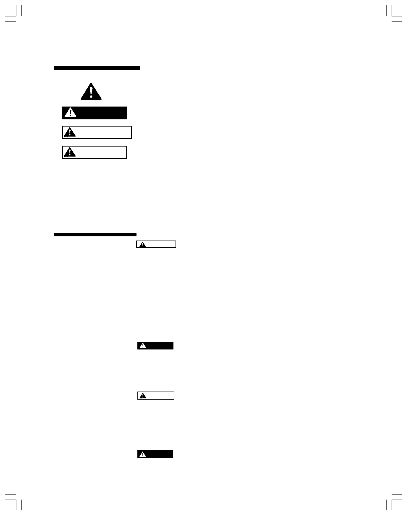
Read and Follow
Safety Instructions!
DANGER
WARNING
CAUTION
This is the safety-alert symbol. When you see this symbol on your system or in this
manual, look for one of the following signal words and be alert to the potential for
personal injury;
DANGER warns about hazards that will cause serious personal injury, death or
major property damage if ignored.
WARNING warns about hazards that could cause serious personal injury, death or
major property damage if ignored.
CAUTION warns about hazards that may result in minor or moderate injury or
property damage if ignored.
This label NOTICE indicates special instructions which are important but not related
to hazards.
Carefully read and follow all safety instructions in this manual or on system.
Keep safety labels in good condition.
Replace missing or damaged safety labels.
Safety Instructions
1. WARNING - THESE WATER TANKS ARE DESIGNED FOR
2. It is your responsibility to make sure your installation meets all national and
3.
4. If a captive air water systems tank replaces a standard galvanized tank on a
5.
OPERATION ON AMBIENT TEMPERATURE WATER SYSTEMS LIMITED
TO A MAXIMUM WORKING PRESSURE OF 125 POUNDS PER SQUARE INCH
GAUGE (PSIG). IF YOUR SYSTEM HAS THE ABILITY TO EXCEED 125 PSIG
WORKING PRESSURE (100 PSIG IF THIS IS A PUMP MOUNTED UNIT), A
SUITABLE SAFETY DEVICE MUST BE INSTALLED. THIS CAN BE EITHER A
HIGH PRESSURE ELECTRICAL CUT-OFF SWITCH AND/OR A PRESSURE
RELIEF VALVE. FAILURE TO FOLLOW THESE INSTRUCTIONS CAN CAUSE
TANK RUPTURE AND RESULT IN PERSONAL INJURY AND/OR PROPERTY
DAMAGE.
local plumbing and electrical codes.
DANGER - Before installing or servicing your pump or tank be sure power
source is disconnected.
submersible pump installation, bleeder orifices or other air charging devices
must be removed. Air charging devices on jet pumps must be removed.
CAUTION - Storage tanks are designed for use on ambient temperature
- (maximum temperature of 120
this product on other applications could cause tank failure and possibly
personal injury. Use of this tank on other applications voids the warranty.
o
F, effective Feb. 2001) water systems. Use of
6. Complete pump, tank and piping system must be protected against freezing.
Failure to do so will cause severe damage and voids the warranty.
7.
DANGER - Tank contains air pressure. Do not puncture. Never throw tank
into fire or incinerator.
2
Page 3
The water systems
40
45
tank
concept
Here’s how the
tank works for a
The water system tank does more than simply
store water. It helps to protect the system
components. A properly sized tank will provide
adequate flow even when the pump is not
running. It saves energy by reducing the
number of pump starts. Another benefit is
increased system component life due to fewer
pump cycles.
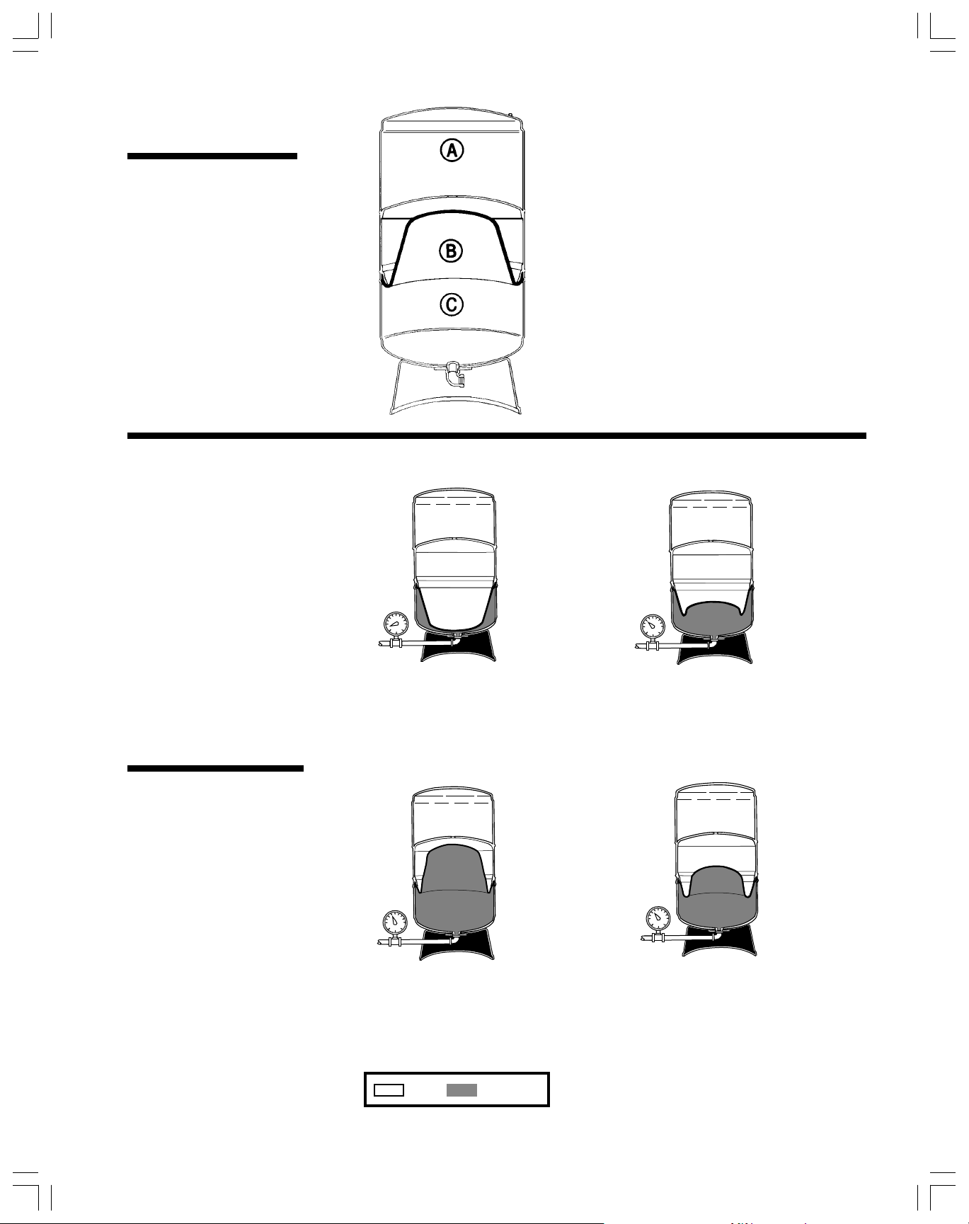
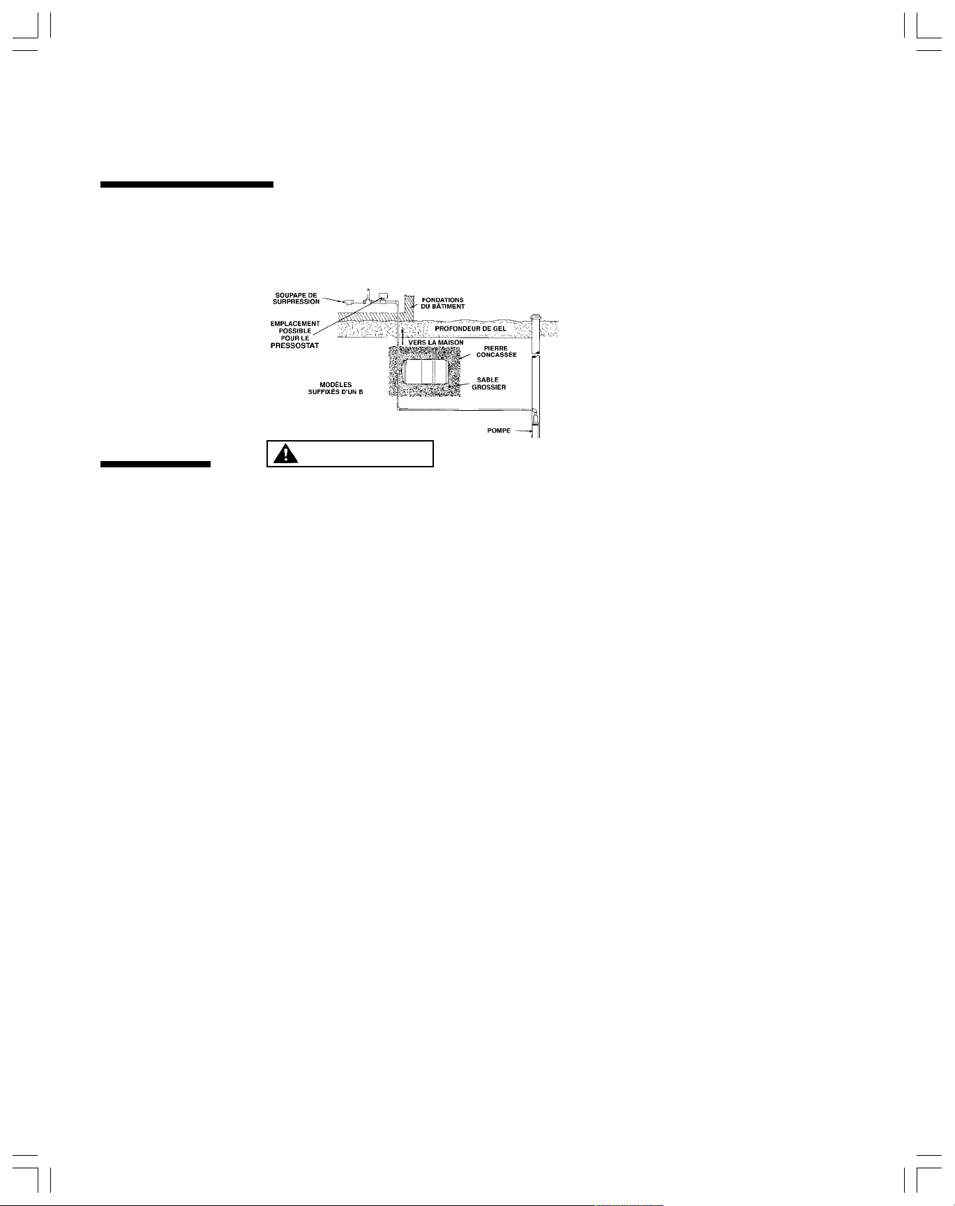
The water system tank consists of a steel tank
(A) containing a sealed-in-place heavy duty
diaphragm (B) which separates air from the
water. The portion of the tank where water is
stored (C) is lined to isolate water from the
metal tank. This protects the tank from
corrosion.
water system
designed to
operate at a
30/50 psig
pressure
switch
setting.
30
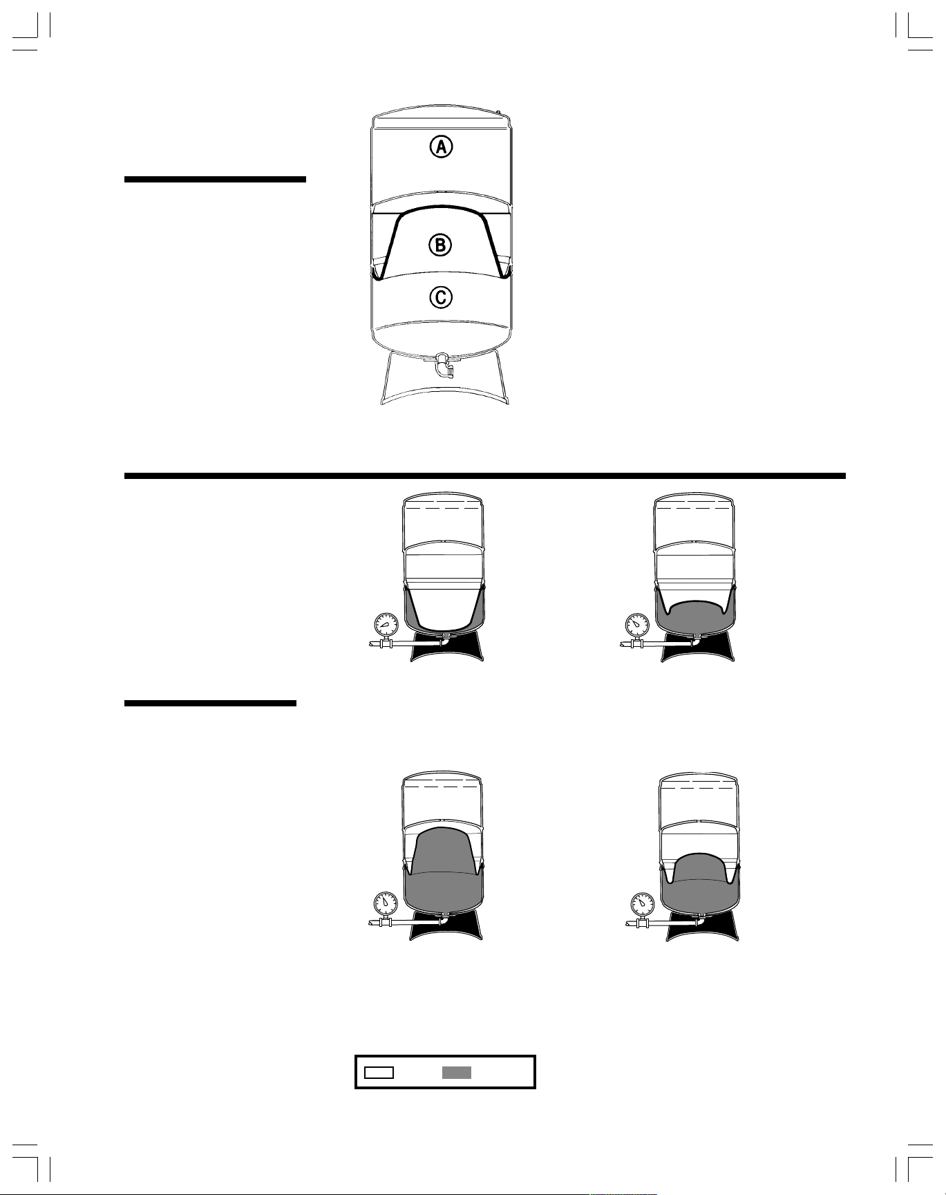
Prior to shipping, the tank
1.
is pressurized to a standard
precharge as defined in
“OPERATION” part of this
manual.
50
As water enters the tank, the
2.
air above the diaphragm is
compressed and its volume
is reduced by the volume of
water that enters.
The pressure in the tank
3.
rises. Water continues to
enter until the pump cut-out
pressure is reached. The
pump shuts off and the tank
is now filled.
AIR WATER
The pressure in the air chamber
4.
forces water into the system
when a demand is made
without causing the pump to
operate immediately. When
the pressure in the chamber
finally drops to the pump cutin pressure, the pump switch
activates the pump and
3
repeats the filling cycle.
Page 4
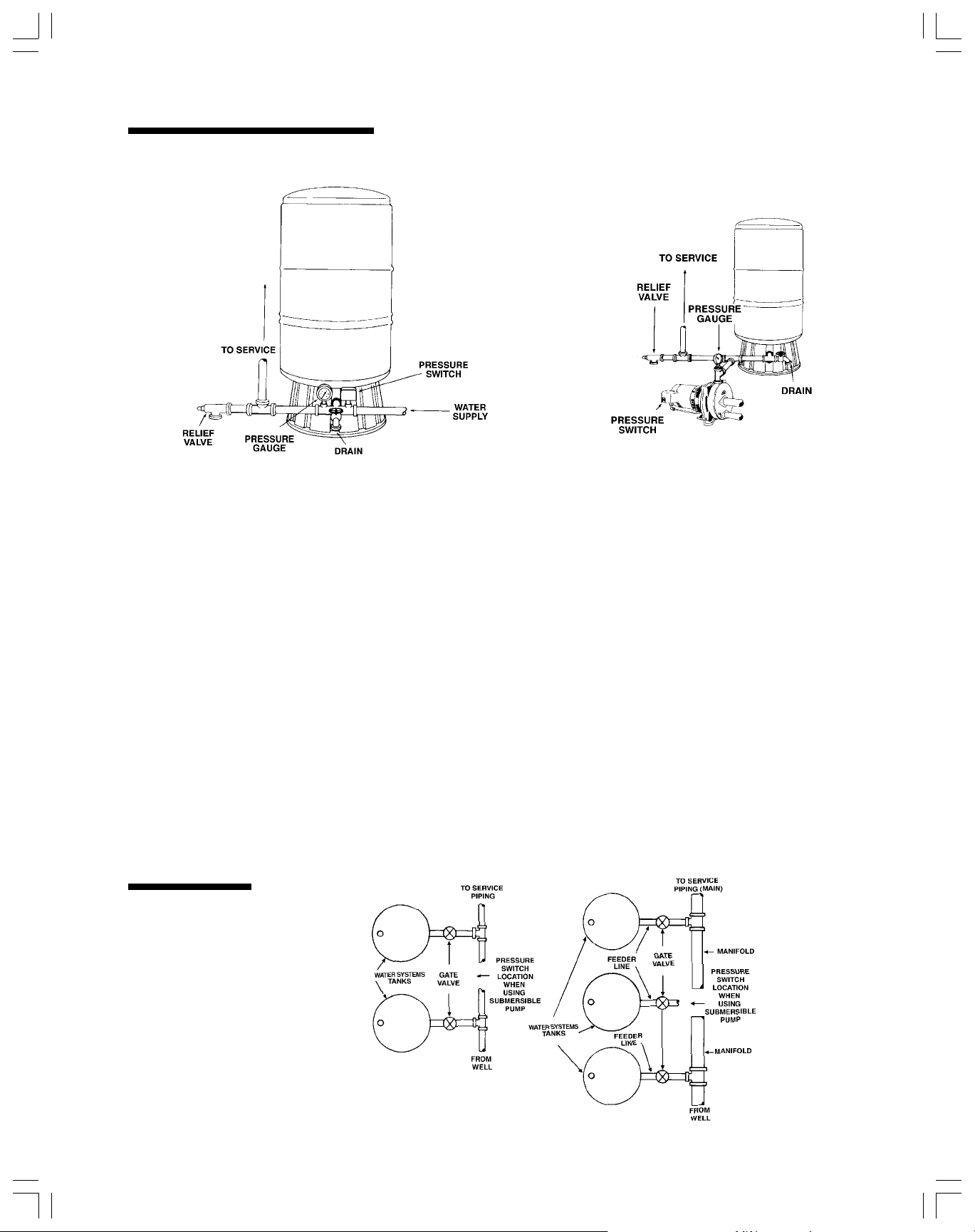
Installation Procedures
TYPICAL SUBMERSIBLE
PUMP INSTALLATION
1. The water system tank should be installed as close
as possible to the pressure switch (24 inches or less)
to reduce the adverse effect of friction loss and
elevation differences.
2. Disconnect electric power.
3. Drain system and remove old tank. On new system
installation this step is unnecessary.
4. Locate the water system tank on a firm, level surface
with adequate drainage. Typical installations are
shown in the following section.
TYPICAL JET
PUMP INSTALLATION
5. If your system is capable of exceeding a working
pressure of 125 psig (typically submersible pumps),
install a pressure relief valve (rated at 125 psig or
less, but greater than turn-off pressure) in the system
near the tank. The valve should be the same pipe
size as the tank outlet.This is not necessary on tankmounted jet pump units.
6. Connect tank to the pump discharge line using the
same size pipe as the pump tap, or larger.
WARNING: Hold 90° tank street elbow with wrench
when threading and tightening connecting pipe.
7. The tank should be flushed 5 times prior
to household use. (See operation section)
Multiple
Tank
Installation
Procedure
Water system tanks can be connected
together to increase the supply of usable
water (drawdown). Two tanks of the same
size will double the supply and three tanks
will triple the supply. When using a high
4
capacity pump, the manifold and pressure switch
assembly must be installed in the pipe line as close
to the center of the tanks as possible. Manifold and
main should be 2 times the size of the feederline.
Page 5
Underground
Pressure
Tanks
Operation
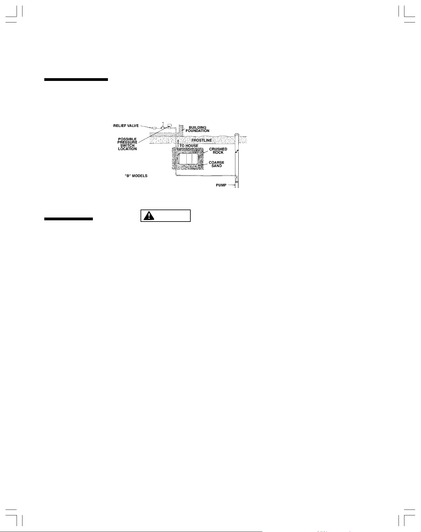
Buried model water system tanks are
designed for direct burial and can be
installed in the horizontal or vertical position.
To eliminate the danger of freezing, tank
must be buried below frost line.
The following steps should be taken when
installing the water system tank.
1. Make sure that tank will be buried below
frost line and above water table.
WARNING
2. Use galvanized or plastic pipe
for section of pipe buried in the ground.
3. Check tank precharge. Tank precharge
must be adjusted to the pressure required
by the pressure switch setting (see section
on Operation).
4. Install tank on firm rock-free earth.
5. The water line from the pump to the
tank and from the tank to the pressure
switch location should be the same size.
6. Check system for performance
and inspect for leaks.
7. Backfill hole with sand or rock-free dirt.
Firmly tamp fill to prevent settling.
8. Make note of tank location so that it
can be easily located at a later time.
THESE WATER TANKS ARE DESIGNED FOR OPERATION ON AMBIENT TEMPERATURE WATER SYSTEMS
LIMITED TO A MAXIMUM WORKING PRESSURE OF 125 POUNDS PER SQUARE INCH GAUGE (PSIG). IF YOUR
SYSTEM HAS THE ABILITY TO EXCEED 125 PSIG WORKING PRESSURE (100 PSIG IF THIS IS A PUMP MOUNTED
UNIT), A SUITABLE SAFETY DEVICE MUST BE INSTALLED. THIS CAN BE EITHER A HIGH PRESSURE ELECTRICAL
CUT-OFF SWITCH AND/OR A PRESSURE RELIEF VALVE. FAILURE TO FOLLOW THESE INSTRUCTIONS CAN
CAUSE TANK RUPTURE AND RESULT IN PERSONAL INJURY AND/OR PROPERTY DAMAGE.
Before you operate the system you must check your water system tank and system to ensure proper operation.
All water system tanks are precharged at the factory. All 8 and 11 inch diameter tanks are precharged at 18 psig. The 15
inch diameter tanks are precharged at 28 psig while the 22 and 26 inch diameter tanks are precharged to 38 psig. The
final precharge pressure should always be 2 to 3 psig below the cut-in (pump turns on) pressure of the pressure switch.
Release air or add air as required using the following procedure.
1. Determine the pump cut-in pressure setting. The pressure switch should have this information located on/in the
cover.
2. With no water in the tank, measure the precharge of the water system tank using an accurate pressure gauge at the
air valve (similar to an auto tire gauge).
LESS
3. Release air or add air to the tank to make the pressure in the tank 2 to 3 psig
setting.
4. It will be necessary to expel air from the piping system on new installations. To do this open all faucets and turn on the
pump. Observe that a mixture of water and air will sputter from the faucet. Run the system until a steady flow of
water exists. Open and close the faucets several times to assure that all air has been removed. If streams do not
become steady, an air leak may exist. Check for leaks on suction side piping.
5. It may be necessary to make final adjustments on the system pressure switch setting because at times the actual
pressure switch setting will vary from what is stated on the cover. Such variation, though not harmful, could cause a
momentary lag of water delivery. To make this adjustment the following steps should be followed:
a. Fill the system until the pump shuts off.
b. Open a faucet and drain the water system tank until the pump starts.
c. If there is a pause in the water flow from the time the water system tank is emptied and the pump starts up
again, decrease the air pressure in the tank until it is 2 to 3 psig below the cut-in pressure setting. (See
Trouble Shooting section 3(a-b) for procedure)
d. Close the faucets and refill the water system tank. Repeat steps (b) and (c) if necessary until there no
longer is a pause in water flow.
5
than the pump cut-in pressure
Page 6
Trouble
LEDOM
.ON
SNOISNEMID
METSYSTA.SLAGNINWODWARD
:FOEGNARERUSSERPGNITAREPO
.XAM
NWODWARD
.LOV
).SLAG(
METSYS
NOITCENNOC
)SEHCNI(
RETEMAIDTHGIEHGISP04/02GISP05/03GISP06/04
SLEDOMENIL-NI
P6ET 8 61/51117.06.05.02.1MTPN"4/3
P51ET 1161/51317.14.12.17.2MTPN"4/3
P52ET 1161/1321.36.22.25.4MTPN"4/3
P54ET 8/35161/1121.53.47.34.8MTPN"1
SLEDOMGNIDNATSEERF
548/35161/51421.53.47.34.8FTPN"1
068/3518/3233.71.63.51.21FTPN"1
088/35161/9939.87.77.69.31FTPN"1
0018/3514/1748.119.96.88.31FTPN"1
0412261/9635.619.311.213.72FTPN"4/11
002228/5849.320.024.713.93FTPN"4/11
05262649.039.525.228.05FTPN"4/11
0622261/11062.132.628.227.44FTPN"4/11
0536261/3169.249.535.135.07FTPN"4/11
SLEDOMDEIRUB
B548/35161/1121.53.47.34.8MTPN"1
B068/3512/1823.71.63.51.21MTPN"1
B0412261/3235.619.311.213.72MTPN"4/11
B002224/1449.320.024.713.93MTPN"4/11
ET
ET
ET
ET
ET
ET
ET
ET
ET
ET
ET
ET
ET
Shooting
IF YOU THINK YOU HAVE A PROBLEM WITH YOUR WATER SYSTEM TANK, YOU SHOULD MAKE THE FOLLOWING
TESTS AND OBSERVATIONS BEFORE YOU CALL YOUR PROFESSIONAL DEALER.
1. Observe water system operation and note any unusual occurrence such as water spurting from a faucet rather than a
steady flow (indicates air in the system) or short cycling of the pump (rapid starts and stops).
2. In the event that evidence of a small leak near the water fitting appears, check at elbow. The introduction of cold
water to a warm tank may form condensation especially in warmer climates. It is important to provide adequate
drainage.
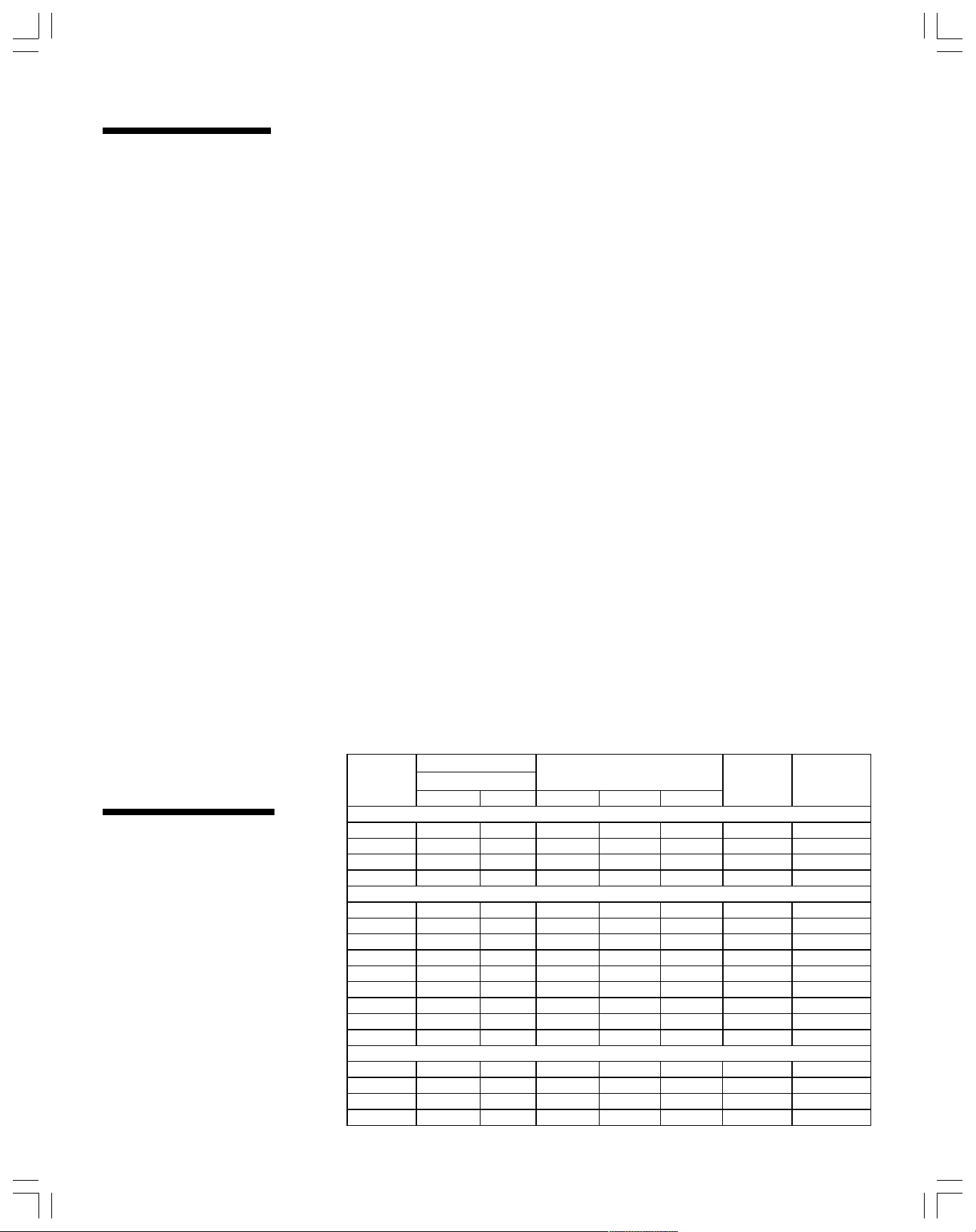
3. Measure the water drawdown by collecting water in a sufficiently sized container from the time the pump is off (cut-off
point) to the time it turns on (cut-in point). Compare the gallons with that shown in the table below for your model of
tank. If the volume is close to that shown in the table, your system is operating properly.
a. Air charge in Tank. Turn off electric power to the pump. Open faucet nearby and drain the tank completely.
Check the pressure in the water system tank using a standard, high quality tire gauge. If the air pressure in
the tank is below the pump cut-in setting by more than 3 psi, add air to the tank to make it 2 psi less than the
cut-in setting. Replace the valve stem cap. Check around the air stem using a soapy solution to check for
leaks around welds and seams on the remainder of the tank. If a leak appears on the tank itself then
replacement of the tank will be necessary.
b. Pressure Switch Setting. Start the pump and allow the system pressure to shut off pump. Note both the
cut-in and cut-off pressure values on gauge. The difference should not exceed 25 psi. Adjust the pressure
switch if necessary after shutting off the electric power to show a difference of 20 psi. Instructions from the
pressure switch manufacturer will explain how to do this. Test the system after adjusting the limits. If the
pressure switch can’t maintain the proper differential then it may need replacement, not the tank
.
Tank
Specifications
6
Page 7

Limited
Warranty
A.O. Smith Corporation, the warrantor, extends the following LIMITED WARRANTY to the owner of this water system tank.
1. TANK
If within five years after installation the tank or a part thereof shall prove upon examination by the warrantor to be
defective in material or workmanship, the warrantor, at his option, shall exchange or repair such part or portion. The
warranty on the replacement tank will be limited to the unexpired term of the original warranty.
2. CONDITIONS AND EXPECTA TIONS
This warranty shall apply only when the tank is installed in accordance with local plumbing and building codes,
ordinances and regulations, and good industry practices. In addition, a high pressure electrical cut-off switch and/or a
pressure relief valve must be installed when the tank is installed on an ambient temperature water system whose
maximum working pressure has the ability to exceed 125 pounds per square inch gauge (psig). (100 pounds per
square inch guage (psig) on certain models)
a. This warranty shall apply only when the water system is used:
(1) on ambient temperature water systems at pressures not exceeding the working
pressure for the water system;
(2) in the United States, its territories or possessions, and Canada.
b. Any accident to the water system tank, any misuse, abuse (including freezing) or alteration of it, any operation of
it in a modified form, any attempt to repair tank leaks will void this warranty.
3. SERVICE AND REPAIR EXPENSE
Under this limited warranty the warrantor will provide only a replacement tank or part thereof. The owner is
responsible for all other costs. Such costs may include but are not limited to:
a. Labor charges for service, removal, repair, or reinstallation of the water system or any component part,
b. Shipping and delivery charges for forwarding the new tank or replacement part from the nearest distributor and
returning the claimed defective tank or part to such distributor except in the state of California where such
charges are the manufacturer’s responsibility.
4. LIMITATION ON IMPLIED WARRANTIES
Implied warranties, including any warranty of merchantability imposed on the sale of this tank under state law are
limited to five (5) year duration for the tank or any of its parts. Some states do not allow limitations on how long an
implied warranty lasts, so the above limitation may not apply to you.
5. CLAIM PROCEDURES
Any claim under this warranty should be initiated with the dealer who sold the tank, or with any other dealer handling
the warrantor’s products. If this is not practicable, the owner should contact:
a. The warrantor will only honor replacement with identical or similar tank or parts thereof which are manufactured
or distributed by the warrantor.
b. Dealer replacements are made subject to in-warranty validation by warrantor.
6. DISCLAIMERS
NO OTHER EXPRESS WARRANTY HAS BEEN OR WILL BE MADE ON BEHALF OF THE WARRANTOR WITH
RESPECT TO THE TANK OR THE INSTALLATION, OPERATION, REPAIR OR REPLACEMENT OF THE TANK.
THE WARRANTOR SHALL NOT BE RESPONSIBLE FOR WATER DAMAGE, LOSS OF USE OF THE UNIT,
INCONVENIENCE, LOSS OR DAMAGE TO PERSONAL PROPERTY, OR OTHER CONSEQUENTIAL DAMAGE.
THE WARRANTOR SHALL NOT BE LIABLE BY VIRTUE OF THIS WARRANTY OR OTHERWISE FOR DAMAGE
TO ANY PERSONS OR PROPERTY, WHETHER DIRECT OR INDIRECT, AND WHETHER ARISING IN
CONTRACT OR IN TORT.
a. Some states do not allow the exclusion or limitation of the incidental or consequential damages, so the above
limitation or exclusion may not apply to you.
. This warranty gives you specific legal rights, and you may also have other rights which vary from
b
U.S Customers Canadian Customers
A.O. Smith Corporation A.O. Smith Corporation
5621 W. 115th Street P.O. Box 310-768 Erie Street
Alsip, IL 60803 Stratford, Ontario N5A 6T3
800-323-2636 or 708-489-4600 Telephone: (519) 271-5800
state to state.
Fill in the following for your own reference. Keep it. Registration is not a condition of warranty. The model
and serial number are found on the water system tank.
Model No.______________Serial No.____________________________Date Installed_________________
Part No. 205351-000
Dealer’s Name__________________________________________________________________________
Dealer’s Address____________________________________________Phone No.____________________
City & State (Provincial)_______________________________________Zip (Postal Code)______________
Dangerous Goods Permit No. SU 5099 (Ren2) - by road or rail vehicle only, expiration date: March 31, 2003 (Pending
Renewals)
7
Page 8

Lisez et observez
les consignes de
ll s’agit là d’un symbole de mise en garde pour votre sécurité. Lorsque vous voyez ce
symbole sur votre système ou dans ce manuel, cella veut dire que vous devez faire
attention car il y a un risque de blessures.
sécurité !
DANGER
AVERTISSEMENT
ATTENTION
Consignes de
sécurité
Le mot DANGER prévient des risques qui causeront des blessures graves, la mort ou
des dommages matériels importants si l’on n’en tient pas compte.
Le mot ADVERTISSEMENT prévient des risques qui pourraient causer des blessures
graves, la mort ou des dommages matériels importants si l’on n’en tient pas compte.
Le mot ATTENTION prévient des risques qui pourraient causer des blessures
mineures ou des dommages matériels si l’on n’en tient pas compte.
Le mot AVIS attire votre attention sur des directives spéciales qui sont importantes,
mais qui ne convement pas des risque ni des dangers.
Lisez attentivement toutes les consignes de sécurité dans ce manuel et sur le
système, puis suivez-les bien.
Gardez les étiquettes de sécurité en bon état. Remplacez les étiquettes de sécurité
manquantes ou endommagées.
1. AVERTISSEMENT — CE RÉSERVOIR À EAU A ÉTÉ CONÇU POUR FONC-
TIONNER SUR UN SYSTÈME D’ALIMENTATION EN EAU À UNE TEMPÉRATURE
AMBIANTE ET À UNE PRESSION DE SERVICE MAXIMALE DE 125 lb/po
VOTRE SYSTÈME PEUT DÉPASSER UNE PRESSION DE 125 lb/po
100 lb/po
ALORS INSTALLER UN DISPOSITIF DE SÉCURITÉ APPROPRIÉ. CE DISPOSITIF
POURRAIT ÊTRE UN PRESSOSTAT ÉLECTRIQUE HAUTE PRESSION OU UNE
SOUPAPE DE SURPRESSION, OU LES DEUX. L’INOBSERVATION DE CES
CONSIGNES POURRAIT CAUSER UNE RUPTURE DU RÉSERVOIR ET ENTRAÎNER DES BLESSURES ET DES DOMMAGES MATÉRIELS.
2
S’IL S’AGIT D’UN RÉSERVOIR MONTÉ SUR UNE POMPE), IL FAUT
2
(OU DE
2
. SI
2.C’est à vous qu’incombe la responsabilité de vous assurer que votre installation est
conforme aux exigences de tous les codes nationaux et provinciaux de plomberie et
d’électricité.
3.
DANGER — Avant de procéder à l’installation ou à l’entretien de votre
pompe ou de votre réservoir, assurez-vous que son alimentation électrique a
été coupée.
4.Si un réservoir galvanisé ordinaire est remplacé par un réservoir à air captif pour
systèmes d’alimentation en eau, bouchez les orifices de purge et enlevez les régulateurs de volume d’air ou autres dispositifs d’admission d’air du système.
ATTENTION — Ce réservoir de stockage a été conçu pour les systèmes
5.
d’alimentation en eau à température ambiante (température maximale de 120
en vigueur depuis février 2001). Son emploi à d’autres fins pourrait entraîner
une défaillance du réservoir et même des blessures et annule la garantie.
6.Le système complet, c’est-à-dire la pompe, le réservoir et la tuyauterie, doit
être protégé contre le gel. Si l’on néglige cette précaution, il sera sérieusement
endommagé, et sa garantie deviendra nulle et non avenue.
7.
DANGER — Le réservoir contient de l’air sous pression. Ne le percez pas.
Ne jetez jamais le réservoir dans le feu ni dans un incinérateur.
o
F
8
Page 9

Le concept du
40
45
réservoir pour
Systèmes d’alimentation en eau
Fonctionnement du
réservoir dans un
Le réservoir pour systèmes d’alimentation en eau
ne fait pas qu’emmagasiner de l’eau ; il aide aussi
à protéger votre système d’alimentation en eau.
Le rèservoir a été mis au point pour assurer un
approvisionnement en eau adéquat avec un débit
suffisant, même quand la pompe est arrêtée, afin
d’économiser de l’énergie et de prolonger la
durée utile de son moteur, en réduisant les
démarrages donc le fonctionnement cyclique au
minimum. On protège ainsi les autres organes du
système.
Le réservoir pour systèmes d’alimentation en eau
comprend un récipient en acier (A) contenant une
membrane robuste (B) scellée en place qui
sépare l’air et l’eau. La portion du réservoir où
l’eau est emmagasinée (C) comporte un
revêtement qui isole l’eau de la paroi métallique.
Ceci protège le réservoir contre la corrosion.
système d’alimentation en eau et
dans une plage de
pression
manométrique de
30-50 lb/po
2
30
Avant l’expédition, de l’air est injecté
1.
dans le réservoir jusqu’à ce que la
pression interne atteigne la valeur
standard définie dans la section
« UTILISATION » de ce manuel.
50
À mesure que l’eau pénètre
2.
dans le réservoir, l’air audessus de la membrane est
comprimé et subit une diminution de volume égale au
volume de l’eau qui entre dans
le réservoir.
La pression dans le réservoir
3.
augmente. L’eau continue d’y
pénétrer jusqu’à ce que la
pression d’arrêt de la pompe soit
atteinte. La pompe s’arrête, et le
réservoir est alors plein..
AIR EAU
9
Quand on a besoin d’eau, l’air
4.
sous pression force l’eau dans le
système sans que la pompe se
mette en marche immédiatement.
Lorsque la pression de l’air baisse
au point d’atteindre la pression
d’enclenchement du pressostat
(manostat), la pompe redémarre et
répète le cycle de remplissage.
Page 10

Marche à suivre pour l’installation
INSTALLATION TYPE À POMPE
SUBMERSIBLE
1. Le réservoir pour systèmes d’alimentation en eau devrait
être installé aussi près que possible du pressostat
(24 pouces ou moins) pour diminuer l’effet nuisible de la
perte de charge par frottement et des différences
d’élévation.
2. Coupez le courant électrique.
3. Vidangez le système et enlevez le vieuxréservoir. S’il
s’agit d’une nouvelle installation, cette étape n’existe
évidemment pas.
4. Placez le réservoir sur une surface de niveau, dans un
endroit muni d’un drain suffisamment gros.
5. Si votre système est capable de dépasser une pression
de service de 125 lb/po
submersible), posez une soupape de surpression sur le
2
(habituellement avec une pompe
INSTALLATION TYPE
À POMPE À JET
système, à proximité du réservoir. Cette soupape devrait
avoir la même section de passage que la sortie du
réservoir. Cette précaution n’est pas nécessaire pour une
installation à pompe à jet montée sur le réservoir.
6. Raccordez le réservoir à la conduite de refoulement de la
pompe. Pour cela, servez-vous d’un tuyau ayant au
moins le même diamètre que l’orifice de la pompe.
AVERTISSEMENT : Quand vous vissez et serrez le tuyau
de raccordement, immobilisez à l’aide d’une clé le coude
mâle et femelle à 90 degrés du réservoir.
7. Le réservoir devrait être rincé à cinq reprises avant de
servir à des fins domestiques.
D’autres installations types sont montrées dans la section
qui suit.
Installation à
réservoirs
multiples
On peut raccorder plusieurs réservoirs pour
systèmes d’alimentation en eau pour accroître
la capacité utile du système. Deux réservoirs
de même capacité permettront de doubler le
stockage, tandis que trois le tripleront. Quand
vous utilisez une pompe à grand débit, le
10
collecteur-répartiteur et le pressostat doivent
être posés sur la canalisation, aussi près que
possible du centre des réservoirs. Le diamètre
du collecteur-répartiteur et de la canalisation
principale devrait être le double de celui de la
conduite d’alimentation.
Page 11
Réservoirs avec
précompression
enterrés
Utilisation
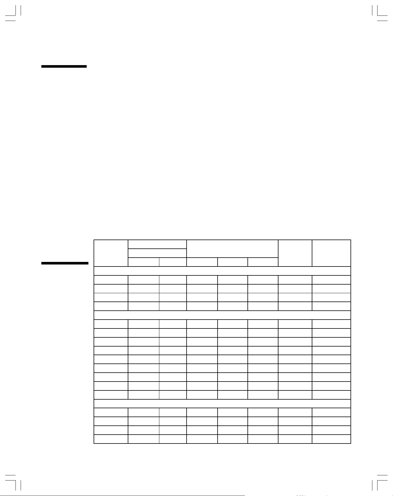
On peut enterrer les réservoirs pour systèmes
d’alimentation en eau à l’horizontale ou à la
verticale. Afin d’éliminer les risques de gel,
tout réservoir doit être enterré en dessous de
la profondeur de gel.
Voici la marche à suivre quand on installe un
modèle suffixé d’un B :
1. Veillez à ce que le réservoir soit enterré
sous la ligne de gel, mais au-dessus de la
nappe phréatique.
2. Pour les canalisations qui seront dans le
A VERTISSEMENT
sol, utilisez des tuyaux galvanisés ou en
plastique.
3. Vérifiez la pression de l’air du réservoir. Elle
doit être réglée selon la pression de
réglage du pressostat. (Voyez la section
Utilisation.)
4. Installez le réservoir sur un lit de terre
ferme et exempte de roches et de cailloux.
5. Les tuyaux reliant la pompe, le réservoir et
le pressostat devraient avoir le même
diamètre.
6. Vérifiez les performances du système et
assurez-vous que celui-ci ne fuit pas.
7. Remblayez le trou avec du sable ou de la
terre dépourvue de roches. Pilonnez
fermement le remblai pour bien immobiliser
le réservoir.
8. Prenez note de l’emplacement du réservoir,
afin de pouvoir le retrouver facilement en
cas de besoin.
CE RÉSERVOIR À EAU A ÉTÉ CONÇU POUR FONCTIONNER SUR UN SYSTÈME D’ALIMENTATION EN EAU À UNE
2
TEMPÉRATURE AMBIANTE ET À UNE PRESSION DE SERVICE MAXIMALE DE 125 lb/po
DÉPASSER UNE PRESSION DE 125 lb/po
2
(OU DE 100 lb/po2 S’IL S’AGIT D’UN RÉSERVOIR MONTÉ SUR UNE POMPE), IL
. SI VOTRE SYSTÈME PEUT
FAUT ALORS INSTALLER UN DISPOSITIF DE SÉCURITÉ APPROPRIÉ. CE DISPOSITIF POURRAIT ÊTRE UN
PRESSOSTAT ÉLECTRIQUE HAUTE PRESSION OU UNE SOUPAPE DE SURPRESSION, OU LES DEUX. L’INOBSERVATION DE CES CONSIGNES POURRAIT CAUSER UNE RUPTURE DU RÉSERVOIR ET ENTRAÎNER DES BLESSURES ET
DES DOMMAGES MATÉRIELS.
Avant d’utiliser le système, vous devez en vérifier le bon fonctionnement et celui du réservoir pour systèmes d’alimentation en
eau.
L’air de tous les réservoirs pour systèmes d’alimentation en eau est précomprimé en usine. La pression manométrique des
2
réservoirs de 8 et de 11 pouces de diamètre est de 18 lb/po
celle des réservoirs de 22 et de 26 pouces de diamètre, de 38 lb/po
inférieure de 2 à 3 lb/po
2
à la pression d’enclenchement du pressostat (démarrage de la pompe). Au besoin, augmentez ou
, celle des réservoirs de 15 pouces de diamètre, de 28 lb/po2, et
2
. La pression de l’air précomprimé devrait toujours être
réduisez la pression de l’air comme suit :
1. Déterminez la pression de démarrage de la pompe. Vous devriez trouver ce renseignement sur ou sous le couvercle du
pressostat.
2. Le réservoir étant vide d’eau, placez un manomètre de précision pour pneus sur la valve à air comprimé du réservoir pour
systèmes d’alimentation en eau et mesurez la pression interne de l’air.
3. Relâchez de l’air ou ajoutez-en dans le réservoir pour que la pression manométrique interne soit INFÉRIEURE de 2 à 3 lb/
2
à la pression de démarrage de la pompe.
po
4. Dans le cas d’une nouvelle installation, vous devrez chasser l’air de la tuyauterie. Pour ce faire, ouvrez tous les robinets et
mettez la pompe en marche. Vous remarquerez qu’un mélange d’eau et d’air jaillira par à-coups du ou des robinets. Laissez
fonctionner le système jusqu’à ce que l’écoulement de l’eau soit stable. Ouvrez et fermez les robinets à plusieurs reprises
pour vous assurer que tout l’air a été chassé du système. Si le jet d’eau ne devient pas constant, il pourrait y avoir une fuite
d’air. Examinez bien la tuyauterie d’aspiration.
5. Il pourrait être nécessaire d’effectuer un réglage du pressostat, dont les pressions de
fonctionnement pourraient être différentes de celles qui sont indiquées sur ou sous le couvercle. Sans être dangereux, un
tel écart pourrait causer un arrêt momentané de l’écoulement de l’eau. Réglez le pressostat comme suit :
a) Faites fonctionner la pompe jusqu’à ce que le réservoir soit plein et que cette dernière s’arrête.
b) Ouvrez un robinet et videz le réservoir pour systèmes d’alimentation en eau jusqu’à ce que la pompe se remette en
marche.
c) Si l’écoulement d’eau s’arrête un peu entre le moment où le réservoir pour systèmes d’alimentation en eau est vide et le
2
redémarrage de la pompe, diminuez la pression d’air dans le réservoir jusqu’à ce qu’elle soit inférieure de 2 à 3 lb/po
à la
pression de démarrage. (Voyez le guide de dépannage, section 3 (a-b) du diagnostic des anomalies, pour savoir comment
procéder).
d) Fermez le robinet et remplissez le réservoir pour systèmes d’alimentation en eau. Au besoin, répétez les étapes b) et c)
jusqu’à ce qu’il n’y ait plus d’interruption dans l’écoulement de l’eau.
11
Page 12

Diagnostic
des
anomalies
SI VOUS PENSEZ AVOIR UN PROBLÈME AVEC VOTRE RÉSERVOIR POUR SYSTÈMES D’ALIMENTATION EN EAU, VOUS DEVRIEZ EFFECTUER LES ESSAIS SUIVANTS AVANT D’APPELER VOTRE
DÉTAILLANT PROFESSIONNEL.
1. Observez le fonctionnement du système et prenez note de tout fait inhabituel : de l’eau jaillissant par
à-coups du robinet (présence d’air) au lieu de former un filet continu ou bien un fonctionnement
cyclique trop court (démarrages et arrêts trop fréquents).
2. S’il semble y avoir une petite fuite près d’un raccord, vérifiez d’abord le coude. L’introduction d’eau
froide dans un réservoir relativement chaud peut entraîner la formation de condensation, particulièrement dans les régions chaudes. Il est important de prévoir un drainage suffisant.
3. Mesurez la capacité utile du réservoir en en recueillant l’eau dans un récipient assez grand, à partir du
moment où la pompe s’arrête jusqu’au moment où elle se remet en marche. Comparez la quantité
recueillie avec ce qu’indique la table ci-dessus pour votre modèle de réservoir. Si le volume est à prés
égal au volume stipulé dans la table, cela veut dire que votre système fonctionne correctement, sinon
vérifiez les deux points suivants :
a) Pression d’air dans le réservoir. Coupez le courant électrique qui alimente la pompe. Ouvrez un
robinet à proximité du réservoir et videz ce dernier complètement. Au moyen d’un bon manomètre
pour pneus, vérifiez la pression d’air dans le réservoir. Si la pression d’air est bien inférieure à la
pression de démarrage de la pompe par plus de 3 lb/po
ce que la pression de l’air ait 2 lb/po
2
de moins que la pression de démarrage. Revissez le capuchon
2
, introduisez de l’air dans le réservoir jusqu’à
sur la valve à air comprimé. Avec une solution savonneuse, voyez s’il y a une fuite autour de la valve,
ainsi que près des soudures et des joints du réservoir. Si vous décelez une fuite sur le réservoir, il
faudra alors le remplacer.
b) Réglage du pressostat. Mettez la pompe en marche et laissez la pression du système arrêter la
pompe. Notez les pressions manométriques de démarrage et d’arrêt sur le manomètre. Leur diffé-
2
rence ne devrait pas dépasser 25 lb/po
le pressostat pour que la différence entre les deux pressions soit de 20 lb/po
. Au besoin, après avoir coupé l’alimentation électrique, réglez
2
. Consultez les instructions fournies par le fabricant du pressostat pour savoir comment procéder à ce réglage. Mettez le
système à l’essai après le réglage. Si le pressostat ne peut maintenir la pression différentielle appropriée, vous devrez peut-être alors le remplacer et non le réservoir.
Caractéristiques
des réservoirs
EDORÉMUN
ELÈDOM
SNOISNEMID
)SECUOP(
ERTÈMAIDRUETUAHop/bl04-02
2
2
op/bl05-03
CEVA)SUlag(ELITUÉTICAPAC
EUQIRTÉMONAMNOISSERP
:EDECIVRESED
2
op/bl06-04
NOITASILANACRUSSÉTNOMSELÈDOM
ET
P68 61/51117,06,05,02,1MTPN,4/3
ET
P511161/51317,14,12,17,2MTPN,4/3
ET
P521161/1321,36,22,25,4MTPN,4/3
ET
P548/35161/1121,53,47,34,8MTPN,1
TUOBEDSELÈDOM
548/35161/51421,53,47,34,8FTPN,1
ET
068/3518/3233,71,63,51,21FTPN,1
ET
088/35161/9939,87,77,69,31FTPN,1
ET
0018/3514/1748,119,96,88,31FTPN,1
ET
0412261/9635,619,311,213,72FTPN,4/11
ET
002228/5849,320,024,713,93FTPN,4/11
ET
05262649,039,525,228,05FTPN,4/11
ET
0622261/11062,132,628,227,44FTPN,4/11
ET
0536261/3169,249,535,135,07FTPN,4/11
ET
SÉRRETNESELÈDOM
ET
B548/35161/1121,53,47,34,8MTPN,1
ET
B068/3512/1823,71,63,51,21MTPN,1
ET
B0412261/3235,619,311,213,72MTPN,4/11
ET
B002224/1449,320,024,713,93MTPN,4/11
ÉTICAPAC
ELITU
ELAMIXAM
)SUlag(
SDROCCAR
)SECUOP(
12
Page 13

Garantie limitée
A.O. Smith Corporation, le garant, offre la GARANTIE LIMITÉE suivante au propriétaire de ce réservoir pour systèmes d’alimentation en eau.
1. RÉSERVOIR
Si, dans les cinq années qui suivent l’installation initiale, le garant constate, après examen, que le réservoir pour systèmes d’alimentation en
eau ou l’un de ses éléments est défectueux quant aux matériaux ou à la fabrication, le garant pourra, à son choix, le remplacer ou réparer
l’élément en question. La garantie pour un réservoir ainsi remplacé ou réparé sera limitée à la portion non expirée de la garantie initiale.
2. MODALITÉS ET ATTENTES
Cette garantie ne s’applique que si le réservoir pour systèmes d’alimentation en eau est installé conformément aux codes de plomberie et de
construction, ainsi qu’aux ordonnances et règlements en vigueur dans la localité et aux règles de l’industrie. En outre, il faudra que le système
soit muni d’un pressostat électrique haute pression ou d’une soupape de surpression, ou des deux, si le réservoir pour systèmes d’alimentation en eau est installé dans un système d’alimentation en eau utilisé à une température ambiante et à une pression manométrique de service
maximale pouvant dépasser 125 lb/po2 ( 100 lb/po2 pour certains modèles ).
a) La présente garantie ne s’applique que si le réservoir est utilisé :
1° avec un système d’alimentation en eau à une température ambiante à une pression ne dépassant pas la pression de service
prévue pour le réservoir ;
2° aux États-Unis et dans leurs territoires ou possessions, ainsi qu’au Canada.
b) Tout bris accidentel du réservoir pour systèmes d’alimentation en eau, tout usage incorrect ou abusif (y compris le gel), toute modification
ou toute utilisation du réservoir modifié ou bien toute tentative pour réparer une fuite dans le réservoir annulera cette garantie.
3. FRAIS D’ENTRETIEN ET DE RÉPARATION
Aux termes de la présente garantie limitée, le garant ne s’engage qu’à remplacer le réservoir pour systèmes d’alimentation en eau ou sa pièce
défectueuse. Tous les autres frais sont à la charge du propriétaire. Ces frais peuvent inclure, entre autres points :
a) les frais de main-d’œuvre pour l’entretien, la dépose, la réparation ou la réinstallation du réservoir ou de l’un de ses éléments consti
tuants ;
b) les frais d’expédition et de livraison pour l’envoi, par le distributeur le plus proche, du nouveau réservoir ou de sa pièce de rechange, et
pour le renvoi à ce distributeur de la pièce ou du réservoir jugés défectueux, sauf en Californie, où ces frais sont imputés au fabricant.
4. LIMITATION DES GARANTIES IMPLICITES
Les garanties implicites, y compris toute garantie de qualité marchande imposée en vertu d’une loi, sont limitées à une durée de cinq (5) ans
pour le réservoir et chacune de ses pièces. Comme certaines provinces ne permettent pas de limiter la durée d’une garantie implicite, il se
peut que cette limite ne s’applique pas dans votre cas.
5. RÉCLAMATIONS
Toute réclamation faite en vertu de la présente garantie doit être adressée au détaillant qui a vendu le réservoir ou à tout autre détaillant
autorisé à s’occuper des produits du garant. Si c’est impossible, le propriétaire devrait alors communiquer avec :
a) Le garant se bornera à remplacer par des articles identiques ou semblables le réservoir ou ses pièces, qui sont fabriquées ou distribuées
par lui.
b) Les remplacements effectués par un détaillant sont sujets à acceptation aux termes de la garantie par le garant.
6. LIMITATION DE RESPONSABILITÉ
AUCUNE AUTRE GARANTIE EXLICITE N’A ÉTÉ NI NE SERA FAITE AU NOM DU GARANT EN RAPPORT AVEC LE RÉSERVOIR POUR
SYSTÈMES D’ALIMENTATION EN EAU HYDRO-PRO
RÉPARATION OU SON REMPLACEMENT. LE GARANT NE POURRA ÊTRE TENU RESPONSABLE DES DOMMAGES CAUSÉS PAR
L’EAU, DE LA PERTE D’USAGE DE L’APPAREIL, DES INCONVÉNIENTS, DES PERTES OU DOMMAGES AUX BIENS PERSONNELS, NI
D’AUTRES DOMMAGES EN DÉCOULANT. LE GARANT NE SERA PAS TENU RESPONSABLE, EN VERTU DE LA PRÉSENTE GARANTIE
OU AUTREMENT, DES DOMMAGES À DES PERSONNES OU À DES BIENS, QU’ILS SOIENT DIRECTS OU INDIRECTS, ET QU’ILS
RÉSULTENT D’UNE CLAUSE CONTRACTUELLE OU D’UN DÉLIT CIVIL.
a) Comme certaines provinces ne permettent pas d’exclure ou de limiter des dommages accidentels ou consécutifs, la limitation ou
l’exclusion ci-dessus peut ne pas s’appliquer dans votre cas.
b) La présente garantie vous donne des droits légaux particuliers, auxquels peuvent s’en ajouter d’autres en vertu des lois
particulières en vigueur.
Remplissez la partie suivante pour votre usage personnel et conservez-la. La garantie n’est pas conditionnelle à l’enregistrement du produit. Les
numéros de modèle et de série sont indiqués sur la plaque signalétique du réservoir pour systèmes d’alimentation en eau.
Numéro de modèle __________________________________ Numéro de série ________________________ Date d’installation ___________
Nom du détaillant ______________________________________________________________________________________________________
A.O. Smith Corporation
P.O. Box 310
768 Erie Street
Stratford (Ontario)
N5A 6T3
Téléphone : (519) 271-5800
MC
DE GOULDS PUMPS OU SON INSTALLATION, SON FONCTIONNEMENT, SA
Adresse du détaillant _________________________________________________________________________ Téléphone _______________
Ville et province _____________________________________________________________________ Code postal _______________________
Permis pour marchandises dangereuses no SH 5099 (Ren 2) — par véhicule routier ou ferroriaire seulement ; date d’expiration : le 31 mars 2003 (renouvellement en
instance)
Formulaire no 205351-000
13
Page 14

Instrucciones
Para Instalación
de Tanques de
Presión
Subterráneos
Los Tanques para sistemas de agua están
diseñados para ser enterrados ya sea en
posición horizontal o vertical. Para eliminar el
peligro de congelamiento, el tanque debe de
enterrarse por abajo de la linea de
congelación. Los pasos siguientes deberán
tomarse al instalar un tanque “B” para
sistemas de agua.
1. Asegúrese de que el tanque sea enterrado
debajo de la linea de congelación y por
arriba de la toma de agua.
2. Use tuberia galvanizada o de plástico para
los tramos que estarán enterrados.
3. Revise la precarga del tanque. La
precarga de origen es de 28 PSI. La
precarga del tanque debe de ajustarse a
la presión requerida por la establecida en
el interruptor de presión (ver sección de
operación).
4. Instale el tanque sobre tierra firme libre de
roca, o piedras.
5. La distancia de la tuberia dela bomba al
tanque y del tanque al apagador de
presión debe ser la misma.
6. Revise el funcionamiento del sistema e
instalaciones si hay fugas.
7. Rellene el hoyo con arena libre de rocas o
tierra libre de rocas o piedras, aplanando
bien para evitar hundimientos.
8. Tome nota de la localización del tanque
para que se le pueda encontrar
fácilmente después.
Operacion
ESTOS TANQUES PARA AGUA ESTAN DISEÑADOS PARA OPERAR EN SISTEMAS DE AGUA Y DISEÑADOS A LA
TEMPERATURA AMBIENTE CON LIMITE DE PRESIÓN MAXIMA DURANTE SU OPERACIÓN DE 125 LIBRAS POR PULGADA
CUADRADA (PSI) SI SU SISTEMA AL FUNCIONAR PUEDE EXCEDER LA PRESIÓN DE TRABAJO DE 125 PSI (100 PSI SI ES UNA
UNIDAD CON LA BOMBA MONTADA), HABRA QUE INSTALARSE UN MECANISMO ADECUADO DE SEGURIDAD. ESTE PUEDE
SER O UN CORTA CORRIENTE (APAGADOR) DE ALTA PRESIÓN Y/O UNA VALVULA DE ESCAPE DE PRESIÓN., NO SEGUIR
ESTAS INSTRUCCIONES PUEDE CAUSAR LA RUPTURA DEL TANQUE O DAÑO PERSONAL Y/O DAÑO A LA PROPIEDAD .
Antes de operar el sistema, debe de revisar su tanque para sistemas de agua y el sistema, para asi asegurar un funcionamiento
adecuado.
Todos los tanques para sistemas de agua son precargados en la fábrica. Todos los tanques de 8 y 11 pulgadas de diametro se
precargan a 18 PSI, los de 15 pulgadas de diametro A 28 PSI y los de 22 y 26 pulgadas de diametro se precargan a 38 PSI. La
precarga de presión final deberá de ser siempre de 2 a 3 PSI debajo de la presión de arranque (Cuando se enciende la bomba) que
requiere el apagador de presión. Suelte o agregue aire seguin se reqúera, utilizando el procedimiento siguiente:
1. Determine la presión de arranque requerida por la bomba. El apagador de presión debe tener la información en o sobre la
cubierta.
2. Sin agua en el tanque, medir en la válvula de aire la precarga en el tanque para sistemas de agua con un medidor de presión
(similar al que se usa para medir la presión en las llantas de un automóvil).
3. Saque o agregue aire al tanque hasta hacer que la presión del tanque sea menor de 2 a 3 PSI a la requerida o a la indicada para
la presión de arranque de la bomba.
4. Será necesario sacar el aire de las tuberías de todas la instalaciones nuevas. Para esto hay que abrir todas las llaves y echar a
funcionar la bomba. Observará que una combinación de aire y agua saldrá a borbotones por las llaves. Deje funcionando el
sistema hasta que el agua fluya pareja e inenterrumpidamente, abra y cierre las llaves del agua varias veces hasta asegurarse
que todo el aire ha sido removido. Revise si hay fugas en las tuberias de succión latérales si no es el flujo, puede que exista una
fuga de aire.
5. Pude que sea necesario hacer ajustes finales al interruptor del sistema de presión porque a veces la presión indicada en los
interruptores varía con la mostrada en la cubierta, esta variación, aunque no peligrosa, puede ocasionar interrupciones
momentáneas en el suministro de agua. Para hacer estos ajustes favor de tomar los pasos siguientes:
a. Llene el sistema hasta que se apague la bomba.
b. Abra una llave o llaves y vacíe el tanque para sistemas de agua hasta que arranque la bomba.
c. Si se da una pausa en el flujo del agua desde que se vacía el tanque para sistemas de agua y la bomba arranca
nuevamente, disminuya la presión del tanque hasta que esté de 2 a 3 PSI debajo de la presión establecida para el
arranque. (Vea procedimiento en la sección 3 (a-b) de Buscando Fallas)
d. Cierre las llaves del agua y vuelva a llenar el tanque. Repita los pasos (b) y c) si es necesario hasta que no haya
ninguna pausa en el flujo del agua.
ADVERTENCIA
14
Page 15
El Concepto
40
45
de Tanques para
Sistemas de Agua
El tanque para sistemas de agua hace más
que el simple almacenamiento de agua; ayuda
a proteger su sistema de agua. El tanque está
diseñado para suministrar suficiente flujo de
agua, aún cuando la bomba no esté operando;
para ahorrar energia y alargar la vida del motor
minimizando el número de arranques, para
proteger los componentes del sistema
operativo minimizando el ciclo del sistema.
El tanque para sistemas de agua consiste de
un tanque de acero (A) que contiene un
diafragma de uso rudo sellado en su lugar (B)
que separa el aire del agua. La porción del
tanque donde se almacena el agua (C) está
recubierta para aislar el agua del metal del
tanque. Este recubrimiento protege el tanque
contra la corrosión.
Así es como
el tanque funciona
con un sistema
diseñado para
operar puesto a
una presión de
30/50 PSI
30
Antes de ser embarcado el tanque,
1.
es presurizado a una precarga
estándar (28 PSI o 18 PSI para
tanques pequeños) en la fábrica.
50
Conforme el agua entra en el
2.
tanque, el aire que se encuentra
arriba del diafragma es
comprimido y su volumen se
reduce en el mismo volumen del
agua que entra.
La presión en el tanque se
3.
eleva. El agua continua
entrando hasta que se alcanza
la presión que corta el
funcionamiento de la bomba la
cual se para y ahora el tanque
se encuentra lleno.
AIRE AGUA
15
La presión en la cámara de aire
4.
forza la entrada del agua en el
sistema cuando se demanda sin
que la bomba opere de inmediato.
Cuando la presión en la cámara de
aire finalmente disminuye al nivel
donde se activa el funcionamiento
de la bomba, el interruptor prende
la bomba y repite el ciclo de
llenado.
Page 16

Procedimiento de Instalación
INSTALACION TIPICA
DE BOMBA SUMERGIBLE
1. El tanque para sistemas de agua debe de instalarse
lo más cercano posible al interruptor de la presión
(24 pulgadas o menos) para reducir el efecto
adverso de pérdida de fricción y elevación de
diferencias.
2. Desconecte la energía electrica.
3. Drene el sistema y remueva el tanque viejo. En el
caso de instalaciones nuevas este paso no es
necesario.
4. Coloque el tanque para sistemas de agua sobre una
superficie firme y plana con un drenaje adecuado.
Instalaciones típicas se muestran en la sección
siguiente.
5. Si su sistema es capaz de trabajar
INSTALACION TIPICA
DE BOMBA JET
excediendo una presión de 125 PSI (Normalmente
en las bombas sumergibles) instale una válvula de
seguridad (que sea de 125 PSI o menos, pero que
sea mayor que la presión de apagado) en el sistema
cerca del tanque. La válvula tiene que ser del mismo
diámetro que la teberia de salida del tanque. Esto no
es necesario en las unidades de tanques montados
con bombas tipo “Jet”.
6. Conecte el tanque a la linea de desagúe de la bomba
usando tuberia de la misma medida de la salida de la
bomba o aún mayor. PRECAUCION: Sostenga a 90
grados el codo del tanque cuando enrosque y apriete
la tubería de conexión.
7. El tanque deberá dejarse fluir totalmente cinco veces
antes de usarse.
Instalación
Múltiple de
Tanques
Los tanques para sistemas de agua
pueden conectarse juntos para aumentar
el suministro de aqua utilizable
(extracción). Dos tanques de la misma
medida duplicarán el suministro y tres lo
triplicarán.
16
Cuando se use una bomba de alta capacidad, el
múltiple y el interruptor de presión deberán de
instalarse en la tubería lo más cercano posible al
centro de los tanques. El múltiple y principal
deben de ser 2 veces de la medida de la linea de
alimentación.
Page 17

Instrucciones
Para Instalación
de Tanques de
Presión
Subterráneos
Los Tanques para sistemas de agua están
diseñados para ser enterrados ya sea en
posición horizontal o vertical. Para eliminar el
peligro de congelamiento, el tanque debe de
enterrarse por abajo de la linea de
congelación. Los pasos siguientes deberán
tomarse al instalar un tanque “B” para
sistemas de agua.
1. Asegúrese de que el tanque sea enterrado
debajo de la linea de congelación y por
arriba de la toma de agua.
2. Use tuberia galvanizada o de plástico para
los tramos que estarán enterrados.
3. Revise la precarga del tanque. La
precarga de origen es de 28 PSI. La
precarga del tanque debe de ajustarse a
la presión requerida por la establecida en
el interruptor de presión (ver sección de
operación).
4. Instale el tanque sobre tierra firme libre de
roca, o piedras.
5. La distancia de la tuberia dela bomba al
tanque y del tanque al apagador de
presión debe ser la misma.
6. Revise el funcionamiento del sistema e
instalaciones si hay fugas.
7. Rellene el hoyo con arena libre de rocas o
tierra libre de rocas o piedras, aplanando
bien para evitar hundimientos.
8. Tome nota de la localización del tanque
para que se le pueda encontrar
fácilmente después.
Operacion
ESTOS TANQUES PARA AGUA ESTAN DISEÑADOS PARA OPERAR EN SISTEMAS DE AGUA Y DISEÑADOS A LA
TEMPERATURA AMBIENTE CON LIMITE DE PRESIÓN MAXIMA DURANTE SU OPERACIÓN DE 125 LIBRAS POR PULGADA
CUADRADA (PSI) SI SU SISTEMA AL FUNCIONAR PUEDE EXCEDER LA PRESIÓN DE TRABAJO DE 125 PSI (100 PSI SI ES UNA
UNIDAD CON LA BOMBA MONTADA), HABRA QUE INSTALARSE UN MECANISMO ADECUADO DE SEGURIDAD. ESTE PUEDE
SER O UN CORTA CORRIENTE (APAGADOR) DE ALTA PRESIÓN Y/O UNA VALVULA DE ESCAPE DE PRESIÓN., NO SEGUIR
ESTAS INSTRUCCIONES PUEDE CAUSAR LA RUPTURA DEL TANQUE O DAÑO PERSONAL Y/O DAÑO A LA PROPIEDAD .
Antes de operar el sistema, debe de revisar su tanque para sistemas de agua y el sistema, para asi asegurar un funcionamiento
adecuado.
Todos los tanques para sistemas de agua son precargados en la fábrica. Todos los tanques de 8 y 11 pulgadas de diametro se
precargan a 18 PSI, los de 15 pulgadas de diametro A 28 PSI y los de 22 y 26 pulgadas de diametro se precargan a 38 PSI. La
precarga de presión final deberá de ser siempre de 2 a 3 PSI debajo de la presión de arranque (Cuando se enciende la bomba) que
requiere el apagador de presión. Suelte o agregue aire seguin se reqúera, utilizando el procedimiento siguiente:
1. Determine la presión de arranque requerida por la bomba. El apagador de presión debe tener la información en o sobre la
cubierta.
2. Sin agua en el tanque, medir en la válvula de aire la precarga en el tanque para sistemas de agua con un medidor de presión
(similar al que se usa para medir la presión en las llantas de un automóvil).
3. Saque o agregue aire al tanque hasta hacer que la presión del tanque sea menor de 2 a 3 PSI a la requerida o a la indicada para
la presión de arranque de la bomba.
4. Será necesario sacar el aire de las tuberías de todas la instalaciones nuevas. Para esto hay que abrir todas las llaves y echar a
funcionar la bomba. Observará que una combinación de aire y agua saldrá a borbotones por las llaves. Deje funcionando el
sistema hasta que el agua fluya pareja e inenterrumpidamente, abra y cierre las llaves del agua varias veces hasta asegurarse
que todo el aire ha sido removido. Revise si hay fugas en las tuberias de succión latérales si no es el flujo, puede que exista una
fuga de aire.
5. Pude que sea necesario hacer ajustes finales al interruptor del sistema de presión porque a veces la presión indicada en los
interruptores varía con la mostrada en la cubierta, esta variación, aunque no peligrosa, puede ocasionar interrupciones
momentáneas en el suministro de agua. Para hacer estos ajustes favor de tomar los pasos siguientes:
a. Llene el sistema hasta que se apague la bomba.
b. Abra una llave o llaves y vacíe el tanque para sistemas de agua hasta que arranque la bomba.
c. Si se da una pausa en el flujo del agua desde que se vacía el tanque para sistemas de agua y la bomba arranca
nuevamente, disminuya la presión del tanque hasta que esté de 2 a 3 PSI debajo de la presión establecida para el
arranque. (Vea procedimiento en la sección 3 (a-b) de Buscando Fallas)
d. Cierre las llaves del agua y vuelva a llenar el tanque. Repita los pasos (b) y c) si es necesario hasta que no haya
ninguna pausa en el flujo del agua.
ADVERTENCIA
17
Page 18
Buscando Fallas
LEDOM
.MUN
SENOISNEMID
SENOLAGNENOÍCCARTXE
ALNEAREPOAMETSISLEODNAUC
EDNÓISERPEDALACSE
.LOV.XAM
-CARTXEED
.NÓIC
).SLAG(
NÓIXENOC
AMETSISLED
)SADAGLUP(
ORTEMÁIDARUTLAGISP04/02GISP05/03GISP06/04
AENILNESOLEDOM
P68 61/51117.06.05.02.1MTPN"4/3
P511161/51317.14.12.17.2MTPN"4/3
P521161/1321.36.22.25.4MTPN"4/3
P548/35161/1121.53.47.34.8MTPN"1
EIPEDSOLEDOM
548/35161/51421.53.47.34.8FTPN"1
068/3518/3233.71.63.51.21FTPN"1
088/35161/9939.87.77.69.31FTPN"1
0018/3514/1748.119.96.88.31FTPN"1
0412261/9635.619.311.213.72FTPN"4/11
002228/5849.320.024.713.93FTPN"4/11
05262649.039.525.228.05FTPN"4/11
0622261/11062.132.628.227.44FTPN"4/11
0536261/3169.249.535.135.07FTPN"4/11
SODARRETNESOLEDOM
B548/35161/1121.53.47.34.8MTPN"1
B068/3512/1823.71.63.51.21MTPN"1
B0412261/3235.619.311.213.72MTPN"4/11
B002224/1449.320.024.713.93MTPN"4/11
ET
ET
ET
ET
ET
ET
ET
ET
ET
ET
ET
ET
ET
ET
ET
ET
ET
ESTOS TANQUES PARA AGUA ESTAN DISEÑADOS PARA OPERAR EN SISTEMAS DE AGUA Y DISEÑADOS A LA
TEMPERATURA AMBIENTE CON LIMITE DE PRESIÓN MAXIMA DURANTE SU OPERACIÓN DE 125 LIBRAS POR
PULGADA CUADRADA (PSI) SI SU SISTEMA AL FUNCIONAR PUEDE EXCEDER LA PRESIÓN DE TRABAJO DE 125
PSI (100 PSI SI ES UNA UNIDAD CON LA BOMBA MONTADA), HABRA QUE INSTALARSE UN MECANISMO
ADECUADO DE SEGURIDAD. ESTE PUEDE SER O UN CORTA CORRIENTE (APAGADOR) DE ALTA PRESIÓN Y/O
UNA VALVULA DE ESCAPE DE PRESIÓN., NO SEGUIR ESTAS INSTRUCCIONES PUEDE CAUSAR LA RUPTURA
DEL TANQUE O DAÑO PERSONAL Y/O DAÑO A LA PROPIEDAD.
1. Observe la operación del sistema de agua y vea si se dan ocasiones desacostumbradas como la salida de agua a
borbotones de alguna de las llaves en lugar de un flujo continuo e ininterrumpido (indica que hay aire en el sistema) o
si se da un ciclaje corto de la bomba (Encendidos y apagados rápidos).
2. En el caso de que tenga evidencia de una fuga pequeña cerca al cople, cheque el codo, la introducción de agua fria a
un tanque caliente puede formar condensación especialmente en climas mas calurosos. Es muy importante proveer
una drenaje adecuado.
3. Mida el suministro de agua en contenedores de tamaño adecuado, llenándolos desde que esté parada la bomba
(punto de interrupción) hasta que arranque (punto de encendido). Compare los galones con los mostrados en la tabla
mas adelante, para su modelo de tanque. Si el volumen es cercano a los que muestra la tabla, su sistema está
operando adecuadamente. Si el agua extraída es significativamente menor que la indicada, haga las pruebas
siguientes.
a. Carga de Aire en el Tanque. Interrumpa la corriente eléctrica que va a la bomba. Abra una llave cercana y
drene el tanque compltamente. Revise la presión en el tanque Goulds Pumps Hydro-Pro
estándar de alta calidad para medir presiones de aire de llantas. Si la presión de aire en el tanque está bajo lo
indicado para el arranque de la bomba por mas de 3 psi, agregue aire al tanque para que llegue a 2 PSI menos
que lo requerido para su encendido. Si se requiere, reemplace el tapón del pivote de la válvula: Revise si hay
fugas alrededor del pivote usando una solución de agua jabonosa. Si hace burbujas, esto indica que hay fuga y
en este caso es necesario despresurizar y reeplazar el pivote de la válvula con un pivote estándar de llanta
automotriz similar. Use la misma solución jabonosa para revisar si hay fugas en las costuras y soldaduras del
resto del tanque. Si aparece una fuga en el tanque, entonces éste tiene que reemplazarse necesariamente.
b. Fijación de la Presión. Arranque la bomba y permita que el sistema de presión apague la bomba. Observe en
el medidor los valores de la presión al encenderse y apagarse la bomba. La diferencia no debe de exceder 25
PSI. Si es necesario ajuste la presión apagando la corriente hasta que se mustre una diferencia de 20 PSI. Las
instrucciones para este adjuste de presión vienen con el interruptor en el instructivo de su fabricante. Pruebe el
sistema después de ajustar los limites. Si el interruptor de la presión no puede mantener los limites adecuados
entonces éste necesitará ser cambiado y no el tanque.
TM
usando un medidor
Especificaciones
del Tanque
18
Page 19

Garantia
Limitada
La corporacion A.O. Smith, la garantizadora, extiende la siguiente garantia limitada al dueño del tanque de sistema.
1. TANQUE
Si dentro de los cinco años siguientes a la fecha de instalación el tanque del sistema de agua o alguna de sus partes
resulta defectuosa al ser examinada por la garantizadora, a su opción, cambiarà o reparará las partes o porción
defectuosa. La garantía sobre el reemplazo del tanque será limitada a la parte de tiempo de la garantia original que
aún no expire.
2. CONDICIONES Y EXPECTATIVAS
Esta garantia es aplicable solo cuando el tanque de sistema de agua sea instalado de acuerdo a los còdigos
reglamentos y ordenanzas de plomeria y edificios locales, asi como a las prácticas industriales correctas. Además
se deberá instalar un interruptor de alta presión y/o una válvula de escape de presión al instalarse el tanque de
sistema de agua al sistema de agua, con temperatura ambiente, cuya capacidad de salida trabaje con presiones que
excedan PSI. (100 libras por pulgada cuadrada leídas en el manómetro (PSI) en ciertos modelos)
a. Esta garantia se aplica sòlo cuando el tanque se use:
(1) En systemas de tomas de agua de temperatura ambiental que no excedan la presión en la que
trabaja el tanque.
(2) En los Estados Unidos de Norteamérica, sus territorios a posesiones y Canadá.
b. Esta garantía no se aplica si el sistema no se usa correctamente (Incluyendo la exposición al congelamiento.),
se abusa, es alterado, es modificado en su operación o en alguna forma; también si se intenta reparar alguna
fuga en el tanque si la hubiese.
3. GASTOS DE SERVICIO Y REPARACIÓN.
Bajo esta garantía limitada, la garantizadora, reemplazará solamente el tanque de sistema o sus partes. El dueño
es responsable de otros costos los cuales son, pero no se limitan a:
a. Mano de obra por servicio, remoción, reparación o instalación del tanque tank o parte componente.
b. Cargos de embarque y entrega, por el envio y retorno al distribuidor mas cercano del nuevo tanque o parte de
reemplazo, excepto en el estado de California en cuyo caso son responsabilidad del fabricante.
4. LIMITACIÓN A LAS GARANTIAS IMPLICADAS
Las garantias implicadas, incluyendo cualquier garantía mercantil impuesta por ley estatal, se limitan a cinco años
de duración para el tanque de sistema de agua o cualquiera de sus partes. Algunos estados no permiten
limitaciones de cuanto tiempo duran las garantias implicadas por lo que en este caso la limitación anterior no aplica.
5. PROCEDIMIENTO DE RECLAMACIÓN
Cualquier reclamación amparada por esta garantía deberá iníciarse con el negocio que vendió el tanque de
sistema de agua, o con cualquier otro distribuidor que maneje los productos de la garantizadora. Si esto no es
práctico, contacte a:
a. La empresa que garantiza reemplazará, o refacciones con partes idénticas o similares manufacturadas o
distribuidas por la misma garantizadora.
b. Los reemplazos por tiendas y distribuidores de tank se hacen sujetos a la validación de la
empresa garantizadora.
6. DECLINACIONES
NINGUN OTRA GARANTIA EXPRESA HA SIDO HECHA O SERA HECHA POR CUENTA DE LA GARANTIZADORA
CON RELACION AL T ANQUE DE SISTEMA DE AGUA, SU INSTALACION, REPARACION O REEMPLAZO. LA
GARANTIZADORA NO SERA RESPONABLE DE DAÑOS POR AGUA, PERDIDA POR USO DE LA UNIDAD,
INCONVENIENCIA O PEROIDA O DAÑO A LA PROPIEDAD PERSONAL, U OTROS DAÑOS CONSECUENTES.
LA GARANTIZADORA NO EST A OBLIGADA POR VIRTUD DE ESTA GARANTIA, O EN ALGUNA OTRA FORMA, A
RESPONDER FOR DAÑOS A PERSONAS O CUALQUIER TIPO DE PROPIEDAD YA SEA DIRECTA O
INDIRECTAMENTE, O COMO RESULTADO DE CONTRATOS, DAÑOS O PERJUICIOS.
a. Algunos estados no permiten la exclusión o limitación del daño incidental o consecuente, por lo que la
exclusión anterior podria no ser aplicable a usted.
b
. Esta garantia le da derechos legales espeuficos y puede que Ud., tenga otros derechos los cuales varian de
estado a estado.
Llene lo siguiente para su propia información y referencia y consérvelo. El registro no es una condición de la garantía. El
modelo y número de serie se encuentran en el tanque para sistemas de agua.
Clientes en EUA Clientes en Canadá
A.O. Smith Corp. A.O. Smith Corp.
5621 W. 115th Street P.O. Box 310-768 Erie Street
Alsip, IL 60803 Stratford, Ontario N5A 6T3
800-323-2636 o 708-489-4600 (519) 271-5800
No. de Mod.___________________________________No. de Serie._______________________________
Fecha de Instalación_____________________________________________________________________
Nombre de la tienda o distribuidora__________________________________________________________
Dirección dela tienda o dist.__________________________________________ Tel.___________________
Ciudad y Estado (Provincia)_____________________________Código Postal_______________________
Permiso para el transporte de productos peligrosos No. SU 5099 (Ren2) - por ferrocarril o terrestre solamente, fecha de expiracíon Marzo
31 de 2003 (Renovacíon pendiente).
No. de la pieza 205351-000
19
Page 20

Red Jacket Water Products reserves the right
to make design improvements and pricing
modifications as necessary and without notice.
20
Part No. 205351-000
 Loading...