

Page 1
Resvari Booster Set
Variable Speed
Operating and Maintenance Instructions
Declaration of conformity
Declaration of conformity
Lowara pumps UK declare that the Domestic Booster set conforms to the requirements of the Machinery Safety
Directive 98/37/EEC.
Conforming to the UK Health & Safety Requirements S.I. 1992 No 3073 S.I. 1994 No 2063
Water supply (Water fittings) regulations 1999
Simple pressure vessel directive 87/404/EEC
Signed: Position: Engineering manager Date:17-02-12 Revision B
Clive Willmott
Introduction
This leaflet contains information to enable the safe installation and operation of the products mentioned above.
The following instructions must be read and understood by all persons responsible for the installation, operation
and maintenance of this product.
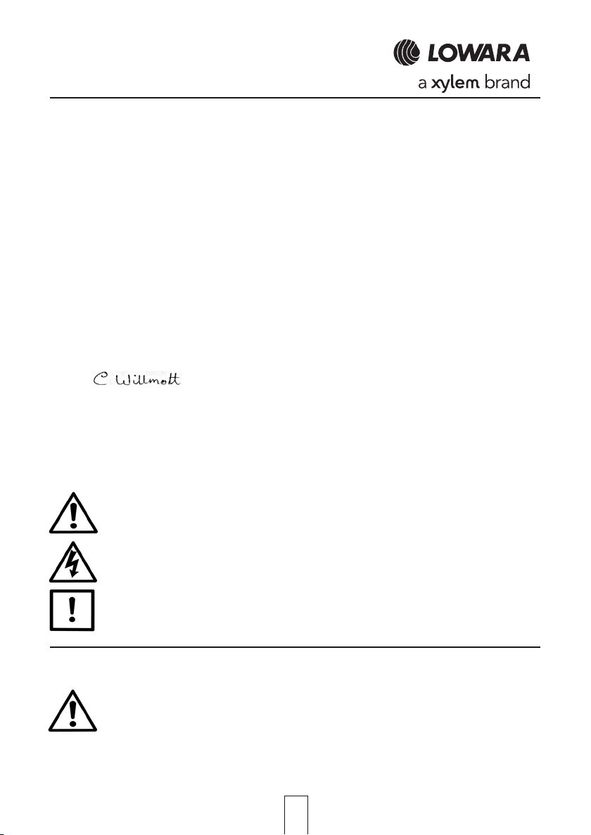
Warning Symbols
Safety instructions where noncompliance would affect safety.
Safety instruction where electrical hazard is involved.
Safety instruction where noncompliance could cause damage to the equipment.
Instruction for safe use
This product has been designed for boosting cold water in potable water installations to the operating conditions
Noise Emissions
This equipment operates at a noise level lower than 70dBA.
shown.
This product should not be installed until this leaflet has been studied carefully.
Handling, transportation and installation of this equipment should only take place with the proper
use of lifting equipment.
This product must be stored in a frost-free dry environment.
1
Page 2

Installation
The domestic booster set is despatched mounted on a wooden pallet and covered in a protective film, it is
recommended that the unit be retained in the protective packaging until the product is to be installed. The unit
maintenance and service. The unit is fitted with adjustable feet that can be adjusted to ensure the unit is level
helping to reduce noise and vibration.
Electrical connections
Never operate this product with the inverter front panel removed.
Wait at least 5 minutes before removing front panel.
It is essential that this equipment is earthed to the building earth system.
Pump operates at 230v 50Hz.
Water supply and system connection
incoming water volume, if this is not the case then a pressure reducing valve should be fitted to reduce the
incoming mains water volume.
Extend the 22mm plastic overflow pipe from the rear of the unit to a position where an overflow will be noticed
and rectified.
Connect the discharge port 22mm compression (right hand rear of cabinet) to the system cold water inlet.
It is advisable to arrange a suitably valved by-pass line including non return valve from the incoming mains
water feed and the system cold fill point to enable the booster set to be bypassed in the advent of power
failure. A drain valve is positioned at the rear of the unit to enable the tank to be drained for cleaning.
Commissioning
the pump discharge pipe by releasing the push fit fitting. This will allow air to escape through the pump when
the tank is filled.
4. Open the water supply to the booster set and let the water tank fill with water until the ball valve closes
5. Thoroughly flush the whole system through to ensure any contaminates that may have entered the
will arrive pre-packaged and wired ready for installation.
This product has been fully run tested at our works under simulated site conditions. The unit
should be thoroughly checked for physical damage that may have been caused during transit.
If the unit is found to have damage it must be reported immediately and should not be installed.
The unit should be sited on level ground in position that will allow adequate room for general
The cable used for the incoming supply must be of adequate size to carry the motor full load
current. This is shown on the duty plate. The supply must provide thermal/short circuit protection, a high sensitivity differential switch (0.03A) is also recommended.
All connections must be made using the appropriate wiring drawings for the equipment being
installed, with particular attention being paid to the supply voltages, shown on duty plate.
The base frame must be earth bonded directly to the building earth system
The power supply wiring should be arranged such that it enters the product through the rear of
the case and then into the appropriate cable gland on the inverter.
Connect the domestic booster water inlet 15mm compression (left side of cabinet) to a suitable
water supply. The water inlet to the ball cock has an internal isolation valve but it is advisable to
fit one external isolation valve for added ease of maintenance. If the pressure available at the
ball valve is below 0.3 bar, a low pressure orifice must be obtained and fitted.
It is the responsibility of the installer to ensure that the overflow is able to keep up with the
1. Ensure the water tank is clean; the pump is in the correct position with the anti-spin bracket
engaged and the drain valve closed. Ensure the by-pass lines (if fitted) are closed.
2. Check the vessel pre-charge, this should be set to 0.2 bar below the system
pressure, Re-charge with Nitrogen or dry air if required. Open vessel isolation valve.
3. With the power supply off, Close the discharge isolation valve and lift the Aquontroller off of
and stops further filling. Check the water level is correct and all joints are sound. Re-connect the Aquon
troller to the pump discharge pipe and open discharge valve, switch power supply on and slightly open
the furthest outlet, once all air has been evacuated close outlet and pump will stop.
system/tank during installation are completely removed.
2
Page 3

Basic Parameter setting
Power the appliance and within 2 seconds the presentation screen will be displayed whilst this screen is
The screen will then change to MOTOR CURRENT. Input motor current, press and hold ENTER until the
screen shows DONE.
The screen will then show SYSTEM PRESSURE input required system set point pressure, press and hold
Enter until the screen shows DONE.
The screen will then show SYSTEM START. Select ON, press ENTER and hold until screen shows DONE,
The screen will then show SAVE & EXIT, press ENTER and hold until screen shows DONE.
All parameters will now be saved and screen will revert to normal window showing system pressure and
Frequency on the top display line and Status on 2nd line (ACTIVE).
Note if the system pressure is low the pump will start immediately.
Open discharge valve and open an out let in the system to help purge air through and out of the system,
close outlet and pump will ramp down and switch off.
Master menu For extended setting details refer to Aquontroller O&M manual
To enter the master menu press and hold (+) (-) (enter) together until extended mode appears
Enter password 66 then press enter for 2 seconds. Press to scroll through the master menu
Check that par 06 is set to 3 sec, 07 set to 3 seconds, 11 is set to 25Hz, 21 is set to 25Hz and 22 set to 1.0 bar
Operation
When a draw off point connected to the system is opened water will be discharged from the vessel, if the
demand continues the system pressure will start to fall until the pump cut in pressure is reached.
The pump will now start and ramp up maintaining the system pressure.
The pump will ramp up and down until demand cesses and the pump will then ramp down and stop.
Lack of water
If the Aquontroller senses a lack of water the pump will be stopped automatically.
The pump will automatically attempt to start 5 times (once every 5 minutes) if water is still not available the
set will attempt to start every 50 minutes for the next 24 hours if water is still not available the set will shut
down completely and a manual reset will be required. See Aquontroller O&M for further details.
Aquontroller display messages
displayed press the + button and hold, the screen will then change to INSTALLATION.
Press and hold the + button and the screen will change to the SETTING DETAILafter a few
seconds this will automatically change and show LANGUAGE press + or – to scroll through
menu and select English by
pressing ENTER and hold until the screen displays DONE.
3
Page 4

Maintenance
Routine check (6 monthly intervals)
1. Check the pump produces the correct pressure.
2. Check that the pump operates without undue noise or vibration.
3. Check the break tank is clean and that the correct water level has been maintained.
5. Check that the earth connections are tight and making good contact.
6. Check that the gas pre charge is at the correct pressure, this should be done by isolating the vessel from
the system and draining water out of the vessel via the isolation valve drain point.
once the water has been discharged, a tyre gauge can be connected to the pre charge valve to display the
vessel pre charge pressure. Recharge as necessary with Nitrogen or dry air.
Any other expansion vessels connected to the system can be checked in the same manner.
General fault finding guide
4. Check that all screws are tight on electrical components.
Fault Possible Cause Remedy
Pump fails to start
Pump fails to stop
Pump switches on and off
quickly
Pump runs but will not
make pressure
Pump overheating Pump partially seized
Break tank overflowing
Pump stops and pressure
drops immediately
Power supply failure
Isolator fuse blown/MCB tripped
Set point set too high
System pressure low due to large
leak in system
Air in system
Vessel pre-charge incorrect
Pump air locked
Commissioning valve left open
Passing too much water
Leaking ball valve
Non-return valve letting by
Non-return valve letting by
Vessel pre-charge incorrect
Reinstate incoming power supply
Replace fuse/reset MCB
Lower set point
Switch unit off until leak is repaired
Purge air from pumps and pipework
Check vessel pre-charge and Charge as
necessary with Nitrogen or dry air
Vent pump
Check commissioning valves are in
correct position.
Check system for leaks
Remove pump and check for sediment
build up or foreign objects
Replace ball valve seal
Replace/clean non-return valve
Replace non-return valve
Check vessel pre-charge and Charge as
necessary with Nitrogen or dry air
Lowara UK Limited
Millwey Rise Industrial Estate, Axminster, Devon EX13 5HU - UK
Tel: 01297 630230 Fax: 01297 630270
e-mail: lowaraukenquiries@xyleminc.com
http://www.lowara.co.uk http://completewatersystems.com
Lowara is a trademark of Xylem Inc. or one of its subsidiaries. © 2011 Xylem, Inc.
Lowara reserve the right to make modifications without prior notice.
cod. UKLIT0092 P05/12
4
 Loading...