

Page 1
Operating manual
pHotoFlex /
pHotoFlex Turb
ba75491d04 07/2006
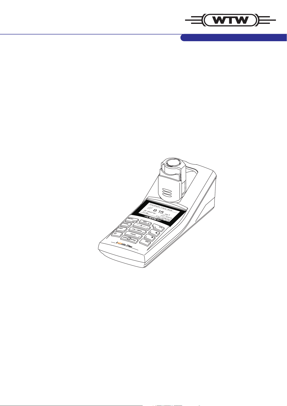
Handheld photometer
Page 2

Accuracy when
going to press
The use of advanced technology and the high quality standard of our
instruments are the result of continuous development. This may result
in differences between this operating manual and your instrument. Also, we cannot guarantee that there are absolutely no errors in this manual. Therefore, we are sure you will understand that we cannot accept
any legal claims resulting from the data, figures or descriptions.
Firmware
Method data
Analysis specifications
Operating manual
Part of the process of consequently improving our products is the
continuous further development of the range of photometric tests
supplied and the meter firmware. All current data for the pHotoFlex /
pHotoFlex Turb can be found on the Internet under http://
www.WTW.com.
You can easily transfer new firmware to your instrument with the aid of
the AK 540/B cable and a PC. More detailed information can be found
in the appendix of the detailed operating manual on the CD-ROM
provided.
Copyright
© 2006, WTW GmbH
Reprinting - even as excerpts - is only allowed with the explicit written
authorization of WTW GmbH, Weilheim.
Printed in Germany.
Page 3

pHotoFlex / pHotoFlex Turb Contents
1 Overview . . . . . . . . . . . . . . . . . . . . . . . . . . . . . . . . . . . . . . 7
1.1 General features . . . . . . . . . . . . . . . . . . . . . . . . . . . . . . . 7
1.2 Keypad . . . . . . . . . . . . . . . . . . . . . . . . . . . . . . . . . . . . . . . 8
1.3 Display . . . . . . . . . . . . . . . . . . . . . . . . . . . . . . . . . . . . . . 10
1.4 Socket field . . . . . . . . . . . . . . . . . . . . . . . . . . . . . . . . . . . 10
1.5 LabStation (optional) . . . . . . . . . . . . . . . . . . . . . . . . . . . 11
2 Safety . . . . . . . . . . . . . . . . . . . . . . . . . . . . . . . . . . . . . . . 13
2.1 Authorized use . . . . . . . . . . . . . . . . . . . . . . . . . . . . . . . . 14
2.2 General safety instructions . . . . . . . . . . . . . . . . . . . . . . . 14
3 Commissioning . . . . . . . . . . . . . . . . . . . . . . . . . . . . . . . 17
3.1 Scope of delivery . . . . . . . . . . . . . . . . . . . . . . . . . . . . . . 17
3.2 Power supply . . . . . . . . . . . . . . . . . . . . . . . . . . . . . . . . . 17
3.3 Connecting the LabStation . . . . . . . . . . . . . . . . . . . . . . . 19
3.4 Initial commissioning . . . . . . . . . . . . . . . . . . . . . . . . . . . 21
4 Operation . . . . . . . . . . . . . . . . . . . . . . . . . . . . . . . . . . . . 23
4.1 Switching on the meter . . . . . . . . . . . . . . . . . . . . . . . . . . 23
4.2 Inserting a cell . . . . . . . . . . . . . . . . . . . . . . . . . . . . . . . . 24
4.3 General operating principles . . . . . . . . . . . . . . . . . . . . . 27
4.3.1 Operating modes . . . . . . . . . . . . . . . . . . . . . . . . 27
4.3.2 Navigation . . . . . . . . . . . . . . . . . . . . . . . . . . . . . 27
4.3.3 Navigation example 1: Setting the language . . . 30
4.3.4 Navigation example 2: Setting the date and time 31
4.3.5 Menu overview . . . . . . . . . . . . . . . . . . . . . . . . . 33
4.4 System settings (System menu) . . . . . . . . . . . . . . . . . . 35
4.4.1 Measured value memory . . . . . . . . . . . . . . . . . . 36
4.4.2 Display . . . . . . . . . . . . . . . . . . . . . . . . . . . . . . . 38
4.4.3 Interface . . . . . . . . . . . . . . . . . . . . . . . . . . . . . . 38
4.4.4 Date/time . . . . . . . . . . . . . . . . . . . . . . . . . . . . . . 39
4.5 Photometry . . . . . . . . . . . . . . . . . . . . . . . . . . . . . . . . . . . 40
4.5.1 General information . . . . . . . . . . . . . . . . . . . . . . 40
4.5.2 Settings for photometric measurements . . . . . . 41
4.5.3 Measuring the concentration . . . . . . . . . . . . . . . 42
4.5.4 Blank value (reagent blank value) . . . . . . . . . . . 43
4.5.5 Measuring the absorbance/transmission . . . . . 45
4.5.6 Zero adjustment . . . . . . . . . . . . . . . . . . . . . . . . 46
4.5.7 Programs . . . . . . . . . . . . . . . . . . . . . . . . . . . . . . 48
4.5.8 Analysis timer . . . . . . . . . . . . . . . . . . . . . . . . . . 49
4.5.9 Timer . . . . . . . . . . . . . . . . . . . . . . . . . . . . . . . . . 49
4.5.10 Measuring diluted samples . . . . . . . . . . . . . . . . 50
4.6 pH value / ORP voltage . . . . . . . . . . . . . . . . . . . . . . . . . 51
4.6.1 General information . . . . . . . . . . . . . . . . . . . . . . 51
4.6.2 Measuring the pH value . . . . . . . . . . . . . . . . . . 52
4.6.3 Measuring the ORP voltage . . . . . . . . . . . . . . . 53
4.6.4 Settings for pH and ORP measurements . . . . . 53
ba75491d04 07/2006
3
Page 4

Contents pHotoFlex / pHotoFlex Turb
4.6.5 Calibration . . . . . . . . . . . . . . . . . . . . . . . . . . . . . 55
4.6.6 Carrying out the TEC and NIST/DIN calibration
procedures . . . . . . . . . . . . . . . . . . . . . . . . . . . . . 58
4.7 Turbidity . . . . . . . . . . . . . . . . . . . . . . . . . . . . . . . . . . . . . 62
4.7.1 General information . . . . . . . . . . . . . . . . . . . . . . 62
4.7.2 Aligning and marking a cell . . . . . . . . . . . . . . . . 62
4.7.3 Measuring turbidity . . . . . . . . . . . . . . . . . . . . . . 63
4.7.4 Calibration . . . . . . . . . . . . . . . . . . . . . . . . . . . . . 65
4.8 Storing . . . . . . . . . . . . . . . . . . . . . . . . . . . . . . . . . . . . . . 68
4.8.1 Storing measurement datsets . . . . . . . . . . . . . . 69
4.8.2 Filtering measurement datsets . . . . . . . . . . . . . 70
4.8.3 Displaying measurement datsets . . . . . . . . . . . . 71
4.8.4 Downloading the measurement datsets to the
RS232
interface . . . . . . . . . . . . . . . . . . . . . . . . . . . . . . . 71
4.8.5 Erasing stored measurement datasets . . . . . . . 72
4.9 Transmitting data (RS 232 interface) . . . . . . . . . . . . . . . 72
4.9.1 Connecting a PC/external printer . . . . . . . . . . . . 72
4.9.2 Configuring the RS232 interface . . . . . . . . . . . . 73
4.9.3 Selecting the output format of datasets . . . . . . . 73
4.9.4 Transmitting data . . . . . . . . . . . . . . . . . . . . . . . . 75
4.10 Reset . . . . . . . . . . . . . . . . . . . . . . . . . . . . . . . . . . . . . . . 76
4.10.1 Resetting the system settings . . . . . . . . . . . . . . 76
4.10.2 Resetting the photometer settings . . . . . . . . . . . 77
4.10.3 Resetting the pH settings . . . . . . . . . . . . . . . . . . 77
4.11 Meter information . . . . . . . . . . . . . . . . . . . . . . . . . . . . . . 78
4.12 Software update . . . . . . . . . . . . . . . . . . . . . . . . . . . . . . . 78
4.13 Administrating user-defined methods . . . . . . . . . . . . . . . 79
4.13.1 Administrating user-defined programs with a
terminal program . . . . . . . . . . . . . . . . . . . . . . . . 80
5 Maintenance, cleaning, disposal . . . . . . . . . . . . . . . . . 83
5.1 Maintenance . . . . . . . . . . . . . . . . . . . . . . . . . . . . . . . . . . 83
5.1.1 Inserting/exchanging the batteries . . . . . . . . . . . 83
5.1.2 Retrofitting the accumulator pack . . . . . . . . . . . 84
5.2 Cleaning . . . . . . . . . . . . . . . . . . . . . . . . . . . . . . . . . . . . . 85
5.2.1 Cleaning the cell shaft . . . . . . . . . . . . . . . . . . . . 85
5.2.2 Cleaning the cells . . . . . . . . . . . . . . . . . . . . . . . 85
5.3 Disposal . . . . . . . . . . . . . . . . . . . . . . . . . . . . . . . . . . . . . 86
6 What to do if... . . . . . . . . . . . . . . . . . . . . . . . . . . . . . . . . 87
6.1 General errors . . . . . . . . . . . . . . . . . . . . . . . . . . . . . . . . . 87
6.2 Photometry . . . . . . . . . . . . . . . . . . . . . . . . . . . . . . . . . . . 88
6.3 pH value / ORP voltage . . . . . . . . . . . . . . . . . . . . . . . . . 88
6.4 Turbidity . . . . . . . . . . . . . . . . . . . . . . . . . . . . . . . . . . . . . 90
7 Technical data . . . . . . . . . . . . . . . . . . . . . . . . . . . . . . . . 91
4
ba75491d04 07/2006
Page 5

pHotoFlex / pHotoFlex Turb Contents
7.1 General data . . . . . . . . . . . . . . . . . . . . . . . . . . . . . . . . . 91
7.1.1 pHotoFlex (Turb) . . . . . . . . . . . . . . . . . . . . . . . . 91
7.1.2 LabStation . . . . . . . . . . . . . . . . . . . . . . . . . . . . . 93
7.2 Photometry . . . . . . . . . . . . . . . . . . . . . . . . . . . . . . . . . . . 93
7.3 pH value / ORP voltage . . . . . . . . . . . . . . . . . . . . . . . . . 94
7.4 Turbidity . . . . . . . . . . . . . . . . . . . . . . . . . . . . . . . . . . . . . 94
8 Accessories, options . . . . . . . . . . . . . . . . . . . . . . . . . . . 95
8.1 WTW accessories . . . . . . . . . . . . . . . . . . . . . . . . . . . . . 95
8.1.1 Connection cable: . . . . . . . . . . . . . . . . . . . . . . . 95
8.2 Optional extensions of the pHotoFlex (Turb) . . . . . . . . . 97
9 Lists . . . . . . . . . . . . . . . . . . . . . . . . . . . . . . . . . . . . . . . . . 99
10 Index . . . . . . . . . . . . . . . . . . . . . . . . . . . . . . . . . . . . . . . 105
Appendix: Firmware update . . . . . . . . . . . . . . . . . . . . . . . 107
ba75491d04 07/2006
5
Page 6

Contents pHotoFlex / pHotoFlex Turb
6
ba75491d04 07/2006
Page 7
pHotoFlex / pHotoFlex Turb Overview
1Overview
1.1 General features
The compact pHotoFlex (Turb) handheld precision photometer enables you to carry out the following measurements quickly and reliably:
! Photometric measurements
– Concentration measurements
– Absorbance measurements
– Transmission measurements
! pH measurements
! Turbidity measurements (pHotoFlex Turb).
The pHotoFlex (Turb) handheld meter provides the maximum degree
of operating comfort, reliability and measuring certainty for all applications.
The proven MultiCal
®
calibration procedure supports you when calibrating for pH measurements and the AutoRead function enables precise pH measurements.
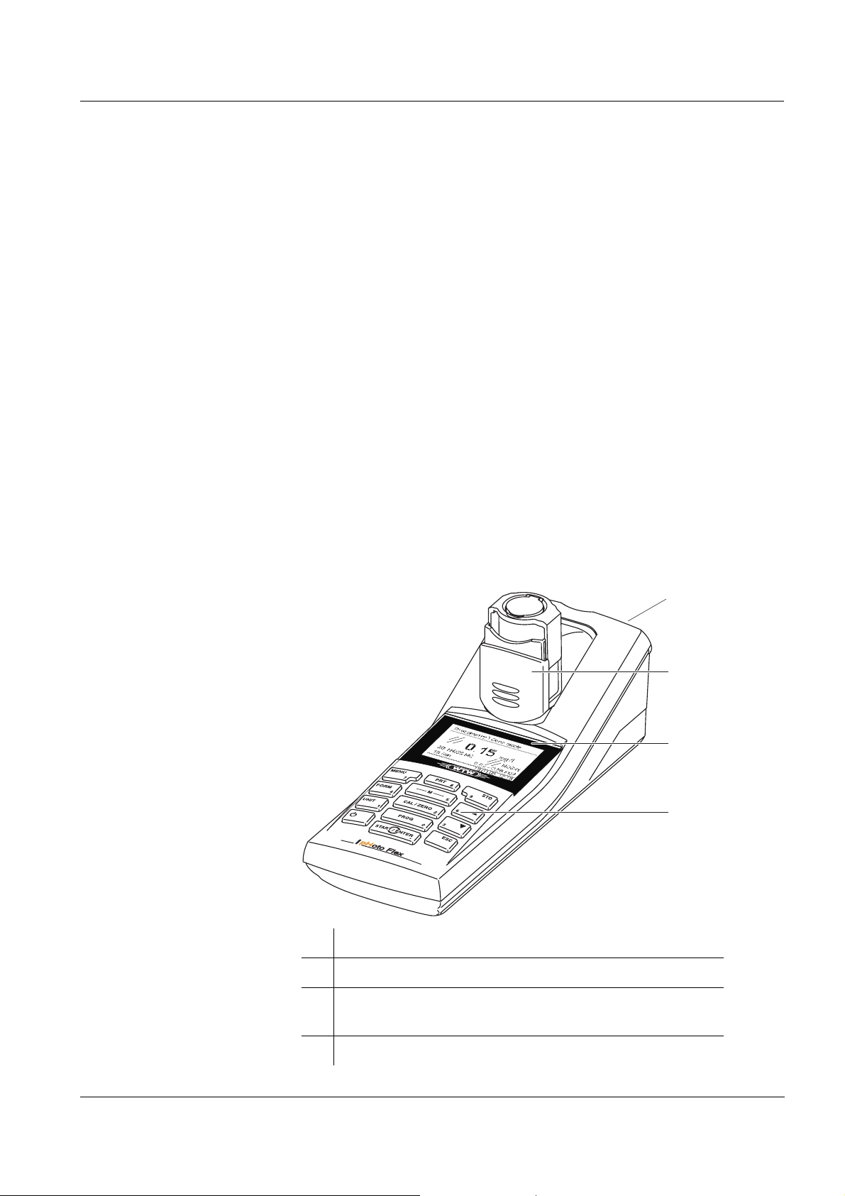
4
3
2
1
ba75491d04 07/2006
1 Keypad
2 Display
3 Cell shaft
(folded out for a 16 mm cell to be inserted)
4 Socket field
7
Page 8
Overview pHotoFlex / pHotoFlex Turb
Note
If you need further information or application notes, you can obtain the
following material from WTW:
! Application reports
! Primers
! Safety datasheets.
You will find information on available literature in the WTW catalog or
via the Internet.
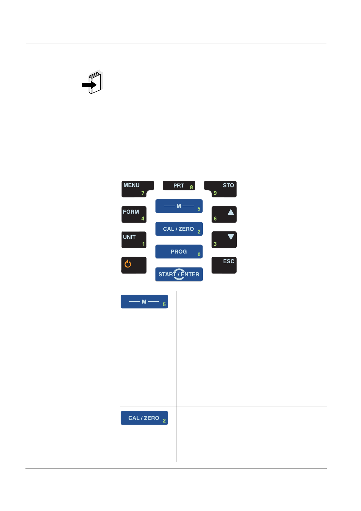
1.2 Keypad
Key functions
.
Select the measuring mode
<M> (long keystroke):
– Photometry
– Turbidity
– pH & ORP
Select the measured parameter within a measuring mode
<M> (short keystroke):
– pH & ORP: pH, ORP
– Photometry:
Concentration, Absorbance, % Transmission
– Turbidity: no measured parameters selectable
Start calibration (measuring modes, pH & ORP,
Turbidity)
Start zero adjustment or blank value measurement using the Photometry \ Adjustment menu
(measuring mode, Photometry)
<CAL/ZERO>
8
ba75491d04 07/2006
Page 9
pHotoFlex / pHotoFlex Turb Overview
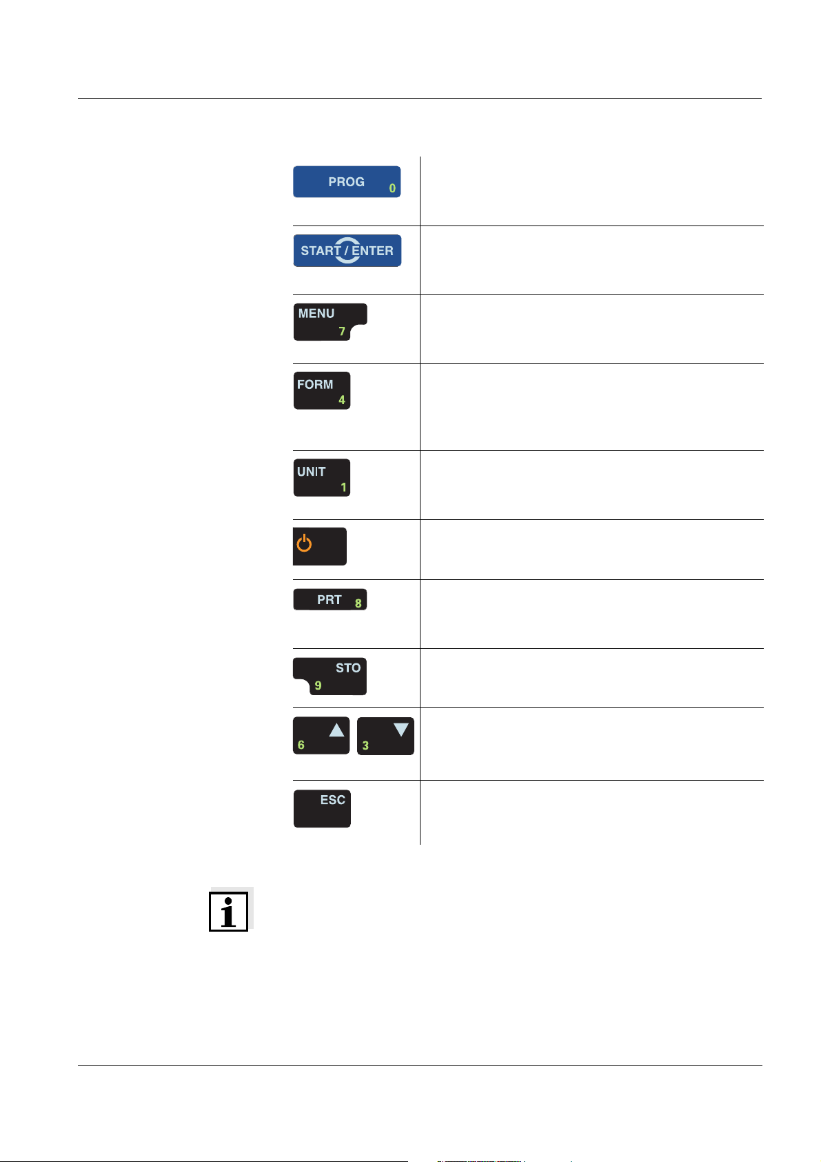
In the Photometry measuring mode: Select a pro-
gram for concentration measurement
<PROG>
Open menus / confirm entries /
start measurement
.
<START/ENTER>
Call up the Configuration menu
(all settings are made here)
<MENU>
In the Photometry measuring mode, measured
parameter, Concentration
:
switch over between available citation forms
<FORM>
In the Photometry measuring mode, measured
parameter, Concentration
:
Switch over between available units <UNIT>
Switch the measuring instrument on/off
<ON/OFF>
PRT
Output display contents to RS232 interface (e.g.
print)
<PRT>
Open the Store menu <STO>,
Quick storing <STO> <STO>
Highlight menu items or selection
Set values
<▲>, <▼>
Switch to the next higher menu level /
cancel input
<ESC>
Note
Keys with an additional number printed on are assigned doubly.
This enables to directly enter numbers in special menus. Thus, you
can, for example, conveniently enter the date and time via the number
keys.
ba75491d04 07/2006
9
Page 10
Overview pHotoFlex / pHotoFlex Turb
1.3 Display
The graphic display shows all information of the current measurement
in the measured value display. The illumination enables to read the display even in the darkness.
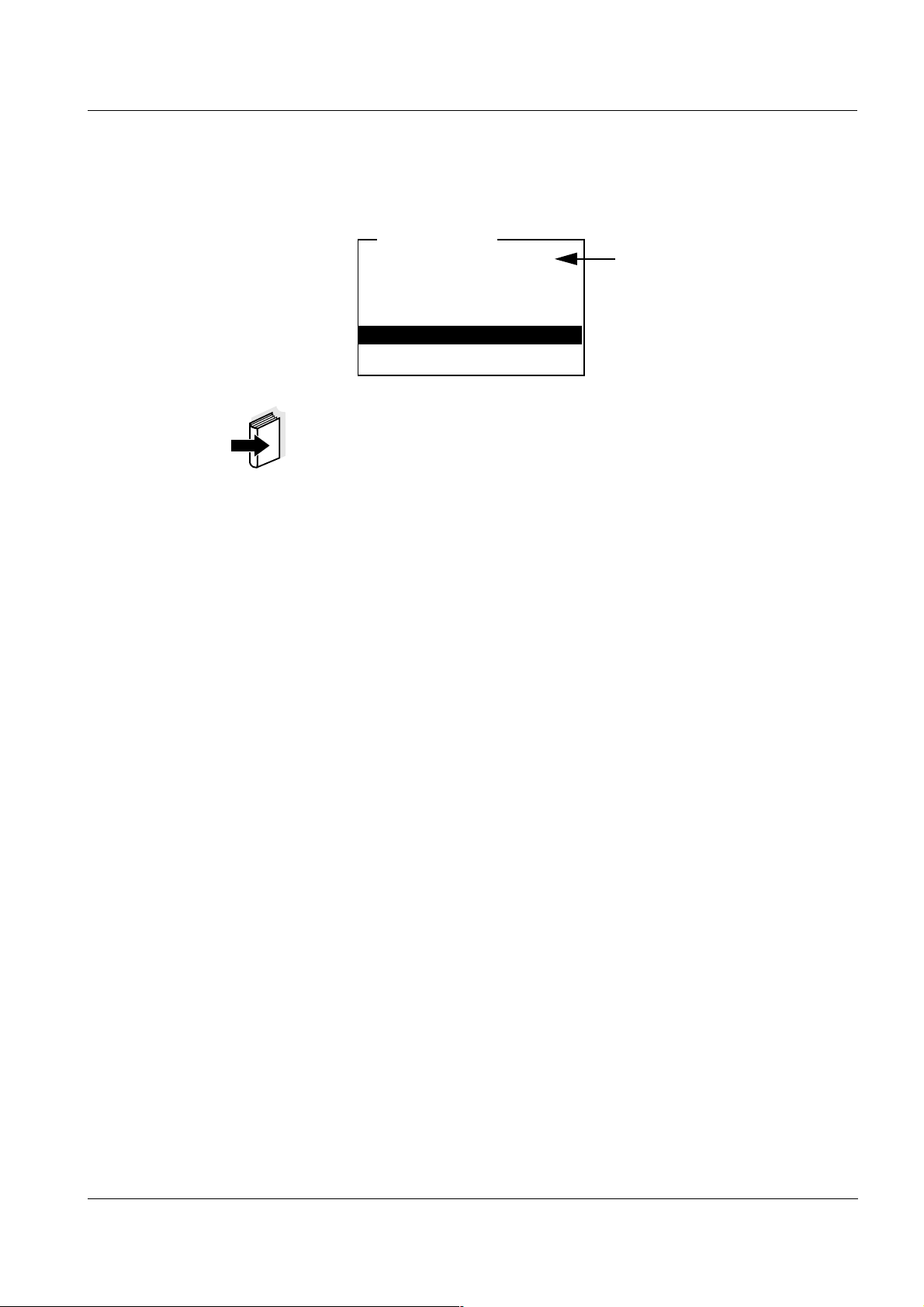
Example
Photometry \ Concentration
1.29
2: A5/25 MC NH4
16 mm 0.20 - 8.00 mg/l
01.02.05 15:12
mg/l
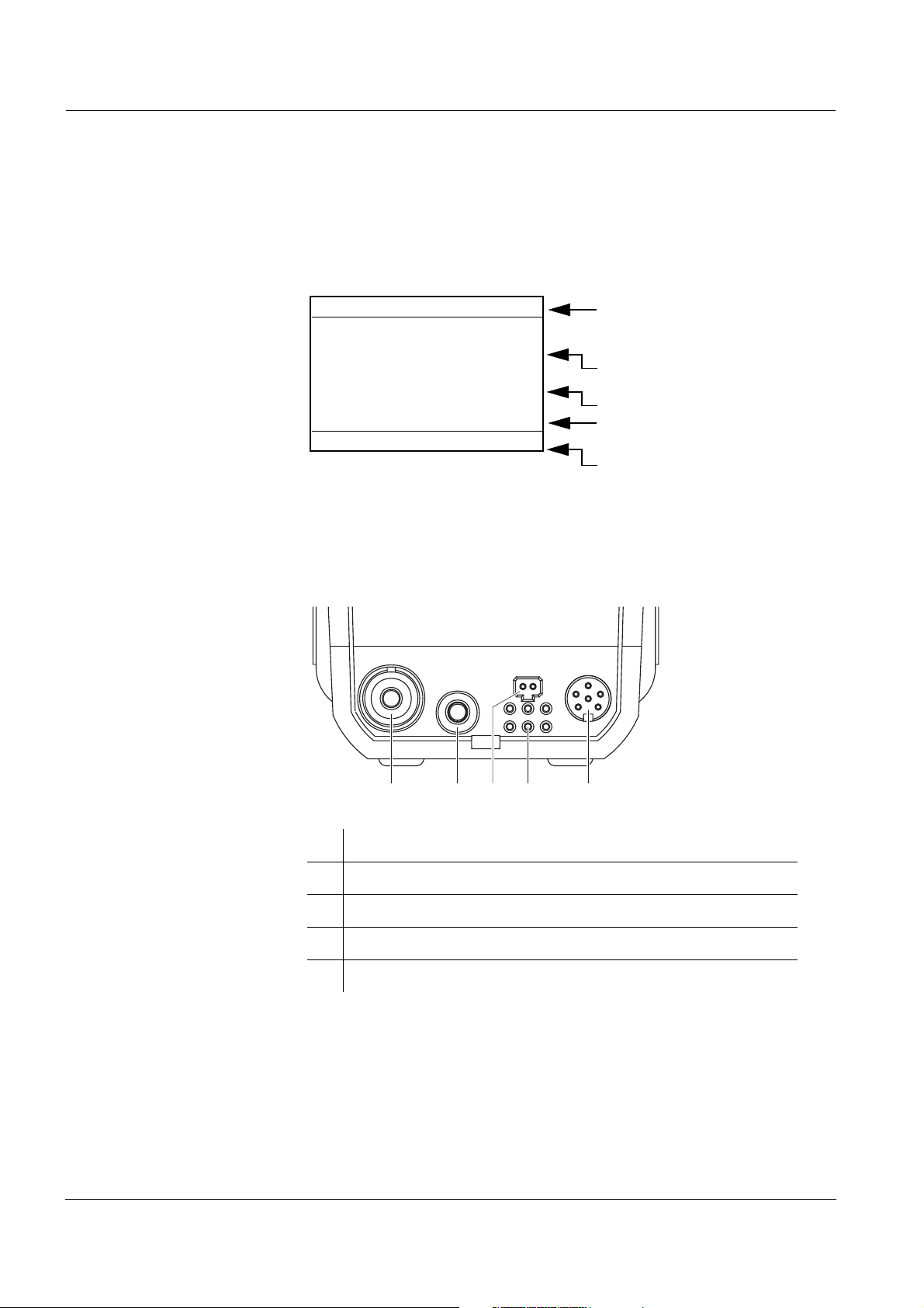
1.4 Socket field
-N
Measuring mode \ measured
parameter
Measured value (with unit)
Program and citation form
Diameter of the cell and
measuring range
Status line with date and time
10
Identifying the
connectors
12345
1 pH electrode
2 pH temperature sensor
3 Power pack
4 Contacts for operation on the LabStation
5 RS232 serial interface
ba75491d04 07/2006
Page 11
pHotoFlex / pHotoFlex Turb Overview
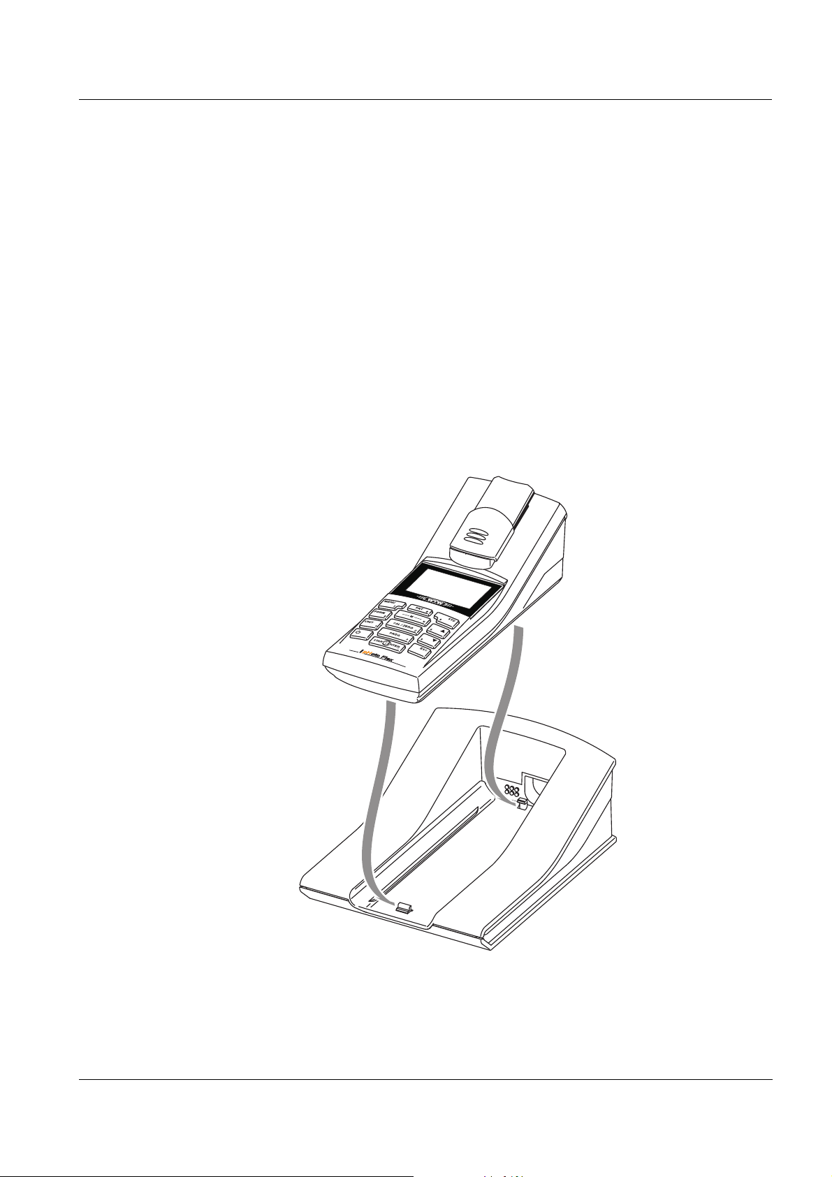
1.5 LabStation (optional)
With the LabStation, which is available as an accessory, you can conveniently use the pHotoFlex (Turb) in the laboratory.
Laboratory operation with the LabStation enables the following additional functions:
! With photometric measurements, the zero measurement is retained
even after switching the pHotoFlex (Turb) off and on again
! You can connect a barcode reader for the simplified calling up of
programs
! The LSdata software serves to easily enter user-defined programs
! Line power operation is possible to save the batteries or accumula-
tor pack
! The accumulator pack in the pHotoFlex (Turb) is automatically
charged as soon as the meter is placed in the LabStation.
ba75491d04 07/2006
LabStation
Fig. 1-1 LabStation
11
Page 12

Overview pHotoFlex / pHotoFlex Turb
12
ba75491d04 07/2006
Page 13
pHotoFlex / pHotoFlex Turb Safety
2 Safety
This operating manual contains basic instructions that you must follow
during the commissioning, operation and maintenance of the meter.
Consequently, all responsible personnel must read this operating manual carefully before working with the meter. The operating manual must
always be available within the vicinity of the meter.
Target group The meter was developed for work in the field and in the laboratory.
We assume that, as a result of their professional training and experience, the operators will know the necessary safety precautions to take
when handling the chemicals of photometric test sets.
The personnel responsible for the commissioning, operation and maintenance must have the necessary qualifications for this work. If the personnel do not have the required skills they have to be instructed.
Furthermore, it must be ensured that the personnel read and completely understand the present operating manual.
Safety instructions The individual chapters of this operating manual use the following safe-
ty instructions to indicate various types of danger:
Caution
indicates instructions that must be followed precisely in order to
avoid the possibility of slight injuries or damage to the instrument
or the environment.
Further notes
Note
indicates notes that draw your attention to special features.
Note
indicates cross-references to other documents, e.g. operating manuals.
ba75491d04 07/2006
13
Page 14

Safety pHotoFlex / pHotoFlex Turb
2.1 Authorized use
This meter is authorized exclusively for carrying out the following measurements in the field and laboratory:
! Analysis of substances in water and aqueous solutions
using round cells
! Concentration measurement
! Absorbance and transmission measurement
! Measurement of pH value and ORP
! Turbidity measurement (pHotoFlex Turb only).
The technical specifications as given in chapter 7 T
ECHNICAL DATA must
be observed. Only the operation and running of the meter according to
the instructions given in this operating manual is authorized. Any other
use is considered to be unauthorized.
2.2 General safety instructions
This instrument is built and inspected according to the relevant guidelines and norms for electronic measuring instruments (see chapter
7T
ECHNICAL DATA).
It left the factory in a safe and secure technical condition.
Opening the photometer or adjustment, maintenance and repair work
must only be performed by specialist personnel authorized by the manufacturer.
The only exceptions to this are the activities described in chapter
5M
AINTENANCE, CLEANING, DISPOSAL. Non-compliance results in the
loss of warranty claims.
Follow the points listed below when operating the photometer:
! Follow the local safety and accident prevention regulations
Function and operating
safety
14
! Observe the enclosed instructions of reagents and accessories
! Observe the regulations when dealing with dangerous substances
! Follow the operating instructions at the workplace
! Use only original spare parts.
The smooth functioning and operational safety of the meter can only be
guaranteed if the generally applicable safety measures and the specific
safety instructions in this operating manual are followed during operation.
ba75491d04 07/2006
Page 15

pHotoFlex / pHotoFlex Turb Safety
The smooth functioning and operational safety of the meter can only be
guaranteed under the environmental conditions that are specified in
chapter 7 T
ECHNICAL DATA.
If the instrument was transported from a cold environment to a warm
environment, the formation of condensate can lead to the faulty functioning of the instrument. In this event, wait until the temperature of the
instrument reaches room temperature before putting the instrument
back into operation.
Safe operation It is the responsibility of the operator to continuously observe the over-
all technical condition (externally recognizable deficits and damage as
well as alterations to the operational behavior) of the meter.
If safe operation is no longer possible, the instrument must be taken out
of service and secured against inadvertent operation!
Safe operation is no longer possible if the meter:
! has been damaged in transport
! has been stored under adverse conditions for a lengthy period of
time
! is visibly damaged
Obligations of the
operator
! no longer operates as described in this manual.
If you are in any doubt, please contact the supplier of the instrument.
Caution
Danger of eye damage by visible and invisible LED radiation. In
the cell shaft there are light emitting diodes (LED) of the 1M class.
Do not look at the radiation using optical instruments.
With normal, authorized use there is no hazard.
The purchaser of this meter must ensure that the following laws and
guidelines are observed when using dangerous substances:
! EEC directives for protective labor legislation
! National protective labor legislation
! Safety regulations
! Safety datasheets of the chemical manufacturers.
ba75491d04 07/2006
15
Page 16

Safety pHotoFlex / pHotoFlex Turb
16
ba75491d04 07/2006
Page 17

pHotoFlex / pHotoFlex Turb Commissioning
3 Commissioning
3.1 Scope of delivery
! Handheld photometer, pHotoFlex Turb or pHotoFlex
! 4 batteries, 1.5 V type AA (in the battery compartment)
! Optional: Accumulator pack and power pack with Euro plug
and exchange plugs for USA, UK, and Australia
! Optional: LabStation
! 1 empty cell 16 mm
! 2 empty cells 28 mm
with label to mark the cell for turbidity measurements
! AMCO
! Microfiber cloth to clean the meter
! Compact operating manual and short operating manual
! CD-ROM with
®
-Clear turbidity standard (pHotoFlex Turb only)
Charging time of the
accumulator pack
– detailed operating manual
– photometry analysis manual with analysis specifications
– software to program user-defined methods
Note
The optional parts of the scope of delivery are available as accessories
(see section 8.1).
3.2 Power supply
You can operate the meter either with batteries, accumulator pack or a
power pack. The power pack supplies the meter with low voltage
(9 V DC). At the same time, the accumulator pack is charged. The accumulator pack is charged even while the meter is switched off.
The LoBat display indicator appears when the batteries or accumulator
pack is nearly discharged.
approx. 36 hours.
Caution
The line voltage at the operating site must lie within the input voltage range of the original power pack (see chapter 7 T
TA).
ECHNICAL DA-
ba75491d04 07/2006
Caution
17
Page 18
Commissioning pHotoFlex / pHotoFlex Turb
Use original power packs only (see chapter 7 TECHNICAL DATA).
Note
The accumulator pack should not be completely discharged. If you do
not operate the instrument for a longer period of time you should charge
the accumulator pack every six months.
Automatic switchoff The meter has an automatic switch-off function in order to save the bat-
teries or accumulator pack (see section 4.4).
Display illumination During operation with batteries or accumulator pack the meter automat-
ically switches off the display illumination if no key is pressed for
30 seconds. The illumination is switched on with the next keystroke
again. The display illumination can also be switched off completely (see
section 4.4.2).
Note
Power pack and accumulator pack are available as an accessory (see
section 8.1).
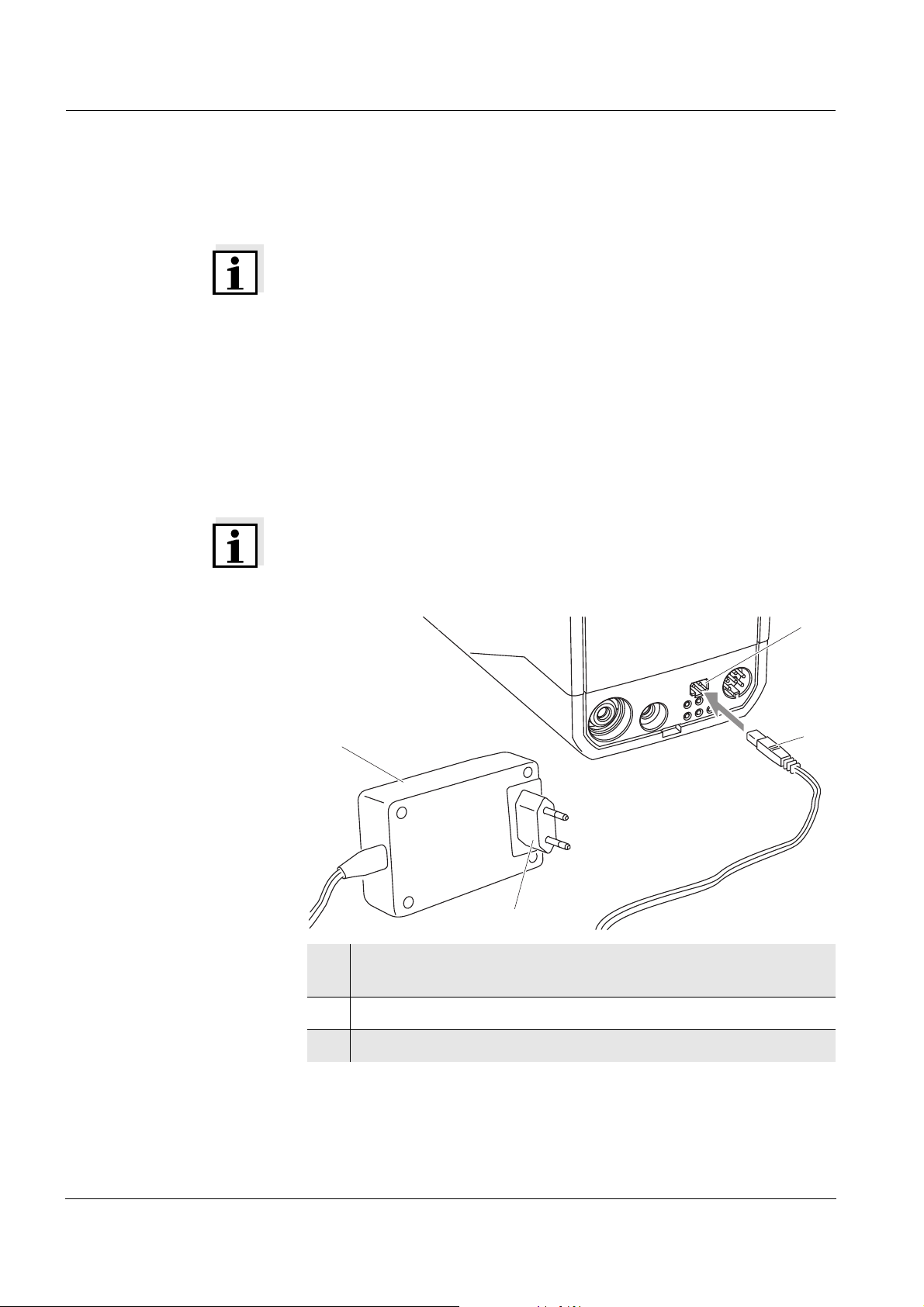
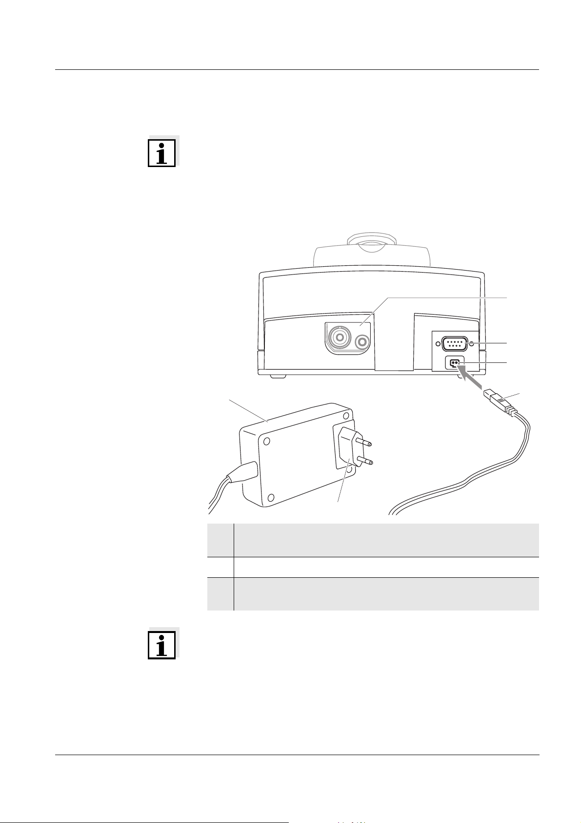
Connecting the power
pack (optional)
4
2
3
1
1 If necessary, replace the Euro plug (1) on the power pack (2)
by the country-specific plug suitable for your country.
2 Connect the plug (3) to the socket (4) of the photometer.
3 Connect the power pack to an easily accessible power socket.
18
ba75491d04 07/2006
Page 19
pHotoFlex / pHotoFlex Turb Commissioning
3.3 Connecting the LabStation
Note
The LabStation is available as an accessory (see section 8.1).
In order to use the functions of the LabStation for operation in the laboratory, connect the LabStation and place the pHotoFlex (Turb) in the
LabStation.
Connecting the LabSta-
tion (optional)
6
5
4
2
3
1
1 If necessary, replace the Euro plug (1) on the power pack (2)
by the country-specific plug suitable for your country.
2 Connect the plug (3) to the socket (4) of the LabStation.
3 Connect a PC, printer or barcode reader to the socket (5) of the
LabStation as necessary.
ba75491d04 07/2006
Note
When the pHotoFlex (Turb) is operated in the LabStation, a barcode
reader can be connected. A barcode reader enables to select program
numbers in a simplified manner.
Recommended barcode readers can be found in section 8.2.
For the interface of your meter, set the same baud rate that is set for
the barcode reader (see section 4.4.3).
The baud rate of the barcode reader is given in the operating manual
of your barcode reader.
19
Page 20
Commissioning pHotoFlex / pHotoFlex Turb
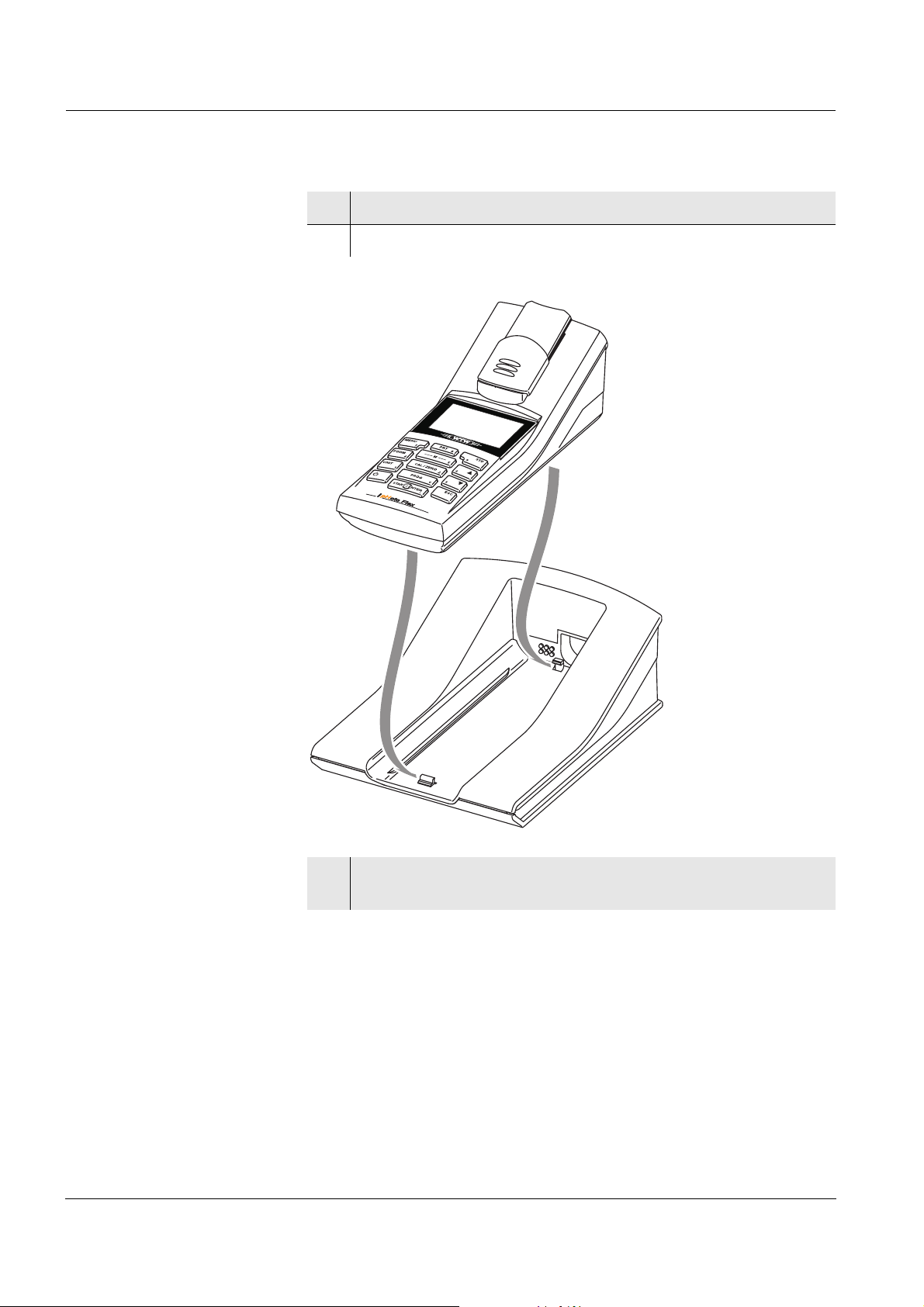
4 Connect the power pack to an easily accessible power socket.
5 Place the pHotoFlex (Turb) in the LabStation.
LabStation
6 Connect a pH electrode to the socket on the pHotoFlex (Turb)
through the cut-out (6) as necessary.
20
ba75491d04 07/2006
Page 21

pHotoFlex / pHotoFlex Turb Commissioning
3.4 Initial commissioning
Perform the following activities:
! For
– accumulator operation: insert the accumulator pack (see
section 5.1.2)
– line power operation and charging the accumulator pack: connect
the power pack (see section 3.2)
– operation with LabStation: connect the LabStation and place the
pHotoFlex (Turb) in the LabStation (see section 3.3)
! Switch on the meter (see section 4.1)
! Set the language as necessary (see section 4.3.3)
! Set the date and time as necessary (see section 4.3.4)
Note
When you set the language, date and time according to the mentioned
sections of this operating manual you will quickly become familiar with
the simple operation of the pHotoFlex (Turb).
ba75491d04 07/2006
21
Page 22

Commissioning pHotoFlex / pHotoFlex Turb
22
ba75491d04 07/2006
Page 23

pHotoFlex / pHotoFlex Turb Operation
4 Operation
4.1 Switching on the meter
Switching on Press the <ON/OFF> key.
For 30 seconds, Start menu appears with a selection of the measuring
modes. The measuring mode last selected is highlighted.
The status line indicates the meter designation and the version number
of the software.
Start
Photometry
Turbidity
pH & ORP
i pHotoFlex V 0.24
After a few seconds, the meter automatically switches to the measuring
mode and measured parameter used last.
The measured value display appears (here, e.g. measuring mode Pho-
tometry).
Photometry \ Concentration
i Select program
with <PROG>
01.02.05 15:12
With <M> (long pressure) change the measuring mode.
With <M> (short pressure) toggle between the different measured parameters in the selected measuring mode.
Switching off Press the <ON/OFF> key.
Automatic switchoff The meter has an automatic switchoff function in order to save the bat-
teries or accumulator pack (see section 4.4). The automatic switchoff
switches the meter off if no key is pressed for an adjustable period.
ba75491d04 07/2006
The automatic switchoff is not active
! if the power is supplied by the power pack (optional),
! if the power is supplied by the LabStation (optional),
! if the Timer or Analysis timer function is on.
23
Page 24
Operation pHotoFlex / pHotoFlex Turb
Display illumination
with battery and accu-
mulator pack operation
During operation with batteries or accumulator pack the meter automatically switches off the display illumination if no key is pressed for
30 seconds. The illumination is switched on again with the next keystroke.
4.2 Inserting a cell
To be able to insert cells in the pHotoFlex (Turb), the cell shaft has to
be prepared to take in a cell.
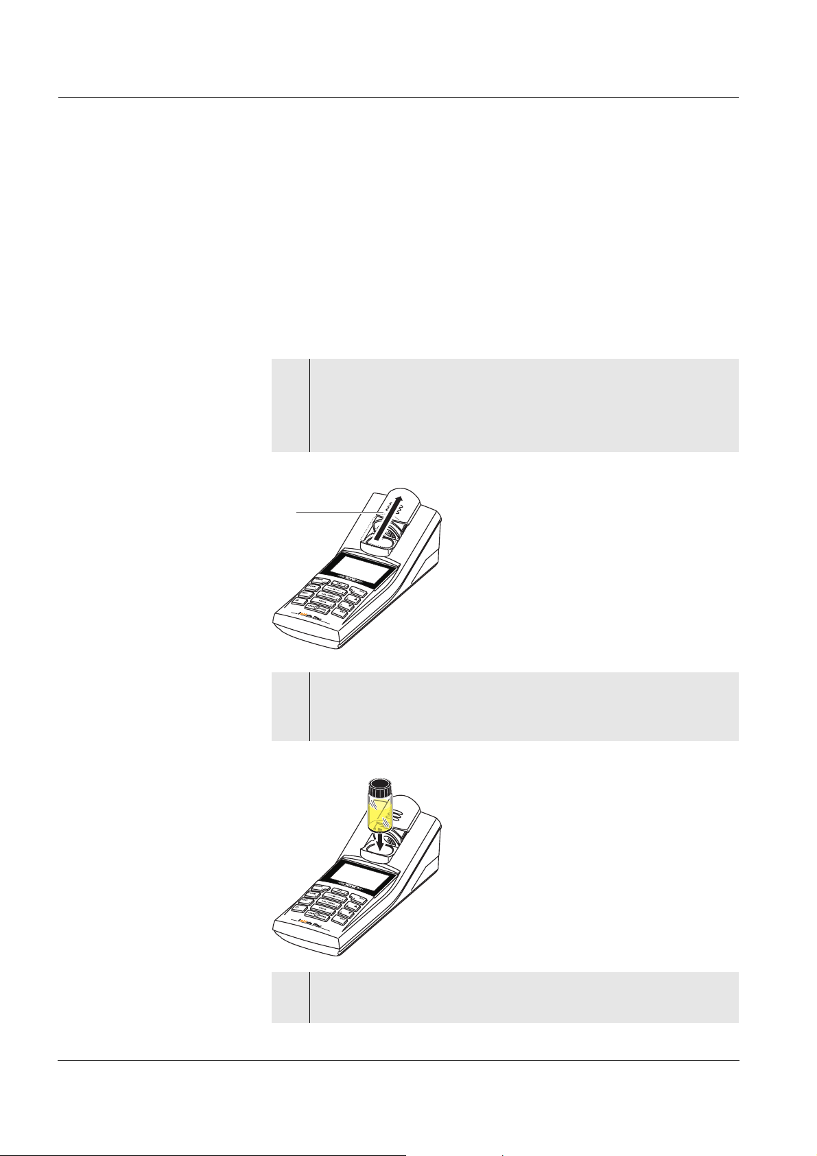
1 Push the dust cover (1) upward.
The cell shaft for 28 mm cells is open.
! Insert a 28 mm cell (see below)
! Insert a 16 mm cell (see page 25)
1
Inserting a 28 mm cell
2 Insert the cell so that it is positioned on the bottom of the cell
shaft.
The cell is ready to be measured.
3 For turbidity measurement:
Align the cell (see section 4.7.2).
24
ba75491d04 07/2006
Page 25
pHotoFlex / pHotoFlex Turb Operation
Inserting a 16 mm cell
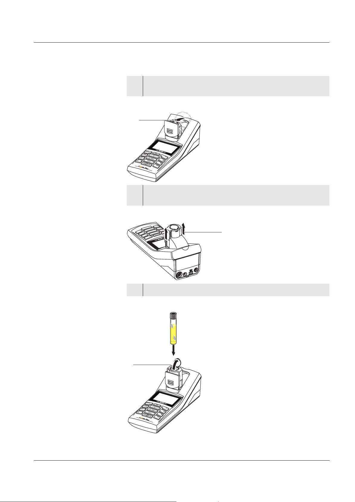
1 Put the fold-out cell shaft (2) in an upright position until it locks
into place.
2
2 Pull up the height adapter (3).
The cell shaft is extended.
3
3 Open the external light cover (4) of the cell shaft.
4
ba75491d04 07/2006
25
Page 26

Operation pHotoFlex / pHotoFlex Turb
4 Insert the 16 mm cell (marking points forward) so that it is po-
sitioned on the bottom of the cell shaft.
5 Close the external light cover (4).
The cell is ready to be measured.
Note
For optimum measurement results, the cell must always be covered by
the external light cover. Otherwise, external light can falsify the measurement result.
26
ba75491d04 07/2006
Page 27

pHotoFlex / pHotoFlex Turb Operation
4.3 General operating principles
This section contains basic information on the operation of the
pHotoFlex (Turb).
Operating elements,
display
Operating modes,
navigation
An overview of the operating elements and the display is given in
section 1.2 and section 1.3.
An overview of the operating modes of the pHotoFlex (Turb) and the
navigation through menus and functions can be found in section 4.3.1
and section 4.3.2.
4.3.1 Operating modes
The instrument has the following operating modes:
! Measurement
The display indicates measurement data in the measured value display
! Calibration
The display indicates a calibration process with calibration information,
or a process to carry out a zero adjustment
! Data transmission
The meter transmits measuring datasets or calibration records to the
serial interface
! Configuration
The display indicates a menu with further menus, settings and functions
4.3.2 Navigation
Measured value display In the measured value display, you can
! select a measuring mode with <M> (long pressure)
! select a measured parameter in the active measuring mode (e. g.
pH <−> mV) with <M> (short pressure)
! open the menu with <MENU>
! switch to the superordinate Start menu with <ESC>.
ba75491d04 07/2006
27
Page 28

Operation pHotoFlex / pHotoFlex Turb
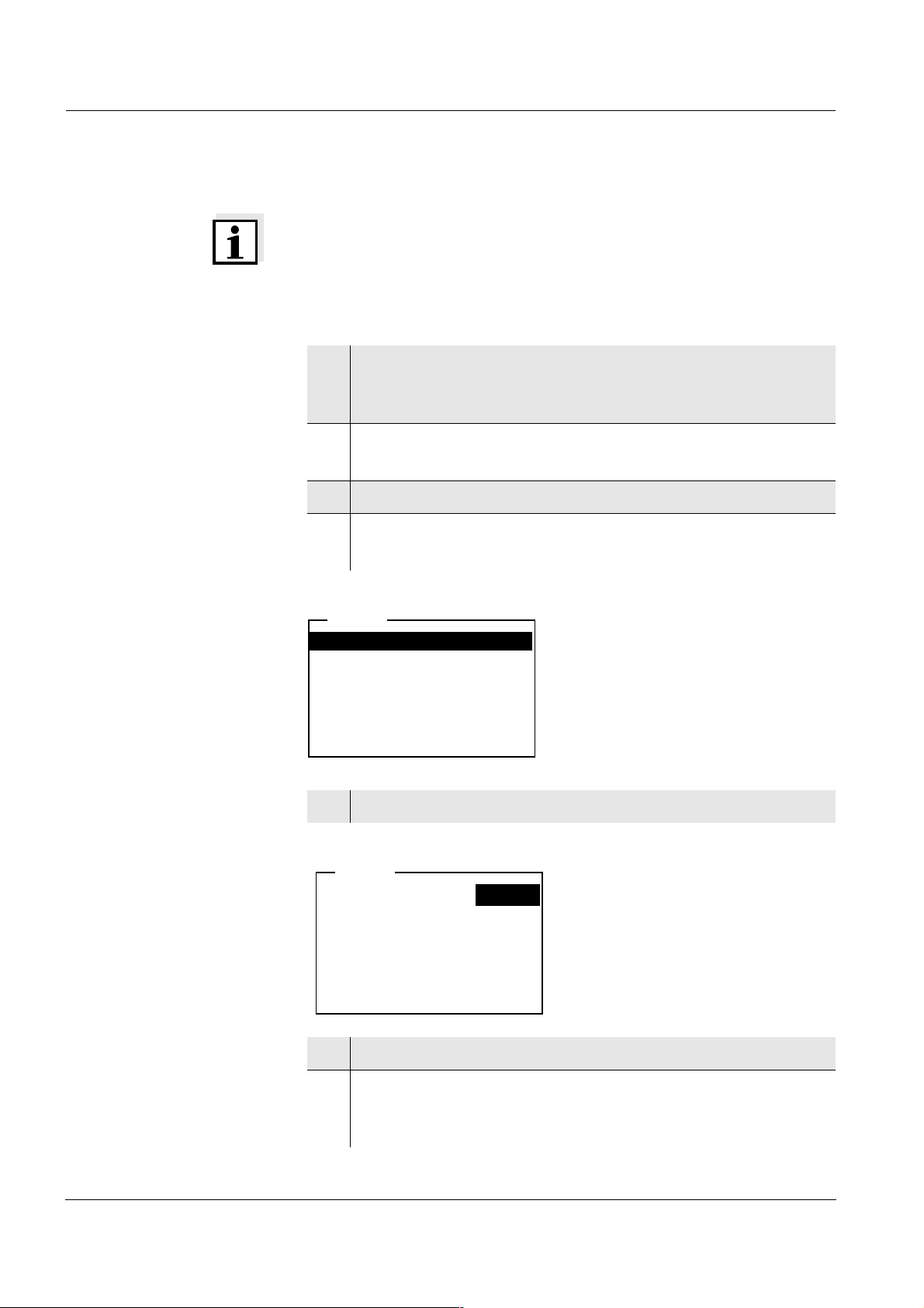
Menus and dialogs The menus for settings and dialogs in courses contain further sub-
menus. The selection is made with the <▲><▼> keys.
The current selection is displayed in reverse video.
! Menus
The name of the menu is displayed at the upper edge of the frame.
Menus are opened by confirming with <START/ENTER>. Example:
Configuration
Photometry
Turbidity
pH & ORP
System
Info
! Settings
Settings are indicated by a colon. The current setting is displayed on
the right-hand side. With <START/ENTER>, the selection of the
possible settings is opened. Subsequently, the setting can be
changed with <▲><▼> and <START/ENTER>.
Example:
System
Language: Deutsch
Beep:
Illumination
Contrast
Temperature unit
Switchoff time
: On
:
:
:
Off
48 %
°C
30 min
! Functions
Functions are designated by the name of the function. They are immediately carried out by confirming with <START/ENTER>.
Example: display the Calibration record function
(in the pH & ORP / Calibration menu).
pH & ORP
Calibration record
Cal. type: AutoCal
TEC
Calibration interval
Unit for slope
:i 2.00 4.01 7.00 10.01
:
:
007 d
mV/pH
28
! Messages
Information or instructions are marked by the i symbol. They can-
not be selected.
ba75491d04 07/2006
Page 29
pHotoFlex / pHotoFlex Turb Operation
Example:
pH & ORP
i Buffer recognition TEC
i Immerse sensor in buffer 1
The i symbol indicates
info texts, e.g.
messages, notes or instructions
Set temperature: 25 °C
Continue
Note
The principles of navigation are explained in the two following sections
by reference of examples:
! Setting the language (section 4.3.3)
! Setting the date and time (section 4.3.4).
ba75491d04 07/2006
29
Page 30
Operation pHotoFlex / pHotoFlex Turb
4.3.3 Navigation example 1: Setting the language
Note
The following example describes in the language of the country how to
set the language. On delivery, English is set as the language in the
pHotoFlex (Turb). During initial commissioning, the language is set in
the menu, Configuration / System / Language.
1 In the measured value display:
Open the Configuration menu with <MENU>.
The instrument is in the configuration mode.
2 Select the System menu with <▲><▼>.
The current selection is displayed in reverse video.
3 Open the System menu with <START/ENTER>.
4 Select the Language menu with <▲><▼>.
The current selection is displayed in reverse video.
System
Language: Deutsch
Store
Display
Reset
Interface
Continue ...
5 Open the setting of the Language with <START/ENTER>.
System
Language:
Store
Display
Reset
Interface
Continue ...
Deutsch
6 Select the required language with <▲><▼>.
30
7 Confirm the setting with <START/ENTER>.
The setting is active. The menu is displayed in the selected language.
ba75491d04 07/2006
Page 31

pHotoFlex / pHotoFlex Turb Operation
8 To make further settings, switch to the next higher menu level
with <ESC>.
or
Switch to the measured value display with <M> (short pres-
sure).
The instrument is in the measurement mode.
4.3.4 Navigation example 2: Setting the date and time
The meter has a clock with a date function. The date and time are indicated in the status line of the measured value display. When storing
measured values and calibrating, the current date and time are automatically stored as well.
Numerals are generally entered via the number keys.
Setting the date, time
and date format
The correct setting of the date and time and date format is important for
the following functions and displays:
! Current date and time
! Calibration date
! Identification of stored measured values.
Therefore, check the time at regular intervals.
Note
After a fall of the supply voltage (empty batteries or accumulator pack),
the date and time are reset to 01.01.2003, 00:00 hours.
The data format can be switched from the display of day, month, year
(dd.mm.yy) to the display of month, day, year (mm/dd/yy or mm.dd.yy).
1 In the measured value display:
Open the Configuration menu with <MENU>.
The instrument is in the configuration mode.
2 Select and confirm the System / Continue ... / Date/time menu
with <▲><▼> and <START/ENTER>.
ba75491d04 07/2006
Date/time
Time:
:
Date
Date format
14:53:40
30.10.03
: dd.mm.yy
31
Page 32

Operation pHotoFlex / pHotoFlex Turb
3 Select and confirm the Time menu with <▲><▼> and
<START/ENTER>.
A display for the entry of numerals with the number keys opens
up.
Time
14:53:40
4 Enter the time using the number keys.
The digit to be changed is displayed underlined.
Note
In the case of wrong entries, you can cancel the procedure with <ESC>.
After canceling with <ESC>, it is possible to enter all digits once again.
The new digits are only taken over by confirming with <START/EN-
TER>.
5 Confirm the setting with <START/ENTER>.
The time is set.
6 Set the current Date as necessary. The setting is made similar-
ly to that of the time.
7 Change the date format as necessary.
8 To make further settings, switch to the next higher menu level
with <ESC>.
or
Switch to the measured value display with <M> (short pres-
sure).
The instrument is in the measurement mode.
32
ba75491d04 07/2006
Page 33

pHotoFlex / pHotoFlex Turb Operation
4.3.5 Menu overview
Photometry Measured parameter Concentration
% Transmission
Absorbance
Programs
Dilution
Analysis timer On
Off
Reset
Turbidity i No settings required.
pH & ORP Measured parameter pH
ORP
Timer
Calibration Calibration
record
Cal. type TEC
Calibration interval
Unit for slope mV/pH
Man. temperature -20 ... +130 °C
Temperature unit °C, °F
Reset
NIST/DIN
1 ... 999 d
%
ba75491d04 07/2006
33
Page 34

Operation pHotoFlex / pHotoFlex Turb
System Language Deutsch
English
Français
Español
Measured value
Display
memory
RS232 download
Data filter Filter
ID
PROG
Date
Delete
i 4 of 1000 occupied
i Filter: No filter
Display Illumination Auto off
On
Off
Contrast 0 ... 100 %
Brightness 0 ... 100 %
Reset
Interface Baud rate 1200, 2400, 4800,
9600, 19200
34
Info
Continue ... /
Date/time
Continue ... /
Switchoff time
Continue ... /
Beep
Output format ASCII
CSV
Time hh:mm:ss
Date
Date format dd.mm.yy
mm.dd.yy
mm/dd/yy
10, 20, 30, 40, 50 min,
1, 2, 3, 4, 5, 10, 15, 20, 24 h
On
Off
ba75491d04 07/2006
Page 35

pHotoFlex / pHotoFlex Turb Operation
4.4 System settings (System menu)
The following instrument features and general functions can be found
in the Configuration / System menu:
! Language selection (Language)
! Memory and database functions (Store)
! Display settings (Display)
! Restore basic settings (Reset)
! Configuration of the interface for PC/printer (Interface)
! Setting the date/time (Date/time)
! Setting the switch-off time (Switchoff time)
! Setting the keyboard sound (Beep)
Settings/functions The settings can be found in the Configuration / System menu.
To switch to the Configuration menu, press the <MENU> key.
Menu item Setting Description
Language Deutsch
English
Select the language (see
section 4.3.3)
Français
Español
Store Display
RS232 download
Memory and database
functions
(see section 4.8.2)
Data filter
Delete
Display Illumination
Contrast
Brightness
Switch on/off the display
illumination (see
section 4.4.2)
Reset - Resets all system settings
to default
(see section 4.10.1)
Interface Baud rate
Output format
Baud rate of the data interface
(see section 4.4.3)
ba75491d04 07/2006
Continue ... /
Date/time
Time
Date
Date format
Settings of time and date
(see section 4.3.4)
35
Page 36

Operation pHotoFlex / pHotoFlex Turb
Menu item Setting Description
Continue ... /
Switchoff time
10, 20, 30, 40,
50 min,
1, 2, 3, 4, 5, 10,
15, 20, 24 h
The automatic switchoff
switches the meter off if
no entry is made for a
specified period of time
(Switchoff time). This
saves the batteries or accumulator pack.
Continue ... /
Beep
On
Off
Switch on/off the beep on
keystroke
4.4.1 Measured value memory
In the Measured value memory menu, you find functions to display and
edit the stored measurement datasets:
! Display the measurement datsets on the screen (Display)
! Download the measurement datsets to the RS232 interface (RS232
download)
! Set up filter rules for the stored measurement datsets (Data filter)
! Erase all stored measurement datsets (Delete)
Settings/functions
! Information on the number of occupied memory locations
The settings can be found in the Configuration / System / Measured val-
ue memory menu.
To switch to the Configuration menu, press the <MENU> key.
Menu item Setting/func-
Description
tion
Display - Displays in pages all mea-
surement datasets that correspond to the filter settings.
Further options:
! Scroll through the
datasets with <▲><▼>.
! Output the displayed
dataset to the interface
with <PRT>.
! Quit the display with
<ESC>.
36
ba75491d04 07/2006
Page 37

pHotoFlex / pHotoFlex Turb Operation
Menu item Setting/func-
Description
tion
RS232 download - Downloads to the interface
all measurement datasets
that correspond to the filter
settings. The download is
ordered according to the
date and time.
The process can take several minutes. To terminate the
process prematurely, press
<ESC>.
Data filter see
section 4.8.2
Allows to set filter criteria in
order to display and download datasets to the interface.
Delete - Erases the entire contents
of the measuring data memory, independent of the filter
settings.
Note:
All calibration data remains
stored when performing this
action.
All details on the subjects of memory and stored data is found in
section 4.8.2.
ba75491d04 07/2006
37
Page 38

Operation pHotoFlex / pHotoFlex Turb
4.4.2 Display
In the Configuration / System / Display menu, you set the display fea-
tures:
! Switching on/off the display illumination (Illumination)
! Display contrast (Contrast)
The settings can be found in the Configuration / System / Display menu.
To switch to the Configuration menu, press the <MENU> key.
Settings
Menu item Setting Description
Illumination Auto off The display illumination is
automatically switched off if
no key has been pressed
for 30 seconds.
On
Off
Switches the display illumination on or off permanently (see section 4.5.8)
Contrast 0 ... 100 % Changes the display con-
trast
Brightness 0 ... 100 % Changes the display bright-
ness
4.4.3 Interface
In the Interface menu, you set the features of the interface:
! Transmission speed (Baud rate)
! Output format (Output format)
38
Settings
The settings can be found in the Configuration / System / Interface
menu.
To switch to the Configuration menu, press the <MENU> key.
Menu item Setting Description
Baud rate 1200, 2400,
4800, 9600,
Baud rate of the data
interface
19200
Output format ASCII
CSV
Output format for data
transmission
For details, see section 4.9
ba75491d04 07/2006
Page 39

pHotoFlex / pHotoFlex Turb Operation
4.4.4 Date/time
In the Configuration / System / Continue ... / Date/time menu, you set
the system clock:
! Current time (Time)
! Current date (Date)
! Format of the date display (Date format)
The settings can be found in the Configuration / System / Continue ...
Date/time menu.
To switch to the Configuration menu, press the <MENU> key.
Settings
Menu item Setting Description
Time hh:mm:ss Enter the time with the
number keys
Date Enter the date with the
number keys
Date format dd.mm.yy
Settings of time and date.
mm.dd.yy
mm/dd/yy
ba75491d04 07/2006
39
Page 40

Operation pHotoFlex / pHotoFlex Turb
4.5 Photometry
4.5.1 General information
Photometric measurements serve to determine chemical substances in
liquid samples. For this determination, the substance to be determined
has to be present in a form that is suitable for photometric measurement. At the same time, possible disturbing factors have to be excluded.
Before measurement, the sample has to be pretreated in order to bring
the substance to be determined into the form that is suitable for measurement and at the same time exclude disturbing factors.
Pretreatment of the sample is described in the analysis specification.
In a simple case, pretreatment can be to dissolve a solid substance in
water; it can, however, also include chemical conversions, e. g. a digestion.
The chemicals required in the analysis specification are available as
test sets.
Note
Suitable analysis specifications for test sets can be found in the photometry analysis manual (on CD-ROM).
There you will also find further instructions on handling chemicals and
on how to proceed when applying the analysis specifications.
Methods and the corresponding method data for many test sets are
stored as programs
in the pHotoFlex (Turb). A program number is as-
signed to each program.
By entering the program number or by using a barcode reader the
stored method data is loaded.
You can look up an overview of the available methods in the photometry analysis manual and display it on the screen of the pHotoFlex (Turb)
(see section 4.5.7).
You can measure the following parameters with the pHotoFlex (Turb):
! Concentration [mg/l]
! % Transmission []
40
! Absorbance []
ba75491d04 07/2006
Page 41

pHotoFlex / pHotoFlex Turb Operation
Preparatory activities Perform the following preparatory activities when you want to measure:
1 Clean the cells before filling them with sample and also before
measuring as necessary (see section 5.2.2).
The cells must be absolutely clean and free of scratches.
2 For measurement, place the pHotoFlex (Turb) on a horizontal
surface.
4.5.2 Settings for photometric measurements
For photometric measurements, the following settings are available in
the Configuration / Photometry menu:
! Setting the measured parameter
! Displaying a list of all programs
! Setting the dilution factor
Settings
! Switching on or off the analysis timer
! Resetting the settings for photometric measurements
The settings can be found in the Configuration / Photometry menu.
To switch to the Configuration menu, press the <MENU> key.
Menu item Setting Description
Measured parameter
Concentration
% Transmission
Absorbance
Measured parameters in
the Photometry measuring
mode
Programs Display all programs with
the corresponding program data (see
section 4.5.7).
Dilution Set the dilution factor (see
section 4.5.10)
Analysis timer On
Off
Switch on/off the analysis
timer (see section 4.5.8)
Reset Reset all settings for the
Photometry measuring
mode (see section 4.10.3)
ba75491d04 07/2006
41
Page 42

Operation pHotoFlex / pHotoFlex Turb
4.5.3 Measuring the concentration
1 Press the <M> key (long pressure) repeatedly until the Pho-
tometry measuring mode is selected.
2 Press the <M> key (short pressure) repeatedly until the mea-
sured variable, Konzentration is selected.
First concentration measurement with the pHotoFlex (Turb)
Photometry \ Concentration
i Select program
with <PROG>
01.02.05 15:12
Second and all further
concentration measurements
Photometry \ Concentration
i Select program
with <PROG>
or with ▲
1: A5/25 MC NH4-N
16 mm 0.20 - 6.51 mg/l
▼
01.02.05 15:12
Note
From the second concentration measurement, the data of the program
last used is automatically displayed here.
With <▲><▼> you can quickly switch between the ten programs last
used.
To select a program, you can also read in the program number of an
analysis specification with a barcode reader (see section 8.2). The following step 3 is then skipped. You can directly start measurement.
The program number of the test is given in the analysis specification,
on the list of available programs and on the packing of some tests (under the barcode).
42
3 Open the Program number display with <PROG>,
enter the required program number with the number keys and
confirm with <START/ENTER>.
or (from the second concentration measurement):
Select a program out of the last ten programs with <▲><▼>.
The program data is displayed.
Note
If a program number is selected that requires a measured blank value,
the menu automatically guides to the blank value measurement.
ba75491d04 07/2006
Page 43

pHotoFlex / pHotoFlex Turb Operation
Photometry \ Concentration
i Insert sample
i Start measurement
with <START>
1: A5/25 MC NH4-N
16 mm 0.20 - 6.51 mg/l
01.02.05 15:12
4 Insert the cell (see section 4.2).
5 Start the measurement with <START/ENTER>.
Measurement is started. The result is displayed.
Photometry \ Concentration
[BV]
A blank value measured by
the user is used
0.74 mg/l
1: A5/25 MC NH4-N
16 mm 0.20 - 6.51 mg/l
01.02.05 15:12
4.5.4 Blank value (reagent blank value)
A blank value is required for every concentration measurement.
For some programs (methods) for concentration measurement, the
blank values are already stored in the photometer. They are used automatically. For all other programs, the blank value has to be determined separately before the first measurement.
Each stored reagent blank value can be replaced by a blank value determined by the user.
Note
You will find more information on blank values in the photometry analysis manual.
A blank value is always stored for the program that has just been called
up. It remains stored until it is erased (menu item, Delete blank value)
or overwritten.
The Reset function erases all blank values measured by the user and
restores the blank values stored in the factory.
ba75491d04 07/2006
If a blank value measured by the user is stored for a program, this blank
value is used for measurement. The usage of the blank value measured by the user is documented and also indicated in the measured
value display.
43
Page 44

Operation pHotoFlex / pHotoFlex Turb
Measuring the blank
value
1 Press the <M> key (long pressure) repeatedly until the Pho-
tometry measuring mode is selected.
2 Press the <M> key (short pressure) repeatedly until the mea-
sured variable, Concentration is selected.
3 Select a program with <PROG> as necessary.
Note
The following measurement of the blank value applies only to the selected program. If no program is selected, the message i No program
selected. appears on the display.
4 Open the adjustment menu with <CAL/ZERO>.
Photometry \ Adjustment
Zero adjust.
Measure blank value
Delete blank value
5 Using <▲><▼> and <START/ENTER>, select and start the
Measure blank value function.
The menu-guided blank value measurement starts.
Follow the instructions on the display.
Measure blank value
i 2: A5/25 MC
Cell = 16 mm
i
i Insert blank sample
Start measurement
6 Insert a cell with blank sample (see section 4.2).
7 Start the measurement of the blank value with <START/EN-
TER>.
After measuring, the result of the blank value measurement is
displayed and stored.
The result is displayed as i Blank value measurement suc-
cessful! or i Blank value measurement erroneous!
44
ba75491d04 07/2006
Page 45

pHotoFlex / pHotoFlex Turb Operation
Measure blank value
i 2: A5/25 MC
i Cell = 16 mm
i Absorbance = 0.301
i Blank value mea-
surement
successful!
8 Confirm the result with <START/ENTER>.
The blank value measurement is completed.
The meter is ready to measure.
or:
Discard the result with <ESC>.
Subsequently, carry out a new blank value measurement.
4.5.5 Measuring the absorbance/transmission
Note
The transmission measurement is not described separately in the following example as it operates in exactly the same way as the absorbance measurement. The result of the measurement is displayed in %
Transmission.
1 Press the <M> key (long pressure) repeatedly until the Pho-
tometry measuring mode is selected.
2 Press the <M> key (short pressure) repeatedly until the mea-
sured variable, Absorbance or % Transmission is selected.
Photometry \ Absorbance
i Select cell
with
16 mm 610 nm
▲ ▼
01.02.05 15:12
ba75491d04 07/2006
3 Select the cell diameter with <▲><▼> and confirm with
<START/ENTER>.
4 Select the wavelength with <▲><▼> and confirm with
<START/ENTER>.
45
Page 46

Operation pHotoFlex / pHotoFlex Turb
Photometry \ Absorbance
i Insert sample
i Start measurement
with <START>
16 mm 610 nm
01.02.05 15:12
5 Clean the cell (see section 5.2.2).
6 Insert the cell (see section 4.2).
7 Start the measurement with <START/ENTER>.
The measurement result is displayed when the measurement
is finished.
Photometry \ Absorbance
0.532
16 mm 610 nm
01.02.05 15:12
4.5.6 Zero adjustment
The zero adjustment, i. e. measuring and storing the absorbance of a
cell filled with water, is necessary after the meter is switched on.
Additionally, we recommend to carry out a zero adjustment if the ambient temperature has changed.
Only perform the zero adjustment against distilled water in an optically
perfect cell. The zero adjustment must be performed separately for
each cell type.
1 Press the <M> key (long pressure) repeatedly until the Pho-
tometry measuring mode is selected.
46
2 Press the <M> key (short pressure) repeatedly until the mea-
sured variable, Concentration is selected.
3 Press the <CAL/ZERO> key.
The menu for adjustment measurements opens up.
ba75491d04 07/2006
Page 47

pHotoFlex / pHotoFlex Turb Operation
Photometry \ Adjustment
Zero adjust.
Measure blank value
Delete blank value
4 Using <▲><▼> and <START/ENTER>, select and start the
Zero adjust. function.
The menu-guided zero adjustment starts.
Follow the instructions on the display.
Zero adjust.
i Insert zero
cell (dist. water)
Cell 16 mm
Start measurement
5 Insert the cell (see section 4.2)
6 Set another cell with <▲><▼> and <START/ENTER> as nec-
essary.
7 Start the measurement of the zero adjustment with <START/
ENTER>.
After measuring, the result of the zero adjustment is displayed
and stored.
i Zero adjust. successful! (successful zero adjustment) or
i Calibration error! (zero adjustment not successful)
is displayed as the result.
The zero adjustment is completed.
Note
If i Calibration error! was displayed as the calibration result, a note au-
tomatically reminds you of another zero adjustment before the next
measurement.
Measuring is not possible without a valid zero adjustment.
ba75491d04 07/2006
8 Confirm the result with <START/ENTER>.
The zero adjustment is completed.
The meter is ready to measure.
47
Page 48

Operation pHotoFlex / pHotoFlex Turb
4.5.7 Programs
Displaying program
data
You can view the most important data of all methods.
The method data is ordered according to the program number.
1 Open the Configuration / Photometry / Programs menu.
The display shows the most important data of the selected program.
Programs
1: A5/25 MC
0.20 - 8.00 mg/l
NH4-N
16 mm
i Scroll with
▲ ▼
Program number, test, code
Measuring range with unit
Citation form
Diameter of the cell
Note
This data is also to be found in the photometry analysis manual in the
overview of the test sets and in the individual analysis specifications for
the test sets.
Updating programs Under http://www.WTW.com on the Internet, you can always find the
latest software version with the newest programs and method data for
your pHotoFlex (Turb) (see A
PPENDIX: FIRMWARE UPDATE).
User-defined programs User-defined programs (methods) can be stored under program num-
bers between 900 and 999. You can store up to 100 user-defined programs (see section 4.13).
48
ba75491d04 07/2006
Page 49

pHotoFlex / pHotoFlex Turb Operation
4.5.8 Analysis timer
Measuring according to analysis specifications often means there are
waiting periods between the individual steps.
These waiting periods (time intervals) are stored in the instrument with
the program data for each program. The active Analysis timer function
automatically reminds you to observe these time intervals by means of
the menu guidance.
If you want to manually enter time intervals, use the Timer function (see
section 4.5.9).
The Analysis timer with the required time interval is automatically displayed at the due point.
Start the Analysis timer with the <START/ENTER> key.
It is not possible to shorten the time intervall.
An acoustic signal sounds when the adjusted time interval has expired.
The Analysis timer function is switched on or off in the Configuration /
Photometry/Analysis timer menu.
This setting generally applies to all measurements with methods according to analysis specification.
4.5.9 Timer
When measuring according to analysis specifications, waiting periods
often have to be kept between individual steps of the method.
With the Timer function you manually set a time interval.
If you want to be automatically reminded of the given time interval, use
the Analysis timer function (see section 4.5.8).
The timer is displayed in the measured value display. It always displays
the remaining time of the adjusted time interval.
When the adjusted time interval has expired, the timer indicates
00:00:00 and an acoustic signal sounds.
The Timer function is started in the Configuration / Timer menu by en-
tering a time interval.
ba75491d04 07/2006
49
Page 50

Operation pHotoFlex / pHotoFlex Turb
4.5.10 Measuring diluted samples
If the concentration of a test sample exceeds the measuring range of a
method, you can dilute the sample by a factor 1 ... 99 so that the concentration of the diluted test sample is within the measuring range of
the method (see photometry analysis manual). Thus a valid measurement is possible.
After entering the factor for the dilution the meter converts the concentration to that of the undiluted sample.
The display then indicates the measured value of the undiluted sample.
Entering the factor of
the dilution
1 Select the program for which a dilution factor is to be entered.
2 Open the Configuration / Photometry / Dilution menu.
The current factor of the dilution is displayed.
Dilution
Water + sample 0 + 1
i PROG 1
3 Open the display for the entry of numerals with <START/EN-
TER>.
4 Enter the factor of the dilution with the number keys.
The factor has to be a whole number between 0 ... 99.
5 Confirm the factor with <START/ENTER>.
6 Exit the Dilution menu with <ESC>.
For the following measurements with the selected program, the
concentration of the undiluted sampled is displayed as the
measurement result.
50
The entered dilution factor is only valid for the selected program. The
dilution factor is erased if:
! the photometer is switched off
! a different program number is selected
! the factor 0 is entered in the Dilution menu.
If a dilution factor is active, it is indicated on the display during measurement in the form [x + 1].
ba75491d04 07/2006
Page 51

pHotoFlex / pHotoFlex Turb Operation
4.6 pH value / ORP voltage
4.6.1 General information
You can measure the following variables:
! pH value [ ]
! ORP [mV]
Caution
When connecting an earthed PC/printer, measurements cannot be
performed in earthed media as incorrect values would result. The
RS232 interface is not galvanically isolated.
Temperature
measurement
For reproducible pH measurements, it is essential to measure the temperature of the test sample.
You have the following possibilities for measuring the temperature:
! Automatic measurement of the temperature by a temperature sen-
sor (NTC30 or Pt 1000) integrated in electrode.
! Manual determination and input of the temperature.
The meter recognizes whether a suitable electrode is connected and
automatically switches on the temperature measurement.
The display of the temperature indicates the active temperature measuring mode:
Temperature
sensor
Resolution of the
temp. display
Temperature of the test
sample
yes 0.1 °C automatic measurement
-1°C manual measurement
and entry
Preparatory activities Perform the following preparatory activities when you want to measure:
ba75491d04 07/2006
1 Connect a pH or ORP electrode to the meter.
2 Press the <M> key (long pressure) repeatedly until the pH &
ORP measuring mode is selected.
3 Press the <M> key (short pressure) repeatedly until the mea-
sured parameter, pH or ORP is selected.
4 Adjust the temperature of the solutions and measure the cur-
rent temperature if the measurement is made without a temperature sensor.
5 Calibrate or check the meter with the electrode.
51
Page 52

Operation pHotoFlex / pHotoFlex Turb
4.6.2 Measuring the pH value
1 Perform the preparatory activities according to section 4.6.1.
2 Immerse the pH electrode in the test sample.
AutoRead
(Drift control)
Criteria With identical measurement conditions, the following applies:
pH & ORP
\
pH
6.94
25.0
[AR]
3 Press the <M> key (short pressure) repeatedly until the mea-
sured variable, pH is selected.
The AutoRead function (drift control) continually checks the stability of
the measurement signal. The stability has a considerable impact on the
reproducibility of measured values. The display of the measured parameter flashes until a stable measured value is available.
Measured
parameter
pH value Better than 0.01 > 30 seconds
°C
01.02.05 15:12
Reproducibility Response time
52
ba75491d04 07/2006
Page 53

pHotoFlex / pHotoFlex Turb Operation
4.6.3 Measuring the ORP voltage
Note
ORP electrodes are not calibrated. However, you can check ORP electrodes using a test solution.
1 Perform the preparatory activities according to section 4.6.1.
2 Submerse the ORP electrode in the sample.
pH & ORP
[AR]
AutoRead
(drift control)
Criteria With identical measurement conditions, the following applies:
The AutoRead function (drift control) continually checks the stability of
the measurement signal. The stability has a considerable impact on the
reproducibility of measured values. The display of the measured parameter flashes until a stable measured value is available.
Measured
parameter
ORP voltage better than 1 mV > 30 seconds
\
ORP
157
25.0
3 Press the <M> key (short pressure) repeatedly until the mea-
sured parameter, ORP is selected.
mV
°C
01.02.05 15:12
Reproducibility Response time
Overview For pH and ORP measurements, the following settings are available in
ba75491d04 07/2006
4.6.4 Settings for pH and ORP measurements
the Configuration / pH & ORP menu:
! Measured parameter
! Calibration record (display, print)
! Selecting the calibration type
! Entering the Calibration interval
! Selecting the Unit for slope
! Selecting the Temperature unit
! Reset
53
Page 54

Operation pHotoFlex / pHotoFlex Turb
Settings/functions The settings can be found in the Configuration / pH & ORP menu.
To switch to the Configuration menu, press the <MENU> key.
Menu item Possible
setting
Measured parameter pH & ORP
mV
Calibration /
- Displays the calibration
Calibration record
Calibration /
Cal. type
Calibration /
TEC
NIST/DIN
1 ... 999 d Calibration interval for the
Calibration interval
Calibration /
Unit for slope
mV/pH
%
Description
record of the last calibration.
Buffer sets to be used for
pH calibration.
For details, see
section 4.6.5.
pH electrode (in days).
The meter reminds you to
calibrate regularly by the
flashing sensor symbol in
the measured value display.
Unit of the slope.
The % display refers to the
Nernst slope of
-59.16 mV/pH (100 x determined slope/Nernst
slope).
54
Man. temperature -20 ... +130 °C Entry of the manually de-
termined temperature. For
measurements without
temperature sensor only.
Temperature unit °C, °F Degrees Celsius
Degrees Fahrenheit
Reset Reset all settings for the
pH & ORP measuring
mode (see section 4.10.3)
ba75491d04 07/2006
Page 55

pHotoFlex / pHotoFlex Turb Operation
4.6.5 Calibration
Why calibrate? pH electrodes age. This changes the asymmetry (zero point) and slope
of the pH electrode. As a result, an inexact measured value is displayed. Calibration determines the current values of the asymmetry
and slope of the electrode and stores them in the meter. Thus, you
should calibrate at regular intervals.
When to calibrate? ! After connecting another electrode
! When the sensor symbol flashes:
– after the calibration interval has expired
– after voltage interruption (e.g. empty batteries, empty
accumulator pack)
Buffer sets for
calibration
You can use the buffer sets quoted in the table for an automatic calibration. The pH values are valid for the specified temperature values. The
temperature dependence of the pH values is taken into account during
calibration.
Buffer set Name on the
display
pH values at
25 °C
Technical buffer solutions TEC 2.00
4.01
7.00
10.01
NIST/DIN buffer solutions NIST/DIN 1.679
4.006
6.865
9.180
12.454
Note
The buffers are selected in the Configuration / pH & ORP / Cal. type
menu, see section 4.6.4).
ba75491d04 07/2006
55
Page 56

Operation pHotoFlex / pHotoFlex Turb
Calibration points Calibration can be performed using one, two or three buffer solutions in
any order (single-point-, two-point or three-point calibration). The meter
determines the following values and calculates the calibration line as
follows:
Determined val-
Displayed calibration data
ues
1-point Asy ! Asymmetry = Asy
! Slope = Nernst slope
(-59.16 mV/pH at 25 °C)
2-point Asy
Slp.
3-point Asy
Slp.
! Asymmetry = Asy
! Slope = Slp.
! Asymmetry = Asy
! Slope = Slp.
The calibration line is calculated
by linear regression.
Note
You can display the slope in the unit, mV/pH or % (see section 4.6.4).
AutoRead The calibration procedure automatically activates the AutoRead func-
tion.
The current AutoRead measurement can be terminated at any time
(accepting the current value).
Calibration record When finishing a calibration, the new calibration values are displayed
Displaying and down-
loading calibration data
to interface
56
as an informative message (
i symbol) first. Then you can decide
whether you want to take over these values of the new calibration or
whether you want to continue measuring with the old calibration data.
After accepting the new calibration values the calibration record is displayed.
You can view the data of the last calibration on the display. Subsequently, you can download the displayed calibration data to the interface, e. g. to a printer or PC, with the <PRT> key.
The calibration record of the last calibration can be found under the
Configuration / pH & ORP / Calibration / Calibration record menu item.
ba75491d04 07/2006
Page 57

pHotoFlex / pHotoFlex Turb Operation
Sample printout of a
record
31.10.03 16:13
pHotoFlex Ser. no. 12345678
Calibration pH & ORP
Calibration date 31.10.03 16:13:33
Calibration interval 7 d
AutoCal TEC
Buffer 1 4.01
Buffer 2 7.00
Buffer 3 10.01
Voltage 1 184.0 mV 24.0 °C
Voltage 2 3.0 mV 24.0 °C
Voltage 3 -177.0 mV 24.0 °C
Slope -60.2 mV/pH
Asymmetry 4.0 mV
Sensor +++
Calibration evaluation After calibrating, the meter automatically evaluates the calibration. The
asymmetry and slope are evaluated separately. The worse evaluation
of both is taken into account. The evaluation appears on the display
and in the calibration record.
Sample display
Calibration
record
Asymmetry
[mV]
Slope
[mV/pH]
+++ -15 ... +15 -60.5 ... -58
++ - 20 ... +20 -58 ... -57
+ -25 ... + 25 -61 ... -60.5
- -30 ... +30 -62 ... -61
Clean the electrode according
to the electrode operating
manual
---- ----
Eliminate the error according to
chapter 6 W
HAT TO DO IF...
< -30 or
> 30
or
-57 ... -56
or
-56 ... -50
... -62 or
... -50
ba75491d04 07/2006
57
Page 58

Operation pHotoFlex / pHotoFlex Turb
Preparatory activities Perform the following preparatory activities when you want to calibrate:
1 Connect the pH electrode to the meter.
The pH measured value display is displayed on the screen.
2 Keep the buffer solutions ready. Adjust the temperature of the
buffer solutions, or measure the current temperature if you
measure without a temperature sensor.
4.6.6 Carrying out the TEC and NIST/DIN calibration procedures
The two calibration procedures only differ in the usage of different buffer sets (see section 4.6.5). Make sure the Cal. type is correctly set in
the pH & ORP / Calibration menu (see section 4.6.4).
For this procedure, use any one, two or three WTW technical buffer solutions in ascending or descending order.
The TEC calibration is described below. With the NIST/DIN calibration,
the NIST/DIN buffer recognition and different nominal buffer values are
displayed. Apart from that, the procedure is identical.
Note
The TEC calibration for pH 10.01 is optimized for the WTW technical
buffer solution TEP 10 Trace or TPL 10 Trace. Other buffer solutions
can lead to an erroneous calibration. The correct buffer solutions are
given in the WTW catalog or on the Internet.
1 Press the <M> key (short pressure) repeatedly until the mea-
sured parameter, pH or ORP is selected.
2 Start the calibration with <CAL/ZERO>.
The calibration display appears.
pH & ORP \ Calibration
i Buffer recognition TEC
i Immerse sensor in buffer 1
Continue
58
3 Immerse the electrode in buffer solution 1.
4 If the Set temperature menu item appears, measure and enter
the temperature of the buffer manually (measurement without
temperature sensor).
ba75491d04 07/2006
Page 59

pHotoFlex / pHotoFlex Turb Operation
5 Using <▲><▼>, select Continue and press <START/EN-
TER>. The buffer is measured.
The measured value is checked for stability (AutoRead).
pH & ORP \ Calibration
i Buffer value = 7.00
i U = 3 mV
i Temperature =
Terminate AutoRead
24.8 °C
6 Wait for the end of the AutoRead measurement or accept the
calibration value with <START/ENTER>.
The calibration display for the next buffer appears.
pH & ORP \ Calibration
i Buffer recognition TEC
i Immerse sensor in buffer 2
Exit with one point calibration
Continue
7 For single-point calibration, select Exit with one point calibra-
tion with <▲><▼> and confirm with <START/ENTER>.
The calibration is completed as a single-point calibration.
The new calibration values are displayed as an informative
message (
i).
You have the following options:
! Accept the new calibration values with <START/ENTER>.
Subsequently, the calibration record is displayed and output
to the interface at the same time.
! To switch to the measured value display without
accepting
the new calibration values, press <M> (short pressure) or
<ESC>.
Note
For single-point calibration, the instrument uses the Nernst slope
(-59.16 mV/pH at 25 °C) and determines the asymmetry of the electrode.
ba75491d04 07/2006
59
Page 60

Operation pHotoFlex / pHotoFlex Turb
Continuing for two-point
calibration
(Cal. type TEC)
8 Thoroughly rinse the electrode with distilled water.
9 Immerse the electrode in buffer solution 2.
10 If the Set temperature menu item appears, measure and enter
the temperature of the buffer manually (measurement without
temperature sensor).
11 Using <▲><▼ >, select Continue and press <START/EN-
TER>. The buffer is measured.
The measured value is checked for stability (AutoRead).
pH & ORP \ Calibration
i Buffer value = 10.01
i U = -177 mV
i Temperature = 24.8 °C
Terminate AutoRead
12 Wait for the end of the AutoRead measurement or Terminate
AutoRead with <START/ENTER> and take over the calibration
value.
The calibration display for the next buffer appears.
pH & ORP \ Calibration
i Buffer recognition TEC
i Immerse sensor in buffer 3
Exit with 2 point calibration
Continue
13 For two-point calibration, select Exit with 2 point calibration with
<▲><▼> and confirm with <START/ENTER>.
The calibration is completed as a two-point calibration.
The new calibration values are displayed as an informative
message (
i).
You have the following options:
! Accept the new calibration values with <START/ENTER>.
Subsequently, the calibration record is displayed and output
to the interface at the same time.
! To switch to the measured value display without
accepting
the new calibration values, press <M> (short pressure) or
<ESC>.
60
ba75491d04 07/2006
Page 61

pHotoFlex / pHotoFlex Turb Operation
Continuing for three-
point calibration
(Cal. type TEC)
14 Thoroughly rinse the electrode with distilled water.
15 Immerse the electrode in buffer solution 3.
16 If necessary, measure the temperature of buffer 3 manually,
then enter and confirm it with <▲><▼> and <START/ENTER>
in the Set temperature setting.
17 Using <▲><▼>, select Continue and press <START/EN-
TER>. The buffer is measured.
The measured value is checked for stability (AutoRead).
pH & ORP \ Calibration
i Buffer value = 4.01
i U = 184 mV
i Temperature = 24.8 °C
Terminate AutoRead
18 Wait for the end of the AutoRead measurement or Terminate
AutoRead with <START/ENTER> and take over the calibration
value.
The new calibration values are displayed as an informative
message (
i).
You have the following options:
! Accept the new calibration values with <START/ENTER>.
Subsequently, the calibration record is displayed and output
to the interface at the same time.
ba75491d04 07/2006
! To switch to the measured value display without
accepting
the new calibration values, press <M> (short pressure) or
<ESC>.
61
Page 62

Operation pHotoFlex / pHotoFlex Turb
4.7 Turbidity
4.7.1 General information
Venting the sample Air bubbles in the sample affect the measuring result to a massive ex-
tent because they have a large scattering effect on the incident light.
Larger air bubbles cause sudden changes in the measured values
whereas smaller air bubbles are recorded by the instrument as turbidity. Therefore, avoid or remove air bubbles:
Avoiding or removing
air bubbles
! During sampling, ensure all movement is kept to a minimum
! If necessary, vent the sample (ultrasonic baths, heating or adding a
surface-active substance to reduce the surface tension)
4.7.2 Aligning and marking a cell
Even completely clean quality cells exhibit tiny directional differences
in their light transmittance. Therefore, if you want to achieve accurate
and reproducible measurement results, it is necessary to always align
the sample cells and cells for calibration standards in the same way
(see section 2130 of the "Standard Methods for the Examination of Water and Wastewater", 19th edition).
To do so, the optimum alignment of the cell is determined.
Aligning the cell
1 Press the <M> key (long pressure) repeatedly until the Turbid-
ity measuring mode is selected.
2 Clean the cell (see section 5.2.2).
3 Insert the cell (see section 4.2).
4 Align the cell:
! Press and hold the <START/ENTER> key.
! Slowly and in small steps turn the cell by one complete ro-
tation (by 360 °).
After each step wait for a short time until the displayed measured value is stable.
! Turn the cell back to the position with the lowest measured
value.
Note
To keep the drift as low as possible, the time for aligning the cell while
pressing and holding the <START/ENTER> key is limited to 30 sec-
onds. After this time, the meter starts measuring automatically.
5 Release the <START/ENTER> key.
Measurement starts. The measured value is displayed.
62
Marking a cell To be able to quickly bring a cell into the optimum position, it is helpful
ba75491d04 07/2006
Page 63

pHotoFlex / pHotoFlex Turb Operation
to mark the optimum position of the cell once it is determined. This
shortens each measurement or calibration procedure with this cell considerably.
The marking can, e. g., be done on a label on the cap of the cell.
6 Mark the optimum position of the cell.
The cell is prepared for the shortened measuring and calibration procedures.
4.7.3 Measuring turbidity
Caution
Never pour any liquids directly into the cell shaft. Always use a
cell for measurement. The meter only measures precisely if the
cell is closed with the black light protection cap (WTW cells).
Measuring
Note
The outside of the cell always has to be clean, dry, and free of fingerprints and scratches. Clean the cell before starting to measure (see
section 5.2.2). Only hold the cells by the top or by the black light protection cap.
1 Press the <M> key (long pressure) repeatedly until the Turbid-
ity measuring mode is selected.
2 Rinse out a clean cell with the sample to be measured:
Pour approximately 10 ml sample into the cell. Close the cell
and rotate it several times before throwing the sample away.
3 Repeat the rinsing procedure twice more.
4 Fill the cell with the sample to be measured (approx. 15 ml).
Close the cell with the black light protection cap.
5 Clean the cell (see section 5.2.2).
6 Insert the cell (see section 4.2).
ba75491d04 07/2006
63
Page 64

Operation pHotoFlex / pHotoFlex Turb
7 Align the cell:
! Marked cell
– Align the marking on the cell cap with the marking on the
cell shaft.
– Press and for a short time hold the <START/ENTER>
key until the measured value is displayed.
! Unmarked cell (see page 62)
– Press and hold the <START/ENTER> key.
– Slowly and in small steps turn the cell by one complete
rotation (by 360 °). After each step wait for a short time
until the displayed measured value is stable.
– Turn the cell back to the position with the lowest mea-
sured value.
Note
To keep the drift as low as possible, the time for aligning the cell while
pressing and holding the <START/ENTER> key is limited to 30 sec-
onds. After this time, the meter automatically starts measuring or calibrating.
Display if the
measuring range is
exceeded
8 Release the <START/ENTER> key.
Measurement starts. The measured value is displayed.
Turbidity
157.0
9 Repeat the steps 2 to 8 for further samples.
If the measured value is outside the measuring range of the
pHotoFlex Turb, it is indicated on the display:
Turbidity
> 1100
FNU
NTU
01.02.05 15:12
FNU
NTU
64
01.02.05 15:12
ba75491d04 07/2006
Page 65

pHotoFlex / pHotoFlex Turb Operation
4.7.4 Calibration
When to calibrate? ! Regularly every 90 days
! With a temperature change
Calibration procedures
and calibration
For the menu-guided three-point calibration you need the following
three calibration standards in the mentioned order:
standards
Standard no. NTU/FNU
1 1000
2 10,0
30,02
Preparing calibration Perform the following preparatory activities when you want to calibrate:
1 Keep the cells with the required calibration standards ready
and mark them as necessary (see page 62).
2 Clean the cell (see section 5.2.2).
3 Insert the cell (see section 4.2).
Caution
Never open the cells with the calibration standards.
Carrying out calibration
ba75491d04 07/2006
1 Press the <M> key (long pressure) repeatedly until the Turbid-
ity measuring mode is selected.
2 Press the <CAL/ZERO> key.
The menu-guided calibration begins.
Follow the instructions on the display.
Turbidity \ Calibration
i Insert standard
1000 FNU/NTU
i Press and hold <START>
i Align sample
3 Insert the cell with the displayed calibration standard (here e.g.
1000 NTU/FNU) in the cell shaft (see section 4.2).
65
Page 66

Operation pHotoFlex / pHotoFlex Turb
4 Align the cell:
! Marked cell:
– Align the marking on the cell cap with the marking on the
cell shaft.
– Press and time hold the <START/ENTER> key until the
measured value is displayed.
! Unmarked cell (see page 62)
– Press and hold the <START/ENTER> key.
– Slowly and in small steps turn the cell by one complete
rotation (by 360 °).
– After each step wait for a short time until the displayed
measured value is stable.
– Turn the cell back to the position with the lowest mea-
sured value.
Turbidity \ Calibration
i Turb. = 1000 FNU/NTU
i Start calibration
by releasing <START>
5 Release the <START/ENTER> key.
Measurement of the calibration standard begins.
Note
Before measuring the third calibration standard of 0.02 NTU/FNU you
can exit the calibration with <ESC> at any time.
The new calibration data is discarded. The old calibration data is further
used.
6 Repeat the steps 4 - 6 with the calibration standards, 10.0 NTU/
FNU and 0.02 NTU/FNU.
After measuring the 0.02 NTU/FNU calibration standard, the
calibration result (i Calibration successful! or i Calibration er-
ror!) is displayed and stored.
Calibration is completed.
66
7 Confirm the calibration result with <START/ENTER>.
The display shows instructions for the first measurement.
ba75491d04 07/2006
Page 67

pHotoFlex / pHotoFlex Turb Operation
Turbidity
i Insert sample
i Press and hold <START>
i Align sample
Note
If i Calibration error! was displayed as the calibration result, a note ap-
pears on the display to recalibrate before measuring.
Should a valid calibration not be possible the meter also offers to continue measuring with the last valid calibration data.
ba75491d04 07/2006
67
Page 68

Operation pHotoFlex / pHotoFlex Turb
4.8 Storing
The meter has 1000 storage locations for measurement datsets.
You can transmit measured values (datasets) to the data storage with
the <STO> key.
Each storage process transmits the current dataset to the interface at
the same time.
The number of storage locations that are still free is displayed in the
Store menu. The number of storage locations that are occupied is displayed in the System \ Measured value memory menu.
Measurement dataset A complete dataset consists of:
! Date/time
! ID number (ID)
! and the following measurement data depending on the selected
measuring mode
Measuring
Measurement data
mode
Photometry: ! Program number
! Measured value
! Citation form
! Use of a blank value (BV)
! Dilution (x +1)
Turbidity: ! Measured value
pH & ORP: ! Measured value (pH/mV)
! Measured temperature value (°C/°F)
! AutoRead info (AR)
AR appears with the measured value if the AutoRead criterion was met while storing (stable measured value). Otherwise, the AR display is missing.
68
ba75491d04 07/2006
Page 69

pHotoFlex / pHotoFlex Turb Operation
4.8.1 Storing measurement datsets
Proceed as follows to transmit to the data storage and simultaneously
output to the interface a measurement dataset:
1 Press the <STO> key.
The Store display appears.
Store (996 free)s
i 02.02.2005 11:24:16
0.00 mg/l PO4-P BV
PROG 1
ID:
Store (ID: 1:
1
2 Using <▲><▼>, <START/ENTER> and the number keys,
change and confirm the ID number (ID) as necessary (0 ...
999).
3 Using <START/ENTER> or <STO>, confirm Store.
The dataset is stored. The instrument switches to the measured value display.
Note
A measurement dataset is stored quickly by twice pressing <STO>. It
is stored with the ID last set.
If the storage is full You can erase the entire storage (see section 4.8.5), or overwrite the
oldest dataset with the next storing procedure.
A security prompt appears before a dataset is overwritten.
ba75491d04 07/2006
69
Page 70

Operation pHotoFlex / pHotoFlex Turb
4.8.2 Filtering measurement datsets
The functions to display and download stored measurement datsets
(see section 4.4.1) refer to all stored measurement datsets that correspond to the adjusted filter criteria.
The settings can be found in the Configuration / System / Measured val-
ue memory /Data filter menu.
To switch to the Configuration menu, press the <MENU> key.
Data filter
Menu item Setting/function Description
Filter Filter criteria:
No filter Data filter switched off
ID Selection according to ID
number
PROG Selection according to pro-
gram
Date Selection according to pe-
riod
ID + PROG Selection according to pro-
gram and ID number
ID + Date Selection according to pe-
riod and ID number
PROG + Date Selection according to pro-
gram and date
ID + PROG + Date Selection according to ID,
program and date
70
ID Entry of filter criteria
PROG
These menu items are
made visible by selecting
Date
the filter criteria in the Filter
menu.
ba75491d04 07/2006
Page 71

pHotoFlex / pHotoFlex Turb Operation
4.8.3 Displaying measurement datsets
You can read out stored datasets on the display. Only those datasets
are displayed that correspond to the selected filter criteria (see
section 4.8.2).
Start reading out the data on the display in the menu, Configuration /
System / Measured value memory / Display.
Display of a dataset
02.02.2005 11:24:16
ID: 1
7.000 (pH) 24.8 °CAR
i Scroll with
▲ ▼
Further datasets that correspond to the filter criteria are displayed with
the <▲><▼> keys.
Quitting the display To quit the display of stored measurement datasets, you have the fol-
lowing options:
! Switch directly to the measured value display with <M> (short pres-
sure).
! Leave the display and switch to the higher menu with <ESC> or
<START/ENTER>.
4.8.4 Downloading the measurement datsets to the RS232 interface
ba75491d04 07/2006
You can download stored datasets to the RS232 interface. Only those
datasets are downloaded that correspond to the selected filter criteria
(see section 4.8.2).
The datasets are downloaded in the adjusted output format (see
section 4.9.3).
The data download to the interface is started in the menu, Configura-
tion / System / Measured value memory / RS232 download.
71
Page 72

Operation pHotoFlex / pHotoFlex Turb
4.8.5 Erasing stored measurement datasets
You can erase the stored measurement datsets altogether if you do no
longer need them.
Erasing all measurement datsets is done in the menu, Configuration /
System / Measured value memory / Delete.
Note
Erasing individual datasets is not possible. If all storage locations are
occupied, however, it is possible to overwrite the oldest dataset at a
time. A security prompt appears before a dataset is overwritten.
4.9 Transmitting data (RS 232 interface)
Via the RS 232 interface, you can transmit data to a PC or an external
printer.
4.9.1 Connecting a PC/external printer
Connect the interface to the devices via the AK540/B (PC) or AK540/S
(external printer) cable.
Caution
The RS232 interface is not galvanically isolated.
When connecting an earthed PC/printer, measurements cannot be
performed in earthed media as incorrect values would result.
Set up the following transmission data on the PC/printer:
Baud rate can be selected from:
1200, 2400, 4800, 9600, 19200
The baud rate must agree with the baud rate set on
the PC/printer.
Handshake RTS/CTS
PC only:
Parity none
Data bits 8
72
Stop bits 1s
ba75491d04 07/2006
Page 73

pHotoFlex / pHotoFlex Turb Operation
Socket assignment
3
4
6
1
5
1 RTS
2
2 RxD
3 TxD
4 DTR
5 SG
RS 232
REC
6 CTS
4.9.2 Configuring the RS232 interface
For an error-free data transmission, the RS232 interface should be set
to the same transmission speed (Baud rate) on the pHotoFlex (Turb)
and PC/printer.
You can set the following values for the baud rate on the
pHotoFlex (Turb) : 1200, 2400, 4800, 9600, 19200.
The baud rate is selected in the menu, Configuration / System / Inter-
face / Baud rate.
4.9.3 Selecting the output format of datasets
Output format, ASCII
For downloading data to the interface you can select the output format.
It is selected in the menu, Configuration / System / Interface / Output
format.
The ASCII output format delivers formatted datasets.
The CSV output format delivers datasets separated by ";".
pHotoFlex Ser. no. 12345678
31.10.04 09:56:20
ID: 1
10.01 (pH) AR
25 °C
________________________________________
pHotoFlex Ser. no. 12345678
31.10.04 15:48:08
ID 1 / PROG 2
1.1 mg/l Pb [BV][9 + 1]
________________________________________
etc...
ba75491d04 07/2006
73
Page 74

Operation pHotoFlex / pHotoFlex Turb
Output format, CSV
123456789
15.01.05;15:06:49;1;8;O2;[BW];[9 + 1];6.5;mmol/l;VALID;
15.01.05;15:09:52;0;;;[AR];;7.00;<pH>;VALID;25;°C;VALID
10
11 12 13
Data Description
1 Date Date of storing
2 Time Time of storing
3 ID adjusted ID
4 Program number only for the measured parameter,
Concentration
5 Citation form only for the measured parameter,
Concentration
6 AR/
BV
! AutoRead (measuring mode, pH & ORP)
! Blank value (measured parameter,
Concentration)
7 Dilution only for the measured parameter,
Concentration
8 Measured value ! Measured value or
! Upper/lower measuring range limit
(only with measured value status, OFL/
UFL)
9 Unit of 8 ! Unit of the measured value or
! Designation of dimensionless measured
values, e.g. <pH>
10 Measured value
status of 8
! VALID: Measured value valid
! INVALID: Measured value invalid
! UFL: Measured value below the lower
measuring range limit
! OFL: Measured value above the upper
measuring range limit
11 Temperature val-
ue / wavelength
of the measurement
! Temperature (measuring mode, pH &
ORP)
! Wavelength (measured parameter,
Absorbance / % Transmission)
74
ba75491d04 07/2006
Page 75

pHotoFlex / pHotoFlex Turb Operation
Data Description
12 Unit of 11 ! °C / °F
! nm
13 Measured value
VALID, INVALID, UFL, OFL
status of 11
4.9.4 Transmitting data
The following table shows which data are transmitted to the interface in
which way:
Data Operation / description
Current
measured value
! Press <PRT>.
! Simultaneously with every manual storage
process.
Stored measured
values
! Display stored dataset and press <PRT>.
! All datasets according to the filter criteria via
the RS232 download function
(see section 4.8.2).
Calibration record
(pH electrode)
! Calibration record of a pH electrode with
<PRT> (after calling up from the storage or at
the end of a calibration).
! Calibration record of a pH electrode at the
end of a calibration procedure is printed automatically.
Note
With the <PRT> key you output the data that is being shown on the display to the interface (displayed measured values, stored measurement
datsets, calibration record).
ba75491d04 07/2006
75
Page 76

Operation pHotoFlex / pHotoFlex Turb
4.10 Reset
You can reset (initialize) all system and measurement settings.
Note
For turbidity measurement, there are no resettable settings.
4.10.1 Resetting the system settings
With the System / Reset function, all resettable settings are reset.
! Settings for pH & ORP (see section 4.10.3)
! Settings for Photometry (see section 4.10.2)
! System settings
System setting Default settings
Baud rate 4800 Baud
Output format ASCII
Illumination Auto off
Contrast 50 %
Brightness 50 %
Switchoff time 30 min
Beep On
Measuring mode Photometry
76
ba75491d04 07/2006
Page 77

pHotoFlex / pHotoFlex Turb Operation
4.10.2 Resetting the photometer settings
With the Photometry / Reset function, all photometer settings are reset.
Setting Default settings
PROG 0
Cell size 16 mm
Measured parameter Konzentration
Wavelength 436 nm
Blank values all erased
4.10.3 Resetting the pH settings
Note
The calibration data are reset to the default settings together with the
measuring parameters. Recalibrate after performing a reset.
The following settings for pH measurements are reset to the default
settings with the Reset function:
Setting Default settings
Cal. type TEC
Calibration interval 7 d
Measured parameter pH & ORP
Asymmetry (Asy)0 mV
Slope (Slp.) -59.16 mV/pH
Temperature, manual 25 °C
Temperature °C
ba75491d04 07/2006
77
Page 78

Operation pHotoFlex / pHotoFlex Turb
4.11 Meter information
The following meter information is listed in the Configuration / Info
menu:
! Model designation
! Software version
! Version number(s) of the stored program data
! Series number of the meter
Info
i Model: pHotoFlex
i Software: V 0.35
i Prog.
i Ser. no.: 04280003
: V 0.07
4.12 Software update
With a software update you obtain the current software with all new programs and method data (see appendix).
A software update comprises
! new instrument software
! new programs (methods)
! revisions of existing methods
The current software version can be found on the Internet under
www.WTW.com.
The proceeding for updating the software can be found in the appendix
(see A
PPENDIX: FIRMWARE UPDATE).
78
ba75491d04 07/2006
Page 79

pHotoFlex / pHotoFlex Turb Operation
4.13 Administrating user-defined methods
User-defined programs can be
! entered
! read out
! erased.
To store user-defined programs (methods) in the meter, determine a
calibration line for your method yourself and transmit the data of this
calibration line to the pHotoFlex (Turb).
Administration of the method data can be carried out in the LSdata software (see operating manual LSdata) or with the aid of a terminal program (section 4.13.1).
You need the following data in any case:
Data Possible entries/examples
Program No: 900 ... 999
Model: Any name
(max. 5 characters)
Cuvette [mm]: 16 or 28
Wave length [nm]: 436, 517, 557, 594, 610 or 690
MRB:
e.g. 0.05
(measuring range beginning)
MRE:
e.g. 8.00
(measuring range end)
E0: (Offset) e.g. 0.0
Slope: e.g. 1.0
Resolution: 0.0001, 0.001, 0.01, 0.1, 1, 2, 5, 10
or 100
Formula: (citation form) e.g. PO4-P (max. 9 characters)
Unit e.g. mg/l (max. 7 characters)
ba75491d04 07/2006
79
Page 80

Operation pHotoFlex / pHotoFlex Turb
4.13.1 Administrating user-defined programs with a terminal
program
Generally, a terminal program serves to establish a connection to a device on a data interface and to communicate with the device via a console on the display.
Thus, it is also possible to send command lines.
Terminal programs are available for different operating systems by different manufacturers. Windows (version 95 to XP) contains the "HyperTerminal" terminal program. It is in the program menu under
accessories.
For more detailed information please refer to the user information of the
terminal program.
Note
The CD-ROM contains a configuration file for the HyperTerminal program. By double-clicking the configuration file (*.ht), the HyperTerminal
with the required pre-settings for data exchange with the meter is
opened.
The pHotoFlex (Turb) can administrate the database of user-defined
programs via command lines.
Storing user-defined
programs
1 With the aid of the AK 540/B interface cable, connect the
pHotoFlex (Turb) 540 to the serial interface (COM port) of the
PC (see section 8.1.1).
2 Make sure the pHotoFlex (Turb) is switched on.
3 Start the terminal program on the PC.
4 Configure the connection settings for the COM interface as
necessary.
Enter a command line according to the following scheme in the terminal
program:
U.500#11,Program No,Model,Cuvette [mm],Wave length [nm],MRB,
MRE,E0,Slope,Resolution,Formula,Unit
Example:
U.500#11,900,Test,16,436,0.0,2.0,0.0,1.0,0.01,test,
mg/l
The individual data sections of the command line are separated by
commas. The dot "." has to be used as a decimal separator within a
data section.
80
5 Enter the command line.
ba75491d04 07/2006
Page 81

pHotoFlex / pHotoFlex Turb Operation
6 Finish the command line with Enter.
The data is transmitted to the pHotoFlex (Turb).
Note
If a program is already stored under the selected number, the programming procedure is canceled. To store the program under the selected
number, first erase the program stored under the number.
After successful transmission, the terminal program writes "!>".
If the transmission failed, the terminal program writes "!>".
Erasing user-defined
programs
To erase user-defined programs, enter a command line according to
the following scheme in the terminal program:
Erase all user-defined
programs
Erase one userdefined program
Command line U.520 U.521#1,Program No
Example U.520 U.521#1,900
7 Enter the command line.
8 Finish the command line with Enter.
The data is transmitted to the pHotoFlex (Turb).
The requested data is displayed on the terminal as the result.
After successful transmission, the requested data is displayed on the
terminal.
If the transmission failed, the terminal program writes "!>".
Reading out user-
defined programs
ba75491d04 07/2006
To read out user-defined programs, enter a command line according to
the following scheme in the terminal program:
Read out all userdefined programs
Read out one userdefined program
Command line U.510 U.511#1,Program No
Example U.510 U.511#1,900
9 Enter the command line.
81
Page 82

Operation pHotoFlex / pHotoFlex Turb
10 Finish the command line with Enter.
The data is transmitted to the pHotoFlex (Turb).
The requested data is displayed on the terminal as the result.
After successful transmission, the terminal program writes "!>".
If the transmission failed, the terminal program writes "!>".
82
ba75491d04 07/2006
Page 83

pHotoFlex / pHotoFlex Turb Maintenance, cleaning, disposal
5 Maintenance, cleaning, disposal
5.1 Maintenance
The meter is almost maintenance-free.
The only maintenance task is replacing the batteries or accumulator
pack.
5.1.1 Inserting/exchanging the batteries
Caution
Make sure that the poles of the batteries are the right way round.
The ± signs on the batteries must correspond to the ± signs in the
battery compartment.
1
2
1 Open the battery compartment:
– Unscrew the two screws (1) on the underside of the meter,
– Remove the lid of the battery compartment (2).
ba75491d04 07/2006
2 If necessary, take four old batteries out of the battery compart-
ment.
3 Insert four batteries (3) in the battery compartment.
4 Close the battery compartment and fix it with the screws.
83
Page 84

Maintenance, cleaning, disposal pHotoFlex / pHotoFlex Turb
5.1.2 Retrofitting the accumulator pack
Caution
Use original WTW accumulator packs only.
Together with the power pack the accumulator pack is available as an
accessory (see section 8.1).
1
2
3
1 Open the battery compartment:
– Unscrew the two screws (1) on the underside of the meter,
– Remove the lid of the battery compartment (2).
2 If necessary, take four old batteries out of the battery
compartment.
3 Connect the cable of the accumulator pack with the socket (3)
on the bottom of the battery compartment and insert the accumulator pack in the battery compartment.
4 Close the battery compartment and fix it with the screws.
84
ba75491d04 07/2006
Page 85

pHotoFlex / pHotoFlex Turb Maintenance, cleaning, disposal
5.2 Cleaning
Occasionally wipe the outside of the meter with a damp, lint-free cloth.
Disinfect the housing with isopropanol as required.
Caution
The housing components are made out of synthetic materials
(polyurethane, ABS and PMMA). Thus, avoid contact with acetone
and similar detergents that contain solvents. Remove any splashes immediately.
5.2.1 Cleaning the cell shaft
If liquid is in the cell shaft (e.g. due to a spilled cell), clean the cell shaft
as follows:
Caution
Cells can contain poisonous or corrosive substances. If the content is released follow the danger warnings on the cell. If necessary, take corresponding protective measures (protective
goggles, protective gloves etc.).
1 Switch the pHotoFlex (Turb) off and pull out the power plug.
2 Rinse the cell shaft with distilled water.
5.2.2 Cleaning the cells
Cells have to be clean, dry, and free of fingerprints and scratches.
Therefore, clean them regularly:
1 Clean the cells inside and out with hydrochloric acid or labora-
tory soap.
2 Rinse out several times with distilled water.
3 Let them dry in the air.
4 Only hold the cells by the top or by the light protection cap so
that the optical path is not impaired.
5 Before measuring, clean the cell with the enclosed cleaning
cloth.
Note
Scratches in the glass change the optical characteristics of the cell and
falsify the measured value. For this reason, never use scratched cells!
ba75491d04 07/2006
85
Page 86

Maintenance, cleaning, disposal pHotoFlex / pHotoFlex Turb
5.3 Disposal
Packing This meter is sent out in a protective transport packing.
We recommend: Keep the packing material. The original packing protects the meter from transport damages.
Batteries/accumulator
pack
NiMH
Meter Dispose of the meter without the batteries and accumulator pack as
Remove the batteries or accumulator pack from the meter (see
section 5.1).
Dispose of the batteries or accumulator pack at a suitable facility according to local legal requirements. It is illegal to dispose of the accumulator pack with household refuse.
electronic waste at an appropriate collection point.
86
ba75491d04 07/2006
Page 87

pHotoFlex / pHotoFlex Turb What to do if...
6 What to do if...
6.1 General errors
Display, LoBat
Instrument does not
react to keystroke
RS232 interface
does not react
Cause Remedy
– The batteries or accumulator
pack are largely depleted
Cause Remedy
– Software error
– Operating condition undefined
or EMC load unallowed
Cause Remedy
– Software error
– Operating condition undefined
or EMC load unallowed
– Insert new batteries
– Charge the accumulator pack
(see section 3.2)
– Processor reset:
Press the <START/ENTER>
and <PRT> key
simultaneously.
– Processor reset:
Press the <START/ENTER>
and <PRT> key
simultaneously.
Error message,
0, 8, 16, 16384
ba75491d04 07/2006
Cause Remedy
Error
– Instrument error – Repeat measurement
– Meter defective,
send meter to WTW for repair
and quote the error number
87
Page 88

What to do if... pHotoFlex / pHotoFlex Turb
6.2 Photometry
Measuring range
undercut or exceeded
Obviously incorrect
measured values
Cause Remedy
– Program not suitable – Select program with suitable
measuring range
– Dilute the sample
Cause Remedy
– Measurement disturbed by
– Close the external light cover.
external light
– Cell not correctly inserted – Insert the cell so that it is
positioned on the bottom of
the cell shaft.
– Cell contaminated – Clean the cell
– Cell shaft contaminated – Clean the cell shaft
– Dilution set incorrectly – Set the dilution
– Selected program unsuitable – Select other program
– Zero measurement incorrect – Perform zero measurement
Measuring range
undercut or exceeded
– Blank value incorrect – Remeasure the blank value
6.3 pH value / ORP voltage
Cause Remedy
Electrode:
– Air bubble in front of the
diaphragm
– Air in the diaphragm – Extract air or
– Gel electrolyte dried out – Replace electrode
Test sample
– The pH value lies outside the
measuring range
– Remove air bubble
moisten diaphragm
– not possible
88
ba75491d04 07/2006
Page 89

pHotoFlex / pHotoFlex Turb What to do if...
Measured value display
----
(calibration error)
Cause Remedy
Electrode:
– Diaphragm contaminated – Clean diaphragm
– Membrane contaminated – Clean membrane
– Moisture in the plug – Dry plug
– Not enough electrolyte – Top up electrolyte
– Electrode obsolete – Replace electrode
– Electrode broken – Replace electrode
– Socket damp – Dry socket
Calibration procedure:
– Incorrect solution temperature
– Set up correct temperature
(without temperature sensor)
– Incorrect buffer solutions – Select buffer solutions
suitable for the calibration
procedure
No stable measured
value
– Buffer solutions too old – Use only once.
Note the shelf life
Cause Remedy
pH electrode:
– Diaphragm contaminated – Clean diaphragm
– Membrane contaminated – Clean membrane
Test sample
– pH value not stable – Measure with air excluded if
necessary
– Temperature not stable – Temper if necessary
Electrode + test sample:
– Conductivity too low
– Use suitable electrode
(e.g. in ultrapure water)
– Temperature too high – Use suitable electrode
ba75491d04 07/2006
– Organic liquids – Use suitable electrode
89
Page 90

What to do if... pHotoFlex / pHotoFlex Turb
Obviously incorrect
measured values
Sensor symbol flashes
Cause Remedy
pH electrode:
– Not connected – Connect electrode
– Cable broken – Replace cable or electrode
– pH electrode unsuitable – Use suitable electrode
– Temperature difference
between buffer and test
– Adjust temperature of buffer
or sample solutions
sample too high
– Measurement procedure not
– Follow special procedure
suitable
Cause Remedy
– Calibration interval expired – Recalibrate the measuring
system
Error message
Measured values
obviously incorrect
Measured value display
< 0.01 FNU
6.4 Turbidity
Cause Remedy
– Cell not correctly inserted – Lock cell into place
– Cell contaminated – Clean the cell
– Calibration too old – Carry out calibration
Cause Remedy
– Measured value outside the
measuring range
– not possible
90
ba75491d04 07/2006
Page 91

pHotoFlex / pHotoFlex Turb Technical data
7 Technical data
7.1 General data
7.1.1 pHotoFlex (Turb)
Dimensions approx. 236 x 86 x 117 mm
Weight approx. 0.6 kg (without batteries)
Mechanical structure Type of protection IP 67
Electrical safety Protective class III
Test certificates cETLus, CE, FCC
Storage - 25 °C ... + 65 °C
Ambient conditions
Operation 0 °C ... + 50 °C
Climatic class 2
Allowable relative
humidity
Power
supply
Yearly mean:
30 days /year:
other days:
Batteries 4 x 1.5 V, type AA
Operating time with
battery operation
Accumulator pack
(optional)
Power pack
Charging device
(optional)
75 %
95 %
85%
approx. 5000 measurements
5 x 1.2 V nickel metal hydride (NiMH),
type AA
FRIWO FW7555M/09, 15.1432.500-00
Friwo Part. No. 1883259
Input: 100 ... 240 V ~ / 50 ... 60 Hz / 400 mA
Output: 9 V = / 1,5 A
Connection max. overvoltage category II
Primary plugs contained in the scope of delivery: Euro, US, UK and Australian.
ba75491d04 07/2006
91
Page 92

Technical data pHotoFlex / pHotoFlex Turb
Serial
interface
Guidelines
and norms used
Connection of the cable AK 540/B or AK 540/S
Baud rate adjustable:
1200, 2400, 4800, 9600, 19200 Baud
Type RS232
Data bits 8
Stop bits 2
Parity None
Handshake RTS/CTS
Cable length max. 15 m
EMC EC guideline 89/336/EEC
EN 61326-1/A3:2003
FCC Class A
Instrument safety EEC guideline 73/23/EEC
EN 61010-1 :2001
UL3101-1
CAN/CSA-C22.2 No. 1010.1-92
Climatic class VDI/VDE 3540
IP protection EN 60529:1991
FCC Class A Equipment Statement
Note: This equipment has been tested and found to comply with
the limits for a Class A digital device, pursuant to Part 15 of the
FCC Rules. These limits are designed to provide reasonable
protection against harmful interference when the equipment is
operated in a commercial environment. This equipment
generates, uses, and can radiate radio frequency energy and, if
not installed and used in accordance with the instruction manual,
may cause harmful interference to radio communications.
Operation of this equipment in a residential area is likely to cause
harmful interference in which case the user will be required to
correct the interference at his own expense.
92
ba75491d04 07/2006
Page 93

pHotoFlex / pHotoFlex Turb Technical data
7.1.2 LabStation
Dimensions approx. 236 x 82 x 170 mm
Weight approx. 0.6 kg
7.2 Photometry
Optical measuring prin-
LED photometer with filter
ciple
Interference filter 436 nm, 517 nm, 557 nm, 594 nm, 610 nm, 690 nm
Accuracy: ± 2 nm
Photometric
0.005 or better
reproducibility
Photometric resolution 0.001
Warm-up time none
Measuring time approx. 2s
Measured parameters Concentration (method dependent, selectable display form),
absorbance, transmission
Measuring range Absorbance: -0.200 ... +2.000
Transmission: 1 ... 150 %
User-defined programs 100
Resolution
1.00 ... 9.99 0,01 %
Transmission
10.0 ... 150 ± 0.1
ba75491d04 07/2006
93
Page 94

Technical data pHotoFlex / pHotoFlex Turb
7.3 pH value / ORP voltage
Measuring ranges,
resolution
Variable Measuring range Resolution
pH - 2.00 ... + 16.00 0.01
U [mV] - 1000 ... + 1000 1
T [°C] - 5.0 ... + 100.0 0.1
T [°F] - 23.0 ... + 212.0 0.1
Manual
temperature input
Variable Range Increment
T
[°C] - 20 ... + 100 1
manual
Accuracy (± 1 digit) Variable Accuracy Temperature of the test
sample
pH * ± 0.01 + 15 °C ... + 35 °C
U [mV] ± 1 + 15 °C ... + 35 °C
T [°C] ± 0.3 0 °C ... + 55 °C
T [°F] ± 0.54 0 °C ... + 55 °C
* when measuring in a range of ± 2 pH around a calibration point
7.4 Turbidity
Measuring principle Nephelometric measurement according to DIN EN ISO 7027
Light source Infrared LED
Measuring range 0.01 ... 1100 NTU/FNU
Resolution in the range
0.01 ... 9.99
in the range
10.0 ... 99.9
in the range
100 ... 1100
Accuracy in the range
0 ... 1000 NTU/FNU
Measuring time 4 seconds
Calibration Automatic 3-point calibration
max 0.01 NTU/FNU
max 0.1 NTU/FNU
max 1 NTU/FNU
± 2% of the measured value
or ± 0.01 NTU/FNU
94
ba75491d04 07/2006
Page 95

pHotoFlex / pHotoFlex Turb Accessories, options
8 Accessories, options
8.1 WTW accessories
Description Model Order no.
LabStation pHotoFlex LS 251 301
Accumulator with pHotoFlex
pHotoFlex BB 251 300
power pack
3 empty cuvettes, 28 x 60 mm LKS28-Set 251 302
Calibration standard kit for
Kal.Kit Turb 430 IR 600 560
Turb 430 IR/pHotoFlex Turb
Thermoprinter
Needle printer
*
*
P3001 250 045
LQ 300+ 250 046
16 mm empty cell RK 14/25 250 621
* a connection cable is required to connect the printer (see
section 8.1.1)
8.1.1 Connection cable:
PC You can connect a PC to the pHotoFlex (Turb) in one of the following
ways:
Description Model Order
no.
ba75491d04 07/2006
! Connection PC - pHotoFlex (Turb)
– Cable AK 540/B 902 842
+ USB adapter
Ada USB 902 881
(for USB connection on PC)
! Connection PC - LabStation
– Zero modem cable AK Labor 902 758
+ USB adapter
Ada USB 902 881
(for USB connection on PC)
95
Page 96

Accessories, options pHotoFlex / pHotoFlex Turb
Thermoprinter
You can connect the P3001 to the pHotoFlex (Turb) in the following
ways:
Description Model Order
no.
! Connection P3001 - pHotoFlex (Turb)
– Cable AK 540/S 902 843
! Connection P3001 - LabStation
– Cable AK 3000 250 745
in conjunction with an adapter
Specialist shops
(socket - socket) [GenderChanger]
or:
– Cable, 2 x 9-pin (socket - plug) Specialist shops
Needle printer You can connect an LQ300 needle printer to the pHotoFlex (Turb) in
one of the following ways:
Description Model Order
no.
! Connection LQ300 - pHotoFlex (Turb)
– Cable AK 540/B 902 842
with adapter
Specialist shops
9-pin (plug) - 25-pin (plug)
! Connection LQ300 - LabStation
– Cable AK/LQ300 250 746
in conjunction with an adapter
Specialist shops
(socket - socket) [GenderChanger]
or:
– Zero modem cable,
Specialist shops
9-pin (socket) - 25-pin (plug)
96
ba75491d04 07/2006
Page 97

pHotoFlex / pHotoFlex Turb Accessories, options
8.2 Optional extensions of the pHotoFlex (Turb)
The following optional extensions are available in specialist shops:
Device/cable Model
Barcode reader
*
! Handscanner
Datalogic DLC6065-M1
! Handscanner
Datalogic Touch65
Connection cable
Datalogic CAB-350
Barcode reader - LabStation
* In addition to the barcode reader, a suitable connection cable is
required to operate the barcode reader
ba75491d04 07/2006
97
Page 98

Accessories, options pHotoFlex / pHotoFlex Turb
98
ba75491d04 07/2006
Page 99

pHotoFlex / pHotoFlex Turb Lists
9Lists
This chapter provides additional information and orientation aids.
Abbreviations The list of abbreviations explains the indicators and the abbreviations
that appear on the display and in the manual.
Specialist terms The glossary briefly explains the meaning of the specialist terms. How-
ever, terms that should already be familiar to the target group are not
described here.
ba75491d04 07/2006
99
Page 100

Lists pHotoFlex / pHotoFlex Turb
Abbreviations
°C Temperature unit, degrees Celsius
°F Temperature unit, degrees Fahrenheit
Asy Asymmetry
Cal Calibration
dDay
h Hour
j Year
K Temperature unit, Kelvin
LoBat Batteries almost empty (Low battery)
mMonth
mV Voltage unit
mV/pH Unit of the electrode slope (internat. mV)
NIST/DIN Automatic pH calibration with buffer solutions pre-
pared according to NIST or DIN 19 266
pH pH value
s Second
S Slope (internat. k)
SELV Safety Extra Low Voltage
Slp. Slope determined with calibration
TEC Automatic pH calibration with WTW technical buff-
er solutions according to DIN 19267
U Voltage
100
ba75491d04 07/2006
 Loading...