

Page 1

VOGEL-Spiralgehäusepumpen
Einbau-, Betriebs- und Wartungsanleitung
de
Baureihe: L, LN
Originalbetriebsanleitung
VOGEL-Pompes à volute
fr
Série: L, LN
VOGEL-Volute Casing Pumps
en
Model: L, LN
Instructions de montage, de service et de maintenance
Traduction de la notice d’exploitation originale
Installation, Operation and Maintenance Instruction
Translation of the Original Operation Manual
Für künftige Verwendung aufbewahren !
de
Diese Betriebsanleitung vor dem Transport, dem Einbau, der I nbetriebnahme usw. genau beachten!
Conserver soigneusement ces instructions pour consultations ultérieures !
fr
Lire attentivement ces instructions de servi ce avant le transport, le montage, la mise en service etc. !
Keep for further use !
en
Pay attention to this operat i ng i nstruction before the delivery, installation, start-up a. s.o.!
Artikel Nr. 771073301 Rev. 07 09/2013
Page 2

EG-Konformitätserklärung (nur gültig für komplette von X ylem Service Austria Gm bH gelieferte Aggregate,
gemäß EG-Maschinenrichtlinie 2006/42/EG Anhang II A)
Hiermit erklärt der Hersteller:
Xylem Service Austria GmbH
Ernst Vogel-Strasse 2
2000 Stockerau
Österreich
der Pumpenaggregate der Baureihe
L65-315, L80-315, L80-400, L100-160, L100-200, L100-250, L100-315, L100-400, L125-200,
L125-250, L125-270, L125-315, L125-400, L150-250, L150-315, L150-400
LN32-125, LN32-160, LN32-200, LN40-125, LN40-160, LN40-200, LN40-250, LN50-125, LN50160, LN50-200, LN50-250, LN65-125, LN65-160, LN65-200, LN65-250, LN80-160, LN80-200,
LN80-250
dass oben genannte Aggregate allen Bestimmungen der folgenden Richtlinien in ihrer jeweils gültigen
Fassung entsprechen:
EG-Richtlinie 2006/42/EG ”Maschinen”
EG-Richtlinie 2009/125/EG ”EcoDesign” und
begleitende Verordnung (EU) Nr. 547/2012
EG-Richtlinie 2004/108/EG ”EMV”
Die technischen Unterlagen wurden nach Richtlinie 2006/42/EG, Anhang VII A, erstellt.
Die vorgenannten technischen Unterlagen werden auf Anforderung der zuständigen Behörde in
elektronischer Form auf Datenträgern übermittelt.
Verantwortlicher für die Zusammenstellung der technischen Unterlagen:
Dipl.Ing. Gerhard Fasching
Abtlg. Research & Development
Xylem Service Austria GmbH
Ernst Vogel-Strasse 2
2000 Stockerau
Österreich
Angewendete harmonisierte Normen, insbesondere
EN 809 :1998+A1:2009+AC:2010(D)
EN 953 :1997+A1:2009(D)
EN ISO 12100 :2010(D)
EN 60204-1 :2006/A1:2009 D
Bei einer nicht mit uns abgestim mten Veränderung des Aggregates verliert diese Erk lärung ihre Gültigkeit,
ebenso wenn das Aggregat in Anlagen eingebaut wird, bei denen keine Konformitätserklärung
entsprechend der Maschinenrichtlinie 2006/42/EG vorliegt.
Stockerau, 05.07.2013
Manager Research & Development
................................................................................................
Dipl.Ing. Gerhard Fasching
Page 3

Déclaration CE de conformité (valable uniquement pour les agrégats complets, fournis par la société
Xylem Service Austria GmbH, en vertu de la Directive 2006/42/CE relatives aux machines, annexe II A)
Par la présente,
Xylem Service Austria GmbH
Ernst Vogel-Strasse 2
2000 Stockerau
Autriche
Les groupes motopompe de la série
L65-315, L80-315, L80-400, L100-160, L100-200, L100-250, L100-315, L100-400, L125-200,
L125-250, L125-270, L125-315, L125-400, L150-250, L150-315, L150-400
LN32-125, LN32-160, LN32-200, LN40-125, LN40-160, LN40-200, LN40-250, LN50-125, LN50160, LN50-200, LN50-250, LN65-125, LN65-160, LN65-200, LN65-250, LN80-160, LN80-200,
LN80-250
Que les groupes motopompe mentionnés ci-dessus sont conformes à l’ensemble des dispositions des
directives suivantes dans leurs versions respectives en vigueur:
EC-Directive 2006/42/EC ”Machinery”
EC-Directive 2009/125/EC ”Ecodesign” and
Commission Regulation (EC) No. 547/2012
EC-Directive 2004/108/EC ”EMC”
La documentation technique a été établie conformément à la directive 2006/42/CE, annexe VII A.
Sur demande, la documentation technique citée c i-des sus s era tr ans mise sous form e de f ichier s ur s upport
électronique à l’autorité compétente.
Le responsable pour l’établissement du dossier technique:
Dipl.Ing. Gerhard Fasching
Abtlg. Research & Development
Xylem Service Austria GmbH
Ernst Vogel-Strasse 2
2000 Stockerau
Austria
Normes harmonisées appliquées – principalement :
EN 809 :1998+A1:2009+AC:2010(D)
EN 953 :1997+A1:2009(D)
EN ISO 12100 :2010(D)
EN 60204-1 :2006/A1:2009 D
Si une modification qui n’a pas été approuvée de notre part est effectuée sur le groupe, la présente
déclaration n’est plus valable. Ceci est également le cas lorsque le groupe est incorporé dans des
machines pour lesquelles il n’ex iste aucune déclaration de conform ité en vertu de la Directive 2006/42/CE
relative aux machines.
Stockerau, 05.07.2013
Manager Research & Development
................................................................................................
Dipl.Ing. Gerhard Fasching
Page 4

EC Declaration of Conformity (valid only for Xylem Service Austria GmbH aggregate supplied in its entirety,
according to EC Directive on Machinery 2006/42/EC, Annex II A)
The manufacturer,
Xylem Service Austria GmbH
Ernst Vogel-Strasse 2
2000 Stockerau
Austria
of the pump unit (from the standard product line) hereby declares:
L65-315, L80-315, L80-400, L100-160, L100-200, L100-250, L100-315, L100-400, L125-200,
L125-250, L125-270, L125-315, L125-400, L150-250, L150-315, L150-400
LN32-125, LN32-160, LN32-200, LN40-125, LN40-160, LN40-200, LN40-250, LN50-125, LN50160, LN50-200, LN50-250, LN65-125, LN65-160, LN65-200, LN65-250, LN80-160, LN80-200,
LN80-250
that the above mentioned pump unit complies with all regulations of these guidelines in their current
version:
EC-Directive 2006/42/EC ”Machinery”
EC-Directive 2009/125/EC ”Ecodesign” and
Commission Regulation (EC) No. 547/2012
EC-Directive 2004/108/EC ”EMC”
The technical documentation created by Directive 2006/42/EC, Annex VII A.
The aforementioned technical documentation get submitted upon request to the competent authority in
electronic form on data storage medium.
Responsible for compiling the technical documentation:
Dipl. Ing. Gerhard Fasching
Abtlg. Research & Development
Xylem Service Austria GmbH
Ernst Vogel-Strasse 2
2000 Stockerau
Austria
Among others, the following harmonised standards have been applied:
EN 809 :1998+A1:2009+AC:2010(D)
EN 953 :1997+A1:2009(D)
EN ISO 12100 :2010(D)
EN 60204-1 :2006/A1:2009 D
A change to an aggregate which was not approved by us invalidates this declaration. This also applies in
the case that the aggregate is installed in equipment that does not have the declaration of conformity in
accordance with the Directive on Machinery, 2006/42/EC.
Stockerau, 05.07.2013
Manager Research & Development
................................................................................................
Dipl.Ing. Gerhard Fasching
Page 5

Einbau-, Betriebs- und Wartungsanleitung Baureihe L, LN
INHALTSVERZEICHNIS
Leistungsschild ........................................................ 2
1. Allgemeines ........................................................... 3
1.1 Gewährleistung ................................................. 3
2. Sicherheitshinweise ............................................. 3
2.1 Kennzeichnung von Hinweisen in der
Betriebsanleitung ..................................................... 3
2.2 Gefahren bei Nichtbeachtung der
Sicherheitshinweise ................................................. 4
2.3 Sicherheitshinweise für den Betreiber / Bediener
................................................................................ 4
2.4 Sicherheitshinweise für Wartungs-, Inspektions-
und Montagearbeiten .............................................. 4
2.5 Eigenmächtiger Umbau und Ersatzteil-
herstellung ............................................................... 4
2.6 Unzulässige Betriebsweisen ............................. 4
2.7 Bestimmungsgemäße Verwendung .................. 5
3. Ausführungsbeschreibung .................................. 5
3.1 Bauart ................................................................ 5
3.2 Maximal zulässige Betriebsdrücke und
Temperatur .............................................................. 5
3.3 Wellenabdichtung .............................................. 6
3.4 Lagerung ........................................................... 7
3.5 Richtwerte für Schalldruckpegel ........................ 7
3.6 Zulässige Stutzenkräfte und Momente an den
Pumpenstutzen ... ................................................... 8
4. Transport, Handhabung, Zwischenlagerung ..... 8
4.1 Transport, Handhabung .................................... 8
4.2 Zwischenlagerung / Konservierung ................... 9
5. Aufstellung / Einbau ............................................. 9
5.1 Aufstellung der Pumpe / des Aggregates .......... 9
5.2 Anschluss der Rohrleitungen an die Pumpe ... 10
5.3 Kupplung .......................................................... 11
5.4 Antrieb ............................................................. 13
5.5 Elektrischer Anschluss .................................... 13
5.6 Endkontrolle ..................................................... 13
6. Inbetriebnahme, Betrieb, Außerbetriebnahme . 13
6.1 Erstinbetriebnahme ......................................... 13
6.2 Antriebsmaschine einschalten. ........................ 14
6.3 Wiederinbetriebnahme .................................... 14
6.4 Grenzen des Betriebes .................................... 14
6.5 Fettschmierung ................................................ 14
6.6 Überwachung ................................................... 14
6.7 Außerbetriebnahme ......................................... 15
6.8 Zwischenlagerung / Längerer Still-stand ......... 15
7. Instandhaltung, Wartung .................................... 15
7.1 Allgemeine Hinweise ....................................... 15
7.2 Gleitringdichtungen .......................................... 15
7.3 Kupplung .......................................................... 15
7.4 Reinigung der Pumpe ...................................... 15
8. Demontage der Pumpe und Reparatur ............. 16
8.1 Allgemeine Hinweise ....................................... 16
8.2 Allgemeines ..................................................... 16
9. Ersatzteilempfehlung, Reservepumpen ............ 16
9.1 Ersatzteile ........................................................ 16
9.2 Reservepumpen .............................................. 17
10. Störungen - Ursachen und Behebung ............ 17
11. Motorbetriebsanleitung.……………….………..19
Schnittzeichnung Bauart L.........................................60
Schnittzeichnung Bauart LN......................................62
Gewichte....................................................................64
Seite 1
Page 6
Einbau-, Betriebs- und Wartungsanleitung Baureihe L, LN
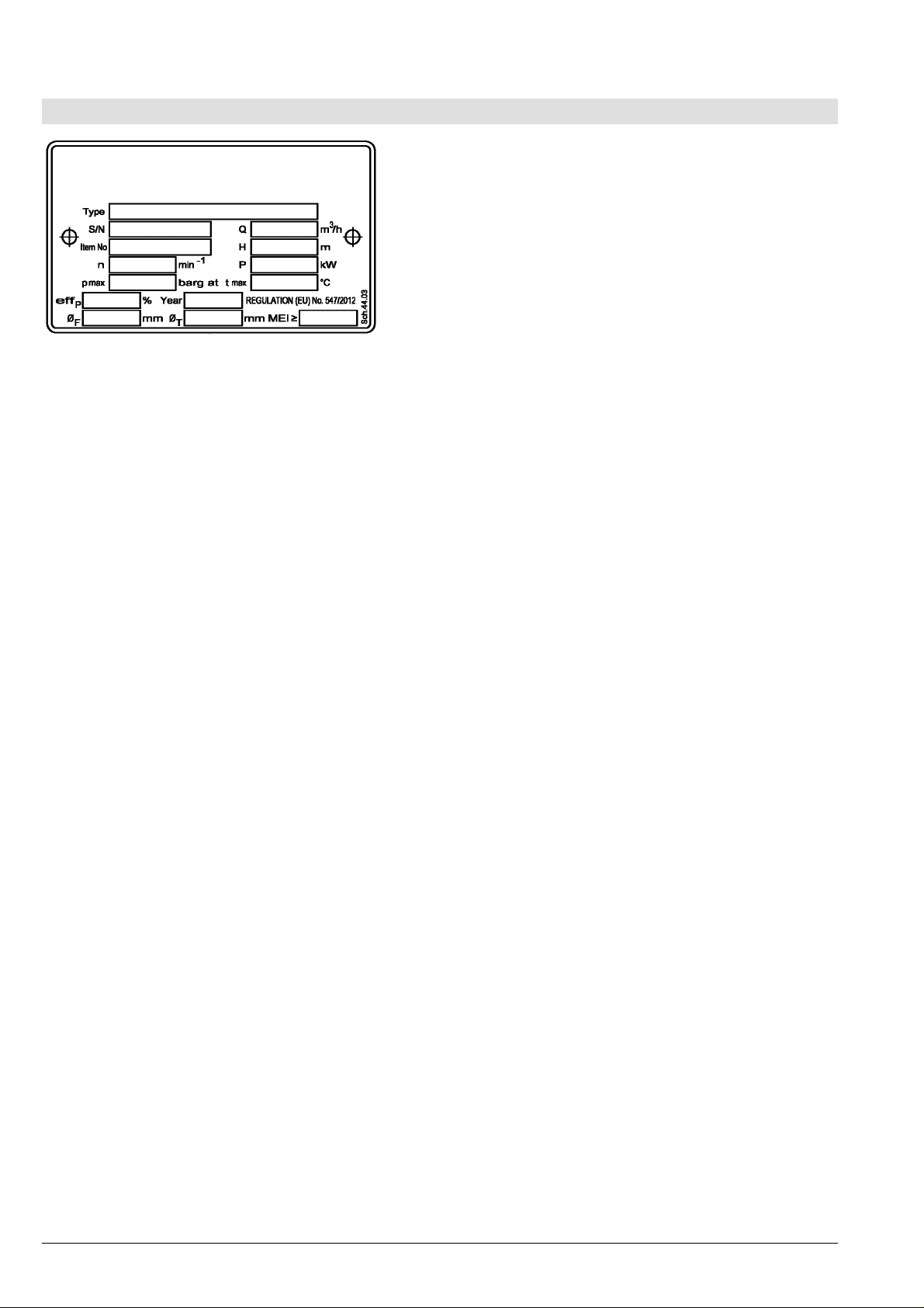
Leistungsschild
Type *) Typenbezeichnung der Pumpe
S/N *) Fabrikationsnummer
Item No kundenspezifische Auftragsnummer
n Drehzahl
Maximal zulässiger Gehäuse-Betriebsdruck
p
max
(=der höchste Austrittsdruck bei der festgelegten Arbeitstemperatur, bis zu dem das
Pumpengehäuse verwendet werden kann).
Q Förderstrom im Betriebspunkt
H Förderhöhe (Energiehöhe) im Betriebspunkt
P Antriebsleistung im Betriebspunkt
Maximal zulässige Arbeitstemperatur der
t
max
Förderflüssigkeit
Wirkungsgrad
eff
p
Year Baujahr
Laufraddurchmesser, voll
Ø
F
Laufraddurchmesser, abgedreht
Ø
T
MEI Mindesteffizienzindex der Pumpe
*) Mit diesen Angaben sind für den Hersteller alle
Ausführungsdetails und Werkstoffe genau definiert.
Sie sind daher bei allen Rückfragen beim Hersteller
und bei der Bestellung von Ersatzteilen unbedingt
anzugeben.
Seite 2
Page 7

Einbau-, Betriebs- und Wartungsanleitung Baureihe L, LN
r
1. Allgemeines
Dieses Produkt entspricht den Anforderungen der
Maschinenrichtlinie 2006/42/EG.
Das Personal für Montage, Bedienung,
Inspektion und Wartung muss die
entsprechenden Kenntnisse der Unfallverhütungsvorschriften bzw. Qualifikation fü
diese Arbeiten aufweisen. Liegen beim
Personal nicht die entsprechenden Kenntnisse
vor, so ist dieses zu unterweisen.
Die Betriebssicherheit der gelief erten Pum pe bzw. des
gelieferten Aggregates (= Pumpe mit Motor) ist nur
beim bestimmungsgemäßen Gebrauch entsprechend
dem beiliegenden Datenblatt und / oder der
Auftragsbestätigung bzw. Kapitel 6 "Inbetriebnahme,
Betrieb, Außerbetriebnahme" gewährleistet.
Der Betreiber ist für die Einhaltung der Instruktionen
und Sicherheitsvorkehrungen gemäß dieser
Betriebsanleitung verantwortlich.
Ein störungsfreier Betrieb der Pumpe bzw. des
Aggregates wird nur dann erreicht, wenn die Montage
und Wartung nach den im Maschinenbau und in der
Elektrotechnik gültigen Regeln sorgf ältig durchgeführt
wird.
Sofern nicht alle Informationen in dieser
Betriebsanleitung gefunden werden, ist rückzufragen.
Der Hersteller übernimmt für die Pumpe bzw. das
Aggregat keine Verantwortung, wenn diese
Betriebsanleitung nicht beachtet wird.
Diese Betriebsanleitung ist für künftige Verwendung
sorgfältig aufzubewahren.
Bei Weitergabe dies er Pumpe oder dieses Aggregates
an Dritte ist diese Betriebsanleitung sowie die in der
Auftragsbestätigung genannten Betriebsbedingungen
und Einsatzgrenzen unbedingt vollständig mitzugeben.
Diese Betriebsanleitung berücksichtigt weder alle
Konstruktionseinzelheiten und Varianten noch alle
möglichen Zufälligkeiten und Ereignisse, die bei
Montage, Betrieb und Wartung auftreten können.
Das Urheberrecht an dieser Betriebsanleitung
verbleibt uns, sie ist nur dem Bes itzer der Pum pe bzw.
des Aggregates zum persönlichen Gebrauch
anvertraut. Die Bedienungsanleitung enthält
Vorschriften technischer Art und Zeichnungen, die
weder vollständig noch teilweise vervielfältigt,
verbreitet oder zu Zwecken des Wettbewerbs
unbefugt verwendet oder an andere mitgeteilt werden
dürfen.
1.1 Gewährleistung
Gewährleistung gemäß unseren Lieferbedingungen
bzw. der Auftragsbestätigung.
Instandsetzungsarbeiten während der Garantiezeit
dürfen nur durch uns durchgeführt werden oder setzen
unsere schriftliche Zustimmung voraus. Andernfalls
geht der Garantieanspruch verloren.
Längerfristige Garantien beziehen sich grundsätzlich
nur auf die einwandfreie Verarbeitung und
Verwendung des spezifizierten Materials.
Ausgenommen von der Garantie ist natürliche
Abnutzung und Verschleiß, sowie sämtliche
Verschleißteile wie beispielsweise Laufräder,
Wellenabdichtungen, Wellen, Wellenschutzhülsen,
Lager, Spalt- und Schleißringe, usw., weiters durch
Transport oder unsachgem äße Lagerung verursachte
Schäden.
Voraussetzung für die Gewährleistung ist, dass die
Pumpe bzw. das Aggregat gemäß der am
Typenschild, im Datenblatt und / oder der
Auftragsbestätigung angeführten Betriebsbedingungen eingesetzt wird. Das gilt insbesondere für die
Beständigkeit der Materialien sowie einwandfreie
Funktion der Pumpe und Wellenabdichtung.
Sollten die tatsächlichen Betriebsbedingungen in
einem oder mehreren Punkten abweichen, so muss
die Eignung durch Rückfrage bei uns schriftlich
bestätigt werden.
2. Sicherheitshinweise
Diese Betriebsanleitung enthält grundlegende
Hinweise, die bei der Aufstellung, Inbetriebnahme
sowie während des Betriebes und bei der W artung zu
beachten sind.
Daher ist diese Betriebsanleitung unbedingt vor
Montage und Inbetriebnahme vom zuständigen
Fachpersonal bzw. dem Betreiber der Anlage zu
lesen und muss s tändig griffbereit am Einsatzort der
Pumpe bzw. des Aggregates zur Verfügung stehen.
Diese Betriebsanleitung berücksichtigt nicht die
allgemeinen Unfallverhütungsvorschriften sowie
ortsbezogene Sicherheits- und / oder
Betriebsvorschriften. Für deren Einhaltung (auch
durch hinzugezogenes Montagepersonal) ist der
Betreiber verantwortlich.
Ebenso sind Vorschriften und Sicherheitsvorkehrungen bezüglich der Handhabung und
Entsorgung des geförderten Mediums und / oder
Seite 3
Hilfsmedien für Spülung, Sperrung, Schmierung, usw.,
insbesondere wenn diese explosiv, giftig, heiß, usw.
sind, nicht Teil dieser Betriebsanleitung.
Für die fachgerechte und vorschriftkonforme
Handhabung ist ausschließlich der Betreiber
verantwortlich.
2.1 Kennzeichnung von Hinweisen in der
Betriebsanleitung
Die in dieser Betriebsanleitung enthaltenen
Sicherheitshinweise sind mit Sicherheitszeichen nach
DIN 4844 besonders gekennzeichnet:
Sicherheitshinweis!
Bei Nichtbeachtung kann die Pumpe und deren
Funktion beeinträchtigt werden.
Page 8

Einbau-, Betriebs- und Wartungsanleitung Baureihe L, LN
Allgemeines Gefahrensymbol!
Personen können gefährdet werden.
Warnung vor elektrischer Spannung!
Direkt auf der Pumpe bzw. dem Aggregat angebrachte
Sicherheitshinweise müssen unbedingt beachtet und
in vollständig lesbarem Zustand gehalten werden.
In gleicher Weise, wie diese PumpenBetriebsanleitung sind auch alle eventuell
beiliegenden Betriebsanleitungen von Zubehör
(z.B. für Motor) zu beachten und verfügbar zu
halten.
2.2 Gefahren bei Nichtbeachtung der
Sicherheitshinweise
Die Nichtbeachtung der Sicherheitshinweise kann
zum Verlust jeglicher Schadensersatzansprüche
führen.
Nichtbeachtung kann folgende G efährdung nach sich
ziehen :
Versagen wichtiger Funktionen der Maschine oder
Anlage.
Versagen von elektronischen Geräten und
Messinstrumenten durch Magnetfelder.
Gefährdung von Personen und deren
persönlichem Eigentum durch Magnetfelder.
Gefährdung von Personen durch elektrische,
mechanische und chemische Einwirkungen.
Gefährdungen der Umwelt durch Leckage von
gefährlichen Stoffen.
2.3 Sicherheitshinweise für den Betreiber
/ Bediener
In Abhängigkeit der Betriebsbedingungen sind
durch Verschleiß, Korros ion oder alterungsbedingt
die Lebensdauer und damit die spezifizierten
Eigenschaften begrenzt. Der Betreiber hat dafür
Sorge zu tragen, dass durch regelmäßige
Kontrolle und War tung alle Teile rechtzeitig ersetzt
werden, die einen sicheren Betrieb nicht mehr
gewährleisten. Jede Beobachtung einer
abnormalen Betriebsweise oder einer
wahrnehmbaren Beschädigung verbietet die
weitere Benutzung.
Anlagen, bei denen der Ausfall oder das Vers agen
zu Personen- oder Sachschäden führen kann,
sind mit Alarmeinrichtungen und / oder
Reserveaggregaten auszustatten und deren
Funktionstüchtigkeit in regelmäßigen Abständen
zu prüfen.
Besteht Verletzungsgefahr durch heiße oder kalte
Maschinenteile, müssen diese Teile bauseitig
gegen Berührung gesichert sein, bzw.
entsprechende Warnhinweise angebracht werden.
Berührungsschutz für sich bewegende Teile (z.B.
Kupplungsschutz) darf bei sich in Betrieb
befindlichen Anlagen nicht entfernt werden.
Bei Pumpen bzw. Aggregaten mit einem
Schallpegel über 85 dB(A) ist bei längerem
Aufenthalt in der unmittelbaren Umgebung ein
Gehörschutz zu verwenden.
Leckagen (z.B. der Wellenabdichtung)
gefährlicher Fördergüter (z.B. explosiv, giftig,
heiß) müssen so abgeführt werden, dass keine
Gefährdung für Personen und die Umwelt
entsteht. Gesetzliche Bestimmungen sind
einzuhalten.
Gefährdungen durch elektrische Energie sind
auszuschließen (z.B. durch Beachten der örtlich
geltenden Vorschriften für elektrische Anlagen).
Bei Arbeiten an spannungsführenden Bauteilen
vorher Netzstecker ziehen bzw. Hauptschalter
ausschalten und Sicherung herausdrehen. Ein
Motorschutzschalter ist vorzusehen.
2.4 Sicherheitshinweise für Wartungs-,
Inspektions- und Montagearbeiten
Der Betreiber hat dafür zu sorgen, dass alle
Wartungs -, Inspektions - und Montagearbeiten von
autorisiertem und qualifiziertem Fachpersonal
ausgeführt werden, das sich durch eingehendes
Studium der Betriebsanleitung ausreichend
informiert hat.
Grundsätzlich sind Arbeiten an der Pumpe oder
am Aggregat nur im Stills tand und im drucklosen
Zustand durchzuführen. Alle Teile müssen
Umgebungstemperatur angenommen haben.
Sicherstellen, dass während der Arbeiten der
Motor von niemand in Betrieb gesetzt werden
kann. Die in der Betriebsanleitung beschriebene
Vorgehensweise zum Stillsetzen der Anlage mus s
unbedingt eingehalten werden. Pumpen oder
Anlagen, die gesundheitsgefährdende Medien
fördern, müs sen vor dem Zerlegen dek ontam inier t
werden. Sicherheitsdatenblätter der jeweiligen
Fördermedien beachten. Unmittelbar nach
Abschluss der Arbeiten müssen alle Sicherheitsund Schutzeinrichtungen wieder angebracht bzw.
in Funktion gebracht werden.
2.5 Eigenmächtiger Umbau und Ersatzteilherstellung
Umbau oder Veränderungen der Maschine sind nur
nach Absprache mit dem Hersteller zulässig.
Originalersatzteile und vom Hersteller autorisiertes
Zubehör dienen der Sicherheit.
Die Verwendung anderer Teile kann die Haftung für
die daraus entstehenden Folgen aufheben.
2.6 Unzulässige Betriebsweisen
Die Betriebssicherheit der gelieferten Mas chine ist nur
bei bestimm ungsgemäßer Verwendung entsprechend
der nachfolgenden Kapitel der Betriebsanleitung
gewährleistet.
Die im Datenblatt und / oder der Auf tragsbestätigung
angegebenen Grenzwerte dürfen auf keinen Fall
überschritten werden.
Seite 4
Page 9
Einbau-, Betriebs- und Wartungsanleitung Baureihe L, LN
r
r
A
A
2.7 Bestimmungsgemäße Verwendung
2.7.1 Drehzahl, Druck, Temperatur
Anlagenseitig müssen geeignete Sicherheitsmaßnahmen vorgesehen sein, damit Drehzahl,
Druck und Temperatur in der Pumpe und an de
Wellenabdichtung die im Datenblatt und / ode
der Auftragsbestätigung angegebenen
Grenzwerte mit Sicherheit nicht übersteigen.
ngegebene Zulaufdrücke (Systemdrücke)
dürfen auch nicht unterschritten werden.
Weiters sind Druckstöße, wie sie bei zu raschem
Abschalten der Anlage entstehen können, unbedingt
von der Pumpe fernzuhalten (z.B. durch drucks eitiges
Rückschlagventil, Schwungscheibe, Windkessel).
Rasche Temperaturwechsel sind zu vermeiden. Sie
können einen Tem peratursc hock ver ursachen und zur
Zerstörung oder Beeinträchtigung der Funktion
einzelner Komponenten führen.
2.7.2 Zulässige Stutzenkräfte und Momente
Grundsätzlich muss die Saug- und Druck leitung
so ausgeführt sein, dass möglichst geringe
Kräfte auf die Pumpe wirken. Ist dies nicht
2.7.3 NPSH
Das Fördermedium muss am Laufradeintritt
einen Mindestdruck NPSH aufweisen, damit
kavitationsfreies Arbeiten ges ichert ist bzw. ein
bschnappen der Pum pe verhindert wird. Diese
Bedingung ist erfüllt, wenn der Anlagen-NPSHWert (NPSHA) unter allen Betriebsbedingungen
mit Sicherheit über dem Pumpen-NPSH-Wert
(NPSHR) liegt.
Besonders bei Förderung von Flüssigkeit nahe dem
Siedepunkt ist auf den NPSH-W ert zu achten. Wenn
der Pumpen-NPSH-Wert unterschritten wird, kann
dies zu Materialschäden infolge Kavitation bis zu
Zerstörungen durch Überhitzen führen.
Der Pumpen-NPSH-Wert (NPSHR) ist bei jeder
Pumpentype in den Kennlinienblättern angegeben.
2.7.4 Rücklauf
In Anlagen, wo Pumpen in einem geschlossenen
System unter Druck (Gaspolster, Dampfdruck)
arbeiten, darf eine Entspannung des Gaspolst ers auf
keinen Fall über die Pumpe erfolgen, da die
Rücklaufdrehzahl ein Vielfaches der Betriebsdrehzahl
sein kann und das Aggregat zerstört würde.
durchführbar, so dürfen die im Kapitel 3.5
angegebenen Werte auf keinen Fall
überschritten werden. Dies gilt sowohl im
Betrieb als auch bei Stills tand der Pumpe, also
für alle in der Anlage vorkommenden Drücke
und Temperaturen.
3. Ausführungsbeschreibung
3.1 Bauart
Die Pumpen der Baureihe L und LN sind einstufige
Spiralgehäusepumpen nach DIN EN 733.
Die Pumpen eignen sich nicht für gefährliche
oder entflammbare Flüssigkeiten. Nicht
geeignet für den Einsatz im Ex-Bereich!
Maximaler Betriebsdruck: siehe Kapitel 3.2 "Maximal
zulässige Betriebsdrücke und Temperatur".
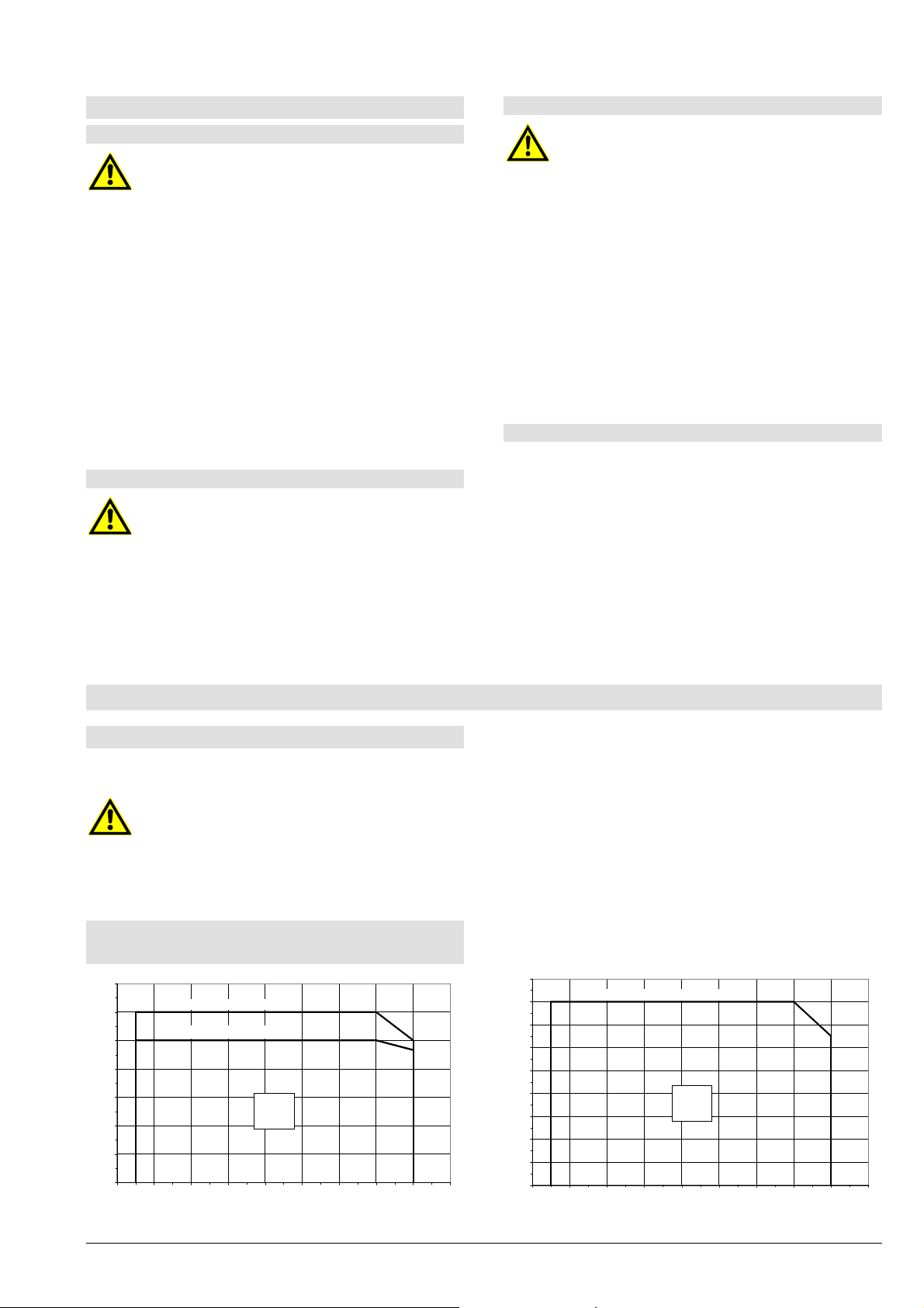
3.2 Maximal zulässige Betriebsdrücke
und Temperatur
14
12
[bar]
10
all w C
8
6
4
2
Druck - Pression - Pressure p
0
Seite 5
Flansche/Bridges/Flanges PN 16, 0.6025
Flansche/Bridges/Flanges PN 10, 0.6025
L
-20 0 20 40 60 80 1 00 120 140 160
Temperatur - Température - Temperature t
max op
[°C]
Die zulässigen Einsatzbedingungen und die
Ausführungsdetails der gelieferten Pumpe sind im
beiliegenden Datenblatt und / oder der
Auftragsbestätigung angegeben.
Die zur gelieferten Pumpe passende PrinzipSchnittzeichnung sowie das Gewicht der Pumpe und
des kompletten Aggregates finden Sie im Anhang.
18
16
14
[bar]
all w C
12
10
8
6
4
Druck - Pression - Pressure p
2
0
-20 0 20 40 60 80 100 120 140 160
Flansche/Bridges/Flanges PN 10/16, 0.6020
LN
Temperatur - Température - Temperature t
max op
[°C]
Page 10
Einbau-, Betriebs- und Wartungsanleitung Baureihe L, LN
3.3 Wellenabdichtung
3.3.1 Aufbau der Gleitringdichtung
Diese Wellenabdichtung ist eine EinzelGleitringdichtung mit Einbaumaßen nach EN 12756
(DIN 24960) Ausführ ung "K". API Plan 02 / ISO Plan
00. Es ist keine zusätzliche Spülung des
Gleitringdichtungsraumes erforderlich. Der Gleitring-
dichtungsraum m uss bei Betrieb der Pumpe stets m it
Flüssigkeit gefüllt sein.
Angaben über Werkstoffe und Einsatzbereich der
verwendeten Gleitringdichtungen entnehmen Sie dem
Datenblatt in der Betriebsanleitung bzw. der
Auftragsbestätigung.
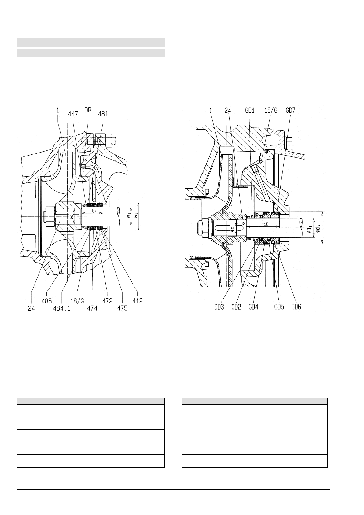
Innerer Aufbau der Gleitringdichtung siehe folgende
Darstellungen.
L LN
Teilbezeichnungen:
1 Laufrad
18/G Zwischenwand
24 Welle
412 Winkelmanschette
447 Feder
472 Gleitring
474 Scheibe
475 Gegenring
481 Balg
484.1 Winkelring
Teilbezeichnungen:
1 Laufrad
18/G Zwischenwand
24 Welle
GD1 Feder mit Mitnehmerwirkung
GD2 O-Ring (Welle)
GD3 Gleitringhalterung
GD4 O-Ring (Gleitring)
GD5 Gleitring
GD6 Gegenring
GD7 O-Ring (Gegenring)
485 Mitnehmer
DR Drossel
Pumpengröße Lagerträger d1 d7 dL l1k Pumpengröße Lagerträger d1 d7 dL l1k
L 65-315, L 80-315
L 100-160, L 100-200
L 100-250, L 100-315
L 125-250
L 125-200, L 125-270
L 125-315, L 150-250
L 150-315
32L 40 58 32 45
42L 50 70 42 47,5
LN 32-125, LN 32-160
LN 32-200, LN 40-125
LN 40-160, LN 40-200
LN 40-250, LN 50-125
LN 50-160, LN 50-200
LN 50-250, LN 65-125
LN 65-160, LN 65-200
24LN 22 37 18 37,5
LN 80-160
L 80-400, L 100-400
L 125-400, L 150-400
*) ... Bei diesen Pum pengrößen i st l1k+Distanzhülse 70,5mm.
Die eingetragenen Maße entsprechen Gleitringdic htungen nach EN 12756 mit Baulänge l
Maße in mm unverbindlich - Techni sche Änderungen vorbehalten!
42L 50 70 42 118*)
LN 65-250, LN 80-200
LN 80-250
.
1k
32LN 28 43 24 42,5
Seite 6
Page 11
Einbau-, Betriebs- und Wartungsanleitung Baureihe L, LN
A
r
p
3.3.2 Allgemeine Hinweise
Die Wiederverwendung von Gleitringdichtungen, die bereits längere Zeit im Einsatz
waren, birgt die Gefahr von Undichtheiten an
der Gleitfläche nach dem Wiedereinbau. Es
wird daher der Ersatz der Gleitringdichtung
durch eine neue empfohlen. Die ausgebaute
Gleitringdichtung kann vom Hersteller überholt
werden und als Ersatz-Gleitringdichtung dienen.
3.3.3 Hinweise für die Montage
uf größte Sauberkeit achten! Besonders die
Gleitflächen müssen sauber, trocken und
unbeschädigt bleiben. Auch keine Schmieroder Gleitmittel auf die Gleitflächen de
Gleitringdichtung auftragen.
Falls bei der Ersatzgleitringdichtung Gleitmittel
beigepackt ist, dann dieses verwenden.
Mineralische Fette oder Öle nur dann
verwenden, wenn völlig sicher ist, dass die
Elastomere der Gleitringdichtung ölbeständig
sind. Kein Silicon verwenden.
Nur Gleitmittel verwenden, von denen
sichergestellt ist, dass es zwischen ihnen und
dem Fördermedium zu keiner gefährlichen
Reaktion kommen kann.
Stellen Sie alle erforderlichen T eile bereit, dam it
die Montage zügig vor sich geht. Die Gleitmittel
wirken nur kurze Zeit, so dass danach die
Verschiebbarkeit und damit die automatische
Einstellung der Elastomere verloren geht.
Schieben Sie die Elastomere nie über scharfe
Kanten. Falls erforderlich Montagehülsen
verwenden.
Gleitringdichtungen mit Faltenbälgen bei
Montage so schieben, dass der Balg
zusammengedrückt und nicht gestreckt wird
(Reißgefahr!).
3.4 Lagerung
Die Lagerung der Pumpe erfolgt in auf
Lagerlebensdauer fettgeschmierten Wälzlagern.
3.4.1 Verwendete Lager
Die genaue Bezeichnung Ihrer Pumpe finden Sie auf
der Auftragsbestätigung und / oder dem
Leistungsschild.
Pumpengröße L
L 65-315, L 80-315
L 100-160, L 100-200
L 100-250, L 100-315
L 125-250
L 80-400, L 100-400
L 125-200, L 125-270
L 125-315, L 125-400
L 150-250, L 150-315
L 150-400
Lager-
träger
32L 6308 2Z/C3 6308 2Z/C3
42L 6310 2Z/C3 6310 2Z/C3
antriebseitig pumpenseitig
Lagertype
Pumpengröße LN
LN 32-125/121 U.VN 24LN 6305 2Z/C3-WT 6305 2Z/C3-WT
LN 32-125/136 U.VN 24LN 6305 2Z/C3-WT 6305 2Z/C3-WT
LN 32-160/150 U.VN 24LN 6305 2Z/C3-WT 6305 2Z/C3-WT
LN 32-160/168 U.VN 24LN 6305 2Z/C3-WT 6305 2Z/C3-WT
LN 32-200/188 U.VN 24LN 6305 2Z/C3-WT 6305 2Z/C3-WT
LN 32-200/205 U.VN 24LN 6305 2Z/C3-WT 6305 2Z/C3-WT
LN 40-125/112 U.VN 24LN 6305 2Z/C3-WT 6305 2Z/C3-WT
LN 40-125/126 U.VN 24LN 6305 2Z/C3-WT 6305 2Z/C3-WT
LN 40-125/143 U.VN 24LN 6305 2Z/C3-WT 6305 2Z/C3-WT
LN 40-160/159 U.VN 24LN 6305 2Z/C3-WT 6305 2Z/C3-WT
LN 40-160/171 U.VN 24LN 6305 2Z/C3-WT 6305 2Z/C3-WT
LN 40-200/190 U.VN 24LN 6305 2Z/C3-WT 6305 2Z/C3-WT
LN 40-200/209 U.VN 24LN 6305 2Z/C3-WT 6305 2Z/C3-WT
LN 40-250/218 U.VN 24LN 6305 2Z/C3-WT 6305 2Z/C3-WT
LN 40-250/233 U.VN 24LN 6305 2Z/C3-WT 6305 2Z/C3-WT
LN 40-250/251 U.VN 24LN 6305 2Z/C3-WT 6306 2Z/C3-WT
LN 50-125/119 U.VN 24LN 6305 2Z/C3-WT 6305 2Z/C3-WT
LN 50-125/130 U.VN 24LN 6305 2Z/C3-WT 6305 2Z/C3-WT
LN 50-125/139 U.VN 24LN 6305 2Z/C3-WT 6305 2Z/C3-WT
LN 50-160/158 U.VN 24LN 6305 2Z/C3-WT 6305 2Z/C3-WT
LN 50-160/174 U.VN 24LN 6305 2Z/C3-WT 6305 2Z/C3-WT
LN 50-200/197 U.VN 24LN 6305 2Z/C3-WT 6305 2Z/C3-WT
LN 50-200/209 U.VN 24LN 6305 2Z/C3-WT 6305 2Z/C3-WT
LN 50-250/224 U.VN 24LN 6305 2Z/C3-WT 6306 2Z/C3-WT
LN 50-250/237 U.VN 24LN 6305 2Z/C3-WT 6306 2Z/C3-WT
LN 50-250/250 U.VN 24LN 6305 2Z/C3-WT 6306 2Z/C3-WT
LN 65-125/121 U.VN 24LN 6305 2Z/C3-WT 6305 2Z/C3-WT
LN 65-125/129 U.VN 24LN 6305 2Z/C3-WT 6305 2Z/C3-WT
LN 65-125/140 U.VN 24LN 6305 2Z/C3-WT 6305 2Z/C3-WT
LN 65-160/161 U..N 24LN 6305 2Z/C3-WT 6305 2Z/C3-WT
LN 65-160/168 U..N 24LN 6305 2Z/C3-WT 6306 2Z/C3-WT
LN 65-160/178 U..N 24LN 6305 2Z/C3-WT 6306 2Z/C3-WT
LN 65-200/180 U..N 24LN 6305 2Z/C3-WT 6306 2Z/C3-WT
LN 65-200/187 U..N 24LN 6305 2Z/C3-WT 6306 2Z/C3-WT
LN 65-200/198 U..N 24LN 6305 2Z/C3-WT 6306 2Z/C3-WT
LN 65-200/210 U..N 24LN 6305 2Z/C3-WT 6306 2Z/C3-WT
LN 65-250/220 U..N 32LN 6308 2Z/C3-WT 6308 2Z/C3-WT
LN 65-250/241 U..N 32LN 6308 2Z/C3-WT 6308 2Z/C3-WT
LN 65-250/258 U..N 32LN 6308 2Z/C3-WT 6308 2Z/C3-WT
LN 80-160/152 U..N 24LN 6305 2Z/C3-WT 6306 2Z/C3-WT
LN 80-160/163 U..N 24LN 6305 2Z/C3-WT 6306 2Z/C3-WT
LN 80-160/173 U..N 24LN 6305 2Z/C3-WT 6306 2Z/C3-WT
LN 80-200/189 U..N 32LN 6308 2Z/C3-WT 6308 2Z/C3-WT
LN 80-200/209 U..N 32LN 6308 2Z/C3-WT 6308 2Z/C3-WT
LN 80-250/225 U..N 32LN 6308 2Z/C3-WT 6308 2Z/C3-WT
LN 80-250/238 U..N 32LN 6308 2Z/C3-WT 6308 2Z/C3-WT
LN 80-250/256 U..N 32LN 6308 2Z/C3-WT 6308 2Z/C3-WT
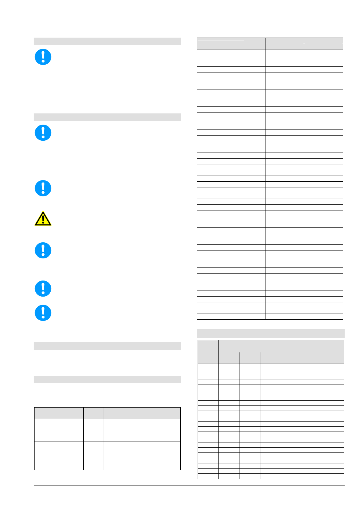
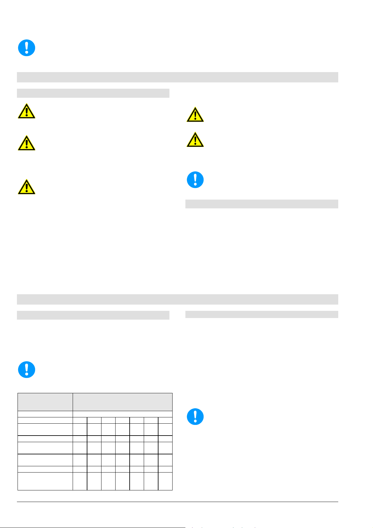
3.5 Richtwerte für Schalldruckpegel
Nennleist
ungsbed
arf PN in
kW
0,55 50,5 49,5 49,0 58,0 52,0 51,5
0,75 52,0 51,0 50,5 59,0 54,0 53,0
1,1 54,0 53,0 52,5 60,0 55,5 54,5
1,5 55,5 55,0 54,5 63,5 57,0 56,0
2,2 58,0 57,0 56,5 64,5 59,0 58,5
3,0 59,5 58,5 58,0 68,5 61,0 62,0
4,0 61,0 60,0 59,5 69,0 63,0 63,0
5,5 63,0 62,0 61,5 70,0 65,0 65,0
7,5 64,5 63,5 63,0 70,5 67,0 67,0
11,0 66,5 65,5 65,0 72,0 69,0 68,5
15,0 68,0 67,0 66,5 72,5 70,0 70,5
18,5 69,0 68,5 68,0 73,0 70,5 74,0
22,0 70,5 69,5 69,0 74,5 71,0 74,0
30,0 72,0 71,0 70,5 75,0 72,0 73,0
37,0 73,0 72,0 71,5 76,0 73,5 73,5
45,0 74,0 73,0 72,5 77,0 74,5 73,5
55,0 75,5 74,5 74,0 78,0 75,5 75,0
75,0 77,0 76,0 75,5 80,0 76,5 76,0
90,0 78,0 77,0 -- 80,5 77,5 --
110,0 79,0 78,0 -- 82,5 78,5 -132,0 80,0 79,0 -- 83,0 79,5 -160,0 81,0 80,0 -- 83,5 80,5 --
2950
min-1
Seite 7
Lager-
träger
Schalldruckpegel L
Pumpe alleine Pumpe + Motor
1450
min-1
antriebseitig pumpenseitig
975
min-1
Lagertype
in dB(A)
A
2950
min-1
1450
min-1
975
min-1
Page 12
Einbau-, Betriebs- und Wartungsanleitung Baureihe L, LN
Schalldruckpegel LpA gemessen in 1 m Abstand vom
Pumpenumriss nach DIN 45635, Teil 1 und 24. Raum- und
Fundamenteinflüsse sind nicht berücksichtigt. Die Toleranz für
diese Werte beträgt 3 dB(A).
Zuschlag bei 60 Hz-Betrieb:
Pumpe allein:
Pumpe mit Motor: +4 dB(A)
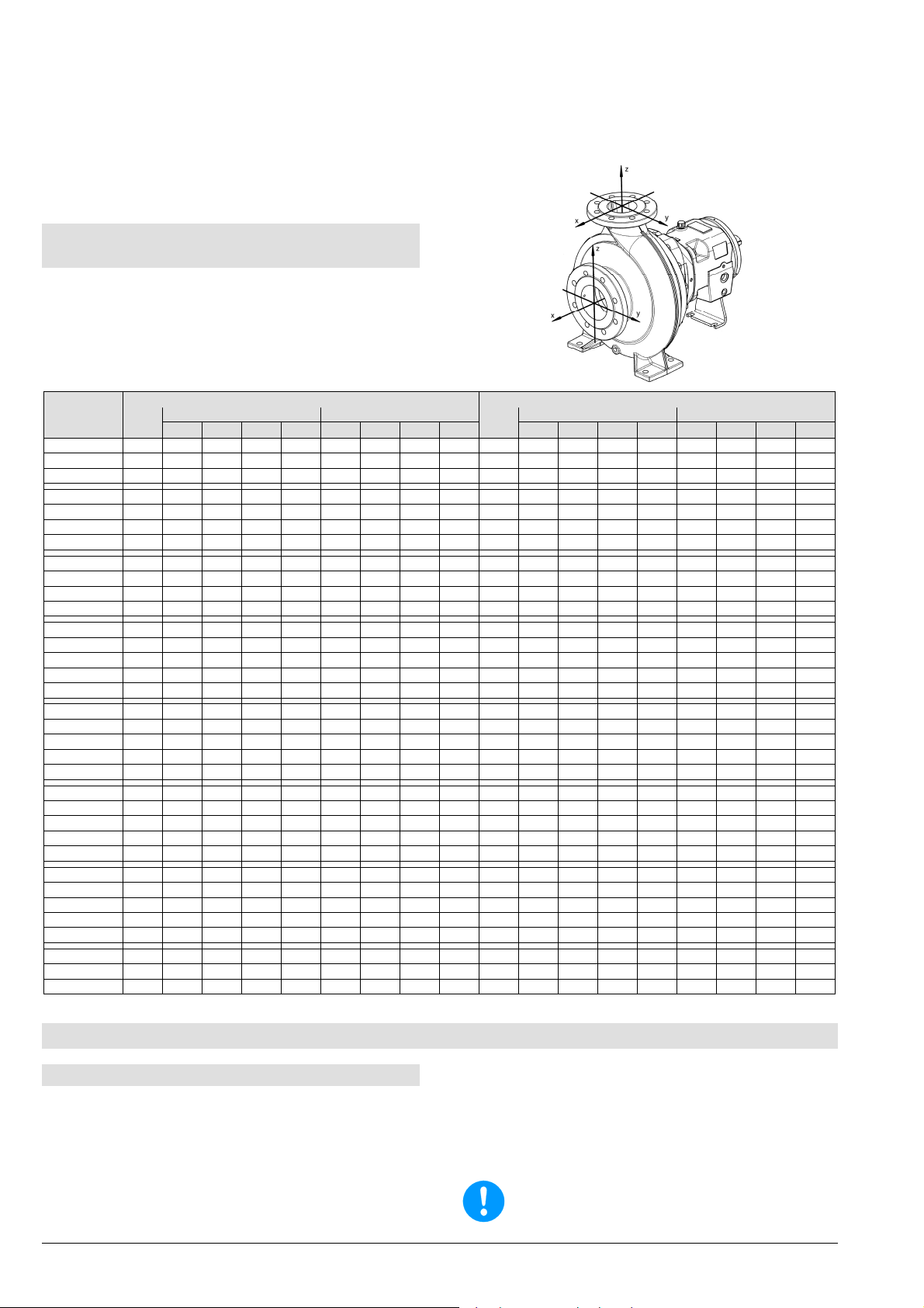
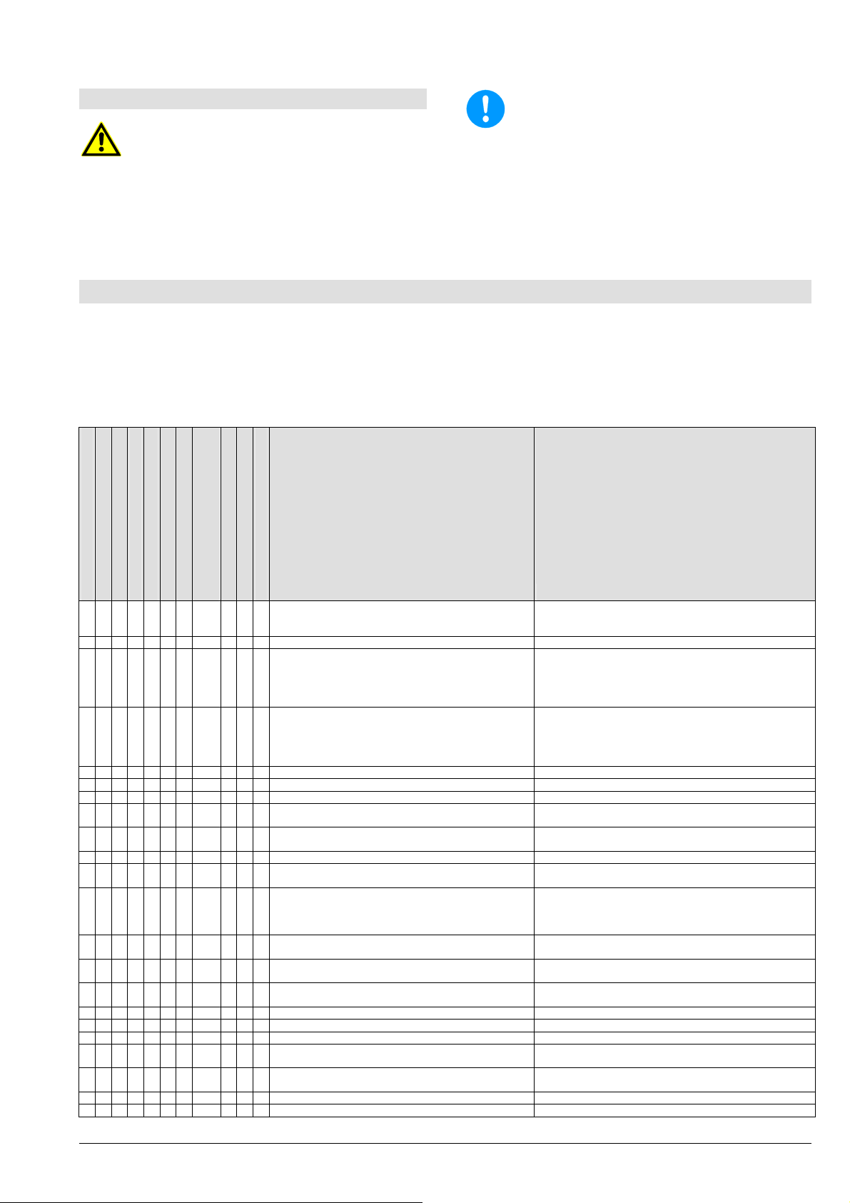
3.6 Zulässige Stutzenkräfte und Momente
an den Pumpenstutzen ...
... in Anlehnung an die Europump-Empfehlung für
Pumpen nach ISO 5199.
Die Angaben für Kräfte und Momente gelten nur für
statische Rohrleitungslasten. Die in der Tabelle
angegebenen Werte gelten f ür Pumpenaggregate mit
Standard-Fundamentplatten (ausgegossen).
Baugrößen
DN
Kräfte in N Momente in Nm
Fx Fy Fz
LN 32-125 50 578 525 473 910 490 350 403 718 32 315 298 368 578 385 263 298 560
LN 32-160 50 578 525 473 910 490 350 403 718 32 315 298 368 578 385 263 298 560
LN 32-200 50 578 525 473 910 490 350 403 718 32 315 298 368 578 385 263 298 560
LN 40-125 65 735 648 595 1155 525 385 420 770 40 385 350 438 683 455 315 368 665
LN 40-160 65 735 648 595 1155 525 385 420 770 40 385 350 438 683 455 315 368 665
LN 40-200 65 735 648 595 1155 525 385 420 770 40 385 350 438 683 455 315 368 665
LN 40-250 65 735 648 595 1155 525 385 420 770 40 385 350 438 683 455 315 368 665
LN 50-125 65 735 648 595 1155 525 385 420 770 50 525 473 578 910 490 350 403 718
LN 50-160 65 735 648 595 1155 525 385 420 770 50 525 473 578 910 490 350 403 718
LN 50-200 65 735 648 595 1155 525 385 420 770 50 525 473 578 910 490 350 403 718
LN 50-250 65 735 648 595 1155 525 385 420 770 50 525 473 578 910 490 350 403 718
LN 65-125 80 875 788 718 1383 560 403 455 823 65 648 595 735 1155 525 385 420 770
LN 65-160 80 875 788 718 1383 560 403 455 823 65 648 595 735 1155 525 385 420 770
LN 65-200 80 875 788 718 1383 560 403 455 823 65 648 595 735 1155 525 385 420 770
LN 65-250 80 875 788 718 1383 560 403 455 823 65 648 595 735 1155 525 385 420 770
L 65-315 80 875 788 718 1383 560 403 455 823 65 648 595 735 1155 525 385 420 770
LN 80-160 100 1173 1050 945 1838 613 438 508 910 80 788 718 875 1383 560 403 455 823
LN 80-200 100 1173 1050 945 1838 613 438 508 910 80 788 718 875 1383 560 403 455 823
LN 80-250 100 1173 1050 945 1838 613 438 508 910 80 788 718 875 1383 560 403 455 823
L 80-315 100 1173 1050 945 1838 613 438 508 910 80 788 718 875 1383 560 403 455 823
L 80-400 100 1173 1050 945 1838 613 438 508 910 80 788 718 875 1383 560 403 455 823
L 100-160 125 1383 1243 1120 2170 735 525 665 1068 100 1050 945 1173 1838 613 438 508 910
L 100-200 125 1383 1243 1120 2170 735 525 665 1068 100 1050 945 1173 1838 613 438 508 910
L 100-250 125 1383 1243 1120 2170 735 525 665 1068 100 1050 945 1173 1838 613 438 508 910
L 100-315 125 1383 1243 1120 2170 735 525 665 1068 100 1050 945 1173 1838 613 438 508 910
L 100-400 125 1383 1243 1120 2170 735 525 665 1068 100 1050 945 1173 1838 613 438 508 910
L 125-200 150 1750 1575 1418 2748 875 613 718 1278 125 1243 1120 1383 2170 735 525 665 1068
L 125-250 150 1750 1575 1418 2748 875 613 718 1278 125 1243 1120 1383 2170 735 525 665 1068
L 125-270 150 1750 1575 1418 2748 875 613 718 1278 125 1243 1120 1383 2170 735 525 665 1068
L 125-315 150 1750 1575 1418 2748 875 613 718 1278 125 1243 1120 1383 2170 735 525 665 1068
L 125-400 150 1750 1575 1418 2748 875 613 718 1278 125 1243 1120 1383 2170 735 525 665 1068
L 150-250 200 2345 2100 1890 3658 1138 805 928 1680 150 1575 1418 1750 2748 875 613 718 1278
L 150-315 200 2345 2100 1890 3658 1138 805 928 1680 150 1575 1418 1750 2748 875 613 718 1278
L 150-400 200 2345 2100 1890 3658 1138 805 928 1680 150 1575 1418 1750 2748 875 613 718 1278
Saugstutzen Druckstutzen
Mx My Mz
F
Alle Werte für Kräfte und Momente sind auf den
Standardwerkstoff EN-GJL-200 (Baureihe LN) bzw.
EN-GJL-250 (Baureihe L) bezogen.
Kräfte in N Momente in Nm
Fx Fy Fz
Mx My Mz
F
M
M
DN
4. Transport, Handhabung, Zwischenlagerung
4.1 Transport, Handhabung
Überprüfen Sie die Pum pe / das Aggregat gleich
bei Anlieferung bzw. Eingang der Sendung auf
Vollständigkeit oder Schäden.
Der T ransport der Pumpe / des Aggregates muss
fachgerecht und schonend durchgeführt werden.
Harte Stöße unbedingt vermeiden.
Die bei Auslieferung vom Werk vorgegebene
Transportlage beibehalten. Beachten Sie auc h die
auf der Verpackung angebrachten Hinweise.
Saug- und Druckseite der Pumpe müssen
während Transport und Aufbewahrung mit
Stopfen verschlossen bleiben.
Entsorgen Sie die Verpackungsteile den
örtlichen Vorschriften entsprechend.
Seite 8
Page 13
Einbau-, Betriebs- und Wartungsanleitung Baureihe L, LN
Hebehilfen (z.B. Stapler, Kran, Kranvorrichtung,
Flaschenzüge, Anschlagseile, usw.) müssen
ausreichend dimensioniert sein und dürfen nur
von dazu befugten Personen bedient werden. Das
Gewicht der Pumpe / des Aggregates finden Sie
im Anhang.
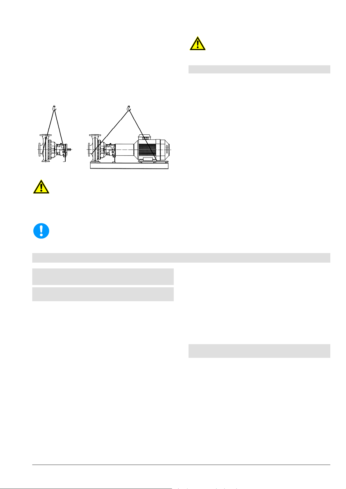
Das Anheben der Pumpe / des Aggregates darf
nur an stabilen Aufhängungspunkten wie
Gehäuse, Stutzen, Rahmen erfolgen. Bild 2 zeigt
die richtige Handhabung bei Krantransport.
Ein Herausrutschen der Pumpe / des
Aggregates aus der Transportauf hängung kann
Personen- und Sachschäden verursachen.
4.2 Zwischenlagerung / Konservierung
Pumpen oder Aggregate, die vor der Inbetr iebnahme
längere Zeit zwischengelagert werden (max. 6
Monate), vor Feuchtigkeit, Vibrationen und Schmutz
schützen (z.B. durch Einschlagen in Ölpapier oder
Kunststofffolie). Die Aufbewahrung hat grundsätzlich
an einem von äußeren Einflüssen geschützten Ort,
z.B. unter trockenem Dach, zu erfolgen. Während
dieser Zeit müssen Saug- und Druc kstutzen sowie alle
anderen Zu- und Ablaufstutzen immer mit
Blindflanschen oder Blindstopfen verschlossen
werden.
Leerstehende Pumpen
Mindestens 1x wöchentlich von Hand aus
Bild 2
Nicht unter schwebenden Lasten aufhalten,
allgemeine Unfallverhütungsvorschriften
beachten. Solange die Pumpe / das Aggregat
nicht am endgültigen Aufstellungsort befestigt
ist, muss es gegen Umkippen und Abrutschen
gesichert sein.
Die Anschlagseile dürfen nicht an freien
Wellenenden oder an Ringösen des Motors
befestigt werden.
durchdrehen (nicht einschalten wegen
Trockenlauf).
Nach 4 Jahren Lager tauschen.
Bei längeren Zwischenlagerungszeiten können
Konservierungsmaßnahmen an bearbeiteten
Bauteiloberflächen und eine Verpackung mit
Feuchtigkeitsschutz notwendig werden!
5. Aufstellung / Einbau
5.1 Aufstellung der Pumpe / des
Aggregates
5.1.1 Montage der Pumpe auf einer Fundamentplatte
Sofern nicht bereits vorhanden oder im Lieferumfang
enthalten, ist für Pumpe und Motor (= Aggregat) eine
gemeinsame Fundamentplatte aus Stahl oder
Grauguss bzw. aus verschweißten Stahlprofilen
erforderlich. Diese Fundamentplatte muss auf ein
Fundament gestellt werden, das allen während des
Betriebes entstehenden Belastungen standhält (siehe
Kapitel 5.1.2).
Bei der Montage der Pumpe auf die Fundamentplatte
ist folgendes zu beachten:
Die Fundamentplatte muss so stabil ausgeführt
sein, dass es im Betrieb zu k einen Verwindungen
und unzulässigen Schwingungen (Resonanzen)
kommt.
Die Aufstellflächen der Pumpenfüße und des
Motors an der Fundamentplatte müssen eben sein
(mechanische Bearbeitung wird empfohlen). Ein
Verspannen der Pumpe führt zum vorzeitigen
Ausfall und zum Erlöschen eines jeglichen
Garantieanspruches.
Die Bohrungen zur Pumpenbefestigung müssen
so ausgeführt werden, dass ein sicheres
Befestigen ermöglicht wird.
Seite 9
Zwischen Pumpen- und Motorwelle ist ein von der
verwendeten Kupplung abhängiger Abstand
einzuhalten, siehe auch Kapitel 5.3.
Zwischen Pumpe und F undamentplatte muss ein
entsprechender Höhenausgleich vorhanden sein,
damit bei Ersatz der Pumpe wieder die gleiche
Achshöhe eingestellt werden kann (empfohlener
Höhenausgleich 4-6 mm).
Pumpe und Motor ausrichten, siehe auch Kapitel
5.3.
5.1.2. Aufstellung des Aggregates auf ein
Fundament
Die Bauwerkgestaltung muss gemäß den
Abmessungen der Maßzeichnung vorbereitet s ein. Die
Betonfundamente sollen eine ausreichende
Betonfestigkeit nach DIN 1045 oder gleichwertiger
Norm (min. BN 15) haben, um eine sichere,
funktionsgerechte Aufstellung zu ermöglichen.
Das Betonfundament m uss abgebunden haben, bevor
das Aggregat aufgesetzt wird. Seine Oberfläche m uss
waagrecht und eben sein.
Page 14
Einbau-, Betriebs- und Wartungsanleitung Baureihe L, LN
A
A
Für Wartung und Instandhaltung ist genügend
Raum vorzusehen, besonders für das
uswechseln des Antriebsmotors oder des
kompletten Pum penaggregates. Der Lüfter des
Motors muss genügend Kühlluft ansaugen
können. Daher ist mindestens 10 cm Abstand
des Ansauggitters zu einer Wand, etc.
erforderlich.
Für die Fundamentanker sollen entsprechende
Aussparungen vorgesehen werden. Ist dies nicht
der Fall, können Spreizanker bzw. Klebeanker
verwendet werden.
Das Aggregat ist beim Aufsetzen auf das
Fundament mit Hilfe einer Wasserwaage (am
Druckstutzen der Pumpe) auszurichten. Die
zulässige Lageabweichung beträgt 0,2 mm/m.
Nach Einsetzen der Fundamentschrauben sind
diese mit Beton in das Fundament einzugießen.
Nach Abbinden der Vergussmasse muss die
Kupplungsausrichtung entsprechend Kapitel 5.3.1
überprüft werden und etwaige Fehlstellungen
durch Ausrichten der Fundam entplatte im Bereich
des Antriebsmotors ausgeglichen werden. Die
Ebenheit der Fundamentplatte muss vor dem
Ausgießen 0,2 mm/m betragen. Zum Ausrichten
können Unterlegbleche oder Nivellierschrauben
(optional, nicht im Standard-Lieferumfang
enthalten) verwendet werden. Die Unterlagsbleche
müssen in unmittelbarer Nähe der
Fundamentanker eingesetzt werden und müssen
alle plan aufliegen. Anschließend die
Fundamentschrauben gleichmäßig und nur leicht
anziehen. Die Fundamentplatte mit möglichst
schwindungsfreiem Vergussbeton ausgießen.
Dabei ist zu beachten:
Hohlräume vermeiden (z.B. durch rütteln).
Einwandfreie Abbindung und Aushärtung
kontrollieren.
Es ist dringend auf die Betonnachbehandlung
nach DIN 1045 zu achten.
Nach dem Abbinden des Vergussbetons
Fundamentanker gleichmäßig und fest anziehen.
Ausrichtung der Kupplung entspr echend Kapitel 5.3.1
kontrollieren und gegebenenfalls nachrichten, sowie
sämtliche Verbindungsschrauben von Pumpe und
Motor zur Fundamentplatte auf festen Sitz
kontrollieren.
Werden von benachbarten Anlagenbauteilen
Schwingungen auf das Pumpenfundament
übertragen, muss dieses durch entsprechende
schwingungsdämpfende Unterlagen abgeschirmt
werden (Schwingungen von außen können die
Lagerung beeinträchtigen).
Soll die Übertragung von Schwingungen auf
benachbarte Anlagenbauteile vermieden werden,
ist das Fundament auf entsprechende
schwingungsdämpfende Unterlagen zu gründen.
Seite 10
Die Dimensionierung dieser schwingungsisolierenden Unterlagen ist für jeden
nwendungsfall verschieden und soll daher von
einem erfahrenen Fachmann durchgeführt
werden.
5.2 Anschluss der Rohrleitungen an die
Pumpe
Die Pumpe darf auf keinen Fall als Festpunkt
für die Rohrleitung verwendet werden. Die
zulässigen Rohrleitungskräfte dürfen nicht
überschritten werden, siehe Kapitel 3.5.
5.2.1 Saug- und Druckleitung
Die Rohrleitungen müssen so bemessen und
ausgeführt sein, dass eine einwandfreie
Anströmung der Pumpe gewährleistet ist und
daher die Funktion der Pumpe nic ht beeinträchtigt
wird. Besonderes Augenmerk ist auf die
Luftdichtheit von Saugleitungen und Einhaltung
der NPSH-Werte zu legen. Bei Saugbetrieb die
Saugleitung im horizontalen Teil zur Pumpe leicht
steigend verlegen, so dass keine Luftsäcke
entstehen. Bei Zulaufbetrieb die Zulaufleitung
leicht fallend zur Pumpe verlegen. Keine
Armaturen oder Krümmer unmittelbar vor dem
Pumpeneintritt vorsehen.
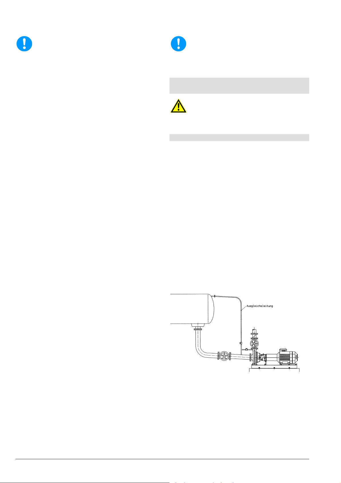
Bei Förderung aus unter Vakuum stehenden
Behältern ist die Anordnung einer
Vakuumausgleichsleitung vorteilhaft. Die
Rohrleitung soll eine Mindestnennweite von 25
mm aufweisen und muss über dem höchsten im
Behälter zulässigen Flüssigkeitsstand münden.
Eine zusätzliche absperrbare Rohrleitung (Bild 3) -
Pumpendruckstutzen-Ausgleichsleitung erleichtert das Entlüften der Pumpe vor dem
Anfahren.
Bild 3
Achten Sie bei der Leitungsführung auf die
Zugängigkeit zur Pumpe bezüglich Wartung,
Montage, Demontage und Entleerung.
"Zulässige Stutzenkräfte und Momente an den
Pumpenstutzen ..." (Kapitel 3.5) beachten.
Wenn in den Rohrleitungen Kompensatoren
verwendet werden, so sind diese so abzufangen,
dass die Pumpe nicht durch den Druck in der
Rohrleitung unzulässig hoch belastet wird.
Vor Anschluss an die Pumpe: Schutz-
abdeckungen der Pumpenstutzen entfernen.
Page 15
Einbau-, Betriebs- und Wartungsanleitung Baureihe L, LN
A
A
f
r
r
Vor Inbetriebnahme muss das Rohrsystem,
installierte Armaturen und Apparate von
Schweißperlen, Zunder usw. gereinigt werden.
Anlagen, die in direktem oder indirektem
Zusammenhang mit Trinkwassersystemen
stehen, sind vor Einbau und Inbetriebnahme von
eventuellen Verunreinigungen sicher zu befreien.
Zum Schutz der W ellenabdichtung (insbesondere
Gleitringdichtungen) vor Frem dkörpern em pfohlen
im Anfahrbetrieb: Sieb 800 Mikron in Saug- /
Zulaufleitung.
Wird das Rohrsystem mit eingebauter Pumpe
abgedrückt, dann: maximal zulässigen
Gehäuseenddruck der Pum pe bzw. der W ellenabdichtung beachten, siehe Datenblatt und / oder
der Auftragsbestätigung.
Bei Entleerung der Rohrleitung nach Druckprobe
Pumpe entsprechend konservieren (sonst
Festrosten und Probleme bei Inbetriebnahme).
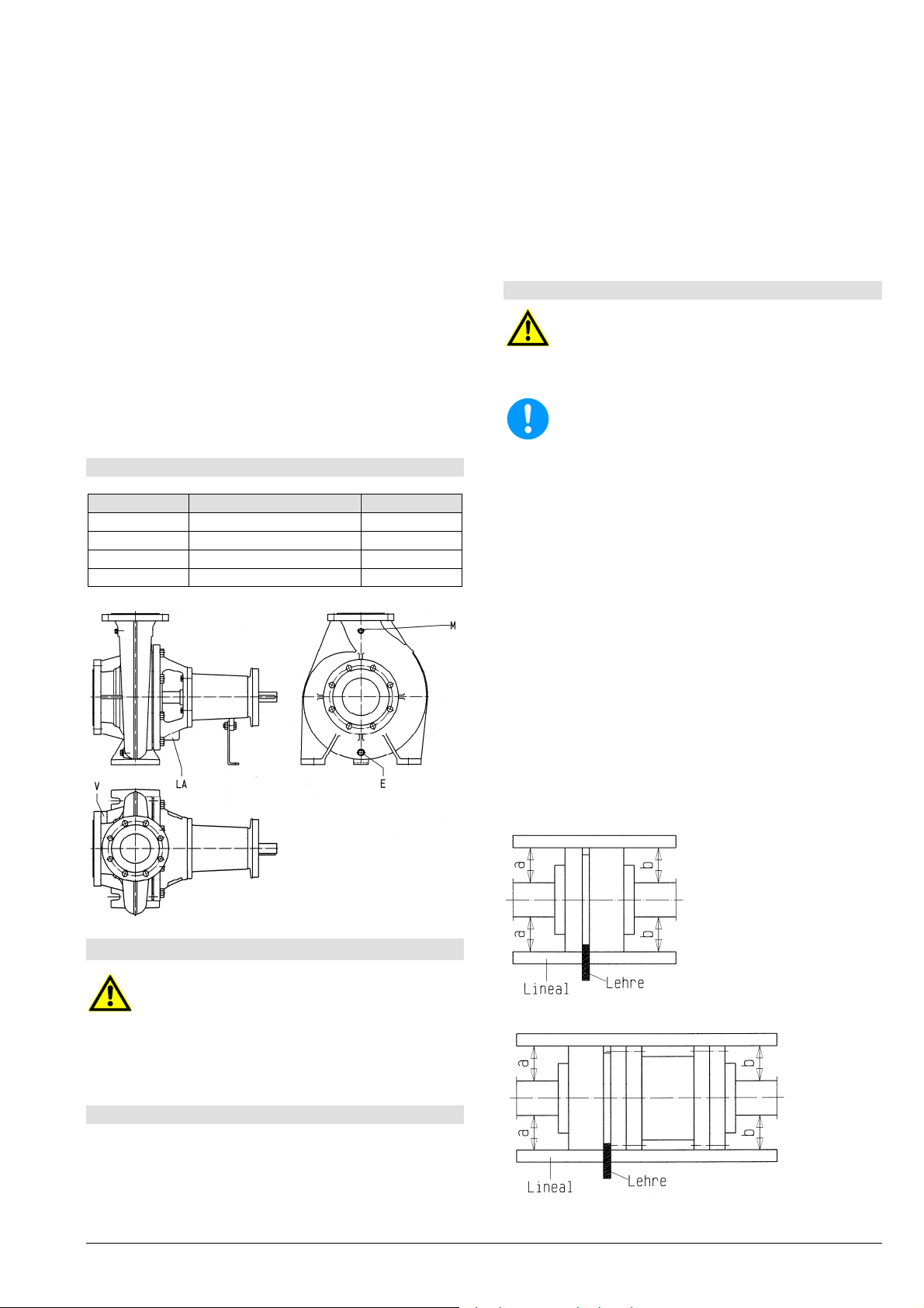
5.2.2 Zusatzanschlüsse
Folgende Zusatzanschlüsse sind vorhanden:
Anschluss Beschreibung Dimension
E Entleerung der Pumpe R3/8"
LA Leckflüssigkeit R1/2"
M Manometer R1/4"
V*) Vakuummeter*) R1/4"
*) ... optional, auf Wunsch gebohrt
Kupplung auf Wellenende aufziehen, nicht
schlagen. Vorheriges Erwärm en der Kupplung im
Ölbad auf etwa 100°C ist möglich (erleichtertes
Aufziehen). Gummipakete vorher aus
Kupplungsteil herausnehmen.
Die Kupplungsteile müssen mit den
Wellenstirnflächen bündig sein.
Mit radialen Gewindestiften Kupplungsnaben
gegen axiale Verschiebung sichern.
5.3.2 Ausrichten der Kupplung
Das Ausrichten muss mit größter Sorgfalt
vorgenommen werden, da dies Voraussetzung
für einen störungsfreien Betr ieb des Aggregates
ist. Das Nichtbeachten dieser Hinweise führt
zum Verlust aller Garantieansprüche!
uch bei komplett auf Rahmen montiert
gelieferten Aggregaten: Nach der Montage au
das Fundament und dem Anschluss de
Rohrleitungen ist ein neuerliches Ausrichten de
Kupplung erforderlich.
Vor dem Ausr ichten der Kupplung Sc hrauben (S7;
M7) zwischen Lagerträger (10) und Stützfuß
(80/F) lockern und erst nach dem Ausrichten
wieder festziehen. Nach dem Festziehen der
Schrauben (S7; M7) die Messung noch einmal
wiederholen.
Das Aggregat ist richtig ausgerichtet, wenn ein
über beide Kupplungshälften axial gelegtes Lineal
überall auf dem Um fang gleic hen Abstand von der
jeweiligen Welle hat. Ferner müssen beide
Kupplungshälften überall am Umfang gleichen
Abstand voneinander haben. Dies ist mit Taster,
Lehre oder Messuhr nachzuprüfen; siehe Bild 4
und 5.
Den zulässigen Versatz für Ihre Kupplung siehe
Kapitel 5.5.3 "Zulässiger Versatz bei elastischen
Kupplungen". Die genaue Bezeichnung Ihrer
Kupplung finden Sie auf dem Datenblatt und /
oder der Auftragsbestätigung.
5.3 Kupplung
Sicherstellen, dass während der Arbeiten bei
fehlendem Kupplungsschutz die Antriebsmaschine nicht in Betrieb gesetzt werden kann.
Bild 4 - Ausrichten der Kupplung mit Lehre und Lineal
Gemäß Unfallverhütungsvorschriften darf das
ggregat nur mit montiertem Kupplungsschutz
betrieben werden.
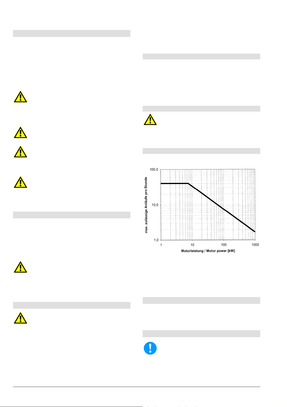
5.3.1 Montage der Kupplung
Wird das Aggregat erst am Einsatzort komp lettiert, so
ist bei der Montage der Kupplung folgendermaßen
vorzugehen:
Vor Beginn der Montage Wellenenden und
Kupplungsteile sorgfältig reinigen.
Seite 11
Bild 5 - Ausrichten der Kupplung mit Ausbaustück
Page 16
Einbau-, Betriebs- und Wartungsanleitung Baureihe L, LN
A
A
r
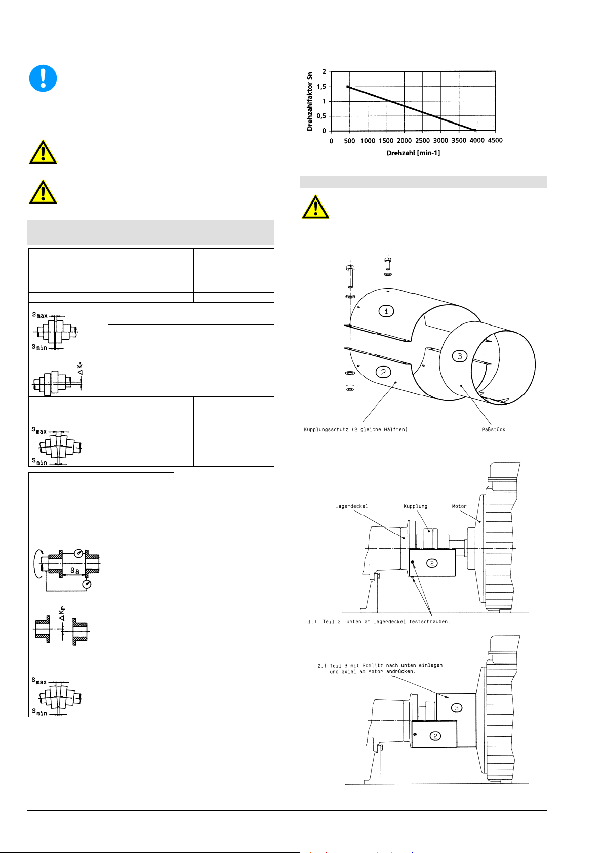
5.3.3 Zulässiger Versatz bei elastischen Kupplungen
Kupplungsgröße
Kupplungs-Außen [mm]
Axialer Abstand S
usrichtung der Kupplung im betriebswarmen
Zustand und bei Systemdruck (f alls vorhanden)
noch einmal kontrollieren und gegebenenfalls
korrigieren. Vorher Kapitel 6 beachten! Das
ggregat muss sich von Hand aus leicht und
gleichmäßig durchdrehen lassen.
Unsachgemäßes Ausrichten des Aggregates
kann zu Schäden an Kupplung und Aggregat
führen!
Nach dem Ausrichten und vor de
Inbetriebnahme Kupplungsschutz montieren.
H80FK
H95FK
H110FK
B125KF
H125FK
B140FK
H140FK
B160FK
H160FK
B180FK
H180FK
B200FK
80 95 110 125 140 160 180 200
3 6
S
max
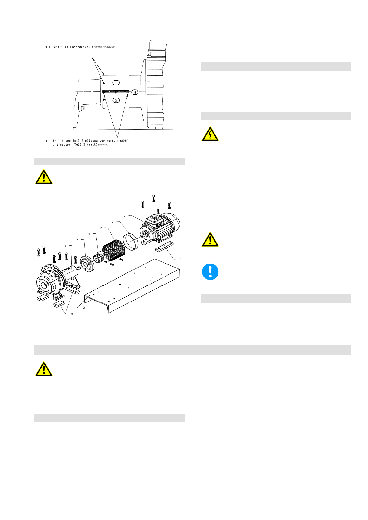
5.3.4 Kupplungsschutz Baureihe L
Gemäß Unfallverhütungsvorschriften darf die
Pumpe nur mit einem Kupplungsschutz
betrieben werden.
Bestandteile:
H200FK
S
min
Max. radialer Versatz Kr
min
max
- S
min
Max. winkeliger Versatz
. S
S
max
= S
K
w
Kupplungsgröße
Kupplungs-Außen [mm]
Axialer Abstand
Max. radialer Versatz Kr
Max. winkeliger Versatz
. S
S
max
min
= S
K
w
max
- S
min
2
0,1 0,2
0,1 0,2
NHN160FK
NHN180FK
NHN200FK
168 180 200
0,3
0,4
0,2
0,2
Montage:
S8 = Nennlänge der Ausbaukupplung
Die angegebenen Werte K
-1
.
min
und Kw gelten für 1500
r
Für alle anderen Drehzahlen gilt:
. Sn bzw. Kr . S
K
w
n
Seite 12
Page 17
Einbau-, Betriebs- und Wartungsanleitung Baureihe L, LN
r
r
f
r
Kupplungsscheibe (6) und den motorseitigen
Kupplungsring (7) festgeklemmt.
5.4 Antrieb
Bei der Auswahl der Motorgröße ist darauf zu achten,
dass die Anforderungen gem äß ISO 5199 erfüllt sind.
Die Betriebsanleitung des Motorherstellers ist zu
beachten.
5.5 Elektrischer Anschluss
Der Elektroanschluss darf nur durch einen
befugten Elektrofachmann erfolgen. Die in de
5.3.5 Kupplungsschutz Baureihe LN
Gemäß Unfallverhütungsvorschriften darf die
Pumpe nur mit einem Kupplungsschutz
betrieben werden.
Elektrotechnik gültigen Regeln und Vorschriften,
insbesondere hinsichtlich Schutzmaßnahmen
sind zu beachten. Die Vorschriften der örtlic hen
nationalen Energieversorgungsunternehmen
sind ebenso einzuhalten.
Vor Beginn der Arbeiten die Angaben auf dem
Motorleistungsschild auf Übereinstimmung mit dem
örtlichen Stromnetz überprüfen. Das Anklemmen der
Stromzuführungskabel des gekuppelten Antriebsmotors ist entsprechend dem Schaltplan des
Motorherstellers vorzunehmen.
Ein Motorschutzschalter ist vorzusehen.
Es ist dafür zu sorgen, dass der
Fundamentrahmen (2x M10-Gewinde fü
Erdungsschrauben vorhanden) mittels
entsprechender Maßnahmen geerdet wird.
Eine Überprüfung der Drehr ichtung darf nur bei
gefüllter Pumpe erfolgen. Jeder Trockenlau
führt zu Zerstörungen an der Pumpe.
5.6 Endkontrolle
Ausrichtung der Kupplung laut Kapitel 5.3.2 nochm als
Der Kupplungsschutz (5) wird durch Anziehen der
beiden unteren Schrauben auf die pumpenseitige
prüfen. Das Aggregat mus s sich an der Kupplung von
Hand leicht durchdrehen lassen.
6. Inbetriebnahme, Betrieb, Außerbetriebnahme
Die Anlage darf nur von Personal in Betrieb
genommen werden, das mit den örtlichen
Sicherheitsbestimmungen und mit diese
Betriebsanleitung (insbesondere mit den darin
enthaltenen Sicherheitsvorschriften und
Sicherheitshinweisen) vertraut ist.
6.1 Erstinbetriebnahme
Vor dem Einschalten der Pumpe muss sichergestellt
sein, dass nachstehende Punkte geprüft und
durchgeführt wurden:
Pumpe und Saugleitung müssen bei
Inbetriebnahme vollständig mit Flüssigkeit gefüllt
sein.
Aggregat noch einmal von Hand aus durchdrehen
und leichten, gleichmäßigen Gang prüfen.
Seite 13
Kontrollieren, ob Kupplungsschutz montiert ist und
alle Sicherheitseinrichtungen betriebsbereit sind.
Schieber in Saug- bzw. Zulaufleitung öffnen.
Druckseitigen Schieber auf ca. 25% der
Auslegungs-Fördermenge eins tellen. Bei Pumpen
mit Druckstutzen-Nennweite kleiner DN 200 k ann
der Schieber beim Anfahren auch geschlossen
bleiben.
Sicherstellen, dass das Aggregat vors chrif tgerec ht
elektrisch mit allen Schutzeinrichtungen
angeschlossen ist.
Kurz Ein- und Ausschalten und dabei
Drehrichtung kontrollieren. Sie muss dem
Drehrichtungspfeil am Lagerträger entsprechen.
Page 18
Einbau-, Betriebs- und Wartungsanleitung Baureihe L, LN
r
r
r
r
A
/
r
6.2 Antriebsmaschine einschalten.
Sofort (max . 30 Sekunden bei 50 Hz bzw. max. 20
Sekunden bei 60 Hz Stromversorgung) nach dem
Hochlauf auf die Betriebsdrehzahl druckseitigen
Schieber öffnen und damit den gewünschten
Betriebspunkt einstellen. Die am Typenschild bzw.
im Datenblatt und / oder der Auftragsbestätigung
angegebenen Förderdaten müssen eingehalten
werden. Jede Änderung ist nur nach Rücksprac he
mit dem Hersteller zulässig!
Damit die Wellenabdichtung ungehindert
beobachtet und gewartet werden kann, ist in
diesem Bereich keine Schutzabdeckung
vorhanden. Bei laufender Pumpe ist dahe
besondere Vorsicht erforderlich (keine langen
Haare, lose Kleidungsstücke, usw.).
Der Betrieb mit geschloss enem Absperrorgan in
der Saug- und / oder Druckleitung ist nicht
zulässig.
Bei Anfahren gegen fehlenden Gegendruck ist
dieser durch druckseitiges Drosseln
herzustellen (Schieber nur wenig öffnen). Nach
Erreichen des vollen Gegendruckes Schiebe
öffnen.
Pumpe und Antriebsm aschine sollen gleichmäßig
und erschütterungsfrei laufen, mindestens
wöchentlich kontrollieren.
6.4.1 Förderstrom min. / max.
Sofern in den Kennlinien oder Datenblättern keine
anderen Angaben gemacht sind, gilt:
= 0,1 x Q
Q
min
= 0,3 x Q
Q
min
= 1,2 x Q
Q
max
Q
= Förderstrom im Wirkungsgradoptimum
BEP
*) unter der Voraussetzung NPSH
für Kurzzeitbetrieb
BEP
für Dauerbetrieb
BEP
für Dauerbetrieb *)
BEP
Anlage
> (NPSH
Pumpe
+ 0,5 m)
6.4.2 Abrasive Medien
Beim Fördern von Flüssigkeiten mit abrasiven
Bestandteilen ist ein erhöhter Verschleiß an
Hydraulik und Wellenabdichtung zu erwarten.
Die Inspektionsintervalle sollen gegenüber den
üblichen Zeiten reduziert werden.
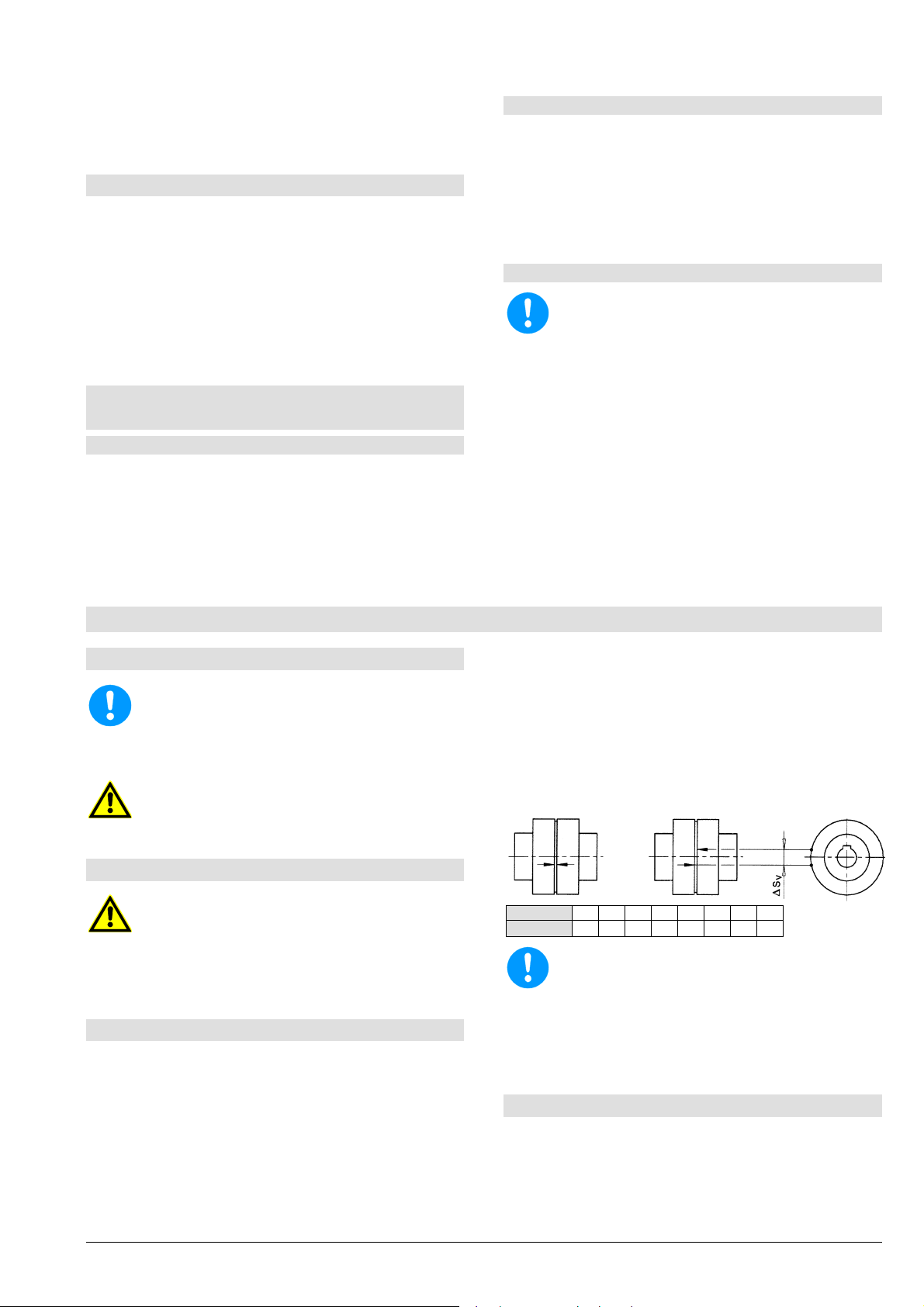
6.4.3 Zulässige Schalthäufigkeit
Die zulässige Schalthäufigkeit der Pumpe darf nicht
überschritten werden, siehe Diagramm 6.
Erreicht die Pumpe nicht die vorgesehene
Förderhöhe oder treten atypische Geräusche
oder Schwingungen auf: Pumpe wieder auße
Betrieb setzen (siehe Kapitel 6.7) und Ursache
suchen (siehe Kapitel 10).
6.3 Wiederinbetriebnahme
Bei jeder W iederinbetriebnahme ist grundsätzlich wie
bei der Erstinbetriebnahme vorzugehen. Die Kontrolle
von Drehrichtung und Leichtgängigkeit des
Aggregates kann jedoch entfallen.
Eine automatische Wiederinbetriebnahme darf nur
dann erfolgen, wenn sichergestellt ist, dass die Pumpe
bei Stillstand mit Flüssigkeit gefüllt bleibt.
Besondere Vorsicht vor Berührung heiße
Maschinenteile und im ungeschützten Bereich
der Wellenabdichtung. Automatisch gesteuerte
nlagen können sich jederzeit und
überraschend einschalten. Anlagenseitig
entsprechende Warnschilder anbringen.
6.4 Grenzen des Betriebes
Die Einsatzgrenzen der Pumpe / des
Aggregates bezüglich Druck, Temperatur,
Leistung und Drehzahl sind im Datenblatt und
oder der Auftragsbestätigung angegeben und
unbedingt einzuhalten!
Die auf dem Typenschild der Antriebsmaschine
angegebene Leistung darf nicht überschritten
werden.
Plötzlich auftretende Temperaturänderungen
(Temperaturschocks) sind zu vermeiden.
Seite 14
Diagramm 6
Bei Elektromotoren ist die zulässige Schalthäufigkeit
der beiliegenden Motorbetriebsanleitung zu
entnehmen.
Bei von einander abweichenden Werten ist die
kleinere Schalthäufigkeit zulässig.
6.5 Fettschmierung
Die Pumpe ist mit auf Lebensdauer fettgeschmierten
Lagern ausgestattet. Ein Nachschm ieren der Lager ist
weder möglich noch erforderlich.
6.6 Überwachung
Regelmäßig durchgeführte Überwachungs - und
Wartungsarbeiten verlängern die Lebensdaue
Ihrer Pumpe oder Anlage.
Pumpen, die funktionsbedingt einem chemischen
Angriff bzw. abrasiven Verschleiß ausgesetzt sind,
müssen periodisch auf chemischen oder abrasiven
Abtrag inspiziert werden. Die Erstinspektion ist nach
Page 19
Einbau-, Betriebs- und Wartungsanleitung Baureihe L, LN
r
r
einem halben Jahr durchzuführen. Alle weiteren
Inspektionsintervalle sind auf Grund des jeweiligen
Zustandes der Pumpe festzulegen.
6.7 Außerbetriebnahme
Sc hieber in der Druckleitung unmittelbar (max. 10
Sekunden) vor Abschaltung des Motors sch ließen.
Nicht erforderlich, wenn druckbelastete
Rückschlagklappe vorhanden ist.
Antriebsmasc hine absc halten. Auf r uhigen Auslauf
achten.
Schieber auf der Saugseite schließen.
Bei Frostgefahr Pumpe, Kühlr äum e und Leitungen
vollständig entleeren.
6.8 Zwischenlagerung / Längerer Stillstand
6.8.1 Zwischenlagerung neuer Pumpen
Wenn die Inbetriebnahme längere Zeit nach der
Lieferung erfolgen soll, empfehlen wir zur
Zwischenlagerung der Pumpe die folgenden
Maßnahmen:
Pumpe an einem trockenen Ort lagern.
Durchdrehen der Pumpe von Hand einmal
6.8.2 Maßnahmen für längere Außerbetriebnahme
Pumpe bleibt eingebaut mit Betriebsbereitschaft:
In regelmäßigen Abständen sind Probeläufe von
einer Dauer von mindestens 5 Minuten
durchzuführen. Die Zeitspanne zwischen den
Probeläufen hängt von der Anlage ab, sollte
jedoch mindestens 1x pro Woche durchgeführt
werden.
6.8.3 Längerer Stillstand
Inbetriebnahme ist als Erstinbetriebnahme zu
verstehen (siehe Kapitel 6).
a) Gefüllte Pumpen
Reservepumpen 1x wöchentlich kurz ein- und
sofort wieder ausschalten. Eventuell alternativ als
Hauptpumpe betreiben.
Nach 4 Jahren Lager tauschen.
b) Leerstehende Pumpen
Mindestens 1x wöchentlich von Hand aus
durchdrehen (nicht einschalten wegen
Trockenlauf).
Nach 4 Jahren Lager tauschen.
monatlich.
7. Instandhaltung, Wartung
7.1 Allgemeine Hinweise
Instandhaltungsarbeiten und Wartung darf nu
von geschultem und erfahr enem Personal, das
mit dem Inhalt dieser Betr iebsanleitung vertraut
ist oder vom Service-Personal des Herstellers
durchgeführt werden.
Arbeiten an der Pumpe oder Anlage sind nur im
Stillstand durchzuführen. Beachten Sie
unbedingt Kapitel 2.
Markierung auf beiden Kupplungshälften aufgebracht
(siehe nachfolgende Abbildung). Durch Drehen des
Kupplungsteiles in die entgegengesetzte Drehrichtung
bis zum Anschlag wandern die Markierungen
auseinander und dieser Abstand ergibt das
Sehnenmaß S
Überschreitet dieses Maß den in der
v.
Tabelle angegebenen Wert, ist ein Austausch der
Pakete vorzunehmen. Die Pakete sind satzweise zu
wechseln.
7.2 Gleitringdichtungen
Vor dem Öf fnen der Pum pe unbedingt Kapitel 2
und Kapitel 3.2 beachten.
Tritt bei der Gleitringdichtung tropfenweise
Fördermedium aus, so is t diese beschädigt und mus s
ersetzt werden.
7.3 Kupplung
In regelmäßigen Abständen von ca. 1000
Betriebsstunden, mindestens aber 1x jährlich, ist das
Verdrehspiel in den Kupplungsteilen zu überprüfen.
Für Kupplungen mit Gummipaketen gilt:
So weit für den Betrieb ein geringes Verdr ehspiel der
Kupplung nicht erforderlich ist, können die
Kupplungspakete um c a. ¼ ihrer ur sprünglic hen Dick e
verschleißen, bevor sie auszuwechseln sind. Um das
Verdrehspiel (Sehnenmaß S
Kupplungsteil bis zum Anschlag gedreht und eine
Seite 15
) zu ermitteln, wird ein
v
Größe 80 95 110 125 140 160 180 200
Sv [mm]
5,0 6,0 7,0 8,0 8,5 8,0 8,0 8,5
Tritt in kurzer Zeit star ker Verschleiß auf, muss
davon ausgegangen werden, dass der Moto
mit der Pumpe nicht fluchtet oder der Abstand
der Kupplungshälften sich verändert hat.
Erneuern der Kupplungspakete und neuerliches
Montieren bzw. Ausrichten der Kupplung, wie in
Kapitel 5.3 beschrieben, erforderlich.
7.4 Reinigung der Pumpe
Äußerliche Verschmutzung an der Pumpe
beeinträchtigt die Wärmeabführung. Daher ist in
regelmäßigen Abständen (je nach
Verschmutzungsgrad) die Pumpe mit Wasser zu
reinigen.
Page 20
Einbau-, Betriebs- und Wartungsanleitung Baureihe L, LN
f
r
A
Die Pumpe darf nicht mit unter Druck
stehendem Wasser (z.B. Hochdruckreiniger)
gereinigt werden - Wassereintritt in Lager.
8. Demontage der Pumpe und Reparatur
8.1 Allgemeine Hinweise
Reparaturen an der Pum pe oder Anlage dürfen
nur von autorisiertem Fachpersonal oder durch
Fachpersonal des Herstellers durchgeführt
werden.
Bei Ausbau der Pumpe unbedingt Kapitel 2
sowie Kapitel 4.1 beachten.
Für Montagen und Reparaturen stehen auf
Anforderung geschulte Kundendienst-Monteure
zur Verfügung.
Pumpen, die gesundheitsgefährdende Flüssigkeiten fördern, m üssen dekontaminiert werden.
Beim Ablassen des Fördermediums ist darau
zu achten, dass keine Gefährdungen fü
Personen und Umwelt entsteht. Gesetzliche
Bestimmungen sind einzuhalten, ansonsten
besteht Lebensgefahr!
Vor Beginn der Demontage muss das Aggregat so
gesichert werden, dass es nicht eingeschaltet
werden kann.
Das Pum pengehäuse muss drucklos und entleert
sein.
Alle Absperrorgane in der Saug-, Zulauf- und
Druckleitung müssen geschlossen sein.
Alle Teile müssen Umgebungstemperatur
angenommen haben.
usgebaute Pumpe, Baugruppen oder
Einzelteile gegen Umkippen oder Wegrollen
sichern.
Offene Flamm e (Lötlampe, etc.) beim Zer legen
nur dann als Hilfe verwenden, wenn dadurch
keine Brand- oder Explosionsgefahr oder die
Gefahr der Entwicklung schädlicher Dämpfe
entsteht.
Nur Original-Ersatzteile verwenden. Auf
richtigen Werkstoff und passende Ausführung
achten.
8.2 Allgemeines
Demontage und Montage grundsätzlich nach der
zugehörigen Schnittzeichnung (im Anhang)
durchführen.
Es ist nur handelsübliches Werkzeug erforderlich.
Vor dem Zerlegen prüfen, ob die erforderlichen
Ersatzteile bereit liegen.
Die Pumpe immer nur so weit zerlegen, als dies für
den Austausch des zu reparierenden Teils erf orderlich
ist.
9. Ersatzteilempfehlung, Reservepumpen
9.1 Ersatzteile
Die Ersatzteile sind für die Bedingungen eines
zweijährigen Dauerbetriebes auszuwählen. Falls keine
anderen Richtlinien zu beachten sind, werden die in
unten angeführter Liste angegebenen Stück zahlen für
Ersatzteile empfohlen (nach DIN 24296).
Zur Sicherung einer optimalen Verfügbarkeit
empfehlen wir, auf Grund der längeren
Beschaffungszeiten entsprechende Ersatzteile
zu bevorraten.
Anzahl der Pumpen
Ersatzteile Stückzahl der Ersatztei l e
Laufrad 1 1 1 2 2 2 20%
Welle mi t Passfedern
und Muttern
Wälzlager Satz 1 1 2 2 2 3 25%
Dichtungen für
Pumpengehäuse Sätze
sonstige Dichtungen
Sätze
Gleitringdichtung Satz 1 1 2 2 2 3 25%
Lagerung (Lagerträger,
vollständig mit Welle,
Lagern, usw.)
(einschließlich Reservepumpen)
2 3 4 5 6/7 8/9 10/+
1 1 1 2 2 2 20%
4 6 8 8 9 12 150%
4 6 8 8 9 10 100%
- - - - - - 2
Ersatzteilbestellung
Bei Ersatzteilbestellung bitten wir Sie um folgende
Angaben:
Type: ______________________________________________________________________
S/N (Auftrags Nr.) ___________________________________________________
Teilebezeichnungen _______________________________________________
Schnittzeichnung ____________________________________________________
Alle Angaben finden Sie auf dem Datenblatt und / oder
der Auftragsbestätigung und der dazugehörigen
Schnittzeichnung.
Ersatzteile in trockenen Räumen und vor
Schmutz geschützt aufbewahren!
Seite 16
Page 21
Einbau-, Betriebs- und Wartungsanleitung Baureihe L, LN
9.2 Reservepumpen
Für Pumpen in Anlagen, deren Ausfall
Menschenleben gefährden bzw. hohe
Reservepumpen entsprechend Kapitel 6.8
aufbewahren!
Sachschäden oder Kosten verursachen können,
ist unbedingt eine ausreichende Anzahl von
Reservepumpen in der Anlage betriebsbereit zu
halten. Die Betriebsbereitschaft ist durch
laufende Kontrolle sicherzustellen, siehe Kapitel
6.8.
10. Störungen - Ursachen und Behebung
Die angeführten Hinweise auf Ursachen und
Behebung von Störungen sollen zur Erkennung des
Problems dienen. Für Störungen, die der Betreiber
nicht selbst beseitigen kann oder will, steht der
Kundendienst des Herstellers zur Verfügung. Bei
den Betreiber sind besonders die Auslegungsdaten
auf dem Datenblatt und / oder der Auftragsbes tätigung
sowie Kapitel 2 dieser Betriebsanleitung zu beachten.
Gegebenenfalls ist das sch riftliche Einverständnis des
Herstellers einzuholen.
Reparaturen und Änderungen an der Pumpe durch
Förderstrom zu gering
Förderstrom hört nach einiger Zeit auf
Förderhöhe zu gering
Förderhöhe zu hoch
Antriebsmaschine überlastet
Unruhiger Lauf der Pumpe
Zu hohe Temperatur in der Pumpe
Zu hohe Temperatur an der
■
Gegendruck zu hoch Anlage auf Verunreinigungen überprüfen, Schieber geöffnet
■
■ ■
■ ■
■ Förderstrom zu groß Fördermenge verringern (Schieber drosseln)
■ ■
■ ■
■ ■ ■
■ ■
■ ■ ■
■ ■ ■
■ ■ ■
■ ■
■ ■
■ ■ ■
■ ■Riefen und Rauhigkeit an Welle Teile erneuern
■ ■Ablagerungen an Gleitringdichtung reinigen
■ ■Unwucht des Laufrades Verstopfungen / Ablagerungen beseitigen
■
■
■
■ ■
Drehzahl zu hoch Drehzahl verringern
Drehzahl zu klein Drehzahl erhöhen (verfügbare Antriebsleistung beachten)
■ ■
■ ■
Laufraddurchmesser zu groß kleineres Laufrad verwenden
Laufraddurchmesser zu klein größeres Laufrad verwenden (verfügbare Antriebsleistung
■ ■
Pumpe oder Saug- / Zulaufleitung verstopft reinigen
Luftsack in Rohrleitung entlüften
■ ■
Luft wird angesaugt Flüssigkeitsspiegel erhöhen
Ansaugen von Luft durch die Wellenabdichtung Sperrleitung reinigen
Drehrichtung falsch Zwei Phasen der Stromzuführung vertauschen (vom
■
Dichte und / oder Viskosität des Fördermediums zu hoch Rückfrage erforderlich
Wellendichtung
■
Förderstrom zu klein Mindestfördermenge vergrößern (Schieber öffnen, Bypass)
Pumpe und / oder Rohrleitung nicht völlig mit Flüssigkeit
Saughöhe zu groß / NPSH der Anlage zu klein Flüssigkeitsspiegel erhöhen
■
■
■
Ursache
Zu hohe Temperatur an der Lagerung
Undichtheit an der Pumpe
Zu starke Leckage der Wellendichtung
Gegendruck zu gering, Förderstrom zu groß druckseitigen Schieber drosseln
gefüllt
Verschleiß der Innenteile abgenützte Teile erneuern
■
Kupplung fluchtet nicht Aggregat besser ausrichten
Kupplungsabstand zu klein ändern
Behebung
Widerstände in der Druckleitung vermindern (Filter reinigen, ...)
größeres Laufrad verwenden (Antriebsleistung beachten)
Drehzahl der Antriebsmaschine mit vorgeschriebener
Pumpendrehzahl (Leistungsschild) vergleichen
Bei Drehzahlregelung (Frequenzumformer) SollwertEinstellung kontrollieren
Drehzahl der Antriebsmaschine mit vorgeschriebener
Pumpendrehzahl (Leistungsschild) vergleichen
Bei Drehzahlregelung (Frequenzumformer) SollwertEinstellung kontrollieren
beachten)
füllen
entlüften
Leitungsführung verbessern
Vordruck erhöhen
Widerstände der Zulauf- / Saugleitung verri ngern (Verlauf und
Nennweite ändern, Absperrorgane öffnen, Siebe reinigen)
Vakuumdichtheit der Saugleitung prüfen und herstellen
Wellenabdichtung erneuern
Elektrofachmann durchzuführen)
gegebenenfalls Gleitringdichtung erneuern
ev. Laufrad erneuern; Welle auf Rundlauf prüfen
Seite 17
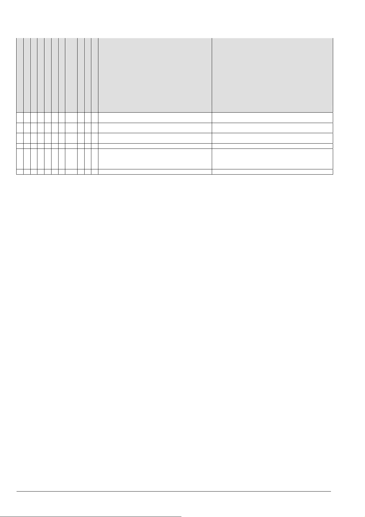
Page 22
Einbau-, Betriebs- und Wartungsanleitung Baureihe L, LN
Förderstrom zu gering
Förderstrom hört nach einiger Zeit auf
Förderhöhe zu gering
Förderhöhe zu hoch
Antriebsmaschine überlastet
Unruhiger Lauf der Pumpe
Zu hohe Temperatur in der Pumpe
Zu hohe Temperatur an der
Wellendichtung
■ ■ ■
■ Elektrische Anspeisung nicht korrekt (2-Phasenlauf) Spannung aller Phasen kontrollieren
■ Dichtung unzureichend Schrauben nachziehen
■ ■ Lager schadhaft erneuern
■ Entlastungseinrichtung ungenügend Entlastungsbohrungen im Laufrad reinigen
■ Anlagenbedingte Schwingungen Rückfrage erforderlich
■ ■
Ursache
Zu hohe Temperatur an der Lagerung
Undichtheit an der Pumpe
Zu starke Leckage der Wellendichtung
Rohrleitungskräfte zu hoch (Aggregat verspannt) ändern (Rohrleitungen abfangen, Kompensatoren, etc.)
Behebung
Fundamentplatte / Rahmen korrekt montiert / vergossen?
Kabelanschlüsse bzw. Sicherungen prüfen
Dichtung erneuern
abgenützte Teile ersetzen (Laufrad)
an den bei Bestellung angegebenen Systemdruck /
Zulaufdruck angleichen
Seite 18
Page 23

Einbau-, Betriebs- und Wartungsanleitung Baureihe L, LN
A
A
r
r
11. Motorbetriebsanleitung
Die nachstehenden Anweisungen sind genau zu
befolgen, um die Sic herheit bei der Installation,
beim Betrieb und bei der Wartung des Motors
zu gewährleisten. Alle Personen, die mit diesen
ufgaben befaßt sind, sind auf die vorliegende
nleitung hinzuweisen. Die Nichtbefolgung de
hierin enthaltenen Anweisungen kann den
Verlust der Gewährleistung zur Folge haben.
Stromanschluss
Vergewissern Sie sich, dass die auf dem
Leistungsschild angegebene Spannung den
Werten Ihres Speisenetzes entspricht.
Die Erdung vor allen anderen Anschlüssen
vornehmen.
Es empfiehlt sich der Einbau eines
hochsensiblen Fehlerstrom -Schutzschalters (30
mA) als zusätzlicher Schutz gegen
lebensgefährliche Stromstöße im Falle eine
fehlerhaften Erdung.
Den Netzanschluss mit einem allpoligen Schalter oder
einer anderen Vorrichtung, die die allpolige
Netzausschaltung sichert (also alle Speiseleitungen
unterbricht) und einen Abstand der Öffnungskontakte
von mindestens 3 mm aufweist, vornehmen.
Die Abdeckung des Klemm enbretts abnehm en, indem
man die Befestigungsschrauben aufschraubt. Die
Verbindungen wie auf der Rückseite der
Klemmenbrettabdeckung angegeben bzw. in
Abbildung 3 - 4.
Die Wechselstromausführung hat einen eingebauten
Überlastschutz, während die Drehstromausführung
kundenseitig gesichert werden muss. Verwenden Sie
dazu einen magnetothermischen Motorschutzschalter
oder einen Anlasser komplett mit Fernschalter,
Thermorelais und vorgelagerter Schmelzsicherung.
Das Überstromrelais ist auf dem Nennstrom des
Motors entsprechend dem Leistungsschild
einzustellen.
Das Thermorelais kann auf einen leicht niedrigeren
Wert als den der Volllast eingestellt werden, wenn die
Motorpumpe sicher nicht voll ausgelastet wird;
hingegen darf der Thermoschutz nicht auf einen
höheren Wert als den Nennstrom eingestellt werden.
Kontrolle der Drehrichtung bei Elektropumpen mit
Drehstrommotoren
Die Kontrolle der Drehrichtung k ann vor dem Anfüllen
der Pumpe mit der zu pumpenden Flüssigkeit
erfolgen, vorausgesetzt, dass man die Pumpe nur
kurz drehen lässt.
Der Betrieb der Pumpe vor dem Anfüllen mit
der Flüssigkeit ist nicht zulässig.
Kontinuierlicher Trockenlauf beschädigt die
Gleitringdichtung.
Ist die Drehrichtung nicht entgegen dem Uhrzeigersinn
(von der Seite des Saugstutzens gesehen), so sind
zwei Speisedrähte umzustecken.
Störungssuche
Störung Mögliche Ursache Abhilfe
1. Die Pumpe startet
nicht
2. Überlastschutz
spricht an:
- zufällig
- systematisch C) Falsche
A) Spannungsabfall
im Netz
B) Sicherungen
durchgebrannt
B1 Ungeeignete
Sicherungen
(Ansprechstrom zu
niedrig)
B2 Motor oder
Speisekabel
beschädigt
C) Überlastschutz hat
eingegriffen
A) Momentaner
Ausfall einer Phase
Einstellung des
Motorschutzschalters
D) Zu hohe
Fördermenge
E) Die Dichte oder
Viskosität der
Flüssigkeit
übersteigen die
Grenzwerte
A) Stromversorgung
sicherstellen
B1 Geeignete
Sicherungen
einbauen
B2 Motor reparieren
oder Kabel
austauschen
C) Überlastschutz
rückstellen (bei
erneutem Ausfall
siehe Punkt 2)
C) Auf den
Nennstrom des
Leistungsschildes
einstellen
D) Druckventil
schließen, bis die
Fördermenge dem
Arbeitsbereich der
Pumpe entspricht
E) Effektiv
erforderliche
Motorleistung
bestimmen und Motor
entsprechend
ersetzen
Lagerung und Lagerschmierung
Motoren mit dauergeschmierten Lagern
Bis zur Achshöhe 180 sind die Motoren in der Regel
mit dauergeschmierten Lagern der Typen 2Z oder
2RS ausgestattet.
Motoren mit Nachschmiereinrichtung der
Baugrößen 200 - 355
Schmieren Sie den Motor mit einer Fettpresse über
Schmiernippel während des Laufs. Vor der
Nachschmierung sind die Schmiernippel zu reinigen.
Die Motoren sind mit einer Entlastungsbohrung
versehen.
Wenn der Motor mit einem Fettauslass-Stopfen
versehen ist, muß dieser während des
Nachschmierens entfernt sein - bei selbsttätig
wirkenden Nachschmiersystemen ist die
Auslassöffnung permanent offen zu halten.
Wenn der Motor mit Nachschmierschild versehen ist,
folgen Sie bitte diesen Angaben. Im übrigen gelten die
nachfolgenden Angaben
Drehzahl Laufzeit [h] Kalenderzeit
[1/min]
Nachschmieren
[Monate]
max. 1800 1.500 6
über 1800 750 3
Drehzahl Laufzeit [h] Kalenderzeit
[1/min] Auswechseln [Monate]
max. 1800 10.000 24
über 1800 5.000 12
Seite 19
Page 24

Einbau-, Betriebs- und Wartungsanleitung Baureihe L, LN
Die in der Tabelle angegebenen Wartungsintervalle
basieren auf Standardumgebungsbedingungen.
Lebensdauer der Rillenkugellager
Für die Baugröße 56 - 180 beträgt diese ca. 20000
Betriebsstunden.
Seite 20
Page 25

Instructions de montage, de service et de maintenance Série L, LN
SOMMAIRE
Plaque signalétique de la pompe ... ...................... 22
5.5 Raccordement électrique ................................. 33
5.6 Contrôle final .................................................... 33
1. Généralités .......................................................... 23
1.1 Garantie........................................................... 23
2. Règles de sécurité .............................................. 23
2.1 Identification des consignes dans les
instructions de service ........................................... 23
2.2 Dangers en cas d’inobservation des consignes
de sécurité ............................................................. 24
2.3 Consignes de sécurité destinées à l’exploitant /
l’opérateur ............................................................. 24
2.4 Consignes de sécurité pour les travaux de
maintenance, d’inspection et de montage ............. 24
2.5 Modifications arbitraires et fabrication de pièces
détachées .............................................................. 24
2.6 Modes de fonctionnement inadmissibles ........ 24
2.7 Utilisation selon les réglementations ............... 25
3. Description de l’exécution ................................. 25
3.1 Pompes ........................................................... 25
3.2 Pressions de service max. admissibles et
température ........................................................... 26
3.3 Garniture d’arbre ............................................. 26
3.4 Logement ........................................................ 27
3.5 Valeurs indicatives pour le N.P.A. ................... 28
3.6 Forces et moments admissibles au niveau des
tubulures................................................................ 28
4. Transport, manutention, stockage .................... 29
4.1 Transport, manutention ................................... 29
4.2 Stockage / conservation .................................. 29
5. Mise en place, montage ..................................... 29
5.1 Installation de la pompe / du groupe ............... 29
5.2 Raccordement des conduites à la pompe ....... 30
5.3 Accouplement ................................................. 31
5.4 Entraînement ................................................... 33
Page 21
6. Mise en service, exploitation, mise hors service
.................................................................................. 34
6.1 Première mise en service ................................ 34
6.2 Brancher la machine d’entraînement. .............. 34
6.3 Remise en service ........................................... 34
6.4 Limites de l’exploitation .................................... 34
6.5 Lubrification à la graisse .................................. 35
6.6 Contrôle ........................................................... 35
6.7 Mise hors service ............................................. 35
6.8 Stockage / arrêt prolongé ................................ 35
7. Entretien, maintenance ....................................... 35
7.1 Consignes générales ....................................... 35
7.2 Garnitures mécaniques ................................... 35
7.3 Accouplement .................................................. 36
7.4 Nettoyage de la pompe .................................... 36
8. Démontage de la pompe et réparation .............. 36
8.1 Consignes générales ....................................... 36
8.2 Généralités ...................................................... 36
9. Recommandations pour les pièces détachées,
pompes de réserve ................................................. 37
9.1 Pièces détachées ............................................ 37
9.2 Pompes de réserve ......................................... 37
10. Dysfonctionnements - origine et réparation... 37
11. Mode d’emploi pour les moteurs.………..……39
Plan coupe série L.....................................................60
Plan coupe série LN..................................................62
Poids..........................................................................64
Page 26

Instructions de montage, de service et de maintenance Série L, LN
Plaque signalétique de la pompe
Type *) Code de série de la pompe
S/N *) Code de fabrication
Item No Numéro de commande spécifique au client
n Vitesse de rotation
p
Pression de service maximale admissible dans le
max
corps (= la pression de sortie maximale pour la
température de service définie avec laquelle le
corps de la pompe peut être utilisé).
Q Débit au point de fonctionnement dynamique
H Hauteur manométrique (hauteur d’énergie) au
point de fonctionnement dynamique
P Puissance d’entraînement au point de
fonctionnement dynamique
t
Température de service maximale admissible du
max
liquide de refoulement
eff
Rendement
p
Year Année de construction
ØF Diamètre de la roue, à l’état neuf
Ø
Diamètre de la roue, à l’état rectifié au tour
T
MEI Indice de rendement minimal de la pompe
*) Avec ces indications, tous les détails d’exécution et
matériaux sont exactement définis par le f abricant. Ils
devront donc être stipulés en cas de demande de
précisions supplémentaires et pour toute commande
de pièces détachées auprès du fabricant.
Page 22
Page 27

Instructions de montage, de service et de maintenance Série L, LN
1. Généralités
Ce produit est conform e aux règles de sécurité de la
directive machines 2006/42/CE.
Les personnes chargées du montage, de
l’exploitation, de l’inspection et l’entretien
doivent disposer des connaissances requises
des règles de prévention d’accidents et des
qualifications nécess aires pour ces travaux. Le
personnel doit suivre une formation si ces
connaissances ne sont pas acquises.
La sécurité de fonctionnement de la pompe ou du
groupe (= pompe et moteur) livré n’est assurée qu’en
cas d’utilisation conform e à sa destination stipulée sur
la fiche technique jointe et / ou dans la confirm ation de
commande tout comme dans le chapitre 6 "Mise en
service, exploitation, mise hors service".
L’exploitant est responsable du respect des
instructions et des consignes de sécurité contenues
dans la présente notice.
Le montage et l’entretien effec tués avec soin et selon
les règles applicables en cons truction de machines et
en électrotechnique sont la condition préalable d’un
bon fonctionnement de la pompe.
S’adresser au fabricant pour tout renseignement non
contenu dans cette notice.
En cas d’inobservation de ces ins tructions d’emploi, le
fabricant s’exonère de sa responsable pour la pompe
ou le groupe.
Conserver soigneusement ces instructions d’emploi
pour consultations ultérieures.
La cession de la pompe ou du groupe à un tiers ne
peut se faire qu’accompagnée de l’intégralité des
instructions, des conditions d’utilisation et limites
d’exploitation stipulées dans la confirmation de
commande.
Ces instructions d’emploi ne tiennent compte ni des
détails de construction ou des versions, ni des cas
fortuits ou d’événements pouvant s e produire lors du
montage, de l’exploitation ou de l’entretien.
Nous conservons les droits d’auteur sur ces
instructions d’emploi que nous confions au propriétaire
de la pompe ou du groupe à des fins d’utilisation
personnelle. Ces instructions d’emploi contiennent des
indications techniques et des schémas dont la
reproduction partielle ou intégrale, leur diffusion ou
leur utilisation dans des buts concurr entiels ainsi que
leur divulgation sont interdites.
1.1 Garantie
Garantie selon nos conditions de vente ou la
confirmation de la commande.
Nous réservons le droit d’ef fectuer ou de soumettr e à
notre accord écrit préalable les interventions pendant
le délai de garantie. Toute autre intervention met un
terme à la garantie.
En principe, les garanties à long terme sont lim itées à
la bonne exécution et l’utilisation de matériaux
spécifiés. Sont exclus de la garantie l’usure et la
dégradation naturelles, ainsi que la totalité des pièces
d’usure, comme par exemple les roues mobiles, les
dispositifs d’étanchéité des arbres, les arbres, les
manchons de protection des arbres, les paliers, les
bagues à fente et les bagues d’usure etc. ains i que les
dommages dus au transport ou à un stockage
incorrect.
L’utilisation de la pompe ou du groupe dans les
conditions indiquées sur la plaque signalétique, la
fiche technique et / ou la conf irmation de comm ande,
est la condition préalable pour la garantie. Cette règle
s’applique notamment à la résistance des matériaux,
au bon fonctionnem ent de la pompe et de la garnitur e
d’arbre.
Le fonctionnement dans des conditions d’utilisation
réelles différentes par rapport à celles stipulées, est
soumis à la délivrance d’un certificat d’aptitude écrit
par nos soins.
2. Règles de sécurité
Il faut veiller au respect des consignes importantes
contenues dans ces instructions d’emploi concernant
le montage, l’installation, le fonctionnement et
l’entretien.
Aussi le personnel technique ou l’exploitant doit-il
prendre connaissance de la présente notice avant le
montage et la mise en service et la conserver
facilement accessible sur le site d’exploitation de la
pompe ou du groupe.
La présente notice ne contient ni les règles
générales sur la prévention des accidents ni la
réglementation locale en matière de sécurité et /
ou d’exploitation. Le respect de ces règles
(également par le personnel de montage extérieur)
est à la charge de l’exploitant.
Ne sont pas non plus inclues dans ces instru ctions de
service les réglem entations et m esures de séc urité en
matière de manutention et d’évacuation du liquide de
Page 23
refoulement ou de tout autre liquide auxiliaire servant
à la vidange, à l’arrêt, à la lubrification etc.,
particulièrement lorsque ceux-ci sont explosifs,
toxiques, brûlants etc.
La responsabilité de manutention adéquate selon les
prescriptions est à la charge exclusive de l’exploitant.
2.1 Identification des consignes dans les
instructions de service
Les symboles de sécurité selon DIN 4844 distinguent
les consignes de sécurité contenues dans la présente
notice :
Consigne de sécurité !
Une inobservation peut porter préjudice à la
pompe et à ses fonctions.
Page 28

Instructions de montage, de service et de maintenance Série L, LN
Symbole général de danger !
Risques de dommages corporels.
Avertissement contre les risques
d’électrocution !
Il est indispensable de suivre les consignes de
sécurité figurant directement sur la pompe ou le
groupe et elles doivent rester entièrement lisibles.
Tout comme pour les instructions de service de la
pompe, toutes les instructions de service
d’accessoires (moteur par exemple)
éventuellement jointes doivent être respectées et
rester accessibles.
2.2 Dangers en cas d’inobservation des
consignes de sécurité
L’inobservation des consignes de sécurité peut
mettre un terme à toute prétention à des
dommages et intérêts.
L’inobservation peut provoquer les risques suivants :
Défaillanc e de fonctions importantes de la pompe
ou de l’installation.
Défaillance des appareils électroniques et des
instruments de mesure à cause de champs
magnétiques.
Risques de dommages corporels et de biens
personnels à cause de champs magnétiques.
Risques de dommages corporels par
électrocution, action mécanique et chimique.
Risques de détérioration de l’environnement par
fuite de substances dangereuses.
2.3 Consignes de sécurité destinées à
l’exploitant / l’opérateur
Les conditions d’utilisation entraînant l’usure, la
corrosion et le vieillissement limitent la durée de
vie et donc les caractéristiques spécifiées. Le
contrôle et l’entretien continus sont à la charge de
l’exploitant qui doit assurer le remplacement en
temps voulu de toute pièce compr omettant le bon
fonctionnement. Tout dysfonctionnement ou
endommagement perceptible interdit l’utilisation.
Si les pannes ou défaillances d’une installation
risquent de provoquer des dommages corporels
ou matériels, prévoir un système d’alar me et / ou
des doublons dont la sécurité de fonctionnement
est à vérifier à intervalles réguliers.
Toutes les parties brûlantes ou froides de
l’installation susceptibles de provoquer des
blessures doivent être isolées au niveau de
l’exécution contre tout contact ou apposer des
consignes d’avertissement conformes.
La protection contre les c ontacts accidentels des
parties mobiles (p.ex. protection de
l’accouplement) ne peut être retirée pendant
l’exploitation de l’installation.
Pour les pompe ou groupes ayant un niveau
sonore supérieur à 85 dB(A), il est impératif de
porter une protection acoustique en cas de séjour
prolongé à proximité immédiate.
Page 24
L’écoulement des fuites (p.ex. de la garniture
d’arbre) de fluides dangereux (p.ex. explosifs,
toxiques ou chauds) doit s’effectuer sans
provoquer de risques corporels ou pollutions.
Observer la réglementation en vigueur.
Prévenir les risques électr iques (notamment par le
respect des règles locales applicables aux
installations électriques). Avant toute intervention
sur des pièces conduc trices, couper l’alim entation
en débranchant la prise ou actionner le disjoncteur
principal et retirer les fusibles. Prévoir un
disjoncteur protecteur.
2.4 Consignes de sécurité pour les
travaux de maintenance, d’inspection et
de montage
L’exploitant doit veiller à ce que les travaux
d’entretien, d’inspection et de montage soient
réalisés par un personnel spécialisé autorisé et
qualifié qui aura soigneusement pris
connaissance, au préalable, de ces instructions de
service.
En principe, les interventions au niveau de la
pompe ou du gr oupe ne s’effec tuent qu’à l’arrêt et
hors pression. Toutes les pièces doivent être à
température ambiante. S’assurer que personne ne
peut remettre la pompe en marche pendant les
interventions. Il est indispensable de suivre la
procédure de mise à l’arrêt de l’ins tallation décrite
dans les instructions de service. Avant le
démontage, décontaminer les pompes ou
installations véhiculant des f luides dangereux pour
la santé. Consulter les fiches techniques
respectives pour chaque liquide de refoulement.
Remettre en place et en service tous les
dispositifs de sécurité dès la fin des interventions.
2.5 Modifications arbitraires et fabrication
de pièces détachées
Toute modification ou transformation de la machine
n’est autorisée qu’après avoir consulté le fabricant.
Les pièces détachées d’origine et les accessoires
autorisés par le fabricant contribuent à la sécurité.
L’utilisation d’autres pièces peut mettre un terme à la
responsabilité pour les dommages qui pourraient en
résulter.
2.6 Modes de fonctionnement
inadmissibles
La sécurité d’exploitation de la pom pe livrée ne peut
être garantie que s’il en est fait une utilisation
conforme à sa destination décrite dans les chapitres
suivants de ces instructions de service.
Ne dépasser en aucun cas les valeurs lim ite stipulées
dans la fiche technique et / ou dans la confirmation de
commande.
Page 29

Instructions de montage, de service et de maintenance Série L, LN
r
r
2.7 Utilisation selon les réglementations
2.7.1 Vitesse de rotation, pression, température
L’installation doit être munie de dispositifs de
sécurité adéquats garantissant avec certitude le
respect des valeurs limite de vitesse, de
pression et de température à l’intérieur de la
pompe et au niveau de la garniture d’arbre,
conformém ent à la fiche technique et / ou à la
confirmation de commande. Les pressions
d’entrée stipulées (pressions du système) ne
doivent pas non plus être en deçà de la valeu
minimale.
En outre, protéger im pérativement la pompe (p.ex. par
une vanne d’arrêt du côté de refoulement, un disque
volant, un réservoir d’air) contre les coups de bélier
qui risquent de se produire en cas de démarr age trop
rapide de l’installation. Eviter les changements
brusques de température. Ils peuvent provoquer un
choc thermique provoquant la destruction ou
l’endommagement de la fonctionnalité de certains
éléments.
2.7.2 Forces et moments admissibles au niveau
des tubulures
2.7.3 NPSH
Afin d’assurer un bon fonctionnement sans
cavitation et d’éviter les arrêts brusques, le
fluide véhiculé doit présenter une pression
minimale NPSH à l’entrée de la roue. Ces
conditions sont réunies, si la valeur NPSH de
l’installation (NPSHA) se situe avec certitude
dans toutes les conditions d’utilisation audessus de la valeur NPSH de la pompe
(NPSHR).
Respecter tout particulièrement la valeur NPSH en
cas de refoulement de liquides proches du point
d'ébullition. Des valeurs NPSH trop basses risquent
de provoquer des dégâts matériels dus à la cavitation,
voire la destruction par surchauffe ment.
Les courbes caractéristiques précisent la NPSHR pour
chaque type de pompe.
2.7.4 Reflux
Pour les installations où les pompes travaillent en
système fermé sous pression (coussin de gaz,
pression à vapeur), la détente du coussin de gaz par
la pompe est inadm issible c ar la vitess e de ref lux peut
représenter un multiple de la vitess e de s ervic e, c e qui
pourrait détruire le groupe.
En principe, les conduites d’aspiration et de
refoulement doivent exécutées de telle sorte
qu’elles n’opèrent que de faibles forces sur la
pompe. Dans le cas contraire, les valeurs
stipulées dans le chapitre 3.5 ne doivent en
aucun cas être dépassées. Cela vaut aussi bien
pour la pompe en exploitation qu’à l’arrêt, c’està-dire pour toutes les pres s ions et températures
présentes dans l’installation.
3. Description de l’exécution
3.1 Pompes
Les pompes des séries L et LN sont des pom pes à
volute à un étage selon DIN EN 733.
Les pompes ne sont pas adaptées pou
véhiculer des liquides dangereux ou
inflammables . Elles ne doivent pas êtr e utilis ées
dans des atmosphères explosibles !
Pression de service max : consulter le chapitre 3.2
"Pression de service max. admissibles et
température".
Les conditions d’exploitation admissibles et les détails
d’exécution de la pompe livrée sont stipulés sur la
fiche technique jointe et / ou dans la confirmation
d’ordre.
Consulter dans les annexes la coupe de principe
relative à la pompe livrée ainsi que le poids du groupe
complet.
Page 25
Page 30

Instructions de montage, de service et de maintenance Série L, LN
3.2 Pressions de service max.
admissibles et température
14
12
[bar]
10
all w C
8
6
4
2
Druck - Pression - Pressure p
0
Flansche/Bridges/Flanges PN 16, 0.6025
Flansche/Bridges/Flanges PN 10, 0.6025
L
-20 0 20 40 60 80 100 120 140 160
Temperatur - Tem pérature - Tem perature t
max op
[°C]
3.3 Garniture d’arbre
3.3.1 Montage de la garniture mécanique
Cette étanchéité d’arbre est une garniture m écanique
simple aux dimensionnements conformes à EN
12756 (DIN 24960) exéc ution "K". Plan API 02 / Plan
ISO 00. Tout r inçage s upplém entaire de la zone de la
garniture mécanique est superflu. La garniture
L LN
18
16
14
[bar]
all w C
12
10
8
6
4
Druck - Pression - Pressure p
2
0
-20 0 20 40 60 80 100 120 140 160
Flansche/Bridges/Flanges PN 10/16, 0.6020
LN
Tempe ratur - Tem pérature - Tem p erature t
max op
[°C]
mécanique doit toujours être remplie de liquide
pendant l’exploitation de la pompe.
Consulter la fiche technique dans les consignes
d’utilisation ou dans la confirmation de commande
pour connaître les données relatives aux m atériaux et
à la plage d’exploitation des garnitures mécaniques
utilisées. Consulter les schémas suivants pour
connaître la structure interne de la garniture
mécanique.
Désignation des pièces :
2 Roue imobile
18/G Paroi intermédiaire
24 Arbre
412 Manchon coudé
447 Ressort
472 Grain de garniture
474 Rondelle
475 Contre-grain
482 Soufflet
484.1 Cornière annulaire
486 Entraîneur
DR Etranglement
Désignation des pièces :
1 Roue imobi le
18/G Paroi intermédiaire
24 Arbre
GD1 Ressort à eff et d’ entraînement
GD2 Joint torique (arbre)
GD3 Support du grain de garniture
GD4 Joint torique (grain de garni ture)
GD5 Grain de garniture
GD6 Contre-grain
GD7 Joint torique (contre-grain)
Page 26
Page 31

Instructions de montage, de service et de maintenance Série L, LN
A
r
Taille des pompes
Corps de
palier
d1 d7 dL l1k
L 65-315, L 80-315
L 100-160, L 100-200
L 100-250, L 100-315
32L 40 58 32 45
L 125-250
L 125-200, L 125-270
L 125-315, L 150-250
L 150-315
L 80-400, L 100-400
L 125-400, L 150-400
*) ... Pour les pompes de cette taille : l1k+douille d’écartement 70,5mm.
Les dimensions stipulées correspondent aux garnitures mécaniques selon EN 12756 avec une longueur hors tout l
Dimensions en mm sans engagement – sous réserve de modifications t echniques !
42L 50 70 42 47,5
42L 50 70 42 118*)
3.3.2 Consignes générales
Réutiliser des garnitures mécaniques qui ont
été en service pendant longtemps peut
entraîner des risques de fuite au niveau de la
surface de glissement après le remontage. Il est
donc recommandé de remplacer la garniture
mécanique par une nouvelle. La garniture
mécanique peut être révisée par le fabr icant et
servir de garniture de remplacement.
3.3.3 Consignes pour le montage
Veiller à la plus grande propreté ! Les surfaces
de glissement doivent tout particulièrement
rester propres, sèches et en par fait état. Ne pas
enduire non plus de lubrifiants les surfaces de
glissement de la garniture mécanique.
Utiliser le lubrifiant qui accompagne
éventuellement la garniture mécanique de
remplacement.
N’utiliser des graisses m inérales ou des huiles
qu’après s’être assuré que l’élastomère de la
garniture mécanique résis te à l’huile. Ne jamais
utiliser de silicone.
vant d’utiliser un lubrifiant, s’ass urer qu’il n’y a
aucun risque de réaction grave entre le liquide
de refoulement et ce lubrifiant.
Préparer toutes les pièces nécessaires pou
que le montage se fasse rapidement. Les
lubrifiants n’agissant que peu de temps, la
mobilité et le réglage automatique de
l’élastomère s’estompent peu après.
Ne jamais pousser l’élastomère sur des bords
effilés. Utiliser des douilles de montage si
nécessaire.
Lors du montage, faire glisser les garnitures
mécaniques à s oufflets de telle manière que le
soufflet soit comprimé et non étiré (risque de
déchirure !).
3.4 Logement
Le logement s’effectue sur des paliers à roulement
lubrifiés à la graisse à vie.
Page 27
Taille des pompes
Corps de
palier
d1 d7 dL l1k
LN 32-125, LN 32-160
LN 32-200, LN 40-125
LN 40-160, LN 40-200
LN 40-250, LN 50-125
LN 50-160, LN 50-200
24LN 22 37 18 37,5
LN 50-250, LN 65-125
LN 65-160, LN 65-200
LN 80-160
LN 65-250, LN 80-200
LN 80-250
32LN 28 43 24 42,5
.
1k
3.4.1 Palier utilisé
La désignation exacte de la pompe livrée f igure sur la
confirmation d’ordre et / ou sur la plaque signalétique.
Taille LN des
pompes
LN 32-125/121 U.VN 24LN 6305 2Z/C3-WT 6305 2Z/C3-WT
LN 32-125/136 U.VN 24LN 6305 2Z/C3-WT 6305 2Z/C3-WT
LN 32-160/150 U.VN 24LN 6305 2Z/C3-WT 6305 2Z/C3-WT
LN 32-160/168 U.VN 24LN 6305 2Z/C3-WT 6305 2Z/C3-WT
LN 32-200/188 U.VN 24LN 6305 2Z/C3-WT 6305 2Z/C3-WT
LN 32-200/205 U.VN 24LN 6305 2Z/C3-WT 6305 2Z/C3-WT
LN 40-125/112 U.VN 24LN 6305 2Z/C3-WT 6305 2Z/C3-WT
LN 40-125/126 U.VN 24LN 6305 2Z/C3-WT 6305 2Z/C3-WT
LN 40-125/143 U.VN 24LN 6305 2Z/C3-WT 6305 2Z/C3-WT
LN 40-160/159 U.VN 24LN 6305 2Z/C3-WT 6305 2Z/C3-WT
LN 40-160/171 U.VN 24LN 6305 2Z/C3-WT 6305 2Z/C3-WT
LN 40-200/190 U.VN 24LN 6305 2Z/C3-WT 6305 2Z/C3-WT
LN 40-200/209 U.VN 24LN 6305 2Z/C3-WT 6305 2Z/C3-WT
LN 40-250/218 U.VN 24LN 6305 2Z/C3-WT 6305 2Z/C3-WT
LN 40-250/233 U.VN 24LN 6305 2Z/C3-WT 6305 2Z/C3-WT
LN 40-250/251 U.VN 24LN 6305 2Z/C3-WT 6306 2Z/C3-WT
LN 50-125/119 U.VN 24LN 6305 2Z/C3-WT 6305 2Z/C3-WT
LN 50-125/130 U.VN 24LN 6305 2Z/C3-WT 6305 2Z/C3-WT
LN 50-125/139 U.VN 24LN 6305 2Z/C3-WT 6305 2Z/C3-WT
LN 50-160/158 U.VN 24LN 6305 2Z/C3-WT 6305 2Z/C3-WT
LN 50-160/174 U.VN 24LN 6305 2Z/C3-WT 6305 2Z/C3-WT
LN 50-200/197 U.VN 24LN 6305 2Z/C3-WT 6305 2Z/C3-WT
LN 50-200/209 U.VN 24LN 6305 2Z/C3-WT 6305 2Z/C3-WT
LN 50-250/224 U.VN 24LN 6305 2Z/C3-WT 6306 2Z/C3-WT
LN 50-250/237 U.VN 24LN 6305 2Z/C3-WT 6306 2Z/C3-WT
LN 50-250/250 U.VN 24LN 6305 2Z/C3-WT 6306 2Z/C3-WT
LN 65-125/121 U.VN 24LN 6305 2Z/C3-WT 6305 2Z/C3-WT
LN 65-125/129 U.VN 24LN 6305 2Z/C3-WT 6305 2Z/C3-WT
LN 65-125/140 U.VN 24LN 6305 2Z/C3-WT 6305 2Z/C3-WT
LN 65-160/161 U..N 24LN 6305 2Z/C3-WT 6305 2Z/C3-WT
LN 65-160/168 U..N 24LN 6305 2Z/C3-WT 6306 2Z/C3-WT
LN 65-160/178 U..N 24LN 6305 2Z/C3-WT 6306 2Z/C3-WT
LN 65-200/180 U..N 24LN 6305 2Z/C3-WT 6306 2Z/C3-WT
LN 65-200/187 U..N 24LN 6305 2Z/C3-WT 6306 2Z/C3-WT
LN 65-200/198 U..N 24LN 6305 2Z/C3-WT 6306 2Z/C3-WT
LN 65-200/210 U..N 24LN 6305 2Z/C3-WT 6306 2Z/C3-WT
LN 65-250/220 U..N 32LN 6308 2Z/C3-WT 6308 2Z/C3-WT
LN 65-250/241 U..N 32LN 6308 2Z/C3-WT 6308 2Z/C3-WT
LN 65-250/258 U..N 32LN 6308 2Z/C3-WT 6308 2Z/C3-WT
LN 80-160/152 U..N 24LN 6305 2Z/C3-WT 6306 2Z/C3-WT
LN 80-160/163 U..N 24LN 6305 2Z/C3-WT 6306 2Z/C3-WT
LN 80-160/173 U..N 24LN 6305 2Z/C3-WT 6306 2Z/C3-WT
LN 80-200/189 U..N 32LN 6308 2Z/C3-WT 6308 2Z/C3-WT
LN 80-200/209 U..N 32LN 6308 2Z/C3-WT 6308 2Z/C3-WT
LN 80-250/225 U..N 32LN 6308 2Z/C3-WT 6308 2Z/C3-WT
LN 80-250/238 U..N 32LN 6308 2Z/C3-WT 6308 2Z/C3-WT
LN 80-250/256 U..N 32LN 6308 2Z/C3-WT 6308 2Z/C3-WT
Corps
de palier
Type de palier
côté
entrainement
côté pompe
Page 32

Instructions de montage, de service et de maintenance Série L, LN
p
Taille L des pompes
L 65-315, L 80-315
L 100-160, L 100-200
L 100-250, L 100-315
L 125-250
L 80-400, L 100-400
L 125-200, L 125-270
L 125-315, L 125-400
L 150-250, L 150-315
L 150-400
Corps
de palier
32L 6308 2Z/C3 6308 2Z/C3
42L 6310 2Z/C3 6310 2Z/C3
Type de palier
côté
entrainement
côté pompe
3.5 Valeurs indicatives pour le N.P.A.
Consomm
ation en
puissance
nominale
PN en kW
0,55 50,5 49,5 49,0 58,0 52,0 51,5
0,75 52,0 51,0 50,5 59,0 54,0 53,0
1,1 54,0 53,0 52,5 60,0 55,5 54,5
1,5 55,5 55,0 54,5 63,5 57,0 56,0
2,2 58,0 57,0 56,5 64,5 59,0 58,5
3,0 59,5 58,5 58,0 68,5 61,0 62,0
4,0 61,0 60,0 59,5 69,0 63,0 63,0
5,5 63,0 62,0 61,5 70,0 65,0 65,0
7,5 64,5 63,5 63,0 70,5 67,0 67,0
11,0 66,5 65,5 65,0 72,0 69,0 68,5
15,0 68,0 67,0 66,5 72,5 70,0 70,5
18,5 69,0 68,5 68,0 73,0 70,5 74,0
22,0 70,5 69,5 69,0 74,5 71,0 74,0
30,0 72,0 71,0 70,5 75,0 72,0 73,0
37,0 73,0 72,0 71,5 76,0 73,5 73,5
45,0 74,0 73,0 72,5 77,0 74,5 73,5
55,0 75,5 74,5 74,0 78,0 75,5 75,0
75,0 77,0 76,0 75,5 80,0 76,5 76,0
90,0 78,0 77,0 -- 80,5 77,5 --
110,0 79,0 78,0 -- 82,5 78,5 -132,0 80,0 79,0 -- 83,0 79,5 -160,0 81,0 80,0 -- 83,5 80,5 --
Taille de
construction
LN 32-125 50 578 525 473 910 490 350 403 718 32 315 298 368 578 385 263 298 560
LN 32-160 50 578 525 473 910 490 350 403 718 32 315 298 368 578 385 263 298 560
LN 32-200 50 578 525 473 910 490 350 403 718 32 315 298 368 578 385 263 298 560
LN 40-125 65 735 648 595 1155 525 385 420 770 40 385 350 438 683 455 315 368 665
LN 40-160 65 735 648 595 1155 525 385 420 770 40 385 350 438 683 455 315 368 665
LN 40-200 65 735 648 595 1155 525 385 420 770 40 385 350 438 683 455 315 368 665
LN 40-250 65 735 648 595 1155 525 385 420 770 40 385 350 438 683 455 315 368 665
LN 50-125 65 735 648 595 1155 525 385 420 770 50 525 473 578 910 490 350 403 718
LN 50-160 65 735 648 595 1155 525 385 420 770 50 525 473 578 910 490 350 403 718
LN 50-200 65 735 648 595 1155 525 385 420 770 50 525 473 578 910 490 350 403 718
LN 50-250 65 735 648 595 1155 525 385 420 770 50 525 473 578 910 490 350 403 718
LN 65-125 80 875 788 718 1383 560 403 455 823 65 648 595 735 1155 525 385 420 770
LN 65-160 80 875 788 718 1383 560 403 455 823 65 648 595 735 1155 525 385 420 770
LN 65-200 80 875 788 718 1383 560 403 455 823 65 648 595 735 1155 525 385 420 770
LN 65-250 80 875 788 718 1383 560 403 455 823 65 648 595 735 1155 525 385 420 770
L 65-315 80 875 788 718 1383 560 403 455 823 65 648 595 735 1155 525 385 420 770
LN 80-160 100 1173 1050 945 1838 613 438 508 910 80 788 718 875 1383 560 403 455 823
LN 80-200 100 1173 1050 945 1838 613 438 508 910 80 788 718 875 1383 560 403 455 823
LN 80-250 100 1173 1050 945 1838 613 438 508 910 80 788 718 875 1383 560 403 455 823
L 80-315 100 1173 1050 945 1838 613 438 508 910 80 788 718 875 1383 560 403 455 823
L 80-400 100 1173 1050 945 1838 613 438 508 910 80 788 718 875 1383 560 403 455 823
L 100-160 125 1383 1243 1120 2170 735 525 665 1068 100 1050 945 1173 1838 613 438 508 910
L 100-200 125 1383 1243 1120 2170 735 525 665 1068 100 1050 945 1173 1838 613 438 508 910
L 100-250 125 1383 1243 1120 2170 735 525 665 1068 100 1050 945 1173 1838 613 438 508 910
L 100-315 125 1383 1243 1120 2170 735 525 665 1068 100 1050 945 1173 1838 613 438 508 910
L 100-400 125 1383 1243 1120 2170 735 525 665 1068 100 1050 945 1173 1838 613 438 508 910
L 125-200 150 1750 1575 1418 2748 875 613 718 1278 125 1243 1120 1383 2170 735 525 665 1068
L 125-250 150 1750 1575 1418 2748 875 613 718 1278 125 1243 1120 1383 2170 735 525 665 1068
L 125-270 150 1750 1575 1418 2748 875 613 718 1278 125 1243 1120 1383 2170 735 525 665 1068
L 125-315 150 1750 1575 1418 2748 875 613 718 1278 125 1243 1120 1383 2170 735 525 665 1068
L 125-400 150 1750 1575 1418 2748 875 613 718 1278 125 1243 1120 1383 2170 735 525 665 1068
L 150-250 200 2345 2100 1890 3658 1138 805 928 1680 150 1575 1418 1750 2748 875 613 718 1278
L 150-315 200 2345 2100 1890 3658 1138 805 928 1680 150 1575 1418 1750 2748 875 613 718 1278
L 150-400 200 2345 2100 1890 3658 1138 805 928 1680 150 1575 1418 1750 2748 875 613 718 1278
Page 28
Niveau de pression acoustique L
pompe seule pompe + moteur
2950
min-1
1450
min-1
975
min-1
2950
min-1
Tubulures d’aspiration Tubulures de refoulement
DN
Forces en N Moments en Nm
Fx Fy Fz
F
en dB(A)
A
1450
min-1
975
min-1
Mx My Mz
N.P.A. LpA mesuré à une distance d’1 m du périmèt re de la pompe
selon DIN 45635, Part ie 1 et 24. L’i nfluence de l a pièce et du s ocle
n’a pas été pris e en compte. La tolérance pour ces valeurs es t de
3 dB(A).
Cœfficient de majoration pour une exploitation à 60 Hz.
Pompe seule :
Pompe avec moteur : +4 dB (A)
3.6 Forces et moments admissibles au
niveau des tubulures
... en s’appuyant sur la recommandation
européenne pour les pompes conformes à ISO
5199.
Les données en matière de forc es et de moments ne
s’appliquent qu’aux charges statiques des conduites.
Les valeurs stipulées dans le tableau s’appliquent à
des groupes de pompes ayant un socle de base
standard (coulé).
Toutes les valeurs concer nant les forces et moments
se rapportent aux matériaux standard EN-GJL-200
(série LN) ou EN-GJL-250 (série L).
M
DN
Forces en N Moments en Nm
Fx Fy Fz
Mx My Mz
F
M
Page 33

Instructions de montage, de service et de maintenance Série L, LN
r
4. Transport, manutention, stockage
4.1 Transport, manutention
Dès la réception de la pompe / du groupe, vérifier
que la livraison est complète et contrôler l’absence
d’endommagements.
Le transport de la pompe / du groupe doit
s’effectuer avec précautions et selon les règles.
Eviter les chocs brutaux.
Maintenir la position de transport imposée à la
sortie d’usine. Respecter égalem ent les consignes
figurant sur l’emballage.
Le côté d’aspiration et le côté de refoulement de la
pompe doivent rester fermés par un bouchon
durant le transport et le stockage.
Le recyclage des emballages s’effectue
conformément à la réglementation en vigueur.
Les auxiliaires de levage (p.ex. chariot élévateur,
grue, système de grue, palan, filin d’élingue etc.)
doivent avoir les dimensions suffisantes et ne
doivent être exploités que par le personnel
autorisé. Le poids de la pompe / du groupe figure
sur la fiche technique. Pour connaître le poids de
la pompe / du groupe, consulter les annexes.
Pour le levage, fixer la pompe / le groupe à des
attaches solides, telles que corps, brides ou
cadre. Le bon choix des attaches pour le transport
par grue figure sur l’illustration 2.
Illustr. 2
Ne pas fixer les filins d’élingue sur les bouts
d’arbres libres ou aux œillets annulaires du
moteur.
Ne pas rester sous la charge pendante et
observer les règles générales de prévention
d’accidents. Avant la fixation sur son site de
fonctionnement définitif, il faut protéger la
pompe ou le groupe contre le basculem ent ou
le glissement.
Tout glissement de la pom pe / du groupe hors
de sa suspension de transport peut provoque
des dommages corporels et matériels.
4.2 Stockage / conservation
Les pompes et groupes qui sont stock és pendant une
période prolongée avant leur mise en s ervice (6 mois
max.) doivent être protégés contre l’humidité, les
vibrations et les impuretés (en les enveloppant dans
du papier huilé ou dans des feuilles en matière
plastique). En principe, ils doivent être conservés dans
un lieu à l’abri de toute influence extérieure, p.ex. sous
un toit sec. Pendant tout ce temps, les tubulures
d’aspiration et de refoulem ent tout comme les autres
buses d’admission et d’écoulement doivent toujours
rester fermées par des brides ou des bouchons
d’obturation.
Pompes vides
La faire pivoter à la main au moins 1x par
semaine (ne pas la brancher pour éviter toute
marche à sec).
Après 4 ans, remplacer les paliers.
En cas de période de stockage prolongée, des
mesures de conservation peuvent s’avérer
nécessaires au niveau de la surface façonnée de
certains éléments ainsi qu’un emballage protégeant
contre l’humidité !
5. Mise en place, montage
5.1 Installation de la pompe / du groupe
5.1.1 Montage de la pompe sur un socle de base
En l’absence de socle de base c ommun en acier, en
fonte grise ou encore en prof ilés en ac ier s oudés dans
la livraison, il est néc essaire d’en prévoir l’installation
pour la pompe et le m oteur (= groupe). Ce socle de
base devra reposer sur une semelle capable de
résister à toutes les sollicitations pouvant survenir au
cours de l’exploitation (voir chapitre 5.1.2).
Lors du montage de la pompe s ur le socle de base, il
est impératif de respecter les points suivants :
Le socle de base doit off rir la stabilité nécessaire
permettant, au cours de l’exploitation, d’éviter
toute torsion ou toute vibration inadmissible
(résonances).
Les surfaces d’installation des béquilles de la
pompe et du moteur au niveau du socle de base
Page 29
doivent être planes (usinage mécanique
recommandé). Tout gauchissement de la pompe
entraîne une défaillance prématurée et met un
terme à toute prétention à la garantie.
Les forages visant à fixer la pompe doivent être
réalisés de manière à garantir une fixation sûre.
Entre l’arbre de la pompe et l’arbre du moteur, un
écart dépendant de l’accouplement utilisé doit être
respecté. Voir également chapitre 5.3.
Entre la pompe et le socle de base, il doit y avoir
une compensation de hauteur adéquate afin de
pouvoir régler à nouveau la mêm e hauteur axiale
en cas de remplacement de la pompe
(compensation de hauteur recommandée 4-6
mm).
Aligner le moteur et la pompe. Voir également
chapitre 5.3.
Page 34

Instructions de montage, de service et de maintenance Série L, LN
r
r
5.1.2. Mise en place du groupe sur un socle
La configuration de la construction doit être préparée
en fonction des dimensions du dessin à l’échelle. Les
socles en béton doivent avoir une solidité suffisante en
fonction de DIN 1045 ou à toute autre norme
équivalente (min. BN 15) afin de permettre une mise
en place sûre garantissant une parfaite fonctionnalité.
Laisser prendre le socle en béton avant l’installation
du groupe. Sa surface doit être horizontale et plane.
Prévoir un espace suff isant pour l’entretien et la
maintenance, particulièrement pour remplace
le moteur d’entraînement ou l’intégralité du
groupe. Le ventilateur du moteur doit pouvoi
aspirer une quantité suffisante d’air de
refroidissement. Prévoir donc au moins 10 cm
d’écart entre la grille d'aspiration et le mur etc.
Prévoir les évidements adéquats pour les points
d’ancrage sur le socle. Si ce n’est pas le c as , il est
possible d’utiliser des ancres à ex pansion ou des
boulons d’ancrage à coller.
Aj uster le groupe à l’aide d’un niveau à bulle d’air
(au niveau des tubulures de r efoulement) lors de
sa mise en place sur le socle. L’écart de
positionnement admissible est de 0,2 mm/m.
Après la mise en place des boulons du socle, les
couler dans le socle avec du béton. Après prise de
la masse de scellem ent, contrôler l’alignement de
l’accouplement selon le chapitre 5.3.1 et rectifier
tout défaut de positionnement en alignant le socle
de base au niveau du moteur d’entraînem ent. La
planitude du socle de base doit être de 0,2 m m/m
avant le scellement ou la fixation. Pour
l’alignement, on peut utiliser des plaques de
calage ou des boulons de nivellement (optionnels,
ne faisant pas partie de la livraison standard). Les
plaques de calage doivent être pos ées à pr ox imité
immédiate des points d’ancrage au socle et être
couchées de manière plane. Puis resserrer
uniformém ent et légèrem ent les boulons du soc le.
Sceller le socle de base avec du béton à sceller
libre de tout retrait.
Pour ce faire :
Eviter les espaces creux (p.ex. en secouant).
Contrôler que la prise et le durcissement sont
parfaits.
Il est impératif de respecter les consignes de
traitement ultérieur du béton selon DIN 1045.
Après la prise du béton à sceller, resserrer
uniformément et solidement les points d’ancrage du
socle. Contrôler l’alignement de l’accouplement
conformém ent au chapitre 5.3.1 et, le cas échéant, le
réajuster et vérifier que tous les boulons de jonction
de la pompe et du moteur sont solidement ajustés.
S’il y a transmission de vibrations sur le socle de
la pompe à partir d’éléments d’installation placés à
proximité, il devra être protégé à l’aide de selles
d’appui antivibratoires adéquates (les vibrations
extérieures pouvant endommager le logement).
Afin d’éviter la transm ission de vibrations sur des
éléments situés à proximité, le socle doit être
assis sur une selle d’appui antivibratoire
adéquate.
Le dimensionnement de ces selles d’appui
antivibratoires varie selon les utilisations et doit
donc être réalisé par un spécialiste
expérimenté.
5.2 Raccordement des conduites à la
pompe
La pompe ne doit en aucun cas servir de point
de fixation pour la conduite. Les forces
admissibles au niveau des conduites ne doivent
pas être dépassées. Voir chapitre 3.5.
5.2.1 Conduite d’aspiration et de refoulement
La présentation et le dimensionnement des
conduites doivent pouvoir garantir une parfaite
arrivée à la pompe pour éviter de porter préjudice
au fonctionnement de la pompe. Accorder une
attention toute particulière à l’imperm éabilité à l’air
des conduites d’aspiration et au respect des
valeurs NPSH. En mode d’aspiration, dispos er la
conduite d’aspiration dans la partie hor izontale de
la pompe en position légèrement ascendante afin
d’éviter la formation de poches d’air. En mode
d’arrivée, disposer la conduite d’arrivée en
position légèrement descendante vers la pompe.
Ne prévoir aucune robinetterie ou raccord à
proximité immédiate de l’entrée de la pompe.
En cas de refoulement à par tir de réservoirs sous
vide, la mise en place d’une conduite
compensatrice de vide off re un avantage certain.
La conduite doit présenter une section nominale
de passage minim ale de 25 m m et déboucher audessus de la plus haute hauteur admissible de
liquide dans le réservoir.
Une conduite supplém entaire obturable (illustr. 3)
- conduite compensatrice de refoulement de la
pompe - facilite le désaérage de la pompe avant le
démarrage.
Illustr. 3
Veiller au niveau du tracé de la conduite à garantir
l’accessibilité à la pompe pour l’entretien, le
montage, le démontage et la vidange.
“Forces et moments admissibles au niveau des
tubulures de la pompe ...” Voir chapitre 3.5.
Page 30
Page 35

Instructions de montage, de service et de maintenance Série L, LN
Si des compensateurs sont utilisés dans les
conduites, ils doivent être arrêtés de m anière à ce
que la pompe ne soit pas sollicitée de manière
inadmissible par la pression dans la conduite.
Avant le raccordement à la pompe : Retirer les
chapeaux de protection des tubulures de la
pompe.
Avant la mise en service, nettoyer impérativement
le système de conduites, les robinetteries
installées et les appareils en essuyant les gouttes
de sueur, en éliminant le mâchefer etc. Les
installations directement ou indirectement en
contact avec des systèmes d’eau potable doivent
être libérées de toute impureté éventuelle avant
leur installation et leur mise en service.
Pour la protection de la garniture d'arbre
(particulièrement des garnitures mécaniques)
contre les impuretés au moment du démarrage,
nous recomm andons : filtre 800 microns dans la
conduite d’aspiration / de refoulement.
Si le s ystème de conduites est soumis à pression
par une pompe incor porée : respecter la pression
maximale admissible à la sortie du corps de la
pompe ou de la garniture d’arbre. Voir fiche
technique et / ou confirmation de commande.
En cas de vidange de la conduite après épreuve
de pression, conserver la pompe de manière
adéquate (sinon fixation par la rouille et problèmes
au moment de la mise en service).
Pour les pompes à presse-étoupe, renouveler la
garniture après épreuve de pression (comprimée
de manière inadmissible, elle est inadéquate à
l’exploitation).
5.2.2 Raccordements supplémentaires
Les raccordements suivants existent :
Raccordement Description Dimension
E Vidange de la pompe R3/8"
LA Liquide d’égouttage R1/2"
M Manomètre R1/4"
V*) Vacuomètre*) R1/4"
*) ... optionnellement , alésé sur demande
Page 31
5.3 Accouplement
S’assurer, en cas d’absence de protection
d’accouplement, que personne ne puisse
remettre en m arche la machine d’entraînem ent
lors des interventions.
Conformément aux règles relatives à la
protection contre les accidents, le groupe ne
peut être exploité qu’avec une protection
d’accouplement montée.
5.3.1 Montage de l’accouplement
Si le groupe n’est assemblé que sur le lieu
d’exploitation, il est impératif de procéder comm e suit
pour le montage de l’accouplement :
Avant de commencer le montage, nettoyer avec
grand soin les bouts d’arbre et les éléments
d’accouplement.
Faire c oulisser l’accouplement sur le bout d’arbre
sans frapper. Il est possible de chauffer au
préalable à env. 100°C l’accouplement dans un
bain d’huile (cela facilite le coulissage). Retirer
auparavant les contacts en caoutchouc de
l’élément d’accouplement.
Les éléments d’accouplement doivent être à la
même hauteur que les surfaces frontales de
l’arbre.
Fixer les moyeux de l’accouplem ent à l’aide de vis
sans tête radiales pour éviter tout déplacement
axial.
5.3.2 Alignement de l’accouplement
L’alignement doit se faire avec le plus grand
soin car il est la garantie d’un bon
fonctionnement du groupe. L’inobservation de
ces consignes met un ter me à toute prétention
à une garantie !
Même pour les groupes livrés intégralement
avec un montage sur socle : après le montage
sur le socle de base et le raccordement des
conduites, un nouvel alignement de
l’accouplement est indispensable.
Avant d’aligner l’accouplement, desserrer les
boulons (S7) entre le corps de palier (10) et la
béquille (80/F) et ne resserrer qu’après
alignement. Après avoir re sser ré les boulons (S7),
répéter le mesurage.
Le groupe est correctement aligné quand une
règle disposée de manière axiale sur les deux
moitiés de l’acc ouplement affiche partout le m ême
écart à l’arbre respectif. Par ailleurs, les deux
moitiés de l’accouplem ent doivent afficher partout
le même écart l’une par rappor t à l’autre . Vérif ier à
l’aide d’un palpeur, d’un calibre ou d’un
comparateur à cadran. Voir illustrations 4 et 5.
Pour connaître le déplacement admissible de
l’accouplement livré, consulter le chapitre 5.5.3
"Déplacement admiss ible pour les accouplements
élastiques". La dénomination exacte de
l’accouplement est s tipulée sur la fiche technique
et / ou dans la confirmation de commande.
Page 36

Instructions de montage, de service et de maintenance Série L, LN
A
Taille de l’accouplement
NHN160FK
NHN180FK
NHN200FK
règle
calibre
Illustr. 4 - Alignement de l’accouplement avec un
calibre et une règle
extérieur de
l’accouplement [mm]
Ecartement axial
Déplacement radial max.
K
r
168180 200
0,3
0,4
0,2
Déplacement angulaire
max.
. S
règle
calibre
S
K
max
min
= S
- S
w
max
min
0,2
Illustr. 5 - Alignement de l’accouplement avec élément
de soutènement
Contrôler à nouveau l’alignement de
l’accouplement à chaud en mode d’exploitation
et avec pression de refoulement (le cas
échéant) et rectifier si nécessaire. Lire
auparavant les consignes du chapitre 6 ! Le
groupe doit pouvoir pivoter facilement et
uniformément à l’aide de la main.
S8 = Longueur nominale de l’accouplement
démontable
Les valeurs K
-1
.
min
et Kw stipulées s’appliquent à 1500
r
Pour toute autre vitesse :
. Sn bzw. Kr . S
K
w
n
Un alignement inadéquat du groupe peut
provoquer des dommages au niveau de
l’accouplement et du groupe!
près l’alignement et avant la mis e en service,
monter la protection d’accouplement.
5.3.3 Déplacement admissible pour les
accouplements élastiques
Taille de l’accouplement
H80FK
extérieur de
l’accouplement [mm]
Ecartement axial S
80 95 110 125 140 160 180 200
3 6
S
max
H95FK
H110FK
B125KF
H125FK
B140FK
H140FK
B160FK
H160FK
B180FK
H180FK
B200FK
5.3.4 Protection d’accouplement sé rie L
Conformément aux directives en matière de
H200FK
prévention d’accidents, la pompe ne peut être
exploitée qu’avec une protection
d’accouplement.
Eléments :
S
2
Déplacement radial max.
K
r
min
0,1 0,2
Déplacement angulaire
max.
. S
S
K
max
min
= S
- S
w
max
min
0,1 0,2
Page 32
Page 37

Instructions de montage, de service et de maintenance Série L, LN
r
Montage :
La protection d’accouplem ent (5) est serrée au dis que
d’accouplement (6) côté pompe et à la bague
d’accouplement (7) côté moteur en vissant les deux
écrous situés en dessous.
5.4 Entraînement
Au moment de chois ir la taille du moteur, veiller à ce
que les exigences soient remplies conformément à
ISO 5199. Respecter les consignes d’exploitation
du fabricant du moteur.
5.5 Raccordement électrique
Le raccordement électrique ne peut être
effectué que par un spécialiste autorisé.
Respecter les règles et dispositions en vigueu
en électrotechnique, en particulier au niveau
des mesures de séc urité. Respecter également
les dispositions nationales applicables au
niveau local des compagnies d’alimentation en
énergie.
Avant d’entamer les travaux, vérifier la compatibilité
entre les données s tipulées sur la plaque signalétique
du moteur et le réseau électrique local. Effectuer la
connexion à la borne des câbles d’alimentation
électrique du moteur d’entraînement accouplé
conformément au plan de couplage du fabricant du
moteur.
5.3.5 Protection d’accouplement série LN
Conformément aux directives en matière de
prévention d’accidents, la pompe ne peut être
exploitée qu’avec une protection
d’accouplement.
Page 33
Prévoir un disjoncteur-protecteur.
Veiller à ce que le socle de base (avec 2
filetages M10 pour les vis de m ise à terre) soit
mis à la terre à l’aide de mesures adéquates.
Un contrôle du sens de rotation ne peut se faire
que si la pompe est remplie. Toute marche à
sec entraîne de graves dommages au niveau
de la pompe.
5.6 Contrôle final
Vérifier une nouvelle fois l’ajustement de
l’accouplement conformément au chapitre 5.3.1. Le
groupe doit pouvoir pivoter facilement au niveau
l’accouplement à l’aide de la main.
Page 38

Instructions de montage, de service et de maintenance Série L, LN
r
A
j
6. Mise en service, exploitation, mise hors service
La mise en service de l’installation es t réservée
aux personnes m aîtrisant les règles de sécur ité
locales et les instruct ions de service présentes
(notamment leurs consignes et règles de
sécurité).
6.1 Première mise en service
Avant de brancher la pompe, vérifier que les points
suivants ont été respectés et appliqués :
La pompe et la c onduite d’aspiration doivent être
complètement r emplies de liquide lors de la mise
en service.
Vérifier que la tôle de protec tion de la lanterne est
montée et que tous les dispositif s de sécurité sont
prêts à l’exploitation.
Brancher les conduites d'arrêt et d’épurage
éventuellement en place. Pour les quantités et
pressions, se référer à la f iche technique et / ou à
la confirmation de commande.
Ouvrir la vanne de la conduite d’aspiration ou
d’arrivée.
Régler la vanne du côté de refoulement à 25%
env. de la cylindrée de référence. Pour les
pompes ayant une section nominale de passage
au niveau des tubulures de refoulement, inférieure
à DN 200, la vanne peut aussi rester fermée au
moment du démarrage.
Vérifier que le groupe est bien raccordé
électriquement à tous les dispositif s de protection
selon les consignes.
Mettre la pompe brièvement en m arche et l’arrêter
pour contrôler le sens de rotation. Il doit être
conforme à la flèc he du sens de rotation figurant
sur la lanterne d’entraînement.
6.2 Brancher la machine d’entraînement.
Immédiatement (max. 30 secondes pour une
alimentation électrique de 50 Hz et max. 20
secondes pour une alimentation de 60 Hz) après
accélération à la vitesse de régime, ouvrir la
vanne au niveau de la conduite de refoulement et
régler ainsi le point de fonctionnem ent dynamique
souhaité. Respecter impérativement les valeurs
de refoulement stipulées sur la plaque
signalétique, sur la fiche technique et / ou dans la
confirmation de commande. Toute modification
doit être soumise au préalable à l’avis du
fabricant!
Toute exploitation avec un organe d’arrêt ferm é
dans la conduite d’aspiration et / ou de
refoulement est interdite !
En cas de démarrage contre une contrepression défaillante, la créer par étranglement
au niveau de la conduite de refoulement
(n’ouvrir la vanne que légèrement). Dès que la
contre-pression est entièrement atteinte, ouvri
la vanne.
Si la pompe n’atteint pas la hauteur
manométrique prévue ou si des bruits et
vibrations atypiques se manifestent : arrêter la
pompe (voir chapitre 6.7) et en chercher les
causes (voir chapitre 10).
6.3 Remise en service
En principe, la rem ise en service s’ef fectue com me la
première mis e en service. Mais le contr ôle du sens de
rotation et du libre fonctionnement du groupe n’est pas
utile.
Une remise en service automatique ne peut se faire
qu’après avoir vérifié que la pompe reste remplie de
liquide à l’arrêt.
Faire preuve d’une précaution particulière avant
de toucher les élém ents chauds de la machine
et au niveau non protégé de la garniture d’arbre.
Les installations à commande automatique
peuvent à tout mom ent se remettre en m arche.
pposer les panneaux d’avertissement
adéquats sur l’installation.
6.4 Limites de l’exploitation
Les limites d’exploitation de la pompe / du
groupe en matière de press ion, de tem pérature,
de puissance et de vitesse de rotation sont
stipulées sur la fiche technique et / ou dans la
confirmation de comm ande et elles doivent être
respectées impérativement !
La puissance stipulée sur la plaque signalétique
de la machine d’entraînement ne doit pas être
dépassée.
Eviter toute modification brutale de température
(choc thermique).
La pompe et la machine d’entraînement doivent
fonctionner uniformément et sans aucune
vibration et être contrôlées au moins une fois par
semaine.
6.4.1 Débit min. / max.
Dans la mesure où aucune autre donnée ne figure
dans les courbes caractéristiques ou sur les fiches
techniques, les données à appliquer sont :
Q
= 0,1 x Q
min
= 0,3 x Q
Q
min
= 1,2 x Q
Q
max
Q
= débit à rendement optimum
BEP
*) à condition que NPSH
pour une courte exploitation
BEP
en exploitation continue
BEP
en exploitation continue )*
BEP
installation
> (NPSH
pompe
+ 0,5 m)
6.4.2 Liquides abrasifs
Ne pas oublier que le refoulement de liquides
contenant des éléments abrasifs entraîne une
usure majeur e au niveau de l’hydraulique et du
oint d’arbre. Les intervalles d’inspection doivent
être réduits en conséquence par rapport aux
intervalles normaux.
Page 34
Page 39

Instructions de montage, de service et de maintenance Série L, LN
A
6.4.3 Fréquence d’enclenchement admissible
La fréquence d’enclenchement admissible de la
pompe ne doit pas être dépassée. Voir diagramme 6.
100,0
avant d’arrêter le moteur. Opération inutile si
l’installation est équipée d’un clapet de retenue
sous charge.
Mettre à l’arrêt la m achine d’entraînement. Veiller
l’absence de perturbations lors du ralentissement.
Fermer la vanne du côté d’aspiration.
En cas de risque de gel, vider intégralement la
pompe, les chambres de refroidissement et les
conduites.
10,0
6.8 Stockage / arrêt prolongé
6.8.1 Stockage de nouvelles pompes
Si la mise en service n’a lieu que longtemps après la
max. zulässige Anläufe pro Stunde
1,0
1 10 100 1000
Motorlei stung [kW]
Diagramme 6
Pour les moteurs électriques, voir la fréquence
d’enclenchement admissible stipulée dans les
instructions de service et de maintenance du
fournisseur du moteur.
En cas de valeurs divergentes, adopter la plus petite
fréquence d’enclenchement.
6.5 Lubrification à la graisse
La pompe étant pourvue de paliers lubrifiés à la
graisse à vie, toute lubrification ultérieure n’es t donc ni
possible ni nécessaire.
6.6 Contrôle
Afin de prolonger la durée de vie de la pompe
ou installation, effectuer régulièrement les
travaux de contrôle et d’entretien.
Les pompes qui, par leur destination, sont exposées à
une attaque chimique ou à une usure abrasive doivent
être inspectées périodiquement afin de déceler toute
altération chimique ou abrasive. La première
inspection doit se faire six mois après la première
mise en ser vice. Tout autre intervalle d’inspection est
à définir en fonction de l’état de la pompe.
6.7 Mise hors service
livraison, il est recommandé de prendre les mesures
de stockage suivantes pour la pompe :
Stocker la pompe dans un endroit sec.
Faire pivoter la pompe à la main une fois par
mois.
6.8.2 Mesures en cas d’arrêt prolongé
La pompe reste montée en état de service :
Effectuer à intervalles réguliers des courses
d’essai d’au moins 5 m inutes . Les intervalles entre
les courses d’essai dépendent de l’installation.
Néanmoins, effectuer une course d‘essai au
moins une fois par semaine.
6.8.3 Immobilisation prolongée
près une longue période d’immobilisation, les
tresses des pres se-étoupe se sont endurc ies et
doivent être remplacées avant toute nouvelle
mise en service. Pour la remise en service,
procéder comme pour la première mise en
service (voir chapitre 6).
a) Pompes remplies
Brancher brièvement les pompes de réserve et les
redébrancher aussitôt 1 x par semaine.
Eventuellement et alternativement les mettre en
service comme pompe principale.
Après 4 ans, remplacer les paliers.
b) Pompes vides
La faire pivoter à la main au moins 1x par
semaine (ne pas la brancher pour éviter toute
marche à sec).
Après 4 ans, remplacer les paliers.
Fermer la vanne d’arrêt de la conduite de
refoulement immédiatement (max. 10 secondes)
7. Entretien, maintenance
7.1 Consignes générales
Les travaux d’entretien et de maintenance s ont
effectués exclusivement par des personnes
expérimentées, disposant de la formation
requise et maîtr isant le contenu des instruc tions
de service présentes ou par le personnel S.A.V
du fabricant.
Page 35
Les interventions au niveau de la pompe ou de
l’installation ne sont effectuées qu’à l’arrêt.
Respecter impérativement le chapitre 2.
7.2 Garnitures mécaniques
Consulter impérativement les chapitres 2 et 8
avant d'ouvrir la pompe.
Page 40

Instructions de montage, de service et de maintenance Série L, LN
r
r
r
Si du liquide de refoulement s’écoule au goutte à
goutte au niveau de la garniture mécanique, cela
signifie qu’elle est endommagée et qu’elle doit être
remplacée.
7.3 Accouplement
Vérifier à intervalles réguliers d’env. 1000 heures
d’exploitation, mais au mo ins 1x par an, le battement
circonférentiel au niveau des éléments
d’accouplement.
Pour les accouplements avec patins en caoutchouc, il
convient :
dans la mesure où un faible battem ent circonférentiel
de l’accouplement n’est pas nécessaire pour
l’exploitation, les patins d’accouplement peuvent
s’user d’env. ¼ par rapport à leur épaisseur d’origine
avant d’être remplacés. Pour déter miner le battement
circonférentiel (mesure S
l’accouplement jusqu’à la butée et faire une marque
sur les deux moitiés de l’accouplement (voir illustration
ci-après). En tournant l’élément de l’accouplement
dans le sens de rotation invers e jusqu’à la butée, les
marques s’éloignent l’une de l’autre et cet éc art donne
la mesure S
Si cette mesure dépasse la valeur
v.
indiquée dans le tableau, les patins doivent être
remplacés. Les patins doivent être remplacés par lots.
), tourner un élément de
v
Größe 80 95 110 125 140 160 180 200
Sv [mm]
5,0 6,0 7,0 8,0 8,5 8,0 8,0 8,5
Si une usure apparaît après un court laps de
temps, cela signifie que le m oteur n’aligne pas
avec la pompe ou que l’écart entre les moitiés
d’accouplement a changé.
Remplacer les patins d’accouplement et
remonter ou aligner l’accouplement comme
décrit dans le chapitre 5.3.
7.4 Nettoyage de la pompe
Un encrassement extérieur au niveau de la
pompe nuit à l’évacuation de la chaleur . Nettoyer
à intervalles réguliers (en fonction du degré
d’encrassement) la pompe à l’eau.
Ne pas nettoyer la pompe avec de l’eau sous
pression (p.ex. nettoyeur haute pression) risque d’infiltration d’eau au niveau du palier.
8. Démontage de la pompe et réparation
8.1 Consignes générales
Les réparations au niveau de la pompe ou de
l’installation ne peuvent être effectuées que pa
un personnel spécialisé ou autorisé par le
fabricant.
Lire impérativement le chapitre 2 ainsi que le
chapitre 4.1 avant de démonter la pompe.
Sur demande, des monteur s expérimentés du S.A.V.
sont disponibles pour le montage et les réparations.
Les pompes qui véhiculent des liquides pouvant
nuire à la santé doivent être décontaminées.
L’écoulement du liquide de refoulement doit
exclure tout danger pour les personnes et
l’environnement. Respecter les réglementations
légales. Dans le cas contraire, il y a dange
mortel !
Avant de procéder au démontage, s’assurer que
le groupe ne puisse être remis en service.
Le corps de la pompe doit être sans pression et
vide.
Tous les organes d’arrêt des conduites
d’aspiration, d’arrivée et de refoulement doivent
être fermés.
Toutes les pièces doivent être à température
ambiante.
S’assurer que les pompes, groupes ou
éléments démontés ne puissent pas bascule
ou rouler.
Page 36
Ne faire usage d’une flamme nue (lampe à
souder etc.) pour démonter que s’il n’y a aucun
risque d’explosion ou d’émanation de vapeurs
nocives.
N’utiliser que des pièces détachées d’origine.
Veiller à utiliser l’exécution et le matériau
adéquats.
8.2 Généralités
En principe, le démontage et le montage s ’effectuent
conformément aux coupes correspondantes (en
annexe).
Seuls les outils courants dans le commerce sont
indispensables.
Avant le démontage, s’assurer de bien avoir toutes les
pièces détachées nécessaires.
N’effectuer que le dém ontage strictement nécessaire
au remplacement de la pièce à réparer.
Page 41

Instructions de montage, de service et de maintenance Série L, LN
A
A
9. Recommandations pour les pièces détachées, pompes de réserve
9.1 Pièces détachées
Sélectionner des pièces détachées susceptibles de
fonctionner en exploitation continue pendant deux
ans. Si aucune autre directive n’est à respecter, le
nombre d’unités pour les pièces détachées indiqué
dans la liste ci-après est recommandé (selon DIN
24296).
En raison des délais d’approvisionnement et
pour assurer une disponibilité maximale, nous
préconisons de stocker des pièces détachées.
Nombre de pompes
Pièces détachées Nombre d’unités de pièces dét achées
Roue mobile 1 1 1 2 2 2 20%
rbre avec clavettes et
écrous
Paliers à roulement
Jeu
Joints pour corps de
pompe Jeux
utres joints
Jeux
Garniture mécanique
Jeu
Logement (lanterne
avec corps de palier,
complet avec arbre,
paliers etc.)
(y compris pompes de réserve)
2 3 4 5 6/7 8/9 10/+
1 1 1 2 2 2 20%
1 1 2 2 2 3 25%
4 6 8 8 9 12 150%
4 6 8 8 9 10 100%
1 1 2 2 2 3 25%
- - - - - - 2
Commande des pièces détachées
Pour vos commandes de pièces détachées, veuillez
indiquer :
Type : _____________________________________________________________________
S/N (N° de commande): _________________________________________
Désignation pièce: __________________________________________________
Schéma de coupe: _________________________________________________
Tous les renseignements figurent sur la fiche
technique et / ou dans la confirmation de comm ande
et les schémas (coupe) correspondants.
Conserver les pièces détachées dans un
endroit sec et à l’abri de la poussière !
9.2 Pompes de réserve
Si la défaillance d’une pompe est susceptible de
provoquer des risques corporels ou des dégâts
matériels lourds, prévoir un nom bre suf fisant de
pompes de réserve. Et contrôler régulièrement
leur bon fonctionnement (voir chapitre 6.8).
Conserver les pompes de réserve
conformément aux consignes du chapitre 6.8 !
10. Dysfonctionnements - origine et réparation
Les remarques conc ernant l’origine et la réparation de
dysfonctionnements sont censées permettre un
diagnostic du mauvais fonctionnement. Le S.A.V. du
fabricant intervient en cas de pannes que l’exploitant
ne veut ou ne peut pas réparer lui-même. Pour les
réparations ou les modifications de la pompe
effectuées par l’exploitant, il f aut observer notamm ent
les indications concernant la construction f igurant sur
la fiche technique et / ou dans la confirmation de
commande ainsi que les stipulations du chapitre 2 de
ces instructions d’emploi. Le cas échéant, il faut
demander l’accord écrit du fabricant.
Page 37
Page 42

Instructions de montage, de service et de maintenance Série L, LN
Débit trop faible
Débit s’arrête après un certain temps
Hauteur manométrique trop faible
Hauteur manométrique trop élevée
Machine d’entraînement en surcharge
Marche perturbée de la pompe
Température trop élevée de la pompe
Température trop élevée au niveau de
la garniture d’arbre
Température trop élevée au niveau du
Contre-pression trop élevée Vérifier l’encrassement de l’installation, vanne ouverte
Alimentation électrique incorrecte (propagation
Vibrations inhérentes à l’installation Demander des informations plus détaillées
Vitesse de rotation trop grande Réduire la vitesse de rotation
Vitesse de rotation trop faible Augmenter la vitesse de rotation (vérifier la puissance
Diamètre de la roue mobile trop petit Utiliser une roue mobile plus grande (vérifier la puissance
Pompe ou conduite d’aspiration / d’arrivée bouchée Nettoyer
Poche d’air dans la conduite Désaérer
L’air est aspiré Augmenter le niveau du liquide
Aspiration d’air par la garniture d'arbre Nettoyer la conduite de barrage
Sens de rotation incorrect Permuter 2 phases du câble d’amenée du courant (à effectuer
Débit trop faible Augmenter la quantité de refoulement (ouvrir la vanne, By-
Diamètre de la roue mobile trop grand Utiliser une roue mobile plus petite
Pompe et / ou conduite non remplies intégralement de
Hauteur d’aspiration trop importante / NPSH de
Densité et / ou viscosité du liquide véhiculé trop
logement
Contre-pression trop faible, débit trop grand Etrangler la vanne du côté de refoulement
Débit trop important Réduire la quantité de refoulement (étrangler la vanne)
Usure des pièces internes Remplacer les pièces usées
Rainures et rugosité au niveau de l’arbre Remplacer la pièce
Dépôts au niveau de la garniture mécanique Nettoyer
Palier défectueux Remplacer
Dispositif de décharge insuffisant Nettoyer les alésages de décharge au niveau de la roue mobile
Origine
Fuite au niveau de la pompe
Drainage trop important au niveau de
la garniture d’arbre
liquide
l’installation trop faible
élevée
Déséquilibrage de la roue mobile Eliminer l’engorgement / les dépôts
Forces des conduites trop importantes (groupe
gauchi)
diphasée)
Etoupage insuffisant Resserrer les vis
Réparation
Réduire les résistances dans la conduite de refoulement
(nettoyer le filtre, ...)
Utiliser une roue mobile plus grande (vérifier la puissance
d’entraînement)
Comparer la vitesse de rotation de la machine d’entraînement
avec la vitesse de rotation prescrite pour la pompe (plaque
signalétique)
En cas de régulation de la vitesse (convertisseur de
fréquences), contrôler le réglage de la valeur de consigne
d’entraînement admissible)
Comparer la vitesse de rotation de la machine d’entraînement
avec la vitesse de rotation prescrite pour la pompe (plaque
signalétique)
En cas de régulation de la vitesse (convertisseur de
fréquences), contrôler le réglage de la valeur de consigne
pass)
d’entraînement admissible)
Remplir
Désaérer
Améliorer le tracé de la conduite
Augmenter le niveau du liquide
Augmenter la pression d’entrée
Réduire les résistances de la conduite d’arrivée / d’aspiration
(modifier le tracé et la section nominale de passage, ouvrir l es
organes d’arrêt, nettoyer le tamis)
Vérifier et rétablir l’étanchéité au vide de la conduite
d’aspiration
Augmenter la pression de barrage
Remplacer la garniture mécanique
par un électricien spécialisé)
Demander des informations plus détaillées
Le cas échéant, remplacer la garniture mécanique
Prévoir éventuellement un épurage externe ou un quench
Remplacer éventuellement la roue mobile; vérifier que l’arbre
tourne parfaitement
Modifier (arrêter les conduites, compensateurs, etc.)
Plaque de base / socle correctement montés / coulés ?
Contrôler la tension de toutes les phases
Vérifier les raccords de câbles et les fusibles
Remplacer les joints
Remplacer les pièces usées (roue mobile, bagues à fente)
Adapter à la pression du système / à la pression d’arrivée
stipulées au moment de la commande
Page 38
Page 43

Instructions de montage, de service et de maintenance Série L, LN
A
11. Mode d’empl oi pour les moteurs
Les instructions suivantes doivent être
impérativement respectées afin de garantir une
installation, une exploitation et une maintenance
du moteur en toute sécurité. Toute personne qui
se voit confier ces tâches doit connaître le
mode d’emploi présent. L’inobservation de ce
mode d’emploi peut exonérer le fabricant de sa
responsabilité.
Branchement électrique
Vérifiez que la tension de secteur correspond à
celle de la plaque signalétique.
La mise à terre doit être effectuée avant tout
autre branchement. On recommande
l’installation d’un interrupteur différ entiel à haute
sensibilité (30 mA), comme protection
supplémentaire contre les décharges
électriques mortelles en c as de mise à la terre
insuffisante.
Connecter la pompe par l’intermédiaire d’un
interrupteur omnipolaire ou de tout autre dispositif
assurant la déconnexion omnipolaire (qui interrompt
tous les fils d’alimentation) de la pompe par rapport au
secteur électrique: la distance entre les contacts ne
devra pas être inférieure à 3 mm.
Enlever le couvercle du bornier en déviss ant les vis de
fixation. Effectuer les connexions suivant les
indications figurant sous le couvercle pour les versions
monophasées et comme à la fig. 3 - 4.
La série monophasée a une protection contre la
surcharge incorporée. La protection de la série
triphasée doit être effectuée par l’utilisateur par
l’intermédiaire d’un coupe-circuit magnétothermique
réglé selon le courant nominal de la plaquette au
moyen d’un disjoncteur rapide ou d’un démarreur avec
déclencheur, relais de protection et fusibles en amont.
Le relais de protection doit être étalonné suivant la
valeur nominale du cour ant du moteur, indiquée s ur la
plaque.
On peut étalonner le relais suivant une valeur de
courant légèrement inférieure à celle de pleine charge,
lorsque la pompe est certainement sous-chargée,
mais on ne peut pas étalonner la protection
thermoampèremétrique à une valeur supérieure à
celle de pleine charge.
Contrôle du sens de rotation pour les moteurs
triphasés
Ce contrôle peut être effectué avant de remplir la
pompe avec le liquide à pomper, pour vu que la pompe
ne tourne que par brèves impulsions.
ucun fonctionnement à sec n’est permis. La
faire tourner à sec, de façon continue, peut
abîmer irrémédiablement la garniture
mécanique.
Si la pompe ne tourne pas dans le sens inverse aux
aiguilles d’une montre, inverser deux fils de
l’alimentation.
Recherche des pannes
INCONVENIENT CAUSE PROBABLE REMEDES
1. L’électropompe ne
démarre pas
2. La protection
contre la surcharge
intervient:
- accidentellement
- systématiquem ent C) Réglage incorrect
A) Absence de
tension de secteur
B) Fusibles grillés:
B1 Inadéquats
(courant
d’intervention trop
bas)
B2 Le moteur ou le
câble d’alimentation
sont endommagés
C) Intervention de la
protection contre la
surcharge
A) Absence
momentanée d’une
phase
D) La pompe a un
débit supérieur au
débit indiqué sur la
plaque
E) Liquide dense et
visqueux
POSSIBLES
A) Fournir
alimentation
électrique
B1 Les remplacer par
des fusibles
appropriés
B2 Réparer le moteur
ou remplacer le câble
C) Réarmer la
protection. Si elle
intervient de nouveau
voir Pannes 2)
C) Régler suivant le
courant de la plaque
D) Fermer la vanne
en refoulement
jusqu’à ce que la
valeur du débit
coïncide avec celle
de la plaque
E) Déterminer la
puissance effecti ve
nécessaire et
remplacer le moteur
en conséquence
Moteurs pourvus de paliers à graissage
permanent
Jusqu'à une hauteur d'arbre 180 les moteurs sont
équipés en règle générale avec des paliers à
graissage permanent de types 2Z ou 2RS.
Moteurs avec dispositif de graissage
supplémentaire des tailles de construction 200 355
Graissez le moteur avec un injecteur à graisse sur le
graisseur pendant la marche. Les graisseurs doivent
être nettoyés avant le regraissage. Les moteurs s ont
assortis au trou d'équilibrage.
Si le moteur est pourvu d'un bouchon d'évacuation de
graisse, celui-ci doit être enlevé durant le regraissage
- pour les systèmes automatiques de regraissage
l'ouverture d'évacuation doit être maintenue ouverte
en permanence.
Si le moteur est pourvue d'une plaque signalétique de
graissage, veuillez respecter ces indications.
Autrement, appliquez les indications suivantes
Vitesse
rot.
Temps service
[h]
Calendrier
[t/min] Regraissage [Mois]
maxi 1800 1.500 6
sup. 1800 750 3
Vitesse
rot.
Temps service
[h]
Calendrier
[t/min] Regraissage [Mois]
maxi 1800 10.000 24
sup. 1800 5.000 12
Page 39
Page 44

Instructions de montage, de service et de maintenance Série L, LN
Les intervalles de maintenance indiqués dans le
tableau sont basés sur des conditions environnantes
standard.
Durée de vie des roulements rainurés à billes
Celle-ci est d'environ 20 000 heur es de s ervic e pour la
construction 56 - 180.
Page 40
Page 45

Installation, Operating and Maintenance Instruction Model L, LN
TABLE of CONTENTS
Pump Name Plate ... ............................................... 42
1. General................................................................. 43
1.1 Guarantee ....................................................... 43
2. Safety Regulations ............................................. 43
2.1 Marking of References in the Operating
Instructions ............................................................ 43
2.2 Dangers of non-observance of the Safety
Instructions ............................................................ 44
2.3 Safety Instructions for the Operator / Worker . 44
2.4 Safety Instructions for Maintenance, Inspections
and Mounting Work ............................................... 44
2.5 Unauthorized Alteration and Spare Parts
Production ............................................................. 44
2.6 Undue Operation ............................................. 44
2.7 Use acc. to Regulations .................................. 44
3. Description .......................................................... 45
3.1 Design ............................................................. 45
3.2 Maximum permitted working pressure and
temperature ........................................................... 45
3.3 Shaft Sealing ................................................... 46
3.4 Bearings .......................................................... 47
3.5 Approximate Value for Sound Pressure Level 47
3.6 Permitted Nozzle Loads and Torques at the
Pump Nozzles ... ................................................... 48
4. Transport, Handling, Storage ............................ 48
4.1 Transport, Handling ......................................... 48
4.2 Storage / Conservation.................................... 49
5. Mounting / Installation ....................................... 49
5.1 Mounting of Pump / Unit .................................. 49
5.2 Connection of Pipings to the Pump ................. 50
5.3 Coupling .......................................................... 51
Page 41
5.4 Drive ................................................................ 53
5.5 Electric Connection .......................................... 53
5.6 Final Control .................................................... 53
6. Start-up, Operation, Shut down ......................... 53
6.1 Initial start-up ................................................... 53
6.2 Switch on drive ................................................ 53
6.3 Restarting ........................................................ 53
6.4 Limits of Operation .......................................... 54
6.5 Grease lubrication............................................ 54
6.6 Monitoring ........................................................ 54
6.7 Shutting down .................................................. 54
6.8 Storage / longer periods of non-operation ....... 54
7. Servicing, Maintenance ...................................... 55
7.1 General remarks .............................................. 55
7.2 Mechanical seals ............................................. 55
7.3 Coupling ........................................................... 55
7.4 Cleaning of pump ............................................ 55
8. Dismantling and repair of pump ........................ 55
8.1 General remarks .............................................. 55
8.2 General ............................................................ 56
9. Recommended Spare Parts, Spare Pumps ...... 56
9.1 Spare Parts ...................................................... 56
9.2 Stand-by pumps ............................................... 56
10. Faults - Causes and Solutions ......................... 56
11. Motor Operating Instructions...................…….58
Sectional drawing Type L ..........................................60
Sectional drawing Type LN .......................................62
Weights .....................................................................64
Page 46

Installation, Operating and Maintenance Instruction Model L, LN
Pump Name Plate
Type *) Type of pump
S/N *) Serial number
Item No Customer related order number
n Speed
Max. permitted casing-operation-pressure
p
max
(=highest discharge pressure at the rated
operating temperature to which the pump
casing can be used).
Q Rated capacity at the operating point
H Head (Energy head) at the operating point
P Rated power at the operating point
Maximum permitted operating temperature of
t
max
pumped liquid
Efficiency
eff
p
Year Year of construction
Impeller diameter, full
Ø
F
Impeller diameter, trimmed
Ø
T
MEI Minimum Efficiency Index of pump
*) All details of design and m aterials are defined with
this information. They must be stated on all inquiries to
the manufacturer resp. orders of spare.
Page 42
Page 47

Installation, Operating and Maintenance Instruction Model L, LN
y
y
1. General
This product corr esponds with the requirem ents of the
Machine directive 2006/42/EG.
The staff employed on installation, operation,
inspection and maintenance must be able to
prove that they know about the relevant
accident prevention regulations and that the
are suitably qualified for this work. If the staffs
do not have the relevant knowledge, the
should be provided with suitable instruction.
The operation safety of the delivered pump resp. unit
(= pump with motor) can only be guaranteed on
designated use according to the attached data sheet
and / or order confirm ation resp. chapter 6 "Start-up,
Operation, Shut down".
The operator is responsible for following the
instructions and complying with the safety
requirements given in these Operating Instructions.
Smooth operation of the pump or pump unit can only
be achieved if installation and maintenance are carried
out carefully in accordance with the rules generally
applied in the field of engineering and electrical
engineering.
If not all the information can be found in these
Operating Instructions, please contact us.
The manufactur er takes no responsibility for the pum p
or pump unit if the Operating Instructions are not
followed.
These Operating Instr uctions should be kept in a saf e
place for future use.
If this pump or pump unit is handed on to any third
party, it is essential that these Operating Instructions
and the operating conditions and work ing limits given
in the Confirmation of Order are also passed on in full.
These Operating Ins tructions do not take into acc ount
all design details and variants nor all the possible
chance occurrences and events which might happen
during installation, operation and maintenance.
We retain all c opyright in these Operating Instruc tions;
they are intended only for personal use by the owner
of the pump or the pump unit. The Operating
Instructions contain technical instructions and
drawings which may not, as a whole or in part, be
reproduced, distributed or used in any unauthorised
way for competitive purposes or passed on to others.
1.1 Guarantee
The guarantee is given in accordance with our
Conditions of Delivery and/or the confirmation of
order.
Repair work during the guar antee period may only be
carried out by us, or subject to our written approval.
Otherwise the guarantee ceases to apply.
Longer-term guarantees basically only cover correct
handling and use of the specified material. The
guarantee shall not cover natural wear and tear and all
parts subject to wear, s uch as im peller s, shaf t sealing,
shafts, shaft sleeves, bearings, wear rings etc. or
damage caused by transport or improper handling.
In order for the guarantee to apply, it is essential that
the pump or pum p unit is used in ac cordance with the
operating conditions given on the name plate,
confirmation of order and in the data sheet. This
applies particularly for the enduranc e of the materials
and smooth running of the pump and shaft sealing.
If one or more aspects of the actual operating
conditions are different, we should be asked to
confirm in writing that the pump is suitable.
2. Safety Regulations
These Operating Instructions contain important
instructions which m ust be f ollowed when the pump is
assembled and commissioned and during operating
and maintenance. For this reason, these Operating
Instructions must be read by the skilled staff
responsible and/or by the operator of the plant before
it is installed and comm issioned, and they must be left
permanently available at the place where the pump or
pump unit is in use.
These Operating Instructions do not refer to the
General Regulations on Accident Prevention or
local safety and/or operating regulations. The
operator is responsible for complying with these
(if necessary by calling in additional installation
staff).
Equally, instructions and safety devices regarding
handling and disposal of the pumped media and/or
auxiliary media for flushing, lubrication a.s.o.,
especially if they are explosive, toxically, hot a.s.o., are
not part of this operating instruction.
For the competent and prescribed handling only the
operator is responsible.
Page 43
2.1 Marking of References in the
Operating Instructions
The safety regulations contained in these Operating
Instructions are specially marked with safety signs
acc. to DIN 4844:
Safety refere nce!
Non-observance can impair the pump and its
function.
General Symbol for Danger!
Persons can be endangered.
Warning of electric voltage!
Safety instructions attached dir ectly to the pump resp.
unit must be followed under any circumstances.
Further they must be kept in good readable condition.
In the same way, as these Operatin g Instructions
of the pump, all possibly attached Operating
Instructions of accessories (e.g. motor) must be
noticed and kept available.
Page 48

Installation, Operating and Maintenance Instruction Model L, LN
2.2 Dangers of non-observance of the
Safety Instructions
Non-observance of the Safety Instructions can
lead to loss of any claim for damages.
Further, non-observance can lead to following risks:
Failure of important functions of the machine or
facility.
Failure of electronic appliances and measuring
instruments by magnetic fields.
Endangering of persons and their personal
property by magnetic fields.
Endangering of persons by electric, mec hanic and
chemical influences.
Endangering of environment through leakage of
dangerous substances.
2.3 Safety Instructions for the Operator /
Worker
Depending on the operating conditions, wear and
tear, corrosion or age will limit the working life of
the pump/pump unit, and its specified
characteristics. The operator must ensure that
regular inspection and maintenance are carried
out so that all parts are replaced in good time,
which would otherwise endanger the safe
operation of the system. If abnorm al operation or
any damage are observed, the pump must cease
operation immediately.
If the breakdown or failure of any system or unit
could lead to people being hurt or property being
damaged, such system or unit must be provided
with alarm devices and/or spare modules, and
they should be tested regularly to ensure that they
function properly.
If there is any risk of injury from hot or cold
machine parts, these parts must be protected
against contact by the user, or suitable warning
signs must be affixed.
Contact protection on m oving parts (e.g. coupling
guards) must not be removed from systems that
are in operation.
If the sound level of a pump or pum p unit is above
85 dB(A) an ear protection has to be used when
staying near the pump for some time.
If dangerous media ( e.g. ex plosive, tox ic, hot) leak
out (e.g. from shaft seals ), these m ust be directed
away so that there is no danger to people or the
environment. The provisions of the law must be
observed.
Measures should be taken to exclude any danger
from electricity (e.g. by complying with the local
regulations on electrical equipment). If work is
carried out on live electrical components, they
should be unplugged from the mains or the main
switch turned off and fuse unscrewed. A motor
protection switch is to be provided.
2.4 Safety Instructions for Maintenance,
Inspections and Mounting Work
The operator is responsible that any maintenance,
inspections and mounting work is made by
authorized competent personnel, which must be
informed by having read the Operating
Instructions.
Basically, all work on the pump or pump unit
should only be carried out when the pump is
stationary and not under pressure. All parts mus t
be allowed to return to ambient temperature.
Make sure that no-one can s tart the motor during
such work. It is essential that the procedure for
stopping the system described in the Operating
Instructions is observed. Pum ps or pum p systems
that carry media that are dangerous to health must
be decontaminated before being taken apart.
Safety Data Sheets for the various liquids handled.
Immediately after finishing work, all safety and
protective devices must be replaced or restarted.
2.5 Unauthorized Alteration and Spare
Parts Production
Alteration or changes of the machine are permitted
after agreement with the manufacturer.
Original spare parts and accessory authorized by the
manufacturer are serving the safety.
The use of other parts can lead to loss of liability for
there from resulting consequences.
2.6 Undue Operation
The operating safety of the delivered machine can
only be guaranteed by designated use acc. to the
following chapters of the Operating Instructions. The
limits stated in the data sheet and / or order
confirmation must not be exceeded under any
circumstances.
2.7 Use acc. to Regulations
2.7.1 Speed, Pressure, Temperature
Suitable safety measures m ust be taken at the
plant to ensure that the speed, pressure and
temperature of the pump and the shaft sealing
do not exceed the limit values given in the data
sheet and / or order confirmation. The given
admission pressures (system pressures) must
also be sufficiently high.
Further, pressure shocks, as can occur on too fast
shut down of the facility, must be k ept away from the
pump (e.g. by non-return valve at pressure side, fly
wheel, air tanks). Quick tem peratur e changes m us t be
avoided. They could cause a tem perature shock and
lead to damage or impair the function of single
components.
Page 44
Page 49

Installation, Operating and Maintenance Instruction Model L, LN
r
p
[
]
p
[
]
2.7.2 Permitted Nozzle Loads and Torques
Basically the suction and discharge piping m ust
be designed in such way, that as little forces as
possible are effec tive to the pump. If that is not
possible, the values shown in chapter 3.5 must
not be exceeded under any circumstances. This
is valid for the operation as well as for the
standstill of the pump and therefore for all
possible pressures and temperatures of the
unit.
2.7.3 NPSH
The pumped liquid m ust have a min. pressure
NPSH at the impeller inlet; so that cavitations
Attention must especially be paid to the NPSH-value
on pumping liquids near the vapour pressure. If the
NPSH-value of the pump rem ains under, this c an lead
from damage of the material due to cavitations to
destruction by overheating.
The NPSH-value of the pump (NPSHR) is shown in
the curves of every pump type.
2.7.4 Back Flow
In systems where pumps are operating in closed
circuits under pressure (gas cushions, steam
pressure), the pressure of the gas cushion must not
be reduced via the pump, since the back flow speed
may be much higher than the operating speed, which
would destroy the unit.
free work is secured resp. a "break off" of the
pump flow is prevented. This condition is
fulfilled, when NPSH-value of the system
(NPSHA) lies above NPSH-value of the pump
(NPSHR) under all operating conditions.
3. Description
3.1 Design
The pumps of Model L and LN are single-stage volute
casing pumps acc. DIN EN 733.
These pumps are not qualif ied for danger ous o
inflammable fluids. Not qualified for the
operation in areas subject to explosion hazards.
Maximum working pressure: see chapter 3.2
"Maximum permitted working pressure and
temperature".
The permitted application conditions and design
details of the delivered pump are shown in the
attached data sheet and / or the order confirmation.
The appropriate sectional drawing of the supplied
pump as well as the pump weight and the complete
pump unit weight are shown in the appendix.
3.2 Maximum permitted working pressure
and temperature
14
12
bar
10
all w C
8
6
4
2
Druck - Pression - Pressure
0
Page 45
Flansche/Bridges/Flanges PN 16, 0. 6025
Flansche/Bridges/Flanges PN 10, 0. 6025
L
-20 0 20 40 60 80 100 120 140 160
Temperatur - Tempé rature - Temperature t
[°C]
max op
18
16
bar
14
all w C
12
10
8
6
4
Druck - Pression - Pressure
2
0
-20 0 20 40 60 80 100 120 140 160
Flansche/Bridges/Flanges PN 10/16, 0.6020
LN
Temperatur - Température - Temperature t
max op
[°C]
Page 50

Installation, Operating and Maintenance Instruction Model L, LN
3.3 Shaft Sealing
3.3.1 Structure of the mechanical seal
This shaft seal is a single m ech. seal with installation
dimensions according to EN 12756 (DIN 24960)
design "K". API plan 02 / ISO plan 00.
No additional flushing of the seal chamber is
For a description of materials and operational ranges
of the mec h. seals supplied, please refer to the data
sheet in the Operation Instructions and order
confirmation.
For the internal structure of the mechanical seal see
the following sectional drawings.
necessary. The seal casing where the mechanical
seal is located must always be filled with liquid.
L LN
Index of parts:
3 Impeller
18/G Casing cover
24 Shaft
412 Elbow sleeve
447 Spring
472 Rotating seal ring
474 Disc
475 Stationary seal ring
483 Balg
484.1 Elbow ring
487 Towing
DR Orifice
Pump size
L 65-315, L 80-315
L 100-160, L 100-200
L 100-250, L 100-315
L 125-250
L 125-200, L 125-270
L 125-315, L 150-250
L 150-315
L 80-400, L 100-400
L 125-400, L 150-400
*) ... At these pump sizes l1k+spacer sleeve is 70,5m m.
The mentioned dimensions refer to mechanical seal s acc. EN 12756 with length l
Dimensions in mm without obligation! - This leaflet is subj ect to alteration without notice!
Bearing
bracket
d1 d7 dL l1k Pump size
32L 40 58 32 45
42L 50 70 42 47,5
42L 50 70 42 118*)
Index of parts:
1 Impeller
18/G Casing cover
24 Shaft
GD1 Spring with towing effect
GD2 O-ring (Shaft)
GD3 Rotating seal ring socket
GD4 O-ring (Rotating seal ring)
GD5 Rotating seal ring
GD6 Stationary seal ring
GD7 O-ring (Stationary seal ring)
LN 32-125, LN 32-160
LN 32-200, LN 40-125
LN 40-160, LN 40-200
LN 40-250, LN 50-125
LN 50-160, LN 50-200
LN 50-250, LN 65-125
LN 65-160, LN 65-200
LN 80-160
LN 65-250, LN 80-200
LN 80-250
.
1k
Bearing
bracket
d1 d7 dL l1k
24LN 22 37 18 37,5
32LN 28 43 24 42,5
Page 46
Page 51

Installation, Operating and Maintenance Instruction Model L, LN
y
w
r
A
f
f
3.3.2 General informations
The reuse of mech. seals that have alread
been used for a longer tim e can lead to leaking
at the seal faces after reinstallation. Therefore
the replacement of the mech. seal with a ne
one is recomm ended. The rem oved mechanic al
seal can be reconditioned by the manufactur e
and serve as a replacement mech. seal.
3.3.3 Informations for the mounting
Pay attention to the utmost cleanness!
Especially the seal faces must be clean, dry and
undamaged. Don’t apply lubrication on the seal
faces of the mech. seal.
If a lubricant is provided with the replacement
mech. seal, you should use this.
Use mineral grease or oil only if you are
completely sure that the elastomers of the
mech. seal are oil resistant. Use no silicone.
Use only lubricants with which you are certain
that no dangerous reaction can occur between
the lubricant and the pumped medium.
Have all required parts prepared so that
assembly can be completed quickly. The
lubricants are only effective for a short time.
fter that, the axial mobility and thus the
automatic adjustment of the elastomers is lost.
Never push elastomers over sharp edges. I
necessary, use mounting devices.
During installation, push the m ech. seals with a
bellows in such a way that the bellows is
compressed and not stretched (danger o
tearing apart!).
3.4 Bearings
The ball bearings of the pump ar e greased for life and
are thus maintenance-free.
3.4.1 Used bearings
The exact designation of your pump is shown in the
data sheet and / or order confirmation.
Pump size L
L 65-315, L 80-315
L 100-160, L 100-200
L 100-250, L 100-315
L 125-250
L 80-400, L 100-400
L 125-200, L 125-270
L 125-315, L 125-400
L 150-250, L 150-315
L 150-400
Bearing
bracket
32L 6308 2Z/C3 6308 2Z/C3
42L 6310 2Z/C3 6310 2Z/C3
Bearing type
drive side pump side
Pump size LN
LN 32-125/121 U.VN 24LN 6305 2Z/C3-WT 6305 2Z/C3-WT
LN 32-125/136 U.VN 24LN 6305 2Z/C3-WT 6305 2Z/C3-WT
LN 32-160/150 U.VN 24LN 6305 2Z/C3-WT 6305 2Z/C3-WT
LN 32-160/168 U.VN 24LN 6305 2Z/C3-WT 6305 2Z/C3-WT
LN 32-200/188 U.VN 24LN 6305 2Z/C3-WT 6305 2Z/C3-WT
LN 32-200/205 U.VN 24LN 6305 2Z/C3-WT 6305 2Z/C3-WT
LN 40-125/112 U.VN 24LN 6305 2Z/C3-WT 6305 2Z/C3-WT
LN 40-125/126 U.VN 24LN 6305 2Z/C3-WT 6305 2Z/C3-WT
LN 40-125/143 U.VN 24LN 6305 2Z/C3-WT 6305 2Z/C3-WT
LN 40-160/159 U.VN 24LN 6305 2Z/C3-WT 6305 2Z/C3-WT
LN 40-160/171 U.VN 24LN 6305 2Z/C3-WT 6305 2Z/C3-WT
LN 40-200/190 U.VN 24LN 6305 2Z/C3-WT 6305 2Z/C3-WT
LN 40-200/209 U.VN 24LN 6305 2Z/C3-WT 6305 2Z/C3-WT
LN 40-250/218 U.VN 24LN 6305 2Z/C3-WT 6305 2Z/C3-WT
LN 40-250/233 U.VN 24LN 6305 2Z/C3-WT 6305 2Z/C3-WT
LN 40-250/251 U.VN 24LN 6305 2Z/C3-WT 6306 2Z/C3-WT
LN 50-125/119 U.VN 24LN 6305 2Z/C3-WT 6305 2Z/C3-WT
LN 50-125/130 U.VN 24LN 6305 2Z/C3-WT 6305 2Z/C3-WT
LN 50-125/139 U.VN 24LN 6305 2Z/C3-WT 6305 2Z/C3-WT
LN 50-160/158 U.VN 24LN 6305 2Z/C3-WT 6305 2Z/C3-WT
LN 50-160/174 U.VN 24LN 6305 2Z/C3-WT 6305 2Z/C3-WT
LN 50-200/197 U.VN 24LN 6305 2Z/C3-WT 6305 2Z/C3-WT
LN 50-200/209 U.VN 24LN 6305 2Z/C3-WT 6305 2Z/C3-WT
LN 50-250/224 U.VN 24LN 6305 2Z/C3-WT 6306 2Z/C3-WT
LN 50-250/237 U.VN 24LN 6305 2Z/C3-WT 6306 2Z/C3-WT
LN 50-250/250 U.VN 24LN 6305 2Z/C3-WT 6306 2Z/C3-WT
LN 65-125/121 U.VN 24LN 6305 2Z/C3-WT 6305 2Z/C3-WT
LN 65-125/129 U.VN 24LN 6305 2Z/C3-WT 6305 2Z/C3-WT
LN 65-125/140 U.VN 24LN 6305 2Z/C3-WT 6305 2Z/C3-WT
LN 65-160/161 U..N 24LN 6305 2Z/C3-WT 6305 2Z/C3-WT
LN 65-160/168 U..N 24LN 6305 2Z/C3-WT 6306 2Z/C3-WT
LN 65-160/178 U..N 24LN 6305 2Z/C3-WT 6306 2Z/C3-WT
LN 65-200/180 U..N 24LN 6305 2Z/C3-WT 6306 2Z/C3-WT
LN 65-200/187 U..N 24LN 6305 2Z/C3-WT 6306 2Z/C3-WT
LN 65-200/198 U..N 24LN 6305 2Z/C3-WT 6306 2Z/C3-WT
LN 65-200/210 U..N 24LN 6305 2Z/C3-WT 6306 2Z/C3-WT
LN 65-250/220 U..N 32LN 6308 2Z/C3-WT 6308 2Z/C3-WT
LN 65-250/241 U..N 32LN 6308 2Z/C3-WT 6308 2Z/C3-WT
LN 65-250/258 U..N 32LN 6308 2Z/C3-WT 6308 2Z/C3-WT
LN 80-160/152 U..N 24LN 6305 2Z/C3-WT 6306 2Z/C3-WT
LN 80-160/163 U..N 24LN 6305 2Z/C3-WT 6306 2Z/C3-WT
LN 80-160/173 U..N 24LN 6305 2Z/C3-WT 6306 2Z/C3-WT
LN 80-200/189 U..N 32LN 6308 2Z/C3-WT 6308 2Z/C3-WT
LN 80-200/209 U..N 32LN 6308 2Z/C3-WT 6308 2Z/C3-WT
LN 80-250/225 U..N 32LN 6308 2Z/C3-WT 6308 2Z/C3-WT
LN 80-250/238 U..N 32LN 6308 2Z/C3-WT 6308 2Z/C3-WT
LN 80-250/256 U..N 32LN 6308 2Z/C3-WT 6308 2Z/C3-WT
3.5 Approximate Value for Sound
Pressure Level
Nominal
power
PN
in kW
0,55 50,5 49,5 49,0 58,0 52,0 51,5
0,75 52,0 51,0 50,5 59,0 54,0 53,0
1,1 54,0 53,0 52,5 60,0 55,5 54,5
1,5 55,5 55,0 54,5 63,5 57,0 56,0
2,2 58,0 57,0 56,5 64,5 59,0 58,5
3,0 59,5 58,5 58,0 68,5 61,0 62,0
4,0 61,0 60,0 59,5 69,0 63,0 63,0
5,5 63,0 62,0 61,5 70,0 65,0 65,0
7,5 64,5 63,5 63,0 70,5 67,0 67,0
11,0 66,5 65,5 65,0 72,0 69,0 68,5
15,0 68,0 67,0 66,5 72,5 70,0 70,5
18,5 69,0 68,5 68,0 73,0 70,5 74,0
22,0 70,5 69,5 69,0 74,5 71,0 74,0
30,0 72,0 71,0 70,5 75,0 72,0 73,0
37,0 73,0 72,0 71,5 76,0 73,5 73,5
45,0 74,0 73,0 72,5 77,0 74,5 73,5
55,0 75,5 74,5 74,0 78,0 75,5 75,0
75,0 77,0 76,0 75,5 80,0 76,5 76,0
90,0 78,0 77,0 -- 80,5 77,5 --
110,0 79,0 78,0 -- 82,5 78,5 -132,0 80,0 79,0 -- 83,0 79,5 -160,0 81,0 80,0 -- 83,5 80,5 --
2950
min-1
Page 47
Bearing
bracket
Sound pressure level LpA in dB(A)
Pump alone Pump + Motor
1450
min-1
975
min-1
Bearing type
drive side pump side
2950
min-1
1450
min-1
975
min-1
Page 52

Installation, Operating and Maintenance Instruction Model L, LN
Sound pressure level LpA measured in 1 m distance
from pump s urface acc. to DIN 45635, part 1 and 24.
Room and foundation influences are not considered.
The tolerance for these values is 3 dB(A).
Addition with 60 Hz-operation:
Pump alone:
Pump with motor: +4 dB(A)
3.6 Permitted Nozzle Loads and Torques
at the Pump Nozzles ...
... following the Europump-Recommendation for
pump acc. to ISO 5199.
The data for forces and torques are only valid for static
piping loads and for the pump unit with grouted
standard baseplate.
Sizes
DN
Forces in N Torques in Nm
Fx Fy Fz
LN 32-125 50 578 525 473 910 490 350 403 718 32 315 298 368 578 385 263 298 560
LN 32-160 50 578 525 473 910 490 350 403 718 32 315 298 368 578 385 263 298 560
LN 32-200 50 578 525 473 910 490 350 403 718 32 315 298 368 578 385 263 298 560
LN 40-125 65 735 648 595 1155 525 385 420 770 40 385 350 438 683 455 315 368 665
LN 40-160 65 735 648 595 1155 525 385 420 770 40 385 350 438 683 455 315 368 665
LN 40-200 65 735 648 595 1155 525 385 420 770 40 385 350 438 683 455 315 368 665
LN 40-250 65 735 648 595 1155 525 385 420 770 40 385 350 438 683 455 315 368 665
LN 50-125 65 735 648 595 1155 525 385 420 770 50 525 473 578 910 490 350 403 718
LN 50-160 65 735 648 595 1155 525 385 420 770 50 525 473 578 910 490 350 403 718
LN 50-200 65 735 648 595 1155 525 385 420 770 50 525 473 578 910 490 350 403 718
LN 50-250 65 735 648 595 1155 525 385 420 770 50 525 473 578 910 490 350 403 718
LN 65-125 80 875 788 718 1383 560 403 455 823 65 648 595 735 1155 525 385 420 770
LN 65-160 80 875 788 718 1383 560 403 455 823 65 648 595 735 1155 525 385 420 770
LN 65-200 80 875 788 718 1383 560 403 455 823 65 648 595 735 1155 525 385 420 770
LN 65-250 80 875 788 718 1383 560 403 455 823 65 648 595 735 1155 525 385 420 770
L 65-315 80 875 788 718 1383 560 403 455 823 65 648 595 735 1155 525 385 420 770
LN 80-160 100 1173 1050 945 1838 613 438 508 910 80 788 718 875 1383 560 403 455 823
LN 80-200 100 1173 1050 945 1838 613 438 508 910 80 788 718 875 1383 560 403 455 823
LN 80-250 100 1173 1050 945 1838 613 438 508 910 80 788 718 875 1383 560 403 455 823
L 80-315 100 1173 1050 945 1838 613 438 508 910 80 788 718 875 1383 560 403 455 823
L 80-400 100 1173 1050 945 1838 613 438 508 910 80 788 718 875 1383 560 403 455 823
L 100-160 125 1383 1243 1120 2170 735 525 665 1068 100 1050 945 1173 1838 613 438 508 910
L 100-200 125 1383 1243 1120 2170 735 525 665 1068 100 1050 945 1173 1838 613 438 508 910
L 100-250 125 1383 1243 1120 2170 735 525 665 1068 100 1050 945 1173 1838 613 438 508 910
L 100-315 125 1383 1243 1120 2170 735 525 665 1068 100 1050 945 1173 1838 613 438 508 910
L 100-400 125 1383 1243 1120 2170 735 525 665 1068 100 1050 945 1173 1838 613 438 508 910
L 125-200 150 1750 1575 1418 2748 875 613 718 1278 125 1243 1120 1383 2170 735 525 665 1068
L 125-250 150 1750 1575 1418 2748 875 613 718 1278 125 1243 1120 1383 2170 735 525 665 1068
L 125-270 150 1750 1575 1418 2748 875 613 718 1278 125 1243 1120 1383 2170 735 525 665 1068
L 125-315 150 1750 1575 1418 2748 875 613 718 1278 125 1243 1120 1383 2170 735 525 665 1068
L 125-400 150 1750 1575 1418 2748 875 613 718 1278 125 1243 1120 1383 2170 735 525 665 1068
L 150-250 200 2345 2100 1890 3658 1138 805 928 1680 150 1575 1418 1750 2748 875 613 718 1278
L 150-315 200 2345 2100 1890 3658 1138 805 928 1680 150 1575 1418 1750 2748 875 613 718 1278
L 150-400 200 2345 2100 1890 3658 1138 805 928 1680 150 1575 1418 1750 2748 875 613 718 1278
Suction nozzle Discharge nozzle
Mx My Mz
F
All values for forces and torques refer to standard
materials EN-GJL-200 (Model LN) and EN-GJL-250
(Model L).
Forces in N Torques in Nm
Fx Fy Fz
Mx My Mz
F
M
M
DN
4. Transport, Handling, Storage
4.1 Transport, Handling
Check the pump / pump unit immediately upon
delivery / receipt of despatch for damage or
missing parts.
The pump / pump unit must be transported
carefully and by competent personnel. Avoid
serious impacts.
Page 48
Keep the pump/pump unit in the sam e position in
which it was supplied from the f actory. Take note
of the instructions on the packaging.
The suction and discharge side of the pum p must
be closed with plugs during transport and storage.
Dispose of all packing m aterials in accordance
with local regulations.
Page 53

Installation, Operating and Maintenance Instruction Model L, LN
r
Lifting devices (e.g. fork-lift truck, crane, crane
device, pulleys, sling ropes, etc.) must be
sufficiently strong and must only be used by
authorized persons. The weight of the pump /
pump unit is given in the data sheet.
The pum p / pump unit m ay only be lifted by solid
points such as the casing, flanges or frame.
Picture 2 shows the correct m ethod of carrying by
crane.
Sling ropes mus t not be fixed to ends of shaf ts
or the ring loops of the motor.
Slipping out of the pump / pump unit of the
transport lifting device can cause damages to
persons and things.
4.2 Storage / Conservation
Pumps or units , which are stor ed over a longer period
before start-up (max. 6 months), must be protected
from m oisture, vibrations and dirt (e.g. by wrapping in
oil paper or plastic). Pumps must basically be stored in
a place where they are protected from the weather,
e.g. under dry cover. During this tim e, all suction and
discharge branches and all other intakes and outlets
must be closed with dummy flanges or plugs.
Drained pumps
pic 2
Do not stand underneath suspended loads.
Take note of the general regulations on
prevention of accidents.
The pump / pum p unit must be s ecured against
tipping over and slipping until it has been fixed
in its final location.
Turn shaft at least 1x week (do not switch on
because of dry running).
Replace bearings after 4 years.
For longer periods of storage conservation
measurements at machined surfaces and packing with
moisture protection can be necessary!
5. Mounting / Installation
5.1 Mounting of Pump / Unit
5.1.1 Mounting of pump on a base frame
The pump and mo tor (= pump unit) must be provided
with a base frame made of steel or cast iron or a
fabricated (welded) frame, where this does not exist
already if it is not included in the delivery. This base
frame must be placed on a foundation which can
withstand all loads that arise during operation (see
chapter 5.1.2).
When mounting the pump unto the base frame the
following must be noticed:
The base fram e must be solid, s o that there won’t
occur any twists or vibrations during the operation
(resonance).
The mounting surf aces of the pump feet and the
motor on the base f rame must be flat (m achining
is recommended). Bracing of the pump leads to
premature breakdown of the pump and to a loss of
warranty.
The drillings for the pump mounting must be in
such a way, that safe fastening is guaranteed.
Between pump and motor shaft an adequate
space must be left depending on the used
coupling, refer to chapter 5.3.
Between pump and bas e frame there mus t be an
adequate shimming, so that in the case of
replacement of the pump the equal height
between bottom and centerline can be adjusted
(recommended vertical adjustment 4-6 mm).
Align pump and motor, refer to chapter 5.3, as
well.
Page 49
5.1.2. Mounting the unit to a foundation
The place, where the pump is mounted must be
prepared acc. to the dimensions of the dimensional
drawings. The concrete foundations should have
sufficient firm ness acc. to DIN 1045 or equal standard
(min. BN 15), to ensure a secure, functional mounting.
The concrete foundation must have set, before the
unit is erected. Its surface must be horizontal and
even.
Sufficient space must be provided for
maintenance and repair work, especially fo
replacing the drive m otor or the com plete pump
unit. The motor fan must be able to take in
enough cool air, and the intake grille must
therefore be at least 10 cm away from any wall,
etc.
For the set of anchor bolts according recesses
must be provided. If that is not the c ase, concrete
expansion bolts resp. epoxy capsule anchor bolts
can be used.
When m ounting the pum p unit on the foundation it
must be adjusted at the discharge nozzle by
means of a spirit- level. The permitted deviation is
0,2 mm/m. After inserting the foundation bolts they
must be cast in the f oundation with concrete. Af ter
setting of the grout the coupling alignment must
be checked according chapter 5.3.1 and possible
misalignments must be corrected by adjusting
foundation frame in the area of the drive motor.
The smoothness of the base frame must be 0,2
mm/m before it is filled up resp. fastened. For
adjustment levelling shims or levelling screws
Page 54

Installation, Operating and Maintenance Instruction Model L, LN
r
(optional, not delivered standard wise) can be
used. Levelling shims m us t be insert ed next to the
foundation anchors and m ust lie plainly. After that
fasten foundation bolts symmetrically but only
slightly. Fill in base frame with non shrinking grout.
Notice:
Avoid air bubbles (e.g. by vibrating).
Check that the grout has properly set and
hardened.
Take care for the after-treatment of the concrete
acc. to DIN 1045.
After setting, tighten the foundation anchor evenly and
firmly. Check alignm ent of coupling according chapter
5.3.1 and re-adjust, if necessar y. Further chec k that all
screws between pump / motor and the bas e frame fit
snugly.
If vibrations are trans mitted to the f oundation from
adjoining components, it m ust be guar ded through
adequate vibration damping padding (vibrations
from outside can impair the bearing).
To prevent vibrations being transmitted to
adjoining components, the foundation should be
laid on a suitable insulating base.
The size of these insulating pads will vary,
depending on circumstances, and should
therefore be determined by an experienced
specialist.
5.2 Connection of Pipings to the Pump
The pump m ust not be used as fixed point fo
the piping. The permitted piping loads mu st not
be exceeded, refer to chapter 3.6.
5.2.1 Suction and discharge pipe
The pipes must be of a size and design that liquid
can flow freely into the pump and that the pump
functions without problems . Particular attention is
to be paid to ensuring that suction pipes are
airtight and that the NPSH values are observed.
Under suction lift condition lays the suction pipe in
the horizontal section towards the pump s o that it
is slightly inclined upwards so that no air traps
occur. Under positive suction head condition
install the suction pipe work slightly declined
towards the pump. Do not install f ittings or elbows
right before the suction nozzle.
If the suction supply is under vacuum and
entrained gas may be present in the liquid, it is
recommended that a vent line be considered
upstream of the pump suction with return to the
suction supply, above the max liquid level.
An additional flushed piping - discharge branch-
vent line - m akes it easier to de-aerate the pump
before start-up (pic 3).
pic 3
W hen laying the pipes, make sure that the pump
is accessible for maintenance, installation and
disassembly.
Notice "Permitted Forces on Flanges" (chapter
3.5).
If expansion joints are used in the pipes, they
have to be supported in such a way that the pump
is not loaded unduly high because of the pressure
in the pipes.
Befor e connecting up to pump: rem ove protective
coverings from suction and discharge branches.
Before starting up, the pipe system, fittings and
equipment must be cleaned to remove weld
spatter, scale etc. Any pollutants are to be
completely removed from pump units that are
directly or indirectly connected to drinking water
systems before being installed and taken into use.
To protect the shaft sealing (especially mechanical
seals) against foreign impurities, it is
recommended that a sieve, 800 micron, is
installed in the suction/intake pipe when the motor
is being started up.
If the pipe system is tested with the pump
installed, do not exceed the maximum permitted
casing pressure of the pum p and/or shaft sealing
(see data sheet).
When emptying the pipe after the pressure test,
make sure that the pump is treated properly
(danger of rust and problems when starting up).
In the case of pum ps with stuffing boxes, replace
packing after pressur e test (packing m ay be overcompressed and thus no longer suitable for use).
5.2.2 Additional connections
The following additional connections are available:
Connection Description Dimension
E Pump drain R3/8"
LA Leakage R1/2"
M Pressure gauge R1/4"
V*) Vacuum gauge*) R1/4"
*) ... optional, drilled on request
Page 50
Page 55

Installation, Operating and Maintenance Instruction Model L, LN
r
r
A
f
y
y
be checked by means of a tracer, gauge or dial
gage; refer to pic. 4 and 5.
The permitted tolerances for your coupling are
shown in chapter 5.3.3 "Permitted displacement
for flexible couplings". For the exact
characterization of your coupling refer to data
sheet and / or order confirmation.
5.3 Coupling
ruler
pic 4 - Alignment of coupling with gauge and ruler
gauge
Make sure that nobody can start the moto
during work on the coupling.
According to Accident Prevention Regulations,
the pump unit may only be operated when the
coupling guard is mounted.
5.3.1 Installation of Coupling
If the pump unit is not completely assembled until it
reaches its place of use and no separate operating
instructions have been supplied by the manufacturer,
you should proceed according to the following points:
Before starting installation, carefully clean shaft
ends and coupling components.
Pull coupling onto shaft end, do not hit. The
coupling may be heated beforehand in an oil bath
to approx. 100°C (pulling on is then easier).
Remove rubber packs from coupling section first.
The coupling sections m ust be flus h with the shaft
end surfaces.
Secure coupling hubs against axial s liding using a
pin screw.
5.3.2 Alignment of coupling
The alignment of the coupling must be carried
out with the utmost care and attention, so that
the unit will operate without failure. If you do not
ruler
pic 5 - Alignment of coupling with spacer
Control alignment of coupling again in operation
warm condition and on system pressure (i
available) and correct, if necessary. Pa
attention to chapter 6 beforehand! It must be
possible to turn the unit easily and harmoniousl
by hand.
Improper alignment of the unit can lead to
damages at coupling and unit!
Mount coupling guard after alignment and
before start-up.
5.3.3 Permitted displacement for flexible couplings
Coupling size
pay attention to this hint you will lose you
warranty!
fter mounting onto the foundation and the
connection of the piping the coupling must be
adjusted again, even, if the unit was delivered
completely mounted on the frame.
Before adjusting the coupling unfasten screws
(S7) between bearing bracket (10) and cas ing foot
Outer diameter of coupling
[mm]
Axial distance S
Max. radial displacement
K
r
(80/F) and only fasten again after the adjustment.
Repeat measurement after fastening of screws
(S7).
The unit is properly aligned, when a ruler, which is
laid axially over both coupling halves, has the
same distance to the particular shaft everywhere
Max. angular displacement
. S
S
K
max
min
= S
- S
w
max
on the circumference. Further, both coupling
halves must have the same distance to one
another on every of the circum ference. This mus t
Page 51
min
gauge
S
S
H80FK
H95FK
H110FK
B125KF
H125FK
B140FK
H140FK
B160FK
H160FK
B180FK
H180FK
B200FK
80 95 110 125 140 160 180 200
3 6
max
2
min
0,1 0,2
0,1 0,2
H200FK
Page 56

Installation, Operating and Maintenance Instruction Model L, LN
A
A
1
Assembly:
Coupling size
NHN160FK
NHN180FK
NHN200FK
Outer diameter of coupling
[mm]
Axial distance
168 180 200
0,3
0,4
Max. radial displacement
K
r
0,2
Max. angular displacement
. S
S
max
min
= S
K
w
max
- S
min
0,2
S8 = nominal length of the spacer coupling
The given values K
and Kw apply for 1500 min-1.
r
For all other speeds the following applies:
. Sn bzw. Kr . S
K
w
n
n
speed factor S
speed n [min
-
]
5.3.4 Coupling guard model L
ccording to Accident Prevention Regulations,
the pump unit may only be operated when the
coupling guard is mounted.
Parts:
5.3.5 Coupling guard model LN
ccording to Accident Prevention Regulations,
the pump unit may only be operated when the
coupling guard is mounted.
Page 52
Page 57

Installation, Operating and Maintenance Instruction Model L, LN
y
y
y
r
r
5.5 Electric Connection
Electrical connection work m ay only be carried
out by an authorised professional. The rules
and regulations valid for electrical technology,
especially those concerned with safet
measures, must be observed. The regulations
of the national power supply companies
operating in that area must also be observed.
Before starting work, c heck that the inf orm ation on the
motor name plate is the same as the local mains
network. The power supply cable of the coupled drive
motor must be connected up in accordance with the
wiring diagram produced by the motor manufacturer. A
protective motor switch must be provided.
Care must be taken that the base frame (2x
The coupling guard (5) is clamped by fastening the
two lower screws on the pumpside coupling disc (6)
and the motorside coupling ring (7).
5.4 Drive
On selecting the m otor size care has to be tak en, that
the requirements acc. to ISO 5199 are fulfilled. Note
the Operating Instructions of the motor
manufacturer.
M10-thread available for earthing screws) is
earthed by means of corresponding measures.
The direction of rotation m ust only be checked
when the pump is full. Dry running will cause
damage to the pump.
5.6 Final Control
Check alignment of coupling acc. to chapter 5.3.1
again. It must be possible to turn the unit easily by
hand at the coupling.
6. Start-up, Operation, Shut down
The plant may only be started up by people who
are familiar with the local saf ety regulations and
with these Operating Instructions (especiall
with the safety regulations and safet
instructions given here).
6.1 Initial start-up
Before starting up the pump, check, if the following
points were controlled and carried out:
Pump and suction pipe must be filled completely
with liquid when starting up.
Turn pump unit once again by hand and check
that it moves smoothly and evenly.
Check that coupling guard is installed and that all
safety devices are operational.
Open valve in suction /intake pipe.
Set discharge side valve to approx. 25% of rated
flow quantity. With pumps with a dischar ge branch
rated width less than 200, the valve can remain
closed when starting up.
Secure, that unit is electrically connected acc. to
all regulations and with all safety devices.
Check direction of rotation by switching on and off
briefly. It must be the same as the directional
arrow on the bearing frame.
6.2 Switch on drive
Immediately (max. 30 seconds on 50 Hz resp.
max. 20 seconds on 60 Hz currency feed) after
reaching normal operating speed open dis charge
valve adjust the required operating point. The
pumping data shown at the type plate resp. in the
data sheet and / or the order confirmation m ust be
met. Every change is only permitted after talking
with the manufacturer!
In order that the shaft sealing can be m onitored
and maintained unhindered, no protec tion cove
is provided in this area. Therefore special
attention is required when pump is working (no
long hair, loose clothes, a.s.o.).
Operation with closed valve in the suc tion and /
or discharge piping is not permitted.
On starting-up without back-pr essure, the back pressure must be pr oduced through throttling at
the discharge side. After reaching full backpressure open valve.
If pump does not reach attended head or if
atypical sounds or vibrations do occur:
Switch off pump (see c hapter 6.7) and seek fo
causes (see chapter 10).
6.3 Restarting
Basically, the same procedure s hould be followed as
for starting up for the f irst time. However, there is no
need to check the direction of rotation and the
accessibility of the pump unit.
Page 53
Page 58

Installation, Operating and Maintenance Instruction Model L, LN
y
r
y
f
A
r
The pump should only be automatically restarted if it
has been made sure that the pump has remained
filled whilst stand by.
Be particularly careful not to touch hot m achine
parts and when working in the unprotected shaft
seal area. Remember that automaticall
controlled systems may switch themselves on
suddenly at any time. Suitable warning signs
should be affixed.
6.4 Limits of Operation
The operating limits of the pump / unit regarding
pressure, temperature, per formance and speed
are shown in the data sheet and / or orde
confirmation and must be observed under an
circumstances!
Do not exceed the output given on the motor
name plate.
Avoid sudden changes in temperature
(temperature shocks).
The pump and motor should run evenly and
without vibrations; check at least once a week.
6.4.1 Flow min. / max.
If no other data are given in the curves or data sheets,
the following is valid:
Q
= 0,1 x Q
min
= 0,3 x Q
Q
min
= 1,2 x Q
Q
max
Q
= Flow in efficiency optimum
BEP
*) on condition that NPSH
for for short time operation
BEP
for continuous operation
BEP
for continuous operation *)
BEP
facility
> (NPSH
pump
+ 0,5 m)
6.4.2 Abrasive Media
On pumping liquids with abrasive components
an increased wears at hydraulic and shaft
sealing must be expected. The intervals o
inspection should be reduced compared to the
usual times.
6.4.3 Permitted number of starts
The permitted num ber of starts of the pump m ust not
be exceeded, see diagram 6.
100,0
With elec tric motor s, the permitted num ber of star ts is
given in the attached motor operating instructions.
If two different figures are given, the lower figure is
valid.
6.5 Grease lubrication
The pump is equipped with bearings greased for
lifetime. Regreasing of the bearings is neither poss ible
nor necessary.
6.6 Monitoring
Regular monitoring and maintenanc e will extend
the life of your pump or pump system.
Pumps which are exposed to corrosive chemicals or
to wear through abrasion must be inspected
periodically for corrosion or wear and tear. The first
inspection should be carried out af ter six months. All
further inspection intervals should be determined on
the basis of the state of the pump.
6.7 Shutting down
Close the valve in discharge pipe right before
(max. 10 seconds) switching off the m otor. This is
not necessary if there is a spring-loaded check
valve.
Switch off motor (make sure it runs down quietly).
Close the valve on suction side.
If there is any risk of freezing, empty pump,
cooling areas and pipes completely.
6.8 Storage / longer periods of nonoperation
6.8.1 Storage of new pumps
If the putting into operation shall happen a longer
period after the delivery, we recommend the following
measures for the storage of the pump:
Store pump at a dry place.
Rotate pump by hand at least once a month.
6.8.2 Measures for longer putting out of operation
Pump remains installed and in ready for operation:
Test runs of 5 min. duration must be made in
regular intervals. The span between the test runs
is depending on the plant. However, it should be
made once a week, at least.
6.8.3 Longer periods of non-operation
10,0
max. perm. starts/h
1,0
1 10 100 1000
Motor power [kW]
Diagram 6
Page 54
fter long stationary periods, packing may have
hardened; these must be replaced befor e startup.
When starting up, follow the instructions fo
starting up for the first time (see chapter 6)!
a) Filled pumps
Switch stand-by pumps on and immediately off
again once a week. Possibly use as main pump.
Replace bearings after 4 years.
Page 59

Installation, Operating and Maintenance Instruction Model L, LN
r
r
y
r
y
y
f
r
r
y
b) Drained pumps
Turn shaft at least 1x week (do not switch on
because of dry running).
Replace bearings after 4 years.
7. Servicing, Maintenance
7.1 General remarks
Maintenance and servicing work must only be
carried out by trained, experienced staff who
are familiar with the c ontents of these O per ating
Instructions, or by the Manufacturer's own
service staff.
Work should only be carried out on the pum p o
pump unit when it is not in operation. You must
observe chapter 2.
7.2 Mechanical seals
Before opening the pump, it is essential that you
note chapter 2 and chapter 3.2.
If the liquid being handled leaks out at the m echanical
seal, it is damaged and must be replaced.
7.3 Coupling
Check the clearance in the coupling components
regularly approx. every 1000 operating hours, but at
least 1x year, the radial clearance in the coupling parts
must be checked.
For couplings with rubber pads the following applies:
Unless a clearance in the couplings is necessary, the
coupling pads may wear out to approximately ¼ of
their usual thickness, bef ore they have to be changed.
To measure the clearance in the coupling place a
mark on the O.D. of each coupling hub (see f ollowing
pic). Then f ixing one hub, turn the opposite hub as f ar
as possible. Then measure the distance (S
)
V
between the marks of the coupling. If this measure
exceeds the value given in the chart, the packings
must be replaced. They must be replaced in sets.
Size 80 95 110 125 140 160 180 200 225 250 280 315 350 400
Sv [mm]
5,0 6,0 7,0 8,0 8,5 8,0 8,0 8,5 9,0 10,0 11,5 10,5 11,5 13,0
If wear is heavy, it must be assumed that the
motor is not properly aligned with the pump o
that the distance between the coupling sections
has changed. Replace worn elements and reinstall or adjust coupling, as described in
chapter 5.3.
7.4 Cleaning of pump
The pump must not be cleaned with pressurised
water - water will get into the bearings.
Dirt on the outside of the pump has an adverse effect
on transmission of heat. The pump should therefore
be cleaned with water at regular intervals (depending
on the degree of dirt).
8. Dismantling and repair of pump
8.1 General remarks
Repair to the pump or pump system may onl
be carried out by authorised skilled pers onnel o
by the manufacturer’s specialist staff.
When disas sembling the pump pay attention to
chapter 2 and chapter 4.1.
For mounting and repair you can order specialized
personnel if you want.
If dangerous liquids are pumped the appr opr iate
disposal of the handled liquid is necessar
before the disassembly of the pump. Pa
attention to the fact, that even in drained pumps
there are remainders of the handled liquid. I
necessary the pump must be flushed o
decontaminated. Laws must be observed,
otherwise danger to health is existing!
Before the disassembly the pump has to be
secured in such a way, that it can’t be started.
Page 55
The pump casing must be drained and without
pressure.
All locking devices in the s uction- and discharge-
pipe must be closed.
All parts must have taken on the temperature of
the environment.
Secure disassembled pumps, units or single
parts against tipping over or rolling off.
While dis assembling the pump use of an open
flame (blowlamp, etc.) only, when there is no
danger of setting fire, cause an explosion o
cause injurious vapours.
Never apply heat to remove the impeller nut.
Use of heat may result in severe physical injur
and property damage.
Use original spare parts only. Pay attention to
the right materials and the matching design.
Page 60

Installation, Operating and Maintenance Instruction Model L, LN
r
8.2 General
Carry out disassembly and mounting acc ording to the
appropriate sectional drawing (at the appendix).
Before disassembly check if required parts are ready.
Disassemble the pum p only so far, as required f or the
replacement of the repair part.
You will only need common tools.
9. Recommended Spare Parts, Spare Pumps
9.1 Spare Parts
Spare parts should be selected to last for two-year
continuous operation. If no other guidelines are
applicable, we recommend that you stock the number
of parts listed below (in accordance with DIN 24296).
Number of pumps
Spare Parts Number of Spare P arts
Impeller 1 1 1 2 2 2 20%
Shaft with key and nuts 1 1 1 2 2 2 20%
Ball Bearing set 1 1 2 2 2 3 25%
Joints for pump casing
other joints sets 4 6 8 8 9 10 100%
Mech. Seals set 1 1 2 2 2 3 25%
Bearing (lantern with
bearing bracket,
complete with shaft,
bearings, aso.)
sets
2 3 4 5 6/7 8/9 10/+
4 6 8 8 9 12 150%
(incl. stand-by pumps)
- - - - - - 2
To ensure optim um availability, we recommend
that suitable quantities of spare parts ar e held in
stock, espec ially if these are made f rom s pecial
materials and in the c ase of mechanical seals,
because of the longer delivery times.
Spare Parts Order
When ordering spare parts, please supply the
following information:
Type:
S/N (Order No.):
Part name: _____________________________________________________________
Sectional Drawing __________________________________________________
______________________________________________________________________
___________________________________________________
_
All the information is given in the data sheet and the
relevant sectional drawing.
Store spare parts in dry and clean rooms!
9.2 Stand-by pumps
It is essential that a suf ficient number of standby pumps are kept ready for use in plants where
failure of a pump c ould endanger human life o
cause damage to property or high costs.
Regular checks should be car ried out to ensure
that such pumps are always ready for use (see
chapter 6.8).
Store stand-by pumps according to chapter 6.8.
10. Faults - Causes and Solutions
The following notes on causes of faults and how to
repair them are intended as an aid to recognising the
problem. The manufacturer's Customer Service
Department is available to help repair faults that the
operator cannot or does not want to repair. If the
operator repairs or changes the pump, the design data
on the Data Sheet and chapter 2 of these Operating
Instructions should be particularly taken into acc ount.
If necessary, the written agreement of the
manufacturer must be obtained.
Page 56
Page 61

Installation, Operating and Maintenance Instruction Model L, LN
Discharge too low
Discharge stops after a time
Head too low
Head too high
Drive mechanism overloaded
Pump not running quietly
Temperature in pump too high
■
Back-pressure too high
■
■ ■
■ ■
■ Flow too big reduce flow (throttle discharge valve)
■ ■
■ ■
■ ■ ■
■ ■
■ ■ ■
■ ■ ■
■ ■ ■
■ ■
■ ■
■ ■ ■
■ ■Lines and roughness on shaft or shaft sleeve replace parts
■ ■Deposits on mechanical seal
■ ■Impeller out of balance
■
■
■ Too much, too little or the wrong type of lubricant change
■ Electricity supply not right (2-phase running) check voltage of all phases
■ Sealing insufficient tighten screws
■
■ Relief fittings insufficient
■ System-related vibrations (resonance) seek assistance
■
■ ■
Speed too high reduce speed
Speed too low increase speed (check available motor power)
■ ■
■ ■
Impeller diameter too big use smaller impeller
Impeller diameter too small use larger impeller (check available motor power)
■ ■
Pump or suction/intake pipe blocked clean
Air pocket in pipeline vent
■ ■
Air being sucked in increase liquid level
Air being sucked in through shaft sealing clean sealing pipe
Direction of rotation is wrong swap over two phases of power supply (to be done by an
■
Density and/or viscosity of liquid handled is too high seek assistance
■ ■
Temperature in shaft sealing too high
■
Flow too little increase min. flow (open discharge valve, bypass)
Pump and/or pipes not completely filled with liquid fill
Suction height too big / NPSH of system too small
■
■
■
■ ■ ■
■
Cause
Temperature at the bearing too high
Pump leaking
Leakage rate at shaft sealing too high
Back-pressure too low, discharge too low throttle discharge valve
Inner components suffering from wear replace worn parts
■
Coupling not aligned align pump unit better
Coupling distance too small change
Forces in pipeline too high (pump unit under strain) change (support pipes, use compensators, etc.)
Bearing damaged replace
Solution
check facility for pollution, open discharge valve
reduce resistance in discharge pipe (e.g. clean filter if
necessary)
use larger impeller (note available motor power)
compare speed of motor with specified pump speed (rating
plate)
when adjusting speed (frequency transformer) check refer-
ence value setting
compare speed of motor with specified pump speed (rating
plate)
when adjusting speed (frequency transformer) check reference
value settings
vent
improve course of pipe
increase liquid level and admission pressure
reduce resistance in the intake/suction pipe (change course
and rated width, open shut-off valves, clean filters)
check if suction pipe is vacuum-tight
increase sealing pressure
replace shaft sealing
electrician)
clean
replace mechanical seal if necessary
if necessary provide additional rinsing or quench
remove blocks/deposits
replace impeller if broken or unevenly worn
check shafts to ensure that they are running true
is foundation plate/frame properly cast in place?
check cable connections and fuses
replace sealing
check lubricant and bearing space for pollutants (rinse oil area)
clean relief openings in impeller
replace worn parts (impeller, split rings)
adjust in line with the system pressure/intake pressure given on
ordering
Page 57
Page 62

Installation, Operating and Maintenance Instruction Model L, LN
r
y
11. Motor Operating Instructions
The following instructions must be followed
exactly, to guarantee the safety at the
installation, at the operation and at the
maintenance of the motor. All persons should
be directed to the present manual which are
performing these tasks. The neglect of the
instructions can cause the loss of the
guarantee.
Electrical connections
Make sure that the rated voltage c or res ponds to
the supply voltage.
Ground the pump before making any othe
connection.
We recommend that a high sensitivit
differential switch (30 m A) be installed as extra
protection against lethal electric shocks in the
event of faulty grounding.
Connect the pump to the mains us ing a multiple-pole
switch or other device ensuring multiple-pole
disconnection (interruption of all the supply wires) from
the mains, with a contact separation of at least 3 mm.
Remove the terminal board cover by first rem oving the
screws.
Carry out the connections as indicated on the back of
the terminal board cover, and as shown in fig. 3 - 4.
The single-phase version has a built-in overload
protection; the three-phase vers ion must be equipped
by the user with a magneto-thermal switch or
magnetic starter with overload and undervoltage
protection, a thermal relay and fuses installed
upstream.
The overload relay must be set to the motor current
rating. The thermal relay may be set to a current value
slightly lower than the full load value when the electric
pump is definitely underloaded, but the thermal
overload protection must not be set to current values
higher than the full load values.
Checking the rotat ion direction of electric pumps
with three-phase motors.
The direction of rotation may be checked before the
pump is filled with the liquid to be pumped, provided
it is run for very short starts only.
The pump must not be run until it is filled with
liquid.
Continuous dry running will damage the
mechanical seal beyond repair.
If the direction of rotation is not anti-clockwise when
facing the pump f rom the s uction side inter change two
supply leads.
Fault finding chart
PROBLEM PROBABLE CAUSE POSSIBLE
1. The pump doesn’t
start
2. Overload
protection trips:
– accidentaly
– systematicall y C) Incorrect setting
A) No electrical
power
B) Blown fuses:
B1 Because
inadeguate (blowing
current too low)
B2 Because the
motor or the supply
cable are damaged
C) Overload
protection previously
tripped
A) Momentary loss of
a phase
of the motor switch
D) The pump’s
delivery is higher than
the rated one
E) Dense and viscous
liquid
REMEDIES
A) Supply electrical
power
B1 Replace fuses
with adequate ones
B2 Repair the motor
or replace the cable
C)Reset the
protection (if it tri ps
again see problem 2)
C) Set to rated
current
D) Close the delivery
valve until the
capacity returns to
the rated value
E) Determine the
actual power
requirements and
replace the motor
accordingly
Machines with permanently greased bearings
Machines up to fram e size 180 are normally fitted with
permanently greased bearings of either 2RS or 2Z
types.
Machines fitted w ith grease nipples for the frame
size 200 – 355
Lubricate the machine while running with a grease gun
on the grease nipple. The grease nipple must be
cleaned before lubrication.
The quantity of grease for regreasing or change are
shown in the table.
If a grease outlet plug is fitted, remove temporarily
when lubricating, or permanently with automatic
lubrication.
If the machine is fitted with a lubrication information
plate, follow the values given, otherwise use values as
follows.
Speed lubrication time
[rpm] Interval [h] [months]
max. 1800 1.500 6
above 1800 750 3
Speed lubrication time
[rpm] Interval [h] [months]
max. 1800 10.000 24
above 1800 5.000 12
The maintenance intervals are based on standard
ambient conditions.
Life time of roller bearings
approx. 20.000 hours for the frame size 56-180.
Page 58
Page 63

Installation, Operating and Maintenance Instruction Model L, LN
Page 59
Page 64

Installation, Operating and Maintenance Instruction Model L, LN
Schnittzeichnung Bauart L - Einzel-Gleitringdichtung, nicht entlastet, Fettschmierung
Plan coupe série L - Garniture mécanique simple, non équilibrée, lubrification à la graisse
Sectional drawing Type L - Single-mechanical seal, unbalanced, grease lubrication
Page 60
Page 65

Installation, Operating and Maintenance Instruction Model L, LN
Nr. Teilebezeichnung Désignation des pièces Index of parts
1 Laufrad Roue mobile Impeller
4 Pumpengehäuse Corps de pompe Pump casing
10 Lagerträger Corps de palier Bearing bracket
11 Laterne Lanterne Lantern
12 Lagerdeckel, motorseitig Chapeau de palier, côté moteur Bearing cover, motor side
18/G Zwischenwand Paroi intermédiaire Intermediate flange
24 Welle Arbre Shaft
28 Laufradmutter Ecrou de la roue mobile Impeller nut
80/F Stützfuß Béquille Support feet
DI1 Dichtung für Zwischenwand Joint pour paroi intermédiaire Joint for intermediate flange
DI2 Dichtung für Lagerträger Joint pour corps de palier Joint for bearing bracket
DI3 Dichtung für Lagerdeckel Joint pour chapeau de palier Joint for bearing cover
E Entleerungsschraube Bouchon de purge Drain plug
F Federscheibe Disque de ressort Spring washer
G Gleitringdichtung Garniture mécanique Mechanical seal
K Rillenkugellager Roulement rainuré à billes Grooved ball bearing
M1 Sechskantmutter Vis à six pans Hexagonal nut
M7 Sechskantmutter Vis à six pans Hexagonal nut
PF1 Passfeder für Laufrad Clavette pour roue mobile Impeller key
PF2 Passfeder für Kupplung Clavette pour accouplement Coupling key
S1 Stiftschraube Goujon fileté Stud bolt
S5 Innensechskantschraube Vis à six pans creux Hexagonal socket screw
S6 Innensechskantschraube Vis à six pans creux Hexagonal socket screw
S7 Sechskantschraube Vis à six pans Hexagonal screw
VF V-Ring Joint en V V-ring
WD Radialwellendichtring am Lager Bague à lèvres avec ressorts au
niveau du palier
Gültig für Type:
Valable pour type:
Valid for type:
L65-315 L100-200 L125-200 L125-400
L80-315 L100-250 L125-250 L150-250
L80-400 L100-315 L125-270 L150-315
L100-160 L100-400 L125-315 L150-400
Technische Änderungen vorbehalten! - Nicht maßstäblich!
Sous réserve de modific ations techniques ! - Non à l’échelle !
Subject to techn. al t erations! - Not t o scale!
Page 61
Radial shaft seal
Page 66

Installation, Operating and Maintenance Instruction Model L, LN
Schnittzeichnung Bauart LN - Einzel-Gleitringdichtung, nicht entlastet, Fettschmierung
Plan coupe série LN - Garniture mécanique simple, non équilibrée, lubrification à la graisse
Sectional drawing Type LN - Single-mechanical seal, unbalanced, grease lubrication
Page 62
Page 67

Installation, Operating and Maintenance Instruction Model L, LN
Nr. Teilebezeichnung Désignation des pièces Index of parts
1 Laufrad Roue mobile Impeller
4 Pumpengehäuse Corps de pompe Pump casing
9D Spaltring druckseitig Bague d’étanchéité côté
refoulement
9S Spaltring saugseitig Bague d’étanchéité côté Wear ring, suction side
10 Lagerträger aspiration Bearing bracket
11 Laterne Corps de palier Lantern
12 Lagerdeckel, motorseitig Lanterne Bearing cover, drive side
13 Lagerdeckel, pumpenseitig Chapeau de palier, côté moteur Bearing cover, suction side
18/G Zwischenwand Paroi intermédiaire Intermediate flange
24 Welle Arbre Shaft
25 Leistungsschild Plaque signalétique Pump name plate
28 Laufradmutter Ecrou de la roue mobile Impeller nut
80/F Stützfuß Béquille Support feet
DI1 Dichtung für Zwischenwand Joint pour paroi intermédiaire Joint for intermediate flange
DI2 Dichtung für Lagerträger Joint pour corps de palier Joint for bearing bracket
DI3 Dichtung für Lagerdeckel Joint pour chapeau de palier Joint for bearing cover
E Entleerungsschraube Bouchon de purge Drain plug
F Federscheibe Disque de ressort Spring washer
G Gleitringdichtung Garniture mécanique Mechanical seal
K Rillenkugellager Roulement rainuré à billes Grooved ball bearing
M1 Sechskantmutter Vis à six pans Hexagonal nut
M7 Sechskantmutter Vis à six pans Hexagonal nut
PF1 Passfeder für Laufrad Clavette pour roue mobile Impeller key
PF2 Passfeder für Kupplung Clavette pour accouplement Coupling key
VF V-Ring Joint en V V-ring
WD Radialwellendichtring am Lager Bague à lèvres avec ressorts au
niveau du palier
Gültig für Type:
Valable pour type:
Valid for type:
LN32-125 LN40-200 LN50-250 LN80-160
LN32-160 LN40-250 LN65-125 LN80-200
LN32-200 LN50-125 LN65-160 LN80-250
LN40-125 LN50-160 LN65-200
LN40-160 LN50-200 LN65-250
Technische Änderungen vorbehalten! - Nicht maßstäblich!
Sous réserve de modific ations techniques ! - Non à l’échelle !
Subject to techn. al t erations! - Not t o scale!
Page 63
Wear ring, drive side
Radial shaft seal
Page 68

Installation, Operating and Maintenance Instruction Model L, LN
1
1
Gewichte - Poids - Weights:
Pumpe allein
Pompe seule
Pump
Gewicht [kg]
Poids [kg]
Weight [kg]
LN 32-125 20 L 65-315 100
LN 32-160 22 L 80-315 116
LN 32-200 25 L 80-400 153
LN 40-125 21 L 100-160 67
LN 40-160 25 L 100-200 79
LN 40-200 26 L 100-250 94
LN 40-250 43 L 100-315 118
LN 50-125 25 L 100-400 162
LN 50-160 28 L 125-200 113
LN 50-200 29 L 125-250 115
LN 50-250 43 L 125-270 132
LN 65-125 33 L 125-315 143
LN 65-160 35 L 125-400 173
LN 65-200 37 L 150-250 147
LN 65-250 44 L 150-315 166
LN 80-160 38 L 150-400 195
LN 80-200 40
LN 80-250 47
kompl. Aggregat
Groupe complet
Complete unit Motor power kW] Weight [k g]
LN 32-125 U 072 0,75 67
LN 32-125 U 112 1,1 69
LN 32-160 U 152 1,5 71
LN 32-160 U 222 2,2 73
LN 32-200 U 302 3,0 92
LN 32-200 U 402 4,0 96
LN 40-125 U 112 1,1 72
LN 40-125 U 152 1,5 74
LN 40-125 U 222 2,2 77
LN 40-160 U 302 3,0 91
LN 40-160 U 402 4,0 97
LN 40-200 U 552 5,5 112
LN 40-200 U 752 7,5 120
LN 40-250 U 1102A 9,2 178
LN 40-250 U 1102 11,0 178
LN 40-250 U 1502 15,0 188
LN 50-125 U 222 2,2 85
LN 50-125 U 302 3,0 92
LN 50-125 U 402 4,0 97
LN 50-160 U 552 5,5 111
LN 50-160 U 752 7,5 115
LN 50-200 U 1102A 9,2 173
LN 50-200 U 1102 11,0 173
LN 50-250 U 1502 15,0 179
LN 50-250 U 1852 18,5 199
LN 50-250 U 2202 22,0 219
LN 65-125 U 402 4,0 135
LN 65-125 U 552 5,5 141
LN 65-125 U 752 7,5 147
LN 65-160 U 1102A 9,2 164
LN 65-160 U 1102 11,0 164
LN 65-160 U 1502 15,0 180
LN 65-200 U 1502 15,0 187
LN 65-200 U 1852 18,5 197
LN 65-200 U 2202 22,0 215
LN 65-250 U 2202 22,0 223
LN 65-250 U 3002 30,0 300
LN 65-250 U 3702 37,0 315
LN 80-160 U 1102 11,0 202
LN 80-160 U 1502 15,0 212
LN 80-160 U 1852 18,5 233
LN 80-200 U 2202 22,0 245
LN 80-200 U 3002 30,0 285
LN 80-250 U 3702 37,0 305
LN 80-250 U 4502 45,0 365
LN 80-250 U 5502 55,0 400
Page 64
Pumpe allein
Pompe seule
Pump
LN - 2900 min
Motorleistung [kW]
Puissance du
moteur [kW]
Gewicht [kg]
Poids [kg]
Weight [kg]
-
Gewicht [kg]
Poids [kg]
kompl. Aggregat
Groupe complet
LN - 1450 min
Motorleistung [kW]
-
Puissance du
moteur [kW]
Gewicht [kg]
Poids [kg]
Complete unit Motor power kW] Weight [k g]
LN 32-125 U 024A 0,25 74
LN 32-125 U 024 0,25 74
LN 32-160 U 024 0,25 76
LN 32-160 U 034 0,37 78
LN 32-200 U 034 0,37 80
LN 32-200 U 054 0,55 82
LN 40-125 U 024A 0,25 61
LN 40-125 U 024 0,25 61
LN 40-125 U 034 0,37 64
LN 40-160 U 034 0,37 65
LN 40-160 U 054 0,55 66
LN 40-200 U 074 0,75 73
LN 40-200 U 114 1,1 76
LN 40-250 U 114 1,1 103
LN 40-250 U 154 1,5 106
LN 40-250 U 224 2,2 119
LN 50-125 U 034A 0,37 64
LN 50-125 U 034 0,37 64
LN 50-125 U 054 0,55 66
LN 50-160 U 074 0,75 73
LN 50-160 U 114 1,1 76
LN 50-200 U 114 1,1 87
LN 50-200 U 154 1,5 90
LN 50-250 U 224A 2,2 121
LN 50-250 U 224 2,2 121
LN 50-250 U 304 3,0 125
LN 65-125 U 054 0,55 90
LN 65-125 U 074 0,75 91
LN 65-125 U 114 1,1 95
LN 65-160 U 114 1,1 100
LN 65-160 U 154 1,5 110
LN 65-160 U 224 2,2 119
LN 65-200 U 154 1,5 112
LN 65-200 U 224 2,2 123
LN 65-200 U 304 3,0 126
LN 65-250 U 304 3,0 150
LN 65-250 U 404 4,0 162
LN 65-250 U 554 5,5 180
LN 80-160 U 154 1,5 130
LN 80-160 U 224 2,2 136
LN 80-200 U 304 3,0 155
LN 80-200 U 404 4,0 159
LN 80-250 U 404 4,0 165
LN 80-250 U 554 5,5 180
LN 80-250 U 754 7,5 193
Page 69

Installation, Operating and Maintenance Instruction Model L, LN
1
1
L - 2900 min
kompl. Aggregat
Motorleistung [kW]
Groupe complet
Complete unit Motor power kW] Weight [k g]
L 100-160 U 1852 18,5 243
L 100-160 U 2202 22,0 261
L 100-160 U 3002 30,0 396
L 100-160 U 3702 37,0 416
L 100-200 U 1852 18,5 273
L 100-200 U 2202 22,0 408
L 100-200 U 3002 30,0 428
L 100-200 U 3702 37,0 502
L 100-200 U 4502 45,0 577
L 100-200 U 5502 55,0 577
L 100-250 U 3702 37,0 443
L 100-250 U 4502 45,0 517
L 100-250 U 5502 55,0 592
L 100-250 U 7502 75,0 735
L 100-250 U 9002 90,0 805
L 100-250 U 11002 110,0 920
L 125-200 U 3002 30,0 442
L 125-200 U 3702 37,0 462
L 125-200 U 4502 45,0 536
L 125-200 U 5502 55,0 626
L 125-200 U 7502 75,0 754
L 125-270 U 5502 55,0 718
L 125-270 U 7502 75,0 848
L 125-270 U 9002 90,0 908
L 125-270 U 11002 110,0 993
L 125-270 U 13202 132,0 1053
L 125-270 U 15202 152,0 993
L 125-270 U 16002 160,0 1053
Page 65
-
Puissance du
moteur [kW]
Gewicht [kg]
Poids [kg]
-
Puissance du
moteur [kW]
Gewicht [kg]
Poids [kg]
kompl. Aggregat
Groupe complet
L - 1450 min
Motorleistung [kW]
Complete unit Motor power kW] Weight [k g]
L 65-315 U 404 4,0 164
L 65-315 U 554 5,5 180
L 65-315 U 754 7,5 185
L 65-315 U 1104 11,0 217
L 65-315 U 1504 15,0 233
L 80-315 U 554 5,5 196
L 80-315 U 754 7,5 204
L 80-315 U 1104 11,0 233
L 80-315 U 1504 15,0 249
L 80-315 U 1854 18,5 292
L 80-400 U 1504 15,0 321
L 80-400 U 1854 18,5 364
L 80-400 U 2204 22,0 382
L 80-400 U 3004 30,0 421
L 80-400 U 3704 37,0 456
L 100-160 U 304 3,0 127
L 100-160 U 404 4,0 131
L 100-160 U 554 5,5 147
L 100-200 U 304 3,0 139
L 100-200 U 404 4,0 143
L 100-200 U 554 5,5 159
L 100-200 U 754 7,5 167
L 100-250 U 554 5,5 174
L 100-250 U 754 7,5 182
L 100-250 U 1104 11,0 211
L 100-250 U 1504 15,0 227
L 100-315 U 754 7,5 206
L 100-315 U 1104 11,0 235
L 100-315 U 1504 15,0 251
L 100-315 U 1854 18,5 294
L 100-315 U 2204 22,0 312
L 100-315 U 3004 30,0 386
L 100-400 U 1504 15,0 330
L 100-400 U 1854 18,5 373
L 100-400 U 2204 22,0 391
L 100-400 U 3004 30,0 430
L 100-400 U 3704 37,0 465
L 100-400 U 4504 45,0 483
L 125-200 U 404 4,0 180
L 125-200 U 554 5,5 198
L 125-200 U 754 7,5 206
L 125-200 U 1104 11,0 230
L 125-250 U 554 5,5 195
L 125-250 U 754 7,5 203
L 125-250 U 1104 11,0 232
L 125-250 U 1504 15,0 248
L 125-250 U 1854 18,5 291
L 125-250 U 2204 22,0 309
L 125-270 U 754 7,5 225
L 125-270 U 1104 11,0 249
L 125-270 U 1504 15,0 265
L 125-270 U 1854 18,5 343
L 125-270 U 2204 22,0 361
L 125-315 U 1504 15,0 311
L 125-315 U 1854 18,5 354
L 125-315 U 2204 22,0 372
L 125-315 U 3004 30,0 411
L 125-315 U 3704 37,0 446
L 125-315 U 4504 45,0 464
L 125-400 U 2204 22,0 402
L 125-400 U 3004 30,0 441
L 125-400 U 3704 37,0 476
L 125-400 U 4504 45,0 509
L 125-400 U 5504 55,0 560
L 125-400 U 7504 75,0 730
L 150-250 U 1504 15,0 323
L 150-250 U 1854 18,5 358
L 150-250 U 2204 22,0 376
L 150-250 U 3004 30,0 415
L 150-315 U 1504 15,0 290
L 150-315 U 1854 18,5 342
L 150-315 U 2204 22,0 395
L 150-315 U 3004 30,0 434
L 150-315 U 3704 37,0 469
L 150-315 U 4504 45,0 487
L 150-315 U 5504 55,0 538
L 150-400 U 3004 30,0 463
L 150-400 U 3704 37,0 498
L 150-400 U 4504 45,0 516
L 150-400 U 5504 55,0 582
L 150-400 U 7504 75,0 752
L 150-400 U 9004 90,0 805
L 150-400 U 11004 110,0 871
Page 70

Page 71

Page 72

Xylem Service Austria GmbH
Ernst Vogel-Straße 2
A-2000 Stockerau
Telefon: +43 (0) 2266 / 604
Fax: +43 (0) 2266 / 65311
E-Mail: info.austria@xyleminc.com
Internet: www.xylemaustria.com
 Loading...