

Page 1
INSTRUCTION MANUAL
IMVSR01
MODEL VS
VERTICAL INDUSTRIAL TURBINE PUMPS
INSTALLATION, OPERATION AND MAINTENANCE INSTRUCTIONS
Page 2

Foreward
This manual provides instructions for the Installation, Operation, and Maintenance of the Goulds Water
Technology Turbine Pumps. This manual covers a standard product. For special options, supplemental
instructions are available. This manual must be read and understood before installation and start-up.
This instruction manual covers several different pump models. Most assembly, disassembly, and inspection
procedures are the same for all the pumps. However, where there are differences, these differences will be
noted within the manual. The design, materials, and workmanship incorporated in the construction of the pumps
makes them capable of giving long, trouble-free service. The life and satisfactory service of any mechanical unit,
however, is enhanced and extended by correct application, proper installation, periodic inspection, condition
monitoring and careful maintenance. This instruction manual was prepared to assist operators in understanding
the construction and the correct methods of installing, operating, and maintaining these pumps.
The information contained in this book is intended to assist operating personnel by providing information on the
characteristics of the purchased equipment. It does not relieve the user of their responsibility of using accepted
engineering practices in the installation, operation, and maintenance of this equipment.
Goulds Water Technology shall not be liable for physical injury, damage, or delays caused by a failure to
observe the instructions for installation, operation and maintenance contained in this manual.
Warranty is valid only when genuine Goulds Water Technology parts are used.
Use of the equipment on a service other than stated in the order will nullify the warranty, unless written approval
is obtained in advance from Goulds Water Technology.
For information or questions not covered in this manual, contact Goulds Water Technology at (806) 743-5700.
THIS MANUAL EXPLAINS :
• Proper Installation • Pump Overhaul
• Start-up Procedures • Trouble Shooting
• Operation Procedures • Ordering Spare or Repair Parts
• Routine Maintenance
Pump Model Number:
Pump Serial Number:
Control Model Number:
Dealer:
Dealer Phone No.:
Date of Purchase: Installation:
Current Readings at Startup:
1 Ø 3 Ø L1-2 L2-3 L3-1
Amps: Amps:
Volts: Volts:
2
Page 3

Table of Contents
SUBJECT PAGE
Safety Instructions .........................................................................................................................................................4
Section 1 – General Information
Introduction ..............................................................................................................................................................4
Receiving and Checking ............................................................................................................................................4
Materials and Equipment Required ...........................................................................................................................4
Section 2 – Storage
Storage ......................................................................................................................................................................4
Storage Preparation ...................................................................................................................................................4
Recommended Storage Procedures ............................................................................................................................5
Preparations for Uncontrolled Long-Term Storage .....................................................................................................5
Section 3 – General Description
General Description ..................................................................................................................................................5
Drivers ......................................................................................................................................................................5
Discharge ..................................................................................................................................................................5
Bowl Assembly ..........................................................................................................................................................5
Section 4 – Preparation for Installation
Well Requirements ....................................................................................................................................................6
Preparing the Foundation .......................................................................................................................................... 6
Motor and Cable Checks and Preparation .................................................................................................................6
Section 5 – Installing the Pump......................................................................................................................................7
Section 6 – Starting the Pump ........................................................................................................................................8
Section 7 – Pump Disassembly and Reassembly
Pump Disassembly.....................................................................................................................................................8
Bowl Disassembly ....................................................................................................................................................10
Turbine Bowl – Wear Rings Removal .......................................................................................................................10
Turbine Bowl – Impeller Wear Ring Removal ..........................................................................................................10
Bowl Bearing Removal ............................................................................................................................................10
Inspection and Replacement ....................................................................................................................................10
Turbine Bowl and Impeller Wear Ring Installation ..................................................................................................10
Bowl Bearing Installation ........................................................................................................................................10
Turbine Bowl with Taperlock – Reassembly ............................................................................................................. 10
Section 8 – Troubleshooting Chart ..............................................................................................................................11
Appendix A – Assembly of Pump and Motor ...............................................................................................................12
Appendix B – Splicing Power Cable to Motor Leads ....................................................................................................12
Appendix C – Electrical Tests ......................................................................................................................................13
Limited Warranty ........................................................................................................................................................16
3
Page 4
DANGER
WARNING
CAUTION
WARNING
CAUTION
SAFETY INSTRUCTIONS
TO AVOID SERIOUS OR FATAL PERSONAL
INJURY OR MAJOR PROPERTY DAMAGE, READ
AND FOLLOW ALL SAFETY INSTRUCTIONS IN
MANUAL AND ON PUMP.
THIS MANUAL IS INTENDED TO ASSIST IN THE
INSTALLATION AND OPERATION OF THIS UNIT
AND MUST BE KEPT WITH THE PUMP.
This is a SAFETY ALERT SYMBOL.
When you see this symbol on the pump
or in the manual, look for one of the
following signal words and be alert
to the potential for personal injury or
property damage.
Warns of hazards that WILL cause
serious personal injury, death or major
property damage.
Warns of hazards that CAN cause
serious personal injury, death or major
property damage.
Warns of hazards that CAN cause personal injury or property damage.
NOTICE: INDICATES SPECIAL INSTRUCTIONS
WHICH ARE VERY IMPORTANT AND
MUST BE FOLLOWED.
THOROUGHLY REVIEW ALL INSTRUCTIONS
AND WARNINGS PRIOR TO PERFORMING ANY
WORK ON THIS PUMP.
MAINTAIN ALL SAFETY DECALS.
SECTION 1 — GENERAL INFORMATION
1–1 INTRODUCTION
The design, materials and workmanship incorporated in
the construction of Goulds Water Technology submersible turbine pumps makes them capable of giving long,
trouble-free service. The life and satisfactory service of
any mechanical unit, however, is enhanced and extended
by correct application, proper installation, periodic
inspection and careful maintenance. This instruction
manual was prepared to assist the operators in understanding the construction and correct methods of installing, operating and maintaining these pumps.
Study thoroughly Sections 1 through 8 and keep this
manual handy for reference. Further information can be
obtained by contacting Goulds Water Technology sales
office or your local branch office.
GOULDS WATER TECHNOLOGY
SHALL NOT BE LIABLE FOR ANY
DAMAGES OR DELAY CAUSED BY FAILURE TO
COMPLY WITH THE PROVISIONS OF THIS INSTRUCTION MANUAL.
1–2 RECEIVING AND CHECKING
The pump shall be carefully supported prior to unloading from the carrier. Handle all components carefully. Inspection for damage of the shipping crate shall be made
prior to unpacking the pump. After unpacking, visually
inspect the pump and check the following:
1. Contents of the pump assembly against shipping list.
2. All components for damage.
4
Any shortages or damages should be immediately called
to the attention of the local freight agent of the carrier by
which the shipment arrived and proper notation made on
the bill. This shall prevent any controversy when a claim
is made and to facilitate prompt and satisfactory adjustment.
1–3 MATERIALS AND EQUIPMENT REQUIRED
The material and equipment necessary for installation
of the pump will vary with the size of the pump and the
type of installation. The following discussion and list of
standard tools and supplies is therefore offered only as a
guide.
1. BULK MATERIAL
Anti-galling lubricant, thread compound, lubrication
oil, grease, petroleum based solvent.
2. HAND TOOLS
Pipe wrenches, two chains tongs, mechanic's hand
tools and machinist level.
3. INSTRUMENTS
One megger, or similar instrument indicating electrical
resistance, clamp-on ammeter, voltmeter and a good
grade of pipe joint compound should be available to
facilitate assembly and possible future disassembly.
4. INSTALLATION EQUIPMENT
Wooden friction blocks or steel clamps, steel column
lifting elevators of approved type and of proper size
for the column pipe, and cable sling approximately 10
feet long of adequate size for the loads involved.
Although portable derricks are sometimes used, a
properly designed pump setting rig is recommended.
It must be possible to erect the crown block to a
height so as to allow the load hook to be raised about
three feet higher than the longest piece. The lifting
device must be of sufficient strength and rigidity to
raise the total weight of the unit safely.
REMEMBER – REGARDLESS OF THE
TYPE OF LIFTING EQUIPMENT, OR
THE TYPE OF PUMPING EQUIPMENT, THE PRIMARY RULE IS: SAFETY FIRST.
SECTION 2 — STORAGE
2–1 STORAGE
Goulds Water Technology carefully preserves and protects its products for shipment. However, the effective
life of the preservatives applied at the factory can vary
from 3 to 18 months depending on the severity of the environment in which the equipment is stored. This section
provides procedures for preparation prior to storage and
maintenance during storage of Goulds Water Technology pumps. These procedures are necessary to protect
the precision parts of the pumps. Specific procedures
for storing motors should be obtained from the motor
manufacturer. This section is intended to be of general
assistance to users of Goulds Water Technology pumps. It
shall not modify, amend, and/or otherwise alter the scope
of the Goulds Water Technology warranty in anyway
whatsoever.
2–2 STORAGE PREPARATION
Goulds Water Technology submersible pumps require
proper preparation for storage. The pump shall be
Page 5
considered in storage when it has been delivered to the
job site and is awaiting installation. If a pump has been
installed, but is not in regular operation, such as seasonal
shutdown or an extended period of time, it is suggested
that the pump be operated for at least 15 minutes every
two weeks if possible.
2–3 RECOMMENDED STORAGE PROCEDURES
1. Controlled storage facilities should be maintained at
an even temperature 10º F (5.6°C) or more above the
dew point with relative humidity less than 50% and
little or no dust. (If these requirements cannot be met
the pump is to be considered in uncontrolled storage.)
2. For uncontrolled storage periods of six months or less,
the pump is to be inspected periodically to insure that
all preservatives are intact.
3. All pipe threads and flanged pipe covers are to be
sealed with tape.
4. The pump must not be stored closer than six inches to
the ground.
2–4 PREPARATIONS FOR UNCONTROLLED
LONG TERM STORAGE
Storage periods over six months require the preceding
uncontrolled storage procedure plus the following:
1. Inspect the assembly and recoat periodically to prevent
corrosion.
2. Place ten pounds of moisture absorbing desiccant or
five pounds of vapor phase inhibitor crystals near the
center of the pump. If the pump is assembled, place an
additional one pound in the discharge nozzle securely
fastened to the discharge flange.
3. Install a moisture indicator near the perimeter of the
pump. Cover the pump with 6 mils (0.15 mm) minimum thickness black polyethylene or equal and seal
it with tape. Provide a small ventilation hole approximately ½ inch diameter.
4. Provide a roof or a shed shelter to protect from direct
exposure to the elements.
SECTION 3 — GENERAL DESCRIPTION
3–1 GENERAL DESCRIPTION
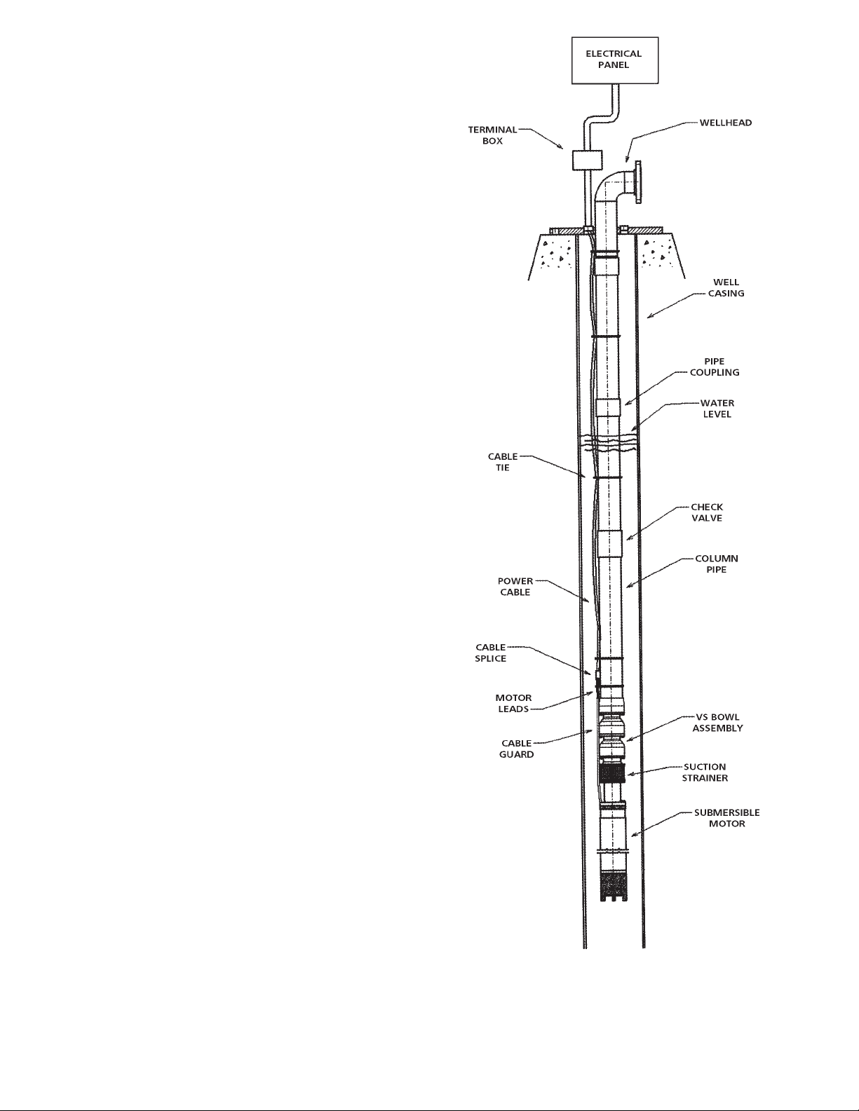
Goulds Water Technology model VS pump is a submersible turbine pump designed for maximum dependability.
See Figure 1 for typical VS pump.
3–2 DRIVERS
Goulds Water Technology furnishes only internationally
recognized motors designed for continuous operation
under any thrust which may develop throughout the
performance curve. Impeller adjustment and type of
coupling, splined or clamped, is dependent on the
specific motor being used.
3–3 DISCHARGE
The discharge bowl provides an NPT or BSP thread for
connecting to the well head or the first section of column
pipe.
Figure 1 – Typical Submersible Pump Installation
3–4 BOWL ASSEMBLY
The bowls are generally flanged construction for accurate
alignment and ease of assembly and disassembly. Impellers may be enclosed or open type. Impeller position is
set at factory. No field adjustment is required.
5
Page 6
CAUTION
CAUTION
CAUTION
WARNING
CAUTION
SECTION 4 — PREPARATION FOR
INSTALLATION
4–1 WELL REQUIREMENTS
1. The well should be developed with a test pump prior
to installing the submersible pump. Test pumping the
well serves several purposes. It removes the excess
sand encountered during the initial pumping of the
well. Pumping sand or other abrasives with a submersible pump will shorten the life of the pump and can
void the warranty.
DO NOT INSTALL THE UNIT WITH
THE MOTOR IN THE MUD, SAND
OR RESTING ON THE BOTTOM OF THE WELL.
IT IS IMPORTANT TO PREVENT THE WELL FROM
SANDING UP AT ANY TIME TO THE POINT THAT
THE MOTOR BECOMES EVEN PARTIALLY BURIED.
2. The test pumping also provides a means of determin-
ing the capacity and drawdown. The well capacity
should equal or exceed the pump capacity. If the pump
removes water at a higher rate than the well produces,
the drawdown will be excessive and the pump will
cavitate or 'starve' resulting in damage of the pump
and motor.
3. The well must be deep enough so that the pump suc-
tion is at least 10 feet below the expected drawdown
level. If the well screen or water producing aquifer is
above the pumping level, the required submergence of
the pump suction would be over 20 feet.
NEVER INSTALL UNIT WITH THE
BOTTOM OF THE MOTOR CLOSER
THAN FIVE FEET FROM THE BOTTOM OF THE
WELL.
4. The motor must always be immersed in flowing water.
The flow rate must be over .5 ft./sec. If the pump is set
below the well screen openings or other conditions exist that caused the water to be supplied from above the
pump, a flow induce sleeve should be used.
5. The inside diameter of the well casing must be large
enough to allow lowering the unit into the well without damage to the power cable, the splice between the
power cable and the motor leads. Many wells have
more than one size of casings installed and frequently
the lower sections are smaller in diameter than the
upper casing.
6. The submersible pump/motor unit must be operated
in a straight portion of the well. Exerted pressures can
and will cause misalignment of bearings or coupling.
When the straightness of the well is not known, it is
recommended to lower a test blank with the same
diameter and length as the pump/motor assembly with
electrical leads into the well to the desired depth. If
there is any doubt about straightness, gagging and
plotting are recommended.
4–2 PREPARING THE FOUNDATION
The foundation must be rigid, level and of adequate
strength to support the complete weight of the pump,
motor, column, plus the weight of the liquid passing
through it. It is recommended the foundation be constructed of solid concrete, however, adequate beams or
6
timbers may be used. A common foundation consists of
the following concrete mixture:
1. One part cement
2. Two parts sand
3. Four parts gravel
4. With sufficient water to make a stiff mix
4–3 MOTOR AND CABLE CHECKS AND
PREPARATION
DO NOT USE MOTOR LEADS TO
LIFT OR HANDLE THE MOTOR. THE
MOTOR LEADS ARE EASILY DAMAGED. THEY
SHOULD BE PROTECTED AND HANDLED WITH
CARE AT ALL TIMES.
1. MOTOR SERVICING
Consult the motor manual and perform any preinstallation servicing that is required. Some motors may
require filling with oil or water.
2. ASSEMBLE OF MOTOR TO PUMP
If the pump and motor have not already been assembled, assemble per the instructions given in Appendix
A. For extra long units, it may be more practical to assemble the pump to the motor in the vertical position
at the installation site.
3. TESTING BEFORE SPLICING POWER CABLE TO
MOTOR LEADS
Perform the following tests before making the splice
between the motor leads and the drop cable. Instructions for performing resistance tests and evaluating
the results are given in Appendix C.
MOTOR TESTS
• Measure the resistance between each motor lead
and ground with the motor submerged in water.
See Appendix C.
• Measure the resistance of the motor windings. See
Appendix C. Record the values for future reference.
• Secure the pump and motor with chain tongs to
resist torque. Energize the motor momentarily (on
and immediately off) to check the rotation.
GROUND THE UNIT WHEN TEST-
ING. FAILURE TO GROUND THE
UNIT PROPERLY CAN RESULT IN SERIOUS OR
FATAL SHOCK. ALSO, THE HIGH STARTING
TORQUE OF THE MOTOR WILL CAUSE IT TO
'KICK' WHEN POWER IS APPLIED. THE UNIT
SHOULD BE RESTRAINED SUFFICIENTLY TO PREVENT DAMAGE TO THE EQUIPMENT OR PERSONAL INJURY.
NOTE: ROTATION WILL BE COUNTERCLOCK-
WISE WHEN VIEWED FROM THE DISCHARGED BOWL.
On three phase unit, if rotation is wrong, interchange
any two of the motor leads at the control panel.
CORRECT ROTATION IS OF EX-
TREME IMPORTANCE. EXCESSIVE
OVERLOADS MAY BE DEVELOPED UNDER OPERATING CONDITIONS WITH REVERSE ROTATION.
Page 7
CAUTION
CAUTION
WARNING
DROP CABLE TEST
• Measure the resistance between the cable conductors and ground with the cable submerged in water.
See Appendix C.
4. SPLICING POWER CABLE TO MOTOR LEADS
A waterproof splice must be made to connect the
power cable to the motor leads. A properly made
splice will last the life of the pump. An improperly
made splice will become a service problem. Make the
splice per instructions supplied with the drop cable
or per instructions in the pump motor manual. The
splice should be located above the pump bowl. It
should be as compact as possible. A compact splice is
less likely to be damaged as the pump is being lowered
into the well. See Appendix B for instruction on splic-
ing the cable.
5. TESTING AFTER SPLICING POWER CABLE TO
MOTOR LEAD
Perform the following test after making the splice, but
before lowering the pump into the well.
• Check that the splice is waterproof by immersing it
in a container of water for approximately one hour
and then taking resistance readings between each
cable conductor and the water. See Appendix C.
• Measure the total resistance of the complete drop
cable and motor circuit to insure that a good splice
was made. Record the values for future reference.
THE MINIMUM READING FOR EACH
LEAD TO GROUND SHOULD BE 50
MEGOHMS.
SECTION 5 — INSTALLING THE PUMP
1. Check the pump and motor shaft to make sure it turns
free before installation. For some models, it may be
necessary to remove the suction screen in order to
check the shaft. Be sure to reinstall the suction screen.
2. Raise the bowl/motor assembly with the shipping skids
still in place. Remove the shipping skids and lower assembly into the well, clamping the bowl assembly near
the top.
3. Attach the elevators to the bottom column pipe imme-
diately below the column coupling. Hoist the column
section into place above the well and the top of the
bowl assembly, providing a soft board or pipe dolly
for the end of the column pipe to slide in on so that
threads will not be damaged while the section is being
raised. Clean all threads with thread lubricant. Thread
the pipe into the discharge bowl connection and make
up tight, using one set of chain tongs for backup.
THE PUMP MOTOR WILL EXERT
A TORQUE THAT WILL TEND TO
UNSCREW THREADED COLUMN PIPE CONNECTIONS. FOR THE REASON, THREADED COLUMN
JOINTS MUST BE TIGHTENED.
THE FOLLOWING TABLE GIVES THE NORMAL
AMOUNT OF THREAD ENGAGEMENT NECESSARY TO MAKE A TIGHT JOINT FOR THE NPT
THREAD JOINT:
Pipe Length of Number
Size Thread (in.) of Threads
3" 1" 8
4" 11/8" 9
5" 11/4" 10
6" 15/16" 101/2
8" 17/16" 111/2
10" 15/8" 13
4. Install a cable clamp on each side of the cable splice.
See Figure 1. Be careful not to damage the cable. If
an air line is to be installed, route it beside the cable,
making sure that it is not pinched by the clamps. If
there is any danger that the splice will rub against the
well casing during installation, it should be protected
by thick rubber chaffing pads or by a steel shield.
Check that the grounding system is in place.
FAILURE TO GROUND THE UNIT
PROPERLY CAN RESULT IN SERIOUS
OR FATAL SHOCK. REFER TO ELECTRICAL CODE
REQUIREMENTS.
5. Slowly lower the unit into the well (or sump) adding
joints of column pipe as the unit is lowered. Tighten
each joint securely. See note above. Remove slack from
the power cable and attach a cable clamp approximately every 20 feet. For units with large heavy power
cable, additional cable clamp may be required to give
additional support. Line up the cable on one side of
the pump and maintain as much clearance as possible
on that side when lowering the pump in the well. BE
EXTREMELY CAREFUL NOT TO SCRAPE OR
DAMAGE THE POWER CABLE, CABLE SPLICE
OR GROUNDING SYSTEM WHEN LOWERING
THE PUMP. Hold the power cable up away from the
well casing as lowering the pump into the casing.
6. If the pump does not have a built-in check valve, a line
check valve should be installed within 25 feet above
the pump bowl assembly. For a deep setting pump, a
line check valve is recommended for every 200 feet
of column pipe, However, no check valve should be
installed above the pumping level.
7. As soon as the splice joint is submerged in the water,
take a resistance reading between the power cable
conductors and ground to assure that the insulation
and the cable or the splice was not damaged during
installation.
8. After the last piece of column pipe has been installed,
install the well head. Install a cable clamp between the
last column pipe coupling and the well head base. See
Figure 1. Route the power cable and grounding system
through the large threaded hole in the head base.
Route the air line (if used) through one of the smaller
threaded holes in the head base. The remaining small
threaded hole is for connection of a well vent or other
accessories. All of these holes are threaded with standard NPT or BSP pipe threads. If a gasket is required
between the head base and its mounting surface, the
gasket should be placed on the foundation prior to
installing the well head.
7
Page 8
WARNING
CAUTION
9. After the well head has been properly tightened,
carefully rotate the entire unit in the well until the
discharge flange is facing in the desired direction. Push
the unit to one side of the well, providing the maximum clearance for the drop cable when rotating the
unit.
10. Slowly lower the well head onto its mounting
surface. BE CAREFUL NOT TO DAMAGE THE
GROUNDING SYSTEM OR PINCH THE POWER
CABLE BETWEEN THE SURFACE PLATE AND
THE WELL CASING. If a gasket or other seating
device is used, be sure that it is aligned properly and
that it is not damaged. Install the mounting bolts.
11. Before connecting the power cable to the control
panel:
Take a resistance reading between the power cable
conductors and ground to assure that the insulation
on the cable or splice was not damaged during installation. See Appendix C.
Measure the resistance of the power cable and motor
circuit. See Appendix C. Compare these readings with
those taken in Section 4 to assure that the splice is still
intact. Make the electrical connection between the power
cable and the control panel. It may be desirable to use a
terminal box at the well head to simplify the electrical
work required when the pump is pulled. Be sure that the
unit is grounded properly.
FAILURE TO GROUND THE UNIT
PROPERLY CAN RESULT IN SERIOUS
OR FATAL SHOCK. REFER TO ELECTRICAL CODE
REQUIREMENTS.
Be sure to connect the leads as they were marked
previously in the procedure.
SECTION 6 — STARTING THE PUMP
INITIAL STARTUP AND TESTING
MAY REQUIRE STARTING AND
STOPPING THE PUMP SEVERAL TIMES. BE SURE
TO ALLOW ADEQUATE COOLING OFF PERIOD
BETWEEN STARTS. CONSULT THE MOTOR MANUAL. IF NO INFORMATION IS GIVEN, A GOOD
RULE-OF-THUMB IS TO ALLOW A MINIMUM OF
15 MINUTES BETWEEN STARTS.
For initial startup, allow the water to be pumped out
onto the ground. A throttle valve in the discharge line is
recommended. Position the throttle valve approximately
one-forth open for startup of the pump. This will prevent
surging the well or the pump during startup.
If the pump has been in the well for several days before
the startup, check the resistance between the cable conductor and ground to assure that water has not penetrated the splice or the cable insulation. See Section 4.
Clamp the tongs of a clamp-on type ammeter around
one power lead to the pump. Set the ammeter on the
maximum scale. After the motor starts, it can be reset to
a lower scale as desired.
Refer to the motor manual and determine the normal
operating amps for the installed motor.
Start the pump and observe and record the current
readings on each conductor of the power lead. If the
8
current exceeds the normal value determined in the motor manual, stop the pump immediately. A high current
reading indicates that something is wrong. Among the
potential problems are:
• Incorrect pump rotation (3 phase only)
• Improper voltage
• Sand locked pump
• Improper cable size or leak in cable
• Mechanical damage
In any case, the problem must be corrected before the
pump can be operated.
On three phase units, if water does not appear within
one minute (deeper settings may require approximately
one half minute per 100 feet setting) the motor may be
running backwards. Stop the pump and interchange any
two of the three cable connections. If there is any doubt
about the proper rotation, run the motor in one direction
and then the other. The rotation that gives the highest
pressure and flow is always the correct one.
Check the voltage. The voltage when the pump is running should be within 5% of the pump motor nameplate
voltage.
Open the throttle valve. If a flow meter is available, open
the throttle valve to rated flow of the pump. If sand appears in the water, throttle the pump at approximately
80% of full flow until the sand clears. If excessive noise
develops, pressure fluctuates or water appears foamy
white, the pump is probably cavitating and the flow
should be throttled until the noise diminishes, the pressure remains steady and the water is clear.
On three phase units, check for current unbalance.
Details of the current unbalance test are given in the Appendix C. THE MAXIMUM ALLOWABLE CURRENT
UNBALANCE IS 5%. If the current unbalance exceeds
5% after rolling the leads and connecting them for the
lowest unbalance, the pump should be stopped and corrective action taken. Current unbalance in excess of 5%
can be expected to cause excessive heating in the motor
and premature failure. Operation with a current unbalance in excess of 5% will void the warranty.
After the unit is operating properly, a performance test
should be considered. If a performance test is conducted
when the pump is new, subsequent tests can be used to
determine the degree of wear or deterioration of the
pump without removing it from the well. After the unit
has been in operation for approximately one week, perform the routine tests.
SECTION 7 — PUMP DISASSEMBLY AND
REASSEMBLY
1. Clear a large area adjacent to the pump as storage
space for pump parts as they are disassembled. If the
pump has a long column, arrange parallel timbers on
the ground to support the pump column horizontally.
After disassembly for repair or replacement of pump
components, reassemble in all cases in the reverse
order of disassembly.
NOTE: PUMP COMPONENTS SHOULD BE
MATCH-MARKED PRIOR TO
DISASSEMBLY.
Page 9
2. It is recommended that maintenance personnel be-
WARNING
WARNING
come thoroughly familiar with the VS pump before
performing any removal of the components. Consult
the manufacturer's instructions for detailed disassembly information for the motor.
A. Remove the electrical connection at the conduit box
and tag electrical leads at the motor.
BEFORE OPENING THE CONDUIT
BOX OF AN ELECTRICAL MOTOR,
BE SURE THE CURRENT TO THE MOTOR IS SHUT
OFF. SEVERE INJURY TO PERSONNEL COULD
RESULT IF CONTACT WITH LIVE MOTOR LEADS
IS MADE.
LOCK OUT SHOULD BE INSTALLED BEFORE ANY
ELECTRICAL WORK IS PERFORMED.
NOTE: MATCH-MARK PARTS IN SEQUENCE OF
DISASSEMBLY TO AID IN THE REASSEMBLY PROCEDURE.
B. Disconnect the discharge piping from the well head.
DO NOT WORK UNDER A HEAVY
SUSPENDED OBJECT UNLESS THERE
IS A POSITIVE SUPPORT UNDER IT WHICH WILL
PROTECT PERSONNEL SHOULD A HOIST OR
SLING FAIL.
3. PUMP DISASSEMBLY
In the following pump disassembly procedures, references are made to installation sections of this manual.
These sections will aid in the disassembly of the
pump.
A. Disconnect well head and begin removal of column
sections. Refer to Section 5, #7.
B. For removal of bowl/motor assembly, hoist the
bowl/motor assembly from the well, using elevator clamps. Hoist in the same manner as for the
column. For the keyed motor shaft, loosen the
setscrews on the motor end of the shaft coupling.
Remove the motor lead from the cable guard.
Disassemble the bowl assembly from the motor by
removing the connecting bolts at the flange joint.
For the short assembly, laying the bowl/motor assembly on the ground to perform these works. For
the long or large size assembly, it is recommended
to perform these works while the assembly is in the
vertical position. Refer to Section 4, #3. Proceed to
disassemble the bowl assembly as follows.
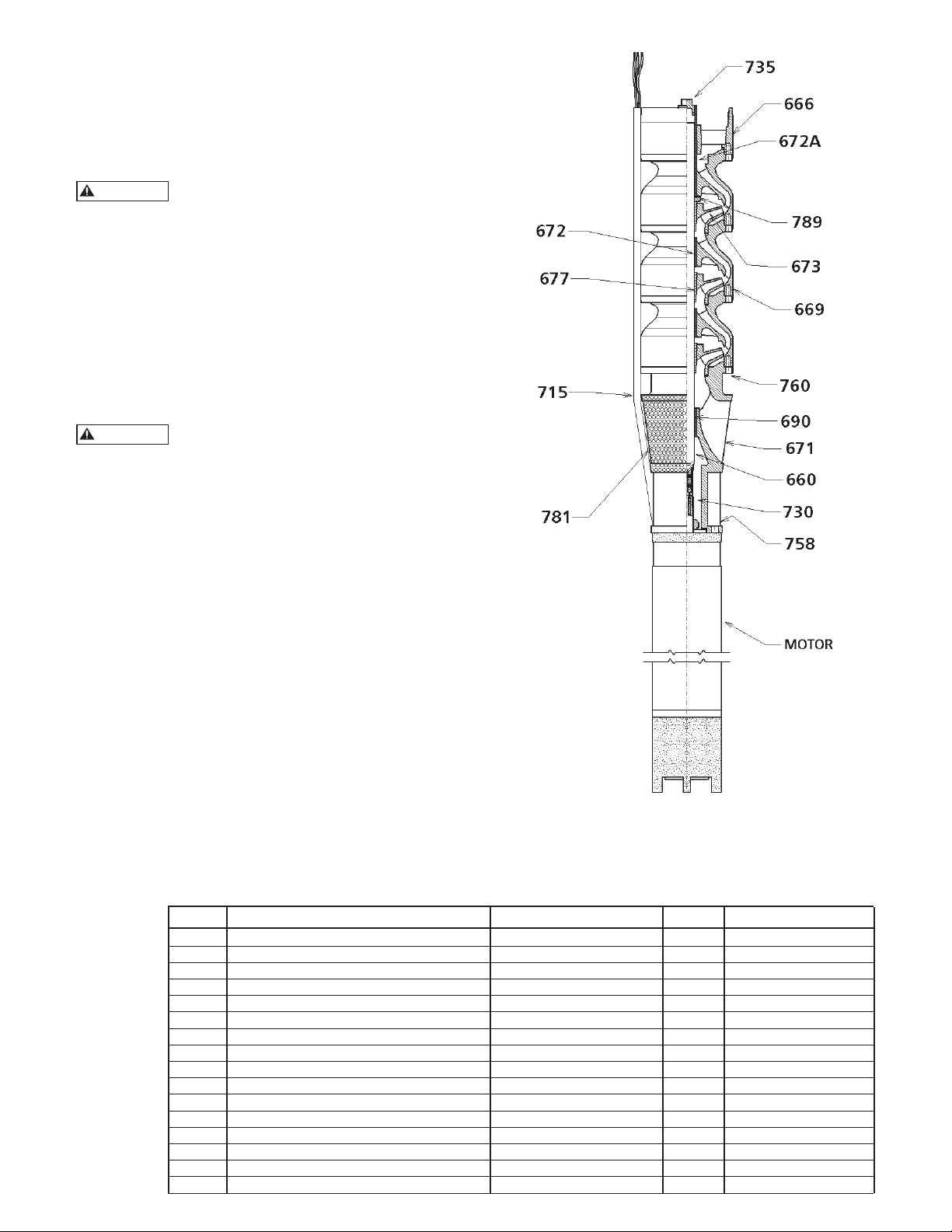
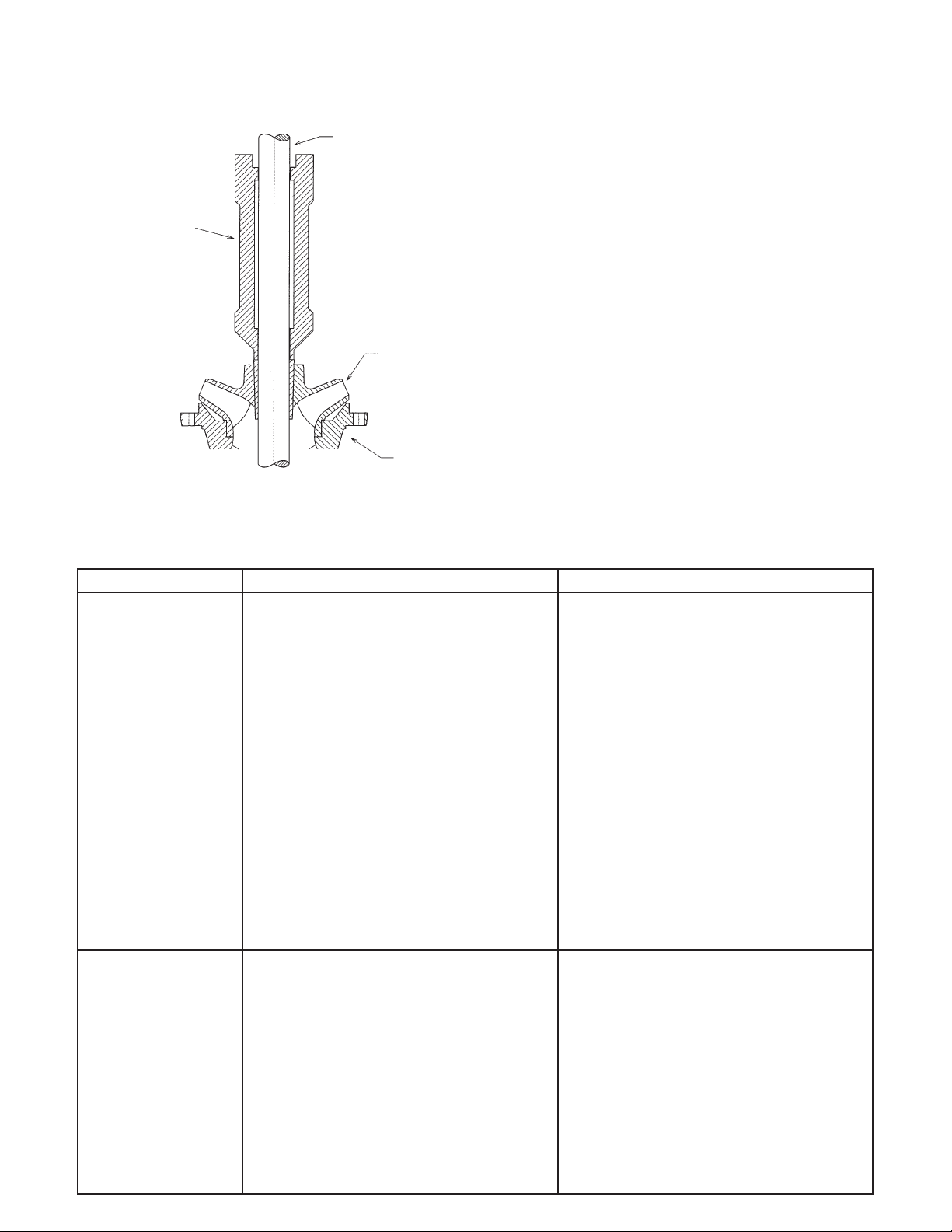
Figure 2 – Bowl and Motor Assembly
ITEM NAME MATERIAL GPI ASTM
666 Bowl Discharge Iron 1003 A48 CL30
669 Bowl - Intermediate Cast Iron - Glassed 6911 A48 CL30
672 Bearing - Intermediate Bowl Bronze 1109 B584 C90300
672A Bearing Discharge Bronze 1109 B584 C90300
690 Bearing Subadapter Bronze 1109 B584 C90300
760 Capscrews - Grade 8 Steel 2298 SAE J429 GR8
758 Capscrews SST 304 2228 A276 S30400
730 Coupling Motor SST 416 2218 A582 S41600
715 Guard Cable SST 304 3215 A240 S30400
673 Impeller Bronze 1102 B584 C87600
781 Screen Suction SST 304 3215 A240 S30400
660 Shaft SST 416 2227 A582 S41600
671 Subadapter Duct Iron 1018 A536 65-45-12
677 Taperlock Steel 2242 A108 G10180
789 Washer Upthrust HDPE 6266 Polyethylene
735 Pipe Plug Iron 1046 A197
9
Page 10
4. BOWL DISASSEMBLY
The bowl assembly shown in Figure 2 is composed of
a discharge bowl (for the model with built-in check
valve, it would be column adapter), intermediate
bowl, impellers with taper collects, motor adapter,
bearings and pump shaft.
A. Begin disassembly by removing the capscrews that
secure the top stage intermediate bowl and the second stage intermediate bowl and slide the discharge
and top intermediate bowls off the pump shaft
together. Remove the thrust washer.
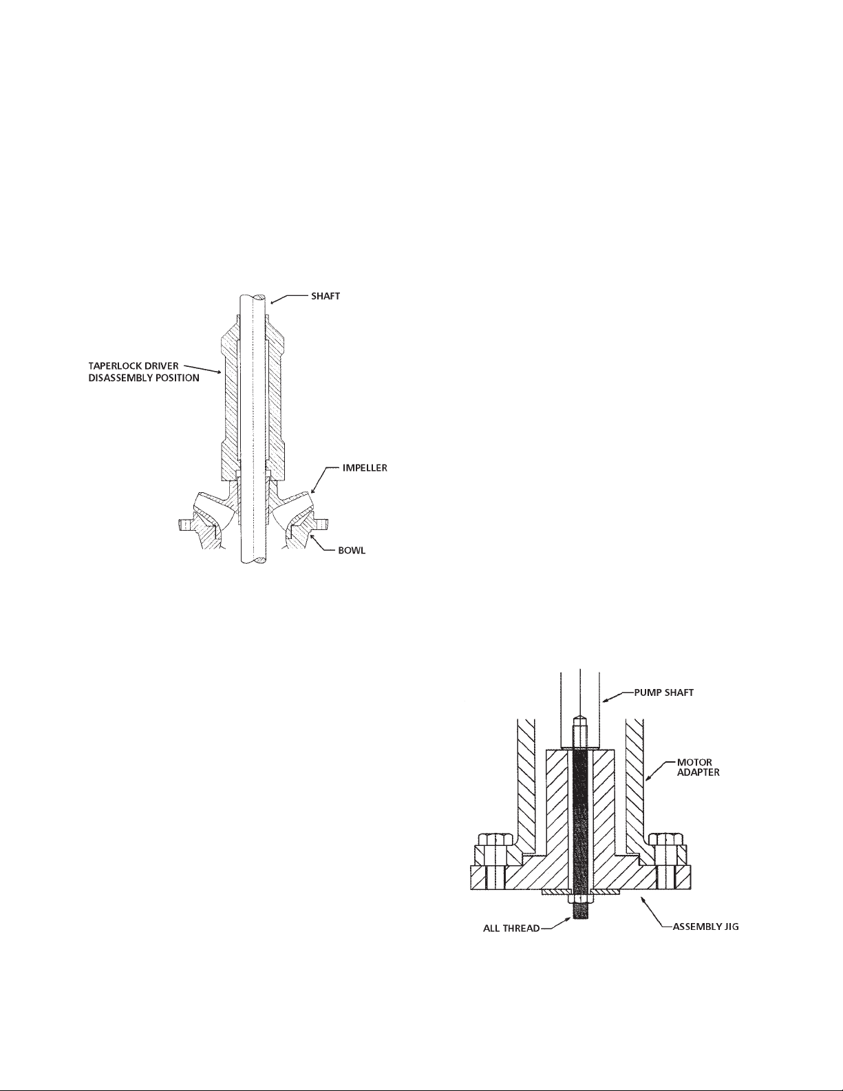
B. Pull shaft out as far as possible and strike impeller
hub utilizing a taperlock driver or equivalent sliding
along the pump shaft to drive the impeller off the
taperlock. See Figure 3.
Figure 3 – Disassemble the Impeller
C. After impeller is freed, insert a screwdriver into the
taperlock to spread it. Slide taperlock and impeller
off the pump shaft.
D. Use the preceding procedures until entire turbine
bowl assembly is completely disassembled.
5. TURBINE BOWL – WEAR RINGS REMOVAL
(OPTIONAL)
A. Utilizing a diamond point chisel, cut two V-shape
grooves on the bowl wear ring, approximately 180º
apart. Use extreme care not to damage the wear
ring seat.
B. With a chisel or equal, knock the end of half of the
ring in and pry the ring out.
C. On special materials such as chrome steel, set up the
bowl in a lathe and machine the wear ring off. Use
extreme care not to machine or damage the ring
seat.
6. TURBINE BOWL – IMPELLER WEAR RING
REMOVAL (OPTIONAL)
Set up impeller in a lathe and machine wear ring out.
Use extreme care not to machine or damage ring seat
or impeller hub. Impeller wear ring may also be removed by following steps A and B, paragraph #5.
7. BOWL BEARING REMOVAL
Utilizing an arbor press and a piece of pipe or sleeve
with outside diameter slightly smaller than the bowl
bearing diameter, press the bearing out.
8. INSPECTION AND REPLACEMENT
A. Clean all parts thoroughly with a suitable cleaner.
B. Check bearing seats for deformation and wear.
C. Check pump shaft for straightness and excessive
wear on bearing surfaces. Check straightness of the
pump shaft. The straightness should within 0.0005"/
ft. TIR.
D. Visually check impellers and bowls for cracks and
pitting. Check all bowl bearings for excessive wear
and corrosion.
9. TURBINE BOWL AND IMPELLER WEAR RING
INSTALLATION (OPTIONAL)
Place chamfered face of bowl or impeller wear ring
towards the ring seat and press. Use an arbor press or
equal. Make sure ring is flush with edge of wear ring
seat.
10. BOWL BEARING INSTALLATION
Press the bearing into all the bowls by using an arbor
press or equivalent. Press the bearing in from the
bottom end of the hub until the bottom end of the
bearing is flush with the bottom end of the hub.
11. TURBINE BOWL WITH TAPERLOCK –
REASSEMBLY
A. Secure the submersible assembly jig to the motor
end of the motor adapter. See Figure 4. Be sure
to use the proper jig for the motor frame size the
bowl assembly is intended to adapt to.
B. Put some grease in the suction bearing of the
motor adapter. Slide the shaft through the bearing. Secure the shaft in place by locking the shaft
to the assembly jig with a special long bolt or all
thread and a hex nut. See Figure 4.
Figure 4 – Assembly Jig
C. Slip impeller over the shaft. Then slip taperlock
over the shaft with smaller end towards impeller.
A screwdriver can be used to spread the taperlock
for ease in slipping over the shaft.
10
Page 11
D. Hold impeller firmly against the motor adapter
and drive the taperlock into place with the taperlock driver. See Figure 5. After the impeller is
secured in position, the top end of the taperlock
should be 1/8" above the impeller hub.
SHAFT
TAPERLOCK
DRIVER
ASSEMBLY
POSITION
IMPELLER
BOWL
Figure 5 – Install the Impeller
E. Put a little grease on the shaft where the inter-
mediate bearing will be. Slip intermediate bowl
over the shaft and bolt or screw it onto the motor
adapter.
F. Place the next impeller over the shaft and continue
to assemble as explained above.
G. After assembling the last impeller, slide the up-
thrust washer over the shaft before assembling the
top intermediate.
H. Slide the discharge case and top intermediate
bowl over the shaft and bolt it to the second intermediate bowl. If the pump has a built-in check
valve, install the check valve before installing the
discharge adapter.
I. When the bowl is completely assembled, unlock
the shaft and remove the assembly jig. Rotate the
shaft by hand to see whether it rotates freely. Push
the shaft all the way in and then pull it all the
way out to check the lateral clearance. The lateral
should be between 0.187" to 0.250".
J. Install the square key in the keyway at the motor
end of the pump shaft. Slide the shaft coupling
over the shaft and secure it to the key with two
setscrews.
SECTION 8 — TROUBLESHOOTING CHART
In case of difficulties, refer to the chart to locate basic problems with the system. Once the problem is located, refer to
specific sections in this manual for details.
CONDITION PROBABLE CAUSE REMEDY
PUMP WILL 1. Motor overload protector trip 1. Allow motor to cool, overload will
NOT RUN a. Incorrect control box. automatically reset. Investigate cause
b. Incorrect connections. of overload.
c. Faulty overload protector. a-e. Have a qualified electrician inspect
d. Low voltage. and repair, as required.
e. Ambient temperature of control box
or starter too low. f. Pull the pump, examine and clean.
f. Pump bound by foreign matter. Adjust set depth as required.
2. Blown fuse, broken or loose electric 2. Check fuses, relays or heater elements
connections. for correct size capacitor and all electrical
connections.
3. Motor control box or starter not in 3. Make sure box is in upright position.
proper position.
4. Cable insulation damaged. 4. Locate and repair as per instructions.
5. Splice may be open or grounded. 5. Check resistance between cable leads
with ohmmeter. If open or grounded,
pull pump and resplice.
6. Faulty pressure switch. 6. Repair or replace.
7. Faulty liquid level control. 7. Check relay, wires and electrodes.
PUMP RUNS 1. Line check valve backward. 1. Reverse check valve.
BUT NO WATER 2. Pump is air-bound. 2. Successively start and stop pump until
water flows normally.
3. Lift too high for the pump. 3. Review performance requirement.
4. Suction screen or impeller plugged, 4. Pull the pump and clean, check well
or pump in mud or sand. depth. Raise setting if necessary.
5. Pump not submerged. 5. Check water level. Lower pump if
permissible.
6. Well may contain excessive amounts 6. Start and stop pump several times. If this
of air or gas. does not remedy conditions, pump may
not be able to cooperate because of too
much gas in the well.
7. Three-phase unit running backwards. 7. Reverse rotation.
11
Page 12

SECTION 8 — TROUBLESHOOTING CHART (continued)
CONDITION PROBABLE CAUSE REMEDY
REDUCED 1. Lift too high for the pump. 1. Check rating.
CAPACITY OR 2. Screen or impellers partly plugged. 2. Pull pump and clean.
INSUFFICIENT 3. Scaled or corroded discharge pipe or 3. Replace pipe and repair leaks.
TANK PRESSURE leaks anywhere in system.
4. Well may contain excessive amounts of 4. Start and stop pump several times. If this
air or gas. does not remedy conditions, pump may
not be able to cooperate because of too
much gas in the well.
5. Excess wear due to abrasives. 5. Replace worn parts.
6. Three-phase pump running backward. 6. Reverse rotation.
PRESSURE 1. Incorrect set. 1. Change settings.
SWITCH 2. Switch opening plugged. 2. Pull pump and clean.
DOES NOT 3. Leaks anywhere in system. 3. Repair leaks.
CUT OUT 4. Three-phase pump running backward. 4. Reverse rotation.
PUMP STARTS 1. Water-logged tank. 1. a. Check tank for leaks (plug at top of
TOO FREQUENTLY tank may be leaking air).
b. Be sure drain and 'Y' fittings are
functioning properly. Check operation
of snifter valve.
2. Check valve leaking. 2. Replace check valve.
3. Pressure switch out of adjustment. 3. Readjust to correct setting or replace.
4. Leaks in service line. 4. Locate and correct.
APPENDIX A — ASSEMBLY OF PUMP AND
MOTOR
Most of the time, the pump and the motor are shipped
separately in two different boxes. They need to be assembled together in the field prior to being installed in
the well. For the short pump (less than 5 stages), the motor and pump may be assembled together on the ground
horizontally. If the pump is over 6 stages long, it is recommended to assemble them in the vertical position.
1. Check that the pump shaft and the motor shaft turn
freely.
2. Clean the flange faces and the registers on the pump
and the motor. Remove all burrs from these areas.
Clean the exposed portion of the pump shaft and
motor shaft. If the pump is supplied with the coupling
assembled on the shaft, clean the inside of the motorend of the coupling.
3. Install the key on the motor shaft, if it is not the
splined shaft.
4. If the shaft coupling has setscrews in the motor half of
the coupling, loosen or remove these setscrews.
5. Align the motor with the pump and slide the motor shaft into the shaft coupling on the pump until
the shaft butts. Make sure the motor shaft lifts the
pump shaft by 1/8" to ¼" (for enclosed impeller only).
Be careful not to damage the shaft, the coupling or
the key. Orient the motor so that the motor leads
are aligned with the notch provided in the pump's
mounting flange. If the shaft coupling has setscrews
in the motor half the coupling, install and tighten the
setscrews.
6. Install and tighten the mounting bolts (or capscrews)
on the flange.
12
7. Unite the cableguard on the pump and reassemble it
with the motor leads under the cableguard to prevent
damaging the leads, when lowering the pump into the
well.
APPENDIX B — SPLICING POWER CABLE
TO MOTOR LEADS
A waterproof splice must be made to connect the power
cable to the motor leads. A properly made splice will
last the life of the pump. An improperly made splice will
become a service problem. In the market, there are different materials and methods to make waterproof cable
splices. For example: by waterproof tapes, by resin castings, by heat shrink tubes.
TAPED CABLE SPLICE:
1. Strip the insulation of each conductor of the power cable back enough to allow the conductor to extend half
way through a sleeve type connector. Crimp connector to the conductor. Strip the insulation of the motor
lead same as the power cable. Fit it into the connector
and butt against cable end. Crimp connector as before.
Pull on wire to make sure connector is firmly crimped
to both the motor lead and the power cable. Scrape
the insulation to move any loose bits of tape or thread
and roughen surface. Thoroughly clean surface with
solvent. This will insure a watertight splice.
2. Tape individual joints with rubber electrical tape. Start
at the center of the connector and tape 2" past the end
of conductor insulation end. Stretching tape about
10% while taping, overlap tapes about one half of
tape width. Make two layers. The end of second layer
should be 2" beyond the end of the first layer.
3. Tape over the rubber electrical tape with #33 Scotch
electrical tape or equivalent, using two layers as in
step #2 and making each layer overlap the end of the
preceding layer by 2".
Page 13
CAST CABLE SPLICE:
DANGER
DANGER
1. To prepare the 3-conductor power cable for splicing,
insert a sharp knife blade between the cable jacket and
lead insulation and strip the jacket back 21/2" from the
end. Taking care not to cut the lead insulation. Strip
the cambric wrapping (if any) off the conductors and
strip back rubber insulation 5/8" from the end. Assemble the cable connectors and crimp them in place using
a crimping tool.
2. Cut off the motor leads to equal length. Clean off the
ends of the leads for about a foot, using a cloth wet
with gasoline or solvent. Clean the end of the power
cable also. Insert the three motor leads into the corresponding holes in the bottom of the rubber casing
and push them several inches out the top. Crimp the
motor leads into the corresponding connectors, crimping the center one first. Bend the cables into line with
the holes in the casing and slip the casing up until the
connectors are inside the holes and about 1/4" from the
top.
3. Mix the resin as directed. Cut off a corner of the bag
and squeeze all of the resin into casing. With the roll
of tape on hand, fold the bag and tape the top of the
bag snuggly to the power cable until the resin runs
out over the top. This will assure maximum coverage
of the resin and minimum size of the finished splice.
When the resin is firm to touch, the splice may be immersed for testing.
APPENDIX C — ELECTRICAL TESTS
1. MEASURING INSULATION RESISTANCE
(GROUND TEST)
The condition of the insulation around a conductor
can be determined by measuring the electrical resistance between the conductor and ground. This measurement can be made with a megger or an ohmmeter.
The value is stated in ohms or megohms (ohms x
1,000,000). High ohm values indicate good insulation.
The basic procedure for measuring insulation resistance is given below:
A. Turn off all power and disconnect the leads to be
tested from the electrical panel. Lock out the panel.
FAILURE TO TURN OFF THE POWER
WILL DAMAGE THE METER AND
CAN CAUSE SERIOUS OR FATAL SHOCK.
Failure to disconnect the leads can result in false
readings.
B. Set the meter selector knob to RX 100K or RX
100,000 (some meters may not have RX 100K
in which case EX 10K or EX 10,000 scale can be
used). Clip the meter leads together and adjust the
meter to zero.
C. Unclip the leads and attach one of the meter leads
to one of the power cable leads or motor leads. The
other meter to the ground.
D. Do not touch any bare wires or allow bare wires
to come in contact with the ground or metal. False
readings will result.
E. If the meter needle is at either extreme end of the
scale, a more accurate reading can be obtained
by switching the selector switch to another scale.
Rezero the meter each time the selector switch is
moved.
The readings obtained from power cables and motor leads should be within the range specified in Table
C.1. Low readings indicate that the motor windings are
grounded or that the cable or splice insulation is damaged. If low or marginal readings are obtained on a new
installation the problem should be corrected before
proceeding with the installation.
2. MEASURING RESISTANCE BETWEEN LEADS
(MOTOR WINDING RESISTANCE)
The general conditions of motor windings can be
determined by measuring the resistance of the motor
windings (i.e. the resistance between the motor leads)
and comparing the measured resistance with values
given in the motor manual. The resistance is measured
with an ohmmeter and the value is stated in ohms.
The basic procedure for measuring motor winding
resistance is given below:
A. Turn off the power and disconnect the leads to be
tested from the panel. Lock out the panel.
FAILURE TO TURN OFF THE POWER
WILL DAMAGE THE METER AND
CAN CAUSE SERIOUS OR FATAL ELECTRICAL
SHOCK.
Failure to disconnect the leads can result in false
readings.
B. Set the meter selector knob to 'RX 1'. Clip the me-
ter leads together and adjust the meter to zero.
C. Unclip the meter leads and attach them to the
motor leads.
Resistance measured between the motor leads prior to
splicing the power cable to the motor leads should be
within the motor winding resistance limits specified in
the motor manual.
13
Page 14

TABLE C.1 — NORMAL INSULATION RESISTANCE VALUES BETWEEN ALL LEGS AND
GROUND
Insulation resistance does not vary with rating. Motors of all HP, voltage and phase rating have the same insulation
resistance ranges.
METER READING
R x 100,000 R x 10,000
Scale Scale
BENCH TESTS
• A new motor (without drop cable). 20,000,000+ 20+ 200+ 2000+ or 2K+
• A used motor which can be reinstalled 10,000,000+ 10+ 100+ 1000+ or 1K+
• Cable splice after immersion for one 2,000,000+ 2+ 20+ 200+
WELL TESTS Ohm readings are for drop
cable plus motor.
• A new motor or used motor in good 2,000,000+ 2+ 20+ 200+
condition.
• A motor in reasonably good condition. 500,000– 0.5–2.0 5–20 50–200
2,000,000
• A motor which may have been damaged 20,000– 0.02–0.5 0.2–5 2–50
by lightning or with damaged leads. 500,000
Do not pull the pump for this reason.
• A motor which denitely has been 10,000– 0.01–0.02 0.1–0.2 1–2
damaged or with damaged cable. The 20,000
pump should be pulled and repairs
made to the cable or the motor replaced.
The motor will not fail for this reason
alone, but will probably not operate for
long.
• A motor which has failed or with Less than 0–0.01 0–0.1 0–1
completely destroyed cable insulation. 10,000
The pump must be pulled and the
cable repaired or the motor replaced.
+ Indicates that the reading should be the value shown or greater. Higher readings indicate better insulation.
CONDITION OF MOTORS
AND LEADS
in the well.
hour in water.
OHMS MEGOHMS or or
R x 100K R x 10K
Resistance measured between the power cable leads after
splicing the power cable to the motor leads will indicate
the resistance of the power cable plus the motor windings. The motor winding resistance is obtained by the
formula below. The calculated value should be within the
limits specified in the motor manual.
Motor Winding = Reading taken – Cable Resistance
Resistance at Power Cable from Table 2.
14
A higher winding resistance than shown in the motor
manual indicates a possible burned (open) winding, an
open cable, a loose connection or the wrong motor (different HP or voltage than readings being referenced).
A considerably lower winding resistance than shown in
the motor manual indicates a possible shorted (burned
together) winding or the wrong motor.
Unequal resistance between the windings on a three
phase motor indicates a burned winding or a faulty connection.
Page 15
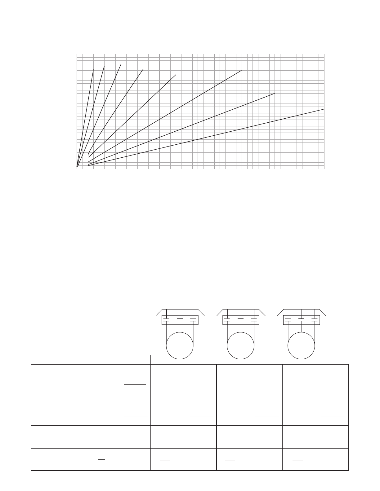
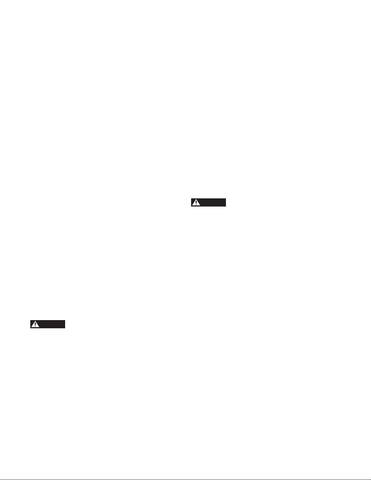
TABLE C.2 — POWER CABLE RESISTANCE
Pump Setting (feet)
1ST HOOK UP
2ND HOOK UP
3RD HOOK UP
The values below are for copper conductors. If aluminum conductor drop cable is used, the resistance will be higher
for each foot of cable of the same size. To determine the actual resistance of aluminum drop cable, divide the ohm
readings from this chart by 0.61. This chart shows total resistance of cable from control box to motor and back.
1750
1500
1250
1000
750
500
250
#0
#2
#4
#6
#8 Cable
#10 Cable
#12 Cable
#14 Cable
0
0 0.5
1
1.5 2 2.5 3 3.5 4 4.5
Power Cable Ohms
3. CURRENT UNBALANCE TEST:
A. For three phase units, after correct rotation has
been established, check the current in each of the
three motor leads and calculate the current unbalance as explained below. If the current unbalance is
2% or less, leave the leads as connected. If the current unbalance is over 2%, current readings should
be checked on each leg using one of three possible
hook-ups indicated in the table below. Roll the
motor leads across the starter in the same direction
to prevent motor rotation reversal. This procedure
is commonly known as "rolling the leads". THE
HOOKUP THAT RESULTS IN THE LOWEST
PERCENT CURRENT UNBALANCE SHOULD
BE USED FOR THE FINAL CONNECTION OF
THE POWER LEADS.
B. Current unbalance is determined by measuring
the amperage of each of the three legs and then
calculating the percent current unbalance using the
formula below. This calculation must be performed
using each of the three hookups shown.
Maximum Current difference in
Percent Current Unbalance = any leg from average current x 100
Average Current
L1 L2 L3
T2
T1 T3
L1 L2 L3
T1
T3 T2
L1 L2 L3
T3
T2 T1
SUPPLY
STARTER
MOTOR
Sample Calculation
• Measure current in T1 L1 51 amps T1 L1
each leg. T2 L2 46 amps T2 L2
T3 L3 53 amps T3 L3
• Add leg currents to 150 amps
determine total
current.
• Calculate average
leg current. 50 amps
• Determine maximum 51 – 50 = 1
difference of any one 50 – 46 = 4 max
leg from the average. 53 – 50 = 3
• Calculate percent
unbalance using
formula above.
4
x 100 = 8%
50
____________
____________
____________
T3 L1
T1 L2
T2 L3
_____________
_____________
_____________
T2 L1
T3 L2
T1 L3
_____________
_____________
_____________
÷ 3 ÷ 3 ÷ 3 ÷ 3
_____– _____= _____ _____– _____= ____ _____– _____= _____
_____– _____= _____ _____– _____= ____ _____– _____= _____
➛
_____– _____= _____ _____– _____= ____ _____– _____= _____
x 100 = %
x 100 = %
x 100 = %
15
Page 16

C. THE CURRENT UNBALANCE BETWEEN LEGS
SHOULD NOT EXCEED 5% at service factor load or
10% at rated input load. If the unbalance cannot be
corrected by rolling leads, the source of the unbalance
must be located and correct.
D. By observing where the furthest current reading from
the average is for each leg of each of the hookups, the
cause of the unbalance can be determined. If the leg
furthest from average is always on the same motor
lead, the primary source of unbalance is on the "motor
side" of the starter. In this instance, consider a damaged cable, leaking splices, poor connection or faulty
motor winding.
LIMITED WARRANTY
Company warrants title to the product(s) and, except as noted with respect to items not of Company’s manufacturer, also warrants
the product(s) on date of shipment to Purchaser, to be of the kind and quality described herein, and free of defects in workmanship
and material. THIS WARRANTY IS EXPRESSLY IN LIEU OF ALL OTHER WARRANTIES, INCLUDING BUT NOT LIMITED TO
IMPLIED WARRANTIES OF MERCHANTABILITY AND FITNESS, AND CONSTITUTES THE ONLY WARRANTY OF COMPANY
WITH RESPECT TO THE PRODUCT(S).
If within one year from date of initial operation, but not more than 18 months from date of shipment by Company of any item of
product(s), Purchaser discovers that such item was not as warranted above and promptly notifies Company in writing thereof, Company
shall remedy such nonconformance by, at Company’s option, adjustment or repair or replacement of the item and any affected part
of the product(s). Purchaser shall assume all responsibility and expense for removal, reinstallation, and freight in connection with the
foregoing remedies. The same obligations and conditions shall extend to replacement parts furnished by Company hereunder. Company
shall have the right of disposal of parts replaced by it. Purchaser agrees to notify Company, in writing, of any apparent defects in design,
material or workmanship, prior to performing any corrective action back-chargeable to the Company. Purchaser shall provide a detailed
estimate for approval by the Company.
ANY SEPARATE LISTED ITEM OF THE PRODUCT(S) WHICH IS NOT MANUFACTURED BY THE COMPANY IS NOT
WARRANTED BY COMPANY and shall be covered only by the express warranty, if any, of the manufacturer thereof.
THIS STATES THE PURCHASER’S EXCLUSIVE REMEDY AGAINST THE COMPANY AND ITS SUPPLIERS RELATING TO THE
PRODUCT(S), WHETHER IN CONTRACT OR IN TORT OR UNDER ANY OTHER LEGAL THEORY, AND WHETHER ARISING
OUT OF WARRANTIES, REPRESENTATIONS, INSTRUCTIONS, INSTALLATIONS OR DEFECTS FROM ANY CAUSE. Company
and its suppliers shall have no obligation as to any products which have been improperly stored or handled, or which have not been
operated or maintained according to instructions in Company or supplier furnished manuals.
LIMITATION OF LIABILITY – Neither Company nor its suppliers shall be liable, whether in contract or in tort or under any other
legal theory, for loss of use, revenue or profit, or cost of capital or of consequential damages, or for any other loss or cost of similar type
or for claims by Purchaser for damages of Purchaser’s customers. Likewise, Company shall not under any circumstances be liable for the
fault, negligence, wrongful acts of Purchaser or Purchaser’s employees, or Purchaser other contractors or suppliers.
IN NO EVENT SHALL COMPANY BE LIABLE IN EXCESS OF THE SALES PRICE OF THE PART OR PRODUCT FOUND
DEFECTIVE.
Xylem Inc.
PO Box 5487
Lubbock, TX 79408
Phone: 1-806-763-7867
Fax: 1-800-453-4749
www.gouldswatertechnology.com
Goulds is a registered trademark of Goulds Pumps, Inc. and is used under license.
© 2012 Xylem Inc. IMVSR01 December 2012
Page 17

MANUAL DE INSTRUCCIÓN
IMVSR01
MODELO VS
BOMBAS INDUSTRIALES VERTICALES DE LA TURBINA
INSTRUCCIONES DE INSTALACIÓN, OPERACIÓN Y MANTENIMIENTO
Page 18

Prefacio
Prefacio
Este manual proporciona instrucciones para la instalación, la operación y el mantenimiento de las bombas
de turbina de pozo profundo Goulds Water Technology en su versión estándar. Para las opciones especiales
existen instrucciones complementarias. Este manual debe leerse y entenderse antes de instalar y arrancar la
bomba.
Este manual cubre diferentes modelos de bombas ya que la mayoría de los procedimientos de ensamble,
desensamble e inspección es igual para todas ellas, y donde hay diferencias se indican. Gracias al diseño,
materiales y mano de obra que se usan en su fabricación, las bombas DWT de Goulds Water Technology
pueden operar de manera continua sin presentar problemas. No obstante, la vida útil de cualquier dispositivo
mecánico se extiende y su operación mejora si se usa y se instala de manera correcta, se inspecciona
periódicamente, se monitorea sus condiciones y se le da el mantenimiento adecuado. El propósito de este
manual es ayudarles a los operadores a entender la construcción de estas bombas e indicarles los métodos
correctos de su instalación, operación y mantenimiento.
La información que contiene este instructivo pretende proporcionarle al personal de operación las
características del equipo adquirido. No libera al usuario de su responsabilidad de usar prácticas de ingeniería
aceptadas en la instalación, operación y mantenimiento de este equipo.
Goulds Water Technology no se hace responsable de lesiones físicas, daños o retrasos causados por no
observar las instrucciones de instalación, operación y mantenimiento que contiene este manual.
La garantía es válida solo cuando se usan partes de repuesto genuinas de Goulds Water Technology.
Usar el equipo en una aplicación no establecida en el pedido deja sin validez a la garantía, a menos que se haya
obtenido con anticipación una aprobación por escrito de Goulds Water Technology.
Si requiere información o tiene preguntas no tratadas en este manual, llame a Goulds Water Technology al (806)
743-5700.
ESTE MANUAL EXPLICA :
• la instalación correcta; • la revisión global de la bomba;
• el procedimientos de arranque; • la investigación y solución de fallas;
• los procedimientos de operación; • cómo pedir partes de repuesto.
• el mantenimiento de rutina;
Información del propietario
Número de modelo de la bomba:
Número de serie de la bomba:
Número de control de modelo:
Distribuidor:
No. de teléfono del distribuidor:
Fecha de compra: Instalación:
Lecturas de corriente durante el arranque:
1 Ø 3 Ø L1-2 L2-3 L3-1
Amps: Amps:
Voltios: Voltios:
18
Page 19

Tabla de contenido
CAPITULO PÁGINA
Instrucciones de seguridad ...........................................................................................................................................20
Sección 1 — Información general
Introducción ...........................................................................................................................................................20
Recepción y revisión ...............................................................................................................................................20
Materiales y equipo que se requieren ......................................................................................................................20
Sección 2 — Almacenaje
Almacenaje ..............................................................................................................................................................20
Preparación para el almacenaje ................................................................................................................................21
Procedimientos recomendados para el almacenaje ...................................................................................................21
Preparación para un almacenaje no controlado de largo plazo .................................................................................21
Sección 3 — Descripción general
Descripción general .................................................................................................................................................21
Accionamientos .......................................................................................................................................................21
Descarga .................................................................................................................................................................22
Ensamble de los tazones ..........................................................................................................................................22
Sección 4 — Preparación para la instalación
Requisitos para el pozo ...........................................................................................................................................22
Preparación de la cimentación .................................................................................................................................22
Verificación y preparación de los cables y del motor ................................................................................................22
Sección 5 — Instalación de la bomba ...........................................................................................................................23
Sección 6 — Arranque de la bomba .............................................................................................................................24
Sección 7 — Desensamble y reensamble de la bomba
Desensamble de la bomba .......................................................................................................................................25
Desensamble de los tazones .....................................................................................................................................26
Tazón de la turbina – remoción del anillo de desgaste (opcional) .............................................................................26
Tazón de la turbina – remoción del anillo de desgaste del impulsor (opcional) ........................................................26
Remoción del cojinete del tazón ..............................................................................................................................26
Inspección y reemplazo ...........................................................................................................................................26
Instalación del anillo de desgaste del tazón de la turbina y del impulsor (opcional)..................................................26
Instalación del cojinete del tazón .............................................................................................................................27
Tazón de la turbina con casquillo – reensamble .......................................................................................................27
Sección 8 — Gráfica de investigación y solución de fallas ............................................................................................28
Apéndice A — Ensamble de la bomba y del motor ......................................................................................................29
Apéndice B — Empalme del cable de potencia con los conductores del motor .............................................................29
Apéndice C — Pruebas eléctricas .................................................................................................................................30
Garantía limitada .........................................................................................................................................................34
19
Page 20

INSTRUCCIONES DE SEGURIDAD
ADVERTENCIA
PRECAUCIÓN
PELIGRO
ADVERTENCIA
PRECAUCIÓN
AVISO: INDICA INSTRUCCIONES ESPECIALES
SECCIÓN 1 — INFORMACIÓN GENERAL
1–1 INTRODUCCIÓN
Gracias al diseño, materiales y mano de obra que se usan
en su fabricación, las bombas DWT de Goulds Water
Technology pueden operar de manera continua sin presentar problemas. No obstante, la vida útil de cualquier
dispositivo mecánico se extiende y su operación mejora
si se usa y se instala de manera correcta, se inspecciona
periódicamente, se monitorea sus condiciones y se le da
el mantenimiento adecuado. El propósito de este manual
es ayudarles a los operadores a entender la construcción
de estas bombas e indicarles los métodos correctos de su
instalación, operación y mantenimiento.
Estudie detenidamente las secciones 1 a 8 y mantenga
este manual a la mano para consultas. Si requiere más
información, llame a la oficina de ventas de Goulds Water
Technology o a su sucursal.
O RETRASOS CAUSADOS POR NO CUMPLIR CON
LAS INSTRUCCIONES DE ESTE MANUAL.
1–2 RECEPCIÓN Y REVISIÓN
La bomba se debe apoyar con cuidado antes de descargarla del barco o camión. Maneje todos los componentes
con precaución. Cerciórese de que el empaque no esté
PARA EVITAR QUE EL PERSONAL SUFRA LESIONES
SERIAS O FATALES O QUE SE PRODUZCAN DAÑOS
MAYORES A LAS INSTALACIONES, LEA Y SIGA
TODAS LAS INSTRUCCIONES DE SEGURIDAD EN
ESTE MANUAL Y LAS COLOCADAS EN LA BOMBA.
EL PROPÓSITO DE ESTE MANUAL ES AYUDAR A
INSTALAR Y OPERAR ESTA UNIDAD Y SE DEBE
MANTENER CON LA BOMBA.
Este es un símbolo de alerta de seguridad. Cuando vea este símbolo en la
bomba o en el manual, busque una de las
siguientes palabras de señal y esté alerto
acerca de peligros de lesiones al personal
o de daños a la propiedad.
Advierte sobre peligros que CAUSAN
lesiones graves o la muerte, o daños
mayores a la propiedad.
Advierte sobre peligros que PUEDEN
causar lesiones graves o la muerte, o
daños mayores a la propiedad.
Advierte sobre peligros que PUEDEN
causar lesiones personales o daños a la
propiedad.
QUE SON MUY IMPORTANTES Y DEBEN
SEGUIRSE.
REVISE DETENIDAMENTE TODAS LAS
INSTRUCCIONES Y ADVETENCIAS ANTES DE
REALIZAR CUALQUIER TRABAJO EN ESTA
BOMBA.
NO QUITE LAS CALCOMANÍAS DE SEGURIDAD.
GOULDS WATER TECHNOLOGY NO
SE HACE RESPONSABLE DE DAÑOS
20
dañado, antes de desempacar la bomba. Una vez desempacada, revise lo siguiente:
1. Las partes de la bomba contra la lista de embarque.
2. Todos los componentes por si hay daños.
Avise de inmediato al agente local de embarques o al
transportista sobre cualquier falta de material o daño
que haya encontrado y anote tal situación en la factura
del embarque. Esto para evitar cualquier controversia en
caso de un reclamo, para agilizar el ajuste y que éste sea
satisfactorio.
1–3 MATERIALES Y EQUIPO QUE SE REQUIEREN
El material y el equipo necesario para la instalación de la
bomba varía con su tamaño y el tipo de instalación. Por
lo tanto, la siguiente descripción y lista de herramientas y
suministros estándar solo pretende ser una guía.
1. MATERIAL A GRANEL
Lubricante para evitar el desgaste, compuesto para
roscas, aceite de lubricación, grasa, disolvente a base
de petróleo.
2. HERRAMIENTAS DE MANO
Llaves para tubería, dos cadenas, tenazas y herramientas mecánicas de mano.
3. INSTRUMENTOS
Deben estar disponibles un megger, o instrumento
similar, que indique la resistencia eléctrica, un amperímetro de gancho, un voltímetro y un compuesto
para juntas de tubos de buena calidad para facilitar el
ensamble y el posible desensamble en el futuro.
4. EQUIPO DE INSTALACIÓN
Bloques de fricción de madera o anclas de acero,
dispositivos de levantamiento de acero del tipo y del
tamaño apropiado para los tubos de la columna, y
eslinga de cable de aproximadamente 10 pies de largo,
del tamaño adecuado para las cargas consideradas.
Aunque algunas veces se usan grúas fijas, se recomienda un dispositivo de colocación de la bomba diseñado
de manera apropiada. Debe ser posible montar el
bloque de corona a una altura tal que permita subir
que el gancho de carga cerca de 3 pies más alto que
la pieza más larga. El dispositivo de levantamiento
debe ser de suficiente fuerza y rigidez para elevar con
seguridad el peso total de la unidad.
RECUERDE – SIN IMPORTAR EL TIPO
DE EQUIPO DE LEVANTAMIENTO, O
EL EQUPO DE BOMBEO, LA REGLA PRIMARIA ES:
LA SEGURIDAD PRIMERO.
SECCIÓN 2 — ALMACENAJE
2–1 ALMACENAJE
Goulds Water Technology conserva y protege sus productos
con mucho cuidado para el embarque. No obstante, la vida
real de los preservativos aplicados en fábrica puede variar de
3 a 18 meses dependiendo de la severidad del ambiente en
el cual se almacena el equipo. Esta sección proporciona los
procedimientos para la preparación antes del almacenaje y
para el mantenimiento durante el almacenaje de las bombas
Goulds Water Technology. Estos procedimientos son necesarios para proteger las partes de precisión de las bombas. Los
procedimientos específicos para el almacenaje de motores
se obtiene del fabricante correspondiente. Esta sección
Page 21

pretende ofrecerles una ayuda general a los usuarios de las
bombas Goulds Water Technology. No modifica, incrementa
y/o de otro modo altera el alcance de la garantía de bombas
Goulds Water Technology.
2–2 PREPARACIÓN PARA EL ALMACENAJE
Las bombas sumergibles de Goulds Water Technology
requieren una preparación adecuada para su almacenaje.
Una bomba debe considerarse almacenada cuando se haya
entregado en el sitio y esté en espera de su instalación. Si
la bomba se ha instalado, pero no está en operación continua, como en un paro de temporada o por un periodo
extendido de tiempo, se sugiere que la bomba se opere por
lo menos 15 minutos cada dos semanas si es posible.
2–3 PROCEDIMIENTOS RECOMENDADOS
PARA EL ALMACENAJE
1. Las instalaciones de almacenaje controlado deben
mantenerse a una temperatura constante de 10° F ó
más sobre el punto de rocío con una humedad relativa
de menos de 50% y poco o ningún polvo. (si estos
requisitos no se pueden cumplir, la bomba se debe
considerar en almacenaje no controlado).
2. Para periodos de almacenaje no controlado de seis
meses o menos, la bomba debe inspeccionarse periódicamente para asegurar que todos los conservadores
estén intactos.
3. Todas las roscas y tapas de tuberías con bridas se deben
sellar con cintas.
4. La bomba no debe almacenarse a una altura de menos
de 6 pulgadas sobre el suelo.
3–2 ACCIONAMIENTOS
Goulds Water Technology proporciona solo motores
internacionalmente reconocidos, diseñados para una operación continua bajo cualquier empuje que se pueda desarrollar a lo largo de la curva de desempeño. Los ajustes
del impulsor y tipo de acoplamiento, estriado o anclado,
depende del motor específico que se va a usar.
2–4 PREPARACIONES PARA UN ALMACENAJE
NO CONTROLADO DE LARGO PLAZO
Los periodos de almacenaje de más de seis meses requieren del procedimiento de almacenaje no controlado
anterior más lo siguiente:
1. Inspeccione periódicamente el ensamble y vuelva a
aplicar el recubrimiento para evitar la corrosión.
2. Coloque diez libras de desecante absorbente de humedad o cinco libras de cristales inhibidores de vapores
cerca del centro de la bomba. Si la bomba está ensamblada, coloque una libra adicional en la boquilla de
descarga asegúrela a la brida de descarga.
3. Instale un indicador de humedad cerca del perímetro
de la bomba. Cubra la bomba con un polietileno
negro de 6 micras de espesor como mínimo y séllelo
con cinta. Deje un pequeño orificio de ventilación de
aproximadamente ½ pulgada de ancho.
4. Proporcione un techo o un alojamiento techado para
protegerla de la exposición directa a los elementos.
SECCIÓN 3 — DESCRIPCIÓN GENERAL
3–1 DESCRIPCIÓN GENERAL
La bomba Gould Pumps Modelo VS es del tipo de turbina sumergible diseñada para proporcionar un máximo de
seguridad en la operación. Se ofrece con una capacidad
de 100 a 5000 GPM y más, y con una cabeza estática de
hasta 1000 pies. La Figura 1 muestra una bomba típica
VS.
Figura 1 – Instalación
típica de una bomba
sumergible
21
Page 22

PRECAUCIÓN
PRECAUCIÓN
PRECAUCIÓN
ADVERTENCIA
3–3 DESCARGA
El tazón de descarga lleva una rosca NPT o BSP para
conectarse a la boca de pozo de la primera sección del
tubo de columna.
3–4 ENSAMBLE DE LOS TAZONES
Por lo general, los tazones son de construcción con bridas
para una alineación precisa y para facilitar el ensamble y
desensamble (con excepción del modelo 6DH, que tiene
uniones roscadas). Los impulsores pueden ser del tipo
cerrado o abierto. La posición del impulsor se establece
en fábrica. No se requieren ajustes de campo.
SECCIÓN 4 — PREPARACIÓN PARA LA
INSTALACIÓN
4–1 REQUISITOS PARA EL POZO
1. El pozo debería desarrollarse con una bomba de prueba antes de instalar la bomba sumergible. El bombeo
de prueba en el pozo sirve para varios propósitos. Uno
es que quita el exceso de arena encontrada durante el
bombeo inicial del pozo. Bombear arena u otros abrasivos con una bomba sumergible, acorta la vida útil de
la bomba y puede invalidar la garantía.
NO INSTALE LA UNIDAD CON EL
MOTOR EN EL LODO, EN ARENA O
DESCANSANDO SOBRE EL FONDO DEL POZO. ES
IMPORTANTE EVITAR QUE EL POZO SE LLENE
CON ARENA Y TAPE EL MOTOR PARCIALMENTE
O POR COMPLETO.
2. El bombeo de prueba proporciona también un medio
de determinar la capacidad y aspiración. La capacidad del pozo debe ser igual o exceder la capacidad de
la bomba. Si la bomba le quita más agua al pozo de
la que entra, la aspiración será excesiva y la bomba
cavitará o se subalimentará, resultando en daños a la
bomba y al motor.
3. El pozo debe ser lo bastante profundo para que la suc-
ción de la bomba quede situado al menos 10 pies por
debajo del nivel de aspiración esperado. Si la malla del
pozo o acuífero que produce agua se encuentra sobre
el nivel de bombeo, la sumergencia requerida de la
succión de la bomba sería mayor a 20 pies.
NUNCA INSTALE LA UNIDAD CON
LA PARTE BAJA DEL MOTOR A MENOS DE 5 PIES DE DISTANCIA DEL FONDO DEL
POZO.
4. El motor debe siempre estar inmerso en agua corri-
ente. El flujo debe ser mayor a 1 pie/seg. Si la bomba
se coloca por debajo de las aperturas de la malla del
pozo o si existen otras condiciones que causen que el
agua se suministre desde arriba de la bomba, se debe
usar una camisa de inducción de flujo.
5. El diámetro interior de la camisa del pozo debe ser lo
bastante grande para permitir bajar la unidad dentro
del pozo sin daños al cable de potencia y el empalme
entre el cable de potencia y los conductores del motor.
Muchos pozos tienen más de un tamaño de camisas
instaladas y frecuentemente las secciones inferiores
tienen un diámetro más pequeño que las superiores.
6. La unidad bomba/motor sumergible se debe colocar
en una parte recta del pozo para evitar un exceso de
22
presión que causaría la desalineación de los cojinetes o
acoplamientos. Si no conoce la rectitud del pozo, recomendamos bajar en el pozo un sustituto de prueba con
el mismo diámetro y longitud que el ensamble de la
bomba/motor con conductores eléctricos a la profundidad deseada. Si hay alguna duda acerca de la rectitud,
recomendamos enderezar la perforación y trazarla.
4–2 PREPARACIÓN DE LA CIMENTACIÓN
La cimentación debe ser rígida, nivelada y de una resistencia adecuada para soportar el peso completo de la
bomba, del motor, de la columna, más el peso del líquido
pasando por ella. Se recomienda que la cimentación se
construya de concreto sólido, sin embargo, se pueden
usar vigas de acero o madera adecuados. Una cimentación común consiste de la siguiente mezcla de concreto:
1. Una parte de cemento
2. Dos partes de arena
3. Cuatro partes de grava
4. Con la suficiente agua para una mezcla espesa.
4–3 VERIFICACIÓN Y PREPARACIÓN DE
CABLES Y MOTOR
NO USE LOS CONDUCTORES DEL
MOTOR PARA LEVANTAR O MANEJAR EL MOTOR; SE PUEDEN DAÑAR FÁCILMENTE. PROTÉJALOS Y MANÉJELOS SIEMPRE
CON CUIDADO.
1. MANTENIMIENTO DEL MOTOR
Consulte el manual del motor y realice cualquier servicio previo a la instalación que se requiera. Algunos
motores pueden requerir llenado de aceite o agua.
2. ENSAMBLE DEL MOTOR A LA BOMBA
Si el motor y la bomba no se han ensamblado aún,
ensámblelos según las instrucciones proporcionadas
en el Apéndice A. En el caso de unidades extra largas,
puede ser práctico ensamblar la bomba al motor en
posición vertical en el sitio.
3. PRUEBAS ANTES DE EMPALMAR LOS CABLES DE
POTENCIA A LOS CONDUCTORES DEL MOTOR
Realice las siguientes pruebas antes de hacer el em-
palme entre los conductores del motor y el cable de
alimentación. Las instrucciones para realizar las pruebas de resistencia y evaluar los resultados se indican en
el Apéndice C.
PRUEBAS DEL MOTOR
• Mida la resistencia entre cada conductor del motor
y la tierra con el motor sumergido en agua. Vea el
Apéndice C.
• Mida la resistencia de los devanados del motor. Vea
el Apéndice C. Registre los valores para consultas
futuras.
• Asegure la bomba y el motor con tenazas de cadenas
para resistir el torque. Energice el motor de manera
momentánea (encender y de inmediato apagar) para
verificar la rotación.
CONECTE A TIERRA LA UNIDAD CUANDO LA ESTÉ PROBANDO. EL NO
HACERLO PUEDE RESULTAR EN GOLPES DE COR-
Page 23

PRECAUCIÓN
PRECAUCIÓN
PRECAUCIÓN
ADVERTENCIA
RIENTE SEVEROS O FATALES. TAMBIÉN, EL ALTO
TORQUE DE ARRANQUE DEL MOTOR CAUSARÁ
QUE PATEE CUANDO SE APLIQUE LA ENERGÍA.
LA UNINDAD SE DEBE FIJAR LO SUFICIENTE
PARA EVITAR DAÑOS AL EQUIPO O LESIONES AL
PERSONAL.
NOTA: LA ROTACIÓN SERÁ EN EL SENTIDO CON-
TRARIO DE LAS MANECILLAS DEL RELOJ
SI SE VE DESDE EL TAZÓN DE DESCARGA.
En la unidad trifásica, si la rotación es incorrecta, cambie
cualquiera de dos conductores del motor en el panel de
control.
LA ROTACIÓN CORRECTA ES DE
EXTREMA IMPORTANCIA. OPERAR
LA UNIDAD CON ROTACIÓN INVERSA PUEDE
PRODUCIR SOBRECARGAS EXCESIVAS.
PRUEBAS DEL CABLE BAJANTE
• Mida la resistencia entre los conductores eléctricos y la tierra con el cable sumergido en agua. Ver
Apéndice C.
4. EMPALME ENTRE EL CABLE DE POTENCIA Y
CONDUCTORES DEL MOTOR
Se debe hacer un empalme a prueba de agua para
conectar los cables de potencia a los conductores
del motor. Un empalme bien hecho durará toda la
vida útil de la bomba; uno mal hecho se convertirá
en problema de servicio. Haga el empalme según las
instrucciones suministradas con el cable bajante o
según las que se encuentran en el manual del motor
de la bomba. El empalme debe estar ubicado sobre el
tazón de la bomba y ser lo más compacto posible. Un
empalme compacto es menos probable que se dañe ya
que la bomba se va a bajar en el pozo. Vea el Apéndice
B para instrucciones sobre como juntar los cables.
5. PRUEBAS DESPUÉS DEL EMPALME DEL CABLE
DE POTENCIA AL CONDUCTOR DEL MOTOR
Realice las siguientes pruebas después de haber hecho el
empalme, pero antes de bajar la bomba en el pozo.
• Verique que el empalme es a prueba de agua sumergiéndolo en un contenedor con agua por aproximadamente una hora y luego tomando lecturas de
resistencia entre cada cable conductor y el agua. Vea
el Apéndice C.
• Mida la resistencia del cable bajante completo y del
circuito del motor para asegurar que se hizo un buen
empalme. Registre los valores para consultas futuras.
LAS LECTURAS MINIMAS PARA CADA
CONDUCTOR A TIERRA DEBEN SER
DE 50 MEGOHMS.
SECCIÓN 5 — INSTALACIÓN DE LA BOMBA
1. Verifique la bomba y la eje del motor para asegurarse
de que gira libremente antes de su instalación. Para
algunos modelos, puede ser necesario quitar la malla
de succión para poder verificar la eje. Asegúrese de
reinstalar la malla de succión.
2. Levante el ensamble de tazón/motor con los patines
de embarque en su lugar. Quite los patines y baje el
ensamble en el pozo, anclando el tazón cerca de la
parte superior.
3. Fije los elevadores al tubo de columna inferior inmediatamente debajo del acoplamiento de la columna. Baje
la sección de la columna y colóquela en su lugar por
encima del pozo y de la parte superior del ensamble de
tazón, usando una placa de deslizamiento o caretilla
para tubos para que el extremo del tubo de columna
se deslice de tal manera que no se dañen las roscas al
bajar la sección. Limpie todas las roscas con lubricante
enrosque el tubo al tazón de descarga y apriételo, usando un juego de tenazas de cadena para respaldo.
EL MOTOR DE LA BOMBA EXPERI-
MENTARA UN TORQUE QUE TIENDE
A DESATORNILLAR LAS CONEXIONES DE LOS
TUBOS DE COLUMNA ROSCADOS. POR ESTA
RAZÓN, SE DEBEN APRETAR LAS JUNTAS DE LA
COLUMNA ROSCADA.
LA SIGUIENTE TABLA DA LA CANTIDAD NORMAL DE PASOS NECESARIOS PARA QUE LA JUNTA
NPT SEA HERMÉTICA:
Tamaño Longitud Número
del tubo de la rosca de pasos
3" 1" 8
4" 11/8" 9
5" 11/4" 10
6" 15/16" 101/2
8" 17/16" 111/2
10" 15/8" 13
4. Instale una abrazadera de cable en cada lado del em-
palme de cable. Vea la Figura 1. Tenga cuidado de no
dañar el cable. Si piensa instalar una línea aérea, coloque una guía al lado del cable y asegúrese de que no se
pique con las abrazaderas. Si hay algún peligro de que
el empalme se roce con la camisa del pozo durante la
instalación, protégelo con placas de rozamiento hechas
de hule grueso o con una placa de acero. Verifique que
los sistemas de puesta a tierra estén en su lugar.
NO PONER A TIERRA LA UNIDAD AP-
ROPIADAMENTE, PUEDE RESULTAR
EN UN GOLPE ELÉCTRICO SERIO O FATAL. CONSULTE LOS REQUISITOS DEL CÓDIGO ELÉCTRICO.
5. Baje lentamente la unidad dentro del pozo (o sumide-
ro) agregando secciones de tubo de columna. Apriete
cada junta entre secciones; vea la nota anterior. Estire
el cable para que no quede flojo y coloque una abrazadera aproximadamente cada 20 pies. Para unidades
con cable de potencia más largo se pueden requerir
abrazaderas adicionales para un mayor soporte. Alinee
el cable en un lado y mantenga tanto espacio como
sea posible en ese lado al bajar la bomba en el pozo.
SEA EXTREMADAMENTE CUIDADOSO DE NO
RASPAR O DAÑAR EL CABLE DE POTENCIA,
EMPALME DE CABLE O SISTEMAS DE PUESTA
ATIERRA CUANDO BAJE LA BOMBA. Mantenga el
cable de potencia lejos de la camisa del pozo al bajar la
bomba.
6. Si la bomba no tiene una válvula de no retorno inte-
grada, se debe instalar una dentro de 25 pies arriba del
ensamble de tazón de la bomba. Para una bomba de
instalación profunda se recomienda una válvula de no
retorno de línea cada 200 pies de tubo de columna;
sin embargo, no se debe instalar ninguna válvula de
no retorno arriba del nivel de bombeo.
23
Page 24

ADVERTENCIA
PRECAUCIÓN
7. Tan pronto la junta de empalme se sumerga en el agua,
tome una lectura de la resistencia entre los conductores de cable de potencia y la tierra para asegurar que
el aislamiento y el cable o el empalme no se dañaron
durante la instalación.
8. Después de haber instalado la última pieza de tubo de
columna, coloque la boca de pozo. Ponga una abrazadera de cable entre el último par de bridas de tubos de
columna y la base de la boca del pozo. Vea la Figura
1. Lleve el cable de potencia y el sistema de puesta
tierra a través de un orificio grande barrenado en la
base de la boca. Conduzca la línea de aire (si se usa) a
través de uno de los orificios más pequeños en la base
de la boca. El pequeño orificio restante es para la conexión de un venteo de pozo u otros accesorios. Todos
estos orificios están roscados con la rosca estándar de
tubería NPT o BSP. Si se requiere una junta entre la
base de la boca y su superficie de montaje, ésta se debe
colocar en la cimentación antes de instalar la boca del
pozo.
9. Después de haber ajustado la boca del pozo apropiadamente, gire con cuidado la unidad en el pozo hasta
que la brida de descarga esté de cara a la dirección
deseada. Empuje la unidad a un lado del pozo para
darle el máximo espacio al cable bajante cuando se
gire la unidad.
10. Lentamente baje la unidad sobre su superficie de
montaje. TENGA CUIDADO DE NO DAÑAR EL
SISTEMA DE PUESTA A TIERRA O PICAR EL
CABLE DE POTENCIA ENTRE LA PLACA DE
SUPERFICIE Y LA CAMISA DEL POZO. Si usa una
junta u otro dispositivo de deslizamiento, asegúrese
de que esté alineado apropiadamente y que no esté
dañado. Instale los pernos de montaje.
11. Antes de conectar el cable de potencia al panel de
control:
Tome lecturas de la resistencia entre los conductores
del cable de potencia y la tierra para asegurar que
el aislamiento en el cable o empalme no se dañó
durante la instalación. Vea el Apéndice C.
Mida la resistencia del cable de potencia y del
circuito del motor. Vea el Apéndice C. Compare
estas lecturas con las tomadas en la Sección 4 para
asegurar que el empalme esté aún intacto. Haga la
conexión eléctrica entre el cable de potencia y el
panel de control. Puede ser deseable usar una caja
de terminales en la boca del pozo para simplificar el
trabajo eléctrico requerido cuando la bomba se jala.
Asegúrese de que la unidad esté apropiadamente
puesta a tierra.
NO PONER A TIERRA LA UNIDAD
APROPIADAMENTE PUEDE RESULTAR EN DESCARGAS SERIAS O FATALES. CONSULTE LOS REQUISITOS DEL CÓDIGO.
Asegúrese de conectar los conductores según están
marcados previamente en el procedimiento.
24
SECCIÓN 6 — ARRANCAR LA BOMBA
EL ARRANQUE INICIAL Y LAS PRUE-
BAS PUEDEN REQUERIR QUE SE
ARRANQUE Y PARE LA BOMBA VARIAS VECES.
ASEGURESE DE PERMITIR UN ADECUADO PERIODO DE ENFRIAMIENTO ENTRE LOS ARRANQUES.
CONSULTE EL MANUAL DEL MOTOR, SI NO
HAY INFORMACIÓN, UNA BUENA REGLA ES
PERMITIR UN MINIMO DE 15 MINUTOS ENTRE
ARRANQUES.
Para el arranque inicial permita que el agua que se va a
bombear se descargue al suelo. Se recomienda una válvula de estrangulamiento en la línea de descarga; ajústela
aproximadamente a una abertura de un cuarto para el
arranque de la bomba. Esto evitará pulsación en el pozo
o en la bomba durante el arranque.
Si la bomba ha estado en el pozo por varios días antes del arranque, verifique la resistencia entre el cable
conductor y la tierra para asegurar que el agua no haya
penetrado el empalme o el aislamiento del cable. Vea la
Sección 4.
Coloque las tenazas del amperímetro de tipo de abrazadera alrededor del conductor de potencia para la bomba.
Ajuste el amperímetro a la escala máxima. Después de
que arranque el motor, puede ajustarlo a una escala
menor según lo desee.
Consulte el manual del motor y determine los amperes
normales de operación para el motor instalado.
Arranque la bomba y observe y registre las lecturas de
corriente en cada conductor de potencia. Si la corriente
excede el valor normal determinado en el manual del
motor detenga la bomba de inmediato. Una lectura de
corriente alta incida que algo está mal. Entre los problemas potenciales están:
• rotación incorrecta de la bomba (solo trifásica);
• voltaje inapropiado;
• bomba atorada con arena;
• tamaño inapropiado del cable o fuga en el cable;
• daño mecánico.
En cualquier caso, el problema se debe corregir antes de
que la bomba se pueda operar.
En unidades trifásicas, si el agua no aparece en un minuto
(pozos más profundos pueden requerir aproximadamente
un minuto y medio por cada 100 pies de asentamiento)
puede ser que el motor gire en la dirección opuesta. Pare
la bomba y cambie cualesquiera dos de tres conexiones
de cables. Si hay alguna duda acerca de la rotación apropiada, corra el motor en una dirección y luego en la otra.
La rotación que produce más presión y flujo es siempre la
correcta.
Verifique el voltaje. Cuando la bomba está operando, el
voltaje debe estar dentro de 5% del voltaje nominal de la
bomba.
Abra la válvula de estrangulamiento. Si dispone de un
medidor de flujo, abra dicha válvula hasta que se alcance
un flujo nominal de la bomba. Si aparece arena en el
agua, ajuste la bomba a cerca del 80% de flujo nominal
hasta que desaparezca la arena. Si se desarrolla un ruido
excesivo, la presión fluctúa o el agua aparece espumosa y
blanca, es probable que la bomba esté cavitando. En tal
situación reduzca el flujo hasta que el ruido disminuya, la
presión permanece estable y el agua sea clara.
Page 25

En unidades trifásicas, verifique el desequilibrio de la
ADVERTENCIA
corriente. En el Apéndice C se indican los detalles sobre
la prueba de desequilibrio de corriente. EL DESEQUI-
LIBRIO DE CORRIENTE MÁXIMO PERMISIBLE ES
DE 5%. Si se excede este valor después de cambiar los
conductores y conectarlos para el desequilibrio más bajo,
detenga la bomba y corrija esta condición no permitida.
Un desequilibrio de corriente de más de 5% produce un
calentamiento excesivo en el motor y es probable que
éste presente fallas prematuras. La operación con un
desequilibrio de corriente de más de 5% deja sin efecto la
garantía.
Después de que la unidad esté operando apropiadamente
se debe considerar hacer una prueba de desempeño. Si
ésta se efectúa cuando la bomba está nueva, se pueden
usar las pruebas subsecuentes para determinar el grado de
desgaste o deterioro de la bomba sin quitarla del pozo.
Después de que la unidad ha estado en operación por
aproximadamente una semana, realice las pruebas de
rutina.
SECCIÓN 7 — DESENSAMBLE Y REENS-
AMBLE DE LA BOMBA
1. Limpie un área suficientemente grande adyacente a
la bomba como espacio de almacenaje para las partes de la misma cuando se vayan desensamblando.
Si la bomba tiene una columna larga coloque vigas
de madera en paralelo en el suelo para soportar la
columna de la bomba de manera horizontal. Después
de desensamblarla para reparaciones o reemplazos de
componentes de la bomba reensámblela en todos los
casos en el orden inverso.
NOTA: MARQUE LA POSICIÓN DE LOS
COMPONENTES DE LA BOMBA
ANTES DE DESENSAMBLARLOS.
2. Se recomienda que el personal de mantenimiento este
completamente familiarizado con la bomba VS antes
de realizar cualquier remoción de sus componentes.
Consulte las instrucciones del fabricante para información detallada de desensamble del motor.
A. Quite la conexión eléctrica en la caja de terminales
y marque los conductores eléctricos del motor.
ANTES DE ABRIR LA CAJA DE TER-
MINALES DE UN MOTOR ELÉCTRICO ASEGURESE DE QUE LA CORRIENTE ESTÉ
APAGADA. EL CONTACTO CON CONDUCTORES
VIVOS DEL MOTOR PUEDE CAUSARLE LESIONES
SEVERAS AL PERSONAL.
INSTALE UN
BLOQUEO ANTES
DE REALIZAR
CUALQUIER
TRABAJO
ELÉCTRICO.
Figura 2 – Conjunto de
tazón y motor
ELEM NOMBRE MATERIAL GPI ASTM
666 Tazón de descarga Hierro 1003 A48 CL30
669 Tazón intermedio Hierro fundido - acristalado 6911 A48 CL30
672 Cojinete del tazón intermedio Bronce 1109 B584 C90300
672A Cojinete del lado de descarga Bronce 1109 B584 C90300
690 Cojinete del adaptador Bronce 1109 B584 C90300
760 Tornillos con tapas – Grado 8 Acero 2298 SAE J429 GR8
758 Tornillos con tapas SST 304 2228 A276 S30400
730 Acoplamiento del motor SST 416 2218 A582 S41600
715 Guarda del cable SST 304 3215 A240 S30400
673 Impulsor Bronce 1102 B584 C87600
781 Malla del lado de succión SST 304 3215 A240 S30400
660 Eje SST 416 2227 A582 S41600
671 Sub adaptador Hierro dúctil 1018 A536 65-45-12
677 Seguro de casquillo Steel 2242 A108 G10180
789 Arandela de empuje HDPE 6266 Polyethylene
735 Tapón de tubo Hierro 1046 A197
25
Page 26

NOTA: MARQUE LA POSICIÓN DE LAS PARTES EN
ADVERTENCIA
QUE HAYA UN SOPORTE POSITIVO DEBAJO DE
ÉL QUE PROTEJA AL PERSONAL EN CASO DE UNA
FALLA DE LA GRÚA O ESLINGA.
3. DESENSAMBLE DE LA BOMBA
4. DESENSAMBLE DE LOS TAZONES
5. TAZÓN DE LA TURBINA – REMOCIÓN DEL
LA SECUENCIA DE DESENSAMBLE PARA
AYUDARSE EN EL PROCEDIMIENTO DE
RE-ENSAMBLE.
B. Desconecte la tubería de descarga de la boca del
pozo.
NO TRABAJE DEBAJO DE UN OBJETO PESADO SUSPENDIDO A MENOS
En los siguientes procedimientos de desensamble de la
bomba, nos referimos a las secciones de instalación de
este manual, las cuales ayudarán en el desensamble de
la bomba.
A. Desconecte la boca del pozo y empiece a quitar las
secciones de la columna. Consulte la Sección 5, # 7.
B. Para la remoción del conjunto de tazón/motor
levántelo desde le pozo usando abrazaderas de
elevador de la misma manera que la columna. Para
la eje del motor con chaveta, afloje el juego de
tornillos del acoplamiento de la eje, quite el conductor del motor de la guarda de cable. Desensamble
el conjunto de tazón del motor quitando los pernos
de conexión en la junta de la brida. En el caso de
un conjunto corto, coloque el tazón/motor sobre el
piso para realizar este trabajo. Para conjuntos largos
o grandes se recomienda realizar estos trabajos con
el conjunto en posición vertical. Consulte la sección
4, #3. Proceda a desensamblar el conjunto de tazón
como sigue.
El ensamble de tazón que se muestra en la Figura
2 está compuesto de un tazón de descarga (para el
modelo con válvula de no retorno integrada, será un
adaptador de columna), tazón intermedio, impulsores
con collar cónico, adaptador de motor, cojinetes y eje
de la bomba.
A. Empiece el desensamble quitando los tornillos de
la tapa que asegura la etapa superior y la segunda
etapa del tazón intermedio y deslice los tazones de
descarga e intermedios de la eje de la bomba. Quite
la arandela de empuje.
B. Jale la eje lo más que pueda y golpee el cubo del
impulsor utilizando un propulsor de collar cónico o
equivalente deslizandolo por la flecha bomba para
separar el impulsor del collar de retención. Vea la
Figura 3.
C. Después de haber liberado el impulsor, inserte un
desarmador en el collar para separarlo. Deslice el
collar y el impulsor fuera de la eje de la bomba.
D. Use los procedimientos anteriores hasta que todo el
conjunto de tazón de la turbina esté completamente
desensamblado.
ANILLO DE DESGASTE (OPCIONAL)
A. Con un cincel de punta de diamante corte dos ranuras en
forma de V en el anillo de desgaste del tazón, separadas
por aproximadamente 180° una de otra. Tenga mucho
cuidado de no dañar el asiento del anillo de desgaste.
26
Figura 3 – Propulsor del collar de retención en
posisión de desensamble
B. Con un cincel o algo similar introduzca de golpe el
extremo de la mitad del anillo y saque el anillo.
C. Con materiales especiales como el acero cromado,
ajuste el tazón en un torno y quite el anillo de
desgaste por medio de maquinado. Tenga mucho
cuidado de no dañar el asiento del anillo.
6. TAZÓN DE LA TURBINA – REMOCIÓN DEL ANIL-
LO DE DESGASTE DEL IMPULSOR (OPCIONAL)
Coloque el impulsor en un torno y quite el anillo de
desgaste por medio de maquinado. Tenga mucho
cuidado de no maquinar o dañar el asiento del anillo
o receptáculo del impulsor. El anillo de desgaste del
impulsor también se puede quitar siguiendo los pasos
A y B del párrafo #5.
7. REMOCIÓN DEL COJINETE DEL TAZÓN
Por medio de una prensa de husillo y una pieza de
tubo o camisa con un diámetro externo ligeramente
más pequeño que le diámetro del cojinete del tazón,
haga presión en el cojinete para sacarlo.
8. INSPECCIÓN Y REEMPLAZO
A. Limpie completamente todas las partes con un lim-
piador apropiado.
B. Verifique los asientos de los cojinetes por si hay
deformación y desgaste.
C. Revise la rectitud de la eje de la bomba y por si hay
desgaste excesivo en las superficies del cojinete. Revise la rectitud de la eje de la bomba; ésta debe estar
en 0.0005”/ft. TIR.
D. Revise visualmente los impulsores y tazones por si
hay roturas y picaduras. Verifique todos los cojinetes del tazón por si hay desgaste excesivo o corrosión.
9. INSTALACIÓN DEL ANILLO DE DESGASTE DEL
TAZÓN Y DEL IMPULSOR DE LA TURBINA (OPCIONAL)
Coloque la cara achaflanada del anillo de desgaste
del tazón o del impulsor hacia el asiento del anillo y
presione. Use una prensa de casquillo o equivalente.
Asegúrese de que el anillo esté al ras con el borde del
asiento del anillo.
Page 27

10. INSTALACIÓN DEL COJINETE DEL TAZÓN
Presione el cojinete dentro de todos los tazones us-
ando una prensa de casquillo o equivalente. Presione
el cojinete hacia adentro desde el extremo del fondo
hasta que el borde inferior del cojinete esté al ras con
el extremo del fondo del receptáculo.
11. TAZÓN DE LA TURBINA CON COLLAR DE
RETENCIÓN REENSAMBLE
A. Asegure la guía de ensamble sumergible en el
extremo del motor del adaptador del motor. Vea
la Figura 4. Asegúrese de usar la guía apropiada
para el tamaño del motor al cual se va a adaptar el
conjunto de tazón.
B. Ponga un poco de grasa en el cojinete del lado de
succión del adaptador del motor. Deslice la eje a
través del cojinete. Asegúrela en su lugar trabándola a la guía de ensamble con un perno de un
largo especial o roscado y con tuerca hexagonal.
Vea la Figura 4.
Figura 4 – Guía de ensamble
C. Deslice el impulsor sobre la eje y luego el collar de
retencion con el extremo pequeño hacia el impulsor. Se puede usar un desarmador para expandir el
collarín para facilitar el deslizamiento sobre la eje.
D. Detenga firmemente el impulsor contra el adap-
tador del motor y coloque el collar de retencion
con el propulsor correspondiente. Vea la Figura 5.
Después de asegurar el impulsor en su posición, la
parte superior del collar de retencion cónico debe
estar 1/8” arriba del cubo del impulsor.
ÁRBOL
PROPULSOR
DEL COLLAR DE
RETENCIÓN EN
POSICIÓN DE
ENSABLE
IMPULSOR
CARCASA
Figura 5 – Instalación del impulsor
E. Ponga un poco de grasa en la eje donde quedará el
cojinete intermedio. Deslice el tazón intermedio
sobre la eje y atorníllelo al adaptador del motor.
F. Coloque el siguiente impulsor sobre la eje y con-
tinúe el ensamble igual como en el punto anterior.
G. Después de ensamblar el último impulsor, deslice
la arandela superior de empuje sobre la eje antes
de ensamblar la parte intermedia superior.
H. Deslice la caja de descarga y el tazón intermedio
superior sobre la eje y atorníllelo al segundo tazón
intermedio. Si la bomba tiene una válvula de no
retorno integrada, instálela antes de colocar el
adaptador de descarga.
I. Cuando el tazón está completamente ensamblado,
desasegure la eje y quite la guía de ensamble. Gire
la eje a mano para ver si gira libremente. Empuje
la eje hacia adentro y luego jálela hacia afuera
para verificar el huelgo lateral. Éste debe ser entre
0.187” y 0.250”.
J. Instale la chaveta cuadrada en la ranura corre-
spondiente en el extremo del motor de la eje de
la bomba. Deslice el acoplamiento sobre la eje y
asegúrela a la chaveta con dos tornillos.
27
Page 28

SECCIÓN 8 — GRAFICA DE INVESTIGACIÓN Y SOLUCIÓN DE FALLAS
En caso de dificultades, consulte la lista para localizar problemas básicos en el sistema. Una vez que haya ubicado el
problema, consulte las secciones específicas en este manual para más detalles.
CONDICIÓN CAUSA PROBABLE SOLUCIÓN
LA BOMBA 1. Disparo de protección de sobrecarga 1. Permita que el motor se enfríe, la sobre-
NO GIRA del motor. carga se establecerá automáticamente.
a. Caja de controles incorrecta. Investigue la causa de la sobrecarga,
b. Conexiones incorrectas, a-e. Haga que un electricista calificado los
c. Protector de sobrecarga con fallas, inspeccione y repare si se requiere,
d. Bajo voltaje,
e. Temperatura ambiente de la caja de
controles o del arrancador muy baja. f. Suba la bomba, examínela y límpiela,
f. La bomba limita por la materia no nativa. ajuste la profundidad como se requiera.
2. Fusible fundido, conexiones eléctricas 2. Revise el tamaño correcto del capacitor y
rotas o flojas. todas las conexiones eléctricas de los fusibles,
relevadores o elementos de calefacción.
3. Caja de control del motor o arrancador 3. Asegúrese de que la caja esté en posición
no está en la posición apropiada. recta.
4. Aislamiento del cable dañado. 4. Localice y repare según las instrucciones.
5. Empalme puede estar abierto o 5. Revise la resistencia entre los conductores
puesto a tierra. del cable con un óhmetro. Si están abier tos o a tierra, suba la bomba y repare el
empalme.
6. Interruptor de presión con falla. 6. Repare o remplace.
7. Control de nivel de líquido con falla. 7. Verifique el relevador, alambres y electrodos.
LA BOMAB GIRA 1. La válvula de no retorno está instalada 1. Invierta la válvula de no retorno.
PERO NO HAY al revés.
AGUA 2. La bomba está obturada por aire. 2. Sucesivamente arranque y pare la bomba
hasta que el agua fluya normalmente.
3. Levantamiento demasiado alto para 3. Revise los requisitos de desempeño.
la bomba.
4. Malla de succión o impulsor atascados o 4. Suba la bomba y límpiela, verifique la
la bomba en lodo o arena. profundidad del pozo. Eleve el ajuste si es
necesario.
5. La bomba no está sumergida. 5. Revise el nivel del agua. Baje la bomba si
es permisible.
6. El pozo puede tener cantidades 6. Arranque y pare la bomba varias veces. Si
excesivas de aire o gas. esto no soluciona la condición, puede ser
que la bomba no esté en condiciones de
operar debido a demasiado gas en el pozo.
7. La unidad trifásica corre al revés. 7. Invierta la rotación.
CAPACIDAD 1. Elevación demasiado alta para 1. Verifique la capacidad.
REDUCIDA O la bomba.
INSUFICIENTE 2. La malla o los impulsores 2. Suba la bomba y límpiela.
PRESIÓN EN parcialmente atascados.
EL TANQUE 3. Tubos de descarga sucios o corroídos 3. Reemplace el tubo y repare las fugas.
o fugas en algún lado del sistema.
4. El pozo puede contener cantidades 4. Arranque y pare la bomba varias veces. Si
excesivas de aire o gas. esto no soluciona el problema, puede ser
que la bomba no esté en condiciones de
operar debido a demasiado gas en el pozo.
5. Desgaste excesivo debido a abrasivos. 5. Reemplace las partes desgastadas.
6. Bomba trifásica corriendo hacia atrás. 6. Invierta la rotación.
EL INTERRUPTOR 1. Ajuste incorrecto. 1. Cambie los ajustes.
DE PRESIÓN 2. Apertura del interruptor atascada. 2. Suba la bomba y límpiela.
NO CORTA 3. Fugas en algún lugar del sistema. 3. Repare las fugas.
4. Bomba trifásica corriendo hacia atrás. 4. Invierta la rotación.
28
Page 29

SECCIÓN 8 — GRAFICA DE INVESTIGACIÓN Y SOLUCIÓN DE FALLAS (continuación)
CONDICIÓN CAUSA PROBABLE SOLUCIÓN
LA BOMBA 1. Tanque de agua inundado. 1. a. Revise si hay fugas en el tanque (el tapón
ARRANCA MUY en la parte superior del tanque puede
FRECUENTEMENTE estar fugando aire),
b. Asegúrese de que el drenaje y los
accesorios Y están funcionando de
manera apropiada. Revise la operación
de la válvula de alivio.
2. Válvula de no retorno con fugas. 2. Remplace la válvula de no retorno.
3. Interruptor de presión fuera de ajuste. 3. Reajuste para corregir o reemplazar.
4. Fugas en la línea de servicio. 4. Localice y corrija.
APÉNDICE A — ENSAMBLE DE LA
BOMBA Y DEL MOTOR
La mayoría de las veces, la bomba y el motor se embarcan
por separado en dos cajas diferentes. Se necesitan ensamblar en el campo antes de que se instalen en el pozo. Para
bombas cortas, (menos de 5 etapas), el motor y la bomba
se pueden ensamblar en el piso de forma horizontal. Si
la bomba es de más de 6 etapas de largo, se recomienda
ensamblarlos en la posición vertical.
1. Revise que la eje de la bomba y la eje del motor giren
libremente.
2. Limpie las caras de la brida y los barrenos en la bomba
y en el motor. Quite todas las rebabas de esas áreas.
Limpie la parte expuesta de la eje de la bomba y del
motor. Si la bomba se suministra con el acoplamiento
ensamblado en la eje, limpie el interior del extremo
del acoplamiento.
3. Instale la chaveta en la eje del motor, si no es una eje
ranurada.
4. Si el acoplamiento de la eje tiene tornillos de ajuste en
la parte que corresponde al motor, afloje o quite estos
tornillos.
5. Alinee el motor con la bomba y deslice la eje del motor
hacia el acoplamiento de la bomba hasta que empalme.
Asegúrese de que la eje del motor levante la eje de
la bomba 1/8” hasta ¼” (solo para impulsores cer-
rados). Tenga cuidado de no dañar el acoplamiento o
la chaveta. Oriente el motor para que los conductores
estén alineados con la muesca provista en las bridas de
montaje de la bomba. Si el acoplamiento de la eje tiene
tornillos de ajuste en la parte que le corresponde al
motor, instale y apriete los tornillos.
6. Instale y apriete los pernos de montaje en la brida.
7. Una la guarda de cable en la bomba y re-ensámblela
con los conductores del motor debajo de las guardas
de cable para evitar daños a los conductores, cuando
baje la bomba en el pozo.
APÉNDICE B — EMPALME DEL CABLE DE
POTENCIA CON LOS CON-
DUCTORES DEL MOTOR
Se debe hacer un empalme a prueba de agua para conectar el cable de potencia a los conductores de motor. Un
empalme bien hecho durará toda la vida útil de la bomba;
uno mal hecho causará problemas de servicio. En el
mercado hay diferentes materiales y métodos para hacer
un empalme de cable a prueba de agua. Por ejemplo, con
cintas a prueba de agua, con fundidos de resina o con
tubos de encogimiento por calor.
EMPALME DE CABLE CON CINTA:
1. Pele el aislamiento de cada conductor del cable de potencia lo suficiente para permitir que el conductor se
extienda hasta la mitad de un conector tipo manguito.
Apriete el conector sobre el conductor. Pele el aislamiento del conductor del motor igual que el del cable
de potencia. Introdúzcalo al conector hasta que tope
con el extremo del cable. Apriete el conector sobre
este conductor. Jale el cable para estar seguro de que
el conector esté firmemente sujetado a ambos conductores, el del motor y el del cable de potencia. Raspe
el aislamiento para quitar cualquier pedazo suelto de
cinta o rosca y para que la superficie áspera. Limpie
totalmente la superficie con solvente. Esto asegurará
un empalme a prueba de agua.
2. Encinte las juntas individuales con cinta plástica de
aislar. Empiece en el centro del conector y cubra hasta
2” allá de donde termina el aislamiento de los conductores. Estire la cinta cerca de un 10% al aplicarla; traslápela la mitad de ancho de la cinta, y haga dos capas.
El extremo de la segunda capa debe estar 2” más allá
del final de la primera capa.
3. Encinte sobre la cinta plástica de aislar con cinta
Eléctrica Scotch # 33 o equivalente, usando dos capas
como en el paso #2 y haciendo que cada capa traslape
el extremo de la capa precedente por 2 pulgadas.
EMPALME FUNDIDO DE CABLE:
1. Para preparar el cable de potencia de 3 conductores
para su empalme, inserte un filo de navaja entre la cubierta del cable y el aislamiento del conductor y pélelo
hasta 21/2“ del extremo del cable. Tenga cuidado de no
cortar el aislamiento del conductor. Quite el aislamiento de cambray (si lo hay) de los conductores y corra el
aislamiento de hule hacia atrás a 5/8” del extremo del
cable. Ensamble los conectores del cable y apriételos
en el lugar usando una herramienta para tal fin.
2. Corte los conductores del motor a una longitud igual.
Limpie sus extremos a cerca de un pie de longitud
usando una tela húmeda con gasolina o solvente.
Limpie también el extremo de cable de potencia.
Inserte los tres conductores del motor en los orificios
correspondientes en el fondo de la carcasa de hule y
empújelos varias pulgadas fuera de la parte superior.
Apriete los conductores del motor en los conectores
correspondientes, empezando con el central. Doble los
29
Page 30

cables dentro de los orificios de la línea en la carcasa y
ADVERTENCIA
ADVERTENCIA
deslice el recubrimiento hasta que los conectores estén
dentro de los orificios y a 1/4 de pulgada desde la parte
superior.
3. Mezcle la resina según las instrucciones, corte una esquina de la bolsa e introduzca toda la resina dentro de
la carcasa. Con el rollo de cinta en la mano, doble la
bolsa y fije la parte superior de la bolsa con una cinta
al cable de potencia hasta que la resina corra sobre
la parte superior. Esto asegurará una máxima cobertura de la resina y minimizará el tamaño del empalme
terminado. Cuando la resina está firme al toque, el empalme se puede sumergir en agua para probarlo.
APÉNDICE C — PRUEBAS ELÉCTRICAS
1. MEDICIÓN DE LA RESISTENCIA DEL AISLAMIENTO (PRUEBAS DE PUESTA A TIERRA)
La condición del aislamiento alrededor del conductor
se puede determinar midiendo la resistencia eléctrica
entre el conductor y la tierra. Esta medición se puede hacer con un megger o un ohmiómetro. El valor
se establece en ohmios o megaohmios (ohmios x
1,000,000). Los valores altos indican un buen aislamiento.
A continuación describimos el procedimiento básico
para medir la resistencia del aislamiento:
A. Apague toda la energía y desconecte los conduc-
tores que se van a probar desde el panel eléctrico.
Asegure el panel.
NO APAGAR LA ENERGÍA DAÑARA
EL MEDIDOR Y PUEDE CAUSAR
GOLPES ELÉCTRICOS SERIOS O FATALES.
No desconectar los conductores puede resultar en
lecturas falsas.
2. MEDICIONES DE LA RESISTENCIA ENTRE LOS
CONDUCTORES (RESISTENCIA DEL DEVANADO DEL MOTOR)
Las condiciones generales de los devanados del motor se pueden determinar midiendo su resistencia (es
decir, la resistencia entre los conductores del motor)
y comparando estos valores con los proporcionados
en el manual del motor. La resistencia se mide con un
ohmiómetro y los valores se establecen en ohmios.
A continuación describimos el procedimiento básico
para medir la resistencia del devanado del motor:
A. Apague la energía y desconecte los conductores que
se van a probar en el tablero. Asegure el tablero.
NO APAGAR LA ENERGÍA DAÑARÁ
EL MEDIDOR Y PUEDE CAUSAR GOL-
PES ELÉCTRICOS SERIOS O FATALES.
No desconectar los conductores puede resultar en
lecturas falsas.
B. Establezca el selector del medidor a ‘RX 1’.
Engarce los conductores del medidor y ajuste
el medidor a cero.
C. Desengarce los conductores del medidor y conéc-
telos a los conductores del motor.
Las resistencias medidas entre los conductores del motor
antes del empalme del cable de potencia deben estar dentro de los límites especificados en el manual del motor.
B. Coloque el botón del selector del medidor a RX
100K o RX 100,000 (algunos medidores no tienen
RX 100K en cuyo caso se puede usar la escala EX
10K o EX 10,000). Engarce los conductores del
medidor juntos y ajuste el medidor a cero.
C. Desengarce los conductores y junte uno de ellos
a uno de los conductores del cable de potencia o
conductores del motor, y conecte el otro a tierra.
D. No toque ningún alambre desnudo o permita que
éstos entren en contacto con la tierra o metal. Pueden resultar lecturas falsas.
E. Si la aguja del medidor se encuentra en cualquier
extremo de la escala, se puede obtener una lectura
más precisa al cambiar el selector a otra escala.
Vuelva a poner en cero el medidor cada vez que
mueva el selector.
Las lecturas que se obtienen de los cables de potencia y
los conductores del motor deben estar dentro del rango
especificado en la Tabla C.1. Las lecturas bajas indican
que los devanados del motor están aterrados o que
el aislamiento del cable o empalme está dañado. Si se
obtienen lecturas bajas o marginales en una instalación
nueva se debe corregir el problema antes de proceder con
la instalación.
30
Page 31

TABLA C.1 — VALORES DE RESISTENCIA DE AISLAMIENTO NORMAL ENTRE TODOS
LOS CIRCUITOS Y LA TIERRA
La resistencia de aislamiento no varía con la capacidad. Los motores de todos los voltajes y fases tienen los mismos
rangos de resistencia al aislamiento.
LECTURA DEL MEDIDOR
CONDICION DE MOTORES
o o
Rx 100,000 Rx 10,000
PRUEBAS DE COMPARACIÓN
• Un motor nuevo (sin cable bajante). 20,000,000+ 20+ 200+ 2000+ o 2K+
• Un motor usado que se puede reinstalar 10,000,000+ 10+ 100+ 1000+ o 1K+
• Empalme de cable después de la 2,000,000+ 2+ 20+ 200+
PRUEBAS DE POZO Las lecturas de Ohmios
son para el cable bajante más el motor.
• Un motor nuevo o usado en buenas 2,000,000+ 2+ 20+ 200+
condiciones.
• Un motor en condiciones 500,000– 0.5–2.0 5–20 50–200
razonablemente buenas. 2,000,000
• Un motor que se haya dañado por una 20,000– 0.02–0.5 0.2–5 2–50
descarga o con conductores dañados. 500,000
No suba la bomba por esta razón.
• Un motor que denitivamente haya sido 10,000– 0.01–0.02 0.1–0.2 1–2
dañado o con cable dañado. La bomba 20,000
se debe subir y se debe reparar el cable o
reemplazar el motor. El motor no fallará
por esta sola razón, pero probablemente
no operará por mucho tiempo más.
• Un motor que ha fallado o con el Menos de 0–0.01 0–0.1 0–1
aislamiento de cable completamente 10,000
destruido. La bomba se debe subir y se
deben hacer las reparaciones al cable o
el motor remplazado.
+Indica que la lectura debe ser el valor mostrado o más grande. Las lecturas más grandes indican mejores aislamientos.
Y CONDUCTORES
en el pozo.
inmersión por una hora en agua.
Escala Escala
OHMIOS MEGOHMIOS Rx 100K Rx 10K
La resistencia medida entre los conductores del cable de
potencia después de empalmar el cable de potencia con
los conductores del motor indicará la resistencia del cable
de potencia más la de los devanados del motor. La resistencia de los devanados del motor se obtiene con la formula a continuación. El valor calculado debe estar dentro
de los límites especificados en el manual del motor.
Devanado Lectura tomada Resistencia
del motor = en el cable – del cable
Resistencia de potencia desde la tabla 2.
Una resistencia de devanado más alta que la mostrada en
el manual del motor indica un devanado posiblemente
quemado (abierto), un cable abierto, una conexión perdida o que se trata de otro motor (diferente HP o voltaje
que las lecturas que se han consultado).
Una resistencia de devanado considerablemente más baja
que la mostrada en el manual del motor indica un cortocircuito en el devanado o que el motor no es el correcto.
Una resistencia desigual entre los devanados en un motor
trifásico indica un devanado quemado o una conexión
con falla.
31
Page 32

TABLA C.2 — RESISTENCIA DEL CABLE DE POTENCIA
Colocación de la bomba (pies)
1750
Los valores mostrados son para conductores de cobre. Si se usa un cable bajante de aluminio, la resistencia será más alta
para cada pie de cable del mismo tamaño. Para determinar la resistencia real del cable bajante de aluminio, divida las
lecturas de ohmios de esta gráfica por 0.61. Esta gráfica muestra la resistencia total del cable desde la caja de control al
motor y de regreso.
#4
1500
1250
1000
750
500
250
#2
#0
#6
#8 Cable
#10 Cable
#12 Cable
#14 Cable
0
0 0.5
3. PRUEBA DE DESEQUILIBRIO DE CORRIENTE:
A. Para unidades trifásicas, después de haber estab-
lecido la rotación correcta, verifique la corriente en
cada uno de los tres conductores del motor y calcule el desequilibrio de corriente como se explica a
continuación. Si el desequilibrio de corriente es de
2% o menos deje los conductores conectados como
están. Si el desequilibrio de corriente está arriba
de 2% se deben revisar las lecturas de corriente en
cada circuito usando una de las tres posibles conexiones indicadas en la tabla a continuación. Gire los
conductores del motor a través del arrancador en la
misma dirección para evitar la rotación inversa del
motor. Este procedimiento se conoce por lo general
como “cambiar los conductores”. SE DEBE USAR
LA CONEXIÓN QUE RESULTA EN EL DESEQUILIBRIO DE CORRIENTE PROMEDIO MÁS
BAJO PARA LA CONEXIÓN FINAL DE LOS
CONDUCTORES DE POTENCIA.
B. El desequilibrio de corriente se determina midiendo
el amperaje de cada uno de los tres circuitos y luego
calculando el desequilibrio de corriente promedio
usando la formula a continuación. Este cálculo se
debe realizar con cada una de las tres conexiones
mostradas.
1
1.5 2 2.5 3 3.5 4 4.5
Resistencia del cable de potencia (ohmios)
C. EL DESEQUILIBRIO DE CORRIENTE ENTRE
LOS CIRCUITOS NO DEBE EXCEDER 5% a
carga de factor de servicio ó 10% a carga nominal.
Si no se puede corregir el desequilibrio rotando
los conductores, la fuente de desequilibrio se debe
localizar y corregir.
D. Al observar donde está la lectura de corriente más
alejada del promedio para cada circuito de cada
una de las conexiones, se puede determinar la causa
del desequilibrio. Si el circuito con mediciones
de corriente más alejadas del promedio siempre
se relaciona con el mismo conductor del motor, la
fuente primaria de desequilibrio está en el “lado
del motor” del arrancador. En tal caso debe haber
un cable dañado, empalmes con fugas, conexiones
pobres o devanados del motor con fallas.
32
Page 33

1ERA CONEXIÓN
2NDA CONEXIÓN
3ERA CONEXIÓN
TABLA C.2 — RESISTENCIA DEL CABLE DE POTENCIA (continuación)
Desequilibrio
de corriente =
en por cientos
Diferencia máxima de corriente en
cualquier circuito de la corriente promedio
Cálculo de muestra
• Mida la corriente en T1 L1 51 amps T1 L1
cada circuito. T2 L2 46 amps T2 L2
T3 L3 53 amps T3 L3
• Sume las corrientes 150 amps
de los circuitos para
determinar la
corriente total.
• Calcule la corriente
÷ 3 ÷ 3 ÷ 3 ÷ 3
de circuito promedio. 50 amps
• Determine la
diferencia máxima
entre cualquier
51 – 50 = 1
50 – 46 = 4 max
53 – 50 = 3
➛
_____– _____= _____ _____– _____= ____ _____– _____= _____
_____– _____= _____ _____– _____= ____ _____– _____= _____
_____– _____= _____ _____– _____= ____ _____– _____= _____ circuito y el
promedio
• Calcule el promedio
de desequilibrio
usando la fórmula
4
x 100 = 8%
50
anterior.
L1 L2 L3
T2
T1 T3
____________
____________
____________
x 100 = %
x 100
L1 L2 L3
T3 T2
T3 L1
T1 L2
T2 L3
_____________
_____________
_____________
x 100 = %
L1 L2 L3
ALIMENTACIÓN
ARRANCADOR
T1
T2 L1
T3 L2
T1 L3
T3
T2 T1
_____________
_____________
_____________
x 100 = %
MOTOR
33
Page 34

GARANTÍA LIMITADA
La Compañía otorga título de garantía para el (los) producto(s) y, excepto cuando se indique respecto de artículos que no son del
fabricante de la Compañía, ésta también garantiza que los productos, al día de su embarque al Comprador, son de la clase y calidad
que se describe en este documento y que no tienen defectos de mano de obra ni de materiales. ESTA GARANTÍA SUSTITUYE
EXPRESAMENTE A TODAS LAS OTRAS GARANTÍAS INCLUYENDO, EN FORMA ENUNCIATIVA PERO NO LIMITATIVA, LAS
GARANTÍAS IMPLÍCITAS DE COMERCIABILIDAD Y APTITUD, Y CONSTITUYE LA ÚNICA GARANTÍA DE DE LA COMPAÑÍA
RESPECTO DE(L) (LOS) PRODUCTO(S).
En caso que, dentro de un período de un año a partir de la fecha de operación inicial, que no finalice en fecha posterior a los 18 meses
después de la fecha de embarque de cualquier artículo del (los) producto(s) por parte de la Compañía, el Comprador descubre que dicho
artículo no está en las condiciones que señala la garantía, y lo notifica oportunamente a la Compañía por escrito, la Compañía se obliga
a remediar, a sus expensas, tal situación mediante un ajuste, reparación o reemplazo tanto del artículo en cuestión como de cualquier
parte del (los) producto(s) que haya resultado afectada a consecuencia del artículo defectuoso. El Comprador se obliga a absorber todas
las responsabilidades y los costos derivados de la remoción, reinstalación y fletes relacionados con las acciones de remedio anteriormente
descritas. Estas obligaciones y condiciones se extienden a las partes de repuesto que la Compañía suministre en los términos de lo
dispuesto en esta garantía. La Compañía tendrá derecho a disponer de las piezas o partes que reemplace. El Comprador se obliga a
notificar a la Compañía, por escrito, de cualquier defecto manifiesto en el diseño, material o mano de obra, antes de realizar cualquier
acción correctiva que pueda generar un pago retroactivo exigible a la Compañía. El Comprador deberá presentar a la Compañía una
estimación detallada para obtener su aprobación.
CUALQUIER ELEMENTO DEL (LOS) PRODUCTO(S) QUE NO SEA FABRICADO POR LA COMPAÑÍA NO ESTA GARANTIZADO
POR LA COMPAÑÍA. Y quedará cubierto únicamente por garantía expresa, si existe, de su fabricante.
ESTE DOCUMENTO CONSTITUYE EL ÚNICO Y EXCLUSIVO RECURSO DEL COMPRADOR CONTRA LA COMPAÑÍA Y SUS
PROVEEDORES EN RELACIÓN CON EL (LOS) PRODUCTO(S), YA SEA EN CONTRATO O EN AGRAVIO O EN LOS TÉRMINOS
DE CUALQUIER OTRA TEORÍA LEGAL, Y YA SEA QUE SURJA DE LAS GARANTÍAS, DECLARACIONES, INSTRUCCIONES,
ASUNCIONES DE CARGO O DEFECTOS ORIGINADOS POR CUALQUIER CAUSA. La compañía y sus proveedores no tendrán
ninguna obligación en relación con cualquier producto que se haya almacenado o manejado de forma inapropiada, o cuya operación
o mantenimiento no se hayan llevado a cabo de acuerdo con las instrucciones que aparecen en los manuales proporcionados por la
Compañía o por sus proveedores.
LIMITACIÓN DE LA RESPONSABILIDAD CIVIL - Ni la Compañía ni sus proveedores serán responsables, ni en contrato ni en
agravio ni en los términos de cualquier otra teoría legal, de las pérdidas de uso, ingreso o ganancia, ni del costo de capital ni de los
daños indirectos di de cualquier otra pérdida o costo similar, ni de las demandas por parte del Comprador por daños a sus clientes.
Asimismo, la Compañía no será responsable, bajo ninguna circunstancia, de las omisiones, negligencias o actos ilícitos del Comprador o
sus empleados, contratistas o proveedores.
LA COMPAÑÍA NO SERÁ RESPONSABLE, EN NINGÚN CASO, DEL PRECIO DE VENTAS EXCESIVO DE LA PARTE O
PRODUCTO QUE SE ENCUENTRE DEFECTUOSO.
Xylem Inc.
PO Box 5487
Lubbock, TX 79408
Teléfono: 1-806-763-7867
Fax: 1-800-453-4749
www.gouldswatertechnology.com
Goulds es una marca registrada de Goulds Pumps, Inc. y se utiliza bajo licencia.
© 2012 Xylem Inc. IMVSR01 Diciembre 2012
Page 35

MANUEL D'UTILISATION
IMVSR01
MODÉLE VS
POMPES INDUSTRIELLES VERTICALES DE TURBINE
DIRECTIVES D’INSTALLATION, D’UTILISATION ET D’ENTRETIEN
Page 36

Avant-propos
Avant-propos
Le présent manuel contient les directives d’installation, d’utilisation et d’entretien des pompes à bulbes (à
« turbine ») standard Goulds Water Technology pour puits profonds. Des directives supplémentaires décrivent
les options spéciales. On doit lire le présent manuel et en comprendre le contenu avant de procéder à
l’installation et à la mise en service de la pompe.
Le manuel traite de différents modèles de pompe. La plupart des méthodes de montage, de démontage et
d’inspection sont les mêmes pour chaque pompe. Il existe toutefois des différences, décrites à part le cas
échéant. La qualité de la conception, des matériaux et de l’exécution mise en œuvre dans la fabrication permet
un fonctionnement durable et able des pompes VS de Goulds Water Technology. Cependant, le maintien de
performances satisfaisantes et la durée de vie de tout appareil mécanique sont améliorés par une utilisation
judicieuse, une bonne installation, des inspections périodiques, des vérications de l’état de fonctionnement et
des conditions de service, ainsi que par un entretien soigné.
Le présent manuel a pour but d’aider les utilisateur(trice)s à bien comprendre les informations sur la fabrication
des pompes, de même que la marche à suivre appropriée pour l’installation, l’utilisation et l’entretien de ces
dernières.
An de faciliter la tâche du personnel d’exploitation, le manuel fournit les caractéristiques du matériel acheté.
Cela ne dégage pas les utilisateur(trice)s de leur responsabilité d’user de méthodes d’ingénierie acceptées dans
l’installation, l’utilisation et l’entretien du matériel en question.
Goulds Water Technology ne sera pas responsable des blessures, des dommages ni des retards dus à
l’inobservation des directives d’installation, d’utilisation et d’entretien gurant dans le présent manuel.
La garantie n’est valide que lorsqu’on utilise des pièces d’origine Goulds Water Technology.
Sans l’autorisation écrite préalable de Goulds Water Technology à cet effet, l’usage du matériel à des ns autres
que celles qui sont stipulées dans le bon de commande annulera la garantie.
Pour toute information ou question non traitée dans le présent manuel, s’adresser à Goulds Water Technology,
au (806) 743-5700.
LE PRÉSENT MANUEL EXPLIQUE COMMENT :
• Installer la pompe correctement. • La remettre en état.
• Procéder à sa mise en service. • En diagnostiquer les anomalies.
• L’utiliser. • En commander les pièces de rechange.
• En effectuer l’entretien périodique.
Numéro de modèle de la pompe :
Numéro de série de la pompe :
Nº de modèle de la commande :
Détaillant :
Nº de téléphone du détaillant :
Date d’achat :
Date d’installation :
Courant mesuré au démarrage :
1 Ø 3 Ø L1-2 L2-3 L3-1
A : A :
V : V :
36
Page 37

Table des matières
SUJET PAGE
Consignes de sécurité ..................................................................................................................................................38
Section 1 — Informations générales.............................................................................................................................38
Introduction ............................................................................................................................................................38
Réception et vérification .........................................................................................................................................38
Matériel et outils requis ..........................................................................................................................................38
Section 2 — Entreposage .............................................................................................................................................38
Entreposage ............................................................................................................................................................38
Préparatifs d’entreposage ........................................................................................................................................39
Méthodes d’entreposage recommandées..................................................................................................................39
Préparatifs d’entreposage à long terme non contrôlé ...............................................................................................39
Section 3 — Description générale ................................................................................................................................39
Description générale ...............................................................................................................................................39
Moteurs ..................................................................................................................................................................39
Corps de refoulement..............................................................................................................................................40
Corps redresseurs ....................................................................................................................................................40
Section 4 — Préparatifs d’installation ..........................................................................................................................40
Exigences relatives au puits .....................................................................................................................................40
Préparation du massif de béton ...............................................................................................................................40
Vérification et préparation du moteur et du câble d’alimentation ............................................................................40
Section 5 — Installation de la pompe ..........................................................................................................................41
Section 6 — Mise en service de la pompe ....................................................................................................................42
Section 7 — Démontage et remontage de la pompe .....................................................................................................43
Démontage de la pompe..........................................................................................................................................44
Démontage des corps redresseurs ............................................................................................................................44
Extraction des bagues d’usure de corps d’étage .......................................................................................................44
Extraction des bagues d’usure de roue .....................................................................................................................44
Dépose des coussinets de corps redresseur ...............................................................................................................44
Inspection et remplacement .....................................................................................................................................44
Insertion des bagues d’usure de corps d’étage et de roue .........................................................................................44
Pose des coussinets de corps redresseur ...................................................................................................................44
Remontage des corps d’étage à cale conique ............................................................................................................45
Section 8 — Diagnostic des anomalies .........................................................................................................................46
Annexe A — Jonction de la pompe au moteur .............................................................................................................47
Annexe B — Jonction du câble d’alimentation aux fils de moteur ................................................................................47
Annexe C — Essais électriques ....................................................................................................................................48
Garantie limitée ...........................................................................................................................................................52
37
Page 38

AVERTISSEMENT
ATTENTION
DANGER
AVERTISSEMENT
CONSIGNES DE SÉCURITÉ
AFIN DE PRÉVENIR LES BLESSURES GRAVES OU
MORTELLES ET LES DOMMAGES MATÉRIELS
IMPORTANTS, LIRE ET SUIVRE TOUTES LES
CONSIGNES DE SÉCURITÉ FIGURANT DANS LE
MANUEL ET SUR LA POMPE.
LE PRÉSENT MANUEL A POUR BUT DE FACILITER L’INSTALLATION ET L’UTILISATION DE LA
POMPE ET DOIT RESTER PRÈS DE CELLE-CI.
Le symbole ci-contre est un SYMBOLE
DE SÉCURITÉ employé pour signaler
les mots-indicateurs dont on trouvera la
description ci-dessous. Sa présence sert à
attirer l’attention afin d’éviter les blessures
et les dommages matériels.
Prévient des risques qui VONT causer
des blessures graves, la mort ou des
dommages matériels importants.
Prévient des risques qui PEUVENT
causer des blessures graves, la mort ou
des dommages matériels importants.
ATTENTION
Prévient des risques qui PEUVENT causer
des blessures ou des dommages matériels.
AVIS : SERT À ÉNONCER LES DIRECTIVES
SPÉCIALES DE GRANDE IMPORTANCE
QUE L’ON DOIT SUIVRE.
LIRE SOIGNEUSEMENT CHAQUE DIRECTIVE ET
AVERTISSEMENT AVANT D’EFFECTUER TOUT
TRAVAIL SUR LA POMPE.
N’ENLEVER AUCUN AUTOCOLLANT DE SÉCURITÉ.
SECTION 1 — INFORMATIONS GÉNÉRALES
1-1 INTRODUCTION
La qualité de la conception, des matériaux et de
l’exécution des pompes à bulbes (à « turbine ») submersibles de Goulds Water Technology permet un fonctionnement durable sans problème. Cependant, le
maintien de performances satisfaisantes et la durée de vie
de tout appareil mécanique sont améliorés par une utilisation judicieuse, une bonne installation, des inspections
périodiques et un entretien soigné. Le présent manuel a
été rédigé pour aider les utilisateur(trice)s à bien comprendre les informations sur la fabrication des pompes
ainsi que les méthodes appropriées pour l’installation,
l’utilisation et l’entretien de ces dernières.
Étudier les sections 1 à 8 attentivement. Conserver le
manuel à titre consultatif. Pour plus de détails, communiquer avec la succursale ou le bureau local de Goulds
Water Technology.
Goulds Water Technology NE SERA PAS
RES-PONSABLE DES DOMMAGES
NI DES RETARDS DUS À L’INOBSERVATION DES
DIRECTIVES DU PRÉSENT MANUEL.
1-2 RÉCEPTION ET VÉRIFICATION
La pompe doit être supportée avec précaution avant d’être
soulevée et déchargée. Manutentionner tous les composants avec soin. Il faut vérifier si la caisse d’expédition a
subi des dommages avant d’en retirer la pompe. Une fois la
pompe déballée, l’inspecter et vérifier :
38
1. Si les composants du groupe de pompage (pompemoteur) sont conformes au bordereau d’expédition.
2. Si des composants ont subi des dommages.
Tout dommage et article manquant devrait être immédiatement rapporté au transitaire local du transporteur
et consigné en bonne et due forme sur le bordereau
d’expédition. On évitera ainsi les controverses au cours
de la réclamation et facilitera l’obtention d’un règlement
prompt et satisfaisant.
1-3 MATÉRIEL ET OUTILS REQUIS
Le matériel et les outils nécessaires varient selon la grosseur de la pompe et le type d’installation. Les indications
et les listes de matériel et d’outils ci-dessous sont fournies
uniquement à titre de guide.
1. MATÉRIEL EN VRAC
Lubrifiant antigrippant, huile lubrifiante, graisse,
solvant pétrolier et pâte à joints de bonne qualité pour
faciliter le montage et, au besoin, le démontage.
2. OUTILS À MAIN
Serre-tube, clés (serre-tube) à chaîne et outils de mécanicien.
3. INSTRUMENTS
Mégohmmètre ou autre instrument de mesure de la
résistance électrique, pince ampèremétrique et voltmètre.
4. MATÉRIEL D’INSTALLATION
Blocs de bois, étriers en acier, colliers en acier de type
et de dimension appropriés pour le levage des tubes
de colonne, élingue de 10 pi de long environ et de
grosseur convenant aux charges prévues.
Bien que les grues roulantes à portée variable soient
parfois utilisées, il est recommandé d’employer un
appareil de mise en place de conception appropriée
dont la moufle fixe permettra au crochet d’atteindre
une hauteur excédant de 3 pi celle du plus long
composant. L’appareil doit être suffisamment résistant
et rigide pour supporter le poids total du groupe de
pompage.
LE TYPE D’APPAREIL DE LEVAGE OU
DE MATÉRIEL DE POMPAGE IMPORTE MOINS QUE LA RÈGLE PRINCIPALE SUIVANTE : LA SÉCURITÉ D’ABORD.
SECTION 2 — ENTREPOSAGE
2-1 ENTREPOSAGE
Un agent de protection est appliqué avec soin en usine
sur les produits Goulds Water Technology pour les protéger pendant le transport. Toutefois, selon les conditions
d’entreposage, l’efficacité de l’agent peut durer de 3 à 18
mois. La présente section décrit la méthode de préparation
des pompes Goulds Water Technology pour l’entreposage
ainsi que la méthode d’entretien de ces dernières durant leur
entreposage. Ces méthodes sont nécessaires pour protéger
les pièces de précision des pompes. S’adresser au fabricant
du moteur pour l’entreposage de celui-ci. La présente
section a pour but d’apporter une aide générale aux
utilisateur(trice)s de pompes Goulds Water Technology, mais
elle ne modifiera, n’amendera ni n’altérera de quelque façon
que ce soit la portée des responsabilités de l’acheteur(teuse)
quant à la garantie Goulds Water Technology.
Page 39

2-2 PRÉPARATIFS D’ENTREPOSAGE
Les pompes submersibles Goulds Water Technology
nécessitent des préparatifs appropriés pour leur entreposage. La pompe sera considérée comme étant en
entreposage depuis le moment de sa livraison jusqu’au
moment de son installation. S’il y a mise hors service
saisonnière ou prolongée d’une pompe installée, il est
suggéré de faire fonctionner celle-ci pendant 15 min aux
deux semaines si possible.
2-3 MÉTHODES D’ENTREPOSAGE
RECOMMANDÉES
1. Les installations d’entreposage contrôlé doivent être
maintenues à une température constante de 10 °F ou
plus au-dessus du point de rosée, à une humidité relative inférieure à 50 % et dans une atmosphère exempte
de poussière ou en contenant peu. (Si l’on ne peut
satisfaire à ces exigences, la pompe sera considérée
comme étant en entreposage non contrôlé.)
2. Pendant les périodes d’entreposage non contrôlé de six
(6) mois ou moins, on doit inspecter la pompe régulièrement pour s’assurer que les agents de protection
ne se sont pas altérés.
3. Les brides et les filets de tuyau doivent tous être recouverts de ruban adhésif.
4. La pompe ne doit pas être entreposée à moins de 6 po
du sol.
2-4 PRÉPARATIFS D’ENTREPOSAGE À LONG
TERME NON CONTRÔLÉ
Si l’entreposage dure plus de six (6) mois, on doit
respecter les préparatifs et les méthodes d’entreposage
précités, ainsi que les points suivants :
1. Inspecter les composants oxydables et les enduire
périodiquement d’un produit antirouille pour prévenir
la corrosion.
2. Placer un sac de 10 lb d’assécheur d’humidité ou de
5 lb de cristaux inhibiteurs (de corrosion) en phase
vapeur près du centre de la pompe. Si la pompe est
assemblée, en ajouter un sac de 1 lb dans la tubulure
de refoulement et le fixer solidement à la bride de
refoulement.
3. Poser un indicateur d’humidité sur la pompe. Envelopper celle-ci dans une feuille de polyéthylène noir d’au
moins 0,006 po d’épaisseur ou l’équivalent et fermer
la feuille hermétiquement avec du ruban adhésif. Faire
un trou d’aération d’environ ½ po de diamètre dans la
feuille.
4. Abriter la pompe pour ne pas qu’elle soit exposée
directement aux intempéries.
3-2 MOTEURS
Goulds Water Technology n’utilise que des moteurs
reconnus internationalement et conçus pour un service
continu à n’importe quelle poussée générée dans la
courbe de performances de la pompe. Le type de roue et
d’accouplement est choisi en fonction du moteur.
TABLEAU DE
COMMANDE
BOÎTE DE
JONCTION
ATTACHE
AUTOBLOQUANTE
CÂBLE
DESCENDANT
(D’ALIMENTATION)
JOINTS
DE FILS
FILS DE
MOTEUR
PROTÈGE-
CÂBLE
TÊTE DE
PUITS
CUVELAGE
(TUBAGE)
MANCHON
DE COLONNE
NIVEAU
DE L’EAU
CLAPET DE
NON-RETOUR
TUBE DE
COLONNE
CORPS
REDRESSEURS
DE LA VS
CRÉPINE
SECTION 3 — DESCRIPTION GÉNÉRALE
3-1 DESCRIPTION GÉNÉRALE
La VS de Goulds Water Technology est une pompe à
bulbes submer-sible offrant une fiabilité maximale. Son
débit varie de 100 à 5 000 gal US/min et plus, à une hauteur de charge de 1 000 pi. La fig. 1 montre l’installation
type d’une VS.
MOTEUR
SUBMERSIBLE
Figure 1 — Installation type d’une pompe submersible
39
Page 40

3-3 CORPS DE REFOULEMENT
ATTENTION
ATTENTION
ATTENTION
AVERTISSEMENT
Le corps de refoulement offre deux filetages (NPT ou
BSP) pour y raccorder la tête de puits ou le premier tube
de colonne.
3-4 CORPS REDRESSEURS
Les corps redresseurs sont en général munis de brides (de
filets pour la 6DH) pour la précision de l’alignement et
la facilité du montage et du démontage. La position des
roues, ouvertes ou fermées, est réglée en usine. On n’a
pas à le faire sur place.
SECTION 4 — PRÉPARATIFS
D’INSTALLATION
4-1 EXIGENCES RELATIVES AU PUITS
1. L’eau trouble devrait être évacuée avec une pompe
d’essai avant d’installer la pompe submersible. Le
pompage d’essai permet notamment de se débarrasser
de l’excès de sable présent pendant le pompage initial
du puits. Le pompage de sable et d’autres abrasifs
réduira la durée de service de la pompe submersible et
peut annuler la garantie.
INSTALLER LA POMPE DE FAÇON
QUE LE MOTEUR NE PUISSE
ATTEINDRE LA VASE OU LE SABLE AU FOND
DU PUITS. EN TOUT TEMPS, IL IMPORTE DE
PRÉVENIR L’ENSABLEMENT DU PUITS, DONC DU
MOTEUR.
2. Le pompage d’essai permet aussi de déterminer le
débit et le rabattement du puits. Le débit du puits
devrait égaler ou dépasser le débit de la pompe. Si la
pompe évacue plus d’eau que le puits en fournit, le
rabattement sera excessif, provoquant une cavitation
ou « carence d’eau » qui endommagera la pompe et le
moteur.
3. Le puits doit être suffisamment profond pour que
l’orifice d’aspiration de la pompe se trouve à au moins
10 pi sous le niveau de rabattement prévu. Si les
cribles du puits ou la couche aquifère sont plus hauts
que le niveau de pompage, la hauteur d’immersion
requise pour l’orifice en question doit dépasser 20 pi.
INSTALLER LA POMPE DE SORTE
QUE LE MOTEUR NE SOIT JAMAIS À
MOINS DE CINQ (5) PIEDS DU FOND DU PUITS.
4. Le moteur doit toujours être immergé dans une
eau mouvante, dont la vitesse doit excéder 1 pi/s.
Si ce n’est pas le cas parce que la pompe est plus
basse que les cribles du puits ou que la couche aquifère, on devrait placer la pompe dans un manchon
d’accélération de l’écoulement.
5. Le diamètre intérieur du cuvelage devrait être suffisant
pour permettre l’insertion de la pompe sans risque
d’endommagement du câblage. De nombreux puits
ont un cuvelage étagé, aux tronçons inférieurs plus
étroits.
6. Le groupe de pompage submersible doit être installé
dans une partie droite du puits, car les parties courbes
pourraient causer une déformation du groupe et le
désalignement des coussinets et de l’accouplement.
Quand on ne sait pas si le puits est droit, il est
recommandé d’y descendre, jusqu’à la profondeur
prévue, un gabarit factice de dimension et à câblage
identiques à ceux du groupe. En cas de doute, le
dimensionnement et le tracé du puits sont suggérés.
4-2 PRÉPARATION DU MASSIF DE BÉTON
Il est recommandé d’utiliser un massif de béton plein,
rigide, de niveau et de résistance adéquate pour supporter
le groupe de pompage, dont la colonne de refoulement et
le poids du liquide y circulant. Cependant, on peut aussi
employer des poutres-supports de résistance appropriée.
Le béton est normalement dosé comme suit :
• une mesure de ciment ;
• deux mesures de sable ;
• quatre mesures de gravier ;
• juste assez d’eau pour donner un béton épais.
4-3 VÉRIFICATION ET PRÉPARATION DU MO-
TEUR ET DU CÂBLE D’ALIMENTATION
NE PAS SE SERVIR DES FILS DU MO-
TEUR POUR DÉPLACER CELUI-CI. LES
FILS PEUVENT ÊTRE ABÎMÉS FACILEMENT. ON
DOIT DONC LES PROTÉGER EN TOUT TEMPS.
1. ENTRETIEN DU MOTEUR
Consulter le manuel d’utilisation du moteur et effectuer l’entretien requis avant l’installation du
moteur. Certains moteurs doivent être remplis d’huile
ou d’eau.
2. JONCTION DE LA POMPE AU MOTEUR
Si la pompe n’a pas été jointe au moteur, le faire selon
les indications de l’Annexe A. Pour les groupes de
pompage très longs, il est préférable d’effectuer la
jonction à la verticale au-dessus du puits.
3. ESSAIS AVANT LA JONCTION DU CÂBLE
D’ALIMENTATION AUX FILS DE MOTEUR
Avant de joindre le câble descendant (d’alimentation)
aux fils de moteur, effectuer les essais électriques cidessous selon l’Annexe C.
ESSAIS SUR LE MOTEUR
• Plonger le moteur dans l’eau, puis mesurer la
résistance entre chaque fil de moteur et la terre
(v. Annexe C).
• Mesurer la résistance des enroulements du moteur
(v. Annexe C) et consigner les valeurs à titre consultatif.
• Immobiliser le groupe de pompage avec des clés à
chaîne, puis démarrer la pompe et l’arrêter immédiatement pour en vérifier le sens de rotation.
METTRE LE GROUPE DE POMPAGE
À LA TERRE CORRECTEMENT POUR
LES ESSAIS AFIN DE PRÉVENIR LES CHOCS ÉLECTRIQUES GRAVES, VOIRE MORTELS. LE COUPLE
DE DÉMARRAGE IMPRIME AU MOTEUR UN FORT
MOUVEMENT DE TORSION DANS LE SENS OPPOSÉ AU SENS DE ROTATION. DONC, IL FAUT BIEN
IMMOBILISER LE MOTEUR POUR EMPÊCHER
DOMMAGES ET BLESSURES.
NOTA : VU DU CORPS DE REFOULEMENT,
L’ARBRE DE POMPE DOIT TOURNER EN
SENS ANTIHORAIRE.
40
Page 41

ATTENTION
AVERTISSEMENT
ATTENTION
ATTENTION
Pour inverser le sens de rotation d’un moteur triphasé,
intervertir deux des fils d’alimentation du moteur dans le
tableau de commande.
IL EST EXTRÊMEMENT IMPORTANT
QUE LE MOTEUR TOURNE DANS LE
BON SENS, SINON IL POURRAIT SUBIR DES SURCHARGES EXCESSIVES.
ESSAIS SUR LE CÂBLE D’ALIMENTATION
• Plonger le câble d’alimentation dans l’eau, puis
mesurer la résistance entre chaque fil du câble et la
terre (v. Annexe C).
4. JONCTION DU CÂBLE D’ALIMENTATION AUX
FILS DE MOTEUR
Chaque fil de câble d’alimentation doit être réuni
au fil de moteur correspondant par un joint étanche
(v. Annexe B). Un joint bien fait durera la vie de la
pompe, mais un joint mal fait causera des problèmes
d’entretien. À ce sujet, suivre aussi les directives
fournies avec le câble ou avec le moteur de pompe.
Les joints devraient être plus hauts que la pompe
et aussi compacts que possible afin de prévenir les
risques d’endommagement pendant la descente de la
pompe.
5. ESSAIS APRÈS LA JONCTION DU CÂBLE
D’ALIMENTATION AUX FILS DE MOTEUR
Avant de descendre la pompe dans le puits, effectuer les
essais suivants sur les joints de fils.
• Plonger les joints de ls dans un contenant d’eau
pendant environ une heure, puis vérifier l’étanchéité
des joints en mesurant la résistance entre chaque fil
et l’eau (v. Annexe C).
• Mesurer la résistance totale du câble descendant
(d’alimentation) et du moteur pour s’assurer que les
joints sont corrects, puis consigner les valeurs à titre
consultatif.
LA RÉSISTANCE MINIMALE ENTRE
CHAQUE FIL ET LA TERRE DEVRAIT
ÊTRE DE 50 MÉGOHMS (MΩ).
SECTION 5 — INSTALLATION DE LA
POMPE
1. Avant d’installer la pompe, s’assurer que les arbres de
pompe et de moteur tournent sans résistance. Certains
modèles pourraient nécessiter la dépose de la crépine à
cette fin. On veillera ensuite à reposer la crépine.
2. Lever le groupe de pompage de la plateforme
d’expédition, retirer celle-ci, puis descendre le groupe
dans le puits. Poser des colliers de levage dans le haut
des corps redresseurs.
3. Fixer des étriers sous le manchon du premier tube de
colonne. Lever le tube au-dessus de la pompe après
avoir placé l’autre bout du tube sur un panneau en
bois mou ou sur un chariot pour ne pas que les filets
du tube s’abîment en frottant sur le sol. Nettoyer les
filets, les enduire de lubrifiant et visser le tube au corps
de refoulement à l’aide de clés à chaîne pour que le
joint soit étanche.
LES TUBES DE COLONNE DOIVENT
ÊTRE VISSÉS À BLOC POUR NE PAS
QU’ILS SE DESSERRENT SOUS L’EFFET DE TORSION DÛ AU DÉMARRAGE DU MOTEUR.
LE TABLEAU CI-DESSOUS INDIQUE LA HAUTEUR
DE FILETAGE ET LE NOMBRE DE FILETS NPT EN
PRISE NORMALEMENT NÉCESSAIRES POUR QUE
LE JOINT SOIT ÉTANCHE.
Calibre Hauteur Nombre
de tuyau de filetage de filets
3 po 1 po 8
4 po 11/8 po 9
5 po 11/4 po 10
6 po 15/16 po 101/2
8 po 17/16 po 111/2
10 po 15/8 po 13
4. Poser une attache autobloquante au-dessous et au-
dessus des joints de fils (v. fig. 1). Prendre garde de
ne pas endommager le câble. Si l’on doit installer une
conduite d’air, la placer le long du câble et veiller
à ne pas l’écraser avec les attaches. Si les joints de
fils risquent de frotter contre le cuvelage durant la
descente de la pompe dans le puits, il est suggéré de
les protéger avec une feuille de caoutchouc épais ou
d’acier. S’assurer que l’installation de mise à la terre
est en place.
OMETTRE LA MISE À LA TERRE
DU GROUPE DE POMPAGE PEUT
ENTRAÎNER DES CHOCS ÉLECTRIQUES GRAVES
SINON MORTELS. VOIR LES STIPULATIONS DU
CODE DE L’ÉLECTRICITÉ.
5. Descendre le groupe dans le puits (ou le puisard)
lentement tout en ajoutant des tubes à la colonne de
refoulement. Bien serrer chaque joint (v. indications
précitées). Tendre le câble légèrement le long de la colonne et l’y fixer avec des attaches autobloquantes aux
20 pi environ. Si le câble est de fort calibre, on devra
peut-être utiliser plus d’attaches pour bien le retenir.
Garder le câble droit sur un côté de la colonne et
maintenir ce côté aussi loin que possible du cuvelage
durant la descente. FAIRE TRÈS ATTENTION DE
NE PAS ÉRAFLER OU ENDOMMAGER LE CÂBLE,
LES JOINTS DE FILS ET L’INSTALLATION DE
MISE À LA TERRE PENDANT LA DESCENTE DE
LA POMPE. Tenir le câble à attacher pour ne pas qu’il
frotte contre le cuvelage durant la descente.
6. Si la pompe n’a pas de clapet de non-retour intégré, on
devrait en poser un sur la colonne à moins de 25 pi du
corps de refoulement. Pour les puits profonds, il est
recommandé de poser un clapet additionnel aux
200 pi, mais aucun clapet de non-retour ne devrait
être installé au-dessus du niveau de pompage.
7. Dès que les joints de fils sont immergés, mesurer la
résistance entre chaque fil du câble d’alimentation et la
terre pour s’assurer que l’isolant du câble ou des joints
n’a pas été endommagé durant l’installation.
8. Une fois le dernier tube de colonne posé, mais avant
de mettre la tête de puits en place, fixer le câble avec
une attache autobloquante, entre le dernier manchon
de colonne et la tête de puits (v. fig. 1). Enfiler le
conducteur de mise à la terre et le câble dans le gros
41
Page 42

AVERTISSEMENT
ATTENTION
trou taraudé de la base de tête de puits. S’il y a une
conduite d’air, la passer dans l’un des deux petits trous
(l’autre peut servir pour un évent ou un autre accessoire). Le filetage des trois trous est du type NPT ou
BSP. Si un joint d’étanchéité est requis sous la tête de
puits, le mettre en place sur le massif de béton avant
de placer la tête de puits.
9. Avant de fixer la tête de puits au massif, faire pivoter le
groupe de pompage avec précaution (tout en poussant
sur le côté de la colonne auquel est fixé le câble pour
le maintenir aussi loin que possible du cuvelage)
jusqu’à ce que le coude de la colonne soit tourné dans
la direction voulue.
10. Si l’on a prévu un joint d’appui ou d’étanchéité
pour la tête de puits, s’assurer qu’il est aligné
correctement et en bon état. Abaisser lentement la
tête en place. VEILLER À NE PAS ENDOMMAGER
LE CONDUCTEUR DE MISE À LA TERRE NI
À COINCER LE CÂBLE ENTRE LE CUVELAGE
ET LA TÊTE. Fixer celle-ci solidement avec des vis
d’ancrage.
11. Avant de brancher le câble d’alimentation au tableau
de commande :
Mesurer la résistance entre chaque fil du câble
d’alimentation et la terre pour s’assurer que l’isolant
du câble et des joints n’a pas été endommagé durant
l’installation (v. Annexe C).
Mesurer la résistance totale du câble d’alimentation
et du moteur (v. Annexe C) et la comparer avec les
valeurs obtenues précédemment (v. section 4) pour
s’assurer que les joints de fils sont encore en bon
état. Connecter le câble au tableau de commande.
L’emploi d’une boîte de jonction près de la tête
de puits est préférable pour simplifier le retrait du
groupe de pompage. S’assurer que ce dernier est mis
à la terre correctement.
OMETTRE LA MISE À LA TERRE
DU GROUPE DE POMPAGE PEUT
ENTRAÎNER DES CHOCS ÉLECTRIQUES GRAVES
SINON MORTELS. VOIR LES STIPULATIONS DU
CODE DE L’ÉLECTRICITÉ.
Veiller à brancher les fils conformément aux
règlements pertinents.
SECTION 6 — MISE EN SERVICE DE LA
POMPE
LA MISE EN SERVICE ET À L’ESSAI
INITIALE PEUT NÉCESSITER DE
NOMBREUX DÉMARRAGES. S’ASSURER DE LAISSER AU MOTEUR LE TEMPS DE REFROIDIR
ENTRE CHACUN. CONSULTER LE MANUEL
D’UTILISATION DU MOTEUR À CET EFFET. SI
L’ON N’Y TROUVE PAS L’INFORMATION, IL EST
DE BONNE RÈGLE D’ATTENDRE AU MOINS
15 MINUTES ENTRE LES DÉMARRAGES.
À la première mise en service, laisser l’eau pompée
couler sur le sol. Il est recommandé de poser un robinet
d’étranglement sur le tuyau de refoulement et d’ouvrir
celui-ci au quart environ pour le démarrage afin de
prévenir l’effet de pompage (oscillations de pression ou
de débit) dans le puits ou la pompe.
42
Si la pompe a été placée dans le puits quelques jours
avant sa mise en service, mesurer la résistance entre
chaque fil du câble d’alimentation et la terre pour
s’assurer que l’eau ne s’est pas infiltrée à l’intérieur du
câble ou des joints (v. section 4 et Annexe C).
Placer une pince ampèremétrique sur l’un des fils
d’alimentation du moteur et sélectionner la plage de
mesure maximale de l’instrument. Après le démarrage du
moteur, on peut choisir une plage inférieure.
Se référer au manuel d’utilisation du moteur afin de
connaître l’intensité (A) prévue pour celui-ci en service
normal.
Démarrer la pompe et mesurer et consigner l’intensité
pour chaque fil d’alimentation. Si l’intensité dépasse
la valeur indiquée dans le manuel, arrêter la pompe
immédiatement. Une intensité élevée est l’indice d’une
anomalie, pouvant être causée par :
• la rotation du moteur (3 Ø seulement) dans le mauvais sens ;
• une tension (V) inappropriée ;
• le blocage de la pompe par du sable ;
• une fuite dans le câble ou un calibre de câble inap-
proprié ;
• une avarie mécanique.
On doit corriger l’anomalie en question avant de
remettre la pompe en marche.
En triphasé, si l’eau ne sort pas de la colonne de refoulement dans tout au plus 1 min (l’attente peut être de
½ min aux 100 pi pour les puits profonds), c’est que le
moteur pourrait tourner dans le mauvais sens.
Arrêter alors la pompe et intervertir deux des trois fils
d’alimentation du moteur. En cas de doute, faire fonctionner le moteur dans un sens, puis dans l’autre, et choisir celui qui produit la pression et le débit le plus élevés.
Mesurer la tension pendant que le moteur fonctionne.
Elle doit se limiter à ± 5 % de la tension indiquée sur la
plaque signalétique du moteur.
Ouvrir le robinet d’étranglement. Si un débitmètre est
utilisé, s’en servir, ainsi que du robinet, pour régler le
débit à la valeur nominale de la pompe. Si du sable est
soudainement aspiré par l’eau pompée, régler le robinet
pour faire couler l’eau à environ 80 % du débit maximal
jusqu’à ce que tout le sable ait été évacué. La cavitation
a pour effets d’augmenter le bruit de la pompe, de faire
varier la pression et de rendre l’eau blanchâtre. En pareil
cas, réduire le débit avec le robinet jusqu’à ce que les effets de la cavitation soient disparus.
En triphasé, vérifier s’il y a déséquilibre du courant. Voir
l’Annexe C pour la description du processus. LE DÉSÉQUILIBRE MAXIMAL ADMISSIBLE EST DE 5 %.
Si le déséquilibre excède 5 % dans les trois montages
possibles, on doit arrêter la pompe et rectifier la cause du
déséquilibre. Un déséquilibre supérieur à 5 % peut causer
la surchauffe et la défaillance prématurée du moteur et
annulera la garantie.
Dès qu’on aura la certitude que le groupe de pompage
fonctionne bien, un essai de rendement devrait être
prévu. Réalisé sur du matériel neuf, l’essai servira éventuellement à déterminer le degré d’usure et de détérioration du groupe sans avoir à le retirer du puits. Après que
la pompe aura fonctionné pendant environ une semaine,
effectuer les essais courants.
Page 43

SECTION 7 — DÉMONTAGE ET REMON-
AVERTISSEMENT
AVERTISSEMENT
TAGE DE LA POMPE
1. Dégager suffisamment d’espace près du puits pour y
entreposer les pièces de pompe durant le démontage.
Si la colonne de refoulement est longue, la placer sur
des pièces de bois parallèles réparties pour supporter
la colonne sur toute sa longueur. Une fois que les
pièces de pompe auront été réparées ou remplacées,
les remonter dans l’ordre inverse de leur démontage.
NOTA : AVANT DE DÉMONTER LES COMPOSANTS
DE LA POMPE, LES MARQUER DE REPÈRES
POUR LE REMONTAGE.
2. Il est recommandé que le personnel d’entretien se familiarise entièrement avec la VS avant d’en démonter
quelque composant que ce soit. Lire les directives du
fabricant du moteur pour connaître les détails sur le
démontage.
a) Débrancher les fils électriques de la boîte de jonc-
tion et attacher les fils de moteur au moteur.
AVANT D’OUVRIR LA BOÎTE DE JONC-
TION DES FILS D’ALIMENTATION
DU MOTEUR, S’ASSURER QUE LA SOURCE DE
COURANT EST MISE HORS CIRCUIT (COUPURE DU
COURANT). ON PRÉVIENDRA AINSI LES RISQUES
DE BLESSURE GRAVES POUR LE PERSONNEL.
ON DEVRAIT VERROUILLER LA SOURCE DE
COURANT EN POSITION HORS CIRCUIT AVANT
D’EXÉCUTER TOUT TRAVAIL SUR LE CIRCUIT
ÉLECTRIQUE.
NOTA : AU COURS DU DÉMONTAGE, MARQUER
DE REPÈRES, DANS L’ORDRE DE DÉMONTAGE, LES COMPOSANTS DE LA POMPE
POUR EN FACILITER LE REMONTAGE.
b) Séparer la tête de puits d’avec la tuyauterie de
refoulement.
NE PAS TRAVAILLER SOUS UN OBJET
LOURD SUSPENDU, SAUF SI DE SOLIDES SUPPORTS ONT ÉTÉ MIS EN PLACE POUR
PROTÉGER LE PERSONNEL EN CAS DE BRIS D’UN
OUTIL DE LEVAGE.
MOTEUR
Figure 2 — Ensemble moteur-corps redresseurs
Article Nom Matériau GPI* Norme ASTM
666 Corps de refoulement Fonte 1003 A48 CL30
669 Corps d’étage Fonte, à revêt. intér. vitrifié 6911 A48 CL30
672 Coussinet de corps d’étage Bronze 1109 B584 C90300
672A Coussinet de corps de refoulement Bronze 1109 B584 C90300
690 Coussinet d’adaptateur de moteur Bronze 1109 B584 C90300
760 Vis d’assemblage Acier de nuance 8 2298 SAE J429 GR8
758 Vis d’assemblage Inox 304 2228 A276 S30400
730 Accouplement Inox 416 2218 A582 S41600
715 Protège-câble Inox 304 3215 A240 S30400
673 Roue Bronze 1102 B584 C87600
781 Crépine Inox 304 3215 A240 S30400
660 Arbre Inox 416 2227 A582 S41600
671 Adaptateur de moteur Fonte à graphite sphéroïdal 1018 A536 65-45-12
677 Cale conique Acier 2242 A108 G10180
789 Rondelle de butée Polyéthylène haute densité 6266
735 Bouchon fileté Fonte malléable 1046 A197
* GPI = index Goulds Water Technology
43
Page 44

3. DÉMONTAGE DE LA POMPE
Les directives ci-dessous font référence à certaines
directives d’installation pour faciliter le démontage de
la pompe.
a) Détacher la tête de puits et démonter les tubes de
colonne (v. section 5, paragr. 3 à 10).
b) Retirer le groupe de pompage du puits avec des
étriers et de la même façon que pour les tubes
de colonne. Si l’accouplement de l’arbre de moteur est claveté, desserrer les vis de pression de
l’accouplement, côté moteur. Retirer les fils de moteur du protège-câble. Ôter les vis fixant la pompe
au moteur et séparer ces deux composants. S’ils sont
courts, les séparer au sol. S’ils sont longs, il est recommandé de le faire alors qu’ils sont à la verticale
(v. 4-3, paragr. 2).
4. DÉMONTAGE DES CORPS REDRESSEURS
Les corps redresseurs (v. fig. 2) se composent d’un
corps de refoulement (ou d’un adaptateur de colonne
s’il s’agit d’une pompe à clapet de non-retour intégré),
de corps d’étage, de roues à cale conique, d’un adaptateur de moteur, de coussinets et d’un arbre de pompe.
a) Commencer le démontage en enlevant les vis
d’assemblage assujettissant le corps d’étage supérieur au corps d’étage le supportant, puis retirer les
corps de refoulement et d’étage supérieur de l’arbre
de pompe. Déposer la rondelle de butée.
b) Enfiler, dans sa position de dépose, l’outil pour
cales coniques (v. fig. 3) ou un outil équivalent
sur l’arbre, puis tirer l’arbre le plus loin possible
(vers l’extérieur) et frapper le moyeu de roue (vers
l’intérieur) avec l’outil afin de dégager la cale conique et de libérer la roue.
ARBRE
OUTIL POUR CALES
CONIQUES (POSITION DE DÉPOSE)
ROUE
CORPS D’ÉTAGE
Figure 3 — Dégagement d’une roue
c) Une fois la roue libre, insérer un tournevis dans la
fente de la cale, élargir la fente et retirer la cale et la
roue de l’arbre.
d) Répéter le processus jusqu’à ce que les corps d’étage
soient tous démontés.
5. EXTRACTION DES BAGUES D’USURE (EN
OPTION) DE CORPS D’ÉTAGE
a) À l’aide d’un ciseau grain d’orge, faire deux rai-
nures en V sur la bague d’usure, à environ 180°
l’une de l’autre. Faire extrêmement attention de ne
pas endommager le siège de la bague.
b) Avec un ciseau ou un outil équivalent, forcer l’un
des deux points rainurés de la bague vers l’intérieur,
puis extraire celle-ci.
c) Si la bague d’usure est faite d’un métal spécial tel
que l’acier au chrome, monter le corps d’étage sur
un tour d’atelier et amincir la bague pour pouvoir
la retirer, mais prendre garde de ne pas toucher au
siège de la bague avec l’outil de tournage.
6. EXTRACTION DES BAGUES D’USURE (EN
OPTION) DE ROUE
Monter la roue sur un tour d’atelier et amincir la
bague pour pouvoir la retirer, mais prendre garde de
ne pas toucher au siège de la bague ni au moyeu de la
roue avec l’outil de tournage. La bague peut aussi être
extraite selon la méthode décrite à 5. a) et b) cidessus.
7. DÉPOSE DES COUSSINETS DE CORPS
REDRESSEUR
À l’aide d’une presse à mandriner et d’un tuyau ou
d’un manchon de diamètre extérieur un peu plus petit
que celui du coussinet, pousser le coussinet pour le
dégager.
8. INSPECTION ET REMPLACEMENT
a) Nettoyer toutes les pièces à fond avec un nettoyant
approprié.
b) Examiner les portées de coussinet pour s’assurer
qu’elles ne sont ni déformées ni usées.
c) Vérifier si les surfaces d’appui de l’arbre de pompe
sont trop usées et si l’arbre est faussé. Le faux-rond
total moyen de l’arbre ne devrait pas dépasser
0,000 5 po/pi à l’indicateur.
d) Faire un examen visuel des roues et des corps
redresseurs pour s’assurer qu’ils ne comportent ni
fissures ni piqûres. Vérifier si les coussinets de corps
redresseur présentent des marques de corrosion ou
d’usure excessive.
9. INSERTION DES BAGUES D’USURE (EN OPTION)
DE CORPS D’ÉTAGE ET DE ROUE
Aligner le bout chanfreiné de la bague d’usure sur
le siège de la bague et, avec une presse à mandriner
ou un outil équivalent, insérer la bague dans le siège
jusqu’à ce que le bout non chanfreiné affleure le bord
du siège.
10. POSE DES COUSSINETS DE CORPS REDRESSEUR
Placer le moyeu de chaque corps redresseur de sorte
que le coussinet y soit introduit par le bord qui sera
en bas une fois la pompe à la verticale. Avec une
presse à mandriner ou un outil équivalent, enfoncer
le coussinet jusqu’à ce qu’il affleure le bord du moyeu
(v. fig. 2, nº 672).
44
Page 45

11. REMONTAGE DES CORPS D’ÉTAGE À CALE
CONIQUE
a) Fixer le bâti de montage submersible au côté mo-
teur de l’adaptateur de moteur (v. fig. 4). S’assurer
d’employer le bâti convenant aux dimensions de la
carcasse du moteur prévu pour la pompe.
b) Graisser l’intérieur du coussinet de l’adaptateur de
moteur et y enfiler l’arbre de pompe. Fixer l’arbre
au bâti de montage avec une longue vis spéciale
(ou une tige entièrement filetée et un écrou hexagonal).
c) Enfiler la roue sur l’arbre, puis la cale conique, le
bout étroit vers la roue. On peut faciliter la pose
de la cale en en élargissant la fente avec un tournevis.
ARBRE
OUTIL POUR CALES
CONIQUES (POSITION
DE POSE)
ROUE
ARBRE DE POMPE
ADAPTATEUR
DE MOTEUR
TIGE ENTIÈREMENT
FILETÉE
BÂTI DE MONTAGE
Figure 4 — Bâti de montage
d) Maintenir la roue fermement contre l’adaptateur
de moteur et, avec l’outil pour cales coniques
(dans sa position de pose), enfoncer la cale dans
le moyeu de roue pour fixer la roue solidement à
l’arbre. La cale devrait alors dépasser le moyeu de
roue de 1/8 po (v. fig. 5).
CORPS
D’ÉTAGE
Figure 5 — Fixation d’une roue
e) Graisser légèrement la portée du coussinet sur
l’arbre. Enfiler un corps d’étage sur l’arbre et le
fixer à l’adaptateur de moteur avec des vis.
f) Enfiler une autre roue sur l’arbre et répéter le pro-
cessus ci-dessus.
g) Une fois la dernière roue en place, enfiler la ron-
delle de butée sur l’arbre.
h) Enfiler les corps d’étage supérieur et de refoule-
ment sur l’arbre et les fixer au corps d’étage les
supportant à l’aide de vis. Si la pompe est munie
d’un clapet de non-retour intégré, poser celui-ci
avant d’assujettir l’adaptateur de colonne.
i) Une fois les corps redresseurs montés, débloquer
l’arbre et enlever le bâti de montage. Tourner
l’arbre à la main pour s’assurer qu’il tourne sans
frotter. Pousser l’arbre à fond (vers l’intérieur),
puis le tirer complètement pour vérifier si le jeu
axial est adéquat (entre 0,187 et 0,250 po).
j) Poser la clavette dans sa rainure, au bout de l’arbre
de pompe, côté moteur. Enfiler l’accouplement sur
ce bout d’arbre et l’assujettir en serrant ses deux
vis de pression.
45
Page 46

SECTION 8 — DIAGNOSTIC DES ANOMALIES
En cas d’anomalie, consulter le tableau ci-dessous pour trouver la source de l’anomalie, puis aller dans les sections pertinentes du manuel pour obtenir plus de détails.
ANOMALIE CAUSE PROBABLE CORRECTIF
LA POMPE NE 1. Déclenchement du limiteur de surcharge 1. Laisser le moteur refroidir, et le limiteur
FONCTIONNE PAS.
a) Boîte de commande inappropriée automatiquement. Déterminer la cause de
b) Connexions incorrectes la surcharge.
c) Limiteur de surcharge défectueux a) à e) Faire inspecter le matériel par un
d) Basse tension électrique électricien et effectuer les
e) Température ambiante trop basse pour réparations requises.
f) Pompe bloquée par un corps étranger f) Retirer, examiner et nettoyer la pompe,
puis la redescendre à la profondeur requise.
2. Fusible sauté ou endommagé ou 2. Vérifier si les fusibles, les relais, les
surcharge, les condensateurs et les
connexions sont appropriés.
3. Démarreur ou boîte de commande du 3. S’assurer que la boîte est à la verticale.
4. Isolant du câble d’alimentation fissuré 4. Trouver et réparer la fissure selon les
directives.
5. Joints de fils ouverts ou en contact
ouverts ou en contact avec la terre,
remonter la pompe et refaire les joints.
6. Pressostat défectueux 6. Réparer ou remplacer le pressostat.
7. Régulateur de niveau de liquide défectueux 7. Vérifier le relais, les fils et les électrodes.
LA POMPE 1. Clapet de non-retour du tuyau posé à 1. Inverser le clapet de non-retour.
FONCTIONNE, l’envers
MAIS LE DÉBIT 2. Poche d’air dans la pompe 2. Démarrer et arrêter la pompe à répétition
EST NUL. jusqu’à ce que le débit devienne normal.
3. Hauteur trop élevée pour la pompe 3. Revoir les exigences quant aux performances.
4. Crépine ou roue(s) bouchées, ou pompe 4. Retirer la pompe et la nettoyer. Vérifier la
pompe à une profondeur moindre.
5. Pompe non immergée 5. Vérifier le niveau de l’eau. Installer la pompe
à une profondeur accrue si cela est permis.
6. Présence excessive d’air ou de gaz dans le 6. Démarrer et arrêter la pompe à répétition.
puits Si cela ne résout pas le problème, il
pourrait simplement y avoir trop d’air ou
de gaz dans le puits.
7. Mauvais sens de rotation du moteur 7. Inverser le sens de rotation.
(triphasé)
LE DÉBIT EST 1. Hauteur trop élevée pour la pompe 1. Vérifier les caractéristiques nominales.
RÉDUIT, OU LA 2. Crépine ou roue(s) partiellement bouchées 2. Retirer et nettoyer la pompe.
PRESSION DU 3. Tuyau de refoulement écaillé, entartré, 3. Réparer ou remplacer le tuyau.
RÉSERVOIR EST corrodé ou non étanche
INSUFFISANTE. 4. Excès possible d’air ou de gaz dans le puits 4. Démarrer et arrêter la pompe à répétition.
Si cela ne résout pas le problème, il
pourrait simplement y avoir trop d’air ou
de gaz dans le puits.
5. Usure excessive due à la présence d’abrasifs 5. Remplacer les pièces usées.
6. Mauvais sens de rotation du moteur
(triphasé) 6. Inverser le sens de rotation.
du moteur
la boîte de commande ou le démarreur
connexions mal serrées
moteur mal placés
terre
avec un ohmmètre. Si les joints sont
enfouie dans la vase ou le sable
dispositifs de protection contre la
avec la
profondeur du puits. Au besoin, installer la
de surcharge s’enclenchera de nouveau
5. Mesurer la résistance entre les fils du câble
46
Page 47

SECTION 8 — DIAGNOSTIC DES ANOMALIES (suite)
ANOMALIE CAUSE PROBABLE CORRECTIF
LE PRESSOSTAT 1. Réglage incorrect 1. Régler le pressostat.
NE DÉCLENCHE 2. Orifice du pressostat bouché 2. Retirer et nettoyer la pompe.
PAS L’ARRÊT. 3. Fuites dans le système 3. Réparer les fuites.
4. Mauvais sens de rotation du moteur 4. Inverser le sens de rotation.
(triphasé)
LA POMPE 1. Réservoir trop plein 1. a) Vérifier si le réservoir fuit, y compris s’il
DÉMARRE TROP perd de l’air par la valve.
SOUVENT. b) S’assurer que les raccords de vidange et
en Y et le reniflard fonctionnent
correctement.
2. Fuite du clapet de non-retour 2. Remplacer le clapet de non-retour.
3. Pressostat déréglé 3. Régler le pressostat ou le remplacer.
4. Fuites dans la tuyauterie de l’immeuble 4. Trouver et réparer les fuites.
ANNEXE A — JONCTION DE LA POMPE
AU MOTEUR
La plupart du temps, la pompe est expédiée dans une
boîte, et le moteur, dans une autre. Ils doivent donc être
joints sur place avant d’être descendus dans le puits. Pour
les modèles de pompe courts (5 étages ou moins), la jonction peut se faire sur le sol, mais il est recommandé de
joindre les modèles longs (6 étages et plus) à la verticale.
1. S’assurer que les arbres de moteur et de pompe
tournent sans résistance.
2. Nettoyer les emboîtements et les surfaces de contact
des brides de pompe et de moteur et les débarrasser de
toute bavure et indentation à bords vifs. Nettoyer la
partie visible des arbres de moteur et de pompe. Nettoyer l’intérieur de l’accouplement, côté moteur, s’il
est déjà posé sur l’arbre de pompe.
3. Si le bout d’arbre comporte une rainure de clavetage, y
insérer une clavette.
4. Si l’extrémité côté moteur de l’accouplement est munie
de vis de pression, desserrer ou déposer celles-ci.
5. Aligner l’arbre de moteur sur l’arbre de pompe et
l’engager dans l’accouplement jusqu’à ce que les deux
arbres se touchent. Pour les pompes à roues fermées,
s’assurer que l’arbre de moteur pousse l’arbre de
pompe à l’intérieur de celle-ci de 1/8 à ¼ po. Prendre
garde de ne pas abîmer l’arbre, l’accouplement ni
la clavette. Aligner les fils de moteur sur l’encoche
de l’adaptateur de moteur et sur celle de la bride de
fixation du moteur. Si des vis de pression sont censées
aller sur le côté moteur de l’accouplement, les poser et
les serrer.
6. Fixer le moteur à son adaptateur avec des vis
d’assemblage.
7. Poser le protège-câble sur la pompe, par-dessus les
fils de moteur, pour ne pas endommager ces derniers
durant la descente de la pompe dans le puits.
ANNEXE B — JONCTION DU CÂBLE
D’ALIMENTATION AUX
FILS DE MOTEUR
Chaque fil de câble d’alimentation doit être réuni au fil
de moteur correspondant par un joint étanche. Un joint
bien fait durera la vie de la pompe, mais un joint mal
fait causera des problèmes d’entretien. Le marché offre
différents produits pour réaliser des joints étanches :
rubans isolants résistant à l’eau, résine de coulée et gaines
isolantes thermorétrécissables.
JOINTS À RUBAN ISOLANT ÉTANCHE
1. Dénuder le bout de chaque fil de câble d’alimentation
sur une longueur égalant la moitié de la longueur des
raccords à sertir. Insérer chaque fil dans un raccord
jusqu’à la gaine et sertir le fil en place. Dénuder les
fils de moteur de la même façon, puis insérer chacun
dans le raccord du fil de câble correspondant et le
sertir. Tirer sur les fils de chaque joint pour s’assurer
que le joint est solide. Érafler la surface du raccord
et des gaines y attenant pour enlever les brins et les
morceaux de gaine lâches et rendre la surface moins
glissante. Nettoyer celle-ci à fond avec du solvant afin
d’optimiser l’adhérence du ruban isolant et d’assurer
l’étanchéité du joint.
2. Enrouler chaque joint dans du ruban isolant en caoutchouc, depuis le centre du raccord à sertir jusqu’à une
distance de 2 po passé le début de la gaine d’un fil.
Refaire la même chose pour l’autre fil du joint. Durant
l’enroulement, chaque spire de ruban doit enchevaucher la spire précédente de la moitié de la largeur
du ruban, et le ruban doit être étiré d’environ 10 %.
Enrouler ensuite une seconde couche de ruban sur la
première, sur une largeur de 2 po de plus à chaque
bout.
3. Enfin, enrouler deux couches de ruban isolant Scott
nº 33 ou l’équivalent sur le ruban en caoutchouc
comme au paragraphe 2 ci-dessus, chaque couche
dépassant de 2 po les extrémités de la couche
précédente.
JOINTS À RÉSINE DE COULÉE
1. À l’extrémité du câble d’alimentation (à 3 fils), insérer une lame tranchante sous la gaine du câble, puis
couper et ôter 21/2 po de gaine. Voir à ne pas couper
la gaine des fils. Si une toile vernie ou autre enveloppe
recouvre les fils, l’enlever. Dénuder le bout de chaque
fil sur une longueur de 5/8 po. Enfiler un raccord à
sertir sur chaque fil et sertir le fil en place.
2. Couper les fils de moteur à la même longueur. Avec un
chiffon imbibé de solvant ou d’essence, nettoyer les
fils sur un pied de long environ, ainsi que l’extrémité
47
Page 48

du câble d’alimentation. Insérer les trois fils de moteur
AVERTISSEMENT
AVERTISSEMENT
par le bas du moule de caoutchouc dans les trois trous
à l’intérieur du moule et les pousser jusqu’à ce qu’ils
sortent de quelques pouces par le haut du moule. Les
enfiler dans les raccords correspondants des fils du
câble et les sertir, le fil du centre en premier. Former
une droite avec les fils pour qu’ils puissent glisser dans
les trous du moule, puis monter le moule le long des
fils jusqu’à ce que les raccords pénètrent dans les trous
en question et qu’ils soient à 1/4 po à peu à l’intérieur
de l’ouverture supérieure du moule.
3. Mélanger la résine dans son sachet suivant les directives. Couper un coin du sachet, presser ce dernier et
remplir le moule de résine. Plier le sachet, l’attacher au
câble d’alimentation, au-dessus du moule, et enrouler
du ruban autour du sachet pour que le reste de la résine en sorte et coule le long du câble. Ainsi, la résine
couvrira une longueur de câblage maximale et donnera
au joint une grosseur minimale. Quand la résine sera
ferme au toucher, on pourra plonger le joint dans l’eau
pour en vérifier l’étanchéité.
ANNEXE C — ESSAIS ÉLECTRIQUES
1. MESURE DE LA RÉSISTANCE D’ISOLEMENT
(AVEC LA TERRE)
On peut déterminer l’état de l’isolant de chaque fil en
mesurant la résistance électrique entre le fil et la terre
avec un ohmmètre ou un mégohmmètre. La valeur
sera indiquée en ohms (Ω) ou en mégohms (MΩ =
1 000 000 Ω) et plus elle sera élevée, meilleur sera
l’isolement du fil.
On procède normalement comme suit pour mesurer la
résistance d’isolement des fils :
a) Couper le courant au tableau de commande, y dé-
brancher les fils dont la résistance d’isolement doit
être mesurée, puis verrouiller le tableau de com-
mande. Si l’on ne débranche pas les fils, la mesure
pourrait être faussée.
OMETTRE LA COUPURE DU
COURANT ENDOMMAGERA
L’INSTRUMENT DE MESURE ET PEUT CAUSER DES
CHOCS ÉLECTRIQUES GRAVES SINON MORTELS.
b) Sur l’instrument de mesure, choisir l’échelle R X
100K ou R X 100000 (ou R X 10K ou R X 10000
s’il n’y a pas R X 100K). Agrafer les sondes de
l’instrument ensemble et régler celui-ci à zéro.
c) Dégrafer les sondes et en agrafer une à un fil de
câble ou de moteur et l’autre à la terre.
d) Ne laisser aucun fil nu toucher la terre ni le métal,
sinon la mesure sera faussée.
e) Si l’aiguille de l’instrument atteint l’une ou l’autre
extrémité de l’échelle, sélectionner une échelle
plus précise, où l’aiguille ne sera pas coincée aux
extrémités de l’échelle. Régler l’instrument à zéro
chaque fois que l’on déplace le sélecteur d’échelle.
Les valeurs mesurées sur les fils de câble ou de moteur
devraient être conformes aux indications du tableau
C-1. Les valeurs faibles indiquent que les enroulements
du moteur sont en contact avec la terre ou que l’isolant
des fils ou du joint de fils est endommagé. Si des valeurs
faibles sont obtenues sur un nouveau système, on devrait
corriger le problème avant de procéder à l’installation.
2. MESURE DE LA RÉSISTANCE ENTRE LES FILS DE
MOTEUR (ENROULEMENTS)
On peut déterminer l’état général des enroulements du
moteur en mesurant avec un ohmmètre la résistance
(en Ω) entre les fils de moteur, puis en comparant les
valeurs obtenues avec celles du manuel d’utilisation du
moteur.
On procède normalement comme suit pour mesurer la
résistance d’isolement des enroulements du moteur :
a) Couper le courant au tableau de commande, y dé-
brancher les fils dont la résistance d’isolement doit
être mesurée, puis verrouiller le tableau de com-
mande. Si l’on ne débranche pas les fils, la mesure
pourrait être faussée.
OMETTRE LA COUPURE DU
COURANT ENDOMMAGERA
L’INSTRUMENT DE MESURE ET PEUT CAUSER DES
CHOCS ÉLECTRIQUES GRAVES, VOIRE MORTELS.
b) Sur l’instrument de mesure, choisir l’échelle R X 1.
Agrafer les sondes de l’instrument ensemble et régler
celui-ci à zéro.
c) Dégrafer les sondes et les agrafer chacune à un fil de
moteur.
La résistance mesurée entre les fils de moteur, avant qu’ils
soient connectés aux fils du câble d’alimentation, devrait
être conforme aux limites de résistance précisées dans le
manuel d’utilisation du moteur.
48
Page 49

TABLEAU C-1 — VALEURS DE RÉSISTANCE D’ISOLEMENT NORMALES ENTRE LES FILS
ET LA TERRE
Les moteurs ont tous les mêmes limites de résistance d’isolement, peu importent leur puissance, leur tension
d’alimentation et leur nombre de phases.
VALEURS SUR L’INSTRUMENT
ÉTAT DU MOTEUR ET DES FILS
ESSAIS AU BANC
• Moteur neuf, sans câble d’alimentation ≥ 20 000 000 ≥ 20 ≥ 200 ≥ 2000 ou ≥ 2K
• Moteur usagé, réutilisable (en puits) ≥ 10 000 000 ≥ 10 ≥ 100 ≥ 1000 ou ≥ 1K
• Joint de ls après 1 h d’immersion ≥ 2 000 000 ≥ 2 ≥ 20 ≥ 200
dans l’eau
ESSAIS EN PUITS (valeurs mesurées =
câble descendant + moteur)
• Moteur neuf ou moteur usagé en ≥ 2 000 000 ≥ 2 ≥ 20 ≥ 200
bon état
• Moteur dans un état raisonnablement 500 000 à 0,5 à 2,0 5 à 20 50 à 200
bon 2 000 000
• Moteur ou câble pouvant avoir été 20 000 à 0,02 à 0,5 0,2 à 5 2 à 50
endommagé par la foudre (Ne pas 500 000
retirer la pompe du puits pour cela.)
• Moteur ou câble ayant été endommagé 10 000 à 0,01 à 0,02 0,1 à 0,2 1 à 2
par la foudre (Le moteur n’arrêterait pas 20 000
de fonctionner pour cela, mais il ne
fonctionnerait probablement pas
longtemps. La pompe devrait être retirée
du puits, le câble, réparé, ou le moteur,
remplacé.)
• Moteur ou câble défectueux (La pompe < 10 000 < 0,01 < 0,1 < 1
doit être retirée du puits, le câble,
réparé, ou le moteur, remplacé.)
Les valeurs plus élevées sont l’indice d’un meilleur isolement
VALEURS
EN OHMS
VALEURS EN
MÉGOHMS
Échelle Échelle
R X 100K R X 10K
ou ou
R X 100000 R X 10000
La résistance mesurée entre les fils du câble d’alimentation après sa jonction avec les fils de moteur sera en
fait la résistance du câble d’alimentation plus celle des
enroulements du moteur. La résistance des enroulements
s’obtient avec la formule ci-dessous. La valeur calculée
devrait être conforme aux limites précisées dans le
manuel d’utilisation du moteur.
Résistance des Résistance mesurée Résistance du câble
enroulements = sur le câble – spécifiée dans le
du moteur d’alimentation diagramme C-2
Une résistance d’enroulement plus grande que celle qui
figure dans le manuel d’utilisation du moteur est l’indice
d’un enroulement possiblement grillé (ouvert), d’un câble
ouvert, d’une connexion lâche ou d’un moteur inapproprié (puissance et tension différentes de celles qui ont été
prises en compte pour mesurer la résistance).
Une résistance d’enroulement bien moindre que celle
qui figure dans le manuel d’utilisation du moteur est
l’indice d’un enroulement possiblement court-circuité
(fils d’enroulement grillés et fusionnés) ou d’un moteur
inapproprié.
Une résistance variant d’un enroulement à l’autre (moteur triphasé) indique un enroulement grillé ou une
mauvaise connexion.
49
Page 50

DIAGRAMME C-2 — RÉSISTANCE ÉLECTRIQUE DU CÂBLE D’ALIMENTATION
Profondeur de la pompe (en pieds)
1 750
Les valeurs de résistance figurant dans le diagramme ci-dessous sont celles des fils de cuivre. Si l’on emploie un câble
d’alimentation à fils d’aluminium, la résistance sera plus grande. Pour déterminer la résistance des fils d’aluminium,
diviser la résistance ci-dessous par 0,61. Les valeurs du diagramme représentent la résistance totale depuis le tableau de
commande jusqu’au moteur, puis jusqu’au tableau de commande.
Calibre
de fil
1 500
1 250
1 000
750
500
250
0
0 0,5
0
6
8
10
4
2
12
14
1
1,5 2 2,5 3 3,5 4 4,5
Résistance du câble d'alimentation (en ohms)
50
Page 51

1ER MONTAGE
2E MONTAGE
3E MONTAGE
3. CALCUL DU DÉSÉQUILIBRE DU COURANT TRIPHASÉ
a) Si le moteur de pompe est triphasé, une fois que
l’on a déterminé qu’il tourne dans le bon sens,
mesurer l’intensité (courant) sur chacun des trois
fils de moteur, puis calculer le déséquilibre de courant selon les directives ci-après. Si le déséquilibre
est de 2 % ou moins, ne pas changer la connexion
des fils. S’il dépasse 2 %, on devrait vérifier le courant sur chaque fil, dans les trois montages possibles
ci-dessous. Afin de maintenir le sens de rotation
chaque montage pour la connexion des fils de
moteur. ON DEVRAIT CHOISIR LE MONTAGE
OFFRANT LE PLUS FAIBLE POURCENTAGE DE
DÉSÉQUILIBRE POUR LA CONNEXION DÉFINITIVE DES FILS DE MOTEUR.
b) Pour déterminer le déséquilibre de courant, mesurer
l’intensité sur chacun des trois fils, puis calculer le
pourcentage de déséquilibre à l’aide de la formule
suivante pour les trois montages illustrés.
du moteur, suivre l’ordre numérique indiqué dans
Pourcentage de Différence entre l’intensité maximale
déséquilibre de courant = pour chaque fil et l’intensité moyenne x 100
Intensité moyenne
L1 L2 L3
T1 T3
Exemple de calcul
• Mesurer l’intensité T1 L1 51 A T1 L1
sur chaque fil. T2 L2 46 A T2 L2
T3 L3 53 A T3 L3
• Faire le total des 150 A
trois intensités.
• Calculer l’intensité
÷ 3 ÷ 3 ÷ 3 ÷ 3
moyenne. 50 A
• Établir la différence 51 – 50 = 1
maximale des fils par 50 – 46 = 4 max.
rapport à la moyenne. 53 – 50 = 3
• Calculer le pourcen-
tage de déséquilibre
avec la formule.
4
x 100 = 8 %
50
_____– _____= _____ _____– _____= ____ _____– _____= _____
_____– _____= _____ _____– _____= ____ _____– _____= _____
➛
_____– _____= _____ _____– _____= ____ _____– _____= _____
T2
____________
____________
____________
x 100 = %
L1 L2 L3
T3 T2
T3 L1
T1 L2
T2 L3
T1
_____________
_____________
_____________
x 100 = %
L1 L2 L3
T3
T2 T1
T2 L1
T3 L2
T1 L3
_____________
_____________
_____________
x 100 = %
ALIMENTATION
DÉMARREUR
MOTEUR
c) LE DÉSÉQUILIBRE DE COURANT NE DEVRAIT
PAS EXCÉDER 5 % en charge avec facteur de surcharge et 10 % en charge d’entrée nominale. Si l’on
ne peut corriger le déséquilibre à l’aide des trois
montages illustrés, on doit en trouver la cause et la
rectifier.
d) On peut établir la cause du déséquilibre en repérant
le fil de chaque montage produisant la plus grande
différence par rapport à la moyenne. Si cette différence provient toujours du même fil de moteur, la
principale source de déséquilibre se trouvera du
« côté moteur » du démarreur. En pareil cas, on
examinera les possibilités suivantes : câble endommagé, joints de fils non étanches, connexions lâches
ou enroulements de moteur défectueux.
51
Page 52

GARANTIE LIMITÉE
La Société (la compagnie) garantit le droit de propriété sur le ou les produits et, sous réserve des indications relatives aux composants
autres que ceux du fabricant de la Société, garantit de plus que le ou les produits sont de la qualité et du genre décrits aux présentes et
exempts de tout défaut de fabrication et de matière à la date de leur expédition à l’Acheteur. LA PRÉSENTE GARANTIE TIENT LIEU
DE REMPLACEMENT DE TOUTE AUTRE GARANTIE, Y COMPRIS, MAIS NON DE FAÇON LIMITATIVE, LES GARANTIES
IMPLICITES DE QUALITÉ MARCHANDE ET DE CONVENANCE, ET CONSTITUE LA SEULE GARANTIE DE LA SOCIÉTÉ
QUANT AU(X) PRODUIT(S).
Si, dans les 12 mois suivant la date de mise en service initiale ou dans les 18 mois suivant la date d’expédition de tout composant du
ou des produits par la Société, l’Acheteur découvre que le composant en question n’est pas tel qu'il est garanti ci-dessus et en avise sans
tarder la Société par écrit, la Société corrigera pareille non-conformité à son gré en réglant, en réparant ou en remplaçant le composant
ou toute partie défectueuse du ou des produits. L’Acheteur assumera la responsabilité et les frais pour la dépose, la réinstallation et
le transport relativement aux mesures correctives précitées. Les mêmes obligations et conditions s’appliqueront au remplacement
des pièces fournies par la Société selon les stipulations ci-dessous. La Société aura le droit de disposer des pièces qu’elle remplacera.
L’Acheteur accepte d’aviser la Société par écrit de tout défaut de conception, de matière et de fabrication apparent avant d’appliquer
toute mesure corrective dont les coûts seront imputés à la Société. L’Acheteur fournira une estimation détaillée pour approbation par la
Société.
TOUT COMPOSANT (DU OU DES PRODUITS) DISTINCT LISTÉ QUI N’EST PAS FABRIQUÉ PAR LA SOCIÉTÉ N’EST PAS
GARANTI PAR LA SOCIÉTÉ et ne sera couvert que par la garantie expresse du fabricant si telle garantie il y a.
LA PRÉSENTE ASSURE LE RECOURS EXCLUSIF DE L’ACHETEUR CONTRE LA SOCIÉTÉ ET SES FOURNISSEURS QUANT
AU(X) PRODUIT(S), QU’IL S’AGISSE DE RESPONSABILITÉ CONTRACTUELLE OU DÉLICTUELLE, OU BIEN EN VERTU DE
TOUTE AUTRE THÉORIE JURIDIQUE ET QUE CELA RÉSULTE DE GARANTIES, DE DÉCLARATIONS, DE DIRECTIVES,
D’INSTALLATIONS OU DE DÉFAUTS DÉCOULANT DE N’IMPORTE QUELLE CAUSE. La Société et ses fournisseurs n’auront
aucune obligation en ce qui a trait à tout produit qui n’a pas été entreposé et manutentionné correctement ou qui n’a pas été utilisé ni
entretenu conformément aux directives énoncées dans les manuels fournis par la Société ou ses fournisseurs.
LIMITATION DE RESPONSABILITÉ — La Société et ses fournisseurs n’assumeront aucune responsabilité, qu’elle soit contractuelle,
délictuelle ou en vertu de toute autre théorie juridique, pour la perte de jouissance, de revenus et de profits, pour le coût du capital ou
des dommages indirects, pour toute autre perte ou tout autre coût du même genre ou bien pour les demandes en dommages-intérêts
de la part de l’Acheteur à l’égard de ses clients. De plus, la Société ne sera en aucun cas responsable des erreurs, de la négligence et des
actes fautifs de l’Acheteur, de ses employé(e)s, de ses entrepreneurs ou de ses fournisseurs.
LA SOCIÉTÉ NE SERA EN AUCUN CAS TENUE RESPONSABLE DU PRIX DE VENTE MAJORÉ DE LA PIÈCE OU DU PRODUIT
SE RÉVÉLANT DÉFECTUEUX.
52
Xylem Inc.
PO Box 5487
Lubbock, TX 79408
Téléphone: 1-806-763-7867
Télécopie: 1-800-453-4749
www.gouldswatertechnology.com
Goulds est une marque déposée de Goulds Pumps, Inc. et est utilisé sous le permis.
© 2012, Xylem Inc. IMVSR01 Décembre 2012
 Loading...