

Page 1
INSTRUCTION MANUAL
IMVITR01
MODEL VIT
VERTICAL INDUSTRIAL TURBINE PUMPS
INSTALLATION, OPERATION AND MAINTENANCE INSTRUCTIONS
Page 2

Foreword
This manual provides instructions for the Installation, Operation, and Maintenance of the Goulds Water
Technology Vertical Industrial Turbine Pumps. This manual covers a standard product. For special options,
supplemental instructions are available. This manual must be read and understood before installation and
start-up.
This instruction manual covers several different pump models. Most assembly, disassembly, and inspection
procedures are the same for all the pumps. However, where there are differences, these differences will be noted
within the manual. The design, materials and workmanship incorporated in the construction of the Goulds Water
Technology VIT Pumps makes them capable of giving long, trouble-free service. The life and satisfactory service
of any mechanical unit, however, is enhanced and extended by correct application, proper installation, periodic
inspection, condition monitoring and careful maintenance. This instruction manual was prepared to assist
operators in understanding the construction and the correct methods of installing, operating, and maintaining
these pumps.
The information contained in this book is intended to assist operating personnel by providing information on the
characteristics of the purchased equipment. It does not relieve the user of their responsibility of using accepted
safe engineering practices in the installation, operation and maintenance of this equipment.
Goulds Water Technology shall not be liable for physical injury, death, damage, or delays caused by a
failure to observe the instructions for installation, operation and maintenance contained in this manual.
Warranty is valid only when genuine Goulds Water Technology parts are used.
Use of the equipment on a service other than stated in the order will nullify the warranty, unless written approval
is obtained in advance from Goulds Water Technology.
For information or questions not covered in this manual, contact Goulds Water Technology at (806) 763-7867.
THIS MANUAL EXPLAINS :
• Proper Installation • Pump Overhaul
• Start-up Procedures • Trouble Shooting
• Operation Procedures • Ordering Spare or Repair Parts
• Routine Maintenance
Owner’s Information
Pump Model Number:
Pump Serial Number:
Motor Model Number:
Motor Serial Number:
Dealer:
Dealer Telephone:
Purchase Date:
Installation Date:
2
Page 3

Table of Contents
SUBJECT PAGE
SECTION 1 – Safety ...................................................................................................................................................4
Safety Instructions ..................................................................................................................................................... 4
General Precautions ...................................................................................................................................................4
SECTION 2 – General Information .............................................................................................................................4
Introduction .............................................................................................................................................................. 4
Receiving and Checking ............................................................................................................................................4
Materials and Equipment Required ...........................................................................................................................5
Storage ...................................................................................................................................................................... 5
General Description ..................................................................................................................................................6
Typical Drawings .................................................................................................................................................. 7-10
SECTION 3 – Installation .........................................................................................................................................11
Foundation / Piping ................................................................................................................................................. 11
Pump Installation ....................................................................................................................................................12
Installing the Bowl Assembly ................................................................................................................................... 12
Installing the Column .............................................................................................................................................. 13
Installing the Discharge Head .................................................................................................................................. 15
Installing the Stuffing Box .......................................................................................................................................15
Installing the Mechanical Seal ..................................................................................................................................16
Mechanical Seal Alignment ......................................................................................................................................16
Installing the Tension Plate ...................................................................................................................................... 17
Installing the Driver ................................................................................................................................................19
Installing the Thrust Pot ..........................................................................................................................................22
SECTION 4 – Pump Start Up and Operation ............................................................................................................24
SECTION 5 – Maintenance ...................................................................................................................................... 26
Preventive Maintenance ..........................................................................................................................................26
Packing Adjustment and Replacement ...................................................................................................................... 26
Seasonal Shutdown ..................................................................................................................................................26
Thrust Pot Lubrication and Maintenance ................................................................................................................. 27
Recommended Lubricants .......................................................................................................................................28
Troubleshooting ...................................................................................................................................................... 29
SECTION 6 – Disassembly and Reassembly ..............................................................................................................31
Disassembly ............................................................................................................................................................. 31
Inspection and Reassembly ...................................................................................................................................... 32
SECTION 7 – Repair Parts ........................................................................................................................................ 34
Limited Warranty ...................................................................................................................................................... 36
3
Page 4
DANGER
WARNING
CAUTION
WARNING
Hazardous voltage
can shock, burn or
cause death.
WARNING
CAUTION
WARNING
CAUTION
Safety Instructions – SECTION 1
TO AVOID SERIOUS OR FATAL PERSONAL INJURY
OR MAJOR PROPERTY DAMAGE, READ AND
FOLLOW ALL SAFETY INSTRUCTIONS IN THE
MANUAL AND ON THE PUMP.
This is a SAFETY ALERT SYMBOL.
When you see this symbol on the pump or
in the manual, look for one of the following signal words and be alert to the potential for personal injury or property damage.
Warns of hazards that WILL cause serious
personal injury, death or major property
damage.
Warns of hazards that CAN cause serious
personal injury, death or major property
damage.
Warns of hazards that CAN cause personal
injury or property damage.
NOTICE: INDICATES SPECIAL INSTRUCTIONS
WHICH ARE VERY IMPORTANT AND MUST BE
FOLLOWED.
THIS MANUAL IS INTENDED TO ASSIST IN
THE INSTALLATION AND OPERATION OF
THIS UNIT. THOROUGHLY REVIEW ALL
INSTRUCTIONS AND WARNINGS PRIOR TO
PERFORMING ANY WORK ON THIS PUMP.
MAINTAIN ALL SAFETY DECALS.
Install, ground and wire according
to local and National Electrical Code
Requirements.
Install an all leg disconnect switch
near the pump.
Disconnect and lockout electrical
power before installing or servicing
the pump.
Electrical supply must match motor’s
nameplate specifications. Incorrect
voltage can cause fire, damage motor
and void the warranty.
Single phase pump motors are equipped with an
automatic thermal protector, which opens the motor’s
electrical circuit when an overload condition exists.
This can cause the pump to start unexpectedly.
General Precautions
Personal injuries will result if procedures
outlined in this manual are not followed
Electric supply MUST match pump’s
nameplate specifications. Incorrect
voltage can cause fire, damage to motor and voids
warranty.
Safety Apparel:
• Insulated work gloves when handling hot sand collar.
• Heavy work gloves when handling parts with sharp
edges, especially impellers.
• Safety glasses (with side shields) for eye protection.
• Steel-toed shoes for foot protection when handling
parts, heavy tools, etc.
4
• Other personal protective equipment to protect against
hazardous/toxic fluid.
Maintenance Safety:
• Always lock out power.
• Ensure pump is isolated from system and the pressure
is relieved before disassembling the pump, removing
plugs, or disconnecting the piping.
• Use proper lifting and supporting equipment to prevent
serious injury or death.
• Observe all decontamination procedures.
General Information – SECTION 2
INTRODUCTION
NOTE: The information in this manual intends to be
used as a guide only. If you are in doubt, consult
your Goulds Water Technology representative
for specific information about your pump.
The design, material, and workmanship incorporated
in the construction of Goulds Water Technology VIT
Pumps makes them capable of giving long, trouble
free service. The life and satisfactory service of any
mechanical unit, however, is enhanced and extended
by correct application, proper installation, periodic
inspection and careful maintenance. This instruction
manual was prepared to assist operators in understanding
the construction and the correct methods of installing,
operating and maintaining these pumps.
Rotating components of the pump
assembly must be covered with a suitable
rigid guard to prevent injury to personnel.
Study thoroughly Sections 1 through 6 and carefully
follow the instructions for installing and operating.
Sections 5 contains answers to troubleshooting and
maintenance questions. Keep this instruction manual
handy for reference.
Goulds Water Technology will not be
liable for any damages or delay caused by
failure to comply with the provisions of this instruction
manual.
RECEIVING AND CHECKING
The pump should be carefully supported prior to
unloading from the carrier. Handle all components
carefully. Inspection for damage of the shipping crate
should be made prior to unpacking the pump. After
unpacking, visually inspect the pump and check the
following:
1. Contents of the pump assembly against the
packing list.
2. All components against damage.
3. All shafting for damage, should the crate be
broken or show careless handling. All shafting
must be checked for straightness.
Any shortages or damages should be immediately called
to the attention of the local freight agent of the carrier by
which the shipment arrived and proper notation made on
the bill. This will prevent any controversy when a claim is
made and facilitate prompt and satisfactory adjustment.
Page 5

EQUIPMENT REQUIRED
The material and equipment necessary for installation
of the pump will vary with the size of the pump and the
type of installation.
The following list of standard tools and supplies is
offered only as a guide.
Storage Preparation
Goulds Water Technology VIT Pumps require proper
preparation for storage and regular maintenance during
storage. The pump shall be considered in storage when
it has been delivered to the job site and is awaiting
installation.
BULK MATERIAL
• Anti-Galling lubricant
(such as Dow Corning “MOLYKOTE”)
• Thread Compound
• Lubrication Oil
• Turbine Oil
• Grease
RIGGING EQUIPMENT
• Mobile power hoist, traveling crane or derrick.
• Drag line and blocks.
• Lifting Bail for Threaded Column.
• Elevator clamps, if unit is unassembled.
• Clevises – for use with eyebolts.
• Timbers – size, length and quantity to support long
pump parts on the floor.
• I-Beams or timbers to support pump over
installation.
HAND TOOLS
• Pipe wrenches
• Feeler gauges
• Machinist Level
• Set of mechanics tools including: files, wire brush,
pliers, wire cutters and pocket knife.
• Clean rags
• Dial indicator to assist in motor and pump alignment
OPTIONAL TOOLS TO FACILITATE PUMP
ASSEMBLY AND DISASSEMBLY
• Taperlock driver to assist in bowl assembly and
disassembly for pumps with taper lock impellers
only.
STORAGE
Goulds Water Technology carefully preserves and
protects its products for shipment. However, the
effective life of the preservatives applied at the factory
can vary from 3 to 18 months depending on the severity
of the environment in which the equipment is stored.
This section provides procedures for preparation prior to
storage and maintenance during storage of Goulds Water
Technology VIT Pumps. These procedures are necessary
to protect the precision parts of the pumps. Specific
procedures for storing motors, gear drivers, and engines,
should be obtained from the equipment manufacturer.
This section is intended to be of general assistance to
users of Goulds Water Technology VIT Pumps. It shall
not modify, amend and/or otherwise alter the scope
of Goulds Water Technology VIT Pumps warranty
responsibilities to the purchaser in any way whatsoever.
Preferably, the storage area shall be paved, well drained
and free from flooding, and be indoors whenever
possible.
Weatherproof coverings used for outdoor storage shall be
flame resistant type sheeting or tarpaulins. They shall be
placed so as to provide good drainage and air circulation
and shall be tied down to protect from wind damage.
Storage area shall be maintained in a clean condition at
all times.
Pumps and/or component parts shall be placed on skids,
pallets, or shoring to permit good air circulation.
Pumps and/or component parts shall be sorted so as to
permit ready access for inspection and/or maintenance
without excessive handling.
Pumps and/or component parts stacked during storage
shall be arranged so that the racks, containers, or crates
bear full weight without distortion of pumps or parts.
Identification markings must be readily visible. Any cover
removed for internal access shall be replaced immediately.
Pump and bowl assembly shafting shall be rotated
counter clockwise, as a minimum, once a month. Shaft
shall not be left in the same previous position, nor in the
extreme raised or lowered lateral position. Shaft should
rotate freely.
NOTE: For further information on these procedures
contact your Goulds Water Technology
representative.
Recommended Storage Procedures
Controlled storage facilities should be maintained at an
even temperature 10º F (6º C) or more above the dew
point with relative humidity less than 50% and little or
no dust. (If these requirements can not be met the pump
is to be considered in uncontrolled storage.)
For uncontrolled storage periods of 6 months or less,
the pump is to be inspected periodically to insure that all
preservatives are intact.
All pipe threads and flanged pipe covers are to be sealed
with tape.
The pump must not be stored closer than six inches
(15 cm) from the ground.
5
Page 6

Uncontrolled Long Term Storage Preparations
When applicable to the pump, storage periods over six
months require the preceding storage procedure and
storage preparation plus the following:
Inspect the lube oil and seal flush piping and either
fill the piping with rust preventative oil, or re-coat the
piping periodically to prevent corrosion.
Discharge Head
The discharge head is either a cast iron head or a
fabricated head. Ports are provided for connecting the
pressure gauge, stuffing box bypass return and lubricator
connections. The driver support portion of the discharge
head is designed with large windows for easy stuffing box
or tension plate adjustment. The windows are covered
with guards for safe operation.
Place 10 pounds (4.5 kg) of moisture absorbing desiccant
or 5 pounds (2.3 kg) of vapor phase inhibitor crystals
near the center of the pump. If the pump is assembled,
place an additional one pound (0.5 kg) in the discharge
nozzle securely fastened to the discharge elbow.
Install a moisture indicator near the perimeter of the
pump. Cover the pump with 6 mil (0.15 mm) minimum
thickness black polyethylene or equal and seal it with
tape. Provide a small ventilation hole approximately
½ inch (12 mm) diameter.
Provide a roof or shed shelter to protect from direct
exposure to the elements.
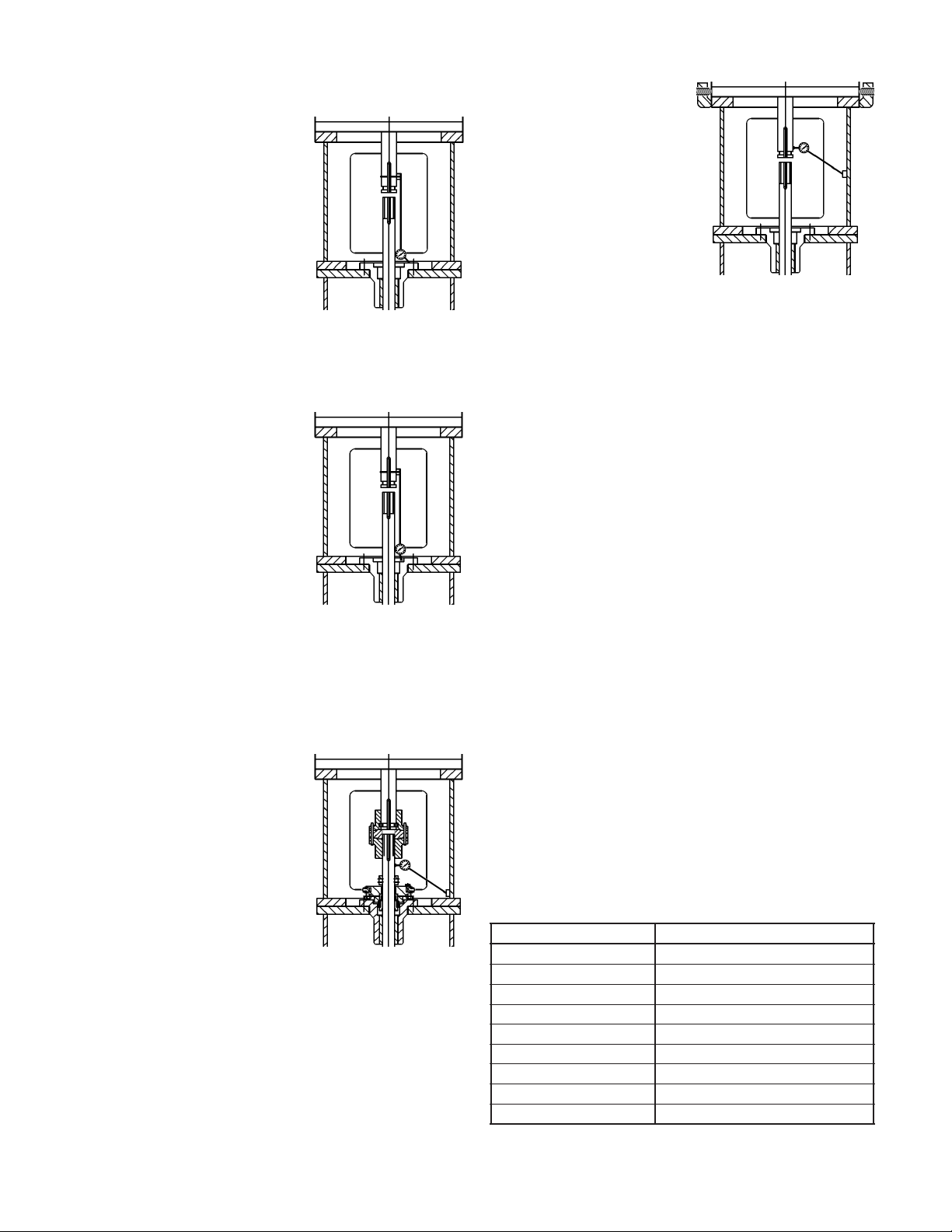
GENERAL DESCRIPTION
The model VIT pump is a vertical turbine lineshaft
pump, which is designed to meet wide ranges of service
with maximum dependability. See Figure 1 or Figure 2
for open lineshaft pump and Figure 3 and Figure 4 for
enclosed lineshaft pump.
Drivers
Hollow shaft motors or right angle gear drives, are often
used with a separate head shaft through the driver and
connected to the pump by a threaded coupling.
Column
Threaded or flanged column construction provides
positive shaft and bearing alignment. Bearings are spaced
to provide vibration free operation away from the
shaft critical speed in order to insure long bearing life
and reduced shaft wear. For open lineshaft, the shaft is
supported within the column by using bearing retainers
in the column assembly. For enclosed lineshaft, the
bearings are also the tube couplings of the shaft-enclosing
tube. The shaft-enclosing tube is stabilized in the column
pipe by tube stabilizer.
Bowl Assembly
The bowls are generally of flanged construction for
accurate alignment and ease of assembly and disassembly.
Impellers may be either open or enclosed depending on
the design requirements. They are fastened to the pump
shaft by taperlocks. For temperatures over 140º F
(60º C) and in the larger size bowls (over 18”), impellers
are keyed to the shaft. A special first stage low NPSH
impeller may be provided on some pump for certain
special application.
Thrust Pot
A thrust pot is utilized when the driver is not designed to
carry the pump thrust.
6
Page 7
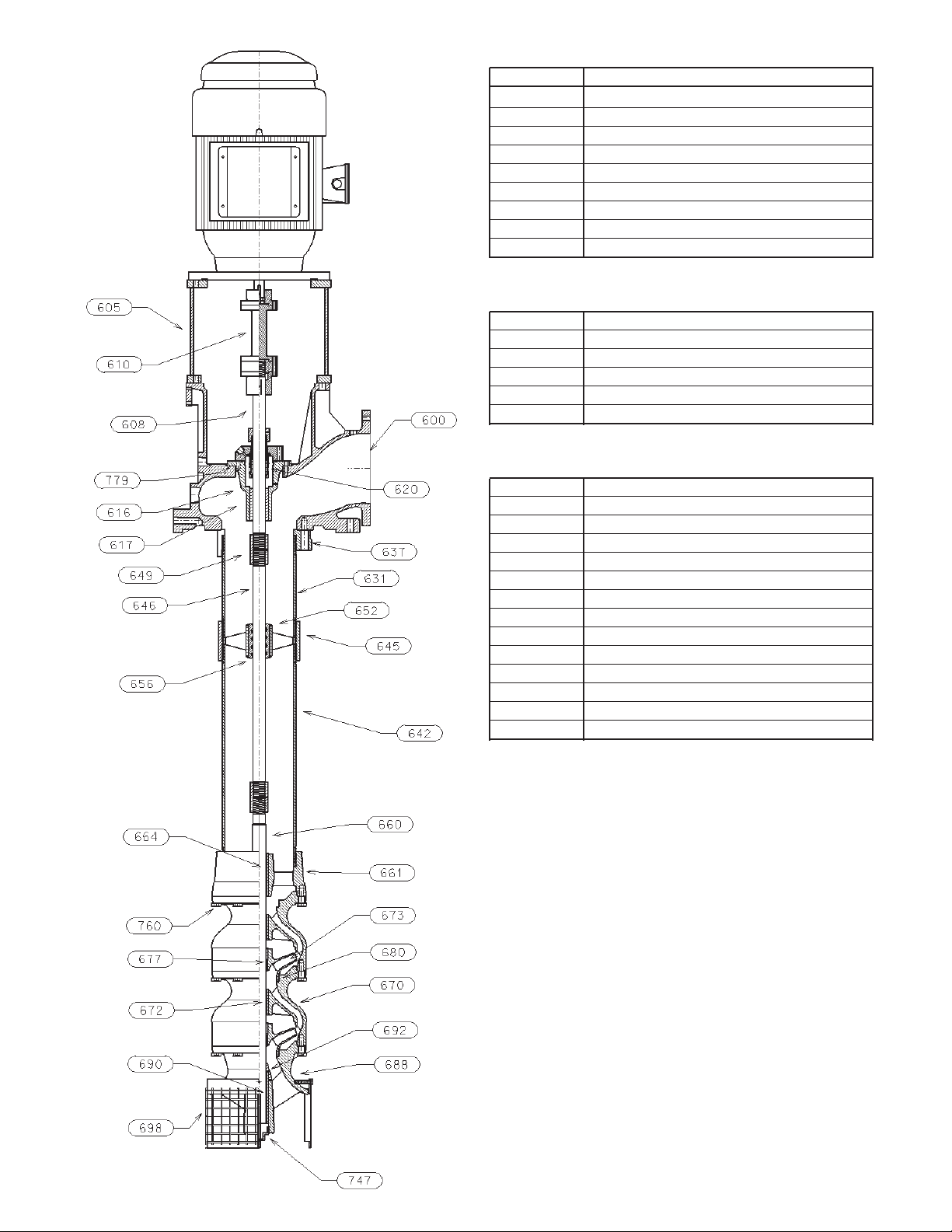
DISCHARGE HEAD ASSEMBLY
ITEM DESCRIPTION
600 DISCHARGE HEAD
601 MOTOR SUPPORT
608 HEADSHAFT
610 COUPLING ASSEMBLY
616 SEAL HOUSING
617 SEAL HOUSING BEARING
620 MECHANICAL SEAL
637 COLUMN FLANGE
779 SEAL HOUSING GASKET
COLUMN ASSEMBLY
642 COLUMN PIPE
645 COLUMN COUPLING
646 LINESHAFT
649 LINESHAFT COUPLING
652 BEARING RETAINER
656 LINESHAFT BEARING
BOWL ASSEMBLY
660 BOWL SHAFT
661 DISCHARGE BOWL
664 DISCHARGE BEARING
670 INTERMEDIATE BOWL
672 INTERMEDIATE BOWL BEARING
673 IMPELLER
677 TAPERLOCK
680 WEAR RING (OPTIONAL)
760 HEX BOLT
692 SAND COLLAR
688 SUCTION BOWL/BELL
690 SUCTION BEARING
698 SUCTION STRAINER
747 PLUG
Figure 1 Open Lineshaft Pump with
Threaded Column Pipe
7
Page 8
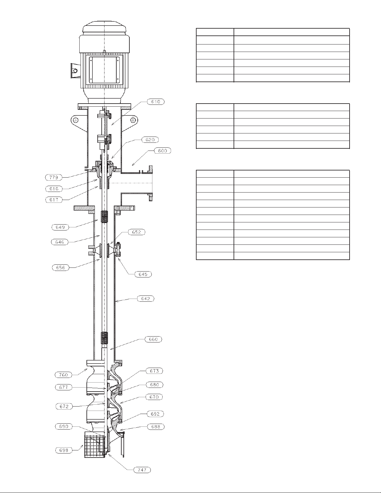
DISCHARGE HEAD ASSEMBLY
ITEM DESCRIPTION
600 DISCHARGE HEAD
608 HEADSHAFT
610 COUPLING ASSEMBLY
616 SEAL HOUSING
617 SEAL HOUSING BEARING
620 MECHANICAL SEAL
COLUMN ASSEMBLY
642 COLUMN PIPE
645 COLUMN BOLTING
646 LINESHAFT
649 LINESHAFT COUPLING
652 BEARING RETAINER
656 LINESHAFT BEARING
BOWL ASSEMBLY
660 BOWL SHAFT
670 INTERMEDIATE BOWL
672 INTERMEDIATE BOWL BEARING
673 IMPELLER
677 TAPERLOCK
680 WEAR RING (OPTIONAL)
760 HEX BOLT
692 SAND COLLAR
688 SUCTION BOWL/BELL
690 SUCTION BEARING
698 SUCTION STRAINER
747 PLUG
Figure 2 Open Lineshaft Pump
8
with Flanged Column
Page 9
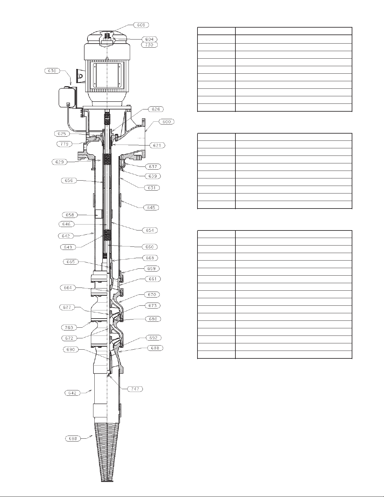
HEAD ASSEMBLY
ITEM DESCRIPTION
600 DISCHARGE HEAD
604 ADJUSTING NUT
608 HEADSHAFT
621 O-RING
625 TENSION PLATE
626 TENSION NUT
630 OILER
637 COLUMN FLANGE
730 GIB KEY
779 TENSION PLATE GASKET
COLUMN ASSEMBLY
629 TUBE NIPPLE
631 COLUMN NIPPLE
639 COLUMN LOCK RING
642 COLUMN PIPE
645 COLUMN COUPLING
646 LINESHAFT
649 LINESHAFT COUPLING
654 OIL TUBE
656 LINESHAFT BEARING
658 TUBE STABILIZER
BOWL ASSEMBLY
659 COLUMN ADAPTER
660 BOWL SHAFT
661 DISCHARGE BOWL
664 DISCHARGE BEARING
665 OIL SEAL
668 TUBE ADAPTER BEARING
670 INTERMEDIATE BOWL
672 INTERMEDIATE BOWL BEARING
673 IMPELLER
677 TAPERLOCK
680 WEAR RING (OPTIONAL)
688 SUCTION BOWL/BELL
690 SUCTION BEARING
692 SAND COLLAR
698 SUCTION STRAINER
747 PLUG
760 HEX BOLT
Figure 3 Enclosed Lineshaft Pump with
Threaded Column Pipe
9
Page 10
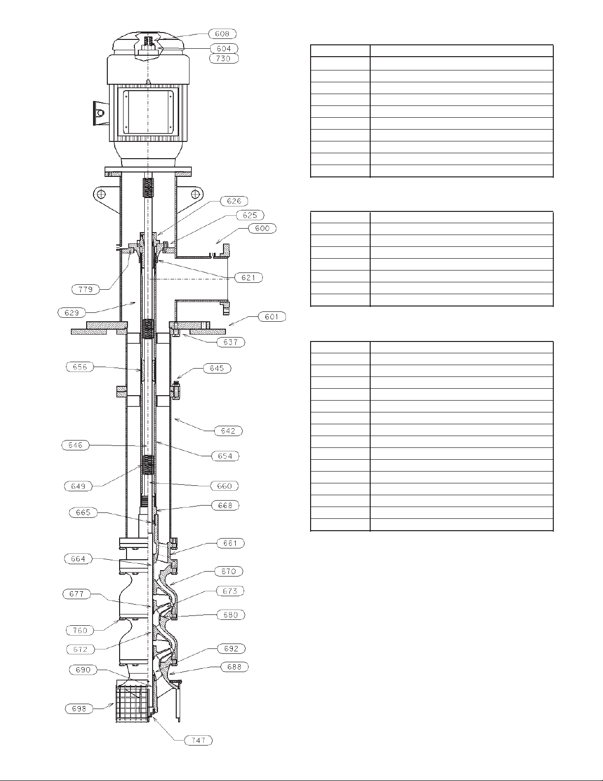
HEAD ASSEMBLY
ITEM DESCRIPTION
600 DISCHARGE HEAD
604 ADJUSTING NUT
608 HEADSHAFT
621 O-RING
625 TENSION PLATE
626 TENSION NUT
630 OIL RESERVOIR
637 COLUMN FLANGE
730 GIB KEY
779 TENSION PLATE GASKET
COLUMN ASSEMBLY
629 TUBE NIPPLE
642 COLUMN PIPE
645 COLUMN BOLTING
646 LINESHAFT
649 LINESHAFT COUPLING
654 OIL TUBE
656 LINESHAFT BEARING
658 TUBE STABLIZER
BOWL ASSEMBLY
660 BOWL SHAFT
661 DISCHARGE BOWL
664 DISCHARGE BEARING
665 OIL SEAL
668 TUBE ADAPTER BEARING
670 INTERMEDIATE BOWL
672 INTERMEDIATE BOWL BEARING
673 IMPELLER
677 TAPERLOCK
680 WEAR RING (OPTIONAL)
688 SUCTION BOWL/BELL
690 SUCTION BEARING
692 SAND COLLAR
698 SUCTION STRAINER
747 PLUG
760 HEX BOLT
10
Figure 4 Enclosed Lineshaft Pump with
Flanged Column
Page 11
Installation – SECTION 3
FOUNDATION AND PIPING
SUB BASE (SOLE PLATE) INSPECTION
Sub base and sole plate are terms in common use to
describe a general class of solid steel plates mounted
in grout (or bolted to steel structures) at the pumpfoundation interface.
5. Carefully lower the sub base onto the foundation
bolts. Hand tighten the nuts.
6. Leveling the sub base may be done by several
methods. Two common methods are:
A. Using leveling wedges. This is shown in
Figure 6.
B. Leveling nuts on the anchor bolts.
1. Remove the sub base from the pump discharge head,
when shipped assembled.
2. Completely clean the underside of the sub base. It is
sometimes necessary to coat the underside of the sub
base with an epoxy primer. (This is available as an
option.)
3. Remove the rust preventative solution from the
machined topside with an appropriate solution.
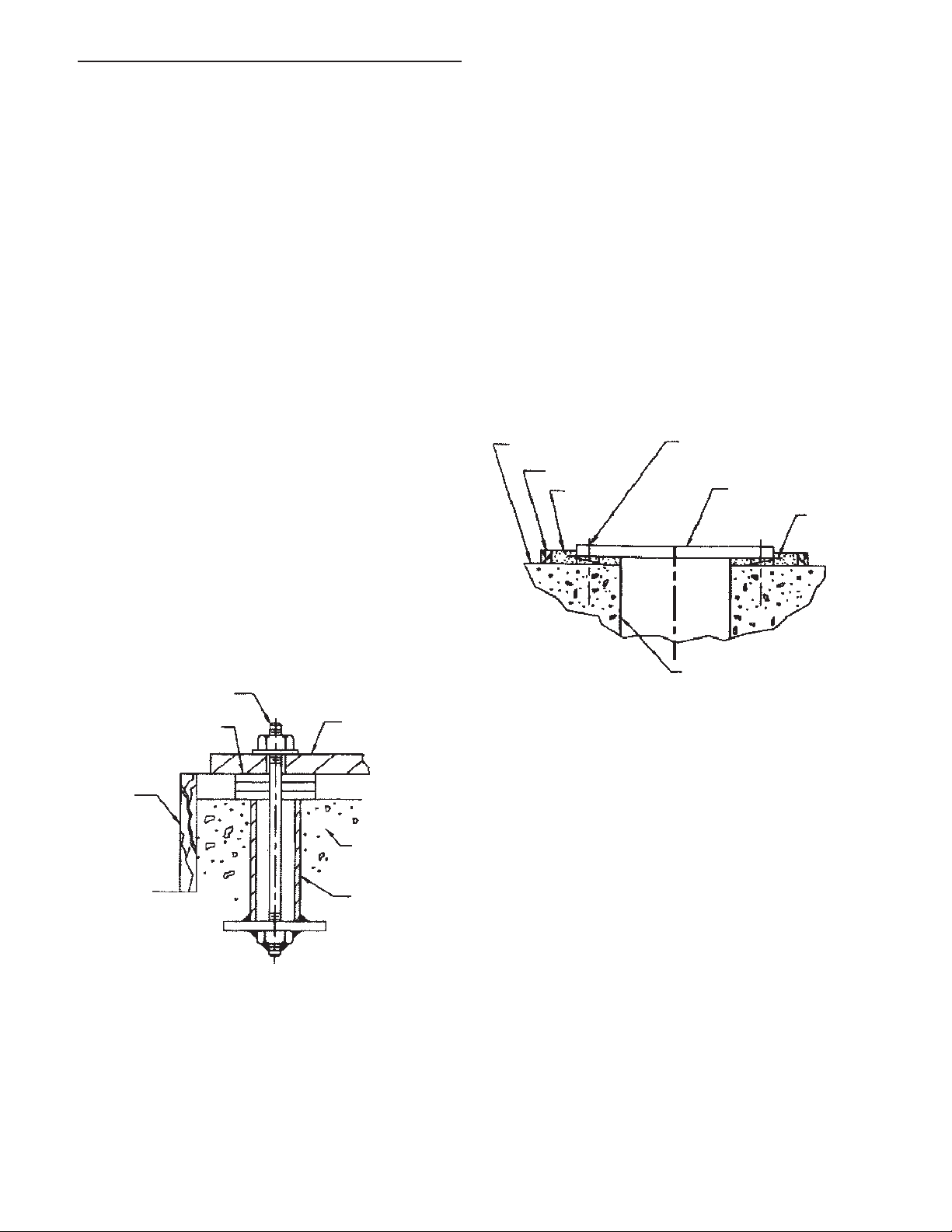
SITE WITH CONCRETE FOUNDATION
1. A pump should have adequate space for operation,
maintenance and inspection.
2. Sub base mounted pumps are normally grouted
on a concrete foundation, which has been poured
on a solid footing. The foundation must be able to
absorb any vibration and to form a permanent, rigid
support for the pumping unit.
3. The foundation must be of adequate strength to
support the complete weight of the pump, plus the
weight of the liquid passing through it. A typical
installation will have bolts with a pipe sleeve 2½
times the bolt diameter embedded in the concrete.
BOLT
SHIMS
SUB BASE
Regardless of the method, a machinist level must be
used for leveling.
NOTE: When using a machinist level, it is important
that the surface being leveled is free of all
contaminants, such as dust, to ensure an
accurate reading.
7. Level the sub base in two directions at 90 degrees
on the machined surface. The levelness tolerance
is 0.005 inches per foot for commercial, and 0.001
inches per foot for API.
FOUNDATION
DAM
GROUT
CENTERLINE
ANCHOR BOLT
SUB BASE
LEVELING
WEDGES
FLOOR SLEEVE
(OPTIONAL)
Figure 6
DAM
FOUNDATION
SLEEVE
Figure 5
Bolts should be sized and located in accordance
with the dimensions given on the Certified Pump
Outline Drawing, if provided. The pipe sleeve
allows movement for the final positioning of the
foundation bolts to conform to the holes in the sub
base flange. See Figure 5.
4. Remove water and/or debris from anchor bolt holes/
sleeves prior to grouting. If the sleeve type bolts are
being used, fill the sleeves with packing or rags to
prevent grout from entering.
SUB BASE GROUTING
1. Inspect foundation for dust, dirt, oil, chips, water,
etc. and remove any contaminants. Do not use oilbased cleaners as grout will not bond to them. Refer
to grout manufacturer’s instructions.
2. Build dam around foundation (See Figure 6).
Thoroughly wet foundation. Refer to grout
manufacturer’s instructions.
3. Pour grout between sub base and concrete
foundation, up to level of dam. Remove air bubbles
from grout as it is poured by puddling, using a
vibrator, or pumping the grout into place. Nonshrink grout is recommended. Refer to grout
manufacturer’s instructions.
4. Allow grout to set at least 48 hours.
5. Tighten foundation bolts.
PIPING
Guidelines for piping are given in the “Hydraulic
Institute Standards”, available from: Hydraulic Institute,
11
Page 12
9 Sylvan Way, Parsippany, NJ 07054-3802 and must be
WARNING
WARNING
CAUTION
reviewed prior to pump installation.
Never draw piping into place by forcing
the flange connections of the pump. Pipe
strain will adversely effect the operation of the pump
resulting in damage to the equipment and possible
physical injury.
to lower unit until the discharge head flange engages
and rests firmly on the plate, then secure with
capscrews provided.
5. When a lineshaft is shipped separately check shaft
for straightness; average total run out should not
exceed 0.005” TIR (0.127mm) for 10 feet (3m).
Shaft must be within tolerance prior to installation.
1. All piping must be supported independently of, and
line up naturally with the pump flange so that undue
pipe strain is not imposed on the pump.
2. DO NOT connect piping to pump until grout has
hardened and pump hold-down bolts have been
tightened.
3. It is suggested that expansion loops or joints, if used,
be properly installed in the discharge line. When
handling liquids at elevated temperatures expansion
joints are used, so linear expansion of piping will
not draw pumps out of alignment.
4. Carefully clean all pipe parts, valves and fittings,
and piping branches prior to assembly.
5. Isolation and check valves should be installed in
discharge line. Locate the check valve between
isolation valve and pump, this will permit inspection
of the check valve. The isolation valve is required
for regulation of flow, and for inspection and
maintenance of pump. The check valve prevents
pump or seal damage due to reverse flow through
the pump when the driver is turned off.
6. Increasers, if used, should be placed between pump
and check valves.
6. Refer to remainder of this manual for complete
assembly, startup, maintenance, disassembly and
recommended lubricants for the pump.
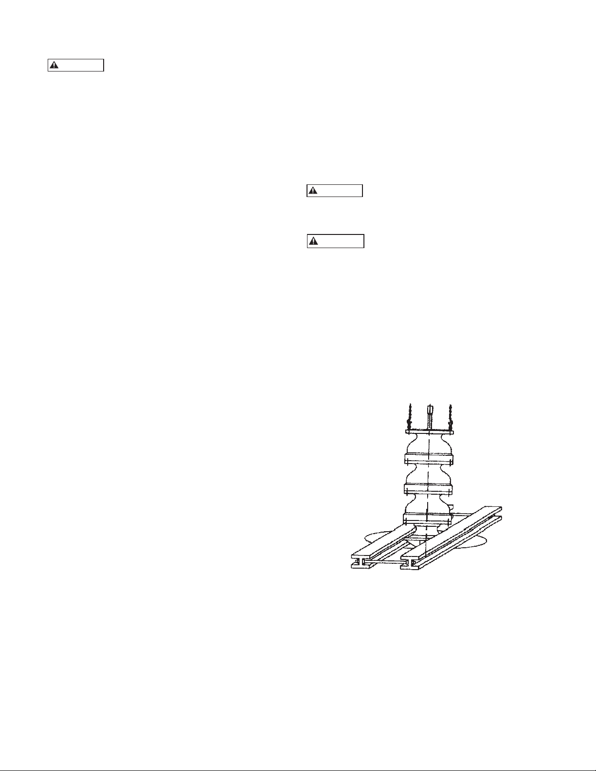
INSTALLING A PARTIALLY ASSEMBLED PUMP
Do not work under a heavy suspended
object unless there is positive support and
safe guards, which will protect personnel, should a hoist
or sling fail.
Do not attempt to lift bowl assembly
by the pump shaft. This can result in
damaging the pump shaft.
1. Prior to installing the bowl assembly, check that
all capscrews are tight. Turn the pump shaft by
hand and make sure it turns freely. Remove all
accumulated dust, oil or other foreign material from
the external surfaces.
2. Place two I-beam supports across the base plate
opening, strong enough to safely support the weight
of the entire pump assembly. These I-beams should
be connected by threaded rods and nuts so as to
clamp them firmly together to support the pump.
(See Figure 7).
7. Cushioning devices should be used to protect the
pump from surges and water hammer if quickclosing valves are installed in the system.
PUMP INSTALLATION
Pumps of 20 feet (6 meters) or less in length are usually
shipped assembled, with the exception of the driver,
mechanical seal with tubing and coupling assembly,
spacer or non spacer type. When provided, refer to the
Certified Pump Outline for the applicable base plate plan
for the location of anchor bolt holes.
INSTALLING AN ASSEMBLED PUMP
1. If a base plate was supplied, install as described in
Foundation/Piping Section (page 11).
2. Clean the mounting surface of the plate and clean
bottom surface of discharge head mounting flange.
3. Sling through discharge head holes or thread two
eyebolts through bolt holes in the mounting flange
and hoist unit into position over foundation.
NOTE: Eyebolts or sling should be rated to
handle in excess of the pump weight (See Outline
Drawing).
4. Lower the unit and carefully guide it so that unit
does not strike the side of the base plate. Continue
12
Figure 7
3. Place a suitable hoist or derrick over base plate
opening with the hook in the center.
4. If a suction strainer is provided, assemble it to the
suction bell (or suction bowl).
5. Place the elevator clamps just below the discharge
bowl. For flanged column install two threaded
eyebolts through the discharge bowl bolt holes 180º
apart for flanged column. For threaded discharge
utilize a lifting bail sized to handle the weight of the
bowl assembly and suction apparatus.
Page 13
6. Attach a sling to the elevator clamps, eyebolts,
CAUTION
CAUTION
CAUTION
CAUTION
or lifting bail and hoist it into position over the
foundation opening. (See Figure 7).
7. Carefully lower bowl assembly, guiding the unit so it
does not strike the sides of the opening. Continue
to lower bowl assembly until the elevator clamps
or discharge bowl flange rests firmly on the I-beam
supports.
8. Place a cover over the discharge bowl opening to
prevent entrance of dirt or other foreign matter
until ready for installation of the column assembly.
Do not drop any foreign object into the
bowl assembly. Such an object can cause
serious damage to the pump and any downstream
components. Any foreign object dropped into the bowl
assembly must be retrieved prior to continuing assembly.
COLUMN
OPEN LINESHAFT
Lineshafts are coupled with threaded or keyed couplings.
Column pipe may be threaded or flanged. When
provided, see the Certified Pump Outline Drawing for
the number of column and shaft sections required. The
top and bottom sections may be special lengths:
1. Check the lineshaft (646) for straightness. Average
total runout should be less than 0.0005” TIR per
foot, not to exceed 0.005” T.I.R. for every 10 feet of
shafting.
Bottom section of column pipe should not
be longer than 5 feet.
2. Hoist the first piece of lineshaft over the bowl
assembly. Lower the lineshaft until the bottom end
is properly aligned with the coupling of the pump
shaft. Apply a thin film of oil to the threads on the
lineshaft (646) and the coupling (649) (for nongalling material, or Molykote if galling material).
Use “MOLYKOTE” Dow Corning or
equal for all galling material such as
316 stainless steel.
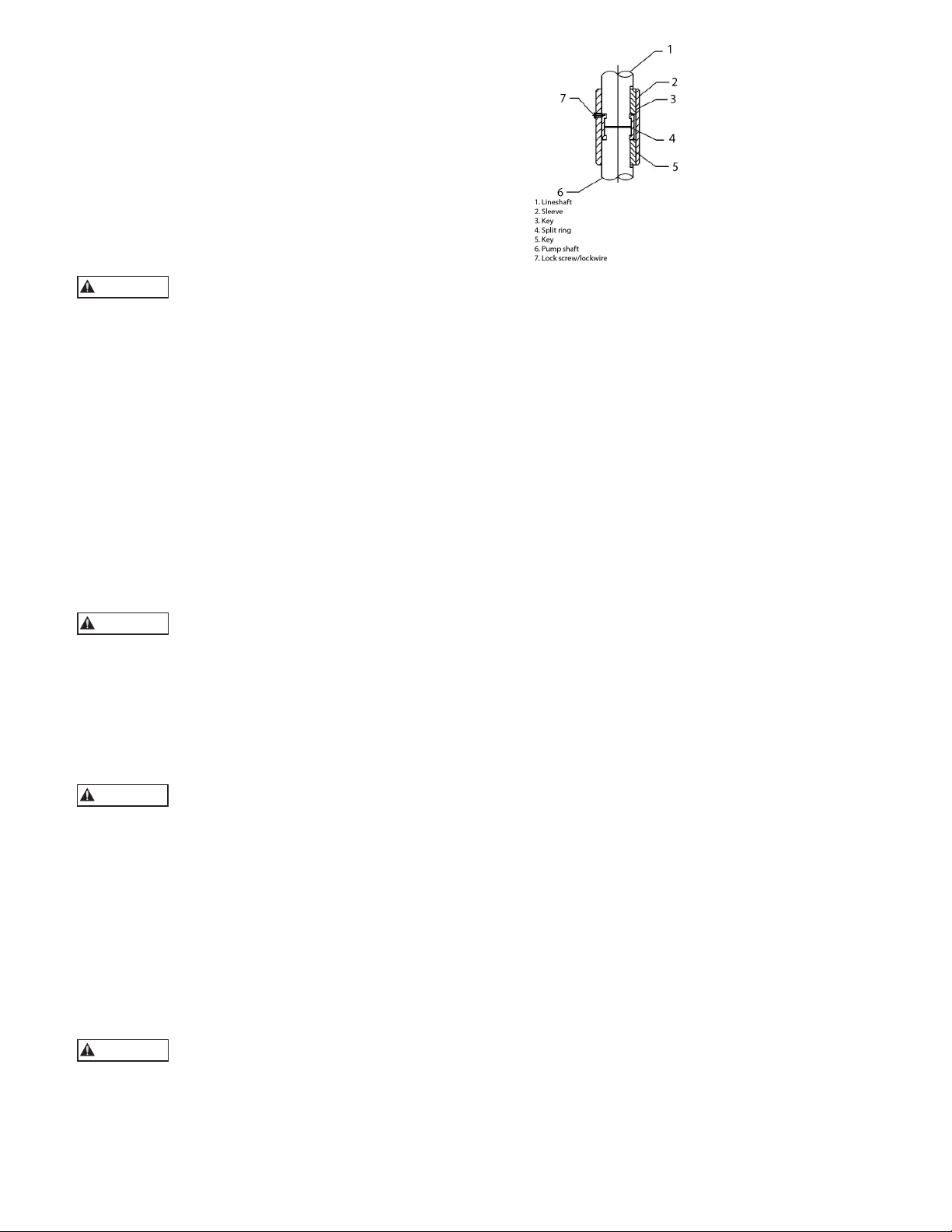
3b. With a keyed coupling
insert the key into the
pump shaft. Lower the
sleeve over the pump shaft,
to approximately 1.0 in
(25.4 mm) below the top
of the shaft. Then lower
the lineshaft until it touches
the pump shaft. Insert the
split ring into the grooves
of the pump shaft and
lineshaft. Raise the sleeve
until it covers the split ring,
then insert the key into the
lineshaft. Raise the sleeve to the top of the key and
secure the sleeve to the split ring with a lock screw
and lock wire.
4. For threaded column, secure a friction clamp
immediately below the column coupling. Hoist
column section over bowl assembly. Lower
column over lineshaft until column pipe engages
the discharge bowl. Manually screw the column
into discharge bowl. Complete joint by tightening
column with chain tongs until the end of the column
butts firmly against discharge bowl.
5. For flanged column, install two eyebolts
diametrically opposite the upper flange of the
bottom column. Attach a sling to the eyebolts and
to the hoist hook. Lower column section until the
flange engages the flanged top bowl register. Insert
as many bolts through both flanges as possible. Lift
column assembly high enough to allow rotation
of the supports. Install and tighten remaining
capscrews gradually in diametrically opposite pairs
until all are uniformly tightened.
6. Lift the assembly and remove the elevator clamp
or supports and slowly lower the bowl and the
column assembly. Place supports on the base plate
and continue to lower the assembly until the column
elevator clamps or column flange comes to rest on
the supports. Place an elevator clamp under the
column pipe and allow it to butt firmly against the
column pipe coupling.
3a. With lineshaft in the proper position on the
coupling, screw lineshaft into the coupling manually
until resistance is felt. A fine wire inserted in the
hole at the center of the coupling can be used as a
gage to determine when the coupling is correctly
positioned on the shaft. Remove the wire after
installing the shaft. Completely tighten the joint
by using a pair of pipe wrenches. Use care not to
damage any bearing journal areas on the shaft.
NOTE: Shaft threads are left-handed.
Make up threaded joints manually to
verify that the threads are properly
engaged prior to applying a wrench. If cross-threading
occurs, break the joint and repair the threads. If the
threads are beyond repair, replace the damaged part.
7. Place the bearing retainer over the shaft and locate
it in the column coupling recess. Make sure the
end faces of the column pipe are clean. For flanged
columns, fit the retainer in the female register of the
flange. Make sure the contact faces in the flanges are
clean.
8. Check that the shaft is approximately centered in
the bearing. Move the shaft around slightly so as to
center it in its bearing. Only a slight amount of force
should be required. If an excessive amount of force
is required, the pipe or shaft may not be butted
properly or the shaft may be bent. In any case, the
problem must be corrected prior to proceeding
further.
9. Repeat the preceding procedures until all column
sections required have been installed.
13
Page 14
10. Install the top shaft or stub shaft and coupling. If
CAUTION
CAUTION
CAUTION
the pump is equipped with column adjusting nipple,
install it with longer threaded end upward. Screw
the lock ring on to the nipple until you reach the
end of the thread.
Do not drop any foreign object into the
column assembly. Such an object can
cause serious damage to the pump and any downstream
components. Any foreign object dropped into the column
assembly must be retrieved prior to continuing assembly.
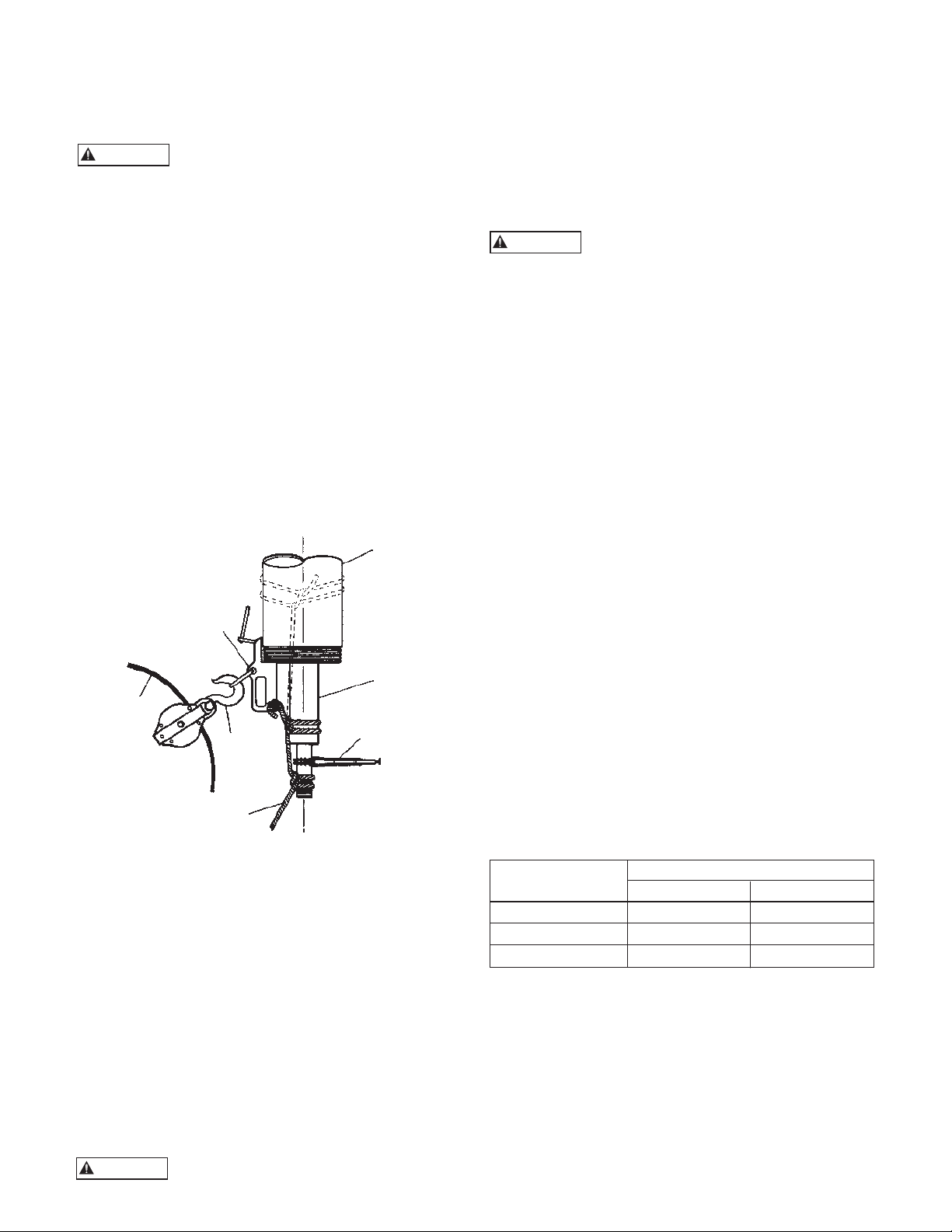
ENCLOSED LINESHAFT
1. Insert tube (654) and shaft (646) sections into
column section.
7. With lineshaft in proper position on the coupling,
remove tail rope and screw lineshaft into coupling
until resistance is felt. A fine wire inserted in the
hole at the center of the coupling can be used as a
gage to determine when the coupling is correctly
positioned on the shaft. Remove the wire after
installing the shaft. Completely tighten the joint
by using a pair of pipe wrenches. Use care not to
damage any bearing journal areas of the shaft.
NOTE: Shaft threads are left-handed.
Make up threaded joints manually to
verify that the threads are properly
engaged prior to applying a wrench. If cross-threading
occurs, break the joint and repair the threads. If the
threads are beyond repair, replace the damaged part.
2. Place an elevator clamp near top of column just
below and butt firmly against column pipe coupling
(645). For flanged columns, place the elevator clamp
just below the flange.
3. Attach a sling to hoist hook. Attach bottom of shaft
(646) to column (644), by tying a tail rope to deepthroated clamp attached to bottom of column. (See
Figure 8). Tie a clove hitch or double half hitch
around the enclosing tube and then around the shaft
in threaded area. Figure 8 also shows the alternate
method (dotted lines).
COLUMN
DEEP THROATED CLAMP
ENCLOSING
DRAG LINE
HOIST
HOOK
ROPE
TUBE
CHAIN WRENCH
(CLAMP)
Figure 8
4. Utilize the remaining tail rope to keep tension on
the knots during hoisting. Lower end of column
section shall be guided by a drag line which is pulled
by the hoist. A traveling block for the drag-line
shall be attached to a deep-throated clamp, which is
secured to bottom of the column threads.
8. Carefully lower column section until lower end
of the tube section rests on the adapter bearing
(668). The end faces of the tube should be clean
and free of nicks. Remove tail rope, clean outside
of the adapter bearing and lubricate with thread
compound. Screw tube section onto adapter bushing
manually, until resistance is felt. Complete tube joint
by utilizing a pair of pipe wrenches or chain tongs,
butting the end of tube against the upper end of the
tube adapter bearing.
9. Clean column threads and lubricate with thread
compound.
10. Lower column until column pipe engages in the
discharge bowl. Manually thread the column into
discharge bowl. Complete joint by tightening
column, utilizing chain tongs until the end of the
column butts firmly against discharge bowl.
11. Lift the pump assembly and remove elevator clamp
secured to discharge bowl. Slowly lower assembly
into well or sump until elevator clamp gently comes
to rest on timbers or I-beam supports and remove
the sling.
12. Remove the exposed lineshaft bearing, pour oil into
the tubing and reinstall the bearing. The amount of
oil to be poured is given in the following table:
Tube Size
Amount of oil per section
10 ft. Sections 20 ft. Sections
1¼, 1½, 2 ½ Cup 1 Cup
2½, 3, 3½ 1 Cup ½ Qt.
4 and larger ½ Qt. 1 Qt.
5. Hoist column section over pump, keeping tension
on tail rope. With column in a vertical position,
remove drag-line and traveling block, lower column
until bottom line shaft is properly aligned with
pump shaft coupling.
6. Apply a thin film of oil to the threads on the
lineshaft (646) and the coupling (649) (for nongalling material or Molykote if galling material).
Use “MOLYKOTE” Dow Corning or
equal for all galling material such as 316
14
stainless steel.
See page 27 for recommended oil.
13. Repeat the preceding procedures. Throughout the
column assembly, install tube stabilizer (658) over
the enclosing tube (654) every 40 feet. The last one
should be less than 20 feet below the bottom of the
discharge head. Use soapy water as lubricant when
sliding the stabilizer over the tube.
14. Continue the procedure until all column sections
for the proper setting have been installed, excluding
the column adjusting nipple (631) and tube nipple
(629), if provided.
Page 15
CAUTION
CAUTION
CAUTION
15. Install the top shaft or stub shaft and coupling.
Do not drop any foreign object into the
bowl assembly. Such an object can cause
serious damage to the pump and any downstream
components. Any foreign object dropped into the bowl
assembly must be retrieved prior to continuing assembly.
INSTALLING THE DISCHARGE HEAD
VIT Pumps are provided with either a cast iron or
fabricated steel type head. For pump with below
ground discharge, a motor stand is provided instead the
discharge head. Install the discharge head as follows:
1. If the stuffing box (See Fig. 9) or tension nut (See
Fig. 10) is assembled to the head, remove it and all
the attached piping.
2. For threaded column, check to be sure that the
column flange (637) is securely attached to the
bottom of the discharge head. Check and tighten
the capscrews (or socket head screw) gradually in
diametrically opposite pairs.
3. Remove coupling guard if provided. Attach a sling
to the lifting lugs on the side of the discharge head
through windows and hoist discharge head over the
protruding top shaft (or stub shaft).
Do not bump or scrape the shaft protruding above the column. This could result in
bending or damaging the shaft.
4. Orient the discharge head in the required position
and lower the head. Center the vertical hole with
the top shaft protruding above the column. For
threaded column, continue to lower the discharge
head until the large threaded hole in the bottom
of the discharge head rests squarely on top of
column. Clean the threads at upper end of column
assembly and lubricate with thread compound.
Rotate discharge head, screw it onto the column,
for short set-pump, (without the column adjusting
nipple) butting the top of column tightly against the
discharge head.
5. For flanged column, continue to lower the discharge
head until the discharge head engages the column
flange. Install capscrews and secure discharge head
to the column flange. Tighten capscrews gradually
in diametrically opposite pairs. Lift the pump
assembly high enough to allow rotation of the
supports. Realign and lower assembly. Install and
tighten remaining capscrews. Repeat the rotating
and the tightening procedure until all capscrews are
uniformly tight.
6. Hoist the discharge head by lifting lug and remove
the elevator clamp attached to column.
7. Remove the support timbers or I-beams and clean
the top of foundation or base plate. Orient the
discharge head in the required position.
NOTE: Sling should be rated to handle in excess of the
pump weight.
8. Lower bowl, column and head assembly, until
discharge head mounting flange engages base plate.
Secure discharge head to the foundation or base
plate. Check the levelness of the discharge head in
all directions, utilizing a machinist level across the
driver’s mounting surface of the discharge head.
9. Check whether the top shaft (or stub shaft) is in the
center of the stuffing box bore. If not, the shaft must
be centered by shimming the head base and the sub
base (or the foundation).
10. Rotate the shaft approximately 90º. Check again
whether the shaft is at the center of the stuffing box
bore or not. If not, either the top shaft is bent or the
first shaft below it did not butt properly. Correction
must be made before the installation procedures can
proceed.
INSTALLING THE STUFFING BOX
Assemble stuffing box as shown in Figure 9.
1. Clean the surface of the discharge head where
the stuffing box will be mounted and remove
any nicks or burrs with a fine flat file. Position
gasket on surface. Slide stuffing box (616) down
over headshaft and into position on the gasket.
Secure stuffing box with capscrews. Make sure
the capscrews are torqued equally to prevent
misalignment.
2. Grease the packing ring (620) for easier installation.
3. Twist the packing ring sideways to get it around the
shaft easily. Start the first ring into the stuffing box.
When the entire ring is worked in using the fingers,
tamp it down using a split wood bushing (or equal)
and push the packing ring down firmly. It must seal
on the shaft and bore of the stuffing box. Install all
three (3) rings in this manner. Stagger ring joints 90º
apart. The split gland may be used as a tamper for
the top ring.
4. Insert lantern ring (622) into stuffing box. Be sure
it is properly positioned so that it aligns with the
lubrication passage in the stuffing box.
5. Insert three (3) additional rings of packing. Stagger
ring joint 90º apart.
6. Install the split gland and screw nuts on the split
gland studs. Tighten nuts then relieve the nuts and
tighten finger tight.
Check that the split gland is square in the
stuffing box. Cocking can cause uneven
compression of packing and damage to the shaft or sleeve
and heat up the shaft and stuffing box.
(619) STUD (2)
(735) HEX NUT
(2)
PORT “A”
(622) LANTERN
RING
Figure 9
(624) BYPASS LINE
(618) GLAND
PORT “B”
(621) O-RING
(620) PACKING
(6 RING)
(616) STUFFING
BOX
(617) BEARING
15
Page 16
7. The stuffing box is shipped with both ports plugged.
CAUTION
CAUTION
CAUTION
If the discharge pressure is over 100 psi, remove the
plug on Port “A” and attach a bypass (relief) line. If
the discharge pressure is over 200 psi, remove the
plug on Port “B” and attach another bypass line.
8. Final adjustment of the stuffing box must be made
at pump start up. A properly packed stuffing box
should be loose enough to allow the shaft to be
turned manually. Also, packing must allow leak.
See page 24, Pump Start Up #5.
Do not over tighten packing or excessive
wear can occur on the shaft or sleeve.
INSTALLING THE MECHANICAL SEAL
Vertical turbine pumps are usually supplied with cartridge
type mechanical seals, shipped assembled - ready
for installation, when mechanical seals are supplied.
Instructions for installing mechanical seals are provided
by the seal manufacturer. Consult the seal manufacturer’s
instructions (furnished with the seal) for information
on the type of seal used. Additionally, refer to factory
furnished outline drawing and seal piping schematic on
complex seal piping arrangements.
GENERAL REQUIREMENTS FOR INSTALL SEALS
1. Check surfaces at the face of the seal housing and at
the bottom of the seal housing to insure that they are
clean, flat and free of burrs. The face surface must be
smooth to form a good sealing surface for a gasket
or O-ring.
2. Check that shaft is smooth, and free of burrs, nicks
and sharp corners that could nick or cut the O-ring
or shaft packing. When further clean up is required,
protect by covering the inside of the pump seal
housing. Remove burrs, nicks and sharp corners by
using a strip of emery cloth over the shaft threads.
File threads around the keyway with a smooth mill
file or emery cloth. Sharp edges must be rounded.
3. Remove all chips and dust from the shaft area.
4. Check that all rotary unit parts of the seal fit over
the shaft. A pre-check may be made by removing the
O-ring(s) from the cartridge sleeve Inside Diameter
(ID) and then installing the seal on the shaft. Further
shaft clean up will be necessary when the seal will
not pass all the way into the seal housing.
5. Remove the seal after the pre-check and re-install
the sleeve O-ring(s).
6. Sparingly lubricate the shaft and sleeve ID with
the lubricant included with the mechanical seal or
recommended by the mechanical seal manufacturer.
The following lubricants may be used, for
water service, when no lubricant is supplied or
recommended by the mechanical seal manufacturer.
• Light oil (SAE #10 or 20)
• Dow Corning #4 Grease
• Silicone lubricant
• Wax or Clay
• Soapy water
7. Install the O-ring or gasket, between the seal
housing and seal. Install the seal over the shaft and
ease it into position against the face of the seal box.
Take care when passing the sleeve and O-ring over
keyways or threads to avoid damaging the O-ring.
Do not bump carbon members against The
shaft as they may chip, crack or break.
8. Position seal gland on discharge head seal housing
and secure with capscrews (or nuts for studs)
provided. Tighten capscrews gradually and
uniformly in a criss-cross pattern, taking 2 or 3
passes.
Do not over tighten capscrews on gland.
This can distort seal seat and cause seal
failure.
9. Install all seal piping as required. Prior to making
final connections of sealing liquid pressurizing lines,
make sure the seal housing and all sealing liquid
lines are flushed free of dirt, scale and other particles
that would be abrasive to the sealing faces.
10. The Driver and Coupling must now be installed
per instruction. (See page 24 - INSTALLING
THE HOLLOW SHAFT DRIVER or page 26 INSTALLING THE SOLID SHAFT DRIVER).
MECHANICAL SEAL ALIGNMENT
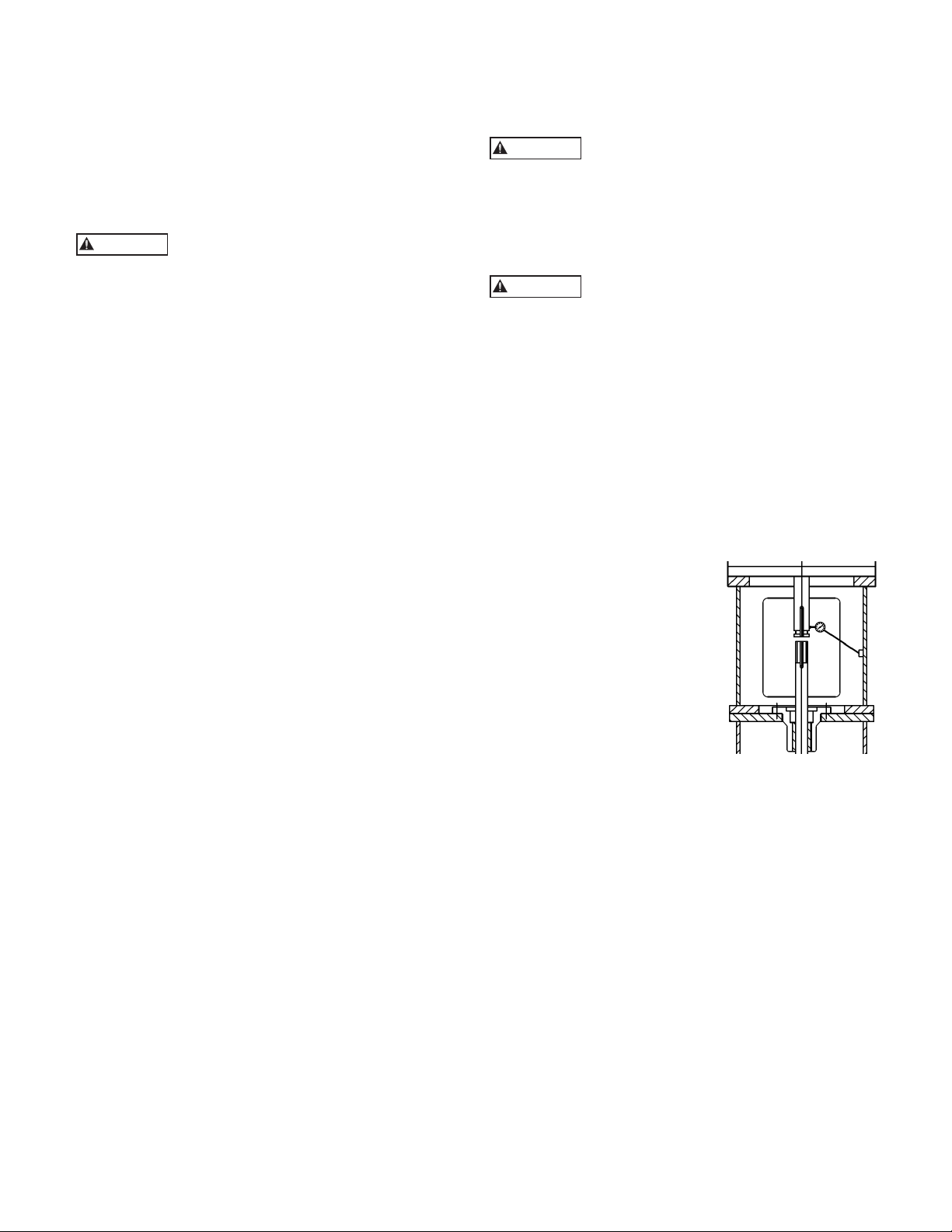
CONCENTRICITY OF MOTOR SHAFT
1. Install the dial indicator
as shown, with the base
attached to the motor
support.
2. Rotate the motor shaft by
hand while you read the
dial.
3. Make sure that the runout
does not exceed NEMA
standards, 0.002 in (0.05
mm) maximum TIR.
4. If the indicator reads higher than 0.002 in (0.05
mm)TIR, loosen the four motor hold-down bolts
and relocate the motor on the motor base register.
5. Obtain the desired position.
6. Tighten the hold-down bolts and repeat the indicator
reading.
Note: Adding or removing shims between the motor
and the discharge head helps alignment in the
vertical direction. The motor may also have to be
adjusted in the horizontal direction for alignment.
Oil based lubricants will damage EPR / EPDM
elastomer O-rings. Silicone lube and soapy water are
safe for EPR / EPDM elastomer O-rings.
16
Page 17
FLATNESS OF THE SEAL HOUSING
For this measurement, remove the mechanical seal if
the dial indicator stylus cannot rotate 360° on the top
surface of the seal gland.
1. Install the dial indicator as
shown, with the base 1)
Remove the lower coupling
components and attach the
base of the dial indicator to
the motor shaft.
2. Place the stylus at the top
surface of the seal gland, or
at the top surface of the seal
housing.
3. Slowly rotate the motor
shaft 360°.
4. Check that the face of the seal housing is square
with the shaft to within 0.002 in (0.05 mm) TIR.
CONCENTRICITY OF THE SEAL HOUSING
This measurement requires that
you remove the mechanical seal.
1. Install the dial indicator as
shown.
2. Rotate the motor shaft
by hand and run the
indicator in the insidemachined surface of the
seal housing in order to
determine the concentricity.
3. If the indicator reads higher
than 0.004 in (0.10 mm) TIR, loosen the four
motor hold-down bolts and relocate the motor on
the motor base register.
4. Obtain the desired position.
5. Tighten the hold-down bolts and repeat the
indicator reading.
CONCENTRICITY OF THE HEADSHAFT
1. Reinstall the mechanical
seal if it was removed for
the flatness or concentricity
measurement.
2. Install the coupling assembly
and adjust the impeller.
3. Attach the base of the dial
indicator on the discharge
head or motor support.
4. Place the stylus on the shaft
between the top of the seal
and the bottom of the pump coupling.
5. Slowly rotate the motor shaft 360°.
6. Check that the shaft runout is within 0.004 in (0.10
mm) TIR, or as required by specification.
7. Drill and dowel the pin in three places in order to
secure the motor to the motor base after you obtain
the required runouts.
CONCENTRICITY OF MOTOR SHAFT USING
JACKSCREWS
1. Install the dial indicator
as shown, with the base
attached to the motor
support.
2. Rotate the motor shaft by
hand while you read the
dial.
3. Make sure that the runout
does not exceed NEMA
standards, 0.002 in (0.05
mm) maximum TIR.
4. If the indicator reads higher than 0.002 in (0.05
mm) TIR, using the jackscrews relocate the motor
on the motor base (sometimes no register).
5. Obtain the desired position.
6. Tighten the hold-down bolts (not the jackscrews)
and repeat the indicator reading.
Note: Adding or removing shims between the
motor and the discharge head helps alignment in
the vertical direction. The jackscrews are provided
to adjust the motor in the horizontal direction for
alignment.
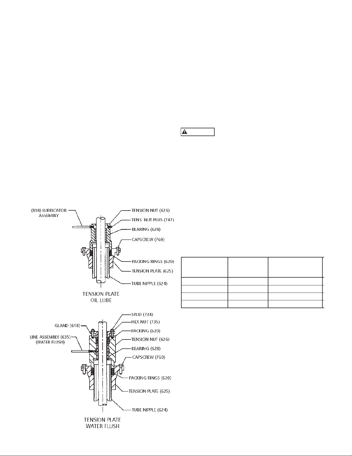
INSTALLING THE TENSION PLATE WITH CAST IRON
TENSION NUT
INSTALLING THE TUBE TENSION PLATE
1. (See Figure 10). Lubricate tube threads and
underside of tension plate flange with thread
compound. Thread the tension plate (625) onto
the enclosing tube nipple (629) manually until its
shoulder rests on the discharge head.
TENSIONING THE ENCLOSING TUBE
The enclosing tube sags from its own weight as it is
installed and must be pulled tight (tensioned) to make it
straight. This section describes two methods of tensioning
the tube. The direct pull method is more precise and is
preferred. The second method--the wrenching method--is
given as an alternate.
NOTE: The correct tension is equal to the weight of the
enclosing tube plus 10%.
Weights per unit length for each tube size are given in the
Table 1. Multiply by total length of the tube to determine
the total weight.
TABLE 1 – Weight-per-foot of Enclosing Tubing
TUBE SIZE (INCH) WEIGHT PER FOOT (LB.)
1¼ 2.99
1½ 3.63
2 5.02
2½ 7.66
3 10.25
3½ 12.50
4 14.98
5 20.78
6 28.57
17
Page 18
DIRECT PULL METHOD
CAUTION
1. The upper end of the tube may be pulled by the
hoist to obtain the predetermined tension value.
This requires the use of a dynamometer scale and
an adapter fitting to grip the tube. TUBE TENSION
ADAPTER AVAILABLE THROUGH FACTORY.
With the tension plate installed manually but
not tightened, thread the special fitting onto the
top of the tube to full engagement. Attach the
dynamometer scale to the fitting, and connect the
upper end of the scale to the hoist hook. Operate
the hoist hook to apply the required tension. This
should pull the tension plate off the discharge head.
Manually thread the tension plate to reset it. Release
tension, remove dynamometer scale and special
fitting.
WRENCHING METHOD
1. If a dynamometer is not available, the tube can
be tensioned by wrenching the tube tension
plate. Make up a spanner wrench to straddle the
projecting threaded tube end and to engage the tube
tension plate capscrew holes by two lugs. Torque
the tension plate to take all the slack out of the shaft
tubing and induce a reasonable amount of tension
by turning the tension plate counterclockwise. For
tubing 2½” (63.5mm) and larger, an individual's full
strength on a 3 foot (915mm) lever arm is sufficient.
For smaller sizes, less pull must be exercised.
NOTE: Do not turn clockwise to align holes in tension
plate and discharge head.
INSTALLING TENSION NUT
1. (See Figure 10). Install capscrews (760) in the
tension plate. Pour one pint of oil down the oil
tube. Note: Factory assembled unit has no oil in it.
Oil must added in the field.
2. Install packing (620) in the tension plate and thread
the tension nut (626), tightening it firmly against the
packing.
3. If a packed type tension nut (626) is used (for water
flush), install packing (620), packing gland (618)
and secure with stud (734) and nut (735). Screw nut
finger tight. Install line assembly (635) and connect
to flush liquid supply (see Figure 10).
Be sure that the top of the enclosing tube
does not interference with the tension nut.
4. If the top of the tube interferes with the tension nut,
determine the distance, if the tube is too long or too
short. If the tube is too short, it must be replaced
with a longer tube of the correct length. If the tube
is too long, it must be cut to the correct length and
re-threaded. Reinstall and re-level pump.
LUBRICATION SYSTEM
1. Connect solenoid valve (if provided), oil lines, and
fill the oil reservoir with oil.
2. Check the lubricator feed and see that the oil
reservoir is flowing freely. (In the case of a solenoid
valve, temporary power connections are required.)
Set the proper drops per minute on the regulator.
Table 2 shows recommended regulator setting.
TABLE 2 – Regulator Setting
Shaft Size Basic drops
100 ft. setting
(in.) per minute
Additional drops
per minute per
0.75 - 1.18 5 2
1.50 - 1.68 7 3
1.94 - 2.43 10 4
2.68 and larger 12 5
INSTALLING THE TENSION PLATE WITH BRONZE
TENSION NUT
Assemble Tension Plate Assembly as shown in Figure 11.
1. Remove the lock bolt (636) and o-ring (621).
Thoroughly clean the tension plate (625) include the
o-ring groove. Lightly grease the o-ring and re-install
it.
2. Clean the surface of the discharge head where the
tension plate will be mounted and remove any nicks
or burrs with a fine flat file. Clean the O.D. of the
tube nipple. Carefully install the tension plate and
gasket (779). Evenly tighten the mounting capscrews
(759F).
3. Pour one pint of recommended oil down the tube
nipple (629). (See page 27 for recommended
lubricants.) Note: Factory assembled unit has no oil
in it. Oil must be added in the field.
Figure 10
18
Page 19
CAUTION
WARNING
LUBE LINE
(635)
LOCK BOLT
(636)
TENSION NUT
(623)
CAPSCREWS
TENSION PLATE
(625)
GASKET
(779)
O-RING
(621)
TUBE NIPPLE
(629)
Figure 11
4. Clean the tension nut (623) and lightly oil its bore
and the threads. Screw the tension nut into the tube
nipple until the flange face of the nut contact the
tension plate.
5. For setting less than 100 feet, tighten the tension nut
until a slot aligns with the nearest locking position.
Install the locking bolt.
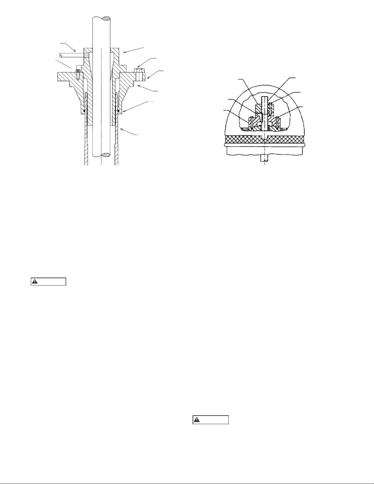
INSTALLING THE DRIVER
INSTALLATION OF A HOLLOW SHAFT DRIVER
This refers to either VHS type electric motors or hollow
shaft type gear drives. A small paragraph will be devoted
to combination electric motor and right angle gear
drives.
Do not work under a heavy suspended
object unless there is a positive support
and safe guards which will protect personnel should a
hoist or sling fail.
1. The driving mechanism of all hollow shaft driver is
shown on Figure 12. The head shaft (608) extends
up through the quill or hollow shaft of the driver
and is held in place by an adjusting nut (604), which
not only carries all the static and hydraulic thrust
of the impellers and shaft, but also provides the
adjustment for the impeller clearances. The head
shaft is connected to top shaft (or stub shaft) by a
threaded coupling or a rigid flange coupling.
2. When a motor stand is furnished and not installed,
proceed as follows:
A. Hoist the motor stand, inspect the mounting
surfaces, register and clean these surfaces
thoroughly.
B. Install the motor stand on discharge head and
secure with capscrews provided.
3. Attach a sling to the lifting lugs of driver and hoist
the driver up. Inspect the mounting surface, register
and clean these surfaces thoroughly. If any burrs
are found, remove burrs with a smooth mill file,
cleaning thoroughly afterward.
4. For motor, orient the motor conduit box in the
required position. For the right angle gear, orient
the input shaft to the desired position. Align the
driver mounting holes with the mating tapped holes
on the discharge head. Lower the driver until the
registers engage and the driver rests on the discharge
head. Secure driver with capscrews provided.
5. Lubricate the driver bearings in accordance with
instructions given on lubrication plate attached to
the driver case (or in the motor IOM).
(604) ADJUSTING
NUT
(730) GIB KEY
DRIVE
COUPLING
HEADSHAFT (608)
CAPSCREW (760)
ADJUSTING NUT
HOLD DOWN
BOLT
Figure 12
6. After lowering and orienting the driver as explained
above, remove the drive coupling and the hold
down bolts (See Figure 12). Be sure to mark the
location of the coupling before removing it.
7. Lower the head shaft through the motor quill shaft
to meet the shaft coupling. Apply a thin film of oil
to head shaft threads (if non-galling material) and
screw into the shaft coupling (located above the
stuffing box). Make sure the shaft is not damaged in
any way. Tighten the joint.
8. Check that the head shaft centers inside the driver
quill shaft within 0.06” (1.5 mm). If it does not,
misalignment is indicated.
9. Any head shaft misalignment with driver quill
shaft could be caused by a bent headshaft, burrs,
or foreign matter between shaft ends or any of the
mounting flanges: motor flange to discharge head
top flange, discharge head base flange to base plate
or the base plate itself could be out of level. If the
latter, shimming between base plate and discharge
head base, will correct it. Also, check concentricity
of motor to motor-stand (if provided) to discharge
head.
10. With the motor in place and the head shaft
projecting through the motor quill shaft, make
temporary electrical connection to check the motor
rotation. (Be sure to remove the ratchet pins or balls
before checking motor rotation.) Motor must rotate
counter-clockwise when viewed from the top. See
arrow on pump name plate. If motor does not rotate
counter-clockwise, you can change the rotation by
interchanging any two leads. (For three phase only.
For single phase motors see motor manufacturer’s
instructions.)
Never check motor rotation with the drive
coupling in place. The bore clearance
between the drive coupling and the pump shaft O. D.
is so close that should the motor spin with this shaft
stationary, galling and locking together is very likely to
take place.
19
Page 20
11. Install motor drive coupling. (Be sure to line up the
WARNING
match mark made at step 6.) Inserting the ratchet
pins if a non-reverse ratchet is used. Match the
coupling lugs with corresponding holes in motor.
Tighten hold down bolts evenly, making sure driver
coupling is properly seated in the register fit.
12. Fit gib key (730) into keyway, by filing if necessary,
to where there is a snug but sliding fit. This key
must be able to be removed by gentle leverage with
a screwdriver under it.
13. Be careful that the gib key (730) is not too high so
as to hold up the adjusting nut (604) from seating
on the drive coupling. If it is, cut off some length of
the key.
14. Install adjusting nut (604) to hand tight.
COMBINATION ENGINE AND MOTOR DRIVES
1. On combination drivers, the motor is invariably on
top with a projecting head shaft extension.
2. Follow all procedures outlined in the previous
paragraph, except that the motor must be lowered
over this extended head shaft and great care must be
taken to center it exactly so as not to bump or misalign the shaft while the motor is being lowered into
place.
3. There are several methods of running engines
without electric motors and vice versa, requiring
simple adjustment to the combination drive, but
they are too numerous to mention here and can be
obtained from the gear manufacturers instructions
included with the shipment.
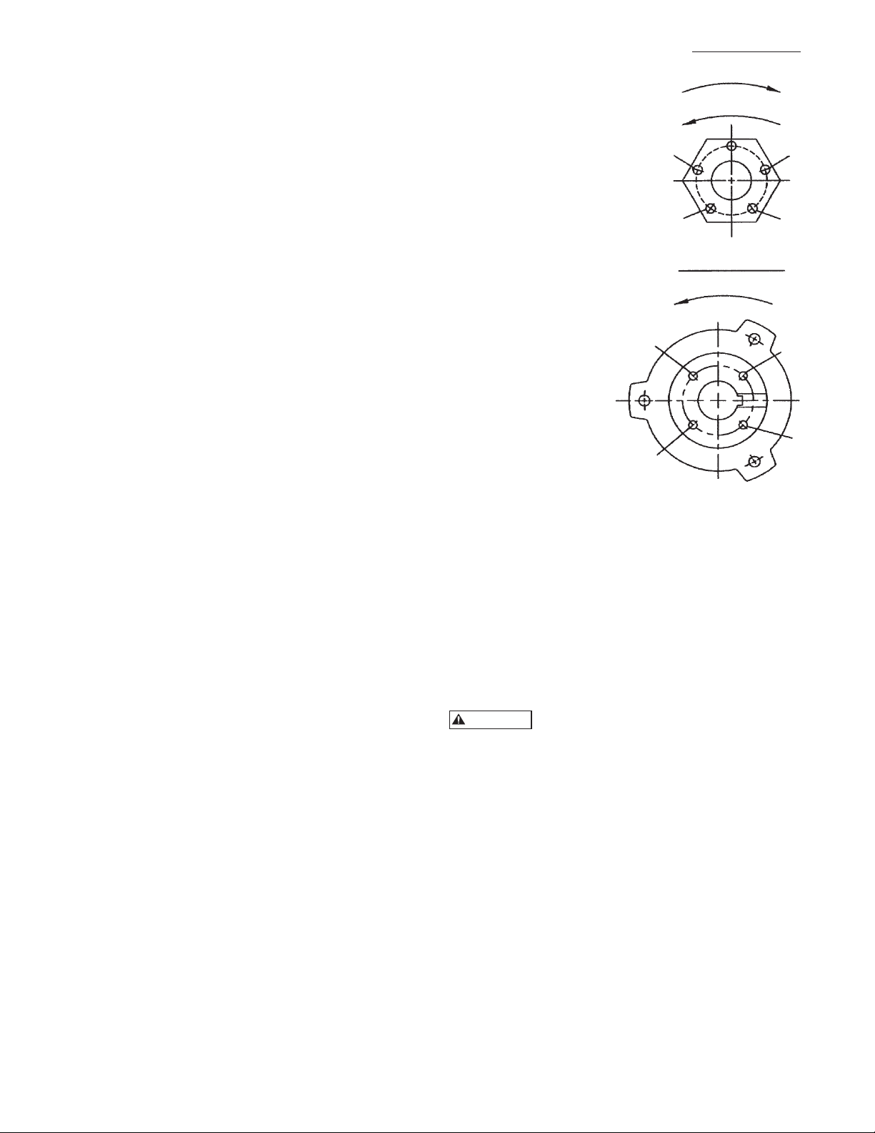
IMPELLER ADJUSTMENT FOR ALL
HOLLOW SHAFT DRIVERS
NOTE: Shaft adjustment up or down is accomplished by
turning the adjusting nut (604) Figure 13.
NOTE: There are five holes in the adjusting nut and
only four in the motor coupling. See Figure 13.
1. With shafting all the way down and the impellers
resting on their seats, turn the adjusting nut (604)
in counter-clockwise direction, thus lifting the shaft,
until the impellers just clear their seats and the
shaft/motor turns free by hand. This removes all
deflection from the shaft.
2. If pump setting is 200 ft. or less, make another two
turns on the adjusting nut for the first 100 ft. (3
turns for 12 thread/inch shaft). Line-up one of the
holes in the adjusting nut with the nearest hole in
the driver coupling. Insert the capscrew in the hole
and tighten it.
NOTE: 1.00" and 1.18" diameter shafts are 12 thread
per inch (tpi), 1.50" through 2.44" are 10 tpi, all
larger sizes are 8 tpi.
3. For pump setting over 200 ft. see IOM for DWT.
FOR OPEN IMPELLERS
1. With shafting all the way down and the impellers
resting on their seats, turn the adjusting nut (604)
in counter-clockwise direction, thus lifting the shaft,
until the impellers just clear their seats and the
shaft/motor turns free by hand. This removes all
deflection from the shaft.
2. Align hole “A” in the
(604) ADJUSTING NUT
adjusting nut (604) and
hole “C” in the driver
LOWER IMPELLER
coupling (See Figure13) or
whatever similar holes are
RAISE IMPELLER
in like position. If care is
exercised, this will give an
initial impeller clearance
A
of 0.001” to 0.003”
depending on shaft size or
the pitch of the thread.
3. Insert capscrew into hole
B
E
“B” provided these are the
nearest matching holes
for counter-clockwise
rotation of adjusting nut,
MOTOR COUPLING
ROTATION
turn adjusting nut counterclockwise until holes “B”
and “D” line up. This
gives 1/20 of a turn
C
H
which is 0.004”
on 12 tpi shaft or
0.005” on 10 tpi
shaft.
4. Normal impeller
clearance for the
open impeller is
D
consider to be 0.015”
for the first 10 ft of
the column length and
Figure 13
0.010” additional clearance for each 10 ft of length
thereafter. This can be reduced in some instances
where is necessary, but should not be attempted
without consulting the factory or factory serviceman
if present.
INSTALLATION OF A SOLID SHAFT DRIVER
NOTE: When pump is supplied with an oil lubricated
thrust pot, do not secure driver to discharge
head until after the thrust pot and flexible
coupling are installed. (See page 22 for thrust
pot installation instruction.)
Do not work under a heavy suspended
object unless there is a positive support
and safe guard which will protect personnel should a
hoist or sling fail.
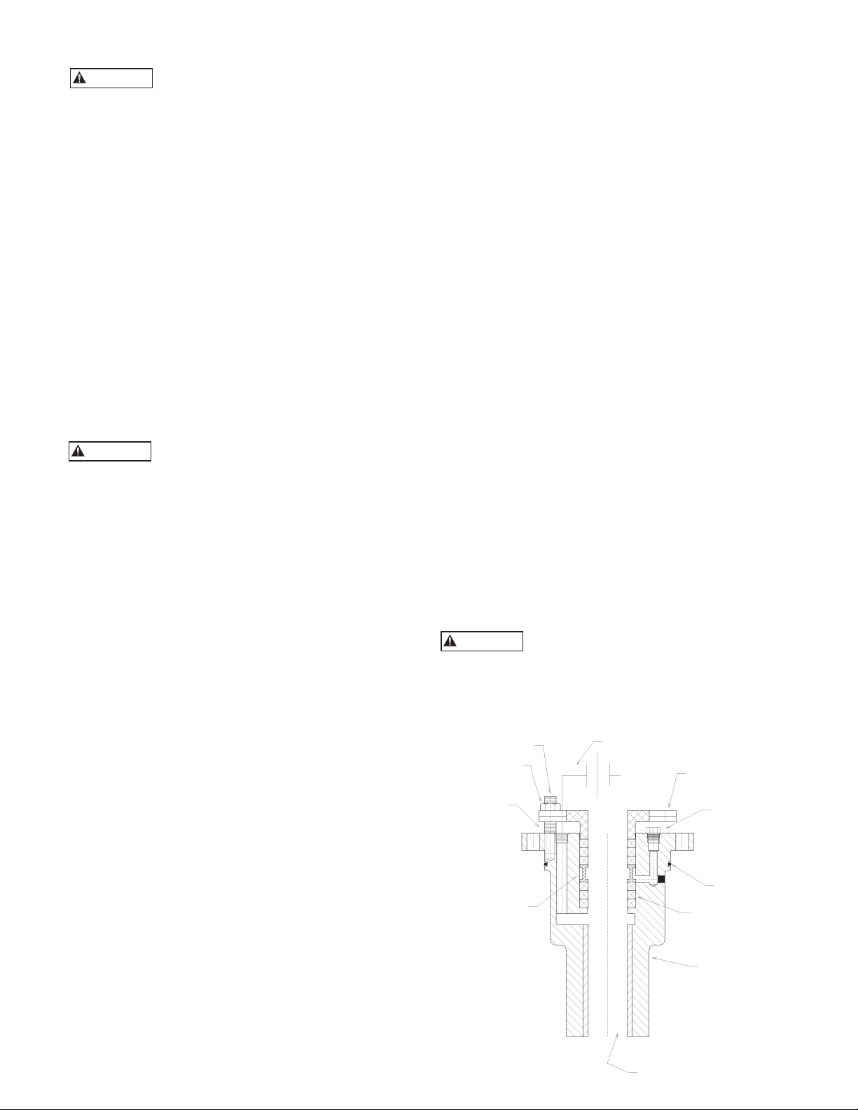
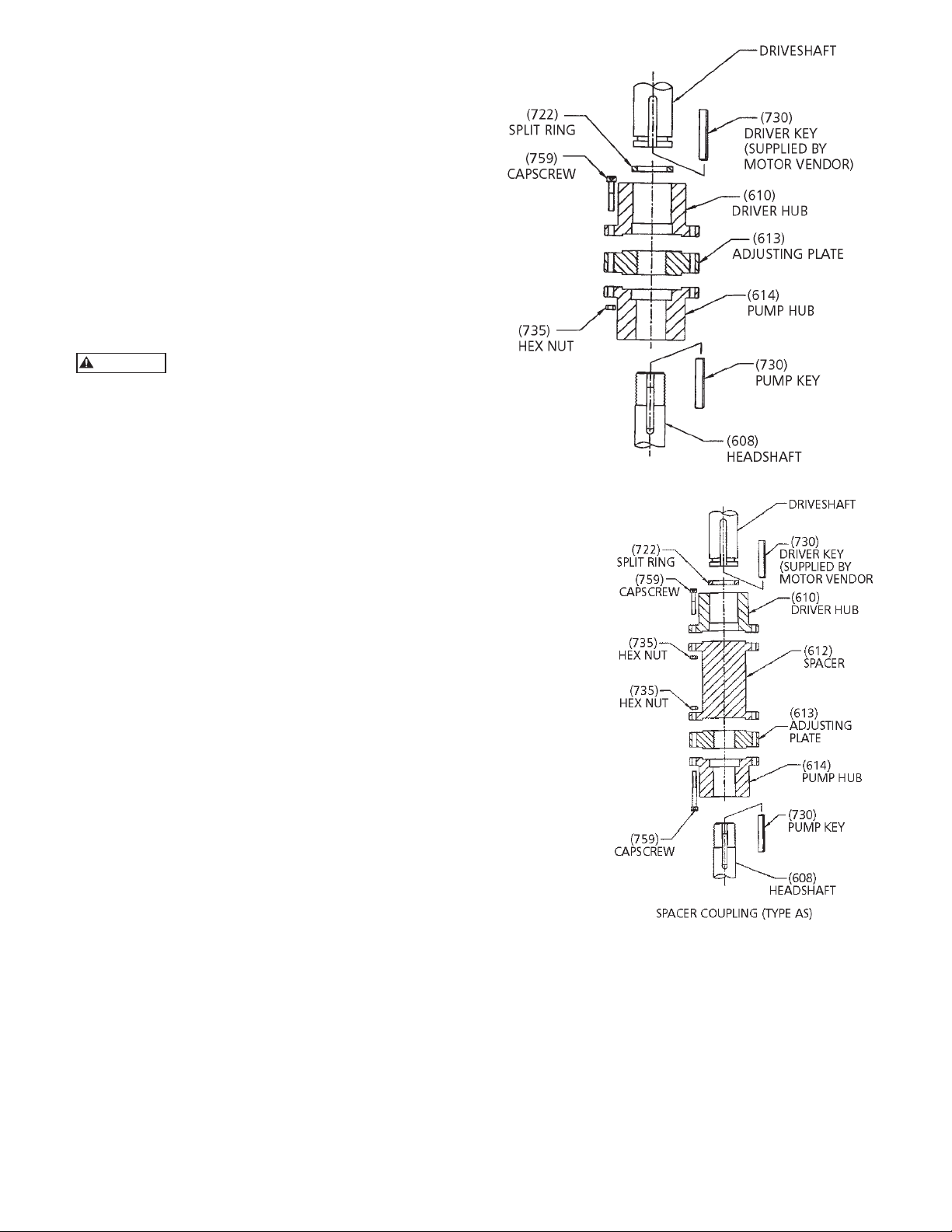
The coupling between the driveshaft and discharge head
shaft may be a non-spacer type (see Figure 14), or a
spacer type (see Figure 15). The latter is used on pumps
furnished with a mechanical seal to permit servicing of
the seal without removal of the driver.
1. Driver support. When a driver support is furnished
and not installed, proceed as follows.
A. Hoist driver support, inspect the mounting
surfaces, register and clean these surfaces
thoroughly.
B. Install driver support on discharge head and
secure with capscrews provided.
2. Attach a sling to the lifting lugs of driver, hoist
motor, inspect the mounting surface, register, and
shaft extension, and clean those surfaces thoroughly.
If any burrs are found, remove burrs with a smooth
mill file, cleaning thoroughly afterward.
F
G
20
Page 21
3. Orient the motor conduit box in the required
WARNING
position. Align the motor mounting holes with the
mating tapped holes on the discharge head. Lower
the motor until the registers engage and the motor
rests on the discharge head. Secure motor with
capscrews provided.
4. On drivers having a non-reverse ratchet or pins,
manually turn the driver shaft clockwise viewed
from the top until the non-reverse ratchet or pins
fully engage.
5. Lubricate motor bearings in accordance with
instructions given on lubrication plate attached to
the motor case.
NOTE: Please read and follow the motor manufacturer’s
instructions before lubricating the motor
bearings. Too much lubricant can cause the
bearings to overheat and prematurely fail.
The motor must not be tested for direction
of rotation when coupled to the pump.
If pump should rotate in the wrong direction, serious
damage to the pump and motor would result. Also
serious injury to personnel could result.
6. Make temporary electrical connections according
to tagged leads or diagram attached to the motor.
Motor must rotate counter-clockwise when viewed
from the top. See arrow on pump name plate. If
motor does not rotate counter-clockwise, you can
change the rotation by interchanging any two leads
(For three phase only, for single phase motors see
motor manufacturer’s instructions.)
7. Motor shaft end play adjustment: if required,
motor shaft end play shall be checked with a dial
indicator prior to connecting the pump coupling to
the solid shaft motor. Consult the applicable motor
manufacturer’s instruction manual for detailed
information on motor shaft end play.
COUPLING INSTALLATION: (SEE FIGURES 14 and 15)
1. Check all mating face with a fine flat file before
installation. Remove all burrs from face.
2. Apply a thin film of oil on the pump key (730) and
insert key into headshaft keyway seat.
3. Gently lower pump hub of coupling (614) onto
headshaft.
4. Thread on the adjusting plate (613) onto the
headshaft until flush with top of the headshaft.
5. Clean driver shaft by removing all grease and burrs.
Try to fit the key on the driver hub (610) before
installing it to the driver shaft.
Figure 14
Figure 15
6. Apply a thin film of oil to the driver key (730) and
insert key into drive shaft keyway seat. Place the
driver hub (610) onto the drive shaft and with key
slide it up the drive shaft until the annular grove is
exposed. Install split ring (722) in the groove and
slide driver hub down over the split ring to capture it.
7. If the pump is supplied with an adjustable spacer
coupling (see Figure 15), install spacer (612) between
headshaft and driveshaft hubs. Secure with capscrews
(759) and hex nuts (735).
21
Page 22
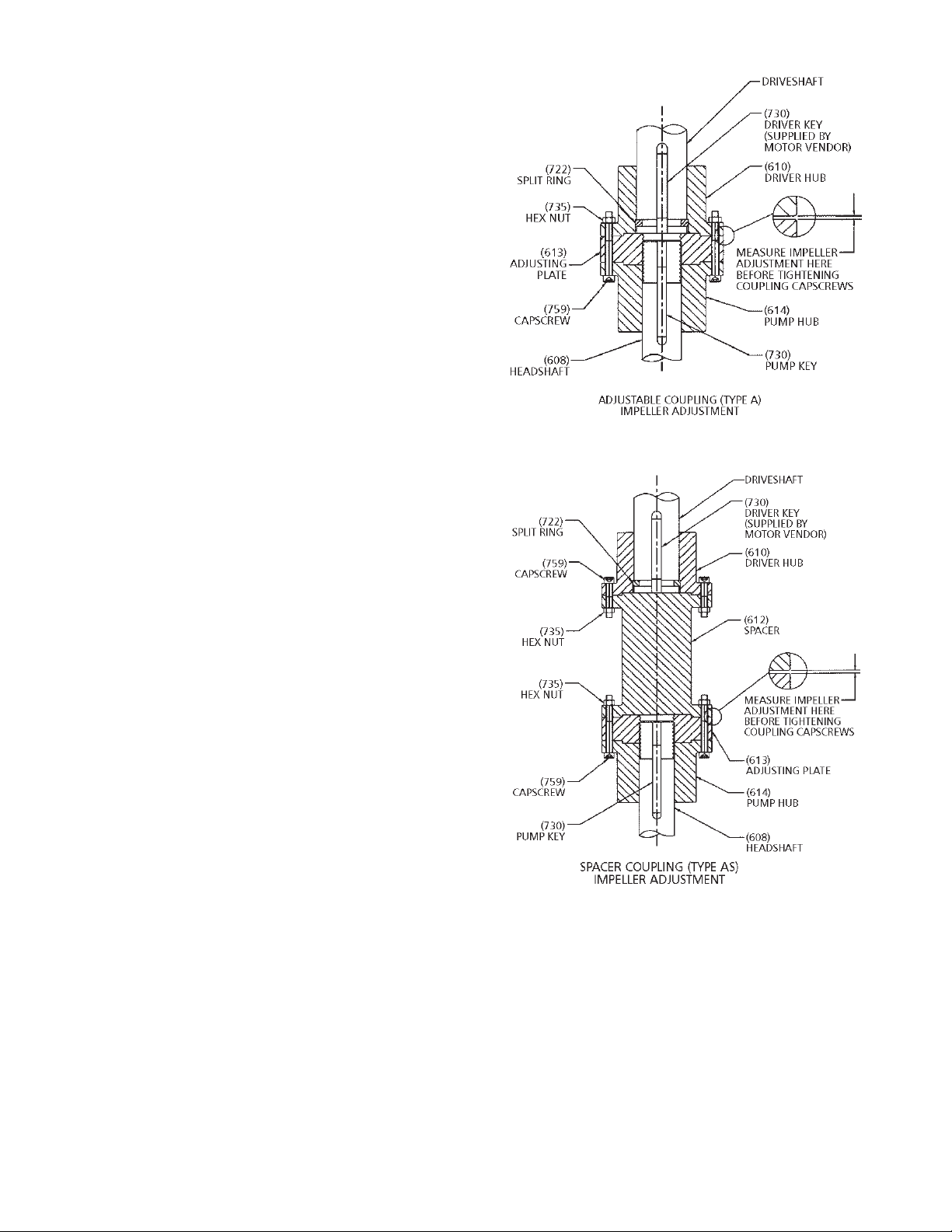
IMPELLER ADJUSTMENT
Impeller adjustment is identical for all motors and right
angle gear drives. Adjustment is accomplished by turning
the adjusting plate (613). (See Figure 16 or 17). The
correct adjustment is listed on the Outline Drawing for
the specific unit. If the pump has a thrust pot, do not
adjust the impeller position until the thrust pot has been
installed and adjust the impeller position by using the
adjust nut on the thrust pot.
NOTE: Mechanical seal, when provided, must not be
secured to the shaft prior to impeller adjustment.
(open or enclosed type impellers). Shaft must
move up or down within the seal Assembly.
For pumps handing liquids between –50º to
200º F, impeller adjustment can be made under
ambient conditions. For liquids in excess of
this range, it is recommended that impeller
adjustment be made after the pump surface
temperature has reached an equilibrium when
charged with the pumpage. In those cases, where
this is not feasible due to safety consideration
or impossible due to external ice build up in
cryogenic applications, refer to factory for
specific instructions.
NOTE: When impellers are reset, the seal must also be
reset.
Figure 16
OPEN IMPELLERS
1. With the impellers touching the bottom of the
bowls, turn the adjusting plate (613) towards the
driver hub (610) or spacer (612) to obtain 0.015
inch clearance between the adjusting plate and
driver hub or spacer for the first 10 feet of column.
Add 0.010” for each additional 10 feet of column.
See Figures 16 and 17. Note: The determination of
driver shaft end play can be critical and should be
added to this setting. For larger pumps over 8”, this
amount may be too little; please refer to Outline
Drawing.
Example: total pump length is 50 feet - set impellers
at 0.055 inch.
2. After impeller adjustment, align adjusting plate (613)
with the pump hub (614), and tightly draw coupling
flanges together with capscrews (759) and nuts
(735). (See Figures 14 and 15.)
3. Check shaft run out with dial indicator. For
mechanical seal installation, the run out should be
0.005" or less.
4. Set seal after impeller adjustment. Securely tighten
all set screws in the collar. Remove the spacer
between the gland plate and collar. Retain spacer for
future resetting of seal.
Figure 17
ENCLOSED IMPELLERS
For enclosed impellers obtain the clearance between the
adjusting plate and driver hub or spacer as specified on
the outline drawing. See Figure 16 or 17.
22
INSTALLING THE GREASE LUBRICATED THRUST POT
This type of thrust pot and the motor stand are
assembled on the discharge head by the factory. This
thrust pot is designed to be used with NEMA Vertical
C-face motors. The motor shaft and the pump shaft are
to be coupled with flexible coupling.
Page 23

INSTALLATION:
WARNING
1. Install both coupling halves prior to mounting
the motor. Refer to the coupling manufacturer’s
instructions.
2. Using the lifting lugs on the motor, carefully lower
the motor onto to the motor stand of the thrust pot
(See Figure 18) and align the bolt holes.
3. Install the bolts finger tight.
4. Make temporary electrical connections according
to tagged leads or diagram attached to the motor.
Motor must rotate counterclockwise when viewed
from the top. See arrow on pump name plate. If
motor does not rotate counterclockwise, you can
change the rotation by interchanging any two leads.
Before beginning any alignment
procedure, make sure driver power is
locked out. Failure to lock out driver power will result
in serious physical injury.
ALIGNMENT OF FLEXIBLE COUPLING:
Alignment of the pump and motor is extreme importance
for trouble-free mechanical operation. Straight edge
alignment by an experienced installer proves adequate
for most installations.
1. Check for coupling alignment by laying a straight
edge across both coupling rims at four points 90º
apart.
2. Move motor until straight edge rests evenly at each
position. Repeat procedure until correct alignment
is achieved.
3. Install flexible sleeve between the hubs per the
manufacture’s instructions.
4. Tighten all motor bolts.
NOTE: Be sure the relief fitting (#11 in Figure 18) is
clear of paint or any other obstructive material.
Otherwise it will cause premature failure of the
thrust pot and is not covered under warranty.
INSTALLING THE OIL LUBRICATED THRUST POT
If the unit is supplied with a thrust pot (see Figure 19),
the thrust pot should be installed on top of the discharge
head or motor stand before installing the driver. The
driving mechanism of the thrust pot assembly is similar to
the hollow shaft motor. (See Figure 12)
1. Attach a sling to the thrust pot assembly through
the windows on the motor adapter and hoist the
assembly over the top of the discharge head.
2. Clean the mounting face with a flat file to remove
any burrs of the discharge head and the thrust pot.
Lower the thrust pot assembly and orient it so that
the bolt hole on the base of the thrust pot and the
top flange of the discharge head are line up. Install
all the bolts to secure the assembly to the discharge
head.
3. Lower the drive shaft through the quill of the thrust
pot assembly to meet the shaft coupling. Apply a
thin film of oil to the head shaft thread and screw
into the shaft coupling.
4. For unit with mechanical seal and flanged coupling,
install the spacer flange coupling as instructed on
page 20.
5. Install the gib key (#16) into the drive shaft and the
hollow shaft clutch.
6. Install the adjusting nut (#17) to hand tight.
7. With shafting all the way down and the impellers
resting on their seats, turn the adjusting nut (#17)
in counter-clockwise direction, thus lifting the shaft,
until the impellers just clear their seats and the
shaft/motor turns free by hand. This removes all
deflection from the shaft.
8. For enclosed impellers, if pump setting is 200 feet
or less, make another two turns on the adjusting
nut for the first 100 feet (3 turns for 12 tpi shaft)
Line-up one of the holes in the adjusting nut with
the nearest hole in the driver coupling. Insert the
capscrew in the hole and tighten it.
Figure 18 – Grease Lubricated Thrust Pot
NOTE: 1.00" and 1.18" diameter shafts are 12 tpi, 1.50"
through 2.44" are 10 tpi, all larger sizes are 8 tpi.
ITEM DESCRIPTION
1 Motor stand
2 Head shaft
3 Bearing housing
4 Bearings
5 Top seal
6 Snap ring
7 Lock nut
8 Lock washer
9 Lower seal
10 Grease lube fitting
11 Grease relief fitting
12 Hex tap bolt
13 Hex nut
14 Hex capscrew
23
Page 24

9. Install the bottom of the flexible coupling to the top
WARNING
of the drive shaft.
10. Attach a sling to the lifting lugs of driver and hoist
the driver up. Inspect the mounting surface, register
and clean these surfaces thoroughly. If any burrs
are found, remove burrs with a smooth mill file,
cleaning thoroughly afterward. Temporarily attach
the top half of the flexible coupling to the motor
shaft.
11. Orient the motor conduit box in the required
position. Align the driver mounting holes with
the mating tapped holes on the discharge
head. Lower the driver until the registers
engage and the driver rests on the thrust
pot assembly. Secure driver with capscrews
provided.
12. Secure the flexible coupling assembly.
13. Install the coupling guard.
14. Fill the oil reservoir with recommended oil.
Pump Startup And Operation – SECTION 4
PRE-START PROCEDURE
Consult the applicable manufacturer’s instructions
for detailed information for the prime mover
(electric motor, engine or steam turbine), coupling,
driveshaft, gear driver. Prior to startup, check the
following:
1. Confirm that the following procedures
described in the “Installing the Drivers”
sections have been performed:
A. Wiring of Driver.
B. Driver must rotate counterclockwise
(CCW) when viewed from above.
Do not check motor rotation unless motor
is bolted to pump and drive coupling is
removed.
Be sure to remove all the hand tools and to install the
coupling guards around all exposed shafts and couplings
before start up of the pump. Failure to comply may
result in sever personnel injury or death.
C. Check alignment of pump and driver.
D. Impeller adjustment has been made.
E. Mechanical seal lock collar is attached to shaft.
Figure 19 – Oil Lubricated Thrust Pot
ITEM DESCRIPTION
1 Thrust pot body
2 Tube - oil retaining
3 Thrust bearing
4 Capscrew - head to thrust pot
5 Washer - head to thrust pot
6 Hex Nut - head to thrust pot
7 Roller bearing
8 Bearing seat
9 Allen head screw
10 Capscrew - motor adapter to motor or thrust pot
11 Washer - motor adapter to motor or thrust pot
12 Gasket
13 Capcsrew
14 Non-reverse pin
15 Socket head screw
16 Gib key
17 Adjusting nut
18 Coupling guard
19 Setscrew
ITEM DESCRIPTION
20 Flexible shaft coupling
21 Gib key
22 Key (motor shaft)
23 Setscrew
24 Round head screw for coupling guard
25 Washer coupling guard
26 Motor adapter
27 Capscrew - adjusting nut
28 Washer - adjusting nut
29 Retaining ring
30 Hollow shaft clutch
31 Non-reverse plate
32 Pipe plug - oil filling
33 Retaining ring
34 Hollow shaft
35 Shaft sleeve
36 Sight gauge
37 Pipe plug - oil drain
24
Page 25

2. For open lineshaft pump, make sure the stuffing
box relief (bleed) line is connected (if applicable).
For enclosed lineshaft pump, make sure the oil
lubrication piping is connected and oil reservoir
filled with the recommended oil. (See page 15 and
18.)
3. For pump with mechanical seal, make sure
mechanical seal is properly lubricated and all
piping to seal is connected. Also, check that all
cooling, heating and flushing lines are operating and
regulated.
4. For open lineshaft pump, when water level
exceeding 30 feet, pre-lubrication is necessary. If
it is equipped with prelube system supplied from a
pressurized header, open the supply valve and allow
the prelube water to flow for 15 seconds plus 15
seconds per 100 ft of pump setting. If it is equipped
with a tank type prelube system, open the valve
between the prelube tank and the pump and allow
approximately half of the water in the tank to run
into the pump before start the pump. The prelube
valve should remain open during the start up.
5. For oil lubricated pump, clean and fill the
lubricator tank with recommended oil. (See page
27.) Manually open the lubricator valve and allow
oil to run into the shaft enclosing tube for at least
20 minutes for each 100 feet of setting prior to
start up. On the system equipped with a solenoid
operated lubricator valve that cannot be energized
independently, it will be necessary to remove the
valve stem to allow the oil to flow into the tube. If
the start up is delayed or the pump has been shut
down for over 150 hours, the lubrication procedure
must be repeated just prior to actual start up.
6. Open the air release system isolation valve.
Adjusting the air release system throttling device so
that it is partially open. It should not be closed or
fully open.
NOTE: Not exhausting the air or exhausting it too fast
can damage the pump.
7. All connections to driver and starting device match
wiring diagram. Voltage, phase and frequency on
motor nameplate agree with line current.
PUMP STARTUP
1. Partially close the valve in the discharge line.
2. Start the pump. If any abnormal noises, jerking
or vibration is noted, stop the pump immediately,
determine the cause of the abnormalities and correct
them.
3. After the pump is operating at full speed, slowly
open discharge valve. If driver overheats or there is
excessive vibration, stop the pump, determine the
causes and correct them.
4. If the air release valve is manually operated, close it.
5. For open lineshaft pumps, with the pump in
operation, there should be some leakage at the
stuffing box packing. The correct leakage rate is
approximately one drop per second. Check the
temperature of the leakage as well as the discharge
head. If the pump runs hot and the leakage begins
to choke off, stop the pump and allow it to cool
down. A few light taps with a hammer on the gland
will upset the packing sufficiently to resume leakage.
After pump has cooled, restart pump and follow
preceding procedure. Run pump 15 minutes, check
leakage, if it exceeds two drops per second, adjust
packing as described in “Packing Adjustment and
Replacement”.
6. For enclosed line shaft pumps, adjust the lubricator
valve for the proper flow rate of the lubrication oil.
(See Page 18.)
7. For pump with mechanical seal, if seal leaks slightly
at startup, allow a reasonable amount of time for
seal to adjust itself. Liquids with good lubricating
qualities normally take longer to wear in the seal
than liquid with lesser qualities. When a seal starts
out with a slight leak and gets progressively less
while running, it is indicative of leakage across the
seal faces. Continued running will eliminate this.
Where leakage occurs immediately and remains
constant, unaffected by running, it usually indicates
secondary seal (Shaft packing) damage, or seal faces
are warped out of flat.
8. Rotate shaft manually to ensure impellers are not
binding.
9. Verify that driver bearings are properly lubricated
and check oil level in housing.
10. Inspect discharge piping connection, valves and
pressure gauges for proper operation.
25
Page 26

Maintenance – SECTION 5
CAUTION
WARNING
WARNING
WARNING
PREVENTIVE MAINTENANCE
Before initiating maintenance procedures,
disconnect all electric sources to the
equipment and accessories and completely. Discharge
all parts and accessories which retain electric charges.
Failure to comply may result in severe personnel injury
or death.
Preventive maintenance includes periodic inspection
of oil level in the oil reservoir (for pump with oil lube
column) re-lubrication of electric motors, gear drives
and prime mover. Systematic inspection of the pump
and its components shall be made at regular intervals.
The frequency required depends upon the operating
conditions of the pump and its environment. See
following Preventive Maintenance schedule. Consult
the applicable manufacturer’s instructions for detailed
information on maintenance for the prime mover,
driveshaft, electric motors and gear drives. Any deviation
in performance or operations from what is expected can
be traced to some specific cause. Variances from initial
performance will indicate changing system conditions,
wear, or impending breakdown of the unit.
PREVENTIVE MAINTENANCE SCHEDULE
(in operating hours)
Clean dirt, oil and grease from
driver and discharge head.
Clean driver ventilation passage to
prevent overheating.
Change lubrication in gear drive. 2,000 or once a year
Change lubrication in thrust pot. See page 27
Check oil level in the reservoir.
It should never be less than ½ full. 24
Refill, check drip rate.
Tighten all loose bolts and check
for excessive vibration.
If packing is grease lubricated,
add as required.
Check that there is some leakage
through stuffing box while pump is
in operation. Do not tighten gland As required
nuts unless necessary. Refer to
page 24 for tightening requirement.
Maintain a liquid film of lubrication
between the seal rubbing faces.
Re-grease the motor bearings:
1800 RPM and above Refer to Motor IOM
Below 1800 RPM Refer to Motor IOM
PROCEDURE
TIME INTERVAL
As required
As required
As required
100
As required
It may be necessary to repeat this procedure several
times before proper amount of liquid comes through to
efficiently prevent overheating. If leakage is excessive,
adjust the stuffing box as follows:
1. With the pump in operation, tighten the gland nuts
one-quarter turn for each adjustment. Allow packing
to equalize against the increased pressure and
leakage to gradually decrease to a steady rate, before
making another adjustment.
Do not over tighten the stuffing box.
Excessive pressure can wear out packing
prematurely and seriously damage the shaft.
2. With the pump shut down and when packing has
been compressed to the point that the gland is about
to contact the upper face of stuffing box, remove
the split gland, add one extra packing ring and
readjust. If this fails to reduce leakage to two drops
per second, remove all packing rings and replace
with new rings.
3. Remove the packing with the aid of a packing hook.
If a lantern ring is provided, remove it by inserting
a wire hook in the slots of the ring and pull it from
the packing box. Thoroughly clean the stuffing box
of all foreign matter.
4. If the replacement packing is in the form of a
continuous coil or rope, it must be cut into rings
before installing. Tightly wrap one end of the
packing material around the top shaft like one coil
spring, and cut through the coil with a sharp knife.
For re-packing sequence, refer to “Installing the
Stuffing Box” (page 15).
Do not over tighten the stuffing box.
Excessive pressure can wear out packing
prematurely and seriously damage the shaft.
SEASONAL SHUTDOWN
Prior to restarting the pump, manually
rotate the shaft several times.
1. For oil lubricated pumps that are shut down for
an extended period of time, it is suggested that the
pump be operated for at least 15 minutes every two
weeks with oil feed wide open 2 hours before and
during startup in order to maintain a film of oil on
the shafting and shaft bearings.
2. For product (or water) lubricated pump, if the pump
is to be shut down for an extended period of time,
operate it for at least 15 minutes with adequate prelubrication every two weeks.
PACKING ADJUSTMENT AND REPLACEMENT
Pumps equipped with packing, shall be adjusted
whenever the leakage rate exceeds two drops per second.
If there is no leakage or the stuffing box overheats, do
not back off gland nuts while the pump is running. This
will allow the entire set of rings to move away from the
bottom of the box, without relieving pressure of the
packing on the shaft. Stop the pump and allow packing to
cool then restart the pump.
26
3. Before resuming normal operations, oil should be
changed on drivers, right angle gear and lubricating
oil system. After 15 minutes of operation adjust the
lateral.
Page 27

WARNING
WARNING
THRUST POT LUBRICATION AND MAINTENANCE
OIL LUBRICATED THRUST POT (SEE FIGURE 19)
Pumps are shipped without oil. Oillubricated bearings must be lubricated at
jobsite.
The bearing is pre-lubricated at factory. Re-grease the
bearing according the following procedure and per the
schedule in the above table. Following are the re-grease
procedure:
1. Wipe dirt from grease fittings.
It is a good practice to flush the oil reservoir before
first time operation and at the time of oil changes to
remove all grit particles in the oil reservoir sump. Use
the same type of oil to flush reservoir as specified for
lubrication. (See page 28 on recommended turbine oil.)
Remove drain plug (Item # 39) before flushing. Flushing
oil may be poured through oil fill opening (item #33)
after removing oil fill plug #39. The proper oil level
when the unit is not running shall be not more than 1/8”
to ¼” from the top of the oil sight gauge (Item #37).
Overfilling may result in overheating of the unit. During
operation the oil level in the sight gauge may be higher
than the recommended range mentioned above. Under
no circumstance is it allowed to rotate the unit when the
oil in the sight gauge is not at the required level.
To avoid oxidation of the anti-friction bearings during
shut-down periods lasting longer than one week, it is
recommended to fill up the oil reservoir until the oil runs
over the oil retainer tube (Item #2) and down the shaft
so that the bearings remain completely immersed in the
oil. Before startup, do not forget to drain the excess oil
to its required level. Oil change depends on the severity
of the environment. Generally speaking, when the oil
in the sight gauge changes to a darkish brown color it
is time for an oil change. However, for a longer bearing
life, it is recommended that the oil be changes every six
months. Be sure to flush the oil reservoir (see above)
with each oil change.
GREASE LUBRICATED THRUST POT (SEE FIGURE 18)
Lubricating Intervals in Operating Hours
2000 lbs 2000 2000 2000 1800
4000 lbs 2000 2000 1600 1400
6600 lbs 2000 2000 1400 1200
Operating Speed (RPM)
Thrust
Rating
<1770 1770 2900 3500
2. Check relief port 180º from fitting to make sure it is
open.
3. Fill the grease cavity through the fitting until fresh
grease comes out the relief hole.
4. Ensure the relief port closes.
NOTE: The bearing temperature usually rises after
re-greasing due to an excess supply of grease.
Temperature will return to normal after the
pump has run and purged the excess from the
bearings, usually two to four hours.
For most operating conditions, lithium based NLGI 2
grease is recommended. This is the grease factory used
for pre-lubrication. This grease is acceptable for bearing
temperatures of 5º to 230º F. Temperature extremes
(either high or low) may require different type grease.
Following table lists some various manufacturers’
compatible grease:
Mobil Mobilith AW2
Amoco Amolith EP2
Ashland Multilube EP2
Exxon Unirex N2
Shell Alvania EP LF2
Unocal Unoba EP2
Chevron Dura-Lith EP NLGI2
NOTE: If it is necessary to change the grease type or
consistency, the bearing must be removed and all
the old grease eliminated from the housing and
bearing.
Bearings must be lubricated properly in
order to prevent excess heat generation,
spark and premature failure.
27
Page 28

RECOMMENDED LUBRICANTS
Grease for Lineshafts, Turbine oils for Lineshafts,
Suction Bowl Bearings Suction Bowl Bearings
and Shaft Packings and similar applications
Operating Temperature Range 20º F to 120º F 20º F to 120º F
Required properties
Pour Point : 20º F or lower (base oil) 20º F or lower
Flash Point : 300º F or higher (base oil) 300º F or higher
100º F Viscosity : 450 SUS or higher (base oil) 150 SUS or higher
ASTM Dropping Point : 160º F or higher 32
Nitrile Rubber Swell : Minimal (up to 3%) Minimal (up to 3%)
Thickener Type: Calcium or Lithium
Thickener Percent: 15% Minimum
Manufacturer Recommended Standard Industrial Lubricants
Chevron Chevron
Texaco Texaco
Chevron Texaco Corp.
Novatex EP2 *Regal EP 32
Mystik Oil & Grease Mystik Oil & Grease
Mystik JT-6 Grease (5484) *Mystik Turbax Oil 32 (1812)
Premium Lithium EP2 Pacemaker Oil 32
CITGO Petroleum Corp.
Lyondell Lubricants Lyondell Lubricants
Litholine HEP Grease *Duro Oil 32
Mobil Mobil
Exxon Exxon
Exxon Mobil Corp.
Lodok EP 2 *Nuto H Hydraulic Oil 32
Multiplex EP Grease 2 Hydraulic Oil AW/D 32
Alvania EP Grease 2 *Tellus Plus Oil 32
Note: * in front of the oil grade means it is suitable for sub zero (F) temperature service.
76 Lubricants Co.
Shell Oil
Shell Shell
Ulti-Plex Grease EP2 *Hydraulic Oil AW32
Citgo Oil & Grease Citgo Oil & Grease
Mobilux Grease EP2 DTE Oil 24
76 Lubricants 76 Lubricants
Manufacturer Recommended Food Machinery Lubricants
Chevron Chevron
Texaco Texaco
Chevron Texaco Corp.
#Cygnus Grease 2 #Cygnus Hydraulic Oil 32
Mystik Oil & Grease Mystik Oil & Grease
#Mystik FG2 Grease (5607) #Mystik FG/AW 32 Oil (1931)
#Clarion FG HTEP Grease #Clarion FG AW Oil 32
CITGO Petroleum Corp.
Lyondell Lubricants Lyondell Lubricants
Ideal FG 2 Grease #Ideal FG 32 Oil
Mobil Mobil
Exxon Exxon
Exxon Mobil Corp.
Foodrex FG 1 *Nuto FG Hydraulic oil 32
76 Pure FM Grease 76 FM Oil 32
Note: 1. * in front of the oil grade means it is suitable for sub zero temperature (F) service.
2. Food machinery lubricants meet USDA H-1 requirements and FDA document 21 CFR 178.3570.
In addition, # in front of the product name means it is NSF 61 registered products.
76 Lubricants Co.
#FM Grease EP2 *#Lubricating Oil FM32
Citgo Oil & Grease Citgo Oil & Grease
#Mobil Grease FM102 DTE FM 32 Oil
76 Lubricants 76 Lubricants
28
Page 29

TROUBLESHOOTING
TROUBLE PROBABLE CAUSE REMEDY
1. Pump does not start A. Electrical circuit open or not Check circuit and correct.
completed
B. Improper lateral adjustment. Reset impeller adjustment,
Impeller on bottom. See pages 20 or 22.
C. Low voltage supplied to Check whether driver wiring is
electric driver correct and receiving full voltage.
D. Defective motor Consult factory.
2. No liquid delivered A. Discharge valve closed Be sure the discharge valve is in
full open position.
B. Speed is too low Check if driver is directly across
the line and receiving full voltage.
C. Wrong rotation Check for CCW rotation when
viewed from above. Check
engagement of motor coupling.
D. Obstruction in liquid passage Pull pump, inspect suction
strainer, impeller and bowls.
E. Water level in the well is below Increase pump setting by adding
1st stage impeller column.
F. Static lift too high Check the dynamic water level in
well. Consult factory for adding
stages or increase impeller diameter.
G. Field head requirement greater Check system friction loss.
than design head Increase discharge piping size.
Consult factory for adding stages
or increase impeller diameter
H. Damaged bowl assembly; Pull pump and repair all
Broken or disconnected shaft damaged components.
I. Driver with reduced voltage, or Check RPM, voltage and amps.
reduced current starting does
not come up to speed
3. Not enough liquid A. Same as items 2-A thru 2-G Same as items 2-A thru 2-G.
B. Cavitation Insufficient NPSH available.
Consider lowering the bowl
assembly by adding column.
C. Impellers adjusted too high See pages 20 or 22.
D. Air or gas in the water If successive starts and stops
do not remedy, lower pump if
possible, or close discharge
valve to maintain well pumping
level at a lower GPM.
E. Excessive pump wear Pull pump and repair as required.
4. Not enough pressure See not enough liquid. See not enough liquid.
5. Pump works for a while A. Excessive horsepower required. Use larger driver. Consult factory.
and quits B. Pumping higher viscosity or Test liquid for viscosity and
specific gravity liquid than specific gravity.
designed for.
C. Mechanical failure of Check bearings and impellers for
critical parts damage. Any irregularities in
these parts will cause a drag
on the shaft.
D. Suction strainer clogged Pull pump and clean the strainer.
E. Misalignment Realign pump and driver.
F. Break suction Check dynamic water level in the
well. Lower bowl assembly by
adding column.
29
Page 30

TROUBLESHOOTING
TROUBLE PROBABLE CAUSE REMEDY
6. Pump takes too much A. Damaged impeller Inspect, replace if damaged.
power B. Foreign object lodged between Remove object as required.
impeller and bowl
C. Specific gravity higher than Test liquid for viscosity and
pump designed for specific gravity.
D. Viscosity too high, partial Check for both. They can cause
freezing of pumpage drag on impeller.
E. Defective bearing Replace bearing, check shaft or
shaft sleeve for scoring.
F. Packing is too tight Release gland pressure.
Retighten. (See page 15.) Keep
leakage flowing. If no leakage,
check packing, sleeve or shaft.
7. Pump is too noisy A. Cavitation Same as Item 3-B.
B. Bent shaft Straighten as required. See
Page 13 for runout limits.
C. Rotating parts binding, loose Replace as required.
or broken.
D. Bearings are worn out Replace bearings.
E. Resonance Check piping strain, consult factory.
8. Excessive vibrations A. Coupling misalignment, bent Determine cause utilizing shaft
impeller unbalance, worn vibration frequency analyzer
bearings, cavitation, piping and/or disassemble pump.
strain and/or resonance Complex problem may require
factory service assistance.
B. Motor or gear driveshaft end See Installation of Hollow Shaft
play maladjustment Driver (VHS), Page 19.
C. Bent shaft Straighten as required. See
Page 13 for runout limits.
D. Crooked well. Survey the well and consult factory.
9. Pump leaks excessively A. Defective packing Replace worn packing.
at stuffing box B. Wrong type of packing Replace packing not properly
installed or run-in. Replace
improper packing with correct
grade for liquid being pumped.
10. Stuffing box is A. Packing is too tight See item 6-F.
overheating B. Packing is not lubricated Release gland pressure and
replace all packing if burnt or
damaged. Re-grease packing
as required.
C. Wrong grade of packing Consult factory.
D. Stuffing box improperly packed Repack stuffing box.
11. Packing wears too fast A. Shaft or shaft sleeve worn Pull pump and remachine, or
replace shaft and/or sleeve.
B. Insufficient or no lubrication Repack and make sure packing
is loose enough to allow some
leakage.
C. Improperly packed Repack properly, make sure all
old packing is removed and
stuffing box is clean.
D. Wrong grade of packing Consult factory.
30
Page 31

Disassembly And Reassembly – SECTION 6
WARNING
WARNING
DISASSEMBLY
Before working on pump or motor, lock
out driver power to prevent accidental
startup and physical injury.
NOTE: Pump components should be match-marked
prior to disassembly to ensure they are
reassembled in the correct location.
SHAFT
TAPERLOCK DRIVER
DISASSEMBLY POSITION
HEAD AND COLUMN
1. On pumps which are driven through a gear drive,
remove the driveshaft between the gear and the
prime mover.
2. On pumps, which are electric motor driven, remove
the electrical connections at the conduit box and tag
the electrical leads, so they can be reassembled the
same way they were disassembled.
3. Uncouple driver (or gear box) from pump shaft and
mounting flanges and lift off by the lifting lugs or
eyebolts as furnished.
Never try to lift entire pump assembly by
the lifting lugs or eyebolts furnished for the
driver only.
4. Disconnect discharge head from the discharge
piping. Remove all hold down bolts and external
piping. Remove coupling, packing box and proceed
with disassembly down to the bowls by reversing
the procedures described in detail for assembling the
unit.
BOWL ASSEMBLY
The bowl assembly is composed of a suction bowl/bell,
intermediate bowl(s), top bowl, impellers and securing
hardware, bearings, and pump shaft.
Turbine bowl impellers are secured to the shaft by either
a taperlock or a key and split thrust ring. Follow only
those procedures that apply to the particular construction
supplied.
NOTE: Match mark bowl assembly in sequence of
disassembly to aid in the reassembly procedure.
IMPELLER
BOWL
Figure 20
3. Pull shaft out as far as possible and strike the hub of
the impeller by taperlock driver, or equivalent, until
the impeller is off the taperlock (See Figure 20).
4. After the impeller is free, insert a screw-driver into
the slot in the taperlock and spread it open. Slide
the taperlock and impeller off the pump shaft.
5. Repeat the above procedures until the bowl
assembly is completely disassembled.
KEYED BOWL DISASSEMBLY
1. Remove capscrews that secure top bowl (669) to
intermediate bowl (670).
2. Slide top bowl off the pumpshaft (660).
3. Remove capscrews (759) and split thrust ring (725)
from pump shaft.
4. Slide impeller off the pumpshaft and remove the
key (730). If impeller is seized to the shaft, strike
impeller with a fiber mallet and drive impeller off
the pumpshaft.
5. Repeat the above procedures until the bowl
assembly is completely disassembled.
TURBINE BOWL – WEAR RING REMOVAL
TAPERLOCK CONSTRUCTION BOWL
DISASSEMBLY
1. Remove capscrews that secure top intermediate
bowl (669), not shown, to intermediate bowl (670).
See Figure 1 or 2.
2. Slide discharge bowl and top bowl off the pump
shaft (660).
1. Remove set screws or grind off tack weld, when
rings are furnished with those locking methods.
2. Utilizing a diamond point chisel, cut two “V” shaped
grooves on the bowl wear ring approximately 180º
apart. Use extreme care not to damage the wear ring
seat.
3. With a chisel or drift, knock the end of one half of
the ring in, and pry the ring out.
4. On special materials such as chrome steel, set up the
bowl in a lathe and machine the wear ring off using
extreme care not to machine or damage the ring
seat.
31
Page 32

IMPELLER WEAR RING REMOVAL
WARNING
1. Utilizing a diamond point chisel, cut two “V” shaped
grooves on the impeller wear ring approximately
180 degrees apart. Use extreme care not to damage
the wear ring seat.
2. With a chisel or drift, knock the end of one half of
the ring out, and pry the ring off.
3. On special materials such as chrome steel, set up the
impeller in a lathe and machine the wear ring off
using extreme care not to machine or damage the
ring seat.
BOWL AND LINESHAFT BEARING REMOVAL
Utilizing an arbor press and a piece of pipe or sleeve
with outside diameter slightly smaller than the outside
diameter of the bearing to press the bearing out.
NOTE: Bowl bearings are press fit. Do not remove
unless replacement is necessary.
INSPECTION AND REASSEMBLY
INSPECTION AND REPLACEMENT
REASSEMBLY OF THE BOWL ASSEMBLY WITH
TAPERLOCK CONSTRUCTION
1. For ease in reassembly apply a thin film of turbine
oil to all mating and threaded parts.
2. If the sand collar is not assembled to the shaft,
install the sand collar. The sand collar is attached
to the shaft with a shrink fit. The larger diameter
of the counterbore of the sand collar goes toward
the suction bell bearing. Heat the sand collar until
it slips over the shaft and quickly position it so that
the bottom of the sand collar is set according to the
“X” dimension, before it cools. See Figure 21. See
Table 3 for the “X” dimensions. Slide the plain end
of the pump shaft into the suction bowl/bell bearing
until the sand collar rests against the suction bowl/
bell.
Wear protective gloves and use
appropriate eye protection to prevent
injury when handling hot parts.
1. Clean all pump parts thoroughly with a suitable
cleaner.
2. Check bearing retainers for deformation and wear.
3. Check shafts for straightness and excessive wear on
bearing surfaces. Average total runout should be less
than 0.0005” TIR per foot, not to exceed 0.005”
T.I.R. for every 10 feet of shafting.
4. Visually check impellers and bowls for cracks and
pitting. Check all bowl bearings for excessive wear
and corrosion.
5. Replace all badly worn or damaged parts with new
parts. In addition, replace all gaskets and packing as
required.
TURBINE BOWL WEAR RING INSTALLATION
Place chamfered face of the bowl or impeller wear ring
towards the ring seat and press the ring into the seat. Use
an arbor press or equal, making sure the ring is flush with
the edge or the wear ring seat.
INSTALL BOWL AND LINESHAFT BEARING
(Refer to Figure 1 for components numbers)
1. Press bearing (653) into retainer (652) using an
arbor press or equal.
2. Press bearing (690) into suction bowl/bell (689) by
using an arbor press or equal. The top of the bearing
should protrude above the suction hub equal to the
depth of the counter bore in the sand collar.
3. Place the bowl (670) with the flange downward and
press bearing (672) through chamfered side of bowl
hub until the bearing is flush with the hub by using
an arbor press or equal.
32
Figure 21
TABLE 3 Sand Collar Location Dimension
Pump Model “X” Dim. Pump Model “X” Dim.
5C, 5T 1.88” 13A, 13RA 7.19”
5RWA 1.81” 13C 5.13”
6A, 6RA 3.13” 14DH 8.13”
6C 2.25” 14F, 14H, 14RH 7.13”
6DH 3.50” 14RJ 5.06”
7A, 7RA 3.13” 15F 9.50”
7C, 7T, 7WA 2.81” 16B 6.56”
8A, 8RA 3.13” 16DH 8.63”
8DH 4.44” 16DM 5.88”
8I 2.94” 16F, 16RG 6.69”
8RJ 2.88” 18B 7.25”
9A, 9RA 3.41” 18C 6.63”
9RC, 9T, 9WA 5.19” 18D 7.56”
10A, 10RA 4.31” 18G 5.75”
10DH 6.31” 20B, 18L 6.88”
10L 6.25” 20E, 18H 7.00”
10RJ 5.00” 20C 6.44”
10WA 5.19” 20H 9.00”
11A, 11RA 5.31” 24C 12.38”
11C 4.88” 24D 9.38”
11WA 5.13” 24E 8.13”
12C 5.31” 24F 10.44”
12DH 5.19” 24G 8.00”
12FR 6.50” 26G 7.75”
12WA, 12RA 5.00” 28G 8.75”
12RJ 4.94” 30B N/A
Page 33

3. Hold the shaft in this position by inserting a long
capscrew (or all thread rod with a hex nut) with an
assembly jig into the bottom end of the suction hub
and secure tight into the threaded hole at the end
of the shaft. Be sure the shaft has been cleaned and
checked for straightness.
4. Slide the first impeller over the shaft until it seats on
the suction bowl/bell.
NOTE: If there are different diameter impellers, put the
large diameter impeller at the lower stage.
5. Insert a screwdriver into the slot in the taperlock
(677) to spread the slot and slide the taperlock over
the pump shaft. Hold the impeller against bowl and
slide the taperlock into the impeller hub. Be sure the
taperlocks have been cleaned and are dry.
6. Hold impeller firmly against the suction bowl/bell
and drive the taperlock into place with a taperlock
driver, (See Figure 22). After the impeller is secured
in position, the top end of the taperlock should be
1/8” above the impeller hub.
FINAL ASSEMBLY
After reassembling the bowl assembly, see Section 3 for
installation. Refer to Section 4, for startup and operation
procedures.
SHAFT
TAPERLOCK
DRIVER
ASSEMBLY
POSITION
IMPELLER
7. Slide intermediate bowl (670) onto shaft and secure
with capscrews provided.
8. Repeat preceding procedure for number of stages
required.
9. Remove long capscrew and the assembly jig at the
end of suction hub and check that the shaft rotates
freely without dragging or binding. Also check for
adequate lateral (end play).
BOWL
Figure 22
33
Page 34

Repair Parts – SECTION 7
WARNING
CAUTION
ORDERING PARTS
When ordering spare or replacement parts, the pump
serial number and size and type of pump must be given.
This can be found on the nameplate furnished with the
unit. Give the complete name and reference number
of each part as indicated on the applicable sectional
drawings, Figure 1 to Figure 4, and the quantity required.
STOCKING SPARE PARTS
Spare parts to be kept in inventory will vary according
to service, field maintenance, allowable down time and
number of units. A Minimum inventory of one complete
set of bearings and one spare of each moving part is
suggested.
RETURNING PARTS
A completed Return Material Authorization (RMA)
form must accompany all materials returned to the
factory. The RMA forms can be obtained direct
from the factory or through your local Goulds Water
Technology representative. The RMA form must be
filled in completely and forwarded as directed thereon.
Parts being returned under warranty claim must have a
complete written report submitted with the RMA form.
Returned goods must be free of any
hazardous materials, substances, or
residue.
Returned material must be carefully
packaged to prevent transit damage the factory cannot assume any responsibility for parts
damaged in transit.
34
Page 35

Notes
35
Page 36

Company warrants title to the product(s) and, except as noted with respect to items not of Company’s manufacturer, also warrants the
LIMITED WARRANTY
product(s) on date of shipment to Purchaser, to be of the kind and quality described herein, and free of defects in workmanship and
material. THIS WARRANTY IS EXPRESSLY IN LIEU OF ALL OTHER WARRANTIES, INCLUDING BUT NOT LIMITED TO IMPLIED
WARRANTIES OF MERCHANTABILITY AND FITNESS, AND CONSTITUTES THE ONLY WARRANTY OF COMPANY WITH RESPECT
TO THE PRODUCT(S).
If within one year from date of initial operation, but not more than 18 months from date of shipment by Company of any item of product(s),
Purchaser discovers that such item was not as warranted above and promptly notifies Company in writing thereof, Company shall remedy such
nonconformance by, at Company’s option, adjustment or repair or replacement of the item and any affected part of the product(s). Purchaser
shall assume all responsibility and expense for removal, reinstallation, and freight in connection with the foregoing remedies. The same
obligations and conditions shall extend to replacement parts furnished by Company hereunder. Company shall have the right of disposal of parts
replaced by it. Purchaser agrees to notify Company, in writing, of any apparent defects in design, material or workmanship, prior to performing
any corrective action back-chargeable to the Company. Purchaser shall provide a detailed estimate for approval by the Company.
ANY SEPARATE LISTED ITEM OF THE PRODUCT(S) WHICH IS NOT MANUFACTURED BY THE COMPANY IS NOT WARRANTED BY
COMPANY and shall be covered only by the express warranty, if any, of the manufacturer thereof.
THIS STATES THE PURCHASER’S EXCLUSIVE REMEDY AGAINST THE COMPANY AND ITS SUPPLIERS RELATING TO THE
PRODUCT(S), WHETHER IN CONTRACT OR IN TORT OR UNDER ANY OTHER LEGAL THEORY, AND WHETHER ARISING
OUT OF WARRANTIES, REPRESENTATIONS, INSTRUCTIONS, INSTALLATIONS OR DEFECTS FROM ANY CAUSE. Company and
its suppliers shall have no obligation as to any products which have been improperly stored or handled, or which have not been operated or
maintained according to instructions in Company or supplier furnished manuals.
LIMITATION OF LIABILITY – Neither Company nor its suppliers shall be liable, whether in contract or in tort or under any other legal
theory, for loss of use, revenue or profit, or cost of capital or of consequential damages, or for any other loss or cost of similar type or for claims
by Purchaser for damages of Purchaser’s customers. Likewise, Company shall not under any circumstances be liable for the fault, negligence,
wrongful acts of Purchaser or Purchaser’s employees, or Purchaser other contractors or suppliers.
IN NO EVENT SHALL COMPANY BE LIABLE IN EXCESS OF THE SALES PRICE OF THE PART OR PRODUCT FOUND DEFECTIVE.
36
Xylem Inc.
PO Box 5487
Lubbock, TX 79408
Phone: 1-806-763-7867
Fax: 1-800-453-4749
www.xyleminc.com/brands/gouldswatertechnology
Goulds is a registered trademark of Goulds Pumps, Inc. and is used under license.
© 2013 Xylem Inc. IMVITR01 April 2013
Page 37

MANUAL DE LA INSTRUCCIÓN
IMVITR01
MODELO VIT
BOMBAS INDUSTRIALES DE TURBINA VERTICAL
INSTRUCCIONES DE INSTALACIÓN, OPERACIÓN Y MANTENIMIENTO
37
Page 38

Prefacio
Prefacio
Este manual proporciona instrucciones para la instalación, operación y mantenimiento de las Bombas Industriales
de Turbina Vertical de Goulds Water Technology en su versión estándar. Para opciones especiales, existen
instrucciones complementarias. Se debe leer y comprender este manual antes de instalar y arrancar la
bomba.
Este manual de instrucciones cubre diferentes modelos de bombas, ya que la mayoría de los procedimientos de
ensamble, desensamble e inspección son iguales para todas las bombas. Sin embargo, donde haya diferencias,
éstas se indicarán. Gracias al diseño, materiales y mano de obra que se usan en su fabricación, las bombas VIT
de Goulds Water Technology pueden brindar un servicio duradero, sin problemas. No obstante, la vida útil de
cualquier dispositivo mecánico se extiende y su servicio mejora si se usa y se instala de manera correcta, se
inspecciona periódicamente, se monitorean sus condiciones y se le da el mantenimiento adecuado. El propósito
de este manual de instrucciones es ayudarles a los operadores a entender la construcción de estas bombas e
indicarles los métodos correctos de su instalación, operación y mantenimiento.
La información contenida en este libro pretende ayudar al personal de operación dándole información sobre las
características del equipo adquirido. No libera al usuario de su responsabilidad de usar prácticas de ingeniería
seguras y aceptadas en la instalación, operación y mantenimiento de este equipo.
Goulds Water Technology no se hará responsable de lesiones físicas, daños o retrasos causados por fallas
de observación de las instrucciones para la instalación, operación y mantenimiento contenidas en este
manual.
La garantía es válida sólo cuando se usan partes de repuesto genuinas de Goulds Water Technology.
El uso del equipo en un servicio diferente al establecido en la orden anulará la garantía, a menos que se haya
obtenido previamente la aprobación de Goulds Water Technology por escrito.
Si requiere información o tiene preguntas sobre aspectos que no se tratan en este manual, llame a Goulds Water
Technology al (806) 763-7867.
ESTE MANUAL EXPLICA:
• La instalación apropiada • La revisión general de la bomba
• Los procedimientos de arranque • La investigación y solución de fallas
• Los procedimientos de operación • Cómo solicitar partes de repuesto o refacciones
• El mantenimiento de rutina
Información para el propietario:
Número de modelo de bomba:
Número de serie de la bomba:
Número de modelo del motor:
Número de serie del motor:
Distribuidor:
Teléfono del distribuidor:
Fecha de compra:
Fecha de instalación:
Page 39

Índice
Índice
CAPITULO PÁGINA
SECCIÓN 1 — Seguridad .........................................................................................................................................40
Instrucciones de seguridad .......................................................................................................................................40
Precauciones generales ............................................................................................................................................40
SECCIÓN 2 — Información general .........................................................................................................................40
Introducción ............................................................................................................................................................40
Revisión y verificación .............................................................................................................................................40
Materiales y equipo que se requieren .......................................................................................................................41
Almacenaje .............................................................................................................................................................. 41
Descripción general ................................................................................................................................................. 42
Diagramas típicos ...............................................................................................................................................43-46
SECCIÓN 3 — Instalación ........................................................................................................................................ 47
Cimentación / tubería .............................................................................................................................................. 47
Instalación de la bomba ........................................................................................................................................... 47
Instalación del ensamble de tazones ......................................................................................................................... 48
Instalación de la columna ........................................................................................................................................49
Instalación de la cabeza de descarga .........................................................................................................................51
Instalación del prensaestopas ................................................................................................................................... 51
Instalación del sello mecánico ..................................................................................................................................52
Instalación de la placa de tensión .............................................................................................................................52
Instalación del motor eléctrico ................................................................................................................................54
Instalación de la caja de cojinetes .............................................................................................................................58
SECCIÓN 4 — Arranque y operación de la bomba ................................................................................................... 60
SECCIÓN 5 — Mantenimiento ................................................................................................................................ 61
Mantenimiento preventivo ...................................................................................................................................... 61
Ajuste y reemplazo del empaque .............................................................................................................................. 61
Cierre de temporada ................................................................................................................................................61
Lubricación y mantenimiento de la caja de cojinetes ................................................................................................ 62
Lubricantes recomendados ......................................................................................................................................63
Investigación y solución de fallas ............................................................................................................................. 64
SECCIÓN 6 — Desensamble y reensamble de la bomba ............................................................................................66
Desensamble............................................................................................................................................................66
Inspección y reensamble .......................................................................................................................................... 67
SECCIÓN 7 — Refacciones ......................................................................................................................................71
Garantía limitada .......................................................................................................................................................72
Page 40

Instrucciones de seguridad – SECCIÓN 1
PELIGRO
ADVERTENCIA
PRECAUCIÓN
ADVERTENCIA
Un voltaje peligroso puede
producir golpes eléctricos,
quemaduras o la muerte.
ADVERTENCIA
PRECAUCIÓN
ADVERTENCIA
PRECAUCIÓN
PARA EVITAR QUE EL PERSONAL SUFRA LESIONES
PERSONALES GRAVES O FATALES, O QUE SE PRODUZCAN DAÑOS MAYORES A LAS INSTALACIONES, LEA Y SIGA TODAS LAS INSTRUCCIONES DE
SEGURIDAD QUE CONTIENE ESTE MANUAL Y LAS
QUE APARECEN EN LA BOMBA.
Este es un SÍMBOLO DE ALERTA DE
SEGURIDAD. Cuando vea este símbolo en
la bomba o en el manual, busque una de las
siguientes palabras de señal y esté alerta al
potencial de lesiones personales o daños a
la propiedad.
Advierte sobre peligros que CAUSAN
graves lesiones personales o la muerte, o
daños mayores a las instalaciones
Advierte sobre peligros que PUEDEN causar graves lesiones personales o la muerte, o
daños mayores a las instalaciones
Adviertes sobre peligros que PUEDEN
causar lesiones personales o daños a la
propiedad.
AVISO: INDICA QUE HAY INSTRUCCIONES
ESPECIALES QUE SON MUY IMPORTANTES Y
DEBEN SEGUIRSE.
EL PROPÓSITO DE ESTE MANUAL ES BRINDAR
AYUDA EN LA INSTALACIÓN Y OPERACIÓN
DE ESTA UNIDAD. REVISE DETENIDAMENTE
TODAS LAS INSTRUCCIONES Y ADVERTENCIAS
ANTES DE REALIZAR CUALQUIER TRABAJO EN
ESTA BOMBA.
NO QUITE LAS CALCOMANÍAS DE SEGURIDAD.
Instale, conecte a tierra y cablee de
acuerdo con los requerimientos del
Código Eléctrico Nacional y Local.
Instale un interruptor de desconexión de todas las ramificaciones cerca
de la bomba.
Desconecte y asegure la energía eléctrica antes de instalar o dar servicio a
la bomba.
El suministro eléctrico debe coincidir
con las especificaciones de la placa
de datos del motor. Un voltaje incorrecto puede causar incendio, dañar
el motor y anular la garantía.
Los motores monofásicos están equipados con un
protector térmico automático, que abre los circuitos
eléctricos del motor cuando existe una condición de
sobrecarga. Esto puede causar que la bomba arranque
de manera no esperada.
Ropa de seguridad:
• Guantes de trabajo aislados para manejar el anillo
protector cuando esté caliente.
• Guantes de trabajo pesado cuando maneje partes con
bordes filosos, especialmente impulsores.
• Lentes de seguridad (con protectores laterales) para
proteger los ojos.
• Zapatos con casquillo de acero para protección de los
pies cuando maneje piezas, herramientas pesadas, etc.
• Otro equipo de protección personal para protegerse
contra fluidos tóxicos/peligrosos.
Seguridad en el mantenimiento:
• Siempre desconecte la energía eléctrica.
• Asegúrese de que la bomba esté aislada del sistema y
de que la presión se libere antes de desensamblar la
bomba, quitar tapones o desconectar la tubería.
• Use el equipo de izaje y soporte apropiado para evitar
lesiones o daños graves.
• Lleve a cabo todos los procedimientos de descontaminación.
Información general – Sección 2
INTRODUCCIÓN
NOTA: Se pretende que la información contenida en
este manual se use sólo como una guía. Si
tiene alguna duda, consulte al representante de
Goulds Water Technology para información
específica acerca de su bomba.
Gracias al diseño, materiales y mano de obra que se
usan en su fabricación, las bombas VIT de Goulds
Water Technology pueden operar de manera continua,
sin presentar problemas. No obstante, la vida útil
de cualquier dispositivo mecánico se extiende y su
operación mejora si se usa y se instala de manera
correcta, se inspecciona periódicamente, se monitorean
sus condiciones y se le da el mantenimiento apropiado.
El propósito de este manual es ayudarles a los operadores
a entender la construcción de estas bombas e indicarles
los métodos correctos de su instalación, operación y
mantenimiento.
Los componentes giratorios del ensamble
de la bomba se deben cubrir con una
guarda rígida apropiada para evitar lesiones al personal.
Estudie en su totalidad las secciones 1 a 6 y siga cuidadosamente las instrucciones para la instalación y
operación. La Sección 5 contiene respuestas a las preguntas sobre solución de problemas y sobre mantenimiento.
Mantenga este manual a la mano para consultas.
Goulds Water Technology no se hace
responsable de daños o retrasos causados
por no cumplir con las instrucciones de este manual.
Precauciones generales
40
Puede haber lesiones personales si no se
siguen los procedimientos indicados en
este manual.
El suministro eléctrico debe coincidir con
las especificaciones de la placa de datos
del motor.
RECEPCIÓN Y REVISIÓN
La bomba se debe apoyar cuidadosamente antes de
descargarla del barco o camión. Maneje todos los
componentes con precaución. Antes de desempacar la
bomba, cerciórese de que el empaque no esté dañado.
Después de desempacar, inspeccione la bomba y revise lo
siguiente:
Page 41

1. Las partes de la bomba contra la lista de embarque.
2. Todos los componentes por si hay daños.
3. Todos los ejes por si hay daños, en caso que el
empaque esté roto o muestre señas de descuido en
su manejo. Se deben revisar todos los ejes para ver
que estén rectos.
Avise de inmediato al agente local de embarques o al
transportista sobre cualquier falta de material o daño
que haya encontrado y anote tal situación en la factura
del embarque. Esto para evitar cualquier controversia en
caso de un reclamo, para agilizar el ajuste y que éste sea
satisfactorio.
EQUIPO QUE SE REQUIEREN
El material y equipo necesario para la instalación de
la bomba varía con el tamaño de la bomba y el tipo de
instalación.
La siguiente lista de herramientas y suministros estándar
se ofrece únicamente como una guía.
MATERIAL A GRANEL
• Lubricante para evitar el desgaste (Como el
“MOLYKOTE” de Dow Corning)
• Compuesto para roscas
• Aceite de lubricación
• Aceite para turbina
• Grasa
ALMACENAJE
Goulds Water Technology conserva y protege
cuidadosamente sus productos para el embarque. Sin
embargo, la vida real de los materiales de protección
aplicados en la fábrica puede variar de 3 a 18 meses,
dependiendo de las inclemencias del ambiente en el
cual se almacene el equipo. En esta sección se indican
los procedimientos para la preparación previa y el
mantenimiento durante el almacenaje de las Bombas VIT
de Goulds Water Technology. Estos procedimientos son
necesarios para proteger las partes de precisión de las
bombas. Los procedimientos específicos para almacenar
motores y moto-reductores deberá proporcionarlos el
fabricante del equipo. Esta sección pretende ser una
ayuda general para los usuarios de las Bombas VIT de
Goulds Water Technology. No modifica, extiende ni
altera de ninguna otra forma el alcance de la garantía
que Bombas VIT de Goulds Water Technology le da al
comprador.
Preparación para el almacenaje
Las bombas sumergibles Goulds Water Technology
requieren una preparación apropiada para su almacenaje.
La bomba se debe considerar en almacenaje cuando se
ha entregado en el sitio de trabajo y está en espera de su
instalación.
De preferencia, el área de almacenaje debe estar
pavimentada, con buen drenaje y sin encharcamientos, y
siempre que sea posible debe ser en interiores.
EQUIPO DE MONTAJE
• Malacate móvil eléctrico, grúa viajera o pluma de
carga.
• Línea de arrastre y bloques
• Levantar Bail una columna roscada.
• Abrazaderas de elevador si la unidad no está
ensamblada
• Horquillas – para usarlas en los pernos de argolla
• Maderos – tamaño, longitud y cantidad para dar
soporte a las partes grandes de la bomba en el piso.
• Vigas o maderos tipo I para dar soporte a la bomba
durante la instalación.
HERRAMIENTAS DE MANO
• Llaves para tubería.
• Calibrador de separaciones
• Maquinista Nivel
• Juego de herramientas mecánicas que incluya
limas, cepillo de alambre, pinzas, pinzas de corte de
alambre y navaja de bolsillo.
• Trapos limpios
• Indicador de cuadrantes para ayudar en la alineación
de la bomba y del motor.
HERRAMIENTAS OPCIONALES PARA FACILITAR
EL ENSAMBLE Y DESENSAMBLE DE LA BOMBA
• Destornillador de seguro para ayudar en el ensamble
y desensamble del tazón únicamente de bombas con
impulsores de seguro.
Las cubiertas resistentes a la intemperie que se usan
para el almacenaje en exteriores deben ser de tela con
revestimiento o alquitranada resistentes a las flamas.
Éstas se deben colocar de manera que proporcionen un
buen drenaje y circulación del aire y se deben atar para
protegerlas de daños por el viento.
El área de almacenaje se debe mantener limpia todo el
tiempo.
Las bombas y/o sus componentes se deben colocar en
patines, paletas o puntales para permitir una buena
circulación del aire.
Se deben clasificar y acomodar las bombas y/o sus
componentes para permitir un acceso rápido a la
inspección y/o mantenimiento sin manejo excesivo.
Las bombas y/o partes componentes apiladas durante el
almacenaje se deben distribuir para que los bastidores,
contenedores o cajas soporten el peso completo sin
distorsionar las bombas o sus partes. Se deben mantener
as marcas de identificación fácilmente legibles. Cualquier
cubierta que se retire para acceso interno se debe volver a
colocar inmediatamente.
Los ejes de la bomba y el ensamble del tazón se deben
girar en sentido contrario a las manecillas del reloj,
mínimo una vez al mes. El eje no se debe dejar en la
misma posición en la que estaba ni en la posición más
alta o más baja posible; debe girar libremente.
NOTA: Para obtener más información sobre estos
procedimientos, contacte a su distribuidor de
Goulds Water Technology.
41
Page 42

Procedimientos recomendados para el almacenaje
Las instalaciones de almacenaje controlado se deben
mantener a una temperatura constante de 10° F (6° C) o
más sobre el punto de rocío con una humedad relativa
de menos del 50% y sin polvo o con muy poco. (Si no se
pueden cumplir estos requerimientos, se debe considerar
que la bomba está en almacenaje no controlado)
DESCRIPCIÓN GENERAL
La bomba modelo VIT es una bomba de turbina
vertical de eje intermedio, que está diseñada para
alcanzar extensos niveles de servicio con un máximo de
confiabilidad. Consulte las figuras 1 ó 2 para ver una
bomba de eje intermedio abierto y las figuras 3 y 4 para
ver las bombas de eje intermedio cerrado.
Para periodos de almacenaje no controlado de seis meses
o menos, la bomba se debe inspeccionar periódicamente
para asegurar que todos los materiales de protección
estén intactos.
Todas las roscas de tubería y cubiertas de tuberías con
bridas se deben sellar con cinta.
La bomba no se debe almacenar a menos de 6 pulgadas
(15 cm.) del suelo.
Preparaciones para un almacenaje no controlado a largo
plazo
En caso de que la bomba se encuentre en periodos
de almacenaje de más de seis meses, se requieren la
preparación y los procedimientos de almacenaje no
controlado descritos anteriormente, más lo siguiente:
Inspeccione la tubería de aceite lubricante y flujo de
obturación y llene la tubería con aceite antioxidante o
vuelva a aplicar el recubrimiento periódicamente para
evitar la corrosión.
Coloque 10 libras (4.5 kg) de desecante absorbente de
humedad o 5 libras (2.3 kg) de cristales inhibidores
de vapores cerca del centro de la bomba. Si la bomba
está ensamblada, coloque 1 libra (0.5kg) adicional en
la boquilla de descarga, que deberá estar fuertemente
asegurada a la brida de descarga.
Motores eléctricos
A menudo los motores de eje hueco o motores eléctricos
de engranes de ángulo recto, se usan con un eje superior
separado a través del motor eléctrico y se conectan a la
bomba por medio de un acoplamiento roscado.
Cabeza de descarga
La cabeza de descarga puede ser una de hierro fundido
o una cabeza fabricada tipo “F”. La bomba está provista
de puertos para conectar el medidor de presión, el
retorno de derivación del prensaestopas y las conexiones
del lubricador. Se diseñó la parte de soporte del motor
eléctrico de la cabeza de descarga con ventanas grandes
para facilitar el ajuste del prensaestopas o placa de
tensión. Las ventanas se cubren con guardas para brindar
seguridad en la operación.
Columna
La construcción roscada o con bridas proporciona
un alineamiento positivo del eje y del cojinete. Los
cojinetes están espaciados para brindar una operación
sin vibraciones, lejos de la velocidad crítica del eje, para
poder asegurar una larga vida del cojinete y reducir el
desgaste del eje. El eje intermedio abierto se soporta
dentro de la columna usando retenes de cojinete en el
ensamble de la columna. Para el eje intermedio cerrado,
los cojinetes también son los acoplamientos del tubo
de cubierta del eje, el cual se estabiliza en el tubo de la
columna por medio de un estabilizador de tubo.
Instale un indicador de humedad cerca del perímetro
de la bomba. Cubra la bomba con un polietileno negro
de mínimo 6 milipulgadas (0.15 mm.) de espesor o
equivalente y séllelo con cinta. Deje un pequeño orificio
de ventilación de aproximadamente ½ pulgada (12 mm)
de ancho.
Proporcione un techo o un alojamiento techado para
protegerla de la exposición directa a los elementos.
Ensamble de los tazones
Los tazones incluyen por lo general bridas en su
construcción, para una alineación precisa y para facilitar
el ensamble y desensamble. Los impulsores pueden
ser de tipo cerrado o abierto, dependiendo de los
requerimientos de diseño. Se sujetan a la bomba por
medio de seguros cónicos y para temperaturas mayores
de 140°F (60°C) y tamaños de tazones más grandes
(mayores de 18”), los impulsores se fijan al eje con
chavetas. Para ciertas aplicaciones se puede proporcionar
un impulsor de primera etapa de NPSH bajo en algunas
bombas.
Caja de cojinetes
Se utiliza una caja de cojinetes cuando el diseño del
motor eléctrico no tiene el cojinete de empuje integrado.
42
Page 43

ENSAMBLE DE LA CABEZA DE DESCARGA
ELEMENTO DESCRIPCIÓN
600 CABEZA DE DESCARGA
601 SOPORTE DE MOTOR
608 EJE SUPERIOR
610 ENSAMBLE DE ACOPLAMIENTO
616 CAJA DE SELLO
617 COJINETE DE CAJA DE SELLO
620 SELLO MECÁNICO
637 BRIDA DE LA COLUMNA
779 JUNTA DE CAJA DE SELLO
ENSAMBLE DE COLUMNA
642 TUBO DE COLUMNA
645 ACOPLAMIENTO DE COLUMNA
646 EJE INTERMEDIO
INTERMEDIO
652 RETENEDOR DE COJINETE
INTERMEDIO
ACOPLAMIENTO DEL EJE
649
COJINETE DEL EJE
656
ENSAMBLE DE LOS TAZONES
660 EJE DE TAZONES
661 TAZÓN DE DESCARGA
664 COJINETE DE DESCARGA
670 TAZÓN INTERMEDIO
672 COJINETE DEL TAZÓN INTERM.
673 IMPULSOR
677 SEGURO CÓNICO
680 ANILLO DE DESGASTE (OPCIONAL)
760 PERNO HEXAGONAL
692 ANILLO PROTECTOR
688 TAZÓN/CAMPANA DE SUCCIÓN
690 COJINETE DE SUCCIÓN
698 COLADOR DE SUCCIÓN
747 TAPÓN
Figura 1 Bomba de eje intermedio abierto con
tubo de columna roscada
43
Page 44

ENSAMBLE DE LA CABEZA DE DESCARGA
ELEMENTO DESCRIPCIÓN
600 CABEZA DE DESCARGA
608 EJE SUPERIOR
610 ENSAMBLE DE ACOPLAMIENTO
616 CAJA DE SELLO
617 COJINETE DE CAJA DE SELLO
620 SELLO MECÁNICO
ENSAMBLE DE COLUMNA
642 TUBO DE COLUMNA
645 ACOPLAMEINTO DE COLUMNA
646 EJE INTERMEDIO
INTERMEDIO
652 RETENEDOR DEL COJINETE
656 COJINETE DEL EJE INTERMEDIO
ENSAMBLE DE TAZÓN
660 EJE DEL TAZÓN
670 TAZÓN INTERMEDIO
672 COJINETE DEL TAZÓN INTERM.
673 IMPULSOR
677 SEGURO CÓNICO
680 ANILO DE DESGASTE (OPCIONAL)
760 PERNO HEXAGONAL
692 ANILLO PROTECTOR
688 TAZÓN/CAMPANA DE SUCCIÓN
690 COJINETE DE SUCCIÓN
698 COLADOR DE SUCCIÓN
747 TAPÓN
ACOPLAMIENTO DE EJE
649
44
Figura 2 Bomba de eje intermedio abierto
con columna embridada
Page 45

ENSAMBLE DE CABEZA
ELEMENTO DESCRIPCIÓN
600 CABEZA DE DESCARGA
604 TUERCA DE AJUSTE
608 EJE SUPERIOR
621 EMPAQUE CIRCULAR
625 PLACA DE TENSIÓN
626 TUERCA DE TENSIÓN
630 ACEITERA
637 BRIDA DE LA COLUMNA
730 CHAVETA
779 JUNTA DE LA PLACA DE TENSIÓN
ENSAMBLE DE COLUMNA
629 ROSCA CORRIDA DE TUBO
631 COPLE DE LA COLUMNA
639 ANILLO SEGURO DE COLUMNA
642 TUBO DE LA COLUMNA
645 ACOPLAMIENTO DE LA COLUMNA
646 EJE INTERMEDIO
INTERMEDIO
654 TUBO DE ACEITE
656 COJINETE DEL EJE INTERMEDIO
658 ESTABILIZADOR DEL TUBO
ACOPLAMIENTO DEL EJE
649
ENSAMBLE DE TAZONES
659 ADAPTADOR DE COLUMNA
660 EJE DE TAZONES
661 TAZÓN DE DESCARGA
664 COJINETE DE DESCARGA
665 SELLO DE ACEITE
668 COJINETE ADAPTADOR DEL TUBO
670 TAZÓN INTERMEDIO
672 COJINETE DEL TAZÓN INTERM.
673 IMPULSOR
677 SEGURO CÓNICO
680 ANILO DE DESGASTE (OPCIONAL)
688 TAZÓN/CAMPANA DE SUCCIÓN
690 COJINETE DE SUCCIÓN
692 ANILLO PROTECTOR
698 COLADOR DE SUCCIÓN
747 TAPÓN
760 PERNO HEXAGONAL
Figura 3 Bomba de eje intermedio cerrado
con tubo de columna roscada
45
Page 46

ENSAMBLE DE CABEZA
ELEMENTO DESCRIPCIÓN
600 CABEZA DE DESCARGA
604 TUERCA DE AJUSTE
608 EJE SUPERIOR
621 EMPAQUE CIRCULAR
625 PLACA DE TENSIÓN
626 TUERCA DE TENSIÓN
630 ACEITERA
637 BRIDA DE LA COLUMNA
730 CHAVETA
779 JUNTA DE LA PLACA DE TENSIÓN
ENSAMBLE DE LA COLUMNA
629 ROSCA CORRIDA DE TUBO
642 TUBO DE COLUMNA
645 ACOPLAMIENTO DE LA COLUMNA
646 EJE INTERMEDIO
INTERMEDIO
654 TUBO DE ACEITE
INTERMEDIO
658 ESTABILIZADOR DEL TUBO
ACOPLAMIENTO DE EJE
649
COJINETE DE EJE
656
ENSAMBLE DE TAZONES
660 EJE DE TAZONES
661 TAZÓN DE DESCARGA
664 COJINETE DE DESCARGA
665 SELLO DE ACEITE
668 COJINETE ADAPTADOR DEL TUBO
670 TAZÓN INTERMEDIO
672 COJINETE DE TAZÓN INTERM.
673 IMPULSOR
677 SEGURO CÓNICO
680 ANILLO DE DESGASTE (OPCIONAL)
688 TAZÓN/CAMPANA DE SUCCIÓN
690 COJINETE DE SUCCIÓN
692 ANILLO PROTECTOR
698 COLADOR DE SUCCIÓN
747 TAPÓN
760 PERNO HEXAGONAL
46
Figura 4 Bomba de eje intermedio cerrado
con columna embridada
Page 47

Instalación – SECCIÓN 3
CIMENTACIÓN Y TUBERÍA
INSPECCIÓN DE LA SUB BASE (PLACA DE
CIMENTACIÓN)
Sub base y Placa de cimentación son términos de uso
común para describir placas de acero sólido de clase
general que se montan en lechada de cemento (o se
atornillan a estructuras de acero) en la interconexión de
la cimentación y la bomba.
1. Quite la sub base de la cabeza de descarga de la
bomba, cuando se embarque ensamblada.
2. Limpie por completo la parte inferior de la sub base.
Algunas veces es necesario recubrir la parte inferior
de la sub base con una pintura base epóxica (esta
opción está disponible).
3. Quite la solución antioxidante de la parte superior
maquinada con una solución apropiada.
SITIO CON CIMENTACIÓN DE CONCRETO
1. Una bomba debe tener el espacio adecuado para su
operación, mantenimiento e inspección.
2. Las bombas montadas en sub base, normalmente
se fijan con lechada de cemento a una cimentación
de concreto, colada sobre un basamento sólido. La
cimentación debe tener la capacidad de absorber
cualquier vibración y de formar un soporte rígido y
permanente para la unidad de bombeo.
3. La cimentación debe tener la fuerza adecuada para
soportar todo el peso de la bomba, más el peso del
líquido que pasa a través de ella. Una instalación
típica tendrá pernos con una camisa del tubo de
2½ veces el diámetro de los pernos integrada al
concreto.
4. Quite el agua /escombros de los orificios de los
pernos de anclaje/manguitos antes de enlechar. Si
se van a usar pernos del tipo manguito, llene los
manguitos con parking o paños para evitar que entre
la lechada de cemento.
5. Baje cuidadosamente la sub base hasta los pernos de
la cimentación. Apriete a mano las tuercas.
6. La nivelación de la sub base se puede hacer por
varios métodos. Los más comunes son:
A. Usando cuñas de nivelación, esto se muestra en la
Figura 6.
B. Tuercas de nivelación en los pernos de anclaje.
Sin importar el método, se debe usar un nivel de
maquinista para la nivelación.
NOTA: Cuando se use un nivel de maquinista, es
importante que la superficie que se va a nivelar
esté libre de todo contaminante, como polvo,
para asegurar una lectura precisa.
7. Nivele la sub base en dos direcciones a 90 grados de
la superficie maquinada. La tolerancia de desnivel
es 0.005 pulgadas por pie para comercial y 0.001
pulgadas por pie para API.
CIMENTACIÓN
DIQUE
LECHADA DE
CEMENTO
PERNO DE ANCLA
DE LÍNEA CENTRAL
SUB BASE
CUÑAS DE
NIVELACIÓN
PERNO
CALZAS
DIQUE
SUB BASE
CIMENTACIÓN
MANGUITO
Figura 5
Los pernos deben ser del tamaño especificado y
se deben colocar de acuerdo con las dimensiones
dadas en los planos de disposición certificados de
la bomba, si se proporcionan, el manguito de tubo
permite un movimiento para que el posicionamiento
final de los pernos de la cimentación coincida con
los orificios en la brida de la sub base. Ver Figura 5.
MANGUITO DEL
PISO (OPCIONAL)
Figura 6
LECHADO DE LA SUB BASE
1. Inspeccione la cimentación para ver si hay polvo,
mugre, aceite, virutas, agua, etc. Y quite todos
los contaminantes. No use limpiadores a base de
aceite, ya que la lechada de cemento no se adherirá
a ellos. Consulte las instrucciones del fabricante de
cemento.
2. Construya un dique alrededor de la cimentación
(Vea la Figura 6). Cimentaciones completamente
húmedas. Consulte las instrucciones del fabricante
del cemento.
3. Vierta la lechada entre la sub base y la cimentación
de concreto, hasta el nivel del dique. Quite las
burbujas de aire de la lechada mientras la vierte, ya
sea amasando, usando un vibrador o bombeando la
lechada en el lugar. Se recomienda usar una lechada
que no se encoge. Consulte las instrucciones del
fabricante de cemento.
4. Permita que la lechada de cemento se asiente por lo
menos 48 horas.
5. Apriete los pernos de la cimentación.
47
Page 48

TUBERÍA
ADVERTENCIA
ADVERTENCIA
PRECAUCIÓN
Los lineamientos para la tubería se encuentran en las
“Normas del Instituto Hidráulico” disponibles en: Instituto Hidráulico, 9 Sylvan Way, Parisppany, NJ 070543802 y se deben revisar antes de instalar la bomba.
Nunca coloque la tubería en el lugar
forzando las conexiones de las bridas de la
bomba. La tensión causada por la tubería podría afectar
de forma adversa la operación de de la bomba, lo que
resultaría en daños al equipo y posibles lesiones físicas.
2. Limpie la superficie de montaje de la placa y la
superficie inferior de la brida de montaje de la
cabeza de descarga.
3. Coloque una eslinga haciéndola pasar por los
orificios de la cabeza de descarga o enrosque dos
pernos de ojo a través de los orificios de pernos
de la brida de montaje y levante la unidad hasta
la posición correcta sobre la cimentación. NOTA:
Los pernos o la eslinga deben tener capacidad para
manejarse apropiadamente en caso de exceso de
peso de la bomba (ver el plano de disposición).
1. Todas las tuberías deben tener un soporte
independiente de la brida de la bomba y quedar
alineadas con ella en forma natural, para que la
bomba no sufra deformaciones por una tensión
incorrecta causada por las tuberías.
2. NO conecte la tubería a la bomba hasta que la
lechada se haya endurecido y se hayan apretado los
pernos de retención de la bomba.
3. Se sugiere que los codos o juntas de dilatación, si
se usan, se instalen apropiadamente en la línea de
descarga. Se usan juntas de dilatación cuando se
manejan líquidos a temperaturas elevadas, para
que la dilatación lineal de las tuberías no saque las
bombas de su alineación.
4. Limpie cuidadosamente todas las partes de la
tubería, las válvulas y los accesorios y los ramales de
las tuberías antes del ensamble.
5. Se deben instalar válvulas de aislamiento y de
contención en la línea de descarga. Coloque la
válvula de contención entre la válvula de aislamiento
y la bomba, esto permitirá la inspección de la
válvula de contención. Se requiere la válvula de
aislamiento para regular el flujo y para inspeccionar
y dar mantenimiento a la bomba. La válvula de
obstrucción evita que la bomba o el sello se dañen
debido al flujo inverso a través de la bomba cuando
se apaga el motor eléctrico.
6. Si se usan conos reductores, se deben colocar entre
la bomba y las válvulas de contención.
7. Se deben usar dispositivos de amortiguamiento para
proteger la bomba de resacas y golpes de ariete si se
instalan válvulas de cierre rápido en el sistema.
INSTALACIÓN DE LAS BOMBAS
Las bombas de 20 pies (6 metros) o menos de longitud
usualmente se embarcan ensambladas, a excepción
del motor eléctrico, sello mecánico con ensamble de
tubos y acoplamientos, ya sean de tipo espaciador o
no espaciador. Cuando se proporcione, consulte la
Configuración Certificada de la bomba para ver la
ubicación de los orificios de pernos de anclaje en el plano
de la placa base correspondiente.
4. Baje la unidad y guíela cuidadosamente para que no
golpee el lado de la placa base. Continúe bajando la
unidad hasta que la brida de la cabeza de descarga
se engarce y se apoye firmemente sobre la placa,
luego asegúrela con los tornillos de casquete
proporcionados.
5. Cuando el eje intermedio se embarque por separado,
verifique la rectitud del mismo; la desviación
promedio total no debe exceder los 0.005” TIR
(0.127mm) por cada 10 pies (3m). El eje debe
estar dentro del límite de tolerancia antes de la
instalación.
6. Consulte este manual para el ensamble, arranque,
mantenimiento, desensamble completos de la
bomba, así como para ver cuáles son los lubricantes
recomendados.
INSTALACIÓN DE UNA BOMBA PARCIALMENTE
ENSAMBLADA
No trabaje debajo de un objeto pesado
suspendido a menos que haya un soporte
seguro y guardas de seguridad que protejan al personal
en caso que fallara un malacate o una eslinga.
No intente levantar el ensamble del tazón
por el eje de la bomba, esto puede dañarla.
1. Antes de instalar el ensamble del tazón, verifique
que todos los tornillos de casquete estén apretados,
gire a mano el eje de la bomba y asegúrese de que
gira libremente. Quite todo el polvo, aceite u otro
material extraño que se haya acumulado en las
superficies externas.
2. Coloque dos soportes de viga tipo I a través de la
abertura de la placa base; asegúrese de que sean
lo suficientemente fuertes para soportar el peso
completo del ensamble de la bomba. Estas vigas tipo
I se deben conectar por medio de barras roscadas
y tuercas para que se puedan empotrar firmemente
para darle soporte a la bomba. (ver Figura 7).
INSTALACIÓN DE UNA BOMBA ENSAMBLADA
1. Si se proporciona una placa base, instálela como se
describe en la sección Cimentación/Tubería (página
47).
48
Page 49

PRECAUCIÓN
PRECAUCIÓN
PRECAUCIÓN
PRECAUCIÓN
Figura 7
3. Coloque un malacate o grúa de brazo móvil
apropiados sobre la abertura de la placa base con el
gancho en el centro.
4. Si se le proporciona un filtro de succión, ensámblelo
dentro de la campana de succión (o tazón de
succión).
5. Coloque las abrazaderas de izaje exactamente debajo
del tazón de descarga. Para la columna bridada
instalar dos cáncamos roscados a través de los
orificios de descarga de 180º tazón aparte para la
columna bridada. Para la descarga roscada utilizar
un asa para levantar dimensionada para soportar el
peso del conjunto de tazón y un aparato de succión.
6. Ate una eslinga a las abrazaderas de izaje, argollas,
o la libertad bajo fianza de elevación y grúa en su
posición sobre la abertura de la fundación. (ver
Figura 7).
7. Baje cuidadosamente el ensamble del tazón,
dirigiendo la unidad para que no golpee los lados de
la abertura. Continúe bajando el ensamble de tazón
hasta que las abrazaderas de izaje o las bridas del
tazón de descarga descansen firmemente sobre los
soportes de viga tipo I.
8. Coloque una cubierta sobre la abertura del tazón
de descarga para evitar la entrada de suciedad u
otra materia extraña hasta que esté listo para la
instalación del ensamble de la columna.
No tire ningún objeto extraño dentro del
ensamble de tazón. Dichos objetos pueden
causar daños graves a la bomba y cualquier componente
flujo abajo. Cualquier objeto extraño que haya caído en
el ensamble de tazón se debe sacar antes de continuar
con el montaje.
COLUMNA
EJE INTERMEDIO ABIERTO
Los ejes intermedios se unen con acoplamientos roscada
o enchavetado. La tubería de la columna puede ser
roscada o con bridas. En caso de proporcionarse,
consulte el Plano Certificado de Ensamble de la Bomba
para ver el número de secciones de columna y ejes que se
requieren. Las secciones superior e inferior pueden tener
longitudes especiales:
1. Revise la rectitud del eje intermedio (646); la
excentricidad total promedio no debe exceder
0.0005” TIR (lectura total del medidor) por pie,
para no exceder 0.005” TIR por cada 10 pies de eje.
La sección inferior del tubo de columna no
debe ser más larga de 5 pies.
2. Levante la primera pieza de eje intermedio sobre
el ensamble de tazón. Bájela hasta que el extremo
inferior esté apropiadamente alineado con el acoplamiento del eje de la bomba. Aplique una delgada
capa de aceite a las roscas del eje intermedio (646) y
del acoplamiento (649) (para materiales no gripados, o Molykote para materiales gripados).
Use Molykote de Dow Corning o un producto equivalente para todo el material
gripado como el acero inoxidable 316.
3a. Con el eje intermedio en la posición apropiada sobre
el acoplamiento, atornille a mano el eje intermedio
al acoplamiento hasta que sienta resistencia.
Puede usar un alambre fino insertado al orificio
en el centro del acoplamiento como medidor
para determinar cuándo está el acoplamiento
correctamente posicionado en el eje. Quite el
alambre después de instalar el eje. Apriete la junta
por completo con un par de llaves de tubo. Tenga
cuidado de no dañar ningún área del cojinete radial
del eje. NOTA: las roscas del eje son izquierdas.
Una las juntas de rosca de manera manual
para asegurarse que estén apropiadamente
alineadas antes de aplicar una llave. Si se daña alguna
rosca, desensamble la junta y repare la rosca. Si no se
puede reparar la rosca, reemplace la parte dañada.
3b. Con un acoplamiento
enchavetado insertar la
llave en el eje de la bomba.
Bajar el manguito sobre
el eje de la bomba, a
aproximadamente 1,0 en
(25,4 mm) por debajo
de la parte superior del
eje. Después baje el eje
1. Línea de eje
2. manga
3. clave
4. dividir ing
5. clave
6. eje de la bomba
7. Bloqueo de tornillo /
alambre de seguridad
de transmisión hasta que
toque el eje de la bomba.
Insertar el anillo partido
en las ranuras del eje de
la bomba y del eje de
transmisión. Levante la cubierta hasta que cubre
el anillo partido, luego inserte la llave en el eje de
transmisión. Elevar el manguito a la parte superior
de la tecla y asegurar la manga del anillo partido con
un tornillo de bloqueo y alambre de bloqueo.
4. En el caso de una columna roscada, coloque una
abrazadera de fricción inmediatamente debajo del
acoplamiento de la columna. Levante la sección
de la columna sobre el ensamble de tazón. Baje la
columna sobre el eje intermedio hasta que el tubo
de la columna coincida con el tazón de descarga.
Enrósquela a mano al tazón de descarga y luego
apriétela con tenazas de cadena hasta que el extremo
de la columna se empalme firmemente contra el
tazón de descarga.
49
Page 50

5. En el caso de una columna con bridas, instale dos
PRECAUCIÓN
PRECAUCIÓN
pernos de ojo diametralmente opuestos a la brida
superior de la columna inferior. Ate una eslinga a
los pernos de ojo y al gancho del malacate, baje la
sección de la columna hasta que la brida coincida
con la de la parte superior del tazón. Inserte a
través de las bridas tantos pernos como sea posible.
Levante el ensamble de la columna lo suficiente para
permitir la rotación de los soportes. Instale y apriete
los tornillos de casquete restantes de forma gradual
en pares diametralmente opuestos hasta que estén
uniformemente apretados.
6. Levante el ensamble y quite la abrazadera de izaje
o los soportes y lentamente baje el ensamble de
tazón y columna. Ponga los soportes en la placa
base y continúe bajando el ensamble hasta que las
abrazaderas de izaje de la columna o bridas de la
columna lleguen a descansar sobre los soportes.
Coloque una abrazadera de elevación debajo del
tubo de columna y empálmelo firmemente contra el
acoplamiento del tubo de columna.
7. Coloque el retenedor del cojinete sobre el eje y
póngalo en el hueco de acoplamiento de la columna.
Asegúrese de que las caras de extremo del tubo de
la columna estén limpias. Para columnas con bridas,
ajuste el retenedor en el registro hembra de la brida.
Asegúrese de que las caras de contacto en la brida
estén limpias.
8. Verifique que el eje esté aproximadamente centrado
en el cojinete. Gire el eje ligeramente para que se
centre en el cojinete. Debe ser posible girarlo sin
mayor esfuerzo; de no ser así, puede ser que el tubo
o eje no esté empalmado apropiadamente o que el
eje esté pandeado. En cualquier caso, el problema se
debe corregir antes de continuar.
3. Ponga una eslinga al gancho del malacate. Ate el
extremo inferior del eje (646) a la columna (644)
por medio de una cuerda sujetada a la abrazadera
de cuello profundo fijada al extremo inferior de la
columna. (ver Figura 8). Coloque un ballestrinque
o doble medio-nudo alrededor del tubo envolvente
y luego alrededor del eje en el área de la rosca. La
Figura 8 muestra también el método alterno (líneas
punteadas).
4. Utilice la cuerda de sujeción restante para mantener
la tensión en los nudos durante el levantamiento.
El extremo inferior de la sección de columna se
debe guiar por medio de una cuerda de arrastre que
se jala por el malacate. Una polea para la cuerda
de arrastre se debe atar a la abrazadera de cuello
profundo, que está asegurada a la parte inferior de
la rosca de la columna.
COLUMNA
ABRAZADERA DE CUELLO
PROFUNDO
TUBO
CUERDA DE
ARRASTRE
GANCHO
DEL
MALACATE
CUERDA
ENVOLVENTE
LLAVE DE CADENA
(ABRAZADERA)
Figura 8
9. Repita los procedimientos anteriores hasta que se
hayan instalado todas las secciones de columna
requeridas.
10. 10. Instale el eje superior o eje de saliente y el
acoplamiento. Si la bomba está equipada con cople
de ajuste de columna, instálelo con el extremo de la
rosca más larga hacia arriba. Atornille el anillo de
seguro en el cople hasta que alcance el extremo de
la rosca.
No tire ningún objeto extraño dentro del
ensamble de columna. Dichos objetos
pueden causar daños graves a la bomba y a cualquier
componente flujo abajo. Cualquier objeto extraño que
haya caído en el ensamble del tazón se debe sacar antes
de continuar con el montaje.
EJE INTERMEDIO ENVUELTO
1. Inserte las secciones del tubo (654) y del eje (646)
en la sección de la columna.
2. Ponga una abrazadera de izaje justo debajo del
extremo superior de la columna y empálmela
firmemente contra el acoplamiento del tubo de la
columna (645). Para columnas con bridas, ponga la
abrazadera de izaje justo debajo de la brida.
50
5. Cuelgue la sección de columna sobre la bomba,
manteniendo la tensión de la cuerda de sujeción.
Con la comuna en posición vertical, quite la cuerda
de arrastre y la polea y baje la columna hasta
que el extremo inferior del eje intermedio esté
apropiadamente alineado con el acoplamiento del
eje de la bomba.
6. Aplique una delgada película de aceite a las roscas
del eje intermedio (646) y del acoplamiento (649)
(para materiales no gripados o Molykote en el caso
de material gripado).
Use “MOLIKOTE” Dow Corning o
un producto equivalente para todo el
material gripado como el acero inoxidable 316.
7. Con el eje intermedio en la posición correcta sobre
el acoplamiento, quite la cuerda de sujeción y
atornille el eje intermedio al acoplamiento hasta
que sienta resistencia. Puede usar un alambre
fino insertado dentro del orificio en el centro del
acoplamiento como medidor para determinar
cuándo está el acoplamiento correctamente
posicionado en el eje. Quite el alambre después
de instalar el acoplamiento. Apriete la junta por
completo usando un par de llaves de tubo. Tenga
cuidado de no dañar ningún área del cojinete radial
del eje. NOTA: Las roscas del eje son izquierdas.
Page 51

Una las juntas de rosca de manera manual
PRECAUCIÓN
PRECAUCIÓN
PRECAUCIÓN
para asegurarse que están apropiadamente
alineadas antes de aplicar una llave. Si se daña alguna
rosca, desensamble la junta y repare la rosca. Si no se
puede reparar la rosca, reemplace la parte dañada.
8. Baje con cuidado la sección de columna hasta que
el extremo inferior de la sección de tubo descanse
sobre el cojinete del adaptador (668). Las caras
de contacto de los tubos deben estar limpias y
libres de hendiduras. Quite la cuerda de sujeción,
limpie la parte exterior del cojinete del adaptador
y lubríquelo con un compuesto para roscas.
Atornille a mano la sección del tubo a la cubierta
del adaptador hasta que sienta resistencia. Una los
tubos por completo utilizando un par de llaves de
tubo o Tenazas de cadena y empalmando el extremo
del tubo contra el extremo superior del cojinete del
adaptador de tubo.
9. Limpie las roscas de la columna y lubríquelas con un
compuesto para roscas.
10. Baje la columna hasta que su tubo coincida con el
tazón de descarga. Atornille a mano la columna al
tazón de descarga. Complete la unión apretando la
columna con unas tenazas de cadena hasta que su
extremo se empalme firmemente contra el tazón de
descarga.
11. Levante el ensamble de la bomba y quite la
abrazadera de izaje asegurada al tazón de descarga.
Baje ligeramente el ensamble dentro del pozo o
sumidero hasta que la abrazadera de izaje llegue
suavemente a descansar sobre soportes de cimbra o
vigas tipo I y quite la eslinga.
12. Levante el cojinete del eje intermedio expuesto,
vierta aceite dentro del tubo y reinstale el cojinete.
La cantidad de aceite que deberá introducir se indica
en la siguiente tabla:
Tamaño
del tubo
Cantidad de aceite por sección
Secciones de 10 pies Secciones de 20 pies
1¼, 1½, 2 ½ taza 1 taza
2½, 3, 3½ 1 taza ½ cuarto
4 y más grandes ½ cuarto 1 cuarto
Consulte la página 65 acerca del aceite recomendado.
13. Repita los procedimientos anteriores. A lo largo de
todo el ensamble de columna instale estabilizadores
de tubo (658) sobre el tubo envolvente (654) cada
40 pies. El último debe estar a menos de 20 pies debajo del extremo inferior de la cabeza de descarga.
Use agua jabonosa como lubricante cuando deslice
los estabilizadores sobre el tubo.
14. Continúe con el procedimiento hasta que se hayan
instalado todas las secciones de la columna para los
ajustes correctos, excluyendo la conexión de rosca
corrida de la columna (631) y la del tubo (629), si se
proporcionan.
15. Instale el eje superior o eje de saliente y el acopla-
miento.
No tire ningún objeto extraño dentro del
ensamble de columna. Dichos objetos
pueden causar daños graves a la bomba y a cualquier
componente de salida. Cualquier objeto extraño que
haya caído en el ensamble de tazón se debe sacar antes
de continuar con el montaje.
INSTALACIÓN DE LA CABEZA DE DESCARGA
Las bombas VIT se proporcionan con cabeza de hierro
fundido o fabricada de acero. Para las bombas con
descarga subterránea se proporciona un pedestal de
motor en lugar de la cabeza de descarga. Instale la cabeza
de descarga como se indica a continuación:
1. Si el prensaestopas (ver Figura 9) o la tuerca de
tensión (ver Figura 10) están ensambladas a la
cabeza, quítelas junto con toda la tubería incluida.
2. En el caso de una columna roscada, verifique que
la brida de la columna (637) esté unida a la parte
inferior de la cabeza de descarga; verifique y
apriete los tornillos de casquete (o tornillos Allen)
gradualmente en pares diametralmente opuestos.
3. Quite la guarda de acoplamiento si la hay, ate una
eslinga a las asas de izaje en el lado de la cabeza de
descarga a través de las ventanas y cuelgue la cabeza
de descarga sobre el eje de saliente (o eje superior).
No golpee ni raye el eje saliente de la
columna. Esto podría doblarlo o dañarlo.
4. Coloque la cabeza de descarga en la posición
requerida y bájela. Centre el orificio vertical con el
eje superior saliendo de la columna. Para columnas
roscadas, continúe bajando la cabeza de descarga
hasta que el orificio roscado grande en la parte
inferior de la cabeza descanse directamente sobre
la parte superior de la columna. Limpie las roscas
en el extremo superior del ensamble de columna
y lubríquelo con compuesto para roscas. Gire la
cabeza de descarga, atorníllela en la columna,
para bombas de ajuste corto, (sin la rosca corrida
de ajuste de columna) colocando a tope la parte
superior de la columna suavemente contra la cabeza
de descarga.
5. Para columnas con bridas, continúe bajando la
cabeza de descarga hasta que ésta coincida con
la brida de la columna. Instale los tornillos de
casquete y asegure la cabeza de descarga en la brida
de la columna. Apriete los tornillos de casquete
gradualmente en pares diametralmente opuestos.
Levante el ensamble de la bomba a la altura
suficiente para permitir la rotación de los soportes.
Realinee y baje el ensamble. Instale y apriete los
tornillos de casquete restantes. Repita la rotación y
el procedimiento de apriete hasta que los tornillos
de casquete estén uniformemente apretados.
6. Cuelgue la cabeza de descarga con el asa de izaje y
quite la abrazadera de izaje unida a la columna.
7. Quite los soportes de cimbra o vigas tipo I y limpie
la parte superior de la cimentación o placa base.
Coloque la cabeza de descarga en la posición
requerida.
51
Page 52

NOTA: La eslinga debe tener capacidad de sobra para
PRECAUCIÓN
PRECAUCIÓN
manejar el peso de la bomba.
8. Baje el ensamble de tazón, columna y cabeza hasta
que las bridas de montaje de la cabeza de descarga
coincidan con la placa base. Asegure la cabeza de
descarga a la cimentación o placa base y verifique
la nivelación de la cabeza de descarga en todas las
direcciones por medio de una tabla de nivelación a
lo largo de la superficie de montaje del motor de la
cabeza de descarga.
9. Verifique si el eje superior (o eje de saliente) está en
el centro del barreno del prensaestopas. Si no, el eje
debe centrarse poniendo cuñas a la base de la cabeza
y la sub base (o la cimentación).
10. Gire el eje aproximadamente 90 grados. Verifique
nuevamente si el eje está en el centro del barreno
del prensaestopas o no. Verifique también si el eje
superior no está pandeado o el primer eje debajo
de éste no está colocado a tope apropiadamente.
Corrija las desviaciones antes de continuar con el
procedimiento de instalación.
7. El prensaestopas se suministra con dos puertos
conectados. Si la presión de descarga es de más de
100 psi, quite el tapón en el puerto "A" y adjunte
una derivación (alivio) de la línea. Si la presión de
descarga es de más de 200 psi, quite el tapón en el
puerto "B" y adjunte otra línea de bypass.
8. El ajuste final del prensaestopas se debe hacer en la
puesta en servicio de la bomba. Un prensaestopas
instalado de manera correcta debe estar lo
suficientemente suelto para permitir girar el eje con
la mano. También, el empaque debe permitir fugas.
Ver la página 60, Puesta en servicio de la bomba #
5.
(619) PERNO (2)
(735) TUERCA
HEXAGONAL (2)
PUERTO “A”
(624) LÍNEA DE DERIVACIÓN
(618) CASQUILLO
PUERTO “B”
INSTALACIÓN DEL PRENSAESTOPAS
Ensamble el prensaestopas como se muestra en la Figura 9.
1. Limpie la superficie de la cabeza de descarga donde
se montará el prensaestopas y quite cualquier
hendidura o rebaba con una lima plana y fina.
Coloque la junta sobre la superficie. Deslice el
prensaestopas (616) por el eje superior hasta
su posición sobre la junta. Asegúrese de que los
tornillos de casquete estén apretados con el mismo
torque para evitar una desalineación.
2. Engrase el anillo de empaque (620) para facilitar la
instalación.
3. Tuerza los lados del anillo de empaque para facilitar
su colocación alrededor del eje. Coloque el primer
anillo dentro del prensaestopas. Cuando el anillo
entero está dentro de la ranura con la ayuda de los
dedos, empújelo hacia abajo usando un casquillo
dividido de madera (o algo equivalente). Éste debe
sellar el eje y el barreno del prensaestopas. Instale
todos los tres (3) anillos y el de cierre como se
muestra en la Figura 9. Escalone las juntas de los
anillos por intervalos de 90 grados. El casquillo
dividido puede usarse como un compactador para el
anillo superior.
4. Insert lantern ring (622) into stuffing box. Be sure
it is properly positioned so that it aligns with the
lubrication passage in the stuffing box.
5. Insert three (3) additional rings of packing. Stagger
ring joint 90º apart.
6. Instale el casquillo dividido y coloque las tuercas
en sus pernos. Apriete las tuercas, luego suéltalos y
apriétalas de nuevo con los dedos.
Verifique que el casquillo dividido esté
colocado de manera recta sobre el prensaestopas. Si está ladeado puede causar una compresión
dispareja del empaque y dañar el eje o el manguito y
calentar el eje y el prensaestopas.
52
(621) O-RING
(622) ANILLO
DE LINTERNA
(617) COJINETE
(620) EMPAQUE
(6 ANILLOS)
(616) PRENSAESTOPAS
Figura 9
No apriete el empaque demasiado. Eso
puede provocar un desgaste excesivo en la
eje o el manguito.
INSTALACIÓN DEL SELLO MECÁNICO
Las bombas de turbina verticales se suministran por
lo general con sellos mecánicos de tipo cartucho y
se embarcan ensamblados, listos para su instalación.
El fabricante de los sellos mecánicos suministrará las
instrucciones para instalarlos. Consulte las instrucciones
del fabricante de sellos (proporcionadas con el sello) para
información sobre el tipo de sello que se usa. Además,
consulte el plano de arreglo general proporcionado por
la fábrica y el esquema de la tubería de sello en caso de
arreglos complejos de dicha tubería.
REQUERIMIENTOS GENERALES PARA INSTALAR
SELLOS
1. Verifique que las superficies en la cara y en el fondo
de la caja de sello estén limpias. La superficie de la
cara debe estar liza para formar una buena superficie
de sellado para una junta o un O-ring.
2. Verifique que el eje esté liso y libre de rebabas,
hendiduras y esquinas filosas que pudieran dañar o
cortar el O-ring o el empaque del eje. Si se requiere
de una limpieza adicional, proteja el sello cubriendo
Page 53

la parte interna de la caja de sello de la bomba.
PRECAUCIÓN
PRECAUCIÓN
Quite las rebabas, hendiduras y esquinas filosas
usando una tela de lija al estilo de sobre las roscas
del eje. Lima las roscas alrededor de la ranura de
posicionamiento con una lija de grano fino. Se
deben redondear los bordes filosos.
10. El motor eléctrico y el acoplamiento se deben
instalar según las instrucciones. (ver página 53 –
INSTALACIÓN DEL MOTOR ELÉCTRICO DE
EJE HUECO, o página 55 – INSTALACIÓN DEL
MOTOR ELÉCTRICO DE EJE SÓLIDO).
3. Quite todas las virutas y el polvo del área del eje.
4. Verifique que todas las partes giratorias de la unidad
de sello se ajusten sobre el eje. Se puede hacer una
revisión antes de quitar los O-ring(s) del diámetro
interno del manguito de cartucho y después instalar
el sello sobre el eje. Será necesario limpiar más el eje
cuando el sello no entra por completo en la caja de
sello.
5. Quite el sello después de la revisión previa y re
instale los O-rings del manguito.
6. Lubrique el eje y el interior del manguito con
moderación con el lubricante suministrado con el
sello mecánico o el recomendado por el fabricante
del sello. Para servicio de agua se pueden usar los
siguientes lubricantes cuando el fabricante del sello
no proporciona o recomienda ningún lubricante.
• Aceite ligero (SAE # 10 o 20)
• Grasa Dow Corning # 4
• Lubricante de silicón
• Cera o arcilla
• Agua jabonosa
Los lubricantes basados en aceite dañarán los
O-rings de elastómeros PER/EPDM mientras que el
lubricante de silicón y el agua jabonosa son seguros
para dichos O-rings.
7. Instale el O-ring o junta, entre la caja de sello y el
sello. Instale el sello sobre el eje y colóquelo en la
posición contra la cara de la caja de sello. Tenga
cuidado de no dañar el O-ring al pasar el manguito
y el O-ring sobre la ranura de posicionamientos o
roscas.
No golpee los miembros de carbón
contra el eje ya que se pueden despedazar,
agrietar o romper.
8. Posicione el casquillo del prensaestopas sobre la
caja de sello de la cabeza de descarga y asegúrelo
con tornillos de casquete (o tuercas para tornillos)
provistos. Apriete los tornillos de casquete gradual
y uniformemente en una secuencia cruzada en 2 ó 3
pasos.
No apriete los tornillos de casquete
demasiado sobre el casquillo del
prensaestopas ya que puede distorsionarse el asiento del
sello y causar fallas del mismo.
9. Instale toda la tubería de sello como se requiere.
Antes de hacer las conexiones finales de las líneas de
presurización de líquido de sello, asegúrese de que
la caja de sello y todas las líneas de líquido de sello
están lavadas y libres de suciedad, depósitos y otras
partículas que pueden tener un efecto abrasivo sobre
las caras de sellado.
INSTALACIÓN DE LA PLACA DE TENSIÓN CON
TUERCA DE TENSIÓN DE HIERRO FUNDIDO
INSTALACIÓN DE LA PLACA DE TENSIÓN DEL
TUBO
1. (Ver Figura 10) Lubrique las roscas del tubo y la
parte inferior de la brida de la placa de tensión con
un compuesto para roscas. Atornille de manera
manual la placa de tensión (625) a la caja de
acoplamiento de tubo (629) hasta que el hombro
descanse sobre la cabeza de descarga.
TENSIONAR EL TUBO ENVOLVENTE
El tubo envolvente pandea por su propio peso al
instalarse y debe tensionarse para que se enderece. Esta
sección describe dos métodos para tensionar el tubo.
El de tracción directa es más preciso y se prefiere. El
secundo método, el de la llave de tuerca, se indica como
alternativa.
NOTA: La tensión correcta es igual al peso del tubo
envolvente más 10%
Los pesos por longitud de unidad para cada tamaño de
tubo se indican en la Tabla 1. Multiplíquelos por el largo
del tubo para determinar el peso total.
TABLA 1 – Peso por pie de tubo envolvente
TAMAÑO DEL TUBO (PULG) PESO POR PIE (LBS)
1¼ 2.99
1½ 3.63
2 5.02
2½ 7.66
3 10.25
3½ 12.50
4 14.98
5 20.78
6 28.57
MÉTODO DE TRACCIÓN DIRECTA
1. El extremo superior del tubo se puede jalar por
medio del malacate para obtener el valor de
tensión predeterminado. Esto requiere el uso de
una balanza dinamométrica y un adaptador para
retener el tubo. EL ADAPTADOR DE TENSIÓN
DE TUBO SE PUEDE PEDIR DE FÁBRICA. Con la
placa de tensión instalada de manera manual pero
no apretada enrosque el adaptador especial en la
parte superior del tubo para un ajuste completo.
Una la balanza dinamométrica al adaptador y
conecte el extremo superior de la balanza al gancho
del malacate. Opere el gancho del malacate para
aplicar la tensión requerida. Esto debe alejar la
placa de tensión de la cabeza de descarga. Atornille
manualmente la placa de tensión para restablecer
su posición. Libere la tensión, quite la balanza
dinamométrica y el adaptador especial.
53
Page 54

MÉTODO DE LA LLAVE DE TUERCA
PRECAUCIÓN
1. Sí no está disponible una balanza dinamométrica,
el tubo se puede tensar al atornillar con una llave la
placa de tensión del tubo. Por medio de una llave
de horquilla abra el extremo roscado de protección
del tubo e introduzca los orificios de los tornillos
de casquete de la placa de tensión del tubo con dos
asas. Apriete la placa de tensión para enderezar el
tubo del eje e induzca una tensión razonable girando
la placa de tensión en dirección contraria a las
manecillas del reloj. Para tubos de 2½” (63.5 mm) y
más grandes, es suficiente aplicar toda la fuerza de
un hombre sobre una palanca de 3 pies (915mm).
Para tamaños más pequeños, se debe ejercer menos
fuerza.
(818) ENSAMBLE
DEL LUBRICADOR
(626) TUERCA DE TENSIÓN
(747) TUERCA DE
TENSIÓN PLUS
(628) COJINETE
(760) TORNILLO DE
CASQUETE
2. Instale el empaque (620) en la placa de tensión y
apriete la tuerca de tensión (626) firmemente contra
el empaque.
3. Si se usa una tuerca de tensión con sello (626) (para
enjuague con agua), instale los empaques (620) y
el casquillo (618) y asegúrelos con el perno (734) y
la tuerca (735). Atornille y apriete la tuerca con los
dedos. Instale el ensamble de línea (635) y conecte el
suministro de líquido de enjuague (ver Figura 10).
Asegúrese de que la parte superior del tubo
envolvente no interfiere con la tuerca de
tensión.
4. Si la parte superior del tubo interfiere con la tuerca
de tensión, determine la distancia, si el tubo es
demasiado largo o corto. Si el tubo es demasiado
corto se debe reemplazar y si es demasiado largo
se debe cortar a la medida correcta y re-enroscar.
Instálelo de nuevo y vuelva a nivelar la bomba.
SISTEMA DE LUBRICACIÓN
1. Conecte la válvula solenoide (si se proporciona) y las
líneas de aceite y llene el recipiente de aceite.
(620) O-RING
(625) PLACA DE
TENSIÓN
(624) ROSCA
CORRIDA DE TUBO
LUBRICACIÓN CON ACEITE DE
LA PLACA DE TENSIÓN
(734) PERNO
(618) CASQUILLO
(635) ENSAMBLE
DE LA LÍNEA
(ENJUAGUE CON
AGUA)
ENJUAGUE DE LA PLACA DE
TENSIÓN CON AGUA
(735) TUERCA
HEXAGONAL
(620) EMPAQUE
(626) TUERCA DE
TENSIÓN
(628) COJINETE
(760) TORNILLO DE
CASQUETE
(620) O-RING
(625) PLACA DE
TENSIÓN
(624) ROSCA
CORRIDA DE TUBO
Figura 10
NOTA: No gire la placa de tensión en dirección de las
manecillas del reloj para alinear sus orificios
con los de la cabeza de descarga.
INSTALACIÓN DE LA TUERCA DE TENSIÓN
1. (Ver Figura 10). Coloque los tornillos de casquete
(760) en la placa de tensión. Vierta medio litro de
aceite al tubo de aceite. Nota: la unidad ensamblada
en fábrica no contiene aceite. Éste se debe agregar
en el campo.
2. Verifique la alimentación al lubricador y vea que
el recipiente de aceite esté fluyendo libremente
(en el caso de una válvula solenoide, se requieren
conexiones temporales de energía). Ajuste el número
apropiado de gotas por minuto en el regulador.
La Tabla 2 muestra los ajustes del regulador
recomendados.
TABLA 2 – Ajuste del regulador
Tamaño del Gotas básicas
árbol (pulg.) por minuto
100 pies de ajuste
Gotas adicionales
por minuto por
0.75 - 1.18 5 2
1.50 - 1.68 7 3
1.94 - 2.43 10 4
2.68 y mayores 12 5
INSTALACIÓN DE LA PLACA DE TENSIÓN CON
TUERCA DE TENSIÓN DE BRONCE
Ensamble el conjunto de la placa de tensión como se
muestra en la Figura 11.
1. Quite el perno de traba (636) y el O-ring (621).
Limpie cuidadosamente la placa de tensión
(625) incluyendo la ranura del O-ring. Engrase
ligeramente el O-ring y colóquelo de nuevo.
2. Limpie la superficie de la cabeza de descarga se
montará la placa de tensión y quite cualquier
hendidura o rebaba con una lima fina y plana.
Limpie la superficie externa de la rosca corrida de
tubo. Instale cuidadosamente la placa de tensión y la
junta (779). Apriete uniformemente los tornillos de
casquete de montaje (759F).
3. Vierta medio litro del aceite recomendado a la
rosca corrida de tubo (629) (Vea la página 27 para
los lubricantes recomendados). Nota: la unidad
ensamblada en fábrica no lleva aceite. Éste se debe
agregar en el campo.
54
Page 55

PERNO DE
ADVERTENCIA
LÍNEA DE
LUBRICACIÓN
(635)
TRABA
(636)
TUERCA DE
TENSIÓN
(623)
TORNILLOS DE
CASQUETE
PLACA DE
TENSIÓNA
(625)
SELLO
(779)
O-RING
(621)
ROSCA
CORRIDA DE
TUBO (629)
Figura 11
4. Limpie la tuerca de tensión (623) y lubrique
ligeramente su núcleo y las roscas con aceite.
Atornille la tuerca de tensión a la rosca corrida de
tubo hasta que la cara de brida de la tuerca haga
contacto con la placa de tensión.
5. Para profundidades de menos de 100 pies, apriete la
tuerca de tensión hasta que una ranura se alinee con
la posición de enclavamiento más cercana. Instale el
perno de traba.
INSTALACIÓN DEL MOTOR ELÉCTRICO
INSTALACIÓN DEL MOTOR ELÉCTRICO DE EJE
HUECO
Esto se refiere a los motores eléctricos de tipo VHS
o motorreductores de tipo eje hueco. Dedicamos un
pequeño párrafo a la combinación de motor eléctrico y
cajas reductoras de ángulo recto.
No trabaje debajo de un objeto pesado
suspendido a menos que haya un soporte
seguro y guardas de seguridad que protejan al personal
si fallara un malacate o una eslinga.
1. En la Figura 12 se muestra el mecanismo de
accionamiento de un motor eléctrico de eje hueco.
El eje superior (608) se extiende a través del eje
hueco del motor eléctrico y se mantiene en su
lugar por una tuerca de ajuste (604), que no solo
recibe todo el empuje estático e hidráulico de los
impulsores y del eje, sino también permite ajustar
los huelgos del impulsor. El eje superior se conecta
al eje de saliente por un acoplamiento roscado o un
acoplamiento de bridas rígidas.
2. Cuando se proporciona un soporte de motor y no se
instala, proceda como sigue:
A. Levante el soporte de motor, inspeccione
las superficies de montaje, registre y limpie
cuidadosamente estas superficies.
B. Instale el soporte de motor sobre la cabeza de
descarga y asegúrelo con los tornillos de casquete
proporcionados.
3. Ate una eslinga a las asas de izaje del motor eléctrico
y levántelo. Inspeccione la superficie de montaje,
registre y limpie cuidadosamente estas superficies. Si
se encuentran rebabas, quítelas con una lima fina y
luego limpie la superficie.
4. Coloque la caja de conexión del motor en la
posición requerida. En el caso de cajas reductoras
de ángulo recto, coloque el eje de entrada en la
posición deseada. Alinee los orificios de montaje del
motor eléctrico con los orificios correspondientes
en la cabeza de descarga. Baje el motor eléctrico
hasta que las partes de ajuste embonen y el motor
eléctrico descanse sobre la cabeza de descarga.
Asegure el motor eléctrico con los tornillos de
casquete provistos.
5. Lubrique los cojinetes del motor eléctrico de acuerdo
con las instrucciones que se indican en la placa
de lubricación colocada en la cubierta del motor
eléctrico (o en el manual del motor).
(604) TUERCA DE
AJUSTE
(730) CHAVETA
ACOPLAMIENTO
DEL MOTOR
EJE SUPERIOR (608)
TORNILLO DE CASQUETE CON TUERCA
DE AJUSTE (760)
PERNO DE
SUJECIÓN
Figura 12
6. Después de bajar y colocar el motor eléctrico como
se explicó arriba, quite su acoplamiento y los pernos
de sujeción (ver Figura 12). No olvide de marcar la
posición del acoplamiento antes de quitarlo.
7. Baje el eje superior a través del eje hueco del motor
para alcanzar el acoplamiento del eje. Aplique una
delgada capa de aceite a la rosca del eje superior (si
es material no gripado) y atorníllela al acoplamiento
del eje (ubicado sobre el prensaestopas). Asegúrese
de que el eje no esté dañado de ningún modo.
Apriete la junta.
8. Verifique que el eje superior quede centrado dentro
del eje hueco del motor eléctrico en 0.06” (1.5mm).
Si la desviación es mayor a lo indicado, el eje está
desalineado.
9. Cualquier desalineación del eje superior con el eje
hueco del motor eléctrico puede ser causada por un
eje superior pandeado, rebabas o materiales externos
entre los extremos del eje o cualquiera de las bridas
de montaje: bridas de motor a la brida superior de
la cabeza de descarga, brida de base de la cabeza de
descarga a la placa base o la placa base en sí pueden
estar desalineadas. Si es la placa base, coloque calzas
entre la placa base y la base de la cabeza de descarga.
También verifique la concentricidad entre el motor,
el soporte del motor (si se proporciona) y la cabeza
de descarga.
10. Con el motor en su lugar y el eje superior
atravesando el eje hueco del motor, haga conexiones
55
Page 56

PRECAUCIÓN
eléctricas temporales para verificar el sentido de
rotación del motor (Asegúrese de quitar los pernos
o bolas de trinquete antes de verificar la rotación del
motor). El motor debe girar en dirección contraria
a las manecillas del reloj visto desde arriba. Vea
la flecha en la placa de datos de la bomba. Si el
motor no gira en dicha dirección, puede cambiar la
rotación cambiando la posición de cualquiera de dos
conductores (únicamente para motores trifásicos;
para motores monofásicos vea las instrucciones del
fabricante del motor).
Nunca verifique la rotación del motor con
el acoplamiento montado. El huelgo entre
los orificios del acoplamiento del motor y los del eje de
la bomba es tan pequeño que al girar el motor con el
eje de la bomba parado, es muy probable que ocurra un
gripado o que se traben.
11. Instale el acoplamiento del motor (asegúrese de
alinear la marca de posición hecha en el paso 6).
Inserte los pernos de trinquete si se usa un trinquete
de no retorno. Alinee los orificios del acoplamiento
con los del motor. Apriete uniformemente los pernos
de sujeción, asegurándose que embonan las partes de
ajuste del acoplamiento del motor eléctrico.
12. Inserte la chaveta (730) dentro de la ranura de
posicionamiento, limando si es necesario, donde el
ajuste es muy apretado. Esta chaveta se debe poder
remover por medio de una ligera elevación con un
destornillador debajo de ella.
13. Tenga cuidado de que la chaveta (730) no esté
demasiado alta y no permita que la tuerca de ajuste
(604) se asiente en el acoplamiento del motor
eléctrico. En tal caso, reduzca la longitud de la
chaveta.
14. Instale tuercas de ajuste (604) que se pueden apretar
a mano.
COMBINACIÓN DE MOTORES ELÉCTRICOS O
MECÁNICOS
1. En el caso de una combinación de motores, el motor
eléctrico debe siempre montarse en la parte superior
con una extensión del eje superior.
2. Siga todos los procedimientos delineados en el
párrafo anterior, con excepción de que el motor se
debe bajar sobre su eje superior extendido y se debe
tener mucho cuidado de centrarlo exactamente para
no doblar o desalinearlo mientras baje el motor en
su lugar.
3. Hay varios métodos de operar la bomba con
motor mecánico sin motor eléctrico y viceversa,
requiriendo ajustes simples a la propulsión
combinada. Sin embargo, éstos son demasiado
numerosos para mencionarlos aquí y se pueden
obtener de las instrucciones de los fabricantes de las
cajas reductoras que se suministran con el embarque.
AJUSTES DE IMPULSORES PARA TODOS LOS
MOTORES ELÉCTRICOS DE EJE HUECO
NOTA: El eje se puede ajustar hacia arriba o hacia abajo
por medio de la tuerca de ajuste (604) Figura 13.
NOTA: Hay cinco orificios en la tuerca de ajuste y solo
cuatro en el acoplamiento del motor. Ver Figura
13.
56
1. Con los ejes instalados hasta el fondo y los
impulsores descansando en sus asientos, gire la
tuerca de ajuste (604) en dirección contraria a las
manecillas del reloj, elevando así el ensamble de
ejes hasta que los impulsores ya no descansen en sus
asientos y el conjunto de ejes/motor pueda girarse
libremente a mano. Con eso se quita cualquier
pandeo del eje.
2. Si la profundidad de la bomba es de 1200 pies o
menos, déle otras dos vueltas a la tuerca de ajuste
para los primeros 100 pies (3 giros para un eje
con rosca de 12 vueltas/pulgadas). Alinee uno de
los orificios en la tuerca de ajuste con el orificio
más cercano del acoplamiento del motor eléctrico.
Inserte el tornillo de casquete en el orificio y
apriételo.
NOTA: 1.0 " y 1.18" los ejes del diámetro es de 12 hilos
por pulgada (tpi), 1,50 "por 2.44" son 10 tpi,
todos los tamaños más grandes son 8 tpi.
3. Para ajustes de bomba sobre 200 pies, vea el
Manual de Instalación y Operación acerca del
DW T.
PARA IMPULSORES ABIERTOS
1. Con los ejes instalados hasta el fondo y los
impulsores descansando en sus asientos, gire la
tuerca de ajuste (604) en dirección contraria a las
manecillas del reloj, elevando así el ensamble de
ejes hasta que los impulsores ya no descansen en sus
asientos y el conjunto de ejes/motor pueda girarse
libremente a mano. Con eso se quita cualquier
pandeo del eje.
2. Alinee el orificio “A” en
(604) TUERCA DE AJUSTE
la tuerca de ajuste (604)
y el orificio “C” en el
BAJAR EL IMPULSOR
acoplamiento del motor
eléctrico (Ver Figura 13) o
SUBIR EL IMPULSOR
cualquier orificio similar
que esté en una posición
parecida. Si trabaja con
A
cuidado, esto le dará un
huelgo inicial del impulsor
entre 0.001” y 0.003”
dependiendo el tamaño del
B
E
eje o del paso de las roscas.
ACOPLAMIENTO
3. Inserte un tornillo de
casquete en el orificio “B”
siempre que éste sea el de
DEL MOTOR
ROTACIÓN
coincidencia más cercano
al girar la tuerca de ajuste
en sentido contrario a
las manecillas del reloj
C
hasta que se alineen
los orificios “B” y
“D”. Esto resulta en
1/20 de giro que es
0.004” en un eje con
rosca de 12 tpi ó de
0.005” en uno de 10 tpi.
D
Figura 13
F
H
G
Page 57

4. El huelgo normal de un impulsor abierto deberá ser
ADVERTENCIA
ADVERTENCIA
de 0.015” para los primeros 10 pies de longitud de
la columna y de 0.010” de huelgo adicional por cada
10 pies de longitud adicional. Éste se puede reducir
en algunos casos donde sea necesario, pero no se
debe intentar sin consultar a la fábrica o sin que esté
presente personal de servicio de la fábrica.
INSTALACIÓN DE UN MOTOR ELÉCTRICO DE EJE
SÓLIDO
NOTA: Cuando la bomba esté provista de una caja
de cojinetes lubricada con aceite, no atornille
el motor eléctrico a la cabeza de descarga
antes de haber instalado la caja de cojinetes
y el acoplamiento flexible. (Ver la página 58
para instrucciones de instalación de la caja de
cojinetes.
No trabaje debajo de un objeto pesado
suspendido a menos que haya un soporte
seguro y guardas de seguridad que protejan al personal
si fallara un malacate o una eslinga.
El acoplamiento entre el eje impulsor y el eje de la cabeza
de descarga puede ser del tipo sin espaciador (Ver Figura
14), o con espaciador (Ver Figura 15). Este último se usa
en las bombas proporcionadas con un sello mecánico
que permite darle servicio al sello sin retirar el motor
eléctrico.
1. Soporte de motor eléctrico. Cuando se proporciona
un soporte de motor eléctrico y no se instala,
proceda como sigue:
A. Levante el soporte de motor eléctrico,
inspeccione las superficies de montaje, registre y
limpie cuidadosamente estas superficies.
B. Instale el soporte de motor eléctrico en la cabeza
de descarga y asegúrelo con los tornillos de
casquete proporcionados.
NOTA: Por favor lea y siga las instrucciones del
fabricante del motor antes de lubricar los
cojinetes del mismo. Demasiado lubricante
puede causar que se sobrecalienten y fallen
prematuramente.
No se debe probar la dirección de rotación
del motor cuando éste está acoplado a
la bomba. Si la bomba gira en la dirección incorrecta
pueden producirse serios daños a la bomba y al motor,
además de lesiones graves al personal.
6. Conecte el motor de manera temporal de acuerdo
a las etiquetas de los conductores o al diagrama del
motor. El motor debe girar en dirección contraria
a las manecillas del reloj cuando se ve desde arriba.
Vea la flecha sobre la placa de datos de la bomba.
Si el motor no gira en tal dirección, se puede
invertir la rotación intercambiando cualquier par de
conductores (únicamente para motores trifásicos;
Para motores monofásicos vea las instrucciones del
fabricante del motor).
7. Ajuste del huelgo en el extremo del eje del motor: si
se requiere, debe verificar el huelgo en el extremo
del eje del motor con un indicador de disco antes
de conectar el acoplamiento de la bomba al motor
de eje sólido. Consulte el manual correspondiente
del fabricante para información detallada sobre el
huelgo en el extremo del eje del motor.
INSTALACIÓN DEL ACOPLAMIENTO: (VER LAS
FIGURAS 14 Y 15)
1. Verifique las caras que se acoplan con una lima fina
y plana antes de proceder con la instalación. Quite
cualquier rebaba de estas superficies.
2. Aplique una capa delgada de aceite en la chaveta de
la bomba (730) e insértela en el asiento de la ranura
de posicionamiento.
2. Ate una eslinga a las asas de izaje del motor eléctrico
y levante el motor. Inspeccione la superficie de
montaje, registre y limpie cuidadosamente estas
superficies. Si se encuentran algunas rebabas quítelas
con una lima fina y limpie la superficie después.
3. Coloque la caja de conexión del motor en la posición
requerida. Alinee los orificios de montaje del motor
eléctrico con los de la cabeza de descarga. Baje
el motor hasta que las partes de ajuste embonen
y el motor descanse sobre la cabeza de descarga.
Asegure el motor con los tornillos de casquete
proporcionados.
4. En motores eléctricos que tienen un trinquete o
pernos de no retorno gire manualmente el eje del
motor eléctrico en dirección de las manecillas del
reloj visto desde arriba hasta que los trinquetes o
pernos de no retorno enganchen por completo.
5. Lubrique los cojinetes del motor de acuerdo con
las instrucciones que se indican en la placa de
lubricación colocada sobre la cubierta del motor.
3. Baje suavemente el cubo de acoplamiento de la
bomba (614) hasta el eje superior.
4. Atornille la placa de ajuste (613) al eje superior hasta
que embone con él.
5. Limpie el eje del motor al quitar toda la grasa y las
rebabas. Trate de ajustar la chaveta en el cubo del
motor (610) antes de instalarla en el eje del motor.
6. Aplique una capa delgada de aceite a la chaveta
(730) e insértela en el asiento de la ranura de
posicionamiento. Coloque el cubo del motor
eléctrico (610) sobre el eje impulsor y con la
chaveta deslícelo sobre dicho eje hasta que se
exponga la ranura anular. Instale el anillo de
separación (722) en la ranura y deslice el cubo del
motor hacia abajo sobre el anillo de separación para
capturarlo.
7. Si la bomba se suministró con un acoplamiento de
espaciador ajustable (vea la Figura 15) instale el
espaciador (612) entre los cubos de eje superior y
eje impulsor. Asegúrelo con los tornillos de casquete
(759) y tuercas hexagonales (735).
57
Page 58

EJE DEL MOTOR
ANILLO
DIVIDIDO
(722)
TORNILLO
DE
CASQUETE
(759)
TUERCA
HEXAGONAL
(735)
CHAVETA DEL
MOTOR (PROPORCIONADA POR EL
FABRICANTE DEL
MOTOR) (730)
CUBO DEL MOTOR
(610)
PLACA DE AJUSTE
(613)
CUBO DE LA
BOMBA (614)
CHAVETA DE LA
BOMBA (730)
EJE SUPERIOR (608)
Figura 14
EJE DEL MOTOR
ANILLO
DIVIDIDO
(722)
TORNILLO
DE
CASQUETE
(759)
TUERCA
HEXAGONAL
(735)
TUERCA
HEXAGONAL
(735)
TORNILLO
DE
CASQUETE
(759)
CHAVETA DEL
MOTOR (PROPORCIONADA POR EL
FABRICANTE DEL
MOTOR) (730)
CUBO DEL MOTOR
(610)
ESPACIADOR (612)
PLACA DE AJUSTE
(613)
CUBO DE LA
BOMBA (614)
CHAVETA DE LA
BOMBA (730)
EJE SUPERIOR (608)
ACOPLAMIENTO DEL ESPACIADOR (TIPO AS)
Figura 15
AJUSTE DEL IMPULSOR
El ajuste del impulsor es idéntico para todos los motores
y reductores de ángulo recto. Se efectúa girando la placa
de ajuste (613) (vea Figuras 16 ó 17). El ajuste correcto
se indica en los planos de disposición para la unidad
específica. Si la bomba tiene una caja de cojinetes, no
ajuste la posición del impulsor hasta que se haya instalado
la caja de cojinetes y efectúe tal ajuste por medio de la
tuerca de ajuste que se encuentra en dicha caja.
NOTA: El sello mecánico, cuando se proporciona,
no debe asegurarse al eje antes del ajuste del
58
impulsor (impulsores de tipo cerrado y abierto).
Debe ser posible mover el eje hacia arriba o
abajo dentro del ensamble de sello.
Para bombas que manejan líquidos entre 50° y 200° F, el ajuste del impulsor se puede
hacer bajo las condiciones ambientales. Para
líquidos que exceden este rango, se recomienda
que se haga después de que la temperatura
de la superficie de la bomba haya alcanzado
un equilibro durante el bombeo. Donde esto
no es factible debido a las consideraciones de
seguridad o debido a la acumulación externa de
hielo en aplicaciones criogénicas, consulte a la
fábrica para instrucciones específicas.
IMPULSORES ABIERTOS
1. Con los impulsores tocando el fondo de los tazones,
gire la placa de ajuste (613) hacia el cubo del motor
eléctrico (610) o espaciador (612) para obtener
0.015 pulgadas de huelgo entre la placa de ajuste
y el cubo del motor eléctrico o espaciador para los
primeros 10 pies de la columna. Agréguele 0.010”
por cada 10 pies adicionales de columna, (vea las
Figuras 20 ó 21). Nota: la determinación del juego
en el extremo del eje del motor eléctrico puede ser
crítica y se debe agregar a este ajuste. Para bombas
arriba de 8” este valor puede ser muy pequeño; por
favor consulte el plano de disposición.
Ejemplo: El largo total de la bomba es de 50 pies –
ajuste los impulsores a 0.055 pulgadas.
2. Después del ajuste de los impulsores alinee la placa
de ajuste (613) con el cubo de la bomba (614) y
junte firmemente las bridas de acoplamiento con los
tornillos de casquete (759) y tuercas (753). (Vea las
Figuras 14 y 15).
3. Verifique la excentricidad del eje con indicador
de esfera. Para la instalación del sello mecánico le
excentricidad deberá ser 0.005” ó menos.
4. Coloque el casquillo después del ajuste de los
impulsores. Apriete firmemente todos los tornillos
en el collarín. Quite el espaciador entre la placa del
casquillo y el collarín. Retenga el espaciador para
futuros reajustes del casquillo.
NOTA: Cada vez que se reajustan los impulsores, se
debe reajustar también el casquillo.
EJE DEL MOTOR
CHAVETA DEL
MOTOR (PROPORCIONADA POR EL
FABRICANTE DEL
ANILLO
DIVIDIDO
(722)
TUERCA
HEXAGONAL
(735)
PLACA DE
AJUSTE
(613)
TORNILLO DE
CASQUETE
(759)
EJE SUPERIOR
(608)
MOTOR) (730)
CUBO DEL MOTOR
(610)
MIDA EL AJUSTE DEL IMPULSOR AQUÍ ANTES DE APRETAR
LOS TORNILLOS DE CASQUETE
DEL ACOPLAMIENTO
CUBO DE LA
BOMBA (614)
CHAVETA DE LA
BOMBA (730)
ACOPLAMIENTO AJUSTABLE (TIPO A)
– IMPULSOR AJUSTABLE
Figura 16
Page 59

ANILLO
ADVERTENCIA
DIVIDIDO
(722)
TORNILLO DE
CASQUETE
(759)
TUERCA
HEXAGONAL
(735)
TUERCA
HEXAGONAL
(735)
TORNILLO DE
CASQUETE
(759)
CHAVETA DE LA
BOMBA (730)
ACOPLAMIENTO DEL ESPACIADOR
(TIPO AS) – AJUSTE DEL IMPULSOR
Figura 17
EJE DEL MOTOR
CHAVETA DEL MOTOR
(PROPORCIONADA
POR EL FABRICANTE
DEL MOTOR) (730)
CUBO DEL MOTOR
(610)
ESPACIADOR (612)
MIDA EL AJUSTE DEL IMPULSOR AQUÍ ANTES DE APRETAR
LOS TORNILLOS DE CASQUETE
DEL ACOPLAMIENTO
PLACA DE AJUSTE
(613)
CUBO DE LA
BOMBA (614)
EJE SUPERIOR (608)
ALINEACIÓN DEL ACOPLAMIENTO FLEXIBLE:
La alineación de la bomba y del motor es de muy
importante para una operación mecánica sin problemas.
Una alineación por medio de una regla efectuada por un
técnico con experiencia suele ser adecuada en la mayoría
de los casos.
1. Verifique la alineación del acoplamiento al colocar
una regla a través de ambos aros de acoplamiento en
cuatro puntos espaciados por 90°.
2. Mueva el motor hasta que la regla permanezca igual
en cada posición. Repita el procedimiento hasta
lograr un alineamiento correcto.
3. Coloque el manguito flexible entre los cubos según
las instrucciones del fabricante.
4. Apriete todos los tornillos del motor.
NOTA: 1.00 "y 1.18" los ejes del diámetro es de 12 tpi,
1,50 "por 2.44" son 10 tpi, todos los tamaños
más grandes son 8 tpi.
IMPULSORES ENVUELTOS
Para impulsores envueltos obtenga el huelgo entre la
placa de ajuste y el cubo del motor eléctrico o espaciador
como se especifica en los planos de arreglo general. Ver
Figura 16 ó 17.
INSTALACIÓN DE LA CAJA DE COJINETES LUBRICADA
CON GRASA
Éste tipo de caja de cojinetes y el soporte de motor se
montan en la cabeza de descarga desde la fábrica. La caja
está diseñada para usarse con motores verticales con brida
conforme a NEMA. El eje del motor y el de la bomba
deben estar acoplados de manera flexible.
INSTALACIÓN:
1. Instale ambas mitades del acoplamiento antes de
montar el motor. Consulte las instrucciones de
acoplamiento del fabricante.
2. Usando las asas de izaje que lleva, baje
cuidadosamente el motor sobre su pedestal en la caja
de cojinetes (Vea Figura 18) y alinee los orificios de
los pernos.
3. Coloque los pernos y apriételos con los dedos.
4. Haga conexiones eléctricas temporales de acuerdo
con las etiquetas que llevan los conductores o el
diagrama en la cubierta del motor. El motor debe
girar en dirección contraria a las manecillas del
reloj visto desde arriba. Vea la flecha sobre la placa
de datos de la bomba. Si el motor no gira en dicha
dirección, puede invertirla al intercambiar cualquier
par de conductores.
Antes de iniciar cualquier procedimiento
de alineación, asegúrese de que la energía
del motor eléctrico está desconectada. No desconectar el
motor eléctrico podría resultar en serias lesiones físicas.
ELEMENTO DESCRIPCIÓN
1 Soporte del motor
2 Eje superior
3 Cubierta del cojinete
4 Cojinete
5 Sello superior
6 Anillo a presión
7 Tuerca de seguridad
8 Arandela de seguridad
9 Sello inferior
10 Conexión de grasa lubricante
11 Conexión de liberación de grasa
12 Perno de cabeza hexagonal
13 Tuerca hexagonal
14 Tornillo de casquete hexagonal
Figura 18 – Caja de cojinetes lubricada por grasa
59
Page 60

ADVERTENCIA
ADVERTENCIA
INSTALACIÓN DE LA CAJA DE COJINETES LUBRICADA
POR ACEITE
Si la unidad está provista de una caja de cojinetes (ver
Figura 19), ésta se debe instalar en la parte superior de
la cabeza de descarga o del soporte de motor antes de
instalar el motor eléctrico. El mecanismo de propulsión
del ensamble de la caja de cojinetes es similar al motor de
eje hueco. (Ver Figura 12).
1. Ate una eslinga a las asas de izaje en el lado de la
cabeza de descarga a través de las ventanas del
adaptador del motor y cuelgue el ensamble por
encima de la cabeza de descarga.
2. Limpie la cara de montaje de la cabeza de descarga
y de la caja de cojinetes con una lima plana. Baje
el ensamble de la caja de cojinetes y colóquelo de
tal manera que los orificios de pernos en la base de
la caja de cojinetes y los de la brida superior de la
cabeza de descarga estén alineados. Coloque todos
los pernos para asegurar el ensamble a la cabeza de
descarga.
3. Baje el eje impulsor a través del manguito
del ensamble de la caja de cojinetes hasta el
acoplamiento del eje superior. Aplique una delgada
capa de aceite a la rosca del eje superior y atorníllela
al acoplamiento del eje del motor.
4. Para la unidad con sello mecánico y acoplamiento
con bridas, instale el acoplamiento de espaciador de
brida como se indica en la página 56.
5. Instale la chaveta (# 16) en el eje impulsor y el
embrague del eje hueco.
6. Coloque la tuerca de ajuste (#17) y apriétela con las
manos.
7. Con el eje siempre abajo, y los impulsores
descansando en sus asientos, gire la tuerca de ajuste
(#17) en dirección contraria a las manecillas del
reloj, elevando así el ensamble de ejes hasta que
los impulsores ya no descansen en sus asientos y el
conjunto de ejes/motor pueda girarse libremente a
mano. Con eso se quita cualquier pandeo del eje.
8. Para impulsores envueltos, si la profundidad de la
bomba es de 200 pies o menos, de otras dos vueltas
a la tuerca de ajuste para los primeros 100 pies (3
vueltas para roscas de 12 vueltas/pulgada de eje),
alinee uno de los orificios de la tuerca de ajuste con
el orificio más cercano del acoplamiento del motor
eléctrico, inserte el tornillo de casquete en el orificio
y apriételo.
NOTA: los ejes con diámetros de 1.00” y 1.18” son
de 12 vueltas por pulgada. Y los tamaños más
largos son de 10 por pulgada.
9. Instale el fondo del acoplamiento flexible en la parte
superior del eje impulsor.
10. Ate una eslinga a las asas de izaje del motor eléctrico
y levántelo. Inspeccione la superficie de montaje
y límpiela cuidadosamente. Si se encuentra alguna
viruta, quítela con una lima plana de grano fino y
luego limpie la superficie. Una temporalmente la
mitad superior del acoplamiento flexible al eje del
motor.
60
11. Coloque la caja de terminales del motor en la
posición requerida. Alinee los orificios de montaje
del motor eléctrico con los de la cabeza de descarga.
Baje el motor eléctrico hasta que las partes de ajuste
embonen y el motor eléctrico descanse sobre el
ensamble de la caja de cojinetes. Asegúrelo con los
tornillos de casquete proporcionados.
12. Sujete el ensamble de acoplamiento flexible.
13. Instale la guarda de acoplamiento.
14. Llene el recipiente de aceite con el aceite
recomendado.
Encendido y Operación de la Bomba- SECCIÓN 4
PROCEDIMIENTO PREVIO AL INICIO
Consulte las instrucciones del fabricante correspondiente
para obtener información detallada del propulsor
principal (motor eléctrico, motor diesel o turbina de
vapor), acoplamiento, eje impulsor y reductor. Antes de
iniciar, verifique lo siguiente:
1. Confirme que se hayan efectuado los siguientes
procedimientos, descritos en las secciones
“Instalación del motor eléctricos”:
A. Cableado del motor eléctrico
B. El motor eléctrico debe girar en dirección
contraria a las manecillas del reloj (CMR) visto
desde arriba.
No verifique la rotación del motor a
menos que esté atornillado a la bomba y se
haya removido el acoplamiento entre motor y bomba.
Asegúrese de retirar todas las
herramientas manuales y de instalar las
guardas alrededor de todos los ejes y acoplamientos
expuestos antes de arrancar la bomba. No seguir estas
instrucciones puede resultar en heridas graves o incluso
la muerte del personal.
C. Verifique la alineación de la bomba y del motor
eléctrico
D. Se ha ajustado el impulsor.
E. El collarín de ajuste del sello mecánico está fijado
al eje.
2. Para la bomba con eje intermedio abierto, asegúrese
de que la línea de sangrado del prensaestopas
esté conectada (si es el caso). Para la bomba con
eje intermedio envuelto, asegúrese de que el tubo
de lubricación con aceite esté conectado y que
el recipiente de aceite esté lleno con el aceite
recomendado.
3. Para la bomba con sello mecánico, asegúrese de
que éste esté lubricado correctamente y que toda la
tubería al sello esté conectada; así mismo, verifique
que todas las líneas de enfriamiento, calentamiento y
enjuague estén en operación y ajustadas.
4. Para la bomba con eje intermedio abierto, cuando
el nivel del agua exceda los 30 pies, es necesaria
una pre-lubricación. Si está equipada con el sistema
de pre-lubricación alimentado desde un cabezal
Page 61

presurizado, abra la válvula de suministro y permita
que el agua de pre-lubricación fluya durante 15
segundos más 15 segundos por cada 100 pies de
profundidad de la bomba. Si está equipada con un
sistema de pre-lubricación del tipo tanque, abra
la válvula entre la bomba y el tanque y deje que
aproximadamente la mitad del contenido del tanque
entre a la bomba antes de arrancarla. La válvula de
pre-lubricación debe permanecer abierta durante el
arranque.
5. Para la bomba lubricada con aceite, limpie y llene
el tanque de lubricación con el aceite recomendado
(ver página 63). Abra manualmente la válvula
de lubricación y permita que el aceite corra
hacia el tubo envolvente del eje durante
por lo menos 20 minutos por cada 100
pies de profundidad de la bomba previo al
arranque. En el caso de un sistema equipado
con una válvula de lubricación operada
por solenoide que no puede ser energizada
independientemente, será necesario retirar
el vástago de la válvula para permitir que el
aceite entre al tubo. Si el arranque se retrasa
o la bomba ha estado fuera de servicio
por más de 150 horas, se deberá repetir el
procedimiento de lubricación justo antes del
arranque.
la fase y la frecuencia de la línea de alimentación
deben coincidir con los datos de placa del motor.
8. Gire manualmente el eje para comprobar que los
impulsores no estén trabados.
9. Verifique el nivel de aceite en la caja y que los
cojinetes del motor eléctrico estén adecuadamente
lubricados.
10. Verifique que la conexión de la tubería de descarga,
las válvulas y los manómetros se encuentren en
óptimas condiciones.
6. Abra la válvula de aislamiento del sistema de
liberación de aire y ajuste el dispositivo de
estrangulamiento de dicho sistema de manera
que esté parcialmente abierto; no debe estar
cerrado o completamente abierto.
NOTA: No descargar el aire o hacerlo muy rápido
puede dañar la bomba.
7. Todas las conexiones al motor eléctrico y
al dispositivo de arranque deben estar de
acuerdo al diagrama de cableado. El voltaje,
Figura 19 – Caja de cojinetes lubricada con aceite
ELEMENTO DESCRIPCIÓN
1 Cuerpo de la caja de cojinetes
2 Tubo de retención de aceite
3 Cojinete de empuje
4 Tornillo de casquete - cabeza de la caja de cojinetes
5 Arandela - cabeza de la caja de cojinetes
6 Tuerca hexagonal – cabeza de la caja de cojinetes
7 Cojinete a baleros
8 Asiento del cojinete
9 Tornillo de cabeza Allen
Tornillo de casquete – adaptador del motor al carter del
10
motor o a la caja de cojinetes
Arandela – adaptador del motor al carter del motor o a
11
la caja de cojinetes
12 Empaque
13 Tornillo de casquete
14 Pernos de no retorno
15 Prisionero de cabeza hueca
16 Chaveta
17 Tuerca de ajuste
18 Guarda de acoplamiento
ELEMENTO DESCRIPCIÓN
19 Tornillo de ajuste
20 Acoplamiento flexible del eje
21 Chaveta
22 Chaveta (eje del motor)
23 Tornillo de ajuste
24 Prisionero de cabeza ovalada
25 Arandela de la guarda de acoplamiento
26 Adaptador del motor
27 Tornillo de casquete – tuerca de ajuste
28 Arandela – tuerca de ajuste
29 Anillo de retención
30 Embrague de eje hueco
31 Placa de no retorno
32 Tapón de tubo para el llenado con aceite
33 Anillo de retención
34 Eje hueco
35 Manguito del eje
36 Nivel de aceite
37 Tapón de tubo para el drenaje de aceite
61
Page 62

ARRANQUE DE LA BOMBA
ADVERTENCIA
1. Cierre parcialmente la válvula en la línea de
descarga.
2. Arranque la bomba. Si nota algún ruido anormal,
sacudidas o vibraciones, detenga la bomba de
inmediato, identifique la causa de las anormalidades
y corríjalas.
3. Una vez que la bomba esté operando a velocidad
nominal, abra la válvula de descarga. Si el motor
eléctrico se sobrecalienta, o en caso de vibraciones
excesivas, detenga la bomba, identifique las causas y
corríjalas.
4. Si la válvula de liberación de aire es operada
manualmente, ciérrela.
El mantenimiento preventivo incluye la inspección
periódica del nivel de aceite en el recipiente de aceite
(para bombas con columna lubricada con aceite) así
como la re-lubricación de motores eléctricos, reductores
y propulsores principales. Se debe realizar la inspección
sistemática de la bomba y de sus componentes de
manera periódica. La frecuencia requerida depende
de las condiciones de operación de la bomba y de su
ambiente. Vea el Programa de Mantenimiento Preventivo
a continuación. Consulte las instrucciones apropiadas
del fabricante para la información detallada sobre el
mantenimiento del propulsor principal, el eje impulsor,
los motores eléctricos y reductores. Cualquier diferencia
en lo esperado en el desempeño u operación tiene a
una causa específica identificable. Las variaciones del
desempeño inicial indican un cambio en las condiciones
del sistema, desgaste o la inminente descompostura de la
unidad.
5. En el caso de las bombas con eje intermedio abierto,
debe haber una ligera fuga de agua en el empaque
del prensaestopas cuando la bomba está operando.
La tasa correcta de goteo es de aproximadamente
una gota por segundo. Verifique la temperatura
del goteo así como la cabeza de descarga. Si la
bomba está caliente y el goteo empieza a detenerse,
pare la bomba y permita su enfriamiento. Algunos
golpes ligeros con un martillo al casquillo del
prensaestopas deprimirán el empaque lo suficiente
para que reinicie el goteo. Una vez que la bomba
se haya enfriado, arránquela de nuevo y siga con el
procedimiento anterior. Deje correr la bomba 15
minutos y verifique el goteo. Si excede las dos gotas
por segundo, ajuste el empaque como se explica en
“Ajuste y Reemplazo del Empaque”.
6. Para las bombas con eje intermedio envuelto, ajuste
la válvula de lubricación para una tasa de flujo
apropiada del aceite (ver página 52).
7. Para las bombas con sello mecánico, si el sello gotea
ligeramente al momento de arrancar, deje pasar
un tiempo razonable para que el sello se ajuste. A
los líquidos con buenas cualidades de lubricación
por lo general les toma más tiempo asentar el sello
que los líquidos con cualidades menores. Cuando
un sello empieza con un ligero goteo y disminuye
progresivamente durante la operación, es indicativo
de que hay goteo a través de sus caras; la operación
continua eliminará el problema. Cuando ocurre
un goteo repentino y permanece constante, sin ser
afectado por la operación, por lo general significa
que existe un daño secundario en el sello (empaque
del eje), o que las caras del sello estén deformadas.
Mantenimiento - SECCIÓN 5
MANTENIMIENTO PREVENTIVO
Antes de iniciar los procedimientos de
mantenimiento, desconecte completamente
todas las fuentes eléctricas del equipo
y de los accesorios. Descargue todas las partes y
accesorios que retengan cargas eléctricas. No seguir estas
instrucciones puede resultar en heridas graves o incluso
la muerte del personal.
PROGRAMA DE MANTENIMIENTO PREVENTIVO
horas de operación)
Quite el polvo, aceite y grasa del
motor eléctrico y de la cabeza de
descarga
Limpie el conducto de ventilación
del motor eléctrico para evitar su
sobrecalentamiento
Cambie el aceite de lubricación 2,000 o una
en el reductor vez al año
Cambie el aceite de lubricación
de la caja de cojinetes
Verifique el nivel de aceite en el
recipiente. Nunca debe ser menos
que ½ lleno. Vuelva a llenar y
verifique la tasa de goteo.
Apriete todos los pernos sueltos y Conforme
verifique si hay vibración excesiva. a lo necesario
Si el empaque es de lubricación con
grasa, añádala conforme a lo 100
necesario.
Verifique que haya goteo a través
del prensaestopas mientras la
bomba se encuentre en operación.
No apriete las tuercas del collarín a
menos que así se requiera. Consulte
la página 60 para más información
al respecto.
Conserve una capa de lubricante
líquido entre las caras de fricción
del sello.
Engrase de nuevo los cojinetes
del motor:
1800 RPM y mayor
Menor a 1800 RPM
PROCEDIMIENTO
INTERVALO (en
24
Conforme
a lo necesario
Conforme
a lo necesario
Ver página 62
Conforme
a lo necesario
Conforme
a lo necesario
Consulte el manual
de instalación y
mantenimiento del
Motor
62
Page 63

AJUSTE Y REEMPLAZO DEL EMPAQUE
PRECAUCIÓN
ADVERTENCIA
ADVERTENCIA
ADVERTENCIA
Las bombas equipadas con empaque se deben ajustar
cuando la tasa de goteo exceda las dos gotas por segundo.
Si no hay goteo o el prensaestopas se sobrecalienta, no
quite los tornillos del casquillo mientras el equipo esté
en operación. Esto permitirá que todo el juego de anillos
se mueva del fondo de la caja, sin liberar la presión del
empaque en el eje. Detenga la bomba y permita que el
empaque se enfríe y entonces arránquela de nuevo.
Puede ser necesario repetir este procedimiento varias
veces antes de que salga la cantidad adecuada de líquido
para evitar el sobrecalentamiento. Si el goteo es excesivo,
ajuste el prensaestopas de la siguiente manera:
1. Con la bomba en operación, apriete las tuercas
del casquillo un cuarto de vuelta por cada ajuste.
Permita que el empaque se compense contra la
presión incrementada y que el goteo disminuya
gradualmente a un ritmo constante, antes de llevar a
cabo otro ajuste.
No apriete el prensaestopas demasiado.
La presión excesiva puede desgastar
prematuramente el empaque y dañar gravemente el eje.
2. Con la bomba apagada y una vez que el empaque
se haya comprimido al punto en que el casquillo
esté a punto de hacer contacto con la cara del
prensaestopas superior, retire el casquillo dividido,
añada un anillo adicional de empaque y reajuste
el sello. Si esto no reduce el goteo a dos gotas por
segundo, quite todos los anillos del empaque y
reemplácelos por unos nuevos.
3. Quite el empaque con ayuda de un gancho de
empaque. Si se suministra un anillo de linterna,
retírelo insertando un gancho de alambre en los
orificios del anillo y jálelo desde el prensaestopas.
Limpie meticulosamente el prensaestopas de toda
materia extraña.
4. Si el empaque de reemplazo tiene la forma de una
bobina o de una cuerda continua, debe cortarse en
anillos antes de su instalación. Envuelva firmemente
un extremo del empaque alrededor del eje superior
como un resorte de helicoidal, y córtelo con un
cuchillo afilado. Para la secuencia de colocar
de nuevo el empaque, consulte “Instalación del
prensaestopas” (Página 52).
1. Para las bombas lubricadas con aceite que han
estado apagadas por un periodo prolongado, se
sugiere operarlas durante por lo menos 15 minutos
cada dos semanas con la alimentación de aceite
totalmente abierto 2 horas antes y durante el
arranque para mantener una capa de aceite en el
conjunto del eje y sus cojinetes.
2. Para las bombas lubricadas con el producto
(o agua) que han estado apagadas durante un
periodo prolongado, póngala en funcionamiento
es recomendable operarlas durante por lo menos
15 minutos con la lubricación adecuada cada dos
semanas.
3. Antes de reanudar las operaciones normales, cambie
el aceite de los motores eléctricos, del reductor de
ángulo recto y del sistema de lubricación de aceite.
Ajuste la parte lateral después de 15 minutos de
operación.
LUBRICACIÓN Y MANTENIMIENTO DE LA CAJA DE
COJINETES
CAJA DE COJINETES LUBRICADA CON ACEITE
(VEA FIGURA 19)
Las bombas se suministran sin aceite.
Los cojinetes lubricados con aceite deben
lubricarse en sitio.
Es una buena práctica enjuagar el recipiente de aceite
antes de operar la unidad por primera vez y cada vez que
se cambie el aceite, para remover todas las partículas de
polvo en el sumidero del recipiente de aceite. Utilice el
mismo tipo de aceite para el enjuague que se especifica
para la lubricación (vea la página 65 sobre el aceite
recomendado para turbina). Quite el tapón de drenaje
(posición #39) antes de enjuagar. El aceite de enjuague
puede introducirse a través de la apertura de llenado
de aceite (posición #33) después de haber retirado el
tapón de llenado de aceite #39. El nivel adecuado de
aceite cuando la unidad no está operando no deberá
exceder 1/8” a 1/4” medido a partir del borde superior
de la mirilla de aceite (posición #37). Un llenado arriba
de este límite puede ocasionar el sobrecalentamiento
de la unidad. Durante la operación, el nivel de aceite
en la mirilla puede ser más alto que el promedio antes
recomendado. Bajo ninguna circunstancia gire la unidad
cuando el aceite en la mirilla no se encuentre en los
niveles requeridos.
No apriete demasiado el prensaestopas
para no desgastar prematuramente el
empaque y causarle daños graves al eje.
APAGADO POR TEMPORADAS
Gire manualmente el eje varias veces antes
de arrancar de nuevo la bomba.
Para evitar la oxidación de los cojinetes de anti- fricción
durante los periodos prolongados fuera de servicio
que duran más de una semana, se recomienda llenar
el recipiente de aceite hasta que el aceite fluya por
encima del tubo de retención (posición #2) y bajar el
eje de manera que los cojinetes queden completamente
inmersos en el aceite. Antes de arrancar la bomba no
olvide drenar el exceso de aceite hasta llegar a los
niveles requeridos. El cambio de aceite depende de
qué tan extremas sean las condiciones del ambiente.
Por lo general, cuando el aceite en la mirilla adquiere
una coloración café oscura, es momento de cambiarlo.
Sin embargo, para alargar la vida útil del cojinete,
es recomendable cambiar el aceite cada seis meses.
Asegúrese de enjuagar el recipiente de aceite (ver arriba)
con cada cambio de aceite.
63
Page 64

CAJA DE COJINETES LUBRICADA CON GRASA
ADVERTENCIA
(VER FIGURA 18)
Intervalos de Lubricación en Horas de Operación
Empuje
<1770 1770 2900 3500
2000 lbs 2000 2000 2000 1800
4000 lbs 2000 2000 1600 1400
6600 lbs 2000 2000 1400 1200
Velocidad de Operación (RPM)
El cojinete viene pre-lubricado desde la fábrica. Vuelva a
engrasarlo de acuerdo con el siguiente procedimiento y
con los intervalos indicados en la tabla anterior:
1. Limpie los engrasadores.
2. Verifique que el puerto de alivio a 180° del
engrasador esté abierto.
3. Llene la cavidad de grasa a través del engrasador
hasta que la grasa fresca salga del orificio de alivio.
4. Asegúrese que el puerto de alivio cierre.
NOTA: por lo general, la temperatura del cojinete se
eleva después del re-engrasado debido a un
exceso de suministro de grasa. La temperatura
regresará a un valor normal una vez que la
bomba haya operado y purgado el exceso de los
cojinetes, lo que tarda por lo general de dos a
cuatro horas.
Se recomienda utilizar NLGI 2 a base de litio para la
mayoría de las condiciones operacionales. Ésta es la
grasa utilizada en la fábrica para la lubricación previa.
Dicha grasa es adecuada para soportar temperaturas
de entre 5° y 230° F. Es posible que las temperaturas
extremas (altas o bajas) requieran de un tipo de grasa
distinto. La tabla que aparece a continuación muestra
varias grasas compatibles de otros fabricantes:
Mobil Mobilith AW2
Amoco Amolith EP2
Ashland Multilube EP2
Exxon Unirex N2
Shell Alvania EP LF2
Unocal Unoba EP2
Chevron Dura-Lith EP NLGI2
NOTA: Si es necesario cambiar el tipo de grasa o su
consistencia, debe quitar el cojinete y toda la
grasa usada del cojinete y de la caja de sello.
Para evitar la generación excesiva de calor,
chispas y fallas prematuras, lubrique
adecuadamente los cojinetes.
64
Page 65

LUBRICANTES RECOMENDADOS
Grasa para el eje intermedio, Aceites de turbina para eje
cojinetes del tazón de succión intermedio, cojinetes de tazón de
y empaques de eje succión y aplicaciones similares
Temperatura de operación 20º F a 120º F 20º F a 120º F
Propiedades requeridas
Punto de vertido : 20º F o menor (base de aceite) 20º F o menor
Punto de evaporación : 300º F o mayor (base de aceite) 300º F o mayor
Viscosidad a 100° F : 450 SUS o mayor (base de aceite) 150 SUS o mayor
Punto de goteo ASTM : 160º F o más alto 32
Hinchado de caucho nitrílico : Mínimo (hasta 3%) Mínimo (hasta 3%)
Tipo de coagulante : Calcio o Litio
Por ciento de coagulante : 15% mínimo
Fabricante Lubricantes industriales estándar recomendados
Chevron Chevron
Texaco Texaco
Chevron Texaco Corp.
Novatex EP2 *Regal EP 32
Mystik Oil y Grease Mystik Oil y Grease
Mystik JT-6 Grease (5484) *Mystik Turbax Oil 32 (1812)
Premium Lithium EP2 Pacemaker Oil 32
CITGO Petroleum Corp.
Lyondell Lubricants Lyondell Lubricants
Litholine HEP Grease *Duro Oil 32
Mobil Mobil
Exxon Exxon
Exxon Mobil Corp.
Lodok EP 2 *Nuto H Hydraulic Oil 32
Multiplex EP Grease 2 Hydraulic Oil AW/D 32
Alvania EP Grease 2 *Tellus Plus Oil 32
Note: * antes del grado de aceite significa que es apropiado para servicio a temperaturas bajo cero (F).
76 Lubricants Co.
Shell Oil
Shell Shell
Ulti-Plex Grease EP2 *Hydraulic Oil AW32
Citgo Oil y Grease Citgo Oil y Grease
Mobilux Grease EP2 DTE Oil 24
76 Lubricants 76 Lubricants
Fabricante Lubricantes recomendados para maquinaria alimenticia
Chevron Chevron
Texaco Texaco
Chevron Texaco Corp.
#Cygnus Grease 2 #Cygnus Hydraulic Oil 32
Mystik Oil y Grease Mystik Oil y Grease
#Mystik FG2 Grease (5607) #Mystik FG/AW 32 Oil (1931)
#Clarion FG HTEP Grease #Clarion FG AW Oil 32
CITGO Petroleum Corp.
Lyondell Lubricants Lyondell Lubricants
Ideal FG 2 Grease #Ideal FG 32 Oil
Mobil Mobil
Exxon Exxon
Exxon Mobil Corp.
Foodrex FG 1 *Nuto FG Hydraulic oil 32
76 Pure FM Grease 76 FM Oil 32
Nota: 1. * Antes del grado de aceite significa que es apropiado para servicio a temperaturas bajo cero (F).
2. Los lubricantes de maquinaria alimenticia cumplen con los requisitos de USDA H-1 y FDA documento 21 CFR 178.3570.
Además, # enfrente del nombre del producto significa que es un producto registrado según NSF 61.
76 Lubricants Co.
#FM Grease EP2 *#Lubricating Oil FM32
Citgo Oil y Grease Citgo Oil y Grease
#Mobil Grease FM102 DTE FM 32 Oil
76 Lubricants 76 Lubricants
65
Page 66

INVESTIGACIÓN Y CORRECCIÓN DE FALLAS
FALLA CAUSA PROBABLE SOLUCIÓN
1. La bomba no arranca A. Circuito eléctrico abierto o Verifique los circuitos y corrígelos.
no completado.
B. Ajuste lateral inapropiado. Restablezca el ajuste del impulsor.
Impulsor en el fondo. Vea páginas 19 o 56.
C. Voltaje bajo suministrado al Revise si el cableado del motor
motor eléctrico. eléctrico está correcto y recibe el
voltaje completo.
D. Motor defectuoso. Consulte a la fábrica.
2. La bomba no suministra líquido A. Válvula de descarga cerrada. Asegúrese de que la válvula de
descarga está en la posición
completamente abierta.
B. La velocidad es demasiado baja. Verifique si el motor eléctrico está
directamente sobre la línea y recibe
el voltaje completo.
C. Rotación errónea. Verifique que la rotación visto desde
arriba es en le sentido opuesto al de
las manecillas del reloj. Verifique
que el acoplamiento del motor esté
bien enganchado.
D. Obstrucción del paso del Quite la bomba, inspeccione el
líquido. colador de succión, impulsor y
tazones.
E. El nivel del agua en el pozo está Aumente el ajuste de la bomba
debajo de la 1ª etapa del impulsor. agregando columna.
F. Elevación estática demasiado Verifique el nivel dinámico de agua
alta. en el pozo, consulte a la fábrica
para agregar etapas o aumentar el
diámetro del impulsor.
G. Requerimiento de carga Verifique la pérdida de fricción del
estática de campo más grande sistema.
que la de diseño. Aumente el tamaño de la tubería de
descarga. Consulte a la fábrica para
agregar etapas o aumentar el
diámetro del impulsor.
H. Ensamble de tazón dañado, Saque la bomba y repare todos los
eje desconectado o roto. componentes dañados.
I. Motor eléctrico con voltaje Revise RPM, voltaje y amperes.
reducido o corriente reducida de
arranque; no llega a la velocidad.
3. No hay suficiente líquido A. Lo mismo que en 2A hasta 2-G Lo mismo que en 2A hasta 2-G.
B. Cavitación Insuficiente carga estática
disponible. Considere bajar el
ensamble de tazón agregando
columna.
C. Impulsores colocados Vea páginas 54 ó 56.
demasiado altos
D. Aire o gas en el agua Si arranques y paros sucesivos no
resuelven el problema, baje la
bomba si es posible o cierre la
válvula de descarga para mantener
un buen nivel de bombeo a un flujo
más bajo.
E. Desgaste excesivo de la bomba Saque la bomba y repárela según
sea necesario.
4. No hay suficiente presión Vea “ No hay suficiente líquido”. Vea “No hay suficiente líquido”.
66
Page 67

INVESTIGACIÓN Y CORRECCIÓN DE FALLAS
FALLA CAUSA PROBABLE SOLUCIÓN
5. La bomba trabaja un cierto A. Se requiere demasiada potencia. Use un motor eléctrico más grande,
tiempo y se apaga consulte a la fábrica.
B. Bombeando líquidos de Pruebe la viscosidad y gravedad
viscosidad más alta o gravedad específica del líquido.
especifica que para el que está
diseñado.
C. Falla mecánica o de partes Verifique los cojinetes e impulsores
críticas. por si hay daños; cualquier
irregularidad en esas partes causará
arrastre en el eje.
D. Colador de succión atascado Saque la bomba y limpie el colador.
E. Desalineación Realinee la bomba y el motor
eléctrico.
F. Succión interrumpida Verifique el nivel dinámico de agua
en el pozo, baje el ensamble de
tazón aumentando la columna.
6. La bomba consume mucha A. Impulsor dañado Inspeccione y remplace si esta
energía dañado.
B. Objeto extraño atorado entre Retire el objeto según se requiera.
el impulsor y el tazón.
C. Gravedad especifica más alta Pruebe la viscosidad y gravedad
que para la que está diseñada específica del líquido.
D. Viscosidad muy alta, congela- Verifique ambos, pueden causar
miento parcial del bombeo arrastre en el impulsor.
E. Cojinete defectuoso Reemplace el cojinete, revise el eje
o el manguito del eje por
incisión.
F. Empaque muy apretado Libere el sello de presión.
Reapriete (ver página 50), mantenga
la fuga; si no hay fuga revise el
empaque, manguito o eje.
7. La bomba produce mucho ruido A. Cavitación Lo mismo del elemento 3-E.
B. Eje doblado. Enderece según se requiera, ver la
página 47 para límites de carrera.
C. Partes giratorias trabadas, Sustituya las partes según sea
sueltas o rotas. necesario.
D. Cojinetes gastados Sustituya los cojinetes.
E. Resonancia Revise que la tubería esté recta,
consulte a la fábrica.
8. Vibraciones excesivas A. Desalineación del acoplamiento, Determine la causa usando un
desequilibro de acoplamiento analizador de frecuencia de
doblado, cojinetes desgastados, vibración de eje y/o desensamble
cavitación, tensión y/o la bomba.
resonanc ia de la tubería. Problema complejo que requiere
ayuda del servicio de fábrica.
B. Desajuste de eje impulsor de Vea la instalación de motor eléctrico
motor o engrane doblado. de eje hueco (VHS) en la página 54.
C. Eje doblado. Enderece según se requiera, vea la
página 47 para límites de carrera.
D. Pozo torcido Estudie el pozo y consulte a la
fábrica.
9. La bomba presenta una fuga A. Empaque defectuoso. Reemplace el empaque gastado.
demasiado grande en el B. Tipo de empaque erróneo. Reemplace el empaque que no está
prensaestopas apropiadamente instalado o
asentado. Reemplace el empaque
inapropiado con el tipo correcto
para el líquido que se va a bombear.
67
Page 68

ADVERTENCIA
ADVERTENCIA
INVESTIGACIÓN Y CORRECCIÓN DE FALLAS
FALLA CAUSA PROBABLE SOLUCIÓN
10. El prensaestopas se A. El empaque está muy apretado. Vea elemento 6-F.
sobrecalienta B. El empaque no está lubricado. Libere el sello de presión y sustituya
todos los empaques si están
calcinados o dañados. Re engrase el
empaque según se requiera.
C. Grado erróneo de empaque. Consulte a la fábrica.
D. El prensaestopas está
erróneamente empacado Reempaque el prensaestopas.
11. El empaque se gasta A. Eje o manguito de eje Quite la bomba y maquine de
demasiado rápido gastados. nuevo o sustituya el eje y/o el
manguito.
B. Lubricación insuficiente o falta. Instale el empaque de nuevo y
asegúrese de que esté lo
suficientemente flojo para permitir
una pequeña cantidad de fuga.
C. Empaque mal instalado. Reinstale el empaque de manera
correcta, asegúrese que quitó todo
el empaque viejo y que el
prensaestopas esté limpio.
D. Grado erróneo de empaque Consulte a la fábrica.
Desensamble y Reensamble – SECCIÓN 6
Desensamble y Reensamble – SECCIÓN 6
DESENSAMBLE
Antes de trabajar en la bomba o el motor,
desconecte el suministro de energía al
motor eléctrico para evitar arranques accidentales y
lesiones físicas
NOTA: Las posiciones entre los componentes de la
bomba se deben marcar antes del desensamble
para asegurar que se reensamblen de manera
correcta.
CABEZA Y COLUMNA
1. En las bombas accionadas por medio de un
motorreductor, quite el eje entre el reductor y el
motor.
2. En las bombas accionadas por medio de un motor
eléctrico, quite las conexiones eléctricas en la caja
de terminales y etiquete los conductores eléctricos,
para que se conecten de la misma manera en que
fueron desconectados.
3. Desacople el motor eléctrico (o reductor) del eje de
la bomba y de las bridas de montaje y levántelo por
medio de las asas de izaje o pernos de ojo según se
hayan proporcionado.
ENSAMBLE DE TAZONES
El ensamble de tazones se compone de un tazón/campana
de succión, tazón(es) intermedios, tazón superior,
impulsores y herrajes de fijación, así como cojinetes, y el
eje de la bomba.
Los impulsores de tazón de turbina se aseguran al eje
con un seguro cónico o una chaveta y anillo de empuje
de deslizamiento. Siga solo aquellos procedimientos que
apliquen a la construcción particular suministrada.
NOTA: Marque el ensamble en la secuencia del
desensamble para facilitar el procedimiento de
reensamble.
DESENSAMBLE DE LOS TAZONES DE
CONSTRUCCIÓN CON SEGURO CÓNICO
1. Quite los tornillos de casquete que aseguran la parte
superior del tazón intermedio (669), no mostrados,
con el tazón intermedio (670). Vea Figura 1 ó 2.
2. Deslice el tazón de descarga y el tazón superior
sobre el eje de la bomba (660).
3. Saque el eje lo más que pueda y golpee el cubo del
impulsor con el empujador del seguro cónico hasta
que el impulsor se libera.
Nunca trate de levantar el ensamble
entero de la bomba por medio de las asas
de izaje o de los pernos de ojo proporcionados solo para
el motor eléctrico.
4. Desconecte la cabeza de descarga de la tubería de
descarga. Quite todos los pernos de retención y
la tubería externa. Quite el acoplamiento, caja de
empaques y proceda con el desensamble de los
tazones invirtiendo los procedimientos descritos en
detalle en el ensamble de la unidad.
68
4. Después de que el impulsor esté libre, inserte un
destornillador en la ranura del seguro cónico y
ensánchelo para abrir. Deslice el seguro cónico y el
impulsor fuera del eje de la bomba.
5. Repita los procedimientos anteriores hasta que
el ensamble de tazones esté completamente
desensamblado.
Page 69

POSICIÓN DE
DESENSAMBLE
DEL AJUSTADOR
DEL SEGURO
CÓNICO
EJE
IMPULSOR
TAZÓN
REMOCIÓN DEL ANILLO DESGASTE DEL
IMPULSOR
1. Utilizando un cincel de punta de diamante, corte dos
ranuras en forma de “V” en el anillo de desgaste del
impulsor separados entre sí por aproximadamente
180 grados. Tenga extremo cuidado de no dañar el
asiento del anillo.
2. Con un cincel o punzón cuadrado, golpee el extremo
de una mitad del anillo hacia adentro y haga palanca
para sacar el anillo completo.
3. En materiales especiales como acero cromado, ajuste
el impulsor en un torno de banco y maquine para
sacar el anillo de desgaste con extremo cuidado de
no dañar el asiento del anillo.
Figura 20
DESENSAMBLE DE TAZÓN ENCHAVETADO
1. Quite los tornillos de casquete que aseguran el tazón
superior (669) con el tazón intermedio (670).
2. Deslice el tazón superior fuera del eje de la bomba
(660).
3. Quite los tornillos de casquete (759) y separe el
anillo de empuje (725) desde el eje de la bomba.
4. Deslice el impulsor fuera del eje de la bomba y quite
la chaveta (730) si el impulsor está pegado al eje,
golpee el impulsor con un martillo de fibra y dirija
el impulsor fuera del eje de la bomba.
5. Repita los procedimientos anteriores hasta
que el ensamble de tazón esté completamente
desensamblado.
TAZÓN DE TURBINA – REMOCIÓN DEL ANILLO
DESGASTE
1. Quite los tornillos de ajuste o remueva con esmeril
los puntos de soldadura, cuando los anillos se
suministran con esos métodos de fijación.
2. Utilizando un cincel de punta de diamante, corte
dos ranuras en forma de “V” en el anillo de desgaste
del tazón separados entre sí por aproximadamente
180 grados. Tenga extremo cuidado de no dañar el
asiento del anillo.
3. Con un cincel o punzón cuadrado, golpee el extremo
de una mitad del anillo hacia adentro y haga palanca
para sacar el anillo completo.
4. En materiales especiales como acero cromado, ajuste
el tazón en un torno de banco y maquine para sacar
el anillo de desgaste con extremo cuidado de no
dañar el asiento del anillo.
REMOCIÓN DEL COJINETE DEL EJE INTERMEDIO
Y DEL TAZÓN
Utilice una prensa de árbol y una pieza de tubo o
manguito con diámetro externo ligeramente más
pequeño que el diámetro externo del cojinete remover el
cojinete.
NOTA: Los cojinetes de tazón se han colocado a
presión. No los quite a menos que sea necesario
sustituirlos.
INSPECCIÓN Y RE ENSAMBLE
INSPECCIÓN Y SUSTITUCIÓN
1. Limpie cuidadosamente todas las partes de la bomba
con un limpiador apropiado.
2. Revise los retenes de cojinete por si hay deformación
o desgaste.
3. Verifique que los ejes sean rectos y que los cojinetes
no presenten un desgaste en su superficie. El
promedio total de excentricidad debe ser de menos
de 0.0005” TIR por pie sin exceder 0.005” TIR por
cada 10 pies de eje.
4. Verifique visualmente los impulsores y tazones por si
hay roturas y picaduras. Revise todos los cojinetes
de tazón por si hay excesivo desgaste y corrosión.
5. Reemplace todas las partes desgastadas o dañadas
con partes nuevas; sustituya todas las juntas y
empaques según se requiera.
INSTALACIÓN DE ANILLO DE DESGASTE DEL
TAZÓN DE LA TURBINA
Coloque la cara achaflanada del anillo de desgaste
de tazón o del impulsor hacia el asiento del anillo y
presiónelo para que entre al asiento. Use una prensa de
árbol o similar; asegúrese de que el anillo está al ras con
el borde del asiento del anillo de desgaste.
69
Page 70

INSTALACIÓN DEL COJINETE DEL EJE
ADVERTENCIA
INTERMEDIO Y DEL TAZÓN
(Consulte la Figura 1 para el número de componentes)
1. Presione el cojinete (653) para que entre al
retenedor (652) usando una prensa de árbol o algo
similar.
2. Presione el cojinete (690) para que entre al tazón/
campana de succión usando una prensa de árbol
o algo similar. La parte superior del hombro del
cojinete debe sobresalir del cubo de succión en
la misma medida que la profundidad de la parte
ensanchada del anillo protector.
3. Coloque el tazón (670) con la brida hacia abajo
y presione el cojinete (672) a través del lado
achaflanado del recipiente del tazón hasta que esté
al ras con el cubo usando una prensa de árbol o algo
similar.
REENSAMBLE DE LOS TAZONES DE
CONSTRUCCIÓN CON SEGURO CÓNICO
1. Para facilitar el reensamble, aplique una delgada
capa de aceite para turbina a todas las partes
roscadas y de acoplamiento.
2. Si el anillo protector no está puesto sobre el eje,
instálelo. El anillo protector se une al eje por medio
de un ajuste en caliente. El diámetro más largo de
la parte ensanchada del anillo protector va hacia el
cojinete de la campana de succión. Caliente el anillo
protector hasta que se puede deslizar sobre el eje y
colóquelo rápidamente para que el fondo del anillo
protector se ajuste de acuerdo con la dimensión “X”
antes de que se enfríe. Vea Figura 21. Ver Tabla 3
para las dimensiones “X”. Deslice el extremo plano
del eje de la bomba dentro del cojinete del tazón/
campana de succión hasta que el anillo protector
descanse sobre el tazón/campana de succión.
Use guantes de protección y gafas
apropiadas para evitar lesiones cuando
maneje partes calientes.
TABLA 3 Dimensión de ubicación del anillo
protector.
Modelo de bomba Dimensión “X”
5C, 5T 1.88 pulgadas
5RWA 1.81 pulgadas
6A, 6RA 3.13 pulgadas
6C 2.25 pulgadas
6DH 3.50 pulgadas
7A, 7RA 3.13 pulgadas
7C, 7T, 7WA 2.81 pulgadas
8A, 8RA 3.13 pulgadas
8DH 4.44 pulgadas
8I 2.94 pulgadas
8RJ 2.88 pulgadas
9A, 9RA 3.41 pulgadas
9RC, 9T, 9WA 5.19 pulgadas
10A, 10RA 4.31 pulgadas
10DH 6.31 pulgadas
10L 6.25 pulgadas
10RJ 5.00 pulgadas
10WA 5.19 pulgadas
11A, 11RA 5.31 pulgadas
11C 4.88 pulgadas
11WA 5.13 pulgadas
12C 5.31 pulgadas
12DH 5.19 pulgadas
12FR 6.50 pulgadas
12WA, 12RA 5.00” pulgadas
12RJ 4.94 pulgadas
13A, 13RA 7.19 pulgadas
13C 5.13 pulgadas
14DH 8.13 pulgadas
14F, 14H, 14RH 7.13 pulgadas
14RJ 5.06 pulgadas
15F 9.50 pulgadas
16B 6.56 pulgadas
16DH 8.63 pulgadas
16DM 5.88 pulgadas
16F, 16RG 6.69 pulgadas
18B 7.25 pulgadas
18C 6.63 pulgadas
18D 7.56 pulgadas
18G 5.75 pulgadas
20B, 18L 6.88 pulgadas
20E, 18H 7.00 pulgadas
20C 6.44 pulgadas
20H 9.00 pulgadas
24C 12.38 pulgadas
24D 9.38 pulgadas
24E 8.13 pulgadas
24F 10.44 pulgadas
24G 8.00 pulgadas
26G 7.75 pulgadas
28G 8.75 pulgadas
30B N/A
70
Figura 21
3. Mantenga el eje en esta posición insertando un
tornillo de casquete largo (o toda la barra roscada
con una tuerca hexagonal) con un dispositivo de
ensamble dentro del extremo de fondo del cubo
de succión y asegúrelo en el orificio roscado en el
extremo del eje. Asegúrese de que se haya limpiado
el eje y revise que esté recto.
4. Deslice el primer impulsor sobre el eje hasta que se
asiente en el tazón/campana de succión.
Page 71

NOTA: Si hay impulsores de diámetros diferentes, ponga
ADVERTENCIA
PRECAUCIÓN
los de diámetros más grandes en las etapas más
bajas.
5. Inserte un destornillador dentro de la ranura en el
seguro cónico (677) para ensancharla y deslizar el
seguro cónico sobre el eje de la bomba. Detenga el
impulsor contra el tazón y deslice el seguro sobre el
cubo del impulsor.
6. Retenga el impulsor firmemente contra el tazón/
campana de succión y coloque el seguro en su lugar
con un ajustador del seguro cónico (ver Figura
22). Después de que el impulsor se ha fijado en su
posición, el extremo superior del seguro debe estar a
1/8” sobre el cubo del impulsor.
7. Deslice el tazón intermedio (670) sobre el
eje y asegúrelo con los tornillos de casquete
proporcionados.
Refacciones – SECCIÓN 7
Refacciones – SECCIÓN 7
PARA PEDIR REFACCIONES
Cuando pida refacciones, debe proporcionar el número
de serie, tamaño y tipo de bomba. Estos datos se
encuentran en la placa de datos proporcionada con
la unidad. Indique el nombre completo y número de
referencia de cada parte como aparece en el plano
transversal aplicable, Figura 1 a Figura 4, y la cantidad
requerida.
REFACCIONES EN ALMACÉN
Las refacciones que se deberían tener en almacén varían
de acuerdo al servicio, mantenimiento en campo, tiempo
de salido permitido y número de unidades. Se sugiere un
inventario mínimo de un juego completo de cojinetes y
una refacción de cada parte movible.
8. Repita el procedimiento anterior por el número de
etapas requeridas.
9. Quite los tornillos de casquete largos y el dispositivo
de ensamble en el extremo del cubo de succión y
verifique que el eje gire libremente sin arrastre o
atascamiento. Verifique también el lateral adecuado
(juego de extremo).
ENSAMBLE FINAL
Después de re-ensamblar el conjunto de tazones, vea la
sección 3 para la instalación. Consulte la sección 4 para
los procedimientos de arranque y operación.
EJE
POSICIÓN DE
ENSAMBLE DEL
AJUSTADOR DEL
SEGURO CÓNICO
DEVOLUCIÓN DE PARTES
Una forma completa de Autorización de Devolución de
Material (RMA) debe acompañar todos los materiales
que se regresan a la fábrica. Las formas RMA se
pueden obtener directamente de la fábrica a través de
su Representante local de Goulds Pumps. Se deben
llenar totalmente y enviar como se indica. Las partes
que se regresan bajo reclamo de garantía deben venir
acompañados por un informe completo por escrito junto
con la forma RMA.
Las partes devueltas deben estar libres de
cualquier material, sustancia o residuo
peligroso.
El material devuelto debe estar
cuidadosamente empacado para evitar
daños en el transporte – la fábrica no asume ninguna
responsabilidad por partes dañadas en el transporte.
IMPULSOR
TAZÓN
Figura 22
71
Page 72

La Compañía otorga título de garantía para el (los) producto(s) y, excepto cuando se indique respecto de artículos que no son del fabricante
GARANTÍA LIMITADA
de la Compañía, ésta también garantiza que los productos, al día de su embarque al Comprador, son de la clase y calidad que se describe en
este documento y que no tienen defectos de mano de obra ni de materiales. ESTA GARANTÍA SUSTITUYE EXPRESAMENTE A TODAS
LAS OTRAS GARANTÍAS INCLUYENDO, EN FORMA ENUNCIATIVA PERO NO LIMITATIVA, LAS GARANTÍAS IMPLÍCITAS
DE COMERCIABILIDAD Y APTITUD, Y CONSTITUYE LA ÚNICA GARANTÍA DE DE LA COMPAÑÍA RESPECTO DE(L) (LOS)
PRODUCTO(S).
En caso que, dentro de un período de un año a partir de la fecha de operación inicial, que no finalice en fecha posterior a los 18 meses después
de la fecha de embarque de cualquier artículo del (los) producto(s) por parte de la Compañía, el Comprador descubre que dicho artículo no
está en las condiciones que señala la garantía, y lo notifica oportunamente a la Compañía por escrito, la Compañía se obliga a remediar, a sus
expensas, tal situación mediante un ajuste, reparación o reemplazo tanto del artículo en cuestión como de cualquier parte del (los) producto(s)
que haya resultado afectada a consecuencia del artículo defectuoso. El Comprador se obliga a absorber todas las responsabilidades y los
costos derivados de la remoción, reinstalación y fletes relacionados con las acciones de remedio anteriormente descritas. Estas obligaciones y
condiciones se extienden a las partes de repuesto que la Compañía suministre en los términos de lo dispuesto en esta garantía. La Compañía
tendrá derecho a disponer de las piezas o partes que reemplace. El Comprador se obliga a notificar a la Compañía, por escrito, de cualquier
defecto manifiesto en el diseño, material o mano de obra, antes de realizar cualquier acción correctiva que pueda generar un pago retroactivo
exigible a la Compañía. El Comprador deberá presentar a la Compañía una estimación detallada para obtener su aprobación.
CUALQUIER ELEMENTO DEL (LOS) PRODUCTO(S) QUE NO SEA FABRICADO POR LA COMPAÑÍA NO ESTA GARANTIZADO POR
LA COMPAÑÍA. Y quedará cubierto únicamente por garantía expresa, si existe, de su fabricante.
ESTE DOCUMENTO CONSTITUYE EL ÚNICO Y EXCLUSIVO RECURSO DEL COMPRADOR CONTRA LA COMPAÑÍA Y SUS
PROVEEDORES EN RELACIÓN CON EL (LOS) PRODUCTO(S), YA SEA CONTRACTUAL O EXTRACONTRACTUAL, O EN LOS
TÉRMINOS DE CUALQUIER OTRA TEORÍA LEGAL, Y YA SEA QUE SURJA DE LAS GARANTÍAS, DECLARACIONES, INSTRUCCIONES,
ASUNCIONES DE CARGO O DEFECTOS ORIGINADOS POR CUALQUIER CAUSA. La compañía y sus proveedores no tendrán ninguna
obligación en relación con cualquier producto que se haya almacenado o manejado de forma inapropiada, o cuya operación o mantenimiento no
se hayan llevado a cabo de acuerdo con las instrucciones que aparecen en los manuales proporcionados por la Compañía o por sus proveedores.
LIMITACIÓN DE LA RESPONSABILIDAD CIVIL - Ni la Compañía ni sus proveedores tendrán responsabilidad alguna, ni contractual ni
extracontractual, ni en los términos de cualquier otra teoría legal, sobre las pérdidas de uso, ingreso o ganancia, ni sobre el costo de capital ni
sobre los daños indirectos di de cualquier otra pérdida o costo similar, ni sobre las demandas por parte del Comprador por daños a sus clientes.
Asimismo, la Compañía no se hará responsable, bajo ninguna circunstancia, de las omisiones, negligencias o actos ilícitos del Comprador o sus
empleados, contratistas o proveedores.
LA COMPAÑÍA NO SE HARÁ RESPONSABLE, EN NINGÚN CASO, DEL PRECIO DE VENTA EXCESIVO DE LA PARTE O PRODUCTO
QUE SE ENCUENTRE DEFECTUOSO.
72
Xylem Inc.
PO Box 5487
Lubbock, TX 79408
Phone: 1-806-763-7867
Fax: 1-800-453-4749
www.gouldswatertechnology.com
Goulds es una marca comercial registrada de Goulds Pumps, Inc. y se utiliza conforme a la licencia.
© 2013 Xylem Inc. IMVITR01 abril 2013
 Loading...