

Page 1
INSTRUCTION MANUAL
IM049R05
™
GT IRRI-GATOR
SELF-PRIMING CENTRIFUGAL PUMPS
INSTALLATION, OPERATION AND MAINTENANCE INSTRUCTIONS
Page 2

TABLE OF CONTENTS
SUBJECT PAGE
Safety Instructions .........................................................................................................................................................2
Description and Specifications .......................................................................................................................................2
Engineering Data ...........................................................................................................................................................2
Piping – Suction ...........................................................................................................................................................2
– Discharge ........................................................................................................................................................3
Wiring and Grounding ..................................................................................................................................................3
Rotation ........................................................................................................................................................................3
Operation ......................................................................................................................................................................3
Maintenance..................................................................................................................................................................3
Disassembly ...................................................................................................................................................................4
Reassembly ....................................................................................................................................................................4
Electrical Data ...............................................................................................................................................................4
Trouble Shooting ..........................................................................................................................................................4
Electrical Data ...............................................................................................................................................................5
Repair Parts ...................................................................................................................................................................5
Limited Warranty ..........................................................................................................................................................8
MODELS AND OWNER’S INFORMATION
Single Phase
GT07
GT10
GT15
GT20
GT30
Three Phase
GT073
GT103
GT153
GT203
GT303
Model Number:
Serial Number:
Dealer:
Dealer Telephone:
Purchase Date:
Installation Date:
2
Page 3
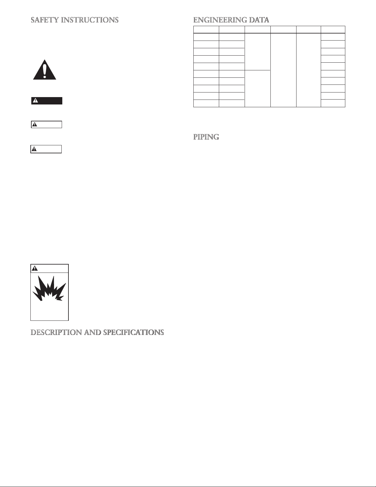
DANGER
CAUTION
WARNING
Hazardous Fluids
can cause fire,
burns or death.
SAFETY INSTRUCTIONS
TO AVOID SERIOUS OR FATAL PERSONAL INJURY
OR MAJOR PROPERTY DAMAGE, READ AND FOLLOW ALL SAFETY INSTRUCTIONS IN MANUAL AND
ON PUMP.
NOTICE: Indicates special instructions which are very
THIS MANUAL IS INTENDED TO ASSIST IN THE
INSTALLATION AND OPERATION OF THIS UNIT
AND MUST BE KEPT WITH THE PUMP.
THOROUGHLY REVIEW ALL INSTRUCTIONS AND
WARNINGS PRIOR TO PERFORMING ANY WORK
ON THIS PUMP.
MAINTAIN ALL SAFETY DECALS.
NOTICE: INSPECT UNIT FOR DAMAGE AND RE-
DESCRIPTION AND SPECIFICATIONS
• The Model GT embraces a line of end suction, single
• Casing is cast iron construction with tapped openings
• Impellers are enclosed design, glass filled Noryl
• Standard motors are NEMA standard, 3500 RPM,
This is a SAFETY ALERT SYMBOL.
When you see this symbol on the pump or
in the manual, look for one of the following signal words and be alert to the potential for personal injury or property damage.
Warns of hazards that WILL cause serious
personal injury, death or major property
damage.
WARNING
Warns of hazards that CAN cause serious
personal injury, death or major property
damage.
Warns of hazards that CAN cause personal
injury or property damage.
important and must be followed.
PORT ALL DAMAGE TO THE CARRIER
OR DEALER IMMEDIATELY. DO NOT
USE PUMP IF DAMAGE IS SUSPECTED.
UNITS NOT DESIGNED FOR USE
WITH HAZARDOUS LIQUIDS OR
FLAMMABLE GASES.
stage, self-priming centrifugal pumps for lawn sprinkling, HVAC systems, and general water transfer.
provided for vacuum gauge and casing drain.
TM
threaded directly on motor shaft.
open drip proof enclosure.
ENGINEERING DATA
Model HP Ph/Hz Suction Discharge Wt. lbs.
GT07 ¾ 48
GT10 1 52
GT15 1½ 1/60 60
GT20 2 65
GT30 3
GT073 ¾ 49
GT103 1 52
GT153 1½ 3/60 55
GT203 2 69
GT303 3 71
1½” NPT 1½” NPT
76
• Maximum Liquid Temperature: 160ºF (71ºC)
• Maximum Starts per Hour: 20 – evenly distributed
PIPING
• Pump MUST be installed horizontally on a solid flat
surface, with discharge on top.
• Allow adequate space for servicing and ventilation.
Protect the unit from weather and water damage due
to rain or flooding or freezing temperatures.
• Piping should be no smaller than the suction and dis-
charge connections and kept short as possible, avoiding
unnecessary fittings to minimize friction losses.
• All piping MUST be independently supported and
MUST NOT place any piping loads on the pump.
NOTICE: DO NOT FORCE PIPING INTO PLACE AT
PUMP SUCTION AND DISCHARGE CONNECTIONS.
• All pipe joints MUST be airtight.
• The use of Teflon
mended for ALL pipe joints.
SUCTION
TM
tape, or equivalent, is recom-
• Total suction lift, including elevation and pipe friction
loss, should not exceed 25 feet of head.
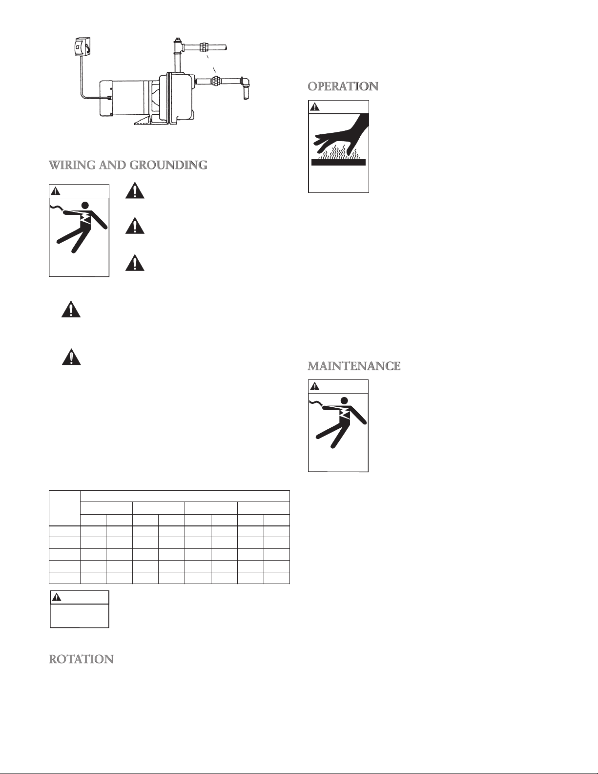
• Install an airtight union in the suction line close to the
pump. See Figure 1.
• Installation of a foot valve at liquid source is recom-
mended.
NOTICE: FOR INSTALLATIONS WITH LONG SUC-
TION PIPING, BOTH A FOOT VALVE
AND A CHECK VALVE ARE RECOMMENDED.
• To avoid air pockets, no part of the piping should be
above the pump suction connection and piping should
slope upward from liquid source.
,
• For installations with long suction piping, fill the suc-
tion pipe with water before connecting to pump.
DISCHARGE
• Install a tee at the discharge connection of the pump.
The top opening of the tee is required for initial priming. See Figure 1.
3
Page 4
WARNING
Hazardous voltage
can shock, burn or
cause death.
WARNING
Extreme heat can
cause personal injury
or property damage
PRIMING OPENING
WARNING
Hazardous voltage
can shock, burn or
cause death.
FUSED OR
CIRCUIT BREAKER
DISCONNECT MEANS
UNION
SUCTION
Figure 1
WIRING AND GROUNDING
Install, ground and wire according to local and National
Electrical Code requirements.
Install an all leg electrical power
disconnect switch near the
pump.
Disconnect electrical power
before installing or servicing
pump.
Electrical supply MUST match pump’s nameplate specification. Incorrect voltage can cause
fire or damage to the motor and voids warranty.
Motors without built-in protection MUST be
provided with contactors and thermal overloads for single phase motors, or starters with
heaters for three phase motors. See motor
nameplate.
• Follow motor manufacturer’s wiring diagram on the
motor nameplate or terminal cover carefully.
• Use only copper wire to motor and ground. The
ground wire MUST be at least as large as the wire to
the motor. Wires should be color coded for ease of
maintenance.
• Three phase unit rotation may be checked by removing
motor end cap or plug and observing rotation of motor
shaft. To reverse rotation, reverse any two of the three
motor leads.
OPERATION
OPERATION WITHOUT PRIME, OR
AGAINST A CLOSED DISCHARGE
VALVE, CAN GENERATE HOT WATER OR STEAM CAUSING INJURY
OR PROPERTY DAMAGE.
NOTICE: DO NOT OPERATE PUMP
WITHOUT PRIME OR
SEAL DAMAGE WILL
RESULT.
• Prime pump by filling pump and piping through open-
ing in top of tee with clean water. See Figure 1.
• Install pipe plug in top of tee using Teflon
™
tape or
equivalent.
NOTICE: IF PUMP IS DRAINED OR SHUT OFF
DURING PRIMING PERIOD, CASING
MUST BE REFILLED BEFORE RESTARTING PUMP.
• Start the pump and partially open discharge valve and
wait for system pressure to stabilize. If system pressure
is surging, or prolonged pressure drop is experienced,
the system may not be completely primed.
MAINTENANCE
FAILURE TO DISCONNECT ELECTRICAL POWER BEFORE ATTEMPTING ANY MAINTENANCE CAN
CAUSE SHOCK, BURNS OR DEATH.
• No lubrication is required on pump.
For motor lubrication, refer to and
follow manufacturer’s instructions.
RECOMMENDED MINIMUM WIRE SIZE
Distance from Service Entrance to Motor
HP 50 Ft. (15 m) 100 Ft. (30 m) 150 Ft. (46 m) 200 Ft. (61 m)
115 V 230 V 115 V 230 V 115 V 230 V 115 V 230 V
¾ 12 14 10 14 8 14 6 12
1 12 14 8 14 8 12 6 12
1½ 10 14 8 14 – 12 – 10
2 10 14 8 14 – 12 – 10
3 – 12 – 12 – 10 – 10
ROTATION
NOTICE: INCORRECT ROTATION MAY CAUSE
• Correct rotation is right hand, CLOCKWISE when
4
WARNING
Hazardous
voltage
FAILURE TO PERMANENTLY
GROUND THE PUMP, MOTOR AND
CONTROLS BEFORE CONNECTING TO ELECTRICAL POWER CAN
CAUSE SHOCK, BURNS, OR DEATH.
DAMAGE TO THE PUMP AND VOIDS
THE WARRANTY.
viewed from the motor end.
SEASONAL SERVICE
• To REMOVE pump from service, remove all drain
plugs and drain all piping.
• To RETURN pump to service, replace all drain plugs
using Teflon™ tape or equivalent.
• Reconnect suction line if removed, examine union and
repair if necessary.
• Reprime and operate pump following all instructions
and warnings in the “OPERATION” section of manu-
al.
Page 5
WARNING
Hazardous voltage
can shock, burn or
cause death.
DISASSEMBLY
WARNING
Hazardous voltage
can shock, burn or
cause death.
FAILURE TO DISCONNECT ELECTRICAL POWER BEFORE ATTEMPTING ANY MAINTENANCE CAN
CAUSE SHOCK, BURNS OR DEATH.
1. Remove foot bolt (10).
2. Remove casing bolts (12).
3. Remove back pull-out assembly from casing (2).
4. Remove diffuser seal ring (3) and diaphragm (4).
5. Remove diffuser screws (5) from adapter (11).
6. Remove motor end plug or cover.
7. Restrain motor shaft from rotation by utilization of
the screwdriver slot, or 7⁄16" shaft flats, accessible at
the motor shaft end.
8. Remove impeller (7), turning COUNTER-CLOCKWISE.
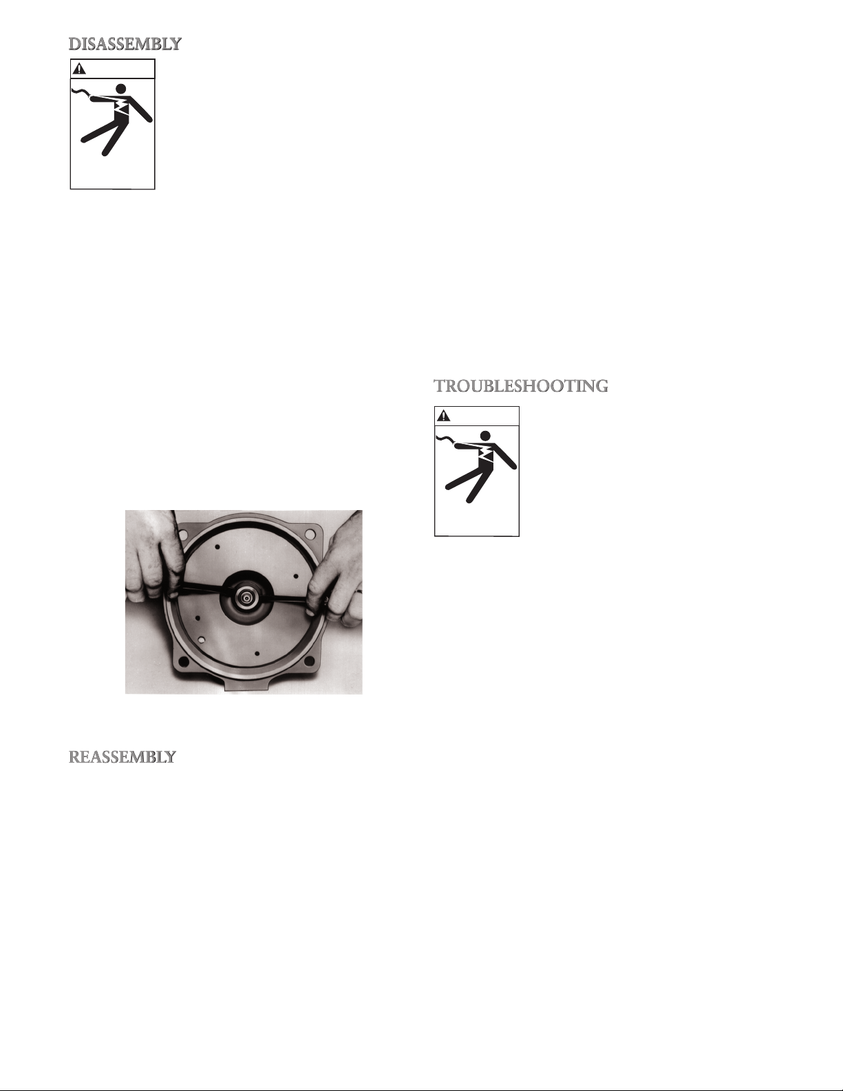
9. Using two screwdrivers, pry off rotary section of
mechanical seal (8). Discard. See Figure 2.
10. Remove motor adapter bolts (12) and remove motor
adapter from motor.
11. Push stationary seat of mechanical seal out of motor
adapter. Discard seal seat.
4. Fully and squarely install the seal rotary assembly
against the stationary seat. Be sure rotating seal face
does not drop out of holding collar and DO NOT
damage seal face.
5. On three phase units, impeller MUST be installed
with LOCTITE® “Purple”. Hold shaft from rotating,
as explained in the “DISASSEMBLY” section of the
manual, and install impeller by turning CLOCKWISE
until tight against motor shaft shoulder.
6. Replace diffuser. Align to prevent impeller rub.
7. Install new diaphragm and new diffuser seal ring.
8. Install motor and liquid end into casing.
9. Check impeller for binding by rotating the motor
shaft. If binding occurs, loosen casing bolts, readjust
diffuser until impeller hub turns freely. Retighten casing bolts in a crossing pattern.
10. Replace all drain plugs and motor end components.
11. Reprime and operate according to instructions in the
“OPERATION” section of this manual.
TROUBLESHOOTING
FAILURE TO DISCONNECT ELECTRICAL POWER BEFORE ATTEMPTING ANY MAINTENANCE CAN
CAUSE SHOCK, BURNS OR DEATH.
REASSEMBLY
• Clean and inspect all parts before reassembly.
1. Inspect seal seat bore for wear and debris, clean and
NOTICE: MECHANICAL SEAL MUST BE REPLACED
2. If necessary, seat ring may be lubricated with water or
3. Reinstall the motor adapter on the motor, making
Figure 2
replace as necessary.
WHENEVER SEAL HAS BEEN REMOVED.
FOLLOW SEAL MANUFACTURER’S INSTRUCTIONS CAREFULLY.
glycerin to aid in installation. DO NOT contaminate
the seal face. Fully and squarely install the stationary
seat into the adapter. With a clean, lint free cloth,
CAREFULLY wipe the seat face clean of debris. DO
NOT damage the seal seat face.
sure that the motor shaft does not dislocate or damage the stationary seal seat.
SYMPTOM
Motor Not Running:
See Probable Causes 1 through 5.
Little or No Water Delivered:
See Probable Causes 3, 4, 6 through 12, 15.
Excessive Noise and Vibration:
See Probable Causes 3, 6, 7, 10, 12, 13, 14.
PROBABLE CAUSES
1. Motor thermal protector tripped.
2. Open circuit breaker or blown fuse.
3. Impeller binding.
4. Motor improperly wired.
5. Defective motor.
6. Pump is not primed, air or gases in pumpage.
7. Discharge, suction plugged or valve closed.
8. Incorrect rotation. (3 phase only)
9. Low voltage or phase loss.
10. Impeller worn or plugged.
11. System head too high.
12. NPSHA too low – excessive suction lift or loss.
13. Discharge head too low – excessive flow rates.
14. Pump, motor or piping loose.
15. End of suction piping not submerged.
5
Page 6
ELECTRICAL DATA
Circuit Breaker
Model HP Voltage Full Load Amps Fuse Ph/Hz
Standard Delay
GT07 ¾ 115/230 13.8/6.9 45/25 45/25 25/15 1/60
GT10 1 115/230 16/8 50/25 50/25 30/15 1/60
GT15 1½ 115/230 20/10 60/30 60/35 35/20 1/60
GT20 2 230 13.9 40 40 25 1/60
GT30 3 230 17 60 60 30 1/60
GT073 ¾ 208-230/460 3.1-2.8/1.4 10-10/10 10-10/10 10-10/10 3/60
GT103 1 208-230/460 4-3.6/1.8 15-15/10 15-15/10 15-10/10 3/60
GT153 1½ 208-230/460 5.7-5.2/2.6 20-20/10 20-20/10 15-10/10 3/60
GT203 2 208-230/460 7.5-6.8/3.4 25-25/15 25-25/15 15-15/10 3/60
GT303 3 208-230/460 10.6-9.6/4.8 35-30/15 35-30/15 20-20/10 3/60
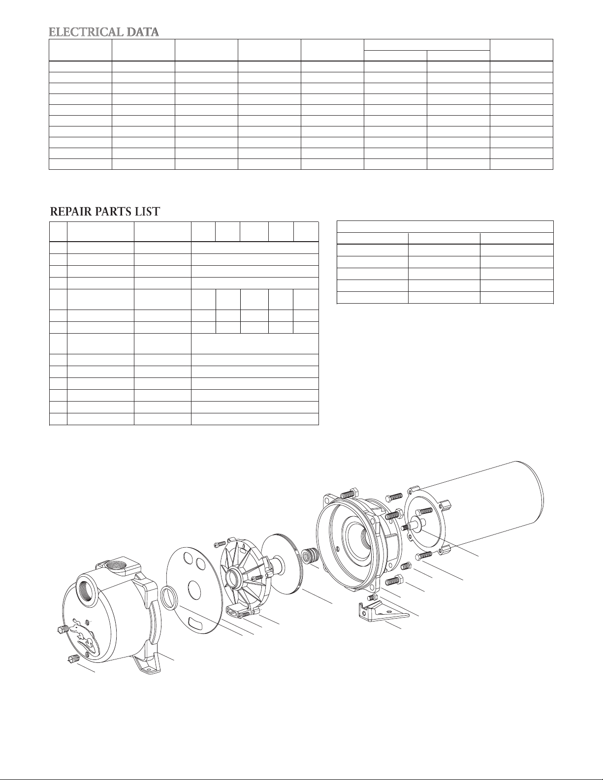
REPAIR PARTS LIST
Item GT07/ GT10/ GT15/ GT20/ GT30/
Description Material
No. GT073 GT103 GT153 GT203 GT303
1 ¼" NPT Pipe Plug Plated Steel 6K2
2 Casing Cast Iron 1K324
3 Guidevane Seal Ring BUNA 5K231
4 Diaphragm Neoprene 5K522
Fillister Head
5 Stainless Steel 13K4 13K4 13K2 13K2 13K2
Machine Screw
6 Guidevane Lexan® 10% G.F. 3K72 3K71 3K70 3K70 3K69
7 Impeller Noryl® 20% G.F. 2K715 2K716 2K714 2K713 2K712
Carbon/Ceramic/
8 Mechanical Seal 10K10
BUNA
9 Pump Foot Steel 4K408
10 Pump Foot Bolt Steel 13K252
11 Motor Adapter Cast Iron 1K310
12 Casing Bolt Steel 13K102
13 Motor Adapter Bolt Steel 13K89
14 Deflector BUNA 5K7
Motor Codes
HP 1Ø – ODP 3Ø – ODP
.75 J05853R C05873
1.0 J06853R C06873
1.5 J07858R C07878
2.0 J08854R C08874
3.0 J09853R C09874
14
8
7
6
5
4
3
2
1
6
11
9
10
12
1
13
Page 7

NOTES
7
Page 8

GOULDS WATER TECHNOLOGY LIMITED WARRANTY
This warranty applies to all water systems pumps manufactured by Goulds Water Technology.
Any part or parts found to be defective within the warranty period shall be replaced at no charge to the dealer during the warranty period. The warranty period shall exist for
a period of twelve (12) months from date of installation or eighteen (18) months from date of manufacture, whichever period is shorter.
A dealer who believes that a warranty claim exists must contact the authorized Goulds Water Technology distributor from whom the pump was purchased and furnish
complete details regarding the claim. The distributor is authorized to adjust any warranty claims utilizing the Goulds Water Technology Customer Service Department.
The warranty excludes:
(a) Labor, transportation and related costs incurred by the dealer;
(b) Reinstallation costs of repaired equipment;
(c) Reinstallation costs of replacement equipment;
(d) Consequential damages of any kind; and,
(e) Reimbursement for loss caused by interruption of service.
For purposes of this warranty, the following terms have these definitions:
(1) “Distributor” means any individual, partnership, corporation, association, or other legal relationship that stands between Goulds Water Technology and the dealer in
purchases, consignments or contracts for sale of the subject pumps.
(2) “Dealer” means any individual, partnership, corporation, association, or other legal relationship which engages in the business of selling or leasing pumps to
customers.
(3) “Customer” means any entity who buys or leases the subject pumps from a dealer. The “customer” may mean an individual, partnership, corporation, limited
liability company, association or other legal entity which may engage in any type of business.
THIS WARRANTY EXTENDS TO THE DEALER ONLY.
Xylem, Inc.
2881 East Bayard Street Ext., Suite A
Seneca Falls, NY 13148
Phone: (866) 325-4210
Fax: (888) 322-5877
www.gouldswatertechnology.com
Goulds is a registered trademark of Goulds Pumps, Inc. and is used under license.
© 2012 Xylem Inc. IM049 Revision Number 5 March 2013
Page 9

MANUAL DE INSTRUCCIÓN
IM049R05
™
GT IRRI-GATOR
BOMBAS CENTRÍFUGAS AUTOCEBANTES
INSTRUCCIONES DE INSTALACIÓN, OPERACIÓN Y MANTENIMIENTO
Page 10

ÍNDICE
TEMA PÁGINA
Instrucciones de seguridad ...........................................................................................................................................10
Descripción y especificaciones .....................................................................................................................................10
Datos de ingeniería ......................................................................................................................................................10
Tuberías Succión .........................................................................................................................................................10
Descarga .......................................................................................................................................................11
Alambrado y conexión a tierra ....................................................................................................................................11
Rotación ......................................................................................................................................................................11
Operación ...................................................................................................................................................................11
Mantenimiento ............................................................................................................................................................11
Desensamblaje .............................................................................................................................................................12
Reensamblaje ...............................................................................................................................................................12
Identificación y resolución de problemas .....................................................................................................................13
Datos eléctricos ...........................................................................................................................................................14
Lista de partes de repuesto ..........................................................................................................................................14
Garantía limitada ........................................................................................................................................................16
MODELOS E INFORMACIÓN DEL PROPIETARIO
Monofásica
GT07
GT10
GT15
GT20
GT30
Trifásica
GT073
GT103
GT153
GT203
GT303
Número de Modelo:
Número de Serie:
Agente:
No. telefónico del agente:
Fecha de compra:
Fecha de instalación:
10
Page 11

ADVERTENCIA
Los fluidos peligrosos
pueden causar
incendios, quemaduras
o la muerte.
INSTRUCCIONES DE SEGURIDAD
ADVERTENCIA
PRECAUCIÓN
PARA EVITAR LESIONES PERSONALES GRAVES O
AÚN FATALES Y SERIOS DAÑOS MATERIALES, LEA
Y SIGA TODAS LAS INSTRUCCIONES DE SEGURIDAD EN EL MANUAL Y EN LA BOMBA.
AVISO: Indica instrucciones especiales que son muy
importantes y que se deben seguir.
ESTE MANUAL HA SIDO CREADO COMO UNA
GUÍA PARA LA INSTALACIÓN Y OPERACIÓN DE
ESTA UNIDAD Y SE DEBE CONSERVAR JUNTO A
LA BOMBA.
EXAMINE BIEN TODAS LAS INSTRUCCIONES Y
ADVERTENCIAS ANTES DE REALIZAR CUALQUIER TRABAJO EN ESTA BOMBA.
MANTENGA TODAS LAS CALCOMANÍAS DE SEGURIDAD.
AVISO: INSPECCIONE LA UNIDAD PARA VER SI
TIENE DAÑOS Y NOTIFIQUE
INMEDIATAMENTE TODO DAÑO AL
TRANSPORTISTA O AL AGENTE. NO USE
LA BOMBA SI SOSPECHA QUE ESTÁ
DAÑADA.
DESCRIPCIÓN Y ESPECIFICACIONES
• El Modelo GT incluye una línea de bombas centrífugas
• La carcasa es de hierro fundido con oricios roscados
• Los impulsores son de diseño encerrado, Noryl™ lleno
• Los motores estándar tienen una cubierta NEMA están-
Éste es un SÍMBOLO DE ALERTA DE
SEGURIDAD. Cuando vea este símbolo
en la bomba o en el manual, busque una de
las siguientes palabras de señal y esté alerta
a la probabilidad de lesiones personales o
daños materiales.
PELIGRO
Advierte los peligros que CAUSARÁN
graves lesiones personales, la muerte o
daños materiales mayores.
Advierte los peligros que PUEDEN causar
graves lesiones personales, la muerte o
daños materiales mayores.
Advierte los peligros que PUEDEN causar
lesiones personales o daños materiales.
LAS UNIDADES NO ESTÁN DISEÑADAS PARA EL USO CON LÍQUIDOS
PELIGROSOS O GASES INFLAMABLES.
de autocebado, de una etapa, de extremo de succión
para aspersores de césped, sistemas de calefacción,
ventilación y aire acondicionado y para la transferencia
general de agua.
para el medidor de vacío y el drenaje de la carcasa.
con vidrio, roscados directamente sobre el eje del motor.
dar a prueba de explosión y operan a una velocidad de
3500 RPM.
DATOS DE INGENIERÍA
Modelo HP Fase/Hz Succión Descarga Peso libras
GT07 ¾ 48
GT10 1 52
GT15 1½ 1/60 60
GT20 2 65
GT30 3
GT073 ¾ 49
GT103 1 52
GT153 1½ 3/60 55
GT203 2 69
GT303 3 71
1½” NPT 1½” NPT
76
• Maximum Liquid Temperature: 160ºF (71ºC)
• Temperatura máxima del líquido: 160°F (71°C)
• Arranques máximos por hora: 20 – distribuidos uni-
formemente
TUBERÍAS
• La bomba DEBE instalarse horizontal sobre una
superficie plana sólida, con la descarga en el extremo
superior.
• Deje un espacio adecuado para el mantenimiento y la
ventilación. Proteja la unidad contra los daños causados por el mal tiempo y el agua de lluvia, inundación o
las temperaturas bajo cero.
• La tubería no debe ser más pequeña que las conexio-
nes de succión y descarga y debe mantenerse lo más
corta posible, evitando los accesorios innecesarios para
reducir al mínimo las pérdidas por fricción.
• Todas las tuberías DEBEN estar apoyadas en forma
independiente y NO DEBE aplicarse ninguna carga de
las tuberías sobre la bomba.
AVIS O: NO FUERCE LA TUBERÍA A SU POSICIÓN
EN LAS CONEXIONES DE SUCCIÓN O
DESCARGA DE LA BOMBA.
• Todas las juntas de tuberías DEBEN ser herméticas.
• Se recomienda usar cinta Teon™ o su equivalente en
TODAS las juntas de tuberías.
SUCCIÓN
• La elevación de succión total, incluso la elevación y la
pérdida por fricción del tubo, no debe sobrepasar 25
pies de altura.
• Instale una unión hermética en la línea de succión cerca
de la bomba. Ver la figura 1.
• Se recomienda instalar una válvula de aspiración en la
fuente de líquido.
AVISO: PARA LAS INSTALACIONES CON
TUBERÍA DE SUCCIÓN LARGA, SE
RECOMIENDA INSTALAR UNA VÁLVULA
DE ASPIRACIÓN Y UNA VÁLVULA DE
RETENCIÓN.
• Para evitar las bolsas de aire, ninguna parte de la tuber-
ía debe estar sobre la conexión de succión de la bomba
y la tubería debe tener una inclinación hacia arriba de la
fuente de líquido.
• Para instalaciones con tubería de succión larga, llene
la tubería de succión con agua antes de conectarla a la
bomba.
11
Page 12

ADVERTENCIA
Un voltaje peligroso puede
producir golpes el ctricos,
quemaduras o la muerte.
ADVERTENCIA
El calor extremo puede
causar lesiones
personales o daños
materiales.
ADVERTENCIA
Un voltaje peligroso puede
producir golpes el ctricos,
quemaduras o la muerte.
Tensión
p
eligrosa
ADVERTENCIA
DESCARGA
• Instale una T en la conexión de descarga de la bomba.
Se requiere la apertura del extremo superior de la T
para el cebado inicial. Ver la figura 1.
ABERTURA DE CEBADO
MEDIO DE
DESCONEXIÓN
POR FUSIBLE O
CORTACIRCUITOS
UNIÓN
SUCCIÓN
ROTACIÓN
AVISO: LA ROTACIÓN INCORRECTA PUEDE
CAUSAR DAÑO A LA BOMBA Y ANULAR
LA GARANTÍA.
• La rotación correcta es hacia la derecha, EN EL SEN-
TIDO DE LAS AGUJAS DEL RELOJ cuando se mira
desde el extremo del motor.
• La rotación trifásica puede vericarse quitando la
tapa o tapón del extremo del motor y observando la
rotación del eje del motor. Para invertir la rotación,
intercambie dos conductores eléctricos cualesquiera de
los tres conductores del motor.
ALAMBRADO Y CONEXIÓN A TIERRA
• Siga cuidadosamente el diagrama de alambrado del
• Use únicamente alambre de cobre para el motor y la
TAMAÑO MÍNIMO RECOMENDADO DEL ALAMBRE
Distancia desde la entrada de servicio al motor
HP 50 Pies (15 m) 100 Pies (30 m) 150 Pies (46 m) 200 Pies (61 m)
115 V 230 V 115 V 230 V 115 V 230 V 115 V 230 V
¾ 12 14 10 14 8 14 6 12
1 12 14 8 14 8 12 6 12
1½ 10 14 8 14 – 12 – 10
2 10 14 8 14 – 12 – 10
3 – 12 – 12 – 10 – 10
12
Figura 1
Instale, conecte a tierra y
alambre de acuerdo con los
requerimientos del Código Eléctrico Nacional o local.
Instale un desconectador de
todos los circuitos, cerca de la
bomba.
Desconecte la corriente eléctrica
antes de instalar o dar servicio a
la bomba.
El suministro eléctrico DEBE coincidir con
la especificación de la placa del fabricante de
la bomba. La tensión incorrecta puede causar
incendios, daños al motor y anular la garantía.
Los motores sin protección incorporada DE-
BEN estar equipados con contactadores y so-
brecargas térmicas para motores monofásicos,
o arrancadores con calentadores para motores
trifásicos. Ver la placa del fabricante del motor.
fabricante del motor en placa o en la cubierta de los
terminales del motor.
conexión a tierra. El alambre de conexión a tierra
DEBE ser al menos del mismo tamaño que el alambre
al motor. Los alambres deben codificarse con colores
para facilitar el mantenimiento.
LA FALLA DE CONECTAR A TIERRA
PERMANENTEMENTE LA BOMBA,
EL MOTOR Y LOS CONTROLES,
ANTES DE CONECTAR LA CORRIENTE ELÉCTRICA, PUEDE CAUSAR
CHOQUES, QUEMADURAS O LA
MUERTE.
OPERACIÓN
LA OPERACIÓN SIN CEBAR O CON
UNA VÁLVULA DE DESCARGA
CERRADA PUEDE GENERAR AGUA
CALIENTE O VAPOR QUE PUEDE
CAUSAR LESIONES O DAÑOS MATERIALES.
AVISO: NO OPERE LA BOMBA SIN
CEBARLA O SE DAÑARÁ
EL SELLO.
• Cebe la bomba llenando con agua limpia la bomba y la
tubería a través del orificio en el extremo superior de la
T. Ver la figura 1.
• Instale el tapón del tubo en el extremo superior de la T
empleando cinta Teflon™ o su equivalente.
AVISO: SI LA BOMBA SE DRENA O SE APAGA
DURANTE EL PERÍODO DE CEBADO, HAY
QUE LLENAR NUEVAMENTE LA CARCASA
ANTES DE REARRANCAR LA BOMBA.
• Arranque la bomba y abra parcialmente la válvula de
descarga y espere a que la presión del sistema se estabilice. Si la presión del sistema varía repentinamente o
se observa una caída de presión prolongada, no se ha
completado el cebado del sistema.
MANTENIMIENTO
LA FALLA DE DESCONECTAR
LA CORRIENTE ELÉCTRICA ANTES
DE INTENTAR CUALQUIER MANTENIMIENTO, PUEDE CAUSAR
CHOQUES, QUEMADURAS O
LA MUERTE.
• La bomba no requiere lubricación.
Consulte y siga las instrucciones del
fabricante para lubricar el motor.
SERVICIO DE TEMPORADA
• Para RETIRAR la bomba del servicio, quite todos los
tapones de drenaje y drene todas las tuberías.
• Para PONER OTRA VEZ en servicio la bomba, rein-
stale todos los tapones de drenaje empleando una cinta
Teflon™ o su equivalente.
• Reconecte la línea de succión si se había desconectado,
examine la unión y repárela si es necesario.
• Vuelva a cebar y opere la bomba siguiendo todas las
instrucciones y advertencias en la sección de “OPERACIÓN” del manual.
Page 13

ADVERTENCIA
Un voltaje peligroso puede
producir golpes el ctricos,
quemaduras o la muerte.
DESENSAMBLAJE
LA FALLA DE DESCONECTAR
LA CORRIENTE ELÉCTRICA ANTES
DE INTENTAR CUALQUIER MANTENIMIENTO, PUEDE CAUSAR
CHOQUES, QUEMADURAS O
LA MUERTE.
1. Quite el perno de la base (10).
2. Quite los pernos de la carcasa (12).
3. Retire el conjunto de desmontaje trasero de la carcasa
(2).
4. Retire el anillo de sello (3) y el diafragma (4) del difu-
sor.
5. Quite los tornillos (5) del adaptador (11) del difusor.
6. Quite el tapón o la cubierta del extremo del motor.
7. Utilice la ranura para destornillador o las secciones
planas del eje de 7-16 pulg. accesibles en el extremo
del eje del motor para restringir la rotación de dicho
eje.
8. Retire el impulsor (7) girando en SENTIDO
CONTRARIO A LAS AGUJAS DEL RELOJ.
9. Con dos destornilladores retire la sección giratoria
del sello mecánico (8). Deséchela. Ver la gura 2.
10. Quite los pernos del adaptador del motor (12) y
retire el adaptador.
11. Empuje el asiento estacionario del sello mecánico
fuera del adaptador del motor. Deseche el asiento del
sello.
Figura 2
REENSAMBLAJE
• Limpie e inspeccione todas las partes antes de reensamblar.
1. Inspeccione el agujero del asiento del sello para ver si
está gastado o sucio, límpielo si es necesario.
AVISO: ES NECESARIO REEMPLAZAR EL SELLO
MECÁNICO CADA VEZ QUE SE HAYA
RETIRADO. SIGA CUIDADOSAMENTE
LAS INSTRUCCIONES DEL FABRICANTE
DEL SELLO.
2. Si es necesario, el anillo del asiento puede lubricarse
con agua o glicerina para facilitar la instalación.
NO contamine la cara del sello. Instale el asiento
estacionario en forma completa y encuadrada en el
adaptador. Con un paño limpio y sin pelusas, quite
CUIDADOSAMENTE todos los residuos de la cara
del asiento. NO dañe la cara del asiento del sello.
3. Reinstale el adaptador del motor sobre el motor,
asegurándose de que el eje del motor no desplace o
dañe el asiento del sello estacionario.
4. Instale el conjunto giratorio del sello en forma
completa y encuadrada contra el asiento estacionario. Asegúrese de que la cara del sello giratorio no se
caiga fuera del collar de retención y NO dañe la cara
del sello.
5. En las unidades trifásicas, el impulsor DEBE insta-
larse con LOCTITE® “Purple”. Sujete el eje para que
no gire, tal como se explicó en la sección de “DES-
MONTAJE” del manual, e instale el impulsor girán-
dolo en SENTIDO DE LAS AGUJAS DEL RELOJ
hasta que quede ajustado contra el reborde del eje del
motor.
6. Reinstale el difusor. Alinéelo para evitar que roce con
el impulsor.
7. Instale el nuevo diafragma y el nuevo anillo del sello
del difusor.
8. Instale el motor y el extremo del líquido en la car-
casa.
9. Revise el impulsor para ver si roza girando el eje del
motor. Si hay roce, afloje los pernos de la carcasa,
reajuste el difusor hasta que el cubo del impulsor
gire libremente. Apriete nuevamente los pernos de la
carcasa en configuración cruzada.
10. Reinstale todos los tapones de drenaje y los compo-
nentes del extremo del motor.
11. Cebe nuevamente y opere de acuerdo con las in-
strucciones en la sección de “OPERACIÓN” de este
manual.
13
Page 14

ADVERTENCIA
Un voltaje peligroso puede
producir golpes el ctricos,
quemaduras o la muerte.
IDENTIFICACIÓN Y RESOLUCIÓN DE
PROBLEMAS
LA FALLA DE DESCONECTAR LA
CORRIENTE ELÉCTRICA ANTES
DE INTENTAR CUALQUIER MANTENIMIENTO, PUEDE CAUSAR
CHOQUES, QUEMADURAS O LA
MUERTE.
SÍNTOMA
El motor no funciona:
Ver las causas probables 1 a 5.
Se entrega poco o nada de agua:
Ver las causas probables 3, 4, 6 a 12, 15.
Ruido y vibración excesivos:
Ver las causas probables 3, 6, 7, 10, 12, 13, 14.
CAUSAS PROBABLES
1. Se disparó el protector térmico del motor.
2. Cortacircuitos abierto o fusible quemado.
3. Roce del impulsor.
4. Cableado incorrecto del motor.
5. Motor defectuoso.
6. La bomba no está cebada, hay aire o gases en el agua
bombeada.
7. Descarga o succión taponada o válvula cerrada.
8. Rotación incorrecta. (motor trifásico solamente)
9. Baja tensión o pérdida de fase.
10. Impulsor gastado o taponado.
11. Carga del sistema muy alta.
12. NPSHA demasiado baja – elevación o pérdida de suc-
ción excesiva.
13. Carga de descarga demasiado baja - velocidades de
flujo excesivas.
14. La bomba, el motor o la tubería está suelta.
15. El extremo de la tubería de succión no está sumer-
gido.
14
Page 15

DATOS ELÉCTRICOS
Cortacircuitos
Modelo HP Tensión Fusible Fase/Hz
Estándar De retardo
GT07 ¾ 115/230 13.8/6.9 45/25 45/25 25/15 1/60
GT10 1 115/230 16/8 50/25 50/25 30/15 1/60
GT15 1½ 115/230 20/10 60/30 60/35 35/20 1/60
GT20 2 230 13.9 40 40 25 1/60
GT30 3 230 17 60 60 30 1/60
GT073 ¾ 208-230/460 3.1-2.8/1.4 10-10/10 10-10/10 10-10/10 3/60
GT103 1 208-230/460 4-3.6/1.8 15-15/10 15-15/10 15-10/10 3/60
GT153 1½ 208-230/460 5.7-5.2/2.6 20-20/10 20-20/10 15-10/10 3/60
GT203 2 208-230/460 7.5-6.8/3.4 25-25/15 25-25/15 15-15/10 3/60
GT303 3 208-230/460 10.6-9.6/4.8 35-30/15 35-30/15 20-20/10 3/60
Corriente a plena
carga
LISTA DE PARTES DE REPUESTO
Art. Descripción Material GT07/ GT10/ GT15/ GT20/ GT30/
N°. GT073 GT103 GT153 GT203 GT303
1 Tapón de tubo NPT Acero enchapado 6K2
de 1⁄4 pulg.
2 Carcasa Hierro fundido 1K324
3 Anillo de sello del BUNA 5K231
álabe guía
4 Diafragma Neopreno 5K522
Tornillo para metales
5 de cabeza cilíndrica Acero inoxidable 13K4 13K4 13K2 13K2 13K2
ranurada
6 Álabe guía Lexan 3K72 3K71 3K70 3K70 3K69
7 Impulsor Noryl 2K715 2K716 2K714 2K713 2K712
8 Sello mecánico Carbón/Cerámica/ 10K10
BUNA
9 Base de la bomba Acero 4K408
10 Perno de la base de Acero 13K252
la bomba
11 Adaptador del motor Hierro fundido 1K310
12 Perno de la carcasa Acero 13K102
13 Perno del adaptador Acero 13K89
del motor
14 Deflector BUNA 5K7
Códigos de Motores
HP 1Ø – ODP 3Ø – ODP
.75 J05853R C05873
1.0 J06853R C06873
1.5 J07858R C07878
2.0 J08854R C08874
3.0 J09853R C09874
14
8
7
6
5
4
3
2
1
11
9
10
12
1
13
15
Page 16

GARANTÍA LIMITADA DE GOULDS WATER TECHNOLOGY
Esta garantía es aplicable a todas las bombas para sistemas de agua fabricadas por Goulds Water Technology. Toda parte o partes que resultaren defectuosas dentro del período
de garantía serán reemplazadas, sin cargo para el comerciante, durante dicho período de garantía. Tal período de garantía se extiende por doce (12) meses a partir de la fecha
de instalación, o dieciocho (18) meses a partir de la fecha de fabricación, cualquiera se cumpla primero.
Todo comerciante que considere que existe lugar a un reclamo de garantía deberá ponerse en contacto con el distribuidor autorizado de Goulds Water Technology del cual adquiriera la bomba y ofrecer información detallada con respecto al reclamo. El distribuidor está autorizado a liquidar todos los reclamos por garantía a través del Departamento
de Servicios a Clientes de Goulds Water Technology.
La presente garantía excluye:
(a) La mano de obra, el transporte y los costos relacionados en los que incurra el comerciante;
(b) los costos de reinstalación del equipo reparado;
(c) los costos de reinstalación del equipo reemplazado;
(d) daños emergentes de cualquier naturaleza; y
(e) el reembolso de cualquier pérdida causada por la interrupción del servicio
A los fines de esta garantía, los términos “Distribuidor”, “Comerciante” y “Cliente” se definen como sigue:
(1) “Distribuidor” es aquel individuo, sociedad, corporación, asociación u otra persona jurídica que opera en relación legal entre Goulds Water Technology y el comerciante
para la compra, consignación o contratos de venta de las bombas en cuestión.
(2) “Comerciante” es todo individuo, sociedad, corporación, asociación u otra persona jurídica que en el marco de una relación legal realiza negocios de venta o alquiler-venta
(leasing) de bombas a clientes.
(3) “Cliente” es toda entidad que compra o que adquiere bajo la modalidad de leasing las bombas en cuestión de un comerciante. El término “cliente” puede significar un
individuo, sociedad, corporación, sociedad de responsabilidad limitada, asociación o cualquier otra persona jurídica con actividades en cualquier tipo de negocios.
LA PRESENTE GARANTÍA SE EXTIENDE AL COMERCIANTE ÚNICAMENTE.
Xylem, Inc.
2881 East Bayard Street Ext., Suite A
Seneca Falls, NY 13148
Teléfono: (866) 325-4210
Fax: (888) 322-5877
www.gouldswatertechnology.com
Goulds es una marca registrada de Goulds Pumps, Inc. y se utiliza bajo licencia.
© 2012 Xylem Inc. IM049 Revisión Número 5 Marzo 2013
Page 17

MANUEL D'UTILISATION
IM049R05
MC
GT IRRI-GATOR
MODÈLE AUTOAMORÇANT
DIRECTIVES D’INSTALLATION, D’UTILISATION ET D’ENTRETIEN
Page 18

TABLE DES MATIÈRES
SUJET PAGE
Consignes de sécurité ..................................................................................................................................................18
Description et caractéristiques .....................................................................................................................................18
Données techniques .....................................................................................................................................................18
Tuyauterie Aspiration ................................................................................................................................................18
Refoulement ............................................................................................................................................19
Câblage et mise à la terre .............................................................................................................................................19
Sens de rotation ...........................................................................................................................................................19
Utilisation ....................................................................................................................................................................19
Entretien .....................................................................................................................................................................19
Démontage ..................................................................................................................................................................20
Remontage ..................................................................................................................................................................20
Diagnostic des anomalies .............................................................................................................................................20
Données sur l’alimentation électrique ..........................................................................................................................21
Liste de pièces de rechange ..........................................................................................................................................21
Garantie limitée de Goulds Water Technology .............................................................................................................24
MODÈLE ET INFORMATIONS POUR LE PROPRIÉTAIRE
Monophasé
GT07
GT10
GT15
GT20
GT30
Triphasé
GT073
GT103
GT153
GT203
GT303
Numéro de modèle :
Numéro de série :
Détaillant :
Téléphone (détaillant) :
Date d’achat :
Date d’installation :
18
Page 19

DANGER
AVERTISSEMENT
ATTENTION
AVERTISSEMENT
Les fluides dangereux
peuvent causer un
incendie, des brûlures
ou la mort.
CONSIGNES DE SÉCURITÉ
AFIN DE PRÉVENIR LES BLESSURES GRAVES OU
MORTELLES ET LES DOMMAGES MATÉRIELS
IMPORTANTS, LIRE ET SUIVRE TOUTES LES CONSIGNES DE SÉCURITÉ FIGURANT DANS LE MANUEL ET SUR LA POMPE.
AVIS : Sert à énoncer les directives spéciales de grande
importance que l’on doit suivre.
LE PRÉSENT MANUEL A POUR BUT DE FACILITER
L’INSTALLATION ET L’UTILISATION DE LA POMPE
ET DOIT ÊTRE CONSERVÉ PRÈS DE CELLE-CI.
LIRE SOIGNEUSEMENT CHAQUE DIRECTIVE ET
AVERTISSEMENT AVANT D’EFFECTUER TOUT
TRAVAIL SUR LA POMPE.
N’ENLEVER AUCUNE DÉCALCOMANIE DE SÉCURITÉ.
AVIS : INSPECTER L’APPAREIL ET SIGNALER
IMMÉDIATEMENT TOUT DOMMAGE AU
TRANSPORTEUR OU AU DÉTAILLANT. NE
PAS UTILISER L’APPAREIL SI L’ON
SOUPÇONNE QU’IL EST ENDOMMAGÉ.
DESCRIPTION ET CARACTÉRISTIQUES
• Le modèle GT englobe une gamme de pompes cen-
• Le corps de pompe est en fonte et comporte des
• La roue est du type fermé en NorylMC chargé de fibre
• Les moteurs standard sont du type abrité, conforme
Le symbole ci-contre est un SYMBOLE
DE SÉCURITÉ employé pour signaler
les mots-indicateurs dont on trouvera la
description ci-dessous. Sa présence sert à
attirer l’attention afin d’éviter les blessures
et les dommages matériels.
Prévient des risques qui VONT causer des
blessures graves, la mort ou des dommages
matériels importants.
Prévient des risques qui PEUVENT causer
des blessures graves, la mort ou des dommages matériels importants.
Prévient des risques qui PEUVENT causer
des blessures ou des dommages matériels.
APPAREIL NON CONÇU POUR LES
LIQUIDES DANGEREUX NI POUR
LES GAZ INFLAMMABLES.
trifuges autoamorçantes, à un étage et à aspiration en
bout, servant à l’arrosage des pelouses, aux systèmes
CVCA ( chauffage, ventilation et conditionnement
d’air ) et au transfert d’eau de nature générale.
orifices taraudés pour la vidange et pour la pose d’un
vacuomètre.
de verre et est vissée sur l’arbre de moteur.
à la NEMA et ont une vitesse de rotation de 3 500 tr/
min.
DONNÉES TECHNIQUES
Modèle hp PH/Hz Aspiration Refoulement Poids (lb)
GT07 ¾ 48
GT10 1 52
GT15 1½ 1/60 60
GT20 2 65
1½ po, 1½ po,
GT30 3 76
NPT NPT
GT073 ¾ 49
GT103 1 52
GT153 1½ 3/60 55
GT203 2 69
GT303 3 71
• Température maximale du liquide : 71 °C (160 °F)
• Démarrages par heure : maximum de 20, répartis
uniformément
TUYAUTERIE
• On DOIT installer la pompe sur une surface plane,
horizontale et solide, l’orifice de refoulement vers le
haut.
• Laisser sufsamment d’espace pour l’entretien et
l’aération. Protéger l’appareil contre les intempéries,
les inondations et le gel.
• An de réduire les pertes de charge (par frottement)
au minimum, maintenir la tuyauterie aussi courte que
possible, ne pas employer un calibre de tuyau inférieur
à celui des raccords d’aspiration et de refoulement
ni utiliser d’accessoires ou de raccords de tuyauterie
superflus.
• Tous les tuyaux DOIVENT posséder leurs propres
supports. Ils NE DOIVENT appliquer AUCUNE contrainte sur la pompe.
AVIS : LA TUYAUTERIE NE DOIT PAS APPLIQUER
DE CONTRAINTES SUR LES RACCORDS
D’ASPIRATION ET DE REFOULEMENT DE
LA POMPE.
• Chaque joint de tuyauterie DOIT être étanche.
• L’emploi de ruban de TéonMC ou l’équivalent est
recommandé pour TOUS les joints de tuyauterie.
ASPIRATION
• La hauteur d’aspiration ne devrait pas dépasser 25
pi en tenant compte de l’élévation et de la perte de
charge.
• Poser un raccord union étanche sur le tuyau
d’aspiration, près de la pompe (v. fig. 1).
• On recommande de xer un clapet de pied à l’entrée
(qui sera immergée) du tuyau d’aspiration.
AVIS : POUR LES LONGS TUYAUX D’ASPIRATION,
ON RECOMMANDE LA POSE D’UN
CLAPET DE PIED ET D’UN CLAPET DE
NON-RETOUR.
• An de prévenir les poches d’air, aucun élément de la
tuyauterie d’aspiration ne devrait être plus haut que le
raccord d’aspiration de la pompe. Incliner la tuyauterie
vers le haut à partir de la source de liquide.
• Si le tuyau d’aspiration est de longueur importante, le
remplir d’eau avant de le raccorder à la pompe.
19
Page 20

AVERTISSEMENT
Les tensions dangereuses
peuvent causer un choc
électrique, des brûlures
et la mort.
Les hautes températures
peuvent causer des
blessures et des
dommages matériels.
AVERTISSEMENT
AVERTISSEMENT
Les tensions dangereuses
peuvent causer un choc
électrique, des brûlures
et la mort.
AVERTISSEMENT
Tension
dangereuse
REFOULEMENT
• Poser au-dessus de l’orice de refoulement un té dont
CÂBLAGE ET MISE À LA TERRE
• Suivre soigneusement le schéma de câblage sur la
• N’utiliser que du l de cuivre pour la mise à la terre
CALIBRE DE FIL MINIMAL RECOMMANDÉ
Distance entre l’entrée de service et le moteur
hp 15 m (50 pi) 30 m (100 pi) 46 m (150 pi) 61 m (200 pi)
115 V 230 V 115 V 230 V 115 V 230 V 115 V 230 V
¾ 12 14 10 14 8 14 6 12
1 12 14 8 14 8 12 6 12
1½ 10 14 8 14 – 12 – 10
2 10 14 8 14 – 12 – 10
3 – 12 – 12 – 10 – 10
20
une branche sera orientée vers le haut pour servir au
premier amorçage de la pompe (v. fig. 1).
ORIFICE D’AMORÇAGE
SECTIONNEUR
À FUSIBLES OU
DISJONCTEUR
RACCORDS UNIONS
ASPIRATION
Figure 1
Poser le fil de terre et les autres
fils suivant les prescriptions du
code provincial ou national de
l’électricité.
Poser un sectionneur tout conducteur près de la pompe.
Couper le courant avant de
procéder à l’installation ou à
l’entretien de la pompe.
L’alimentation électrique DOIT être conforme
aux spécifications de la plaque signalétique.
Une tension inappropriée peut causer un incendie ou des dommages au moteur et annule
la garantie.
Les moteurs monophasés non protégés DOI-
VENT être munis de contacteurs et de dispositifs de protection contre les surcharges thermiques, et les moteurs triphasés, de démarreurs
à dispositif de protection contre la surcharge.
Consulter la plaque signalétique du moteur.
plaque signalétique ou le cache-bornes du moteur.
et l’alimentation du moteur. Le calibre du fil de terre
DOIT être au moins égal à celui des fils d’alimentation,
et les fils devraient tous être chromocodés pour faciliter
l’entretien.
OMETTRE LA MISE À LA TERRE
PERMANENTE DE LA POMPE, DU
MOTEUR ET DES COMMANDES
AVANT LE BRANCHEMENT À
LA SOURCE DE COURANT PEUT
CAUSER UN CHOC ÉLECTRIQUE,
DES BRÛLURES OU LA MORT.
SENS DE ROTATION
AVIS : LA ROTATION DANS LE MAUVAIS SENS
PEUT ENDOMMAGER LA POMPE ET
ANNULE LA GARANTIE.
• La rotation appropriée est en SENS HORAIRE (vers
la droite), vue de l’extrémité du moteur.
• On peut vérier le sens de rotation de l’arbre d’un
moteur triphasé en ôtant l’obturate ur ou le couvercle
d’extrémité du moteur. Pour inverser la rotation de
celui-ci, en intervertir deux des trois conducteurs.
UTILISATION
L’UTILISATION D’UNE POMPE DÉSAMORCÉE OU DONT LE ROBINET
DE REFOULEMENT EST FERMÉ
PEUT PROVOQUER UN ÉCHAUFFEMENT, TRANSFORMER AINSI
L’EAU EN VAPEUR ET CAUSER DES
BLESSURES ET DES DOMMAGES
MATÉRIELS.
AVIS : NE PAS UTILISER UNE POMPE
DÉSAMORCÉE AFIN DE NE PAS EN
ENDOMMAGER LES DISPOSITIFS
D’ÉTANCHÉITÉ.
• Amorcer la pompe en remplissant cette dernière et la
tuyauterie d’eau propre par l’orifice supérieur du té (v.
fig. 1).
• Recouvrir les lets du bouchon d’amorçage de ruban
de TéflonMC ou l’équivalent et visser le bouchon sur le
té.
AVIS : SI LA POMPE SE VIDE OU S’ARRÊTE
PENDANT L’AMORÇAGE, ON DOIT
LA REMPLIR DE NOUVEAU, PUIS
LA REMETTRE EN MARCHE.
• Mettre la pompe en marche, entrouvrir le robinet de
refoulement et attendre que la pression se stabilise. Des
à-coups de pression ou une chute de pression prolongée indiquent un amorçage incorrect.
ENTRETIEN
OMETTRE DE COUPER LE COURANT AVANT TOUT TRAVAIL
D’ENTRETIEN PEUT CAUSER
UN CHOC ÉLECTRIQUE, DES
BRÛLURES OU LA MORT.
• La pompe ne nécessite aucune
lubrification. Quant au moteur,
consulter et suivre les directives du
fabricant.
USAGE SAISONNIER
• Pour la MISE HORS SERVICE, déposer tous les
bouchons de vidange et vider tous les tuyaux.
• Pour la REMISE EN SERVICE, reposer tous les
bouchons de vidange après en avoir recouvert les filets
de ruban de TéflonMC ou l’équivalent.
• Raccorder le tuyau d’aspiration à la pompe s’il a été
désaccouplé, examiner le raccord union et effectuer les
réparations nécessaires.
• Réamorcer et faire fonctionner la pompe suivant les
directives et les avertissements de la section
« UTILISATION » ci-dessus.
Page 21

AVERTISSEMENT
Les tensions dangereuses
peuvent causer un choc
électrique, des brûlures
et la mort.
DÉMONTAGE
OMETTRE DE COUPER LE COURANT AVANT TOUT TRAVAIL
D’ENTRETIEN PEUT CAUSER
UN CHOC ÉLECTRIQUE, DES
BRÛLURES OU LA MORT.
1. Enlever la vis (10) de la patte de pompe.
2. Déposer les vis (12) du corps de pompe (2).
3. Écarter l’ensemble d’entraînement de la roue d’avec
le corps de pompe.
4. Enlever la bague d’étanchéité (3) du diffuseur ainsi
que la membrane (4).
5. Ôter les vis de fixation (5) du diffuseur à l’adaptateur
(11).
6. Déposer l’obturateur ou le couvercle d’extrémité du
moteur.
7. Immobiliser l’arbre de moteur au moyen de la
fente ou des méplats de blocage de 7⁄16 po situés à
l’extrémité de l’arbre.
8. Dévisser (SENS ANTIHORAIRE) et enlever la roue
(7).
9. Employer deux tournevis en guise de leviers et ex-
traire l’élément mobile de la garniture mécanique (8),
puis le jeter (v. fig. 2).
10. Enlever les vis (12) de l’adaptateur et déposer celui-ci.
11. Pousser l’élément fixe de la garniture mécanique hors
de l’adaptateur et le jeter.
REMONTAGE
• Nettoyer et inspecter chaque pièce avant le remontage.
1. Vérifier s’il y a présence de résidus ou d’usure sur
le siège de garniture mécanique. Le nettoyer ou le
remplacer au besoin.
AVIS : ON DOIT CHANGER LA GARNITURE
MÉCANIQUE CHAQUE FOIS QU’ON
L’ENLÈVE. SUIVRE LES DIRECTIVES DU
FABRICANT DE LA GARNITURE AVEC
SOIN.
2. Au besoin, mouiller ou glycériner l’élément fixe de
la garniture mécanique pour en faciliter la pose. NE
PAS le contaminer. Le pousser à fond et à angle droit
dans son siège, sur l’adaptateur. Avec un linge propre
non pelucheux, le nettoyer AVEC SOIN. NE PAS
l’endommager.
3. Poser l’adaptateur sur le moteur en s’assurant que
l’arbre de moteur ne déloge ni n’endommage le siège
de l’élément fixe.
4. Pousser l’ensemble élément mobile à fond et à angle
droit contre l’élément fixe. S’assurer que l’élément
mobile est bien maintenu en place par son collet de
retenue. NE PAS endommager la garniture mécanique.
5. Dans le cas des moteurs triphasés, on DOIT employ-
er du LOCTITEMD violet (« Purple ») pour poser
la roue. Bloquer l’arbre (v. section « DÉMONTAGE
») et visser la roue à fond sur l’arbre en SENS HO-
RAIRE.
6. Remettre le diffuseur en place tout en l’alignant pour
empêcher la roue de frotter.
7. Poser une membrane et une bague d’étanchéité (dif-
fuseur) neuves.
8. Réinsérer l’ensemble d’entraînement de la roue dans
le corps de pompe.
9. Tourner l’arbre de moteur pour vérifier si la roue
est grippée. Si elle l’est, desserrer les vis du corps de
pompe, déplacer le diffuseur jusqu’à ce que la roue
tourne librement, puis resserrer les vis, en croix.
10. Remettre chaque bouchon de vidange et composant
côté moteur en place.
11. Réamorcer et faire fonctionner la pompe suivant les
directives de la section « UTILISATION » ci-dessus.
Figure 2
21
Page 22

DIAGNOSTIC DES ANOMALIES
AVERTISSEMENT
Les tensions dangereuses
peuvent causer un choc
électrique, des brûlures
et la mort.
OMETTRE DE COUPER LE COURANT AVANT TOUT TRAVAIL
D’ENTRETIEN PEUT CAUSER
UN CHOC ÉLECTRIQUE, DES
BRÛLURES OU LA MORT.
ANOMALIE
Non-fonctionnement du moteur
(V. causes probables 1 à 5)
Débit de refoulement faible ou nul
(V. causes probables 3, 4, 6 à 12 et 15)
Vibration et bruit excessifs
(V. causes probables 3, 6, 7, 10, 12, 13 et 14)
CAUSE PROBABLE
1. Protecteur thermique du moteur déclenché
2. Disjoncteur ouvert ou fusible sauté
3. Roue grippée
4. Moteur mal connecté
5. Moteur défectueux
6. Pompe non amorcée, air ou gaz présent dans le liq-
uide pompé
7. Tuyau d’aspiration ou de refoulement obstrué ou
robinet fermé
8. Mauvais sens de rotation (moteurs triphasés seule-
ment)
9. Basse tension électrique ou perte de phase
10. Roue usée ou engorgée
11. Hauteur de charge du système trop élevée
12. Hauteur nette d’aspiration disponible (NPSHA) trop
faible – hauteur ou perte d’aspiration excessives
13. Hauteur de refoulement trop faible – débit excessif
14. Pompe, moteur ou tuyauterie mal assujettis
15. Entrée du tuyau d’aspiration non immergée
22
Page 23

DONNÉES SUR L’ALIMENTATION ÉLECTRIQUE
Disjoncteur
Modèle hp Tension (V) Fusible PH/Hz
Standard Retardé
GT07 ¾ 115/230 13,8/6,9 45/25 45/25 25/15 1/60
GT10 1 115/230 16/8 50/25 50/25 30/15 1/60
GT15 1½ 115/230 20/10 60/30 60/35 35/20 1/60
GT20 2 230 13,9 40 40 25 1/60
GT30 3 230 17 60 60 30 1/60
GT073 ¾ 208-230/460 3,1-2,8/1,4 10-10/10 10-10/10 10-10/10 3/60
GT103 1 208-230/460 4-3,6/1,8 15-15/10 15-15/10 15-10/10 3/60
GT153 1½ 208-230/460 5,7-5,2/2,6 20-20/10 20-20/10 15-10/10 3/60
GT203 2 208-230/460 7,5-6,8/3,4 25-25/15 25-25/15 15-15/10 3/60
GT303 3 208-230/460 10,6-9,6/4,8 35-30/15 35-30/15 20-20/10 3/60
Courant (A) à
pleine charge
LISTE DE PIÈCES DE RECHANGE
No GT07/ GT10/ GT15/ GT20/ GT30/
Description Matériau
d’art. GT073 GT103 GT153 GT203 GT303
1 Bouchon, ¼ po, NPT Acier galvanisé 6K2
2 Corps de pompe Fonte 1K324
3 Bague d’étanchéité Buna 5K231
(diffuseur)
4 Membrane Néoprène 5K522
5 Vis à métaux à tête Inox 13K4 13K4 13K2 13K2 13K2
cylindrique bombée
6 Diffuseur Lexan + FV (10 %) 3K72 3K71 3K70 3K70 3K69
7 Roue Noryl + FV (20 %) 2K715 2K716 2K714 2K713 2K712
8 Garniture mécanique Carbone, 10K10
céramique, buna
9 Patte de pompe Acier 4K408
10 Vis (patte de pompe) Acier 13K252
11 Adaptateur (moteur) Fonte 1K310
12
Vis (corps de pompe)
13 Vis (adaptateur) Acier 13K89
14 Déflecteur Buna 5K7
FV = fibre de verre
Acier 13K102
Codes de Moteur
hp 1 Ø, abrité 3 Ø, abrité
0,75 J05853R C05873
1,0 J06853R C06873
1,5 J07858R C07878
2,0 J08854R C08874
3,0 J09853R C09874
14
8
7
6
5
4
3
2
1
11
9
10
12
1
13
23
Page 24

GARANTIE LIMITÉE DE GOULDS WATER TECHNOLOGY
La présente garantie s’applique à chaque pompe de système d’alimentation en eau fabriquée par Goulds Water Technology.
Toute pièce se révélant défectueuse sera remplacée sans frais pour le détaillant durant la période de garantie suivante expirant la première : douze (12) mois à compter de la
date d’installation ou dix-huit (18) mois à partir de la date de fabrication.
Le détaillant qui, aux termes de cette garantie, désire effectuer une demande de règlement doit s’adresser au distributeur Goulds Water Technology agréé chez lequel la pompe
a été achetée et fournir tous les détails à l’appui de sa demande. Le distributeur est autorisé à régler toute demande par le biais du service à la clientèle de Goulds Water Technology.
La garantie ne couvre pas :
a) les frais de main-d’œuvre ou de transport ni les frais connexes encourus par le détaillant ;
b) les frais de réinstallation de l’équipement réparé ;
c) les frais de réinstallation de l’équipement de remplacement ;
d) les dommages indirects de quelque nature que ce soit ;
e) ni les pertes découlant de la panne.
Aux fins de la présente garantie, les termes ci-dessous sont définis comme suit :
1) « Distributeur » signifie une personne, une société de personnes, une société de capitaux, une association ou autre entité juridique servant d’intermédiaire entre Goulds
Water Technology et le détaillant pour les achats, les consignations ou les contrats de vente des pompes en question.
2) « Détaillant » veut dire une personne, une société de personnes, une société de capitaux, une association ou autre entité juridique dont les activités commerciales sont la
vente ou la location de pompes à des clients.
3) « Client » signifie une entité qui achète ou loue les pompes en question chez un détaillant. Un « client » peut être une personne, une société de personnes, une société de
capitaux, une société à responsabilité limitée, une association ou autre entité juridique se livrant à quelque activité que ce soit.
CETTE GARANTIE SE RAPPORTE AU DÉTAILLANT SEULEMENT.
Xylem, Inc.
2881 East Bayard Street Ext., Suite A
Seneca Falls, NY 13148
Téléphone: (866) 325-4210
Télécopie: (888) 322-5877
www.gouldswatertechnology.com
Goulds est une marque déposée de Goulds Pumps, Inc. et est utilisé sous le permis.
© 2012, Xylem Inc. IM049 Révision numéro 5 Mars 2013
 Loading...