

Page 1

INSTRUCTION MANUAL
IM042
Slide Rail Systems -
Series A10
INSTALLATION, OPERATION AND MAINTENANCE INSTRUCTIONS
Page 2
TABLE OF CONTENTS
SUBJECT PAGE
Safety Instructions ........................................................................................................................................................ 3
Descriptions and Specifications ..................................................................................................................................... 3
Piping ........................................................................................................................................................................... 3
Slide Rail Installation .................................................................................................................................................... 3
Operation ..................................................................................................................................................................... 6
Working Load Limits .................................................................................................................................................... 6
Warnings ...................................................................................................................................................................... 6
Limited Warranty .........................................................................................................................................................8
Owner’s Information
Pump Model Number:
Pump Serial Number:
Control Model Number:
Dealer:
Dealer Phone No.
Date of Purchase: Installation:
2
Page 3
SAFETY INSTRUCTIONS
DANGER
WARNING
CAUTION
WARNING
Hazardous voltage
can shock, burn or
cause death.
TO AVOID SERIOUS OR FATAL PERSONAL
INJURY OR MAJOR PROPERTY DAMAGE, READ
AND FOLLOW ALL SAFETY INSTRUCTIONS IN
MANUAL AND ON PUMP.
THIS MANUAL IS INTENDED TO ASSIST IN THE
INSTALLATION AND OPERATION OF THIS UNIT
AND MUST BE KEPT WITH THE SLIDE RAIL.
MAINTAIN ALL SAFETY DECALS.
DESCRIPTIONS AND SPECIFICATIONS
Goulds Pumps A10 slide rail systems provide easy wet
well pump removal, utilize a self-cleaning quick disconnect and guide assembly, and eliminate the need to enter
the wet well.
Model Slide Rail Discharge Pump Discharge
A10-12 1¼” NPTM 1¼” F
A10-2015 1½” NPTM 1½” F
A10-20 2” NPTM 2” F
A10-30 and 4” 125#
A10-40 ANSI Flange
ANSI Flange
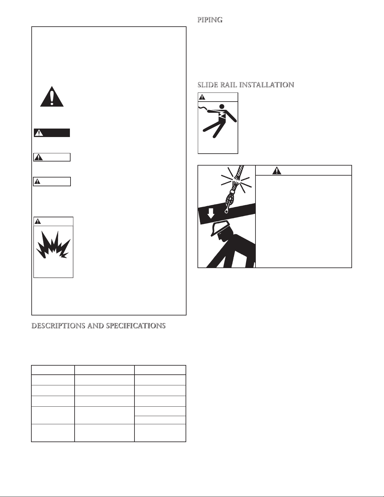
This is a SAFETY ALERT SYMBOL.
When you see this symbol on the pump
or in the manual, look for one of the following signal words and be alert to the
potential for personal injury or property
damage.
Warns of hazards that WILL cause
serious personal injury, death or major
property damage.
Warns of hazards that CAN cause
serious personal injury, death or major
property damage.
Warns of hazards that CAN cause personal injury or property damage.
NOTICE: INDICATES SPECIAL INSTRUCTIONS
WHICH ARE VERY IMPORTANT AND
MUST BE FOLLOWED.
WARNING
HAZARDOUS LIQUIDS OR
FLAMMABLE GASES CAN CAUSE
FIRE, BURNS OR DEATH.
THOROUGHLY REVIEW ALL
INSTRUCTIONS AND WARNINGS
Hazardous fluids
can cause fire,
burns or death.
PRIOR TO PERFORMING ANY
WORK ON THIS UNIT.
NOTICE: INSPECT UNIT FOR DAMAGE AND
REPORT ALL DAMAGE TO THE
CARRIER OR DEALER IMMEDIATELY.
3” ANSI Flange
4” ANSI Flange
A10-60
6” 125#
4” ANSI Flange
PIPING
System piping MUST conform to all local and national
plumbing codes and practices.
To maximize the discharge flow, discharge piping should
be at least as large as the pump discharge. Keep the
discharge pipe as short as possible and avoid unnecessary
fittings.
SLIDE RAIL INSTALLATION
FAILURE TO DISCONNECT AND
LOCKOUT ELECTRICAL POWER
BEFORE ATTEMPTING ANY
MAINTENANCE CAN CAUSE
SHOCK, BURNS OR DEATH.
WARNING
Wire rope WILL FAIL if worn-out, overloaded, misused,
damaged, improperly maintained or abused.
Wire rope failure may cause serious injury or death!
Protect yourself and others:
• ALWAYS INSPECT wire rope for, WEAR, DAMAGE or
ABUSE BEFORE USE.
• NEVER USE wire rope that is WORN-OUT, DAMAGED
or ABUSED.
• NEVER OVERLOAD a wire rope.
• INFORM YOURSELF: Read and understand
manufacturer’s literature or “Wire Rope and Wire
Rope Sling Safety Bulletin”.*
• REFER TO APPLICABLE CODES, STANDARDS and
REGULATIONS for INSPECTION REQUIREMENTS and
REMOVAL CRITERIA.*
* For additional information or the BULLETIN, ask your
employer or wire rope supplier.
© 1993, Wire Rope Technical Board Form No. 193
NOTICE: ALL DIMENSIONS ARE IN INCHES. DO
NOT USE DIMENSIONAL DATA FOR
CONSTRUCTION PURPOSES.
Installation of the slide rail system should locate the pump
opposite the influent opening, preventing stagnate areas
where solids can settle.
NOTICE: GUIDE RAILS MUST BE PLUMB TO
FACILITATE PUMP(S) INSTALLATION
OR REMOVAL.
The containment area floor MUST be flat under the slide
rail base and have sufficient loading capacity to support
the entire weight of the assembly, including the slide rail
base, slide rail guide, pump and all assorted piping.
Prior to anchoring the slide rail base to the containment
area floor, ensure adequate clearance for pump(s) installation or removal AND for access doors.
NOTICE: MATERIAL SELECTION FOR
CONTAINMENT AREA EQUIPMENT
MUST BE COMPATIBLE WITH
ANTICIPATED FLUIDS AND SERVICE.
3
Page 4

Slide Rail Systems – A10-12, A10-20, A10-2015
Typical hardware specifications, piping arrangements and basin attachment dimensions are provided in Figure 1 and
Table 1.
Stainless Steel
Wall Bracket
48
48
36
Plastic Tube
Coupler
48
Stainless Steel
Guide Rail Extension
3/8" Stainless Steel
Bolts with Nuts
(quantity of 5)
Stainless Steel
Intermediate Bracing
Stainless Steel
Attachment Brace
Brass Quick
Disconnect Detail
SIMPLEX
12"
19.5"
A10-12, A10-20, A10-2015
Table 1: Guide Rail Base Dimensions
SIZE A" B" C"
A10-12 3 4½ 10
A10-20 3¾ 5½ 12
A10-2015 3¾ 5½ 12
4
Figure 1
14.62"
23.5"
“A”
“B”
4”
Guide Rail Base
C
“C”
DUPLEX
12"
1
/2”
2 DIA Holes
L
Page 5

Slide Rail Systems – A10-30 and A10-40
The A10-30 system is designed for pumps with a 3",
125# ANSI flanged discharge. The A10-40 system
is designed for pumps with a 4", 125# ANSI flanged
discharge. Both 3" and 4" flanged pumps bolt directly to
their respective slide rail cast iron pump adapters. The
adapter, which slides up and down on the rails, mates
with the slide rail base and the integrally cast elbow
to provide a 4", 125# ANSI flanged discharge connection. See Figure 2 and Table 2 for the typical hardware
specifications, piping arrangements and basin attachment
dimensions.
Upper Guide Rail
Position Bracket
Slide Rail Systems – A10-60
The A10-60 system is designed for pumps with a 4",
125# ANSI flanged discharge. The pump bolts directly
to the slide rail cast iron pump adapter, mating with the
slide rail base and integrally cast elbow to provide a 6",
125# ANSI flanged discharge connection. See Figure 2
and Table 2 for the typical hardware specifications, piping arrangements and basin attachment dimensions.
Discharge
12”
F
Typical
5
/8”
2
2” Guide Pipe
(by customer)
A
E
Pump Adapter and
Guide Assembly
B
C
D
1”
Base
with Integral
Cast Elbow
24”
44”
32”
SIMPLEX
11”
11”
Discharge
11”
11”
7
/8”
4 DIA Holes
1
/2” Typical
1
32”
DUPLEX
A10-30, A10-40 and A10-60
Figure 2
Table 2
SIZE A" B C" D" E" F"
A10-30 7¼ 4" ANSI 125# Flange 12 7 13 1
A10-40 75/18 4" ANSI 125# Flange 12 7 13 1
A10-60 85/16 6" ANSI 125# Flange 17 10 15 2
5
Page 6

OPERATION
WARNING
Hazardous voltage
can shock, burn or
cause death.
DO NOT LIFT, CARRY OR HANG
PUMP BY THE ELECTRICAL CABLE.
DAMAGE TO THE ELECTRICAL
CABLE CAN CAUSE SHOCK, BURNS
OR DEATH.
WORKING LOAD LIMIT
Cable A10-12, A10-20 and A10-2015
The working load limit is based on a load being uniformly applied in a straight line pull.
3
/16" 7x19 304SS Air Craft Cable WLL = 740 lbs.
Do not exceed safe working load limits.
WARNINGS
Raise and lower the pump in the containment area using
the lifting cable attached to the system's quick disconnect
for the A10-12, A10-2015 or A10-20, and to the pump's
lifting eye/strap for the A10-30, A10-40 and A10-60. DO
NOT use electrical cable and DO NOT damage the electrical cables while raising and lowering unit. A10-40 and
A10-60 units can be used in conjunction with a lifting
bail (part # ABAIL2).
To ensure full prime, lower the pump(s) on the slide rails
until fully submerged. Do not engage pump discharge to
the rail discharge connection. Jog the pump motor, one
to two seconds, to purge air from pump casing. Lower
the pump and engage with base.
While the slide rail system mating surfaces are self cleaning and contain no sealing devices, a check for leaks at
the initial installation and after each pump removal or
installation is recommended.
While manually controlling the pump and the containment area inflow, using each pump independently, pump
down the containment area.
Observe the pump, piping and slide rail base discharge
connections for leaks.
If leaks are present, reset the pump and slide rail mating surfaces and recheck. If this fails to stop the leak,
the pump should be removed and the necessary adjustments made to correct the leak. Leakage will cause longer
operation time, higher costs and may lead to premature
failure of slide rail base discharge connection.
Inspection
Wire ropes, cables and attachments must all be inspected
regularly for visible damage or distortion, elongation,
corrosion, cracks, nicks or abrasion which may cause
failure or reduce the original strength or ability of the
products to perform safely. User must determine whether
future use of the wire rope or cable would constitute a
safety hazard to life or property.
Safety
Refer to WARNING and CAUTION labels prior to use.
Keep out from under any raised loads and keep out of
the line of force of any load.
Do not use wire ropes or cables for any purpose other
than which it was intended.
AVOID SHOCK LOADS
Warnings
Failure to use wire ropes or cables properly may cause
loads to slip or fall.
Failure to read, understand and follow these instructions
may cause death or serious injury.
Do not exceed safe working load limits.
WARNING
Wire rope WILL FAIL if worn-out, overloaded, misused,
damaged, improperly maintained or abused.
Wire rope failure may cause serious injury or death!
Protect yourself and others:
• ALWAYS INSPECT wire rope for, WEAR, DAMAGE or
ABUSE BEFORE USE.
• NEVER USE wire rope that is WORN-OUT, DAMAGED
or ABUSED.
• NEVER OVERLOAD a wire rope.
• INFORM YOURSELF: Read and understand
manufacturer’s literature or “Wire Rope and Wire
Rope Sling Safety Bulletin”.*
• REFER TO APPLICABLE CODES, STANDARDS and
REGULATIONS for INSPECTION REQUIREMENTS and
REMOVAL CRITERIA.*
* For additional information or the BULLETIN, ask your
employer or wire rope supplier.
© 1993, Wire Rope Technical Board Form No. 193
6
Page 7

NOTES
7
Page 8

CENTRIPRO LIMITED WARRANTY
This warranty applies to all water systems pumps manufactured by CentriPro.
Any part or parts found to be defective within the warranty period shall be replaced at no charge to the dealer during the warranty period. The warranty period shall exist for a
period of twelve (12) months from date of installation or eighteen (18) months from date of manufacture, whichever period is shorter.
A dealer who believes that a warranty claim exists must contact the authorized CentriPro distributor from whom the pump was purchased and furnish complete details regarding the claim. The distributor is authorized to adjust any warranty claims utilizing the CentriPro Customer Service Department.
The warranty excludes:
(a) Labor, transportation and related costs incurred by the dealer;
(b) Reinstallation costs of repaired equipment;
(c) Reinstallation costs of replacement equipment;
(d) Consequential damages of any kind; and,
(e) Reimbursement for loss caused by interruption of service.
For purposes of this warranty, the following terms have these definitions:
(1) “Distributor” means any individual, partnership, corporation, association, or other legal relationship that stands between CentriPro and the dealer in purchases, consign-
ments or contracts for sale of the subject pumps.
(2) “Dealer” means any individual, partnership, corporation, association, or other legal relationship which engages in the business of selling or leasing pumps to customers.
(3) “Customer” means any entity who buys or leases the subject pumps from a dealer. The “customer” may mean an individual, partnership, corporation, limited liability com-
pany, association or other legal entity which may engage in any type of business.
THIS WARRANTY EXTENDS TO THE DEALER ONLY.
Xylem, Inc.
2881 East Bayard Street Ext., Suite A
Seneca Falls, NY 13148
Phone: (866) 325-4210
Fax: (888) 322-5877
www.xyleminc.com/brands/centripro
CentriPro is a trademark of Xylem Inc. or one of its subsidiaries.
© 2012 Xylem, Inc. IM042 Revision Number 3 July 2012
 Loading...