

Page 1
WARNING
INSTRUCTION MANUAL
IM039
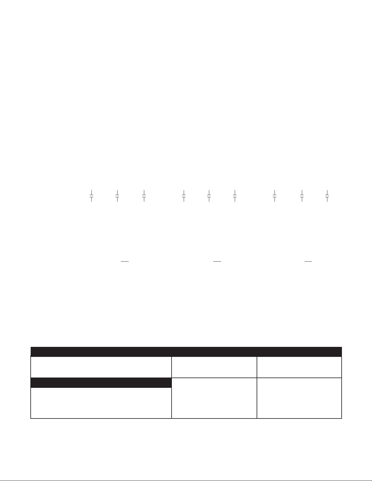
Effective December 2005 (date code M05) there are important changes to single-phase
motors. They now have a built-in, on-winding overload. They also require different start
and run capacitors in the control panel than old motors. Please read the information on panel wiring
and capacitor changes that are required to operate a new pump on an old control panel.
Grinder Pumps
1Ø and 3Ø, 1¼" Discharge
INSTALLATION, OPERATION AND TROUBLESHOOTING MANUAL
Page 2

Owner’s Information
Owner’s Information
Pump Model Number:
Pump Serial Number:
Pump Options (see Nomenclature):
• Seal Fail (Moisture) Sensor
• Pilot Duty Thermal Sensor
Control Model Number:
Dealer:
Dealer Phone No.
Date of Purchase: Installation:
Current Readings at Startup:
1Ø 3Ø L1-2 L2-3 L3-1
Amps: Amps:
Volts: Volts:
Table of Contents
Table of Contents
SUBJECT PAGE
Safety Instructions ...................................................................3
Pre-Installation Checks ...........................................................3
Lifting of Pump ....................................................................... 3
Optional Guide Rail or Lift-Out System ................................ 3
Piping ......................................................................................4
Wiring and Grounding............................................................4
Selecting and Wiring Pump Control Panels and Switches ...4-5
Installation ............................................................................... 5
Operation .............................................................................5-6
Float Switch and Panel Chart .................................................6
Three Phase Power Unbalance ................................................ 7
Insulation Resistance Readings ...............................................7
Engineering Data ....................................................................8
Typical Installations ................................................................. 9
Trouble Shooting ...................................................................10
Limited Warranty ..................................................................12
2
Page 3
DANGER
WARNING
CAUTION
WARNING
WARNING
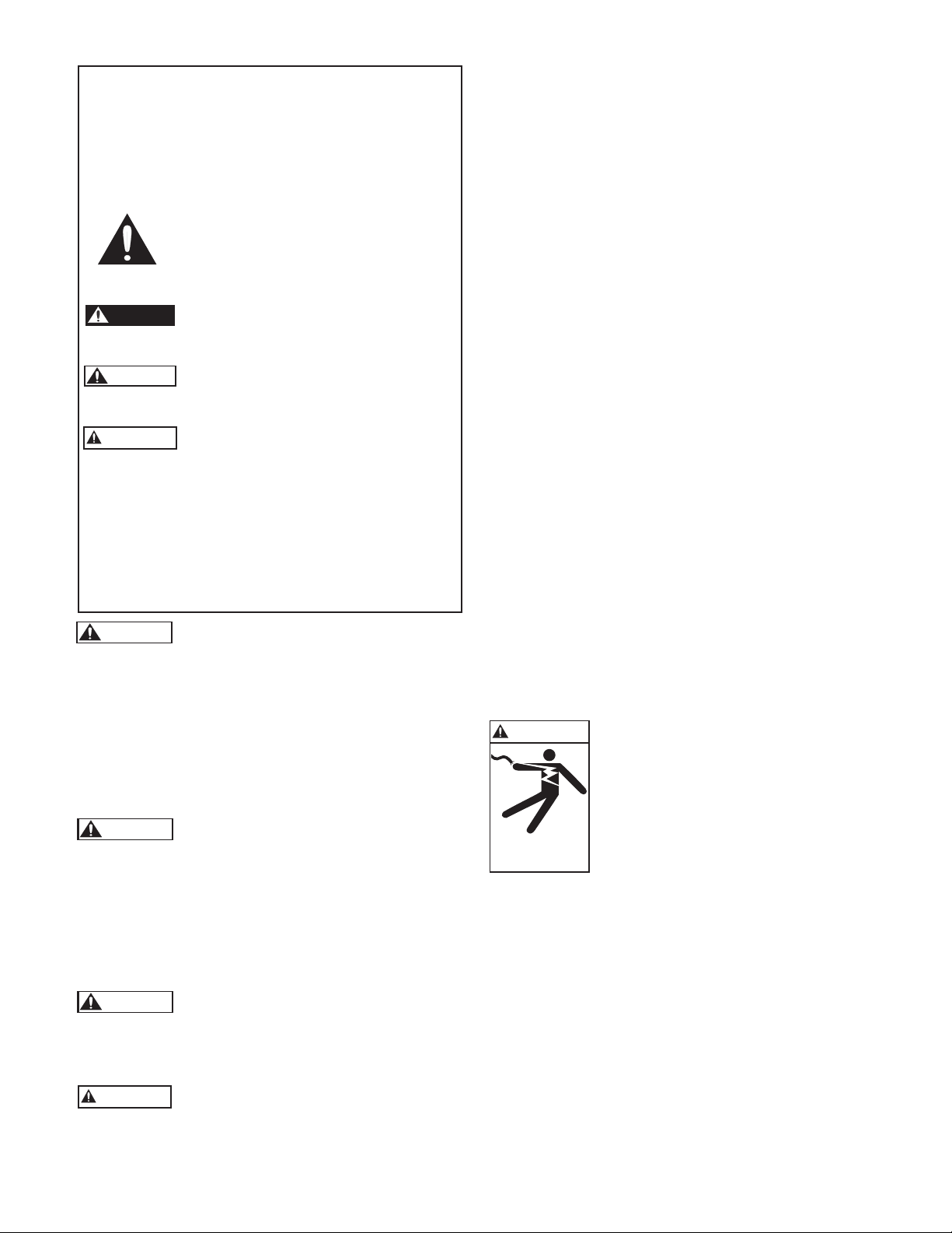
Hazardous voltage
can shock, burn or
cause death.
WARNING
WARNING
CAUTION
SAFETY INSTRUCTIONS
TO AVOID SERIOUS OR FATAL PERSONAL INJURY
OR MAJOR PROPERTY DAMAGE, READ AND
FOLLOW ALL SAFETY INSTRUCTIONS IN MANUAL
AND ON PUMP.
THIS MANUAL IS INTENDED TO ASSIST IN THE
INSTALLATION AND OPERATION OF THIS UNIT
AND MUST BE KEPT WITH THE PUMP.
This is a SAFETY ALERT SYMBOL. When
you see this symbol on the pump or in the
manual, look for one of the following signal
words and be alert to the potential for
personal injury or property damage.
Warns of hazards that WILL cause serious
personal injury, death or major property
damage.
Warns of hazards that CAN cause serious
personal injury, death or major property
damage.
Warns of hazards that CAN cause personal
injury or property damage.
NOTICE: INDICATES SPECIAL INSTRUCTIONS
WHICH ARE VERY IMPORTANT AND
MUST BE FOLLOWED.
THOROUGHLY REVIEW ALL INSTRUCTIONS AND
WARNINGS PRIOR TO PERFORMING ANY WORK
ON THIS PUMP.
MAINTAIN ALL SAFETY DECALS.
All electrical work must be performed by
a qualied technician. Always follow the
National Electrical Code (NEC), or the Canadian Electrical
Code, as well as all local, state and provincial codes. Code
questions should be directed to your local electrical inspector.
Failure to follow electrical codes and OSHA safety standards
may result in personal injury or equipment damage. Failure to
follow manufacturer’s installation instructions may result in
electrical shock, re hazard, personal injury or death, damaged
equipment, provide unsatisfactory performance, and may void
manufacturer’s warranty.
Standard units are not designed for use in
swimming pools, open bodies of water,
hazardous liquids, or where ammable gases exist. These
uids and gases may be present in containment areas. Tank or
wetwell must be vented per local codes.
Only pumps specically Listed for Class 1, Division 1 are allowable in hazardous liquids and where ammable gases may
exist. See specific pump catalog bulletins or pump nameplate
for all agency Listings.
Disconnect and lockout electrical power
before installing or servicing any electrical equipment. Many pumps are equipped with automatic
thermal overload protection which may allow an overheated
pump to restart unexpectedly.
All three phase (3Ø) control panels for
submersible pumps must provide
Class 10, quick-trip, overload protection.
PRE-INSTALLATION CHECKS
PRE-INSTALLATION CHECKS
Open all cartons and inspect for shipping damage. Report any
damage to your supplier or shipping carrier immediately.
Important: Always verify that the pump nameplate Amps,
Voltage, Phase, and HP ratings match your control panel and
power supply.
Many of our sewage pumps are oil-lled. If there are any signs
of oil leakage or if the unit has been stored for an extended
period check the oil level in the motor dome and the seal
housing, if so equipped.
Check the motor cover oil level through the pipe plug on top
of the unit. The motor chamber oil should just cover the motor. Do not overll, leave room for expansion!
To check the seal housing oil level, where used, lay the unit on
its side with the ll plug at 12 o’clock. Remove the plug. The
oil should be within ½" (13mm) of the top. If low, rell with
an ASTM 150 turbine oil. Replace the plug.
Oil is available in 5 gallon cans through our distributors. You
can also source oil locally at motor repair shops. Typical oil
brands are: Shell Turbo 32, Sunoco Sunvis 932, Texaco Regal
R&O 32, Exxon Nuto 32 and Mobil DTE Light.
Check the strain relief nut on power cable strain assemblies.
Power cables should be torqued to 75 in. lbs. for #16 cables
and 80 in. lbs. for all other cable assemblies. Seal/heat sensor
cables, where used, should be torqued to 75 in. lbs.
Warranty does not cover damage caused by connecting
pumps and controls to an incorrect power source (voltage/
phase supply).
Attach the extra label supplied with the pump to this manual
and record the model numbers and serial numbers from
the pumps and control panel on the front of this instruction
manual for future reference. Give it to the owner or afx it to
the control panel when nished with the installation.
LIFTING OF PUMP
LIFTING OF PUMP
DO NOT LIFT, CARRY OR HANG
PUMP BY THE ELECTRICAL
CABLES. DAMAGE TO THE
ELECTRICAL CABLES CAN CAUSE
SHOCK, BURNS OR DEATH.
Lift the pump with an adequately sized chain or cable attached
to the lifting eye bolt. DO NOT damage electrical and sensor
cables while raising and lowering unit.
OPTIONAL GUIDE RAIL/
OPTIONAL GUIDE RAIL/
BASE ELBOW SYSTEM
BASE ELBOW SYSTEM
In many efuent and sewage basins or lift stations it is
advisable to install the pump on a guide rail system to facilitate
installation and removal for inspection and/or service. Most
codes do not allow personnel to enter a wetwell without the
correct protective equipment and training. Guide rails are
designed to allow easy removal of the pump without the need
for entry into the wetwell or need to disturb piping. The guide
rail should locate the pump opposite the inuent opening
preventing stagnate areas where solids can settle. The basin or
pit must be capable of supporting the weight of the pump and
guide rail. The pit oor must be at.
3
Page 4
NOTICE: FOLLOW THE INSTRUCTIONS THAT ARE
WARNING
WARNING
WARNING
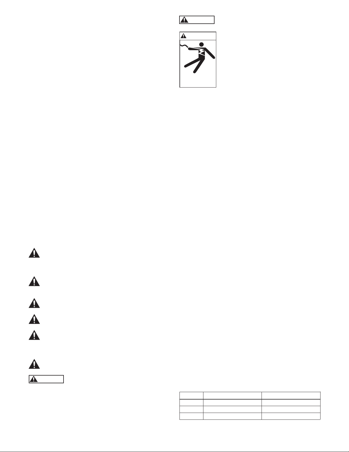
Hazardous voltage
can shock, burn or
cause death.
PIPING
PIPING
Discharge piping should be no smaller than the pump discharge diameter and kept as short as possible, avoiding unnecessary ttings to minimize friction losses.
Install a check valve to prevent uid backow. Backow
can allow the pump to “turbine” backwards and may cause
premature seal and/or bearing wear. If the pump is turning
backwards when it is called on to start the increased torque
may cause damage to the pump motor and/or motor shaft and
some single-phase pumps may actually run backwards.
Install an adequately sized gate valve after the check valve for
pump, plumbing and check valve maintenance.
Important – Before pump installation. Drill a 3⁄16" (4.8mm)
relief hole in the discharge pipe. It should be located within
the wetwell, 2" (51mm) above the pump discharge but below
the check valve. The relief hole allows any air to escape from
the casing. Allowing liquid into the casing will insure that the
pump can start when the liquid level rises. Unless a relief hole
is provided, a bottom intake pump could “air lock” and will
not pump water even though the impeller turns.
All piping must be adequately supported, so as not to impart
any piping strain or loads on the pump.
The pit access cover must be of sufcient size to allow for
inspection, maintenance and crane or hoist service.
WIRING AND GROUNDING
WIRING AND GROUNDING
Important notice: Read Safety Instructions before proceeding
with any wiring.
PROVIDED WITH THE GUIDE RAIL
ASSEMBLY.
Use only stranded copper wire to pump/motor and
ground. The ground wire must be at least as large as the
power supply wires. Wires should be color coded for
ease of maintenance and troubleshooting.
Install wire and ground according to the National Electrical Code (NEC), or the Canadian Electrical Code, as
well as all local, state and provincial codes.
Install an all leg disconnect switch where required by
code.
Disconnect and lockout electrical power before performing any service or installation.
The electrical supply voltage and phase must match all
equipment requirements. Incorrect voltage or phase can
cause re, motor and control damage, and voids the
warranty.
All splices must be waterproof. If using splice kits follow
manufacturer’s instructions.
Select the correct type and NEMA grade
junction box for the application and location.
The junction box must insure dry, safe wiring
connections.
Seal all controls from gases present which
may damage electrical components.
FAILURE TO PERMANENTLY
GROUND THE PUMP, MOTOR AND
CONTROLS BEFORE CONNECTING
TO POWER CAN CAUSE SHOCK,
BURNS OR DEATH.
ON NON-PLUG UNITS, DO NOT REMOVE CORD AND STRAIN RELIEF. DO
NOT CONNECT CONDUIT TO PUMP.
SELECTING AND WIRING
SELECTING AND WIRING
PUMP CONTROL PANELS
PUMP CONTROL PANELS
Control panel wiring diagrams are shipped with the
control panels. Please use the control panel drawings in
conjunction with this instruction manual to complete the
wiring.
Important – Read Before Proceeding
Single-Phase Motor Design Change Information –
Only for New Pump Installed on Older Panel.
Overload and Capacitors: Single-phase pumps built after
Dec.1, 2005 (M05 date code) now feature a built-in, on
winding overload. If replacing a pre-Dec 2005 pump (date
code L05 or earlier) you have to change the capacitors in the
old style control panel.
Pilot Duty Thermal Sensor/Overload Wire: Pre-Dec 2005
single-phase pumps had a pilot-duty thermal sensor wire
connected between the pump and an overload heater block in
the control panel, you will have to install a jumper wire across
the two high temperature/overload terminals when installing
a new pump on an old panel or the new pump may not operate.
Standard single-phase pumps no longer have a Pilot Duty
Thermal Sensor Wire but it is available as an option. Another
option is a Seal Fail Sensor & Wire. Please use the Nomenclature data found in this manual and the pump Order Number
to determine which optional features are on the pump being
installed.
CONTROL PANEL REQUIREMENTS
Single Phase Control Panels – Eff. Dec. 2005, M05 date code,
Series 1GD and 12GDS single phase grinder pumps require a
control panel containing as a minimum:
• Magnetic contactor
• Start capacitor
• Run capacitor
• Start relay
• Terminal wiring strip for all external connections.
See Recommended Panel Chart in Engineering Data Section
Capacitor and Starting Relay Information
Description Order a CP1GDB for New Pump Part Order No. – Old Pump
Start Cap 216-259 Mfd @ 330 vac RB-61 (594 Mfd @ 125 vac)
Run Cap 50 Mfd @ 370 vac RB-62 (30 Mfd @ 370 vac)
Start Relay 9K458 (RVA2ALKL) 9K458 or RB-60 (155031 102)
4
Page 5

Three Phase Control Panels
Series 1GD and 12GDS three phase grinder pumps require a
control panel containing as a minimum:
• A 3 pole circuit breaker.
• Magnetic starter with ambient compensated Class 10
overloads.
• Transformer to supply 115 or 24 volt control power.
• Terminal wiring strip for all external connections.
RECOMMENDED CONTROL PANEL AND
PUMP OPTIONS
• A panel seal failure circuit with relay and warning device can
only be used if pump is equipped with a seal failure sensor.
• High level alarm circuit
• Visual and/or audible high level alarm device.
Our Simplex and Duplex “Single Phase Grinder Panels” (see
the price book) contain built-in capacitors, a start relay and
wiring terminals.
In the event you wish to source a control panel locally we sell
capacitor kits which a panel shop will be able to build into a
custom panel. Note: the kits contain the capacitors and start
relay. These are not a eld installable, add-on item. Building
the capacitor kits into a control panel is a job for a UL or CSA
approved panel shop. Due to concern for liability, installer
safety and Agency Listing, our Customer Service technicians
are forbidden to assist anyone attempting to eld modify a
standard control panel using these capacitor kits. We hope you
understand and respect our position in this matter. “Recommended Control Panels” are listed in the Product Bulletins
found in the respective product catalog or on the website
named on the front cover of this IOM.
Motor High Temperature Sensor:
The single phase 1GD or 12GDS pumps have an optional
feature, a built-in motor high temperature sensor. This heat
sensor opens and closes the circuit to the contactor coil when
properly wired into a control panel. It opens at a motor temperature of 275°F (135°C) and stops the pump. As the motor
temperature drops to 112°F (78°C) the motor automatically
restarts.
Pump Seal Failure (Moisture Detection) Sensor:
An option on the 1GD and standard on the 12GDS. This
sensor located in the seal chamber detects the presence of
moisture in the seal chamber. When connected to an optional
seal failure relay and warning device in the control panel it
signals that service needs to be performed on the lower seal.
The seal failure circuit option must be ordered as a control
panel option, it is not supplied as a standard item.
FLOAT SWITCH TYPES
There are two basic oat switch designs; single-action and
wide-angle. Single-action switches operate over a range of 15º
so they open and close quickly. Wide-angle oats operate over
a 90º swing with the tether length between the oat body and
the pivot point controlling the On-Off range. The design determines how many oats are required with different systems
or controls.
Floats may be normally open (NO) for pump down applications or to empty a tank. Normally closed (NC) switches are
used to pump up or to ll a tank.
A control switch may be used only with a control panel, never
direct connected to a pump.
SETTING THE FLOAT SWITCHES
There are no absolute rules for where to set the oat switches,
it varies from job to job.
Suggested Rules to Follow:
All floats should be set below the Inlet pipe!
Off Float: Best: set so the water level is always above the top
of the pump (motor dome). Next Best: set so the water level is
not more than 6" below the top of the pump.
On Float: set so the volume of water between the On and Off
oats allows two (2) HP and larger pumps to run a minimum
of 2 minutes. Basin literature states the gallons of storage per
inch of basin height.
Lag/Alarm Float(s): should be staggered above the Off and
On oats. Try to use most of the available storage provided
by the basin, save some space for reserve storage capacity. See
Diagrams and Charts in Float Switch Chart Section.
PANEL WIRING DIAGRAMS
Our control panels are shipped with instructions and wiring diagrams. Use those instructions in conjunction with this
IOM. Electrical installation should be performed only by
qualied technicians. Any problem or questions pertaining to
another brand control must be referred to that control supplier or manufacturer. Our technical people have no technical
schematics or trouble shooting information for other companies' controls.
ALARMS
We recommend the installation of an alarm on all Wastewater pump installations. Many standard control panels come
equipped with alarm circuits. If a control panel is not used,
a stand alone high liquid level alarm is available. The alarm
alerts the owner of a high liquid level in the system so they can
contact the appropriate service personnel to investigate the
situation.
5
Page 6

INSTALLATION
INSTALLATION
Connect the pump(s) to the guide rail pump adapters or to the
discharge piping. Guide rail bases should be anchored to the
wetwell oor.
Complete all wiring per the control panel wiring diagrams
and NEC, Canadian, state, provincial and/or local codes.
This a good time to check for proper rotation of the
motors/impellers.
!
DANGER
DO NOT PLACE HANDS IN PUMP
SUCTION WHILE CHECKING
MOTOR ROTATION. TO DO SO WILL
CAUSE SEVERE PERSONAL INJURY.
Always verify correct rotation. Correct
rotation is indicated on the pump casing.
Three phase motors are reversible. It is
Hazardous Machinery
allowable to bump or jog the motor for a
few seconds to check impeller rotation. It
is easier to check rotation before installing
the pump. Switch any two power leads to
reverse rotation.
Lower the pump(s) into the wetwell.
Check to insure that the oats will operate freely and not
contact the piping.
OPERATION
OPERATION
Once the piping connections are made and checked you can
run the pumps.
Control Panel Operation – Fill the wetwell with clear water.
Use the pump H-O-A (Hand-Off-Automatic) switches
in Hand to test the pumps. If they operate well in Hand
proceed to test Automatic operation. If the pumps run but
fail to pump, they are probably air locked, drill the relief holes
per the instructions in the Piping Section.
Place Control Panel switch(es) in Automatic position and
thoroughly test the operation of the ON, OFF, and
Alarm oats by lling the wetwell with clear water.
Important: Failure to provide a Neutral from the power
supply to a 1Ø, 230 volt Control Panel will not allow the
panel control circuit to operate. The Neutral is necessary
to complete the 115 volt control circuit.
Check voltage and amperage and record the data on the front
of this manual for future reference. Compare the amperage
readings to the pump nameplate maximum amperage. If
higher than nameplate amperage investigate cause. Operating
the pump off the curve, i.e. with too little head or with high
or low voltage will increase amperage. The motor will operate
properly with voltage not more than 10% above or below
pump nameplate ratings. Performance within this range will
not necessarily be the same as the published performance at
the exact rated nameplate frequency and voltage. Correct the
problem before proceeding. Three phase unbalance is also a
possible cause. See Three Phase Power Unbalance and follow
the instructions.
Reset the Alarm circuit, place pump switch(es) in the Automatic position and Control Switch in ON position. The
system is now ready for automatic operation.
Explain the operation of the pumps, controls and alarms to
the end user. Leave the paperwork with the owner or at the
control panel if in a dry, secure location.
NOMENCLATURE DESCRIPTION
1st, 2nd and 3rd Characters – Discharge Size and Type
1GD = 1¼" discharge, grinder, dual seal
4th Character – Mechanical Seals
5 = silicon carbide/silicon carbide/BUNA – lower seal and
carbon/ceramic/BUNA – upper seal (standard)
3 = silicon carbide/tungsten carbide/BUNA – lower seal
and carbon/ceramic/BUNA – upper seal (optional)
5th Character – Cycle/RPM
1 = 60 Hz/3500 RPM
5 = 50 Hz/2900 RPM
6th Character – Horsepower
G = 2 HP
7th Character – Phase/Voltage
1 = single phase, 230 V
2 = three phase, 200 V
3 = three phase, 230 V
4 = three phase, 460 V
5 = three phase, 575 V
6 = three phase, 380 V
8 = single phase, 208 V
8th Character – Impeller Diameter
A = 55⁄8", Standard C = 4¾"
B = 5¼" D = 4¼"
9th Character – Cord Length (Power and Sensor)
A = 20' (standard) G = 75'
D = 30' J = 100'
F = 50'
10th Character – Options
S = Seal fail, moisture sensing circuit
1
E = Epoxy paint
Last Character – Option
H = Pilot duty thermal sensors1
1
These options add a 2-wire or 4-wire sensor cord to the pump and
require optional control panel circuits to operate. See panel options
on control panel bulletin BCP5.
6
Page 7
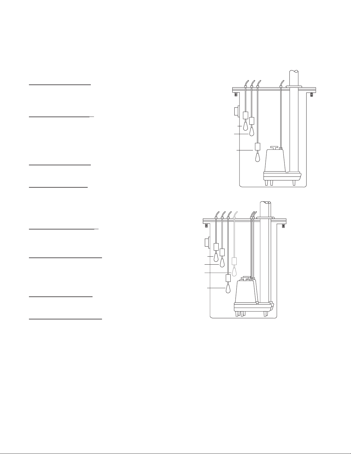
FLOAT SWITCH AND PANEL CHART
Inlet
Alarm SW3
Pump On SW2
Pump Off SW1
Discharge
FLOAT SWITCH AND PANEL CHART
The purpose of this chart is to show the required switch
quantities and the function of each switch in a typical
wastewater system. The quantities required vary depending on the switch type, single-action or wide-angle.
Switch quantities also vary by panel type: simplex with
and without alarms, and duplex with alarms.
Duplex Panels using single-action switches:
Three Float Panel Wiring
SW1 Bottom Pumps Off
SW2 Middle 1st Pump On
SW3 Top 2nd Pump & Alarm On
Four Float Panel Wiring ②
SW1 Bottom Pumps Off
SW2 2nd 1st Pump On
SW3 3rd 2nd Pump On
SW4 Top Alarm On
Duplex Panels using wide-angle switches:
Three Float Panel Wiring
SW1 Bottom 1st Pump On/Both Off
SW2 Top 2nd Pump & Alarm On
Four Float Panel Wiring
SW1 Bottom 1st Pump On/Both Off
SW2 Middle 2nd Pump On
SW3 Top Alarm On
Simplex ①
Discharge
Simplex Panel using single-action switches:
Simplex Panel with Alarm ①
SW1 Bottom Pump Off
SW2 Middle Pump On
SW3 Top Alarm On/Off
Simplex Panel with No Alarm
SW1 Bottom Pump Off
SW2 Top Pump On
Simplex Panel using wide-angle switches:
Simplex Panel with Alarm
SW1 Bottom Pump On/Off
SW2 Top Alarm On/Off
Simplex Panel with No Alarm
SW1 Pump On/Off
Inlet
Alarm SW4
Lag Pump On
SW3
Lead Pump On
SW2
Pump Off
SW1
Duplex ②
7
Page 8
THREE PHASE POWER UNBALANCE
THREE PHASE POWER UNBALANCE
A full three phase supply consisting of three individual
transformers or one three phase transformer is recommended. “Open” delta or wye connections using only
two transformers can be used, but are more likely to
cause poor performance, overload tripping or early motor failure due to current unbalance.
Check the current in each of the three motor leads and
calculate the current unbalance as explained below.
If the current unbalance is 2% or less, leave the leads as
connected.
If the current unbalance is more than 2%, current
readings should be checked on each leg using each of the
three possible hook-ups. Roll the motor leads across the
starter in the same direction to prevent motor reversal.
To calculate percent of current unbalance:
A. Add the three line amp values together.
B. Divide the sum by three, yielding average current.
C. Pick the amp value which is furthest from the average
current (either high or low).
D. Determine the difference between this amp value
(furthest from average) and the average.
E. Divide the difference by the average. Multiply the
result by 100 to determine percent of unbalance.
Current unbalance should not exceed 5% at service
factor load or 10% at rated input load. If the unbalance
cannot be corrected by rolling leads, the source of the
unbalance must be located and corrected. If, on the three
possible hookups, the leg farthest from the average stays
on the same power lead, most of the unbalance is coming
from the power source.
Contact your local power company to resolve the
imbalance.
Hookup 1 Hookup 2 Hookup 3
Starter Terminals L1 L2 L3 L1 L2 L3 L1 L2 L3
Motor Leads R B W W R B B W R
T3 T1 T2 T2 T3 T1 T1 T2 T3
Example:
T3-R = 51 amps T2-W = 50 amps T1-B = 50 amps
T1-B = 46 amps T3-R = 48 amps T2-W = 49 amps
T2-W = 53 amps T1-B = 52 amps T3-R = 51 amps
Total = 150 amps Total = 150 amps Total = 150 amps
÷ 3 = 50 amps ÷ 3 = 50 amps ÷ 3 = 50 amps
— 46 = 4 amps — 48 = 2 amps — 49 = 1 amps
4 ÷ 50 = .08 or 8% 2 ÷ 50 = .04 or 4% 1 ÷ 50 = .02 or 2%
INSULATION RESISTANCE READINGS
INSULATION RESISTANCE READINGS
Normal Ohm and Megohm Values between all leads and ground
Condition of Motor and Leads Ohm Value Megohm Value
A new motor (without drop cable). 20,000,000 (or more) 20 (or more)
A used motor which can be reinstalled in well. 10,000,000 (or more) 10 (or more)
Motor in well. Readings are for drop cable plus motor.
New motor. 2,000,000 (or more) 2 (or more)
Motor in good condition. 500,000 - 2,000,000 .5 - 2
Insulation damage, locate and repair. Less than 500,000 Less than .5
Insulation resistance varies very little with rating. Motors of all HP, voltage and phase ratings have similar values
of insulation resistance.
Insulation resistance values above are based on readings taken with a megohmmeter with a 500V DC output.
Readings may vary using a lower voltage ohmmeter, consult factory if readings are in question.
This table was reprinted through the courtesy of Franklin Electric.
8
Page 9
ENGINEERING DATA
L1
L2
L3
GRD
S1
Red
Black
White
Green
PUMP
ENGINEERING DATA
Engineering data for specific models may be found in your catalog and on our website (address is on the cover).
PUMP OPERATION GUIDELINES
Minimum Submergence
Continuous
Duty
Intermittent
Duty
RECOMMENDED 1Ø CONTROL PANELS
RECOMMENDED 1Ø CONTROL PANELS
Effective with December 2005 (M05) Date Codes -
Single-Phase 1GD Pumps Contain a Built-in,
Auto Reset Overload.
Important Control Panel Requirements and Notes:
1) See panel bulletin BCP5 for other available options.
2) These pumps require a magnetic contactor, start and run capacitors
and a starting relay in the control panel.
3) CP-1GDB Capacitor packs with starting relays are available on
product bulletin BCPCAP. They are for certified panel shops to “build” into a custom panel. Field installing capacitor packs into a S10020 or D10020 will negate
the UL listing on that panel and is therefore not permissable.
Fully Submerged
6" Below Top of Motor
Pump Pump Seal Voltage Recommended Control Panel
Order No. Fail Circuit / Phase Simplex Duplex
1GD51G1A_ NO 230 / 1 S1GD2 D1GD2
1GD51G8A_ NO 208 / 1 S1GD2 D1GD2
1GD51G1A_S YES 230 / 1 S1GD2H D1GD2J
1GD51G8A_S YES 208 / 1 S1GD2H D1GD2J
Continuous
Operation
Intermittent
Operation
Maximum Fluid Temperature
104º F 40º C
140º F 60º C
PANEL CAPACITOR WIRING DIAGRAMS
PANEL CAPACITOR WIRING DIAGRAMS
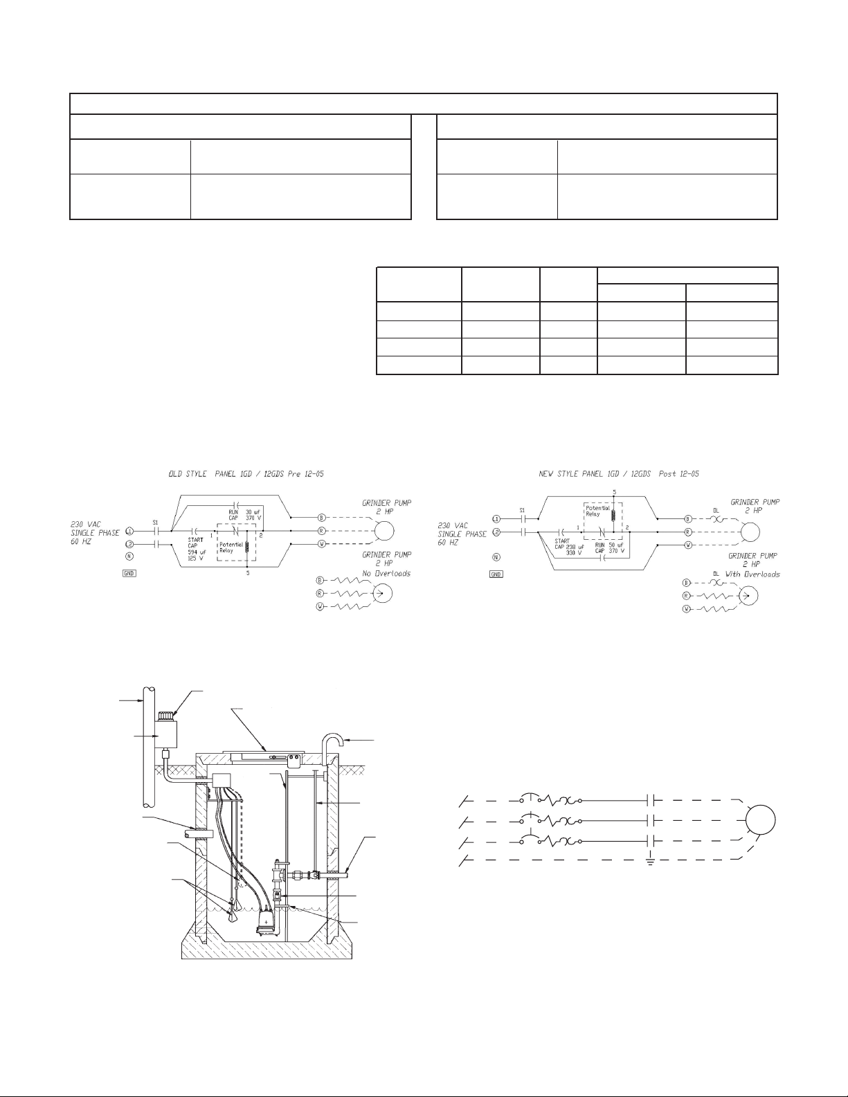
TYPICAL PLUMBING AND INSTALLATION
TYPICAL PLUMBING AND INSTALLATION
SERVICE
POLE
CONTROL
PANEL
INLET GROMMET
FLOAT SWITCH
HIGH LEVEL ALARM
(OPTIONAL)
FLOAT SWITCH
ALARM LIGHT
HINGED ACCESS DOOR
GUIDE
RAIL
VENT
VALVE
OPERATING
ROD
DISCHARGE
CHECK VALVE
LOWER
PUMP GUIDE
Typical Three Phase Connection Diagram
Fig. 2
Fig. 1
9
Page 10

WARNING
Hazardous
voltage
TROUBLESHOOTING
TROUBLESHOOTING
FAILURE TO DISCONNECT AND LOCKOUT ELECTRICAL
POWER BEFORE ATTEMPTING ANY SERVICE CAN CAUSE
SHOCK, BURNS OR DEATH.
SYMPTOM PROBABLE CAUSE RECOMMENDED ACTION
MOTOR NOT RUNNING Motor thermal protector tripped. Allow motor to cool. Insure minimum pump
submergence. Clear debris from casing and impeller.
NOTE: If circuit breaker
“OPENS” repeatedly,
Open circuit breaker or blown fuse. Determine cause, call a qualied electrician.
DO NOT reset. Call
Pump impeller binding or jammed. Check motor amp draw. If two or more times higher
qualied electrician.
than listed on pump nameplate, impeller or cutter is
a) Manual operation Power cable is damaged. locked, motor bearings or shaft is damaged. Clear
Inadequate electrical connection debris from cutter casing and impeller, consult with
in control panel.
Resistance between power leads and ground should
b) Automatic operation No neutral wire read innity. If any reading is incorrect, call a
connected to control panel. qualied electrician.
Inadequate electrical connection Inspect control panel wiring. Call a qualied
in control panel. electrician.
Defective liquid level switch. With switch disconnected, check continuity while
NOTE: Check the pump in
activating liquid level switch. Replace switch, as
manual mode first to confirm
required.
operation. If pump operates,
Insufcient liquid level to Allow liquid level to rise 3" to 4" (76 mm - 101 mm)
the automatic control or
activate controls. above turn-on level.
wiring is at fault. If pump
Liquid level cords tangled. Untangle cords and insure free operation.
does not operate, see above.
PUMP WILL NOT Liquid level cords tangled. Untangle cords and insure free operation.
TURN OFF
Pump is air locked. Shut off pump for approximately one minute, then
restart. Repeat until air lock clears. If air locking
persists in a system with a check valve, a 3⁄16" (4.8 mm)
hole may be drilled in the discharge pipe approximately
2" (51 mm) above the discharge connection.
dealer.
Inuent ow is matching pump’s Larger pump may be required.
discharge capacity.
LITTLE OR NO LIQUID Check valve installed backwards, Check ow arrow on valve and check valve
DELIVERED BY PUMP plugged or stuck closed. operation.
Excessive system head. Consult with dealer.
Pump inlet plugged. Inspect and clear as required.
Improper voltage or wired Check pump rotation, voltage and wiring.
incorrectly. Consult with qualied electrician.
Pump is air locked. See recommended action, above.
Impeller is worn or damaged. Inspect impeller, replace as required.
Liquid level controls defective Inspect, readjust or replace as required.
or improperly positioned.
PUMP CYCLES Discharge check valve inoperative. Inspect, repair or replace as required.
CONSTANTLY
Sewage containment area too small. Consult with dealer.
Liquid level controls defective or Inspect, readjust or replace as required.
improperly positioned.
Inuent excessive for this size Consult with dealer.
pump.
10
Page 11

NOTES
NOTES
11
Page 12

GOULDS WATER TECHNOLOGY LIMITED WARRANTY
This warranty applies to all water systems pumps manufactured by Goulds Water Technology.
Any part or parts found to be defective within the warranty period shall be replaced at no charge to the dealer during the warranty period. The warranty period shall exist for
a period of twelve (12) months from date of installation or eighteen (18) months from date of manufacture, whichever period is shorter.
A dealer who believes that a warranty claim exists must contact the authorized Goulds Water Technology distributor from whom the pump was purchased and furnish com-
plete details regarding the claim. The distributor is authorized to adjust any warranty claims utilizing the Goulds Water Technology Customer Service Department.
The warranty excludes:
(a) Labor, transportation and related costs incurred by the dealer;
(b) Reinstallation costs of repaired equipment;
(c) Reinstallation costs of replacement equipment;
(d) Consequential damages of any kind; and,
(e) Reimbursement for loss caused by interruption of service.
For purposes of this warranty, the following terms have these definitions:
(1) “Distributor” means any individual, partnership, corporation, association, or other legal relationship that stands between Goulds Water Technology and the dealer in
purchases, consignments or contracts for sale of the subject pumps.
(2) “Dealer” means any individual, partnership, corporation, association, or other legal relationship which engages in the business of selling or leasing pumps to customers.
(3) “Customer” means any entity who buys or leases the subject pumps from a dealer. The “customer” may mean an individual, partnership, corporation, limited liability
company, association or other legal entity which may engage in any type of business.
THIS WARRANTY EXTENDS TO THE DEALER ONLY.
Xylem, Inc.
2881 East Bayard Street Ext., Suite A
Seneca Falls, NY 13148
Phone: (866) 325-4210
Fax: (888) 322-5877
www.xyleminc.com/brands/gouldswatertechnology
Goulds is a registered trademark of Goulds Pumps, Inc. and is used under license.
© 2012 Xylem Inc. IM039 Revision Number 4 July 2012
Page 13

MANUAL DE INSTRUCCIÓN
ADVERTENCIA
IM039
A partir de diciembre de 2005 (código de fecha M05) se encuentran en vigencia importantes
cambios en los motores monofásicos. Ahora poseen una sobrecarga de cableado incorporado. Además requieren condensadores de arranque y funcionamiento en el panel de control diferentes de
los motores antiguos. Lea la información acerca del cableado del panel y los cambios de condensadores
que se necesitan para hacer funcionar una bomba nueva con un panel de control antiguo.
Bombas trituradoras
Monofásicas y trifásicas, descarga de 1¼ pulg.
MANUAL DE INSTALACIÓN, OPERACIÓN E IDENTIFICACIÓN Y RESOLUCIÓN DE PROBLEMAS
Page 14

Información del propietario
Número de modelo de la bomba:
Número de serie de la bomba:
Opciones de la bomba (vea Nomenclatura)
• Sensor de falla del sello (detección de humedad)
• Sensor piloto de alta temperatura de servicio
Número de modelo del control:
Agente:
No. telefónico del agente:
Fecha de compra: Instalación:
Lecturas actuales en el momento de la puesta en marcha:
1Ø 3Ø L1-2 L2-3 L3-1
Amperios: Amperios:
Voltios: Voltios:
ÍndiceInformación del propietario
Índice
TEMA PÁGINA
Instrucciones de seguridad ............................................15
Vericaciones preliminares a la instalación....................15
Levantamiento de la bomba ..........................................15
Riel de guía o sistema de levantamiento opcional .........15
Tuberías ........................................................................16
Alambrado y conexión a tierra .....................................16
Selección y cableado de los interruptores y
paneles de control de la bomba .......................... 16-17
Instalación ....................................................................17
Operación .............................................................. 17-18
Tabla del panel e interruptores de otador ....................18
Desbalance de potencia trifásica ...................................19
Lecturas de resistencia de aislamiento ...........................19
Datos de ingeniería .......................................................20
Instalaciones típicas ......................................................21
Identicación y resolución de problemas ......................22
Garantía limitada ..........................................................24
14
Page 15

INSTRUCCIONES DE SEGURIDAD
PELIGRO
ADVERTENCIA
PRECAUCIÓN
ADVERTENCIA
Un voltaje peligroso puede
producir golpes el ctricos,
quemaduras o la muerte.
PRECAUCIÓN
PARA EVITAR LESIONES PERSONALES GRAVES O
AÚN FATALES Y SERIOS DAÑOS MATERIALES, LEA
Y SIGA TODAS LAS INSTRUCCIONES DE SEGURIDAD EN EL MANUAL Y EN LA BOMBA.
ESTE MANUAL HA SIDO CREADO COMO UNA
GUÍA PARA LA INSTALACIÓN Y OPERACIÓN DE
ESTA UNIDAD Y SE DEBE CONSERVAR JUNTO A
LA BOMBA.
AVISO: INDICA INSTRUCCIONES ESPECIALES
QUE SON MUY IMPORTANTES Y QUE SE
DEBEN SEGUIR.
EXAMINE BIEN TODAS LAS INSTRUCCIONES Y
ADVERTENCIAS ANTES DE REALIZAR CUALQUIER TRABAJO EN ESTA BOMBA.
MANTENGA TODAS LAS CALCOMANÍAS DE
SEGURIDAD.
Código Eléctrico de EE.UU. (NEC) o el Código Eléctrico
Canadiense, además de todos los códigos locales, estatales y
provinciales. Las preguntas acerca del código deben ser dirigidas al inspector eléctrico local. Si se hace caso omiso a los códigos eléctricos y normas de seguridad de OSHA, se pueden
producir lesiones personales o daños al equipo. Si se hace
caso omiso a las instrucciones de instalación del fabricante, se
puede producir electrochoque, peligro de incendio, lesiones
personales o aún la muerte, daños al equipo, rendimiento
insatisfactorio y podría anularse la garantía del fabricante.
agua, líquidos peligrosos o donde existan gases inamables.
Estos uidos y gases podrían estar presentes en áreas de contención. El tanque o pozo debe ser ventilado de acuerdo con
los códigos locales.
En lugares con líquidos inamables o donde pudiesen
pudiese haber gases inamables sólo deben usarse bombas
especícamente clasicadas para áreas de Clase 1, División
1. Consulte los boletines de catálogos de bombas específicas
o la placa de identificación de la bomba con respecto a las
listas de agencias.
eléctrico. Muchas bombas están equipadas con protección
automática contra la sobrecarga térmica, la cual podría permitir
que una bomba demasiado caliente rearranque inesperadamente.
ADVERTENCIA
ADVERTENCIA
ADVERTENCIA
Éste es un SÍMBOLO DE ALERTA DE
SEGURIDAD. Cuando vea este símbolo
en la bomba o en el manual, busque una
de las siguientes palabras de señal y esté
alerta a la probabilidad de lesiones
personales o daños materiales.
Advierte los peligros que CAUSARÁN
graves lesiones personales, la muerte o
daños materiales mayores.
Advierte los peligros que PUEDEN causar
graves lesiones personales, la muerte o
daños materiales mayores.
Advierte los peligros que PUEDEN causar
lesiones personales o daños materiales.
Todo el trabajo eléctrico debe ser realizado
por un técnico calicado. Siempre siga el
Las unidades estándar no están diseñadas
para usarse en albercas, masas abiertas de
Desconecte y bloquee la corriente eléctrica antes
de instalar o dar servicio a cualquier equipo
Todos los paneles de control trifásicos (3Ø)
para bombas sumergibles deben incluir pro-
tección contra sobrecarga de Clase 10, de disparo rápido.
VERIFICACIONES PRELIMINARES
VERIFICACIONES PRELIMINARES
A LA INSTALACIÓN
A LA INSTALACIÓN
Abra todas las cajas e inspeccione el equipo para determinar
si se ocasionaron daños durante el envío. Notique cualquier
daño a su proveedor o a la compañía de transporte de
inmediato.
Importante: Siempre verifique que las clasificaciones de
corriente, tensión, fase y potencia en la placa de identicación
de la bomba correspondan con las del panel de control y
fuente de alimentación.
Muchas de nuestras bombas para alcantarillado están llenas
con aceite. Si hay alguna señal de fuga de aceite o si la unidad
estuvo almacenada durante largo tiempo, verifique el nivel
de aceite en la cúpula del motor y la caja del sello, en caso de
haberla.
Verifique el nivel de aceite de la cubierta del motor a través
del tapón de la tubería en el extremo superior de la unidad.
El aceite en la cámara del motor debe cubrir apenas el motor.
¡No llene en exceso, deje espacio para expansión!
Para verificar el nivel de aceite de la caja del sello, en caso
que se use, coloque la unidad de lado con el tapón de llenado
en la posición de las 12:00 horas. Retire el tapón. El aceite
debe estar a menos de ½ pulg. (13 mm) del borde superior.
Si el nivel está bajo, agregue aceite para turbinas ASTM 150.
Reinstale el tapón.
Puede obtenerse aceite en latas de 5 galones de nuestros
distribuidores. También puede obtener aceite a nivel local en
talleres de reparación de motores. Las marcas típicas de aceite
son: Shell Turbo 32, Sunoco Sunvis 932, Texaco Regal R&O
32, Exxon Nuto 32 y Mobil DTE Light.
Inspeccione la tuerca de alivio de tensión en los conjuntos
de protección contra tirones de los cables de alimentación.
Torsión de los cables de alimentación: 75 pulg.-lbs. para
cables #16 y 80 pulg.-lbs. para todos los otros tipos de cable.
La torsión de los cables de sensores de sello/calor, cuando se
usen, debe ser de 75 pulg.-lbs.
La garantía no cubre daños causados por conectar bombas y
controles a la fuente de energía incorrecta (fuente de tensión/
fase).
Para futuras referencias, adhiera la etiqueta que se suministra con la bomba en el frente de este manual y registre los
números de modelos y los números de serie de las bombas
y del panel de control. Entregue el manual al propietario o
adjúntelo al panel de control una vez nalizada la instalación.
LEVANTAMIENTO DE LA BOMBA
LEVANTAMIENTO DE LA BOMBA
NO LEVANTE NI TRANSPORTE
NI CUELGUE LA BOMBA DE LOS
CABLES ELÉCTRICOS. EL DAÑO A
LOS CABLES ELÉCTRICOS PUEDE
PRODUCIR ELECTROCHOQUE,
QUEMADURAS O AÚN LA MUERTE.
Levante la bomba con una cadena o cable de tamaño adecuado
conectado al perno de ojo de levantamiento. NO dañe los
cables eléctricos o de los sensores al subir y bajar la unidad.
15
Page 16

ADVERTENCIA
ADVERTENCIA
RIEL GUÍA Y SISTEMA DE CODO
ADVERTENCIA
Un voltaje peligroso puede
producir golpes el ctricos,
quemaduras o la muerte.
RIEL GUÍA Y SISTEMA DE CODO
BASE OPCIONALES
BASE OPCIONALES
En muchos estanques de alcantarillado y euentes o estaciones de elevación se recomienda instalar la bomba en un
sistema de riel guía para hacer más fácil la instalación y la
extracción de la bomba y para realizar tareas de inspección
y/o de servicio. La mayoría de los códigos no permiten que el
personal ingrese a un pozo de sumidero sin el equipo de protección adecuada y sin estar convenientemente capacitados.
Los rieles guías están diseñados para permitir que la bomba se
extraiga con facilidad, sin necesidad de ingresar al pozo sumidero o desorganizar la tubería. El riel guía deberá ubicar la
bomba opuesta a la abertura del líquido entrante, evitando las
áreas estancadas donde se pueden asentar elementos sólidos.
El estanque o fosa debe ser capaz de soportar el peso de la
bomba y del riel guía. El piso de la fosa debe ser plano.
AVISO: SIGA LAS INSTRUCCIONES INCLUIDAS CON
TUBERÍAS
TUBERÍAS
La tubería de descarga no debe ser más pequeña que el
diámetro de descarga de la bomba y debe mantenerse lo
más corta posible, evitando los accesorios innecesarios para
reducir al mínimo las pérdidas por fricción.
Instale una válvula de retención para impedir el retroceso.
El contraujo puede hacer que la bomba “gire” en dirección
inversa, produciendo un desgaste prematuro del sello y/o
del cojinete. Si la bomba gira en sentido inverso al arrancar,
el aumento de torsión puede dañar el motor y/o el eje del
motor de la bomba y algunas bombas monofásicas hasta
podrían funcionar en sentido inverso.
Instale una válvula de compuerta de tamaño adecuado
despues de la válvula de retención para facilitar el mantenimiento de la bomba, las tuberías y la válvula de retención.
Importante – antes de instalar la bomba. Perfore un oricio
de alivio de 3⁄16 pulg. (4.8 mm) en la tubería de descarga.
Debe situarse dentro del pozo, a 2 pulg. (51 mm) sobre la
descarga de la bomba, pero debajo de la válvula de retención. El oricio de alivio permite el escape de aire de la
carcasa. Al permitir que entre líquido a la carcasa se asegura
que la bomba pueda arrancar cuando el nivel de líquido
aumente. A menos que se proporcione un oricio de alivio,
una bomba de toma inferior podría “obstruirse con aire” y
no bombear agua, a pesar de que el impulsor gire.
Todas las tuberías deben estar apoyadas correctamente, de
modo que no se apliquen esfuerzos o cargas de las tuberías a
la bomba.
La cubierta de acceso a la fosa debe ser de tamaño suciente
para permitir realizar el servicio de inspección, mantenimiento y levantamiento con grúa o montacargas.
CABLEADO Y CONEXIÓN A TIERRA
CABLEADO Y CONEXIÓN A TIERRA
Aviso importante: Lea las instrucciones de seguridad antes de
proseguir con el cableado.
16
EL CONJUNTO DEL RIEL DE GUÍA.
Use únicamente alambre trenzado de cobre para la
bomba/motor y la conexión a tierra. El alambre de
conexión a tierra debe ser al menos del mismo tamaño que los alambres de la fuente de alimentación. Los
alambres deben codicarse con colores para facilitar
el mantenimiento y la identicación y resolución de
problemas.
Instale los cables y la conexión a tierra de acuerdo con
el Código Eléctrico de EE.UU. (NEC) o el Código
Eléctrico Canadiense, además de los códigos locales,
estatales y provinciales.
Instale un desconectador de todos los circuitos donde el
código lo requiera.
Desconecte y bloquee la corriente eléctrica antes de
instalar o dar servicio.
La tensión y fase de la fuente de alimentación debe corresponder con todos los requerimientos del equipo. La
tensión o fase incorrecta puede producir incendio, daño
al motor o a los controles y anula la garantía.
Todos los empalmes debe ser impermeables. Si utiliza
juegos de empalme, siga las instrucciones del fabricante.
Seleccione una caja de conexiones NEMA del
tipo correcto para la aplicación y ubicación.
La caja de conexiones debe garantizar
conexiones de cableado seguras y secas.
Selle todos los controles de los gases presentes que pudiesen dañar los componentes
eléctricos.
LA FALLA DE CONECTAR A TIERRA
PERMANENTEMENTE LA BOMBA, EL
MOTOR Y LOS CONTROLES, ANTES DE CONECTAR LA CORRIENTE
ELÉCTRICA, PUEDE CAUSAR
ELECTROCHOQUE, QUEMADURAS O
LA MUERTE.
EN EL CASO DE UNIDADES SIN
ENCHUFE, NO QUITE EL CABLE NI
EL PROTECTOR CONTRA TIRONES.
NO CONECTE EL TUBO-CONDUCTO
A LA BOMBA.
SELECCIÓN Y CABLEADO DE LOS PANELES DE
SELECCIÓN Y CABLEADO DE LOS PANELES DE
CONTROL DE LA BOMBA
CONTROL DE LA BOMBA
Los diagramas de cableado del panel de control se
envían con los paneles de control. Por favor, utilice los
planos del panel de control junto con este manual de
instrucción para completar el cableado.
Importante – Lea antes de continuar
Información del cambio de diseño del motor
monofásico – Solamente para una bomba nueva
instalada en un panel antiguo.
Sobrecarga y condensadores: las bombas monofásicas
construidas después del 1 de diciembre de 2005
(código de fecha M05) ofrecen una sobrecarga de
cableado incorporado. Si reemplaza una bomba
anterior a diciembre de 2005 (código de fecha L05
o anterior) debe cambiar los condensadores en el
antiguo panel de control.
Cable de sobrecarga/sensor identicador de alta
temperatura de ciclo: las bombas monofásicas
anteriores a diciembre de 2005 contaban con un cable
sensor piloto de alta temperatura de ciclo conectado
entre la bomba y un bloque calentador de sobrecarga
en el panel de control. Tendrá que instalar un cable
de acoplamiento a través de las dos terminales de
alta temperatura y de sobrecarga cuando instale una
Page 17

bomba nueva en un panel antiguo o puede ocurrir que
la bomba nueva no funcione.
Las bombas monofásicas estándar ya no poseen un
cable sensor piloto de alta temperatura de ciclo pero
se encuentra disponible como elemento opcional.
Otra opción es un sensor de falla del sello y cable.
Utilice los datos de Nomenclatura que se encuentran
en este manual y el número de orden de la bomba
para determinar qué características opcionales se
encuentran en la bomba que está instalando.
REQUISITOS DEL PANEL DE CONTROL
Paneles de control monofásicos –Vigente a partir de diciembre de 2005, código de fecha M05, las bombas trituradoras
serie 1GD y 12 GDS requieren de un panel de control que,
como mínimo, contenga:
• Interruptor magnético.
• Condensador de arranque.
• Condensador de funcionamiento.
• Relé de arranque.
• Banda de conector de cableado para todas las conexiones
externas.
Vea el gráfico de panel recomendado en la sección Datos de
ingeniería.
Información del condensador y del relé de arranque
Descripción
para una bomba nueva Vieja bomba
Cond. de arranque 216-259 Mfd @ 330 vac RB-61 (594 Mfd @ 125 vac)
Cond. de funcionamiento 50 Mfd @ 370 vac RB-62 (30 Mfd @ 370 vac)
Relé de arranque 9K458 (RVA2ALKL) 9K458 or RB-60 (155031 102)
Paneles de control trifásicos
Las bombas trituradoras trifásicas serie 1GD y 12GDS
requieren un panel de control que contenga como mínimo:
• Un cortacircuitos tripolar.
• Arrancador magnético con sobrecargas Clase 10 de
• Transformador para suministrar potencia de control de
• Regleta de terminales para todas las conexiones externas.
OPCIONES RECOMENDADAS PARA EL PANEL DE
CONTROL Y LA BOMBA
• Un circuito de falla del sello del panel con relé y el
• Circuito de alarma de alto nivel
• Dispositivo de alarma de alto nivel visual y/o sonoro.
Nuestros "Paneles de bombas trituradoras monofásicas"
simples y dobles (vea el libro de precios) constan de
condensadores, un relé de arranque y terminales de
cableado incorporados.
En caso de que desee obtener un panel de control local,
vendemos equipos de condensadores que un taller de
paneles podría incorporar a un panel del cliente. Nota:
los equipos contienen condensadores y relé de arranque.
Estos no son accesorios que se puedan instalar en terreno.
La instalación de un equipo de condensadores a un panel
de control es un trabajo para un taller que cuente con la
probación UL y CSA. En lo que respecta a responsabilidad
legal, la seguridad del instalador y la aprobación de la
agencia, no autorizamos a nuestros técnicos de Servicio al
Orden de CPI GDB Parte Nº de orden –
compensación ambiental.
115 ó 24 voltios.
dispositivo de advertencia solamente se pueden utilizar si
la bomba se encuentra equipada con un sensor de falla del
sello.
Cliente a ayudar a ninguna persona que intente modicar
en terreno un panel de control estándar utilizando
estos equipos de condensadores. Esperamos que usted
comprenda y respete nuestra posición al respecto. Los
"Paneles de control recomendados" se indican en los
Boletines de productos incluidos en el catálogo del
producto correspondiente o en el sitio web que se nombra
en la cubierta de este manual de instrucciones (IOM).
Sensor de alta temperatura del motor:
Las bombas monofásicas 1GD o 12GDS cuentan con una
característica adicional: un sensor de alta temperatura de
motor incorporado. Este sensor de calor abre y cierra el
circuito a la bobina del interruptor cuando se encuentra
correctamente conectado al panel de control. Se abre
cuando el motor alcanza los 275 ºF (135 ºC) y detiene
la bomba. A medida que la temperatura del motor
desciende a 112 ºF (78 ºC) el motor vuelve a arrancar
automáticamente.
Sensor de falla del sello (detección de humedad) de la
bomba:
Es una opción en la bomba 1GD y estándar en la bomba
12GDS. Este sensor se encuentra ubicado en la cámara de
sello y detecta la presencia de humedad en dicha cámara.
Cuando se halla conectado a un relé de falla de sello y a un
dispositivo de advertencia opcionales en el panel de control,
indica que es necesario dar servicio al sello inferior.
La opción del circuito de falla de sello se debe solicitar
como una opción del panel de control, no se suministra
como un elemento estándar.
TIPOS DE INTERRUPTORES DE FLOTADOR
Hay dos tipos de diseños de interruptor de otador: de
acción simple y de ángulo amplio. Los interruptores de
acción simple funcionan en un rango de 15º, de manera
que pueden abrirse y cerrarse con rapidez. Los otadores
de ángulo amplio funcionan con un giro de 90º con el largo
de la traba entre el cuerpo del otador y el punto de pivote
controlando al rango de encendido-apagado. El diseño
determina cuántos otadores se requieren con los diferentes
sistemas o controles.
Los otadores pueden estar normalmente abiertos (N.A.)
para aplicaciones de reducción de nivel o para vaciar un
tanque. Los interruptores normalmente cerrados (N.C.) se
utilizan para aumentar el nivel o para llenar un tanque.
Un interruptor de control sólo puede usarse con un panel
de control, pero nunca directamente conectado a una
bomba.
INSTALACIÓN DE LOS INTERRUPTORES DE
FLOTADOR
No hay reglas absolutas acerca de dónde instalar los interruptores de otador, varía de trabajo a trabajo.
Reglas sugeridas a seguir:
¡Todos los flotadores deben instalarse debajo de la tubería
de entrada!
Flotador de apagado: Primera preferencia: instálelo
de manera que el nivel del agua quede siempre sobre el
extremo superior de la bomba (cúpula del motor). Segunda
preferencia: instálelo de manera que el nivel del agua quede
a no más de 6 pulg. por debajo del extremo superior de la
bomba.
Flotador de encendido: instálelo de manera que el volumen
de agua entre los otadores de encendido y apagado
permita que las bombas de dos (2) caballos de fuerza y
mayores funcionen al menos 2 minutos. La literatura sobre
17
Page 18

estanques establece los galones de almacenaje por pulgada
de altura del estanque.
Flotador(es) de retardo/alarma: deben escalonarse sobre
los otadores de apagado y encendido. Trate de utilizar la
mayoría del almacenaje disponible ofrecido por el estanque,
ahorre espacio para la capacidad de almacenaje de reserva.
Consulte los diagramas y tablas en la Sección de Tablas de
Interruptores de Flotador.
DIAGRAMAS DE CABLEADO DEL PANEL
Nuestros paneles de control se envían con instrucciones y diagramas de cableado. Utilice dichas instrucciones en conjunto
con este manual de instrucciones (IOM). La instalación eléctrica debe ser realizada por técnicos calicados únicamente.
Cualquier problema o preguntas con respecto al control de
otras marcas debe dirigirse a ese proveedor o al fabricante
del control. Nuestro personal técnico no tiene diagramas
esquemáticos técnicos o información de identicación y resolución de problemas de los controles de otras compañías.
ALARMAS
Recomendamos la instalación de una alarma en todas las
bombas para aguas residuales. Muchos paneles de control
estándar vienen equipados con circuitos de alarma. Si no se
usa un panel de control, se ofrece una alarma por alto nivel
de líquido independiente. La alarma alerta al propietario
acerca de una situación de alto nivel de líquido en el sistema,
de manera que pueda comunicarse con el personal de servi-
cio apropiado para que investigue la situación.
INSTALACIÓN
INSTALACIÓN
Conecte la(s) bomba(s) a los adaptadores de riel de guía o
a la tubería de descarga. Las bases del riel de guía deben
anclarse al piso del pozo.
Todas las conexiones deben realizarse de acuerdo con los
diagramas de cableado del panel de control, el código eléctrico de EE.UU., el código canadiense y los códigos estatales,
provinciales y/o locales. Éste es un buen momento para
vericar la rotación apropiada de los motores/impulsores.
!
PELIGRO
NO COLOQUE LAS MANOS EN LA
SUCCIÓN DE LA BOMBA MIENTRAS
VERIFICA LA ROTACIÓN DEL MOTOR. EL HACERLO PRODUCIRÁ
GRAVES LESIONES PERSONALES.
Siempre verique la rotación correcta. La
Maquinaria peligrosa.
rotación correcta se indica en la carcasa de la
bomba. Los motores trifásicos son reversibles.
Se permite arrancar brevemente o en marcha
lenta el motor durante unos segundos para vericar la rotación
del impulsor. Es más fácil vericar la rotación antes de instalar
la bomba. Intercambie dos de los conductores de potencia
cualquiera para invertir la rotación.
Baje la(s) bomba(s) al pozo sumidero.
Inspeccione para vericar que los otadores funcionen
libremente y que no hagan contacto con la tubería.
OPERACIÓN
OPERACIÓN
Una vez que se hayan hecho y vericado las conexiones de las
tuberías, se pueden poner en funcionamiento las bombas.
Operación del panel de control – Llene el pozo con agua
limpia.
Utilice los interruptores H-O-A (manual – apagado –
automático) de la bomba en la posición manual para probar
las bombas. Si funcionan bien en la posición manual, pruebe
la posición automática. Si las bombas funcionan pero no
bombean, probablemente estén obstruidas con aire; perfore
los orificios de alivio de acuerdo con las instrucciones en
la Sección de Tuberías. Coloque el (los) interruptor(es)
del panel de control en la posición automática y pruebe
minuciosamente el funcionamiento de los otadores de
ENCENDIDO, APAGADO y alarma llenando el pozo con
agua limpia. Importante: Si no se proporciona un neutro
desde la fuente de alimentación a un panel de control
monofásico de 230 voltios, el circuito de control del panel
no operar·. Es necesario el neutro para completar el circuito
de control de 115 voltios.
DESCRIPCIÓN DE LA NOMENCLATURA
1º, 2º y 3º carácter – Tipo y tamaño de descarga
1GD = 1 _” de descarga, trituradora, doble sello
4º carácter – Sellos mecánicos
5 = sello inferior - carburo de silicio/carburo de silicio/BUNA y sello
superior (estándar) carbono/cerámica/BUNA
3 = sello inferior - carburo de silicio/carburo de tungsteno/BUNA y
sello superior (opcional) carbono/cerámica/BUNA
5º carácter – Ciclo/RPM
1 = 60 Hz/3500 RPM
5 = 50 Hz/2900 RPM
6º carácter – Caballo de vapor
G = 2 HP
7º carácter – Tensión/fase
1 = monofásico, 230 V
2 = trifásico, 200 V
3 = trifásico, 230 V
4 = trifásico, 460 V
5 = trifásico, 575 V
6 = trifásico, 380 V
8 = monofásico, 208 V
18
8º carácter – Diámetro del impulsor
A = 55⁄8", estándar C = 4¾"
B = 5¼" D = 4¼"
9º carácter – Longitud del cable (energía y sensor)
A = 20' (estándar) G = 75'
D = 30' J = 100'
F = 50'
10º carácter – Opciones
S = falla del sello, circuito sensor de humedad
1
E = pintura epoxi
Último carácter – Opción
H = Sensores de temperatura de ciclo auxiliar1
1
Estas opciones agregan a la bomba un cordón de 2-cables o 4-cables y
necesitan circuitos de paneles de control opcional para funcionar. Vea
las opciones de panel en el boletín BCP5 de panel de control.
Page 19

Entrada
Alarma SW3
Bomba encendida
SW2
Bomba apagada
SW1
Descarga
Verique la tensión y la corriente y anote los datos en la
sección delantera de este manual para referencia futura.
Compare las lecturas de amperaje con el amperaje máximo
indicado en la placa de identicación de la bomba. Si es más
alto que el amperaje de la placa de identicación, investigue
la causa. Si la bomba se hace funcionar fuera de la curva; es
decir, con demasiado poca carga o con tensión alta o baja,
aumentará el amperaje. El motor funcionará correctamente
con tensión no más de un 10% por encima o por debajo de
las clasicaciones en la placa de identicación de la bomba.
El rendimiento dentro de este rango no será necesariamente
igual al rendimiento publicado a la frecuencia y tensión
exactas indicadas en la placa de identicacieon. Corrija el
problema antes de continuar. También es posible que la
causa sea un desbalance trifásico. Consulte la sección de
Desbalance de potencia trifásica y siga las instrucciones.
Reposicione el circuito de alarma, coloque el (los)
interruptor(es) de la bomba en posición automática y el
interruptor de control en la posición de encendido. Ahora
la unidad está lista para la operación automática.
Explique la operación de las bombas, controles y alarmas al
usuario nal. Entregue la documentación al propietario o
déjela en un lugar seco y seguro en el panel de control.
TABLA DEL PANEL E INTERRUPTORES
TABLA DEL PANEL E INTERRUPTORES
DE FLOTADOR
DE FLOTADOR
El propósito de esta tabla es mostrar las cantidades de interruptores requeridas y la función de cada interruptor en un
sistema de aguas residuales típicas. Las cantidades requeridas varían dependiendo del tipo de interruptor: de acción
simple o de ángulo amplio. Las cantidades de interruptores
varían también de acuerdo con el tipo de panel: simple con
y sin alarmas y doble con alarmas.
Paneles dobles utilizando interruptores de acción simple:
Cableado del panel de tres otadores
SW1 Fondo Bombas apagadas
SW2 Medio Primera bomba del
medio encendida
SW3 Extremo Segunda bomba y alarma
superior encendidas
Cableado del panel de cuatro otadores ②
SW1 Fondo Bombas apagadas
SW2 Segundo Primera bomba encendida
SW3 Tercero Segunda bomba encendida
SW4 Extremo Alarma encendida
superior
Paneles dobles utilizando interruptores de ángulo amplio:
Cableado del panel de tres otadores
SW1 Fondo Primera bomba encendida/
ambas apagadas
SW2 Extremo Segunda bomba y
superior alarma encendidas
Cableado del panel de cuatro otadores
SW1 Fondo Primera bomba encendida/
ambas apagadas
SW2 Medio Segunda bomba encendida
SW3 Extremo Alarma encendida
superior
Paneles simples utilizando interruptores de acción simple:
Panel simple con alarma ①
SW1 Fondo Bomba apagada
SW2 Medio Bomba encendida
SW3 Extremo Alarma encendida/apagada
superior
Panel simple sin alarma
SW1 Fondo Bomba apagada
SW2 Extremo Bomba encendida
superior
Paneles simples utilizando interruptores de ángulo amplio:
Panel simple con alarma
SW1 Fondo Bomba encendida/apagada
SW2 Extremo
superior Alarma encendida/apagada
Panel simple sin alarma
SW1 Bomba encendida/apagada
Simple ①
Entrada
Alarma SW4
Bomba secundaria
encendida SW3
Bomba principal
encendida SW2
Bomba apagada
SW1
Descarga
Doble ②
19
Page 20

DESBALANCE DE POTENCIA TRIFÁSICA
DESBALANCE DE POTENCIA TRIFÁSICA
Se recomienda un suministro trifásico completo incluyendo tres transformadores individuales o un transformador trifásico. Se pueden usar conexiones en estrella o en
triángulo “abierto” empleando sólo dos transformadores,
pero hay más posibilidad de que produzcan un rendimiento
inadecuado, disparo por sobrecarga o falla prematura del
motor debido al desbalance de corriente.
Mida la corriente en cada uno de los tres conductores del
motor y calcule el desbalance de corriente en la forma que
se explica abajo.
Si el desbalance de corriente es del 2% o menos, deje los
conductores tal como están conectados. Si el desbalance de
corriente es de más del 2%, hay que vericar las lecturas de
corriente en cada derivación empleando cada una de las tres
conexiones posibles. Enrolle los conductores del motor en el
arrancador en la misma dirección para evitar una inversión
del motor.
Para calcular el porcentaje de desbalance de corriente:
A. Sume los tres valores de corriente de línea.
B. Divida la suma por tres, con lo cual se obtiene la
corriente promedio.
C. Seleccione el valor de corriente más alejado de la
corriente promedio (ya sea alto o bajo).
D. Determine la diferencia entre este valor de corriente
(más alejado del promedio) y el promedio.
E. Divida la diferencia por el promedio. Multiplique el
resultado por 100 para determinar el porcentaje de
desbalance.
El desbalance de corriente no debe exceder el 5% con la
carga del factor de servicio o el 10% con la carga de entrada
nominal. Si el desbalance no puede corregirse enrollando
los conductores, la causa del desbalance debe determinarse
y corregirse. Si, en las tres conexiones posibles, la derivación
más alejada del promedio está en el mismo conductor de
potencia, entonces la mayoría del desbalance proviene de la
fuente de potencia.
Contacte a la compañía de electricidad local para
solucionar el desbalance.
Conexión 1 Conexión 2 Conexión 3
Terminales del L1 L2 L3 L1 L2 L3 L1 L2 L3
arrancador
Conductores R B W W R B B W R
del motor
T3 T1 T2 T2 T3 T1 T1 T2 T3
Ejemplo:
T3-R = 51 amps T2-W = 50 amps T1-B = 50 amps
T1-B = 46 amps T3-R = 48 amps T2-W = 49 amps
T2-W = 53 amps T1-B = 52 amps T3-R = 51 amps
Total = 150 amps Total = 150 amps Total = 150 amps
÷ 3 = 50 amps ÷ 3 = 50 amps ÷ 3 = 50 amps
— 46 = 4 amps — 48 = 2 amps — 49 = 1 amps
4 ÷ 50 = .08 or 8% 2 ÷ 50 = .04 or 4% 1 ÷ 50 = .02 or 2%
LECTURAS DE RESISTENCIA DEL AISLAMIENTO
LECTURAS DE RESISTENCIA DEL AISLAMIENTO
Valores normales en ohmios y megaohmios entre todos los conductores y tierra
Condición del motor y los conductores Valor en ohmios Valor en Megaohmios
Un motor nuevo (sin cable de bajada). 20,000,000 (o más) 20 (o más)
Un motor usado que puede reinstalarse en el pozo. 10,000,000 (o más) 10 (o más)
Motor en el pozo. Las lecturas son para el cable de bajada más el motor.
Motor nuevo. 2,000,000 (o más) 2 (o más)
El motor está en buenas condiciones. 500,000 - 2,000,000 .5 - 2
Daño de aislamiento, localícelo y repárelo. Menos de 500,000 Menos de 0.5
La resistencia del aislamiento varía muy poco con la clasificación. Los motores de todas las clasificaciones de
potencia, tensión y fase tienen valores similares de resistencia de aislamiento.
Los valores de resistencia de aislamiento anteriores están basados en lecturas obtenidas con un megaohmiómetro con salida de 500 V CC. Las lecturas pueden variar utilizando un ohmiómetro de tensión más baja; consulte con la fábrica si tiene dudas acerca de las lecturas.
Esta tabla se reimprimió como cortesía de Franklin Electric.
20
Page 21

L1
L2
L3
Tierra
S1
Rojo
Negro
Blanco
Verde
BOMBA
DATOS DE INGENIERÍA
DATOS DE INGENIERÍA
Los datos de ingeniería para modelos específicos pueden encontrarse en su catálogo y en nuestro sitio Web (dirección en la cubierta).
LINEAMIENTOS DEL FUNCIONAMIENTO DE LA BOMBA
Sumersión mínima
Servicio continuo Sumergida totalmente
Servicio intermitente 6 pulg. por debajo del
extremo superior del motor
PANELES DE CONTROL MONOFÁSICOS RECOMENDADOS
PANELES DE CONTROL MONOFÁSICOS RECOMENDADOS
En vigencia con los códigos de fecha (M05) de diciembre de 2005 – Las bombas 1GD monofásicas contienen
una sobrecarga de reajuste automático incorporada.
Notas y requisitos importantes del panel de control:
1) Vea el boletín BCP5 para panel y conocer otras opciones disponibles.
2) Estas bombas necesitan un conector magnético, condensadores
de arranque y funcionamiento y un relé de arranque en el panel
de control.
3) Los equipos de Condensador CP-1GDB con relés de arranque se encuentran disponibles en el boletín de productos BCPCAP. Son para talleres de paneles
autorizados para “incorporar” a un panel del cliente. La instalación en terreno de los equipos de condensadores a una unidad S10020 o D10020 invalidarán las
certificaciones UL en ese panel y por lo tanto no están autorizadas.
Nº de orden
de la bomba
de la bomba
1GD51G1A_ NO 230 / 1 S1GD2 D1GD2
1GD51G8A_ NO 208 / 1 S1GD2 D1GD2
1GD51G1A_S SÍ 230 / 1 S1GD2H D1GD2J
1GD51G8A_S SÍ 208 / 1 S1GD2H D1GD2J
Operación continua 104º F 40º C
Operación 140º F 60º C
intermitente
Circuito de
falla de sello
Temperatura máxima del fluido
Tensión/
Panel de control recomendado
fase
Simple Doble
DIAGRAMAS ELÉCTRICOS DEL CONDENSADOR DEL PANEL
DIAGRAMAS ELÉCTRICOS DEL CONDENSADOR DEL PANEL
ANTIGUO PANEL 1GD / 12 GDS - anterior a 12-05
30 uf
COND. DE
60 HZ –
monofásico
230 VCA
CONEXIONES E INSTALACIÓN TÍPICA
CONEXIONES E INSTALACIÓN TÍPICA
POSTE
FUNCIONAMIENTO
COND. DE
ARRANQUE
594 uf125V
LUZ DE ALARMA
DE SERVICIO
370V
Relé
potencial
PUERTA DE ACCESO ABISAGRADA
PANEL
DE CONTROL
BOMBA TRITURADORA
2 HP
BOMBA TRITURADORA
2 HP
sin sobrecargas
ORIFICIO DE
VENTILACIÓN
60 HZ –
monofásico
230 VCA
RIEL
DE GUÍA
PASACABLES
DE ENTRADA
INTERRUPTOR DE
FLOTADOR/ALARMA POR
VARILLA DE
MANDO
DE LA VÁLVULA
DESCARGA
ALTO NIVEL (OPCIONAL)
PANEL ESTILO NUEVO 1GD/12GDS DESPUES DE 12/05
BOMBA TRITURADORA
BOMBA TRITURADORA
con sobrecargas
COND. DE
ARRANQUE
238 uf- 330V
COND. DE
FUNCIONAMIENTO
Relé
potencial
50 uf
370V
Diagrama de conexión trifásica típica
2 HP
2 HP
INTERRUPTOR
DE FLOTADOR
Fig. 1
VÁLVULA
DE RETENCIÓN
GUÍA INFERIOR
DE LA BOMBA
Fig. 2
21
Page 22

ADVERTENCIA
Tensión
peligrosa
IDENTIFICACIÓN Y RESOLUCIÓN DE PROBLEMAS
IDENTIFICACIÓN Y RESOLUCIÓN DE PROBLEMAS
LA FALLA DE DESCONECTAR Y BLOQUEAR LA CORRIENTE ELÉCTRICA ANTES DE
INTENTAR CUALQUIER SERVICIO, PUEDE CAUSAR ELECTROCHOQUE, QUEMADURAS O
LA MUERTE.
SÍNTOMA CAUSA PROBABLE ACCIÓN RECOMENDADA
EL MOTOR NO
ESTÁ FUNCIONANDO
carcasa y el impulsor.
NOTA: Si el cortacircuitos se
“ABRE” repetidamente, NO
Cortacircuitos abierto o fusible quemado. Determine la causa, llame a un electricista calicado.
lo reposicione. Llame a un
Impulsor de la bomba rozando o atascado. Determine el consumo de corriente del motor. Si es dos
electricista calicado.
veces más alto que el indicado en la placa de
Se disparó el protector
térmico del motor
Deje que se enfríe el motor. Asegure la sumersión
mínima de la bomba. Limpie los residuos de la
a) Operación manual El cable de alimentación está dañado. identicación de la bomba, el impulsor está trabado, los
Conexiones eléctricas inadecuadas cojinetes del motor o el eje está dañado. Limpie los
en el panel de control. residuos de la carcasa y el impulsor, consulte con el agente.
La resistencia entre los conductores de alimentación y
b) Operación automática No hay alambre neutro tierra debe indicar innito. Si alguna lectura es
conectado al panel de control. incorrecta, llame a un electricista calicado.
Conexiones eléctricas inadecuadas Inspeccione las conexiones del panel de control.
en el panel de control. Llame a un electricista calicado.
NOTA: Inspeccione la
Interruptor de nivel de líquido Con el interruptor desconectado, verique la
bomba en modo manual
defectuoso para activar los controles. continuidad mientras activa el interruptor de nivel de
primero para confirmar el
líquido. Reemplace el interruptor, según se requiera.
funcionamiento. Si la bomba
Nivel de líquido insuciente Deje que el nivel de líquido aumente de 3 a 4 pulgadas
funciona, el control
para activar los controles. (76 mm –101 mm) sobre el nivel de activación.
automático o el cableado
Cordones de los sensores de nivel Desenrede los cordones y asegure el
está defectuoso. Si la bomba
de líquido enredados. funcionamiento libre.
no funciona, vea arriba.
LA BOMBA NO Cordones de los sensores de nivel Desenrede los cordones y asegure el
SE APAGA de líquido enredados. funcionamiento libre.
La bomba está atascada con aire. Apague la bomba durante aproximadamente un minuto
y arránquela nuevamente. Repita hasta que se despeje la
obstrucción de aire. Si la obstrucción de aire persiste en
un sistema con tubo con válvula de retención, puede
perforarse un agujero de 3/16 pulg. (4.8 mm) en el tubo
de descarga aproximadamente a 2 pulgadas (51 mm) de
la conexión de descarga.
El ujo de líquido entrante coincide Podría requerirse una bomba más grande.
con la capacidad de descarga de la bomba.
LA BOMBA ENTREGA La válvula de retención está instalada Verique la echa de ujo en la válvula y
POCO O NADA invertida, está obstruida o atascada verique el funcionamiento de ésta.
DE LÍQUIDO en posición cerrada.
Carga excesiva del sistema. Consulte con el agente.
Entrada a la bomba obstruida. Inspeccione y despeje, según sea requerido.
Tensión incorrecta, o Verique la rotación, la tensión y las conexiones
conectada incorrectamente. de la bomba. Consulte con un electricista calicado.
La bomba está atascada con aire. Consulte la acción recomendada, arriba.
El impulsor está gastado o dañado. Inspeccione el impulsor, reemplácelo
según sea necesario.
Los controles de nivel de líquido están Inspeccione, reajuste o reemplace,
defectuosos o instalados incorrectamente. según sea requerido.
LA BOMBA CICLA La válvula de retención de la Inspeccione, repare o reemplace,
CONSTANTEMENTE descarga no funciona. según sea requerido.
El área de contención de aguas Consulte con el agente.
negras es demasiado pequeña.
Los controles de nivel de líquido están Inspeccione, reajuste o reemplace,
defectuosos o instalados incorrectamente. según sea requerido.
Cantidad excesiva de líquido entrante Consulte con el agente.
para una bomba de este tamaño.
22
Page 23

NOTAS
NOTAS
23
Page 24

GARANTÍA LIMITADA DE GOULDS WATER TECHNOLOGY
Esta garantía es aplicable a todas las bombas para sistemas de agua fabricadas por Goulds Water Technology. Toda parte o partes que resultaren defectuosas dentro del período
de garantía serán reemplazadas, sin cargo para el comerciante, durante dicho período de garantía. Tal período de garantía se extiende por doce (12) meses a partir de la fecha
de instalación, o dieciocho (18) meses a partir de la fecha de fabricación, cualquiera se cumpla primero.
Todo comerciante que considere que existe lugar a un reclamo de garantía deberá ponerse en contacto con el distribuidor autorizado de Goulds Water Technology del cual adquiriera la bomba y ofrecer información detallada con respecto al reclamo El distribuidor está autorizado a liquidar todos los reclamos por garantía a través del Departamento
de Servicios a Clientes de Goulds Water Technology.
La presente garantía excluye:
(a) La mano de obra, el transporte y los costos relacionados en los que incurra el comerciante;
(b) los costos de reinstalación del equipo reparado;
(c) los costos de reinstalación del equipo reemplazado;
(d) daños emergentes de cualquier naturaleza; y
(e) el reembolso de cualquier pérdida causada por la interrupción del servicio
A los fines de esta garantía, los términos “Distribuidor”, “Comerciante” y “Cliente” se definen como sigue:
(1) “Distribuidor” es aquel individuo, sociedad, corporación, asociación u otra persona jurídica que opera en relación legal entre Goulds Water Technology y el comerciante
para la compra, consignación o contratos de venta de las bombas en cuestión.
(2) “Comerciante” es todo individuo, sociedad, corporación, asociación u otra persona jurídica que en el marco de una relación legal realiza negocios de venta o alquiler-venta
(leasing) de bombas a clientes.
(3) “Cliente” es toda entidad que compra o que adquiere bajo la modalidad de leasing las bombas en cuestión de un comerciante. El término “cliente” puede signicar un
individuo, sociedad, corporación, sociedad de responsabilidad limitada, asociación o cualquier otra persona jurídica con actividades en cualquier tipo de negocios.
LA PRESENTE GARANTÍA SE EXTIENDE AL COMERCIANTE ÚNICAMENTE.
Xylem, Inc.
2881 East Bayard Street Ext., Suite A
Seneca Falls, NY 13148
Teléfono: (866) 325-4210
Fax: (888) 322-5877
www.xyleminc.com/brands/gouldswatertechnology
Goulds es una marca registrada de Goulds Pumps, Inc. y se utiliza bajo licencia.
© 2012 Xylem Inc. IM039 Revisión Número 4 Julio 2012
Page 25

AVERTISSEMENT
MANUEL D'UTILISATION
IM039
À compter de décembre 2005 (code de date M05), d'importants changements ont été ap-
portés aux moteurs monophasés (1 Ø), qui possèdent maintenant un limiteur de surcharge
intégré dans l'enroulement et nécessitent des condensateurs de démarrage et de marche différents de ceux
des tableaux de commande des anciens moteurs. Lire les informations sur le câblage des tableaux et les
condensateurs requis pour les nouvelles pompes branchées aux anciens tableaux.
Pompes dilacératrices
(broyeuses)
monophasées et triphasées à orifice de
refoulement de 1¼ po
MANUEL D’INSTALLATION, D’UTILISATION ET DE DÉPANNAGE
Page 26

Informations pour le propriétaire
Informations pour le propriétaire
NO de modèle de la pompe :
NO de série de la pompe :
Choix de pompes (v. Codication...) :
• Capteur d'humidité (garniture)
• Capteur de chaleur (commande)
NO de modèle du tableau de commande :
Détaillant :
NO de téléphone du détaillant :
Date d’achat : d’installation :
Courant mesuré au démarrage :
1 Ø 3 Ø L1-2 L2-3 L3-1
A : A :
V : V :
Table des matières
Table des matières
SUJET PAGE
Consignes de sécurité ........................................................27
Vérifications avant installation ........................................... 27
Levage de la pompe ........................................................... 28
Système de levage optionnel à rail de guidage
et à pied d'assise coudé ................................................ 28
Tuyauterie .......................................................................... 28
Câblage et mise à la terre ................................................... 28
Sélection et câblage des contacteurs et des tableaux
de commande .............................................................. 28
Installation ......................................................................... 30
Mise en marche ................................................................. 30
Codification du numéro de pompe ...................................30
Tableaux de commande et fonction des contacteurs
à otteur ...................................................................... 31
Déséquilibre du courant triphasé ....................................... 32
Valeurs de résistance d’isolement du moteur ..................... 32
Données techniques ........................................................... 33
Tableaux de commande monophasés recommandés .........33
Câblage des condensateurs du tableau de commande ....... 33
Installation et câblage types ............................................... 33
Diagnostic des anomalies ................................................... 34
Garantie limitée ................................................................. 36
26
Page 27

CONSIGNES DE SÉCURITÉ
DANGER
AVERTISSEMENT
ATTENTION
AVERTISSEMENT
AVERTISSEMENT
AVERTISSEMENT
ATTENTION
AFIN DE PRÉVENIR LES BLESSURES GRAVES OU
MORTELLES ET LES DOMMAGES MATÉRIELS
IMPORTANTS, LIRE ET SUIVRE TOUTES LES
CONSIGNES DE SÉCURITÉ FIGURANT DANS LE
MANUEL ET SUR LA POMPE.
LE PRÉSENT MANUEL A POUR BUT DE FACILITER
L’INSTALLATION ET L’UTILISATION DE LA POMPE
ET DOIT ÊTRE CONSERVÉ PRÈS D‘ELLE.
Le symbole ci-contre est un SYMBOLE
DE SÉCURITÉ employé pour signaler
les mots-indicateurs dont on trouvera la
description ci-dessous. Sa présence sert à
attirer l’attention an d’éviter les blessures
et les dommages matériels.
Prévient des risques qui VONT causer des
blessures graves, la mort ou des dommages
matériels importants.
Prévient des risques qui PEUVENT
causer des blessures graves, la mort ou des
dommages matériels importants.
Prévient des risques qui PEUVENT causer
des blessures ou des dommages matériels.
AVIS : SERT À ÉNONCER LES DIRECTIVES
SPÉCIALES DE GRANDE IMPORTANCE
QUE L’ON DOIT SUIVRE.
LIRE SOIGNEUSEMENT CHAQUE DIRECTIVE ET
AVERTISSEMENT AVANT D’EFFECTUER TOUT
TRAVAIL SUR LA POMPE.
N’ENLEVER AUCUNE DÉCALCOMANIE DE
SÉCURITÉ.
L’installation électrique doit être entièrement
effectuée par un technicien qualié. Il
faut toujours suivre les prescriptions du code provincial
ou national de l’électricité et les règlements locaux.
Adresser toute question relative au code à un inspecteur
en électricité. Le non-respect du code et des politiques de
santé et de sécurité au travail peut entraîner des blessures
et des dommages matériels. L’inobservation des directives
d’installation fournies par le fabricant peut se traduire par
un choc électrique, un incendie, des blessures ou la mort,
ainsi que par des dommages matériels, des performances
non satisfaisantes et l’annulation de la garantie du fabricant.
Les pompes standard ne sont pas conçues
pour les piscines, l’eau libre, les liquides
dangereux ni les endroits pouvant contenir des gaz
inammables. Ces uides peuvent être présents dans les
installations de confinement (puits collecteurs, réservoirs ou
fosses humides). On doit aérer ces installations suivant les
codes locaux.
Seules les pompes de classe 1, division 1, peuvent servir
dans les liquides dangereux et les endroits pouvant
contenir des gaz inammables. Le nom des organismes de
normalisation pertinents figure sur la plaque signalétique
de la pompe ou dans les feuillets du catalogue décrivant les
pompes en question.
Verrouiller la source de courant en
position hors circuit avant de procéder à
l’installation ou à l’entretien de tout dispositif électrique. Le
protecteur thermique de certains moteurs de pompe coupe
le courant lorsqu’il y a surcharge thermique et le rétablit
automatiquement, redémarrant ainsi la pompe inopinément.
Chaque tableau de commande triphasé
pour pompe submersible doit assurer une
protection rapide de classe 10 contre la surcharge.
VÉRIFICATIONS AVANT INSTALLATION
VÉRIFICATIONS AVANT INSTALLATION
Ouvrir tous les cartons et vérifier si le matériel est
endommagé. Signaler immédiatement tout dommage au
fournisseur ou au transporteur.
Important : on doit toujours vérifier si les valeurs nominales
inscrites sur la plaque signalétique (intensité, tension,
puissance et nombre de phases) conviennent au tableau de
commande et à la source de courant.
Le compartiment moteur d’un bon nombre de nos
pompes à eaux d’égout est rempli d’huile isolante. S’il y
a des traces d’huile sur la pompe ou si cette dernière a
été entreposée longtemps, vérier le niveau d’huile du
logement de garniture, si la pompe en est dotée, et celui du
compartiment.
Enlever le bouchon de l’orice de remplissage du
compartiment moteur (sur le dessus de celui-ci), puis vérifier
le niveau d’huile par l’orice. L’huile devrait seulement
recouvrir le moteur. Ne pas trop en mettre pour que l’huile
puisse se dilater !
Pour vérier le niveau d’huile du logement de garniture,
mettre la pompe sur le côté, le bouchon de remplissage en
haut, puis enlever le bouchon. Le niveau de l’huile devrait
être à tout au plus 13 mm (½ po) du haut. Au besoin,
utiliser de l’huile pour turbines ASTM 150, puis remettre
le bouchon.
On peut se procurer de l’huile isolante en contenants de 5
gallons US chez nos distributeurs. On peut aussi en acheter
chez un réparateur de moteurs électriques. Les marques
d’huiles types sont : Shell Turbo 32, Sunoco Sunvis 932,
Texaco Regal R&O 32, Exxon Nuto 32 et Mobil DTE
Light.
Vérier si l’écrou presse-garniture du serre-câble
d’alimentation est sufsamment serré. Le couple de serrage
est de 75 lbf.po pour les câbles de calibre 16 et de 80 lbf.po
pour tout autre câble. Il est cependant de 75 lbf.po pour les
câbles de capteur de chaleur ou d’humidité.
La garantie ne couvre pas les dommages dus au
branchement de la pompe et du tableau de commande à une
source de courant dont la tension ou le nombre de phases
sont inappropriés.
Apposer sur le manuel l'étiquette additionnelle fournie avec
la pompe. Inscrire à titre documentaire les numéros de
modèle et de série de la pompe et de modèle du tableau de
commande dans les Informations pour le propriétaire. Une
fois l'installation achevée, attacher le manuel au tableau de
commande ou le remettre au propriétaire.
27
Page 28

AVERTISSEMENT
Les tensions dangereuses
peuvent causer un choc
électrique, des brûlures
et la mort.
LEVAGE DE LA POMPE
AVERTISSEMENT
AVERTISSEMENT
AVERTISSEMENT
Les tensions dangereuses
peuvent causer un choc
électrique, des brûlures et
la mort.
LEVAGE DE LA POMPE
Lever la pompe par son boulon à œil ou sa poignée avec
un lin ou une chaîne de grosseur appropriée. NE PAS
endommager le câble d’alimentation ni le câble des capteurs
durant la manutention de la pompe.
SYSTÈME DE LEVAGE OPTIONNEL À RAIL DE
SYSTÈME DE LEVAGE OPTIONNEL À RAIL DE
GUIDAGE ET À PIED D'ASSISE COUDÉ
GUIDAGE ET À PIED D'ASSISE COUDÉ
Pour bon nombre de cuves à efuents et de postes de
relèvement d'eaux d'égout, il est conseillé de monter la
pompe sur un rail de guidage conçu pour descendre,
retirer, inspecter et entretenir celle-ci facilement. La plupart
des codes n'autorisent pas le personnel à entrer dans une
fosse humide sans la formation ni l'équipement protecteur
appropriés. Le rail permet la descente et le retrait de la
pompe sans disjoindre la tuyauterie. Le rail devrait être
placé de façon à ce que la pompe soit en face de l’orice
d’arrivée de l’inuent pour prévenir la formation de zones
de stagnation, donc de dépôts. Le fond du puits collecteur
ou de la cuve doit être plat et assez solide pour supporter le
poids de la pompe, du rail de guidage et du pied d'assise.
AVIS : SUIVRE LES DIRECTIVES FOURNIES AVEC LE
TUYAUTERIE
TUYAUTERIE
An de réduire les pertes de charge (par frottement) au
minimum, la tuyauterie de refoulement devrait être aussi
courte que possible et dépourvue d’accessoires et de
raccords superus. Son diamètre devrait être au moins égal
à celui de l’orice de refoulement de la pompe.
Prévenir le retour du liquide : poser un clapet de non-retour
sur le tuyau de refoulement. Le retour du liquide peut faire
tourner la pompe en sens inverse, provoquant ainsi l’usure
prématurée des garnitures mécaniques et des roulements.
S’il y a « rotation en sens inverse » au moment du démarrage,
le couple accru produit peut abîmer le moteur ou l’arbre
de pompe, ou les deux, et même forcer certaines pompes
monophasées à continuer à tourner en sens inverse.
Poser en aval (après) du clapet de non-retour un robinet-
vanne de calibre approprié pour permettre l’entretien de la
pompe, de la tuyauterie et du clapet.
Important : avant d’installer la pompe et afin de prévenir
la formation de poches d’air dans celle-ci, percer un
trou-purgeur d’air de 4,8 mm (3⁄16 po) dans le tuyau de
refoulement, à environ 51 mm (2 po) au-dessus de l’orice
de refoulement de la pompe, mais avant le clapet de nonretour et à l’intérieur de la fosse humide. On permettra
ainsi au liquide d’entrer dans la pompe par gravité, surtout
si l’orice d’aspiration est situé en dessous, et préviendra la
formation de poches d’air qui empêcheraient le pompage du
liquide même si la roue de la pompe tourne.
La tuyauterie doit être supportée correctement pour
n’appliquer sur la pompe aucune charge pouvant la déformer.
28
NE PAS LEVER, TRANSPORTER
NI SUSPENDRE LA POMPE PAR
LE CÂBLE D’ALIMENTATION :
L’ENDOMMAGEMENT DU CÂBLE
POURRAIT CAUSER UN CHOC
ÉLECTRIQUE, DES BRÛLURES OU LA
MORT.
RAIL DE GUIDAGE.
Couvercles et trappes de visite doivent être assez grands
pour permettre l’inspection et l’entretien de la pompe ainsi
que l’emploi d’un dispositif de levage.
CÂBLAGE ET MISE À LA TERRE
CÂBLAGE ET MISE À LA TERRE
Avis important : lire les Consignes de sécurité avant de
procéder au câblage.
N’utiliser que du l torsadé en cuivre pour la mise
à la terre et l’alimentation du moteur. Le calibre du
l de terre doit être au moins égal à celui des ls
d’alimentation du moteur, et les ls devraient tous
être chromocodés pour faciliter l’entretien et le
diagnostic des anomalies.
Poser le fil de terre et les autres fils suivant les
prescriptions du code provincial ou national de
l’électricité et les règlements locaux.
Installer un sectionneur tout conducteur si le code
l’exige.
Verrouiller la source de courant en position hors
circuit avant de procéder à l’installation ou à
l’entretien de la pompe.
Le nombre de phases et la tension d’alimentation
doivent convenir à tout l’équipement. Un nombre
de phases et une tension inappropriés annulent
la garantie et peuvent causer un incendie et des
dommages au moteur et au tableau de commande.
Chaque jonction de ls doit être étanche. Si l’on
emploie un nécessaire de jonction (« kit »), suivre les
directives du fabricant.
Choisir la boîte de jonction du type et de
la classe NEMA convenant au type et au
lieu d’utilisation. La boîte doit assurer une
jonction de ls sûre et étanche.
Étancher les commandes an d’empêcher
les gaz d’en détériorer les composants.
OMETTRE LA MISE À LA TERRE PERMANENTE DE LA POMPE, DU MOTEUR ET DES COMMANDES AVANT
LE BRANCHEMENT À LA SOURCE DE
COURANT PEUT CAUSER UN CHOC
ÉLECTRIQUE, DES BRÛLURES OU LA
MORT.
SI LE CORDON DE LA POMPE N'A
PAS DE FICHE, NE PAS ENLEVER
LE CORDON NI LE SERRE-CÂBLE
NI CONNECTER DE CONDUIT À LA
POMPE.
SÉLECTION ET CÂBLAGE DES CONTACTEURS
SÉLECTION ET CÂBLAGE DES CONTACTEURS
ET DES TABLEAUX DE COMMANDE
ET DES TABLEAUX DE COMMANDE
Les schémas de câblage des tableaux de commande
viennent avec les tableaux. Se servir des schémas et du
présent manuel pour le câblage.
Informations importantes à lire avant l'installation
Changements apportés aux moteurs monophasés — pour
nouveaux moteurs branchés à d'anciens tableaux
Page 29

Limiteur de surcharge et condensateurs — Le moteur de
1 Ø des pompes fabriquées à partir de décembre 2005
(code M05) est doté d'un limiteur de surcharge intégré dans
l'enroulement. Si l'on remplace une pompe fabriquée avant
cette date (code L05 ou antérieur), on doit changer les
condensateurs de l'ancien tableau de commande.
Câble de capteur de chaleur et de limiteur de surcharge
— Les pompes fabriquées avant décembre 2005 possèdent
un câble de capteur de chaleur (circuit de commande) les
reliant au limiteur de surcharge du tableau de commande.
Pour qu'une nouvelle pompe fonctionne sans ennui avec un
ancien tableau, il faut joindre les bornes du capteur et du
limiteur avec un l volant.
Les pompes monophasées standard n'ont plus de câble
de capteur de chaleur (circuit de commande), offert
maintenant en option, ainsi que le câble et le capteur
d'humidité (défaillance de garniture). Consulter les données
sur le numéro de pompe et sa codification dans le manuel
pour déterminer quels éléments optionnels viennent avec la
pompe à installer.
EXIGENCES RELATIVES AUX TABLEAUX DE
COMMANDE
Tableaux de commande monophasés — en vigueur en
décembre 2005 (code M05)
Les pompes dilacératrices monophasées des séries 1GD et
12GDS nécessitent un tableau de commande muni d'au
moins :
• un contacteur magnétique ;
• un condensateur de démarrage ;
• un condensateur de marche ;
• un relais de démarrage ;
• un bornier de connexion pour source externe.
Voir Tableaux de commande monophasés recommandés.
Condensateurs et relais de démarrage
Description CP1GDB pour nouvelle pompe Pièce pour ancienne pompe
Cond. de démarr. 216 à 259 µ F à 330 V c.a. RB-61 (594 µ F à 125 V c.a.)
Cond. de marche 50 µ F à 370 V c.a. RB-62 (30 µ F à 370 V c.a.)
Relais de démarr. 9K458 (RVA2ALKL) 9K458 ou RB-60 (155031 102)
Tableaux de commande triphasés
Les pompes dilacératrices triphasées des séries 1GD et
12GDS exigent un tableau de commande muni d’au moins :
• un disjoncteur tripolaire ;
• un démarreur magnétique à limiteurs de surcharge de
classe 10 compensés en fonction des conditions
ambiantes ;
• un transformateur fournissant 115 V ou 24 V pour
l’alimentation du circuit de commande ;
• un bornier pour tout raccordement externe.
ÉLÉMENTS EN OPTION RECOMMANDÉS POUR
POMPES ET TABLEAUX DE COMMANDE
Les éléments suivants sont recommandés :
• un circuit de détection des défaillances de garniture avec
relais et avertisseur, monté dans le tableau de commande
et utilisable seulement avec les pompes munies d'un
capteur d'humidité ;
• un circuit d'alarme niveau haut ;
• un avertisseur niveau haut, visuel ou (et) sonore.
Nos « tableaux de commande pour pompes dilacératrices
monophasées » simples ou doubles (voir la liste de prix)
sont munis de condensateurs, d'un relais de démarrage et de
bornes de connexion.
Pour les tableaux de commande achetés localement,
nous vendons un jeu de condensateurs adaptable par
les ateliers de montage spécialisés. Nota : le jeu inclut le
relais de démarrage, mais ne constitue pas un élément
complémentaire à monter sur place. Son intégration dans
les tableaux de commande est un travail pour ateliers de
montage de tableaux homologués CSA ou UL. Pour des
motifs de responsabilité, de sécurité des installateurs et
d'homologation par des organismes de normalisation,
les techniciens de notre service à la clientèle (Customer
Service) ne peuvent aider quiconque à modier sur place un
tableau de commande standard avec le jeu de condensateurs
précité. Nous espérons que nos clients comprendront et
respecteront notre point de vue à cet égard. Les « tableaux
de commande recommandés » sont décrits dans le catalogue
de produits pertinent et dans le site Web mentionné en page
couverture du présent manuel.
Capteur de chaleur du moteur
Le moteur des pompes monophasées 1GD et 12GDS peut
être muni d'un capteur de chaleur intégré, offert en option.
Une fois relié correctement au tableau de commande,
le capteur déclenchera la mise hors tension du circuit
alimentant la bobine du contacteur, donc l'arrêt du moteur,
quand la température de celui-ci atteindra 135 °C (275 °F) ;
il remettra le circuit sous tension et redémarrera le moteur
lorsque la température baissera à 78 °C (112 °F).
Capteur d'humidité (détection des défaillances de garniture)
La 12GDS possède un capteur d'humidité, offert en
option pour la 1GD. Le capteur est situé dans la chambre
d'étanchéité et y détecte la présence d'humidité. Une fois
branché au relais et à l'avertisseur du circuit de détection
des défaillances de garniture (en option), dans le tableau de
commande, le capteur signalera les besoins d'entretien de
la garniture mécanique inférieure. Le circuit de détection
n'est pas vendu séparément. On doit le commander comme
élément optionnel du tableau de commande.
TYPES DE CONTACTEURS À FLOTTEUR
Deux types de contacteurs à otteur sont normalement
utilisés : à simple effet ou à grand déplacement angulaire. Le
type détermine le nombre de contacteurs requis avec
les différents systèmes et tableaux de commande. Les
contacteurs à simple effet fonctionnent dans un angle de
15° et s’ouvrent et se ferment donc rapidement. La longueur
du câble (la distance entre le point pivot du câble et le
boîtier du contacteur) des contacteurs à grand déplacement
angulaire (90°) régit les niveaux démarrage-arrêt de la
pompe.
Les contacteurs à otteur peuvent être du type normalement
ouvert (NO) pour le vidage (fosses ou réservoirs) et du type
normalement fermé (NF) pour le remplissage.
Les contacteurs ne doivent être connectés qu’aux tableaux
de commande, jamais directement aux pompes.
RÉLAGE DES CONTACTEURS À FLOTTEUR
Il n’existe pas de règle absolue pour le réglage des
contacteurs à otteur, lequel peut varier d’une installation
à l’autre.
Règles suggérées :
Tous les contacteurs à flotteur devraient être placés sous
l’orifice d’arrivée de l’influent !
29
Page 30

Contacteur d’arrêt : (1er choix) — le régler pour que le
niveau du liquide soit toujours au-dessus du compartiment
moteur ; (2e choix) — le régler pour que le niveau du
liquide ne puisse être plus bas que 6 po sous le dessus du
compartiment moteur.
Contacteur de démarrage : le régler pour que la plage
de pompage permette aux pompes de 2 hp et plus de
fonctionner durant au moins deux (2) minutes. Le catalogue
donne la capacité de chaque cuve en gallons US par pouce
de hauteur.
Contacteur(s) d’alarme et de pompe secondaire : s’il n’y
en a qu’un, le placer plus haut que les contacteurs d’arrêt
et de démarrage, et, s’il y en a deux, on devrait en outre
les décaler (v. les illustrations dans la section Tableaux de
commande et fonction des contacteurs à flotteur). Essayer
d’utiliser tout l’espace de stockage disponible de la cuve,
mais prévoir un espace de réserve.
SCHÉMAS DE CÂBLAGE DES TABLEAUX DE
COMMANDE
Des directives et des schémas de câblage sont fournis
avec nos tableaux de commande. Utiliser les directives en
question conjointement avec celles du présent manuel.
L’installation électrique ne doit être effectuée que par des
techniciens qualiés. Adresser toute question relative aux
autres marques de tableau de commande au fournisseur ou
au fabricant de ces marques. Notre personnel technique ne
dispose pas des schémas ni des informations de dépannage
des autres marques.
DISPOSITIFS D’ALARME
Il est recommandé de poser un dispositif d’alarme dans
toute installation à pompe(s) à eaux usées. De nombreux
tableaux de commande standard en sont munis. S’il
n’y a pas de tableau de commande, on peut employer
un dispositif d’alarme niveau haut, autonome, qui se
déclenchera si le liquide atteint un niveau trop élevé,
avertissant ainsi le personnel d’entretien, qui apportera alors
les correctifs appropriés.
INSTALLATION
INSTALLATION
Fixer à la ou aux pompes le raccord rapide pour le rail
de guidage, l’adaptateur coulissant ou la tuyauterie de
refoulement. Le pied d’assise du rail devrait être assujetti au
fond de la fosse humide par des boulons d’ancrage.
Effectuer le câblage selon les schémas de câblage des
tableaux de commande, les prescriptions du code provincial
ou national de l’électricité et les règlements locaux. À ce
stade-ci, il est suggéré de vérifier le sens de rotation de
l’arbre de moteur ou de la roue.
!
DANGER
ÉVITER LES BLESSURES GRAVES :
NE PAS S’INTRODUIRE LES DOIGTS
DANS L’ORIFICE D’ASPIRATION DE LA
POMPE PENDANT LA VÉRIFICATION
DU SENS DE ROTATION.
On doit toujours vérifier si la pompe
tourne dans le sens indiqué sur le corps
quipements dangereux
de pompe, ce qui est plus facile à faire
avant l’installation de la pompe. Les
moteurs triphasés peuvent tourner dans les deux sens.
Il est donc permis de les mettre en marche, puis de les
arrêter immédiatement tout en en observant le sens de
rotation. Pour inverser celui-ci, intervertir deux des ls
d’alimentation du moteur.
Descendre la ou les pompes dans la fosse humide.
S’assurer que les contacteurs à otteur peuvent bouger
librement, mais sans pouvoir atteindre la tuyauterie.
MISE EN MARCHE
MISE EN MARCHE
Une fois le raccordement de la tuyauterie achevé et vérié,
on peut mettre la ou les pompes en marche.
Vérification du fonctionnement du tableau de commande
— remplir d’eau la fosse humide.
Essayer d’abord la pompe en mode manuel en plaçant
le commutateur « Hand-Off-Auto » (manuel-arrêt-
automatique) du tableau de commande à Hand. Si la pompe
fonctionne bien, l’essayer en mode automatique. Si le débit
CODIFICATION DU NUMÉRO DE POMPE
ers
3
caractères : refoulement • pompe • garniture mécanique
1GD = orice de 1¼ po • dilacératrice • double
4e caractère : matériaux des garnitures mécaniques
5 = garn. infér. : carbure de silicium, carbure de silicium,
buna ; garn. supér. (standard) : carbone, céramique, buna
3 = garn. infér. : carbure de silicium, carbure de tungstène,
buna ; garn. supér. (en option) : carbone, céramique, buna
5e caractère : fréquence de courant • vitesse de rotation
1 = 60 Hz • 3 500 r/min
5 = 50 Hz • 2 900 r/min
6e caractère : puissance
G = 2 hp
7e caractère : nombre de phases • tension
1 = 1 Ø • 230 V
2 = 3 Ø • 200 V
3 = 3 Ø • 230 V
4 = 3 Ø • 460 V
5 = 3 Ø • 575 V
6 = 3 Ø • 380 V
8 = 1 Ø • 208 V
30
8e caractère : diamètre de roue
A = 55⁄8 po (standard) C = 4¾ po
B = 5¼ po D = 4¼ po
9e caractère : cordon d'alimentation et câble de capteur
A = 20 pi (standard) G = 75 pi
D = 30 pi J = 100 pi
F = 50 pi
10e caractère : élément et matériau en option
S = circuit de détection de l'humidité (défaillance de garniture)
1
E = peinture époxy
11e (dernier) caractère : élément en option
H = capteur de chaleur (circuit de commande)1
1
Éléments optionnels ajoutant à la pompe un câble de capteur à 2 ou
à 4 fils et requérant la pose de circuits (en option) dans le tableau
de commande pour fonctionner. Voir les éléments en option dans le
bulletin BCP5 sur les tableaux de commande.
Page 31

Alarme (SW4)
2
e pompe en
fonction (SW3)
1
re pompe en
fonction (SW2)
Entrée
Pompe hors
fonction (SW1)
Refoulement
de la pompe est faible ou nul, il y a probablement une
poche d’air dans la pompe. Percer alors un trou-purgeur
d’air selon les indications de la section Tuyauterie.
Faire fonctionner la pompe en mode automatique (Auto) et
vérier minutieusement le fonctionnement des contacteurs de
démarrage, d’arrêt et d’alarme en remplissant d’eau la fosse
humide. Important : s’il s’agit d’un tableau de commande
alimenté en courant monophasé de 230 V et que l’on omette
d’y brancher le l neutre de la source de courant, on empêchera
le circuit de commande du tableau de fonctionner. Le neutre est
nécessaire pour alimenter (115 V) le circuit de commande.
Mesurer l’intensité et la tension du courant au démarrage et
les inscrire à titre documentaire dans les Informations pour le
propriétaire. Comparer l’intensité mesurée à l’intensité maximale
indiquée sur la plaque signalétique de la pompe. Si l’intensité
mesurée est supérieure, en chercher la cause. L’utilisation de la
pompe hors de sa courbe de performances, c.-à-d. à une hauteur
de charge trop faible ou à une tension trop basse ou trop haute,
augmentera l’intensité du courant. Le moteur fonctionnera
correctement si sa tension d’alimentation se situe dans les
limites suivantes : tension nominale (plaque signalétique) ±
10 %. Les performances obtenues dans ces limites ne seront
pas forcément identiques à celles de la courbe de performances
correspondant aux valeurs de courant nominales inscrites sur
la plaque signalétique. Apporter les correctifs nécessaires avant
de continuer. Le déséquilibre du courant triphasé peut en outre
altérer les performances. Si c’est le cas, suivre les directives de la
section Déséquilibre du courant triphasé.
Réarmer le dispositif d’alarme, puis mettre la pompe en mode
automatique (Auto) et le circuit de commande du tableau sous
tension (interrupteur « Control On-Off » à On). Le systéme est
maintenant prêt à fonctionner automatiquement.
Expliquer le fonctionnement de la pompe et des
dispositifs de commande et d’alarme à l’utilisateur, puis
lui laisser la documentation ou attacher celle-ci au tableau de
commande si le tableau est dans un endroit sec, fermé.
TABLEAUX DE COMMANDE ET FONCTION DES
TABLEAUX DE COMMANDE ET FONCTION DES
CONTACTEURS À FLOTTEUR
CONTACTEURS À FLOTTEUR
L’objet de la présente section est d’indiquer le nombre de contacteurs à otteur requis et le rôle de chacun dans les systèmes
d’évacuation des eaux usées types. Le nombre varie selon le type
de contacteur : à simple effet ou à grand déplacement angulaire,
mais aussi selon le type de tableau de commande : pour pompe
simple avec ou sans alarme ou pour pompe double avec alarme.
Tableaux de commande pour pompe double à contacteurs à
simple effet :
Trois contacteurs à otteur
SW1 Inférieur Pompes hors fonction
SW2 Intermédiaire 1re pompe en fonction
SW3 Supérieur 2e pompe et alarme
en fonction
Quatre contacteurs à otteur ②
SW1 Inférieur Pompes hors fonction
SW2 Deuxième (du bas) 1re pompe en fonction
SW3 Troisième (du bas) 2e pompe en fonction
SW4 Supérieur Alarme en fonction
Tableaux de commande pour pompe double à contacteurs
à grand déplacement angulaire :
Trois contacteurs à otteur
SW1 Inférieur 1re pompe en fonction ou
les deux hors fonction
SW2 Supérieur 2e pompe et alarme en
fonction
Quatre contacteurs à otteur
SW1 Inférieur 1re pompe en fonction
ou les deux hors fonction
SW2 Intermédiaire 2e pompe en fonction
SW3 Supérieur Alarme en fonction
Tableaux de commande pour pompe simple à
contacteurs à simple effet :
Trois contacteurs à otteur avec alarme ①
SW1 Inférieur Pompe hors fonction
SW2 Intermédiaire Pompe en fonction
SW3 Supérieur Alarme en fonction ou
hors fonction
Deux contacteurs à otteur sans alarme
SW1 Inférieur Pompe hors fonction
SW2 Supérieur Pompe en fonction
Tableaux de commande pour pompe simple à contacteurs
à grand déplacement angulaire :
Deux contacteurs à otteur avec alarme
SW1 Inférieur Pompe en fonction ou
hors fonction
SW2 Supérieur Alarme en fonction ou
hors fonction
Un contacteur à otteur sans alarme
SW1 Pompe en fonction ou
hors fonction
Refoulement
Entrée
Alarme (SW3)
Pompe en
fonction (SW2)
Pompe hors
fonction (SW1)
Système à pompe simple ①
Système à pompe double ②
31
Page 32

DÉSÉQUILIBRE DU COURANT TRIPHASÉ
DÉSÉQUILIBRE DU COURANT TRIPHASÉ
Un circuit d’alimentation électrique entièrement triphasé
est recommandé. Il peut être constitué de trois
transformateurs distincts ou d’un transformateur triphasé.
On peut aussi utiliser deux transformateurs montés en
étoile ou en triangle « ouverts », mais il est possible qu’un
tel montage crée un déséquilibre de courant se traduisant
par des performances médiocres, le déclenchement
intempestif du limiteur de surcharge et la défaillance
prématurée du moteur.
Vérier l’intensité du courant sur chacun des trois ls de
moteur, puis calculer le déséquilibre du courant.
Si le déséquilibre est de 2 % ou moins, ne pas changer la
connexion des ls.
S’il dépasse 2 %, on devrait vérier l’intensité du courant
sur chaque conducteur, dans les trois montages possibles
ci-dessous. An de maintenir le sens de rotation du moteur,
suivre l’ordre numérique indiqué dans chaque montage
pour la connexion des ls de moteur.
Pour calculer le pourcentage de déséquilibre du courant :
A. Faire l’addition des trois intensités de courant de ligne
mesurées.
B. Diviser le total par 3 pour obtenir l’intensité moyenne.
C. Prendre l’écart d’intensité le plus grand par rapport à la
moyenne.
D. Soustraire cet écart de la moyenne.
E. Diviser la différence par la moyenne, puis multiplier
le résultat par 100 pour obtenir le pourcentage de
déséquilibre.
Le déséquilibre de courant ne devrait pas excéder 5 % en
charge avec facteur de surcharge et 10 % en charge d’entrée
nominale. Si l’on ne peut éliminer le déséquilibre en connectant les ls de moteur dans l’ordre numérique indiqué,
on doit en trouver la cause et la rectier. Si, dans les trois
montages, l’écart d’intensité le plus grand par rapport à la
moyenne est toujours sur le même conducteur, la cause du
déséquilibre vient surtout de la source de courant.
On s’adressera alors à la société d’électricité pour rectier le
déséquilibre de courant.
1er montage 2e montage 3e montage
Bornes de L1 L2 L3 L1 L2 L3 L1 L2 L3
démarreur
Fils de moteur R B W W R B B W R
T3 T1 T2 T2 T3 T1 T1 T2 T3
Exemples :
T3-R = 51 A T2-W = 50 A T1-B = 50 A
T1-B = 46 A T3-R = 48 A T2-W = 49 A
T2-W = 53 A T1-B = 52 A T3-R = 51 A
Total = 150 A Total = 150 A Total = 150 A
÷ 3 = 50 A ÷ 3 = 50 A ÷ 3 = 50 A
– 46 A = 4 A – 48 A = 2 A – 49 A = 1 A
4 ÷ 50 = 0,08 ou 8 % 2 ÷ 50 = 0,04 ou 4 % 1 ÷ 50 = 0,02 ou 2 %
VALEURS DE RÉSISTANCE D’ISOLEMENT DU MOTEUR
VALEURS DE RÉSISTANCE D’ISOLEMENT DU MOTEUR
Valeurs normalement mesurées en ohms et en mégohms entre chaque l et le l de terre
État du moteur et des fils Valeurs en ohms Valeurs en mégohms
Moteur neuf sans câble d’alimentation 20 000 000 (et plus) 20 (et plus)
Moteur usagé réutilisable en fosse 10 000 000 (et plus) 10 (et plus)
Moteur en fosse — valeurs mesurées : câble d’alimentation plus moteur
Moteur neuf 2 000 000 (et plus) 2 (et plus)
Moteur en bon état 500 000 à 2 000 000 0,5 à 2
Isolation endommagée (la réparer) Moins de 500 000 Moins de 0,5
La valeur de résistance d’isolement varie très peu d’un moteur à l’autre, peu importent la puissance, la tension
d’alimentation et le nombre de phases du moteur.
Les valeurs de résistance d’isolement ci-dessus sont tirées de mesures prises avec un mégohmmètre et une
tension de sortie de 500 V c.c. Les valeurs mesurées peuvent varier si l’on utilise un ohmmètre avec une tension
moindre. Communiquer avec le personnel technique de l’usine en pareil cas.
Cette table a été publiée avec l’aimable autorisation de Franklin Electric.
32
Page 33

DONNÉES TECHNIQUES
L1
L2
L3
TERRE
S1
Rouge
Noir
Blanc
Vert
POMPE
DONNÉES TECHNIQUES
On trouvera les données techniques de modèles particuliers dans le catalogue et dans le site Web mentionné en page couverture.
CONDITIONS DE SERVICE DE LA POMPE
Hauteur d’immersion minimale
Service continu
Immersion totale
Service intermittent Immersion à 6 po sous le dessus
du compartiment moteur
TABLEAUX DE COMMANDE MONOPHASÉS RECOMMANDÉS
TABLEAUX DE COMMANDE MONOPHASÉS RECOMMANDÉS
Depuis décembre 2005 (code de date M05), les
pompes 1GD monophasées comportent un limiteur
de surcharge intégré à réenclenchement
automatique.
Exigences et notions importantes sur les tableaux de
commande :
1) Voir les éléments en option dans le bulletin BCP5 sur les tableaux
de commande.
2) Les quatre pompes précitées requièrent la pose d'un contacteur magnétique, de condensateurs de démarrage et de marche et d'un relais de démarrage dans le
tableau de commande.
3) Le jeu de condensateurs CP1GDB avec relais de démarrage est offert dans le bulletin BCPCAP, mais comme produit à faire « intégrer » dans un tableau de commande personnalisé par un atelier agréé dans le domaine. Le montage sur place du jeu dans un tableau S10020 ou D10020 rendra nulle l'homologation UL du
tableau et n'est donc pas autorisé.
Code de Détection des
pompe défaill. de garn. Pompe simple Pompe double
1GD51G1A_ NON 230 / 1 S1GD2 D1GD2
1GD51G8A_ NON 208 / 1 S1GD2 D1GD2
1GD51G1A_S OUI 230 / 1 S1GD2H D1GD2J
1GD51G8A_S OUI 208 / 1 S1GD2H D1GD2J
Service continu
Service intermittent
Température maximale du liquide
40 °C (104 °F)
60 °C (140 °F)
Tableau de comm. recommandé
V / Ø
CÂBLAGE DES CONDENSATEURS DU TABLEAU DE COMMANDE
CÂBLAGE DES CONDENSATEURS DU TABLEAU DE COMMANDE
ANCIEN TABLEAU DES 1GD ET 12GDS (avant déc. 2005)
30 μ F
Condens.
370 V
230 V c.a.
1 Ø
60 Hz
①
LS = limiteur de surcharge
INSTALLATION ET CÂBLAGE TYPES
INSTALLATION ET CÂBLAGE TYPES
S1
L1
L2
N
Terre Terre
POTEAU
D’AMENÉE
DE COURANT
de marche
1 2
Condens.
Relais de
de démarr.
potentiel
594 μ F
125 V
VOYANT D’ALARME
5
TRAPPE DE VISITE À CHARNIÈRE
N
R
B
N
R
B
TABLEAU DE
COMMANDE
RAIL DE
BAGUE D’ENTRÉE
GUIDAGE
ISOLANTE
CONTACTEUR
À FLOTTEUR —
POMPE DILACÉR.
2 hp
POMPE DILACÉR.
2 hp (sans limiteur
de surcharge)
ÉVENT
TIGE DE
MANŒUVRE DU
ROBINET
REFOULEMENT
230 V c.a.
1 Ø
60 Hz
NOUVEAU TABLEAU DES 1GD ET 12GDS (depuis déc. 2005)
L1
L2
N
Schéma de câblage triphasé type
ALARME NIVEAU HAUT (EN
OPTION)
CONTACTEURS
À FLOTTEUR
CLAPET DE
NON-RETOUR
GUIDE DE POMPE
INFÉRIEUR
Condens.
de démarr.
238 μ F
330 V
Condens.
de marche
238 μ F, 330 V
5
Relais de
potentiel
1 2
50 μ F
50 μ F
370 V
370 V
Fig. 2
N
R
B
N
R
B
POMPE DILACÉR.
①
LS
POMPE DILACÉR.
2 hp (à limiteur
①
de surcharge)
LS
2 hp
Fig. 1
33
Page 34

AVERTISSEMENT
Tension
dangereuse
DIAGNOSTIC DES ANOMALIES
DIAGNOSTIC DES ANOMALIES
OMETTRE DE VERROUILLER LA SOURCE DE COURANT EN POSITION HORS CIRCUIT
AVANT D’EFFECTUER TOUT TRAVAIL D’ENTRETIEN SUR LA POMPE PEUT CAUSER UN
CHOC ÉLECTRIQUE, DES BRÛLURES OU LA MORT.
ANOMALIES CAUSES PROBABLES CORRECTIFS RECOMMANDÉS
NON-FONCTIONNEMENT Protecteur thermique du Laisser le moteur refroidir. Vérier si la hauteur d’immersion
DU MOTEUR
NOTA : si le disjoncteur ne
Disjoncteur ouvert ou fusible sauté En déterminer la cause et s’adresser à un électricien.
cesse de s’« OUVRIR », NE
Roue bloquée ou grippée Mesurer le courant (A) consommé par le moteur. Si
PLUS le réarmer. S’adresser à
un électricien.
l’intensité est au moins deux fois plus élevée que celle qui
moteur déclenché est sufsante. Enlever les débris de la pompe et de la roue.
a) Mode manuel Câble d’alimentation endommagé gure sur la plaque signalétique de la pompe, la roue est
Mauvaise connexion dans le grippée, ou bien les roulements ou l’arbre du moteur sont
tableau de commande endommagés. Enlever les débris de la pompe et de la
roue. Consulter le détaillant.
b) Mode automatique Fil neutre non connecté au La valeur de résistance mesurée entre les ls
tableau de commande d’alimentation et le l de terre devrait être innie.
Si elle n’est pas appropriée, appeler un électricien.
Mauvaise connexion dans le Inspecter le câblage du tableau de commande.
tableau de commande Appeler un électricien.
Contacteur à otteur défectueux Débrancher le contacteur à otteur et en vérier la
NOTA : vérifier si la pompe
continuité en l’actionnant. Le remplacer au besoin.
peut fonctionner en mode
manuel d’abord. Si oui, la
Liquide trop bas pour Laisser le liquide monter de 76 à 101 mm (3 à 4 po)
commande automatique ou
actionner les commandes au-dessus du niveau de démarrage.
le câblage sont défectueux.
Câbles de contacteur à Démêler les câbles de contacteur à otteur et s’assurer
Dans la négative, voir les
otteur enchevêtrés que les contacteurs peuvent bouger librement.
indications ci-dessus.
NON-ARRÊT DE Câbles de contacteur Démêler les câbles de contacteur à otteur et s’assurer
LA POMPE
à otteur enchevêtrés que les contacteurs peuvent bouger librement.
Poche d’air dans la pompe Arrêter la pompe pendant environ une minute, puis la
remettre en marche. Répéter l’opération jusqu’à ce que la
poche d’air s’élimine. Si le problème persiste et que le
tuyau de refoulement comporte un clapet de non-retour,
on peut percer un trou-purgeur d’air de 4,8 mm (3⁄16 po)
de diamètre dans le tuyau à environ 51 mm (2 po) en
aval de l’orice de refoulement de la pompe.
Débit de l’inuent égal Il faut peut-être une pompe plus puissante.
à celui de la pompe
DÉBIT DE REFOULEMENT Clapet de non-retour posé à l’envers, Vérier l’orientation de la èche sur le clapet de non-
FAIBLE OU NUL obstrué ou coincé en position fermée retour et le fonctionnement de ce dernier.
Hauteur de charge trop élevée du système
Consulter le détaillant.
Entrée de pompe obstruée Inspecter et dégager l’entrée au besoin.
Connexions ou tension Vérier le sens de rotation de la pompe, la tension et
inappropriées le câblage. Consulter un électricien.
Poche d’air dans la pompe Voir le correctif recommandé pertinent ci-dessus.
Roue usée ou endommagée Inspecter la roue et la remplacer au besoin.
Contacteurs à otteur Inspecter, régler ou remplacer les contacteurs au besoin.
défectueux ou mal placés
CYCLE DE Clapet de non-retour défectueux Inspecter, réparer ou remplacer le clapet au besoin.
FONCTIONNEMENT
RÉPÉTÉ SANS ARRÊT
Installation de connement des Consulter le détaillant.
eaux d’égout trop petite
Contacteurs à otteur Inspecter, régler ou remplacer les contacteurs au besoin.
défectueux ou mal placés
Débit de l’inuent supérieur Consulter le détaillant.
à celui de la pompe
34
Page 35

NOTES
NOTES
35
Page 36

GARANTIE LIMITÉE DE GOULDS WATER TECHNOLOGY
La présente garantie s’applique à chaque pompe de système d’alimentation en eau fabriquée par Goulds Water Technology.
Toute pièce se révélant défectueuse sera remplacée sans frais pour le détaillant durant la période de garantie suivante expirant la première : douze (12) mois à compter de la
date d’installation ou dix-huit (18) mois à partir de la date de fabrication.
Le détaillant qui, aux termes de la présente garantie, désire effectuer une demande de règlement doit s’adresser au distributeur Goulds Water Technology agréé chez lequel la
pompe a été achetée et fournir tous les détails à l’appui de sa demande. Le distributeur est autorisé à régler toute demande par le biais du service à la clientèle de Goulds Water
Technology.
La garantie ne couvre pas :
a) les frais de main-d’œuvre ni de transport ni les frais connexes encourus par le détaillant ;
b) les frais de réinstallation du matériel réparé ;
c) les frais de réinstallation du matériel de remplacement ;
d) les dommages indirects de quelque nature que ce soit ;
e) ni les pertes découlant de la panne.
Aux fins de la garantie, les termes ci-dessous sont définis comme suit :
1) « Distributeur » signie une personne, une société de personnes, une société de capitaux, une association ou autre entité juridique servant d’intermédiaire entre Goulds
Water Technology et le détaillant pour les achats, les consignations ou les contrats de vente des pompes en question.
2) « Détaillant » veut dire une personne, une société de personnes, une société de capitaux, une association ou autre entité juridique dont les activités commerciales sont la
vente ou la location de pompes à des clients.
3) « Client » désigne une entité qui achète ou loue les pompes en question chez un détaillant. Le « client » peut être une personne, une société de personnes, une société de
capitaux, une société à responsabilité limitée, une association ou autre entité juridique se livrant à quelque activité que ce soit.
LA PRÉSENTE GARANTIE SE RAPPORTE AU DÉTAILLANT SEULEMENT.
Xylem, Inc.
2881 East Bayard Street Ext., Suite A
Seneca Falls, NY 13148
Téléphone: (866) 325-4210
Télécopie: (888) 322-5877
www.xyleminc.com/brands/gouldswatertechnology
Goulds est une marque déposée de Goulds Pumps, Inc. et est utilisé sous le permis.
© 2012, Xylem Inc. IM039 Révision numéro 4 Juillet 2012
 Loading...