

Page 1
INSTRUCTION MANUAL
IM024
Model LC
INSTALLATION, OPERATION AND MAINTENANCE INSTRUCTIONS
Page 2
SUBJECT PAGE
Safety Instructions ........................................................................................................................................................ 3
Important ..................................................................................................................................................................... 3
Installation ................................................................................................................................................................... 3
Suction Piping .............................................................................................................................................................. 3
Discharge Piping........................................................................................................................................................... 4
Rotation ....................................................................................................................................................................... 4
Operation ..................................................................................................................................................................... 4
Maintenance................................................................................................................................................................. 4
Disassembly .................................................................................................................................................................. 4
Reassembly ................................................................................................................................................................... 5
Troubleshooting ........................................................................................................................................................... 5
Parts List ...................................................................................................................................................................... 6
Mechanical Seal Application Chart ............................................................................................................................... 6
Limited Warranty ......................................................................................................................................................... 6
Declaration of Conformity ......................................................................................................................................... 21
Pump Model Number:
Pump Serial Number:
Dealer:
Dealer Phone No.:
Date of Purchase:
Date of Installation:
Current Readings at Startup:
1 Ø 3 Ø L1-2 L2-3 L3-1
Amps: Amps:
Volts: Volts:
2
Page 3
SAFETY INSTRUCTIONS
DANGER
WARNING
CAUTION
WARNING
Hazardous fluids
can cause fire,
burns or death.
CAUTION
CAUTION
CAUTION
TO AVOID SERIOUS OR FATAL PERSONAL
INJURY OR MAJOR PROPERTY DAMAGE, READ
AND FOLLOW ALL SAFETY INSTRUCTIONS IN
MANUAL AND ON PUMP.
THIS MANUAL IS INTENDED TO ASSIST IN THE
INSTALLATION AND OPERATION OF THIS UNIT
AND MUST BE KEPT WITH THE PUMP.
This is a SAFETY ALERT SYMBOL.
When you see this symbol on the pump
or in the manual, look for one of the
following signal words and be alert
to the potential for personal injury or
property damage.
Warns of hazards that WILL cause
serious personal injury, death or major
property damage.
Warns of hazards that CAN cause
serious personal injury, death or major
property damage.
Warns of hazards that CAN cause personal injury or property damage.
NOTICE: INDICATES SPECIAL INSTRUCTIONS
WHICH ARE VERY IMPORTANT AND
MUST BE FOLLOWED.
THOROUGHLY REVIEW ALL INSTRUCTIONS
AND WARNINGS PRIOR TO PERFORMING ANY
WORK ON THIS PUMP.
MAINTAIN ALL SAFETY DECALS.
UNIT NOT DESIGNED FOR USE
WITH HAZARDOUS LIQUIDS OR
FLAMMABLE GASES. THESE
FLUIDS MAY BE PRESENT IN
CONTAINMENT AREAS.
1.3 Motors must be wired for proper voltage. Motor wir-
ing diagram is on motor nameplate. Wire size must
limit maximum voltage drop to 10% of nameplate
voltage at motor terminals, or motor life and pump
performance will be lowered.
1.4 Always use horsepower-rated switches, contactor and
starters.
1.5 Motor protection:
1.5.1 Single-phase: Thermal protection for single-
phase units is sometimes built in (check nameplate). If no built-in protection is provided, use
a contactor with a proper overload. Fusing is
permissible.
1.5.2 Three-phase: Provide three-leg protection with
properly sized magnetic starter and thermal
overloads.
1.6 Maximum Operating Limits:
Liquid Temperature: 220°F (110°C)
Working Pressure: 125 PSI
Starts per Hour: 20, evenly distributed.
1.7 Regular inspection and maintenance will increase
service life. Base schedule on operating time. Refer to
Section 8.
2. INSTALLATION
2.1 Locate pump as near liquid source as possible (below)
level of liquid for automatic operation.
2.2 Protect from freezing or flooding.
2.3 Allow adequate space for servicing and ventilation.
2.4 All piping must be supported independently of the
pump, and must “line-up” naturally.
NEVER DRAW PIPING INTO PLACE BY
FORCING THE PUMP SUCTION AND
DISCHARGE CONNECTIONS.
DESCRIPTION and SPECIFICATIONS:
The Model LC is a close-coupled, end suction, two stage
centrifugal for general liquid transfer service, booster
applications, etc. Liquid-end construction is all AISI Type
304 stainless steel, stamped and welded. Impellers are
fully enclosed, non-trimable to intermediate diameters.
Casings are fitted with diffusers for efficiency and for
negligible radial shaft loading.
All units have NEMA 48Y and 56Y motors with square
flange mounting and threaded shaft extension.
1. IMPORTANT
1.1 Inspect unit for damage. Report any damage to car-
rier/dealer immediately.
1.2 Electrical supply must be a separate branch circuit
with fuses or circuit breakers, wire sizes, etc., in
compliance with National and Local electrical codes.
Install an all-leg disconnect switch near pump.
ALWAYS DISCONNECT ELECTRICAL
POWER WHEN HANDLING PUMP OR
CONTROLS.
2.5 Avoid unnecessary fittings. Select sizes to keep
friction losses to a minimum.
2.6 Units may be installed horizontally, inclined or
vertically.
DO NOT INSTALL WITH MOTOR BELOW PUMP. ANY LEAKAGE OR CON-
DENSATION WILL AFFECT THE MOTOR.
2.7 Foundation must be flat and substantial to eliminate
strain when tightening bolts. Use rubber mounts to
minimize noise and vibration.
2.8 Tighten motor hold-down bolts before connecting
piping to pump.
3. SUCTION PIPING
3.1 Low static suction lift and short, direct, suction pip-
ing is desired. Consult pump performance curve for
Net Positive Suction Head Required.
3.2 Suction pipe must be at least as large as the suction
connection of the pump. Smaller size will degrade
performance.
3
Page 4
CAUTION
CAUTION
CAUTION
3.3 If larger pipe is required, an eccentric pipe reducer
(with straight side up) must be installed at the pump.
3.4 Installation with pump below source of supply:
3.4.1 Install full flow isolation valve in piping for
inspection and maintenance.
DO NOT USE SUCTION ISOLATION
VALVE TO THROTTLE PUMP.
3.5 Installation with pump above source of supply:
3.5.1 Avoid air pockets. No part of piping should be
higher than pump suction connection. Slope
piping upward from liquid source.
3.5.2 All joints must be airtight.
3.5.3 Foot valve to be used only if necessary for
priming, or to hold prime on intermittent
service.
3.5.4 Suction strainer open area must be at least
triple the pipe area.
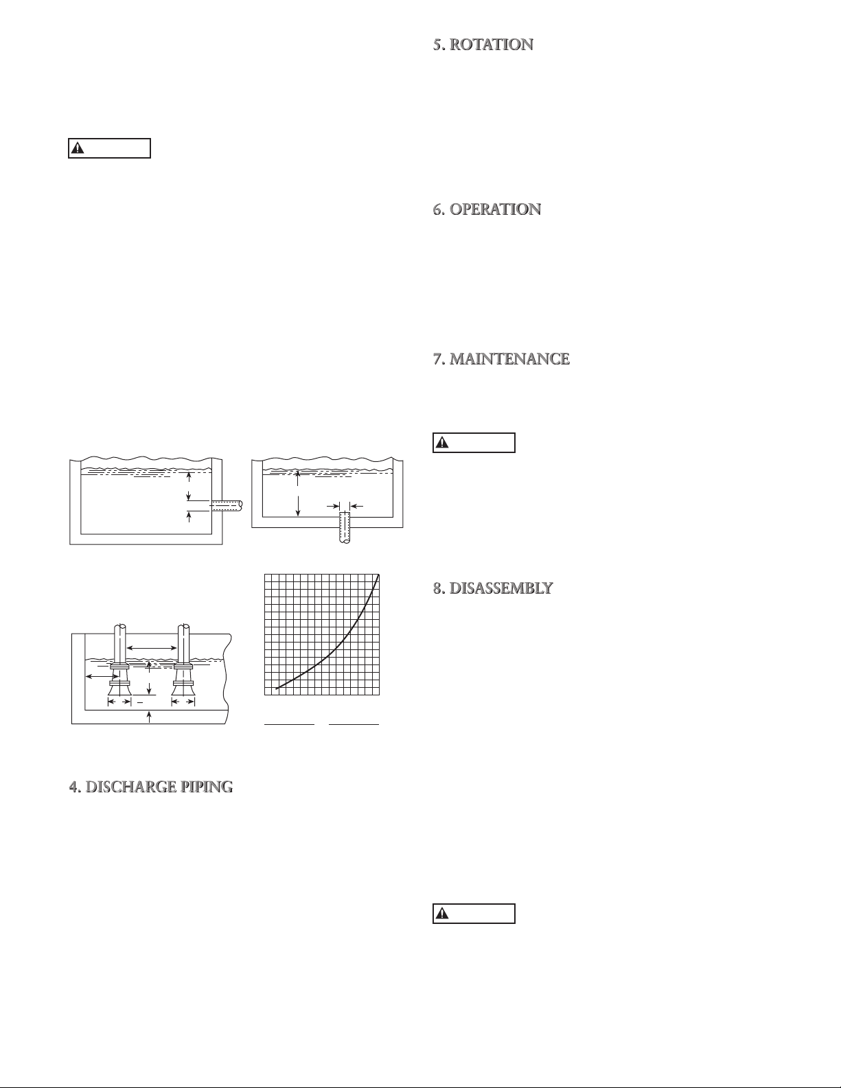
3.6 Size of inlet from liquid source, and minimum sub-
mergence over inlet, must be sufficient to prevent air
entering pump through vortexing. See Figures 1-4.
3.7 Use 3-4 wraps of Teflon™ tape to seal threaded
connections.
H min.
D
Figure 1 Figure 2
3.0D
min.
1.5D
min.
H min.
D min.
D D
2
H min.
H
16
15
14
13
12
11
10
9
8
7
6
5
4
3
2
H = Min. Submergence in feet
1
1234567891011 12131415 16
V = Velocity in feet per second
= GPM x 0.321
Area
GPM x 0.4085
D
V
2
D
Figure 3 Figure 4
4. DISCHARGE PIPING
4.1 Allowance should be made for disconnecting dis-
charge piping near casing to allow for pump disassembly.
4.2 Arrangement must include a check valve located
between a gate valve and the pump. The gate valve
is for regulation of capacity, or for inspection of the
pump or check valve.
4.3 If an increaser is required, place between check valve
and pump.
4.4 Use 3-4 wraps of Teflon tape to seal threaded
connections.
4
5. ROTATION
5.1 Correct rotation is right-hand (clockwise when
viewed from the motor end). Switch power on and
off quickly. Observe shaft rotation. To change rotation:
5.1.1 Single-phase motor: Non-reversible
5.1.2 Three-phase motor: Interchange any two
power supply leads.
6. OPERATION
6.1 Before starting, pump must be primed (free of air
and suction pipe full of liquid) and discharge valve
partially open.
6.2 Make complete check after unit is run under operat-
ing conditions and temperature has stabilized. Check
for expansion of piping.
7. MAINTENANCE
7.1 Ball bearings are located in and are part of the mo-
tor. They are permanently lubricated. No greasing
required.
PUMPED LIQUID PROVIDES LUBRICA-
TION. IF PUMP IS RUN DRY, ROTATING PARTS WILL SEIZE AND MECHANICAL SEAL
WILL BE DAMAGED. DO NOT OPERATE AT OR
NEAR ZERO FLOW. ENERGY IMPARTED TO THE
LIQUID IS CONVERTED INTO HEAT. LIQUID MAY
FLASH TO VAPOR. ROTATING PARTS REQUIRE
LIQUID TO PREVENT SCORING OR SEIZING.
8. DISASSEMBLY
8.1 Complete disassembly of the unit will be described.
Proceed only as for as required to perform the maintenance work required.
8.1.1 Turn off power.
8.1.2 Drain system and flush if necessary.
8.1.3 Disconnect discharge pipe from pump.
8.1.4 Remove motor hold-down bolts.
8.2 Disassembly of Liquid End
8.2.1 Remove casing screws and nuts.
8.2.2 Remove back pull-out assembly from casing.
8.2.3 Remove the first stage diffuser cover and casing
o-ring.
8.2.4 Remove motor fan cover to expose wrench flats
or slot on shaft end.
8.2.5 Hold shaft at flats to resist rotation, and
remove impeller nut and washer.
DO NOT INSERT SCREWDRIVER
BETWEEN THE FAN BLADES TO PREVENT ROTATION.
NOTE: Notice the location of anti-rotation tabs and
holes on items 10, 11, 12 and 13 these must be
aligned and engaged for reassembly.
8.2.6 Remove the first stage impeller, impeller spacer,
intermediate diffuser and last stage diffuser
cover.
Page 5

8.2.7 Remove the last stage impeller and last stage
diffuser.
NOTE: Further disassembly will require removal of the
mechanical seal. It is recommended that a new
mechanical seal be installed at reassembly.
8.2.8 Lubricate the shaft with a 50/50 solution of
glycerin and water. Remove the rotary portion
of the mechanical seal.
8.2.9 Remove the pump body and motor adapter as-
sembly from the motor.
8.2.10 Remove the stationary portion of the mechan-
ical seal from the pump body.
8.2.11 Remove the motor adapter from the pump
body.
8.2.12 To remove the pump shaft from the motor.
Heat must be applied to the pump shaft at the
largest diameter. This is required to break the
bond of the Loctite® #271 between the pump
and motor shafts.
9. REASSEMBLY
9.1 All parts should be cleaned before reassembly.
9.2 Refer to parts list to identify required replacement
items. Specify pump index or catalog number when
ordering parts.
9.3 Reassembly is the reverse of disassembly.
Observe the following when reassembling the pump:
9.4 Check the shaft runout. Maximum permissible is
.010” TIR at the end of the shaft.
9.5 Apply Loctite ‘PrimerN’ and Loctite® #271 to motor
shaft, thread pump shaft in place and torque to 30 lb.
of torque.
9.6 Lubricate pump shaft and pump body stationary seat
holder with a 50/50 glycerin and water solution prior
to installation of mechanical seal components.
9.7 Inspect casing o-ring and impeller o-rings for damage
or wear and replace if necessary.
9.8 O-rings may be lubricated with glycerin and water
solution or petroleum jelly to ease assembly.
9.9 Tighten casing screws to 10 lb.ft. of torque using a
star pattern to prevent o-ring binding.
10. TROUBLESHOOTING CHART
MOTOR NOT RUNNING
(See causes 1 through 6)
LITTLE OR NO LIQUID DELIVERED
(See causes 7 through 17)
POWER CONSUMPTION TOO HIGH
(See causes 4, 17, 18, 19, 22)
EXCESSIVE NOISE AND VIBRATION
(See causes 4, 6, 9, 13, 15, 16, 18, 20, 21, 22)
PROBABLE CAUSE
1. Tripped thermal protector
2. Open circuit breaker
3. Blown fuse
4. Rotating parts binding
5. Motor wired improperly
6. Defective motor
7. Not primed
8. Discharge plugged or valve closed
9. Incorrect rotation
10. Foot valve too small, suction not submerged,
inlet screen plugged
11. Low voltage
12. Phase loss (3-phase only)
13. Air or gasses in liquid
14. System head too high
15. NPSHA too low:
Suction lift too high or suction losses excessive
Check with vacuum gauge
16. Impeller worn or plugged
17. Incorrect impeller diameter
18. Head too low, causing excessive flow rate
19. Viscosity or specific too high
20. Worn bearings
21. Pump or piping loose
22. Pump and motor misaligned
5
Page 6

PARTS LIST
Item No. Description Materials
1 Screw, casing 304SS
2 Pump casing, suction 304SS
Viton
3 O-ring, casing Optional EPR
Optional BUNA
4 Diffuser cover, first stage 304SS
Viton
5 O-ring, impeller Optional EPR
Optional BUNA
6 Impeller nut 304SS
7 Impeller lock washer 400SS
8 Impeller 304SS
9 Impeller spacer 304SS
10 Diffuser, intermediate 304SS
11 Diffuser cover, last stage 304SS
12 Diffuser, last stage 304SS
MECHANICAL SEAL APPLICATION CHART
Rotary Stationary Elastomer Metal Parts Part No.
Silicon carbide Viton
Silicon carbide 10K88
Carbon Silicon carbide EPR 10K89
Ceramic 10K92
Carbon
10K87
316SS
Item No. Description Materials
13 Mechanical seal Varies
14 Fill and drain plug 304SS
15 O-ring, fill and drain plug Viton
16 Pump body with plug 304SS
17 Motor adapter Cast iron
18 Locknut, motor adapter to pump Steel
19 Shaft, pump 304SS
20 Key, impeller 304SS
21 Foot, pump Steel
22 Spacer Rubber
23 Screw, motor adapter to pump Steel
Motor, 3 phase ODP
Motor, 1 phase ODP
24
Motor, 3 phase TEFC
Motor, 1 phase TEFC
25 Nut, casing screw 304SS
23
20
19
14
303SS
24
13
15
10
8
4
2
1
6
9
7
5
3
5
11
12
8
25
16
15
14
18
17
22
21
6
Page 7

GOULDS WATER TECHNOLOGY LIMITED WARRANTY
This warranty applies to all water systems pumps manufactured by Goulds Water Technology.
Any part or parts found to be defective within the warranty period shall be replaced at no charge to the dealer during the warranty period. The warranty period shall exist for a
period of twelve (12) months from date of installation or eighteen (18) months from date of manufacture, whichever period is shorter.
A dealer who believes that a warranty claim exists must contact the authorized Goulds Water Technology distributor from whom the pump was purchased and furnish complete
details regarding the claim. The distributor is authorized to adjust any warranty claims utilizing the Goulds Water Technology Customer Service Department.
The warranty excludes:
(a) Labor, transportation and related costs incurred by the dealer;
(b) Reinstallation costs of repaired equipment;
(c) Reinstallation costs of replacement equipment;
(d) Consequential damages of any kind; and,
(e) Reimbursement for loss caused by interruption of service.
For purposes of this warranty, the following terms have these definitions:
(1) “Distributor” means any individual, partnership, corporation, association, or other legal relationship that stands between Goulds Water Technology and the dealer in
purchases, consignments or contracts for sale of the subject pumps.
(2) “Dealer” means any individual, partnership, corporation, association, or other legal relationship which engages in the business of selling or leasing pumps to customers.
(3) “Customer” means any entity who buys or leases the subject pumps from a dealer. The “customer” may mean an individual, partnership, corporation, limited liability
company, association or other legal entity which may engage in any type of business.
THIS WARRANTY EXTENDS TO THE DEALER ONLY.
Xylem, Inc.
2881 East Bayard Street Ext., Suite A
Seneca Falls, NY 13148
Phone: (800) 453-6777
Fax: (888) 322-5877
www.xyleminc.com/brands/gouldswatertechnology
Goulds is a registered trademark of Goulds Pumps, Inc. and is used under license.
© 2012 Xylem Inc. IM024 Revision Number 6 July 2012
7
Page 8

MANUAL DE INSTRUCCIÓN
IM024
Modelo LC
INSTRUCCIONES DE INSTALACIÓN, FUNCIONAMIENTO Y MANTENIMIENTO
8
Page 9

TEMA PÁGINA
Instrucciones de Seguridad ..........................................................................................................................................10
Notas Importantes .......................................................................................................................................................10
Instalación ...................................................................................................................................................................10
Tubería de Succión ......................................................................................................................................................11
Tubería de Descarga ....................................................................................................................................................11
Rotación ......................................................................................................................................................................11
Operación ...................................................................................................................................................................11
Mantenimiento ............................................................................................................................................................11
Desarmado ..................................................................................................................................................................12
Rearmado ....................................................................................................................................................................12
Cuadro de Identificación de Problemas ........................................................................................................................12
Lista de Partes .............................................................................................................................................................13
Tabla de Aplicación del Sello Mecánico .......................................................................................................................13
Garantía Limitada .......................................................................................................................................................13
Declaración de Conformidad .......................................................................................................................................21
Número de modelo de la bomba:
Número de serie de la bomba:
Representante:
Número telefónico del representante:
Fecha de compra:
Fecha de Instalación:
Lecturas actuales de la puesta en servicio:
1 Ø 3 Ø L1-2 L2-3 L3-1
Amps: Amps:
Voltios: Voltios:
9
Page 10

INSTRUCCIONES DE SEGURIDAD
PARA EVITAR LESIONES PERSONALES GRAVES
O FATALES, Y DAÑOS SIGNIFICATIVOS A LA
PROPIEDAD, LEA Y SIGA TODAS LAS INSTRUCCIONES DE SEGURIDAD QUE SE ENCUENTRAN
EN ESTE MANUAL O EN LA BOMBA.
ESTE MANUAL TIENE LA FUNCIÓN DE ASISTIRLO
EN LA INSTALACIÓN Y OPERACIÓN DE ESTA UNIDAD Y DEBE CONSERVARSE CON LA BOMBA.
Éste es un SÍMBOLO DE ALERTA DE
SEGURIDAD. Cuando vea este símbolo
sobre la bomba o en el manual, localice
una de las siguientes palabras de señalización y esté alerta ante posibles lesiones personales o daños a la propiedad.
PELIGRO
Advierte sobre los peligros que PROVOCARÁN lesiones graves, muerte o daños
significativos a la propiedad.
ADVERTENCIA
Advierte sobre los peligros que
PUEDEN PROVOCAR lesiones graves,
muerte o daños significativos a la propiedad.
PRECAUCIÓN
Advierte sobre los peligros que PROVOCARÁN o PUEDEN PROVOCAR
lesiones o daños a la propiedad.
AVISO: INDICA QUE EXISTEN INSTRUCCIONES
ESPECIALES MUY IMPORTANTES QUE
DEBEN RESPETARSE.
EXAMINE COMPLETAMENTE TODAS LAS INSTRUCCIONES Y ADVERTENCIAS ANTES DE REALIZAR CUALQUIER TRABAJO EN ESTA BOMBA.
CONSERVE TODAS LAS CALCOMANÍAS.
ADVERTENCIA
ESTA UNIDAD NO SE ENCUENTRA
DISEÑADA PARA SER USADA CON
LÍQUIDOS O GASES INFLAMABLES.
ESTOS FLUIDOS PUEDEN ESTAR
PRESENTES EN ÁREAS CONTAMINADAS.
Los fluidos peligrosos
pueden causar
incendios, quemaduras
o la muerte.
DESCRIPCIÓN Y ESPECIFICACIONES
extremo de succión y de acoplamiento cerrado para el
servicio de transferencia general de líquidos, aplicaciones
de unidades reforzadoras, etc. El extremo de líquido es
totalmente de acero inoxidable AISI tipo 304 estampado
y soldado. Los impulsores son del tipo totalmente encerrado y no pueden regularse a diámetros intermedios. Las
carcasas están equipadas con difusores para mejorar la
eficiencia y para aplicar una carga insignificante del eje
radial.
Todas las unidades tienen motores NEMA 48Y o 56Y con
montaje de brida cuadrada y extensión de eje roscado.
1. IMPORTANTE
1.1 Inspeccione la unidad para determinar si está dañada.
Notifique cualquier daño al transportista/agente de
inmediato.
1.2 El suministro eléctrico debe ser un circuito derivado
separado con fusibles o cortacircuitos, tamaños de
alambre, etc. en cumplimiento con los códigos eléc-
tricos nacionales y locales. Instale un desconectador
de todos los circuitos, cerca de la bomba.
PRECAUCIÓN
SIEMPRE DESCONECTE LA CORRIENTE ELÉCTRICA CUANDO MANEJE
LA BOMBA O LOS CONTROLES.
1.3 Los motores deben cablearse para la tensión apro-
piada. El diagrama de cableado del motor está en la
placa del fabricante del motor. El tamaño del alambre
debe limitar la caída máxima de tensión al 10% de
la tensión de la placa del fabricante en los terminales
del motor; de lo contrario se reducirá la vida útil del
motor y disminuirá el rendimiento de la bomba.
1.4 Siempre utilice interruptores, contactadores y ar-
rancadores de potencia nominal.
1.5 Protección del motor:
1.5.1 Unidades monofásicas: A veces la protección
térmica para unidades monofásicas está incorporada (consulte la placa del fabricante). Si no
se proporciona protección incorporada, utilice
un contactador con una sobrecarga apropiada.
Se permite instalar fusibles.
1.5.2 Unidades trifásicas: Proporcione protección
de tres circuitos derivados con arrancador
magnético y sobrecargas térmicas del tamaño
adecuado.
1.6 Límites máximos de operación:
Temperatura del líquido: 220°F (110°C)
Presión de trabajo: 125 lbs./pulg. cuadrada
Arranques por hora: 20, distribuidos
uniformemente.
1.7 La inspección y el mantenimiento regulares aumen-
tarán la vida de servicio. Base la programación en el
tiempo de operación. Consulte la Sección 8.
2. INSTALACIÓN
2.1 Sitúe la bomba lo más cerca posible de la fuente de
líquido (por debajo del nivel de líquido para la operación automática).
2.2 Proteja la bomba contra la congelación o inundación.
2.3 Deje un espacio adecuado para el mantenimiento y la
ventilación.
2.4 Todas las tuberías deben apoyarse independiente-
mente de la bomba y deben “alinearse” naturalmente.
PRECAUCIÓN
EXIONES DE SUCCIÓN Y DE DESCARGA DE LA
BOMBA.
2.5 Evite el uso de accesorios innecesarios. Seleccione los
tamaños para mantener las pérdidas por fricción a un
mínimo.
2.6 Las unidades pueden instalarse horizontales, inclina-
das o verticales.
PRECAUCIÓN
FUGA O CONDENSACIÓN AFECTARÁ EL MOTOR.
NUNCA INSTALE LA TUBERÍA EN
POSICIÓN FORZANDO LAS CON-
NO INSTALAR CON EL MOTOR
DEBAJO DE LA BOMBA. CUALQUIER
10
Page 11

2.7 El cimiento debe ser plano y substancial para elimi-
nar el esfuerzo cuando se aprieten los pernos. Utilice
monturas de caucho para reducir al mínimo el ruido
y la vibración.
2.8 Apriete los pernos de sujeción del motor antes de
conectar las tuberías a la bomba.
3.6 El tamaño de la entrada de la fuente de líquido y la
sumersión mínima sobre la entrada deben ser suficientes para evitar la entrada de aire a través de un
vórtice. Consulte las figuras 1 a 4.
3.7 Aplique tres o cuatro vueltas de cinta de Teflon para
sellar las conexiones roscadas.
3. TUBERÍAS DE SUCCIÓN
3.1 Se desea una elevación de succión estática baja y una
tubería de succión corta y directa. Consulte la curva
de rendimiento de la bomba con respecto a la carga
de succión positiva neta requerida.
3.2 La tubería de succión debe ser al menos del mismo
tamaño que la conexión de succión de la bomba. Un
tamaño más pequeño degradará el rendimiento.
3.3 Si se requiere un tubo más grande, debe instalarse un
reductor de tubo excéntrico (con el lado recto hacia
arriba) en la bomba.
3.4 Instalación con la bomba debajo de la fuente de
suministro:
3.4.1 Instale una válvula de aislamiento de flujo
completo en la tubería para las operaciones de
inspección y mantenimiento.
PRECAUCIÓN
LAR LA BOMBA.
3.5 Instalación con la bomba sobre la fuente de suminis-
tro:
3.5.1 Evite las bolsas de aire. Ninguna parte de la
3.5.2 Todas las juntas deben ser herméticas.
3.5.3 Sólo debe usarse una válvula de aspiración si
3.5.4 El área abierta del colador de succión debe ser
Figura 1 Figura 2
1.5D
mín.
D D
Figura 3 Figura 4
NO UTILICE LA VÁLVULA DE AISLAMIENTO DE SUCCIÓN PARA REGU-
tubería debe estar más alta que la conexión de
succión de la bomba. Incline la tubería hacia
arriba de la fuente de líquido.
es necesario para el cebado o para retener el
cebado en servicio intermitente.
al menos el triple del área del tubo.
3.0D
mín.
H mín.
D mín.
2
H mín.
D
H mín.
H
16
15
14
13
12
11
10
9
8
7
6
5
4
3
2
H = Sumersión mín. en pies
1
1234567891011 12131415 16
V = Velocidad en pies por segundo
= GPM x 0.321
Área
GPM x 0.4085
D
V
2
D
4. TUBERÍAS DE DESCARGA
4.1 Debe incluirse un dispositivo para desconectar la
tubería de descarga cerca de la carcasa para permitir
desmontar la bomba.
4.2 El dispositivo debe incluir una válvula de retención
situada entre una válvula de compuerta y la bomba.
La válvula de compuerta es para regular la capacidad
o para inspeccionar la bomba o la válvula de retención.
4.3 Si se requiere un aumentador, colóquelo entre la
válvula de retención y la bomba.
4.4 Aplique tres o cuatro vueltas de cinta de Teflon para
sellar las conexiones roscadas.
5. ROTACIÓN
5.1 La rotación correcta es hacia la derecha (en el sen-
tido de las agujas del reloj cuando se mira desde el
extremo del motor). Encienda y apague el suministro
eléctrico rápidamente. Observe la rotación del eje.
Para cambiar la rotación:
5.1.1 Motor monofásico: no reversible
5.1.2 Motor trifásico: Intercambie dos conductores
de suministro eléctrico cualesquiera.
6. OPERACIÓN
6.1 Antes de arrancar, la bomba debe cebarse (sin aire y
la tubería de succión debe estar llena de líquido) y la
válvula de descarga debe estar parcialmente abierta.
6.2 Efectúe una revisión completa después de haber
hecho funcionar la unidad en las condiciones de
operación y después que se haya estabilizado la temperatura. Revise para determinar si se ha expandido
la tubería.
7. MANTENIMIENTO
7.1 Los rodamientos están situados en el motor y forman
parte del mismo. Están permanentemente lubricados.
No se requiere engrasar.
PRECAUCIÓN
SE HACE FUNCIONAR SECA, LAS PARTES GIRATORIAS SE AFERRARÁN Y SE DAÑARÁ EL SELLO
MECÁNICO. NO HAGA FUNCIONAR LA UNIDAD
CON UN FLUJO DE CERO O CERCA DE CERO. LA
ENERGÍA APLICADA AL LÍQUIDO SE CONVIERTE
EN CALOR. EL LÍQUIDO PODRÍA VAPORIZARSE
INSTANTÁNEAMENTE. LAS PARTES GIRATORIAS
REQUIEREN LÍQUIDO PARA EVITAR LAS RAYADURAS O AFERRAMIENTO.
EL LÍQUIDO BOMBEADO PROPORCIONA LUBRICACIÓN. SI LA BOMBA
11
Page 12

8. DESARMADO
8.1 Se describirá el desmontaje completo de la unidad.
Desmonte sólo lo necesario para realizar el trabajo de
mantenimiento requerido.
8.1.1 Apague la unidad.
8.1.2 Drene el sistema y enjuáguelo si es necesario.
8.1.3 Desconecte el tubo de descarga de la bomba.
8.1.4 Quite los pernos de sujeción del motor.
8.2 Desmontaje del extremo del líquido
8.2.1 Quite los tornillos y pernos de la carcasa.
8.2.2 Retire el conjunto de desmontaje trasero de la
carcasa.
8.2.3 Retire la tapa del difusor de la primera etapa y
el anillo en O de la carcasa.
8.2.4 Retire la tapa del ventilador del motor para de-
jar al descubierto las secciones planas o ranura
para la llave en el extremo del eje.
8.2.5 Sujete el eje en las secciones planas para resistir
la rotación y retire la tuerca y arandela del
impulsor.
PRECAUCIÓN
DOR PARA EVITAR LA ROTACIÓN.
NOTA: Note la ubicación de las lengüetas antirrotación
y los orificios en los artículos 10, 11, 12 y 13; estos
deben alinearse y engancharse para el rearmado.
8.2.6 Retire el impulsor de la primera etapa, espacia-
8.2.7 Retire el impulsor de la última etapa y el difu-
NOTA: El desmontaje adicional requerirá retirar el sello
mecánico. Se recomienda instalar un nuevo sello
mecánico al reensamblar.
8.2.8 Lubrique el eje con una solución 50/50 de glic-
8.2.9 Retire el cuerpo de la bomba y el conjunto del
8.2.10 Retire la parte estacionaria del sello mecánico
8.2.11 Retire el adaptador para el motor del cuerpo
8.2.12 Para retirar el eje de la bomba del motor debe
NO INSERTE UN DESTORNILLADOR
ENTRE LAS PALETAS DEL VENTILA-
dor del impulsor, difusor intermedio y la tapa
del difusor de la última etapa.
sor de la última etapa.
erina y agua. Retire la parte mecánica del sello
mecánico.
adaptador para el motor del motor.
del cuerpo de la bomba.
de la bomba.
aplicarse calor al eje de la bomba en el diámetro más grande. Esto es necesario para desprender la adherencia del compuesto Loctite
#271 entre los ejes de la bomba y del motor.
9. REARMADO
9.1 Deben limpiarse todas las partes antes del reensamb-
laje.
9.2 Consulte la lista de partes para identificar los artícu-
los de reemplazo requeridos. Especifique el número
de índice o de catálogo cuando ordene partes.
9.3 Reensamble en el orden inverso del desmontaje.
12
Observe lo siguiente cuando reensamble la bomba:
9.4 Verifique la deflexión del eje. El valor máximo per-
mitido es 0.010 pulg. TIR (lectura total del indicador) en el extremo del eje.
9.5 Aplique Loctite ‘Primer N’ y Loctite #271 al eje del
motor, atornille el eje de la bomba en posición y
torsione a 30 lbs.
9.6 Lubrique el eje de la bomba y el portaasiento esta-
cionario del cuerpo de la bomba con una solución
50/50 de glicerina y agua antes de la instalación de
los componentes del sello mecánico.
9.7 Inspeccione el anillo en O de la carcasa y los anillos
en O del impulsor para determinar si están dañados o
gastados y reemplácelos si es necesario.
9.8 Los anillos en O pueden lubricarse con una solución
de glicerina y agua o gelatina de petróleo para facilitar el montaje.
9.9 Apriete los tornillos de la carcasa a una torsión de 10
lb.-pies en una configuración de estrella para evitar el
atascamiento de los anillos en O.
10. CUADRO DE IDENTIFICACIÓN
DE PROBLEMAS
EL MOTOR NO ESTÁ FUNCIONANDO
(Ver las causas 1 a 6)
SE ENTREGA POCO O NADA DE LÍQUIDO
(Ver las causas 7 a 17)
EL CONSUMO DE ELECTRICIDAD ES DEMASIADO ALTO
(Ver las causas 4, 17, 18, 19, 22)
RUIDO Y VIBRACIÓN EXCESIVOS
(Ver las causas 4, 6, 9, 13, 15, 16, 18, 20, 21, 22)
CAUSA PROBABLE
1. Protector térmico disparado
2. Cortacircuitos abierto
3. Fusible quemado
4. Roce de las partes giratorias
5. Cableado incorrecto del motor
6. Motor defectuoso
7. Falta de cebado
8. Descarga bloqueada o válvula cerrada
9. Rotación incorrecta
10. Válvula de aspiración demasiado pequeña, la succión
no está sumergida, el filtro de entrada está tapado
11. Baja tensión
12. Pérdida de fase (unidades trifásicas únicamente)
13. Aire o gases en el líquido
14. Carga del sistema demasiado alta
15. Carga de succión positiva neta disponible (NPSHA)
demasiado baja:
Elevación de succión demasiado alta o pérdidas de
succión excesivas
Revise con un indicador de vacío
16. Impulsor gastado o taponado
17. Diámetro incorrecto del impulsor
18. Carga demasiado baja, produciendo una velocidad de
flujo excesiva
19. Viscosidad o peso específico del fluido demasiado alto
20. Cojinetes gastados
21. Bomba o tubería suelta
22. Bomba y motor desalineados
Page 13

LISTA DE PARTES
Artículo N°. Descripción Materiales
1 Tornillo, de la carcasa Acero inox. 304
2 Carcasa de la bomba, extremo de succión Acero inox. 304
Viton
3 Anillo en O, de la carcasa EPR opcional
BUNA opcional
4 Tapa del difusor, primera etapa Acero inox. 304
Viton
5 Anillo en O, del impulsor EPR opcional
BUNA opcional
6 Tuerca del impulsor Acero inox. 304
7 Arandela de seguridad del impulsor Acero inox. 400
8 Impulsor Acero inox. 304
9 Espaciador del impulsor Acero inox. 304
10 Difusor, intermedio Acero inox. 304
11 Difusor, tapa, última etapa Acero inox. 304
12 Difusor, última etapa Acero inox. 304
TABLA DE APLICACIÓN DEL SELLO MECÁNICO
Giratorio Estacionario Elastómero Partes de metal Nº de parte
Carburo de silicio Viton
Carburo de silicio
Carbón Carburo de silicio EPR 10K89
Cerámica
Carbón
10K92
Acero
inoxidable
10K88
316
10K87
Artículo N°. Descripción Materiales
13 Sello mecánico Varía
14 Tapón de llenado y drenaje Acero inox. 304
15 Anillo en O, tapón de llenado y drenaje Viton
16 Cuerpo de la bomba con tapón Acero inox. 304
17 Adaptador para el motor Hierro fundido
18 Contratuerca, adaptador para el motor a la bomba Acero
19 Eje, de la bomba Acero inox. 304
20 Chaveta, del impulsor Acero inox. 304
21 Soporte, de la bomba Acero
22 Espaciador Caucho
23 Tornillo, adaptador para el motor a la bomba Acero
Motor, trifásico, ODP
Motor, monofásico, abierto resguardado, ODP Acero inox.
24
Motor, trifásico, TEFC 303
Motor, monofásico, TEFC
25 Tuerca, tornillo de la carcasa Acero inox. 304
ODP = abierto resguardado
TEFC = totalmente encerrado y enfriado con ventilador
23
20
19
14
24
13
15
10
8
4
2
1
6
9
7
5
3
5
11
12
8
25
16
15
14
18
17
22
21
13
Page 14

GARANTÍA LIMITADA DE GOULDS WATER TECHNOLOGY
Esta garantía es aplicable a todas las bombas para sistemas de agua fabricadas por Goulds Water Technology.
Toda parte o partes que resulten defectuosas dentro del período de garantía serán reemplazadas sin cargo para el comerciante durante dicho período de garantía. Tal período de
garantía se extiende por doce (12) meses a partir de la fecha de instalación, o dieciocho (18) meses a partir de la fecha de fabricación, cualquiera se cumpla primero.
Todo comerciante que considere que existe lugar a un reclamo de garantía deberá ponerse en contacto con el distribuidor autorizado de Goulds Water Technology del
cual adquiriera la bomba, y ofrecer información detallada con respecto al reclamo. El distribuidor está autorizado a liquidar todos los reclamos por garantía a través del
Departamento de Servicios a Clientes de Goulds Water Technology.
La presente garantía excluye:
(a) La mano de obra, el transporte y los costos relacionados en los que incurra el comerciante;
(b) los costos de reinstalación del equipo reparado;
(c) los costos de reinstalación del equipo reemplazado;
(d) daños emergentes de cualquier naturaleza; y
(e) el reembolso de cualquier pérdida causada por la interrupción del servicio.
A los fines de esta garantía, los términos “Distribuidor”, “Comerciante” y “Cliente” se definen como sigue:
(1) “Distribuidor” es aquel individuo, sociedad, corporación, asociación u otra entidad jurídica que opera entre Goulds Water Technology y el comerciante para la compra,
consignación o contratos de venta de las bombas en cuestión.
(2) “Comerciante” es todo individuo, sociedad, corporación, asociación u otra entidad jurídica que realiza negocios de venta o alquiler-venta (leasing) de bombas a clientes.
(3) “Cliente” es toda entidad que compra o que adquiere bajo la modalidad de leasing las bombas en cuestión de un comerciante. El término “cliente” puede significar un
individuo, una sociedad, una corporación, una sociedad de responsabilidad limitada, una asociación o cualquier otra entidad jurídica con actividades en cualquier tipo de
negocios.
LA PRESENTE GARANTÍA SE EXTIENDE AL COMERCIANTE ÚNICAMENTE
Xylem, Inc.
2881 East Bayard Street Ext., Suite A
Seneca Falls, NY 13148
Teléfono: (800) 453-6777
Fax: (888) 322-5877
www.xyleminc.com/brands/gouldswatertechnology
Goulds es una marca registrada de Goulds Pumps, Inc. y se utiliza bajo licencia.
© 2012 Xylem Inc. IM024 Revisión Número 6 Julio 2012
Page 15

MANUEL D'UTILISATION
IM024
Modèle LC
DIRECTIVES D’INSTALLATION, D’UTILISATION ET D’ENTRETIEN
Page 16

SUJET PAGE
Consignes de Sécurité .................................................................................................................................................. 17
Informations Importantes ............................................................................................................................................ 17
Installation .................................................................................................................................................................. 17
Tuyauterie D'aspiration ................................................................................................................................................ 18
Tuyauterie de Refoulement .......................................................................................................................................... 18
Rotation ...................................................................................................................................................................... 18
Utilisation .................................................................................................................................................................... 18
Entretien ..................................................................................................................................................................... 18
Démontage .................................................................................................................................................................. 19
Remontage .................................................................................................................................................................. 19
Diagnostic des Anomalies ............................................................................................................................................ 19
Liste de Pièces ............................................................................................................................................................. 20
Table des Garnitures (Joints) Mécaniques .................................................................................................................... 20
Garantie Limitée..........................................................................................................................................................20
Déclaration de Conformité .......................................................................................................................................... 21
Informations pour le propriétaire
Numéro de modèle de la pompe :
Numéro de série de la pompe :
Détaillant :
Nº de téléphone du détaillant :
Date d’achat :
Date d’installation :
Courant mesuré au démarrage :
1 Ø 3 Ø L1-2 L2-3 L3-1
A : A :
V : V :
16
Page 17

CONSIGNES DE SÉCURITÉ
DANGER
AVERTISSEMENT
AVERTISSEMENT
Les fluides dangereux
peuvent causer un
incendie, des brûlures
ou la mort.
AFIN DE PRÉVENIR LES BLESSURES GRAVES OU
MORTELLES ET LES DOMMAGES MATÉRIELS
IMPORTANTS, LIRE ET SUIVRE TOUTES LES
CONSIGNES DE SÉCURITÉ FIGURANT DANS LE
MANUEL ET SUR LA POMPE.
LE PRÉSENT MANUEL A POUR BUT DE FACILITER
L’INSTALLATION ET L’UTILISATION DE LA POMPE ET DOIT RESTER PRÈS DE CELLE-CI.
Le symbole ci-contre est un SYMBOLE
DE SÉCURITÉ employé pour signaler
les mots-indicateurs dont on trouvera la
description ci-dessous. Sa présence sert à
attirer l’attention afin d’éviter les blessures
et les dommages matériels.
Prévient des risques qui VONT causer
des blessures graves, la mort ou des
dommages matériels importants.
Prévient des risques qui PEUVENT
causer des blessures graves, la mort ou
des dommages matériels importants.
ATTENTION
AVIS : SERT À ÉNONCER LES DIRECTIVES
SPÉCIALES DE GRANDE IMPORTANCE
QUE L’ON DOIT SUIVRE.
LIRE SOIGNEUSEMENT CHAQUE DIRECTIVE ET
AVERTISSEMENT AVANT D’EFFECTUER TOUT
TRAVAIL SUR LA POMPE.
N’ENLEVER AUCUN AUTOCOLLANT DE SÉCURITÉ.
Prévient des risques qui PEUVENT causer
des blessures ou des dommages matériels.
APPAREIL NON CONÇU POUR LES
LIQUIDES DANGEREUX NI POUR
LES GAZ INFLAMMABLES. CES
FLUIDES POURRAIENT ÊTRE PRÉSENTS DANS LES INSTALLATIONS
DE CONFINEMENT (PUITS COLLECTEURS).
l’électricité. Poser un sectionneur tout conducteur
près de la pompe.
ATTENTION
ON DOIT TOUJOURS COUPER LE
COURANT LORSQUE L’ON EFFECTUE
QUELQUE TRAVAIL QUE CE SOIT SUR LA POMPE
OU LES COMMANDES.
1.3. Le câblage d’alimentation du moteur doit convenir à
la tension de fonctionnement. Le schéma de câblage
se trouve sur la plaque signalétique du moteur. Les
fils doivent avoir un calibre limitant la chute de tension maximale, aux bornes du moteur, à 10 % de la
valeur de tension indiquée sur la plaque signalétique,
sinon la durée de vie du moteur et les performances
de la pompe diminueront.
1.4. Il faut toujours employer des contacteurs et des
démarreurs de puissance nominale en horse-power
(hp).
1.5. Protection du moteur
1.5.1. Moteurs monophasés – Ces moteurs sont
parfois munis d’une protection thermique intégrée (voir la plaque signalétique). Dans le cas
contraire, utiliser un contacteur à protection
appropriée contre les surcharges. Les dispositifs fusibles sont admissibles.
1.5.2. Moteurs triphasés – Employer une protec-
tion trois conducteurs appropriée contre les
surcharges thermiques ainsi qu’un démarreur
magnétique convenant à la charge électrique.
1.6. Limites d’utilisation maximales
Température du liquide : 110 °C (220 °F)
Pression : 125 lb/po
2
Démarrages par heure : 20, répartis uniformément
1.7. Une inspection et un entretien réguliers augment-
eront la durée de vie de l’appareil. Établir un programme d’entretien et d’inspection basé sur le temps
de fonctionnement. Voir la section 8.
DESCRIPTION et CARACTÉRISTIQUES
Le modèle LC est une pompe centrifuge à deux étages
formant un groupe monobloc (montée sur moteur), à
aspiration en bout, servant au transfert de liquides de
nature générale, à l’augmentation de pression, etc. La tête
de pompage est tout en inox AISI de type 304 estampé et
soudé. Les roues sont fermées et ne peuvent être réduites
à un diamètre intermédiaire. Le corps de pompe est muni
de diffuseurs pour améliorer le rendement et rendre la
charge radiale de l’arbre négligeable.
La LC est dotée d’un moteur conforme aux normes
NEMA 48Y et 56Y, muni d’une bride de fixation carrée
et d’un arbre-rallonge fileté.
1. INFORMATIONS IMPORTANTES
1.1. Inspecter l’appareil et signaler immédiatement tout
1.2. L’alimentation électrique doit être assurée par un
dommage au transporteur ou au détaillant.
circuit de dérivation distinct dont les fusibles ou les
disjoncteurs, le calibre des fils, etc. sont conformes
aux prescriptions du code provincial ou national de
2. INSTALLATION
2.1. Placer la pompe aussi près de la source de liquide
que possible (au-dessous du niveau du liquide pour
qu’elle fonctionne automatiquement).
2.2. Protéger l’appareil contre les inondations et le gel.
2.3. Prévoir assez d’espace autour de la pompe pour
l’entretien et l’aération.
2.4. La tuyauterie doit posséder ses propres supports et
« être alignée » sans contraintes sur la pompe.
ATTENTION
PLIQUER DE CONTRAINTES SUR LES RACCORDS
D’ASPIRATION ET DE REFOULEMENT DE LA
POMPE.
2.5. Ne poser aucun accessoire ni raccord de tuyauterie
superflus. Choisir le calibre approprié pour réduire
les pertes de charge au minimum.
2.6. Les pompes peuvent être installées à l’horizontale, à
la verticale ou sur une surface inclinée.
LA TUYAUTERIE DOIT ÊTRE PO-
SÉE DE FAÇON À NE JAMAIS AP-
17
Page 18

ATTENTION
NE PAS PLACER LE MOTEUR PLUS
BAS QUE LA POMPE AFIN DE LE PROTÉGER CONTRE LES FUITES ET L’EAU DE CONDENSATION.
2.7. On doit fixer l’appareil à une dalle plane et solide
pour empêcher que le serrage des boulons ne cause
de contraintes. Monter l’appareil sur caoutchouc
pour réduire le bruit et les vibrations au minimum.
2.8. Serrer les boulons de fixation du moteur avant de
raccorder la tuyauterie à la pompe.
3. TUYAUTERIE D’ASPIRATION
3.1. Une hauteur géométrique d’aspiration réduite et
une tuyauterie directe et courte sont souhaitables.
Consulter la courbe de performances de la pompe
pour obtenir la hauteur nette d’aspiration requise
(NPSHR).
3.2. Le calibre du tuyau d’aspiration doit être au moins
égal à celui du raccord d’aspiration de la pompe
pour éviter les pertes de performances.
3.3. S’il faut un tuyau plus gros, on doit installer un
raccord réducteur excentré (le côté non oblique en
haut) à la pompe.
3.4. Pompe placée plus bas que la source de liquide :
3.4.1. Poser un robinet d’isolement à passage intégral
sur le tuyau d’aspiration pour l’inspection et
l’entretien.
ATTENTION
SECTION DE PASSAGE VERS LA POMPE.
3.5. Pompe placée plus haut que la source de liquide :
3.5.1. Afin de prévenir les poches d’air, aucun élé-
3.5.2. Chaque joint doit être étanche.
3.5.3. On n’emploiera un clapet de pied que s’il est
Figure 1 Figure 2
1,5d
min.
Figure 3 Figure 4
18
NE PAS EMPLOYER LE ROBINET
D’ISOLEMENT POUR RÉDUIRE LA
ment de la tuyauterie d’aspiration ne devrait
être plus haut que le raccord d’aspiration de la
pompe. Donner à la tuyauterie une inclinaison
vers le haut à partir de la source de liquide.
requis pour amorcer la pompe ou la maintenir
amorcée pendant les arrêts.
3,0d
min.
h min.
d min.
d d
2
h min.
d
h min.
d
h
16
15
14
13
12
11
10
9
8
7
6
5
4
3
2
1
h = hauteur d’immersion minimale (pi)
1234567891011 12131415 16
v = vitesse d’écoulement (pi/s)
= gal US/min x 0,321
section de passage
gal US/min x 0,408 5
d
2
3.5.4. La section de passage de la crépine du tuyau
d’aspiration doit être au moins le triple de
celle du tuyau.
3.6. Le diamètre (d) et la hauteur d’immersion minimale
(h min.) de l’entrée du tuyau d’aspiration doivent
être suffisants pour empêcher l’aspiration d’air par
vortex (v. fig. 1 à 4).
3.7. Enrouler les raccords filetés de 3 ou 4 couches de
ruban de téflon pour les étancher.
4. TUYAUTERIE DE REFOULEMENT
4.1. Prévoir assez d’espace près du corps de pompe pour
pouvoir déconnecter le tuyau de refoulement et
démonter la pompe.
4.2. L’installation doit comporter un robinet-vanne, ainsi
qu’un clapet de non-retour placé entre le robinetvanne et la pompe. Le robinet-vanne sert au réglage
du débit et à l’inspection de la pompe et du clapet de
non-retour.
4.3. Si un raccord agrandisseur est nécessaire, le poser
entre le clapet de non-retour et la pompe.
4.4. Enrouler les raccords filetés de 3 ou 4 couches de
ruban de téflon pour les étancher.
5. SENS DE ROTATION
5.1. La rotation appropriée est en sens horaire (vers la
droite, vue de l’extrémité du moteur). Démarrer et
arrêter la pompe immédiatement tout en observant
le sens de rotation de l’arbre. Changer le sens de
rotation comme suit.
5.1.1. Moteur monophasé : irréversible.
5.1.2. Moteur triphasé : intervertir deux conducteurs
d’alimentation du moteur.
6. UTILISATION
6.1. Avant de mettre la pompe en service, on doit
l’amorcer (pour en chasser l’air), remplir de liquide
le tuyau d’aspiration et entrouvrir le robinet de
refoulement.
6.2. Faire fonctionner l’appareil dans des conditions nor-
males jusqu’à ce que sa température se stabilise, puis
vérifier tout le système. Vérifier également la dilatation de la tuyauterie.
7. ENTRETIEN
7.1. Les roulements sont situés à l’intérieur du moteur et
sont lubrifiés à vie. Aucun graissage n’est requis.
ATTENTION
À SEC, LES PIÈCES MOBILES GRIPPERAIENT, ET LA
GARNITURE MÉCANIQUE S’ENDOMMAGERAIT. IL
NE FAUT DONC PAS FAIRE MARCHER LA POMPE
LORSQUE SON DÉBIT EST NUL OU PRESQUE, CAR
LE PEU DE LIQUIDE S’Y TROUVANT ABSORBERAIT
LA CHALEUR PRODUITE PAR FROTTEMENT ET
v
POURRAIT SE CHANGER RAPIDEMENT EN VAPEUR. LES PIÈCES MOBILES DOIVENT ÊTRE LUBRIFIÉES PAR LE LIQUIDE POUR NE PAS S’ABÎMER NI
GRIPPER.
LES LIQUIDES POMPÉS SERVENT DE
LUBRIFIANT. SI LA POMPE TOURNAIT
Page 19

8. DÉMONTAGE
8.1. Le démontage complet de la pompe est décrit ci-
dessous. Ne démonter que ce qui permet de faire
l’entretien requis.
8.1.1. Couper le courant.
8.1.2. Vidanger le système. Le rincer au besoin.
8.1.3. Séparer le tuyau de refoulement d’avec la
pompe.
8.1.4. Enlever les boulons de fixation du moteur.
8.2. Tête de pompage
8.2.1. Enlever les vis et les écrous assujettissant les
demi-corps de pompe.
8.2.2. Écarter l’ensemble d’entraînement de la roue
d’avec le demi-corps de pompe, côté aspiration.
8.2.3. Enlever le couvercle du diffuseur du premier
étage et le joint torique des demi-corps de
pompe.
8.2.4. Ôter le couvercle de ventilateur du moteur
pour accéder aux méplats ou à la fente de
blocage de l’arbre, à l’extrémité de celui-ci.
8.2.5. Bloquer l’arbre, puis enlever l’écrou de
blocage des roues et la rondelle-frein.
9.3. Le remontage se fait dans l’ordre inverse du démon-
tage.
Suivre les directives ci-dessous en remontant la pompe :
9.4. Vérifier si l’arbre comporte un faux-rond : le maxi-
mum admissible est de 0,010 po au bout de l’arbre.
9.5. Enduire le bout de l’arbre de moteur d’apprêt Loc-
tite « Primer N », puis de Loctite no 271, visser
l’arbre de pompe à l’arbre de moteur et le serrer à 30
lbf·pi.
9.6. Avant de poser la garniture mécanique, lubrifier
l’arbre de pompe et le logement de garniture, au
centre du demi-corps de pompe, avec une solution
contenant moitié glycérine et moitié eau.
9.7. Inspecter le joint torique des demi-corps de pompe
et les joints toriques des roues. Les remplacer s’ils
sont endommagés ou usés.
9.8. On peut enduire les joints toriques de pétrolatum
(vaseline) ou d’une solution de glycérine et d’eau
pour en faciliter la pose.
9.9. Poser et serrer les vis des demi-corps de pompe à 10
lbf·pi, en croix, pour éviter toute déformation excessive du joint torique.
ATTENTION
POUR EMPÊCHER L’ARBRE DE TOURNER.
NOTA : Remarquer la position des pattes et des crans
antirotation des articles 10 à 13, car il faut les aligner
et les insérer correctement pour les remonter.
8.2.6. Enlever la roue du premier étage, son en-
8.2.7. Déposer la roue du second étage et son dif-
NOTA : Un démontage plus poussé nécessitera la dépose
de la garniture mécanique, qu’il est recommandé de
remplacer alors par une neuve.
8.2.8. Lubrifier l’arbre avec une solution conten-
8.2.9. Déposer l’ensemble adaptateur de moteur et
8.2.10. Extraire du demi-corps de pompe l’élément
8.2.11. Séparer l’adaptateur de moteur d’avec le
8.2.12. Pour enlever l’arbre de pompe, on doit le
NE PAS INSÉRER DE TOURNEVIS
ENTRE LES PALES DU VENTILATEUR
tretoise, son diffuseur et le couvercle du diffuseur du second étage.
fuseur.
ant moitié glycérine et moitié eau, puis ôter
l’élément mobile de la garniture mécanique.
demi-corps de pompe, côté refoulement.
fixe de la garniture mécanique.
demi-corps de pompe.
chauffer dans sa partie la plus épaisse afin
d’éliminer l’adhérence du Loctite no 271, puis
le dévisser de l’arbre de moteur.
9. REMONTAGE
9.1. Chaque pièce devrait être nettoyée avant le remontage.
9.2. Voir la liste de pièces pour déterminer les pièces de
rechange requises. Préciser le numéro de pièce ou de
catalogue de la pompe lorsque l’on commande des
pièces.
10. DIAGNOSTIC DES ANOMALIES
NON-FONCTIONNEMENT DU MOTEUR
(V. causes probables 1 à 6)
DÉBIT DE LIQUIDE FAIBLE OU NUL
(V. causes probables 7 à 17)
CONSOMMATION D’ÉNERGIE EXCESSIVE
(V. causes probables 4, 17, 18, 19 et 22)
VIBRATION ET BRUIT EXCESSIFS
(V. causes probables 4, 6, 9, 13, 15, 16, 18, 20, 21 et 22)
CAUSE PROBABLE
1. Protecteur thermique déclenché
2. Disjoncteur ouvert
3. Fusible sauté
4. Pièces mobiles grippées
5. Moteur mal connecté
6. Moteur défectueux
7. Pompe non amorcée
8. Tuyau de refoulement obstrué ou robinet fermé
9. Mauvais sens de rotation
10. Clapet de pied trop petit, entrée de tuyau
d’aspiration non immergée, crépine obstruée
11. Basse tension électrique
12. Perte de phase (moteurs triphasés seulement)
13. Présence d’air ou de gaz dans le liquide
14. Hauteur de charge du système trop élevée
15. Hauteur nette d’aspiration disponible (NPSHA) trop
faible : hauteur ou perte d’aspiration excessives – à
vérifier avec un vacuomètre
16. Roue(s) usée(s) ou engorgée(s)
17. Diamètre de roue inapproprié
18. Hauteur de charge trop faible : débit excessif
19. Viscosité ou densité trop élevées
20. Roulement(s) usé(s)
21. Pompe ou tuyauterie mal assujetties
22. Pompe et moteur désalignés
19
Page 20

LISTE DE PIÈCES
No d’art. Description Matériau
1 Vis (demi-corps de pompe) Inox 304
2 Demi-corps de pompe, côté aspiration Inox 304
Viton
3 Joint torique (demi-corps de pompe) Éthyl.-propyl. (option)
Buna (option)
4 Couvercle du diffuseur (1er étage) Inox 304
Viton
5 Joints toriques (roues) Éthyl.-propyl. (option)
Buna (option)
6 Écrou de blocage (roues) Inox 304
7 Rondelle-frein (roues) Inox 400
8 Roues Inox 304
9 Entretoise (roues) Inox 304
10 Diffuseur (1er étage) Inox 304
11 Couvercle du diffuseur (2e étage) Inox 304
12 Diffuseur (2e étage) Inox 304
TABLE DES GARNITURES MÉCANIQUES
Élément mobile Élément fixe Élastomère Métal No de pièce
Carbure de silicium Viton 10K87
Carbure de silicium
Carbone Carbure de silicium Éthyl.-propyl. 10K89
Céramique 10K92
Carbone
Inox 316
10K88
No d’art. Description Matériau
13 Garniture mécanique Voir Table...
14 Bouchons (remplissage et vidange) Inox 304
15 Joints toriques (bouchons) Viton
16 Demi-corps de pompe, côté refoulement Inox 304
17 Adaptateur de moteur Fonte
Écrou autofreiné de blocage
18
(pompe-adaptateur de moteur)
19 Arbre de pompe Inox 304
20 Clavette (roues) Inox 304
21 Plaque-support (moteur) Acier
22 Entretoise Caoutchouc
23 Vis (moteur-adaptateur de moteur) Acier
Moteur, 3 PH, abrité➀
Moteur, 1 PH, abrité
24
Moteur, 3 PH, fermé autoventilé
Moteur, 1 PH, fermé autoventilé
25 Écrous (demi-corps de pompe) Inox 304
➀
abrité = à ouvertures de ventilation protégées
Acier
Inox 303
23
20
19
14
24
13
15
10
8
4
2
1
6
9
7
5
3
5
11
12
8
25
16
15
14
18
17
22
21
20
Page 21

Declaration of Conformity
Declaration of Conformity
We at,
Goulds Water Technology/Xylem Inc.
1 Goulds Drive
Auburn, NY 13021
Declare that the following products: NPE, MCS, MCC, 3656, 3656 SP, GB, e-SV, SVI, NPO, Prime Line
SP, HB, HMS, LC, NPV, LB, LBS comply with Machine Directive 06/42/EC. This equipment is intended
to be incorporated with machinery covered by this directive, but must not be put into service until the
machinery into which it is to be incorporated has been declared in conformity with the actual provisions
of the directive.
Declaración de Conformidad
Declaración de Conformidad
Nosotros en
Goulds Water Technology/Xylem Inc.
1 Goulds Drive
Auburn, NY 13021
Declaramos que los siguientes productos: NPE, MCS, MCC, 3656, 3656 SP, GB, e-SV, SVI, NPO, Prime
Line SP, HB, HMS, LC, NPV, LB, LBS cumplen con las Directivas para Maquinarias 06/42/EC. Este
equipo ha sido diseñado para ser incorporado a la maquinaria cubierta por esta directiva pero no debe
ponerse en funcionamiento hasta que se declare que la maquinaria en la que será incorporado cumple
con las disposiciones reales de la directiva.
Déclaration de Conformité
Déclaration de Conformité
Nous, à
Goulds Water Technology/Xylem Inc.
1 Goulds Drive
Auburn, NY, U.S.A. 13021,
déclarons que les produits NPE, MCS, MCC, 3656, 3656 SP, GB, e-SV, SVI, NPO, Prime Line SP, HB,
HMS, LC, NPV, LB et LBS sont conformes à la directive 06/42/EC (législation relative aux machines). Ils
sont destinés à être intégrés dans la machinerie faisant l’objet de ladite directive, mais ne doivent pas être
mis en service tant que la machinerie en question ne sera pas déclarée conforme aux stipulations de la
directive.
21
Page 22

NOTES/NOTAS
22
Page 23

NOTES/NOTAS
23
Page 24

GARANTIE LIMITÉE DE GOULDS WATER TECHNOLOGY
La présente garantie s’applique à chaque pompe de système d’alimentation en eau fabriquée par Goulds Water Technology.
Toute pièce se révélant défectueuse durant la période de garantie sera remplacée sans frais pour le détaillant durant ladite période, qui dure douze (12) mois à compter de la
date d’installation ou dix-huit (18) mois à partir de la date de fabrication, soit la période qui expirera la première.
Le détaillant qui, aux termes de cette garantie, désire effectuer une demande de règlement doit s’adresser au distributeur Goulds Water Technology agréé chez lequel la pompe
a été achetée et fournir tous les détails à l’appui de sa demande. Le distributeur est autorisé à régler toute demande par le biais du service à la clientèle de Goulds Water
Technology.
La garantie ne couvre pas :
a) les frais de main-d’oeuvre ou de transport ni les frais connexes encourus par le détaillant ;
b) les frais de réinstallation de l’équipement réparé ;
c) les frais de réinstallation de l’équipement de remplacement ;
d) les dommages indirects de quelque nature que ce soit ;
e) ni les pertes découlant de la panne.
Aux fins de la présente garantie, les termes ci-dessous sont définis comme suit :
1) «Distributeur» signifie une personne, une société de personnes, une société de capitaux, une association ou autre entité juridique servant d’intermédiaire entre Goulds
Water Technology et le détaillant pour les achats, les consignations ou les contrats de vente des pompes en question.
2) «Détaillant» veut dire une personne, une société de personnes, une société de capitaux, une association ou autre entité juridique dont les activités commerciales sont la
vente ou la location de pompes à des clients.
3) «Client» signifie une entité qui achète ou loue les pompes en question chez un détaillant. Un «client» peut être une personne, une société de personnes, une société de
capitaux, une société à responsabilité limitée, une association ou autre entité juridique se livrant à quelque activité que ce soit.
CETTE GARANTIE SE RAPPORTE AU DÉTAILLANT SEULEMENT.
24
Xylem, Inc.
2881 East Bayard Street Ext., Suite A
Seneca Falls, NY 13148
Téléphone: (800) 453-6777
Télécopie: (888) 322-5877
www.xyleminc.com/brands/gouldswatertechnology
Goulds est une marque déposée de Goulds Pumps, Inc. et est utilisé sous le permis.
© 2012, Xylem Inc. IM024 Révision numéro 6 Juillet 2012
 Loading...