

Page 1
Installation, Operation, and
Maintenance Manual
887673_1.0
FST
Page 2

Page 3

Table of Contents
1 Introduction and Safety............................................................................................ 3
1.1 Introduction........................................................................................................3
1.2 Safety terminology and symbols..................................................................... 3
1.3 User safety.......................................................................................................... 4
1.3.1 Power lock-out........................................................................................... 5
1.3.2 Qualification of personnel........................................................................ 5
1.4 End of life product disposal............................................................................. 5
1.5 Spare parts......................................................................................................... 6
1.6 Warranty..............................................................................................................6
1.7 Support............................................................................................................... 6
2 Product Description.................................................................................................. 7
2.1 Introduction........................................................................................................7
2.2 Features.............................................................................................................. 7
2.3 Parts.....................................................................................................................7
2.4 Extra parts...........................................................................................................8
3 Mechanical Installation............................................................................................. 9
3.1 Precautions......................................................................................................... 9
3.2 Prepare for an open engine unit......................................................................9
3.3 Prepare for an enclosed engine unit...............................................................9
3.4 Install the FST module.................................................................................... 10
4 Electrical Installation...............................................................................................13
4.1 Precautions.......................................................................................................13
4.1.1 Battery.......................................................................................................13
4.2 Cables............................................................................................................... 13
4.3 Connect the wiring harness to the control panel........................................ 14
4.4 Connect the I/O extension cable...................................................................15
4.5 Connect a flowmeter to the control panel................................................... 16
4.6 Connect the suction pressure transducer.................................................... 17
4.7 Connect the discharge pressure transducer............................................... 18
4.8 Connect a fuel level transducer.....................................................................19
4.9 Connect the sump level transducer.............................................................. 22
4.10 Connect devices to IO extension cable......................................................22
5 System Setup........................................................................................................... 25
5.1 Set the communication parameters..............................................................25
5.2 Set the miscellaneous parameters................................................................ 25
5.3 Set the digital input parameter......................................................................25
5.4 Set the analog input parameters...................................................................25
Table of Contents
FST Installation, Operation, and Maintenance Manual 1
Page 4

6 Operation.................................................................................................................28
6.1 Home.................................................................................................................28
6.1.1 View the device data...............................................................................28
6.2 Customer portal...............................................................................................28
6.2.1 Download customer documents........................................................... 28
6.3 Fleet management.......................................................................................... 29
6.3.1 Change device details............................................................................ 29
6.4 Service plans.................................................................................................... 29
6.4.1 Configure a service plan.........................................................................29
6.5 Alarms............................................................................................................... 29
6.5.1 Acknowledge an alarm...........................................................................29
6.5.2 View Service Advisor...............................................................................30
6.6 Remote view.....................................................................................................30
6.7 Location filter................................................................................................... 30
6.7.1 Filter the locations................................................................................... 30
6.8 Settings............................................................................................................. 30
6.8.1 User administration................................................................................. 30
6.8.2 Device administrator...............................................................................32
6.8.3 Location administration.......................................................................... 32
6.8.4 Input output............................................................................................. 34
6.8.5 Alarm administration...............................................................................35
6.9 Right navigation pane.....................................................................................35
6.9.1 Control panel........................................................................................... 35
6.9.2 Data log.................................................................................................... 36
7 Maintenance............................................................................................................ 37
7.1 Precautions.......................................................................................................37
7.1.1 Battery.......................................................................................................37
7.2 Check the unit for general condition............................................................ 37
7.3 Replace a damaged unit.................................................................................37
8 Troubleshooting......................................................................................................38
8.1 Precautions.......................................................................................................38
8.1.1 Battery.......................................................................................................38
8.2 LED status......................................................................................................... 38
9 Technical Reference................................................................................................40
9.1 Dimensions.......................................................................................................40
9.2 Weight.............................................................................................................. 40
9.3 Environmental requirements......................................................................... 40
9.4 Standards..........................................................................................................40
9.5 Approvals......................................................................................................... 40
9.6 Electrical data...................................................................................................40
9.7 Communications............................................................................................. 41
9.8 Connector terminals........................................................................................41
9.9 I/O board pin description...............................................................................42
Table of Contents
2 FST Installation, Operation, and Maintenance Manual
Page 5

1 Introduction and Safety
1.1 Introduction
Purpose of the manual
The purpose of this manual is to provide necessary information for installation,
operation, and maintenance of the unit.
Read and keep the manual
Save this manual for future reference, and keep it readily available at the
location of the unit.
CAUTION:
Read this manual carefully before installing and using the
product. Improper use of the product can cause personal injury
and damage to property, and may void the warranty.
The equipment, and its functioning, may be impaired if used in a manner not
specified by the manufacturer.
Intended use
WARNING:
Operating, installing, or maintaining the unit in any way that is
not covered in this manual could cause death, serious personal
injury, or damage to the equipment and the surroundings. This
includes any modification to the equipment or use of parts not
provided by Xylem. If there is a question regarding the
intended use of the equipment, please contact a Xylem
representative before proceeding.
1.2 Safety terminology and symbols
About safety messages
It is extremely important that you read, understand, and follow the safety
messages and regulations carefully before handling the product. They are
published to help prevent these hazards:
• Personal accidents and health problems
• Damage to the product and its surroundings
• Product malfunction
1 Introduction and Safety
FST Installation, Operation, and Maintenance Manual 3
Page 6
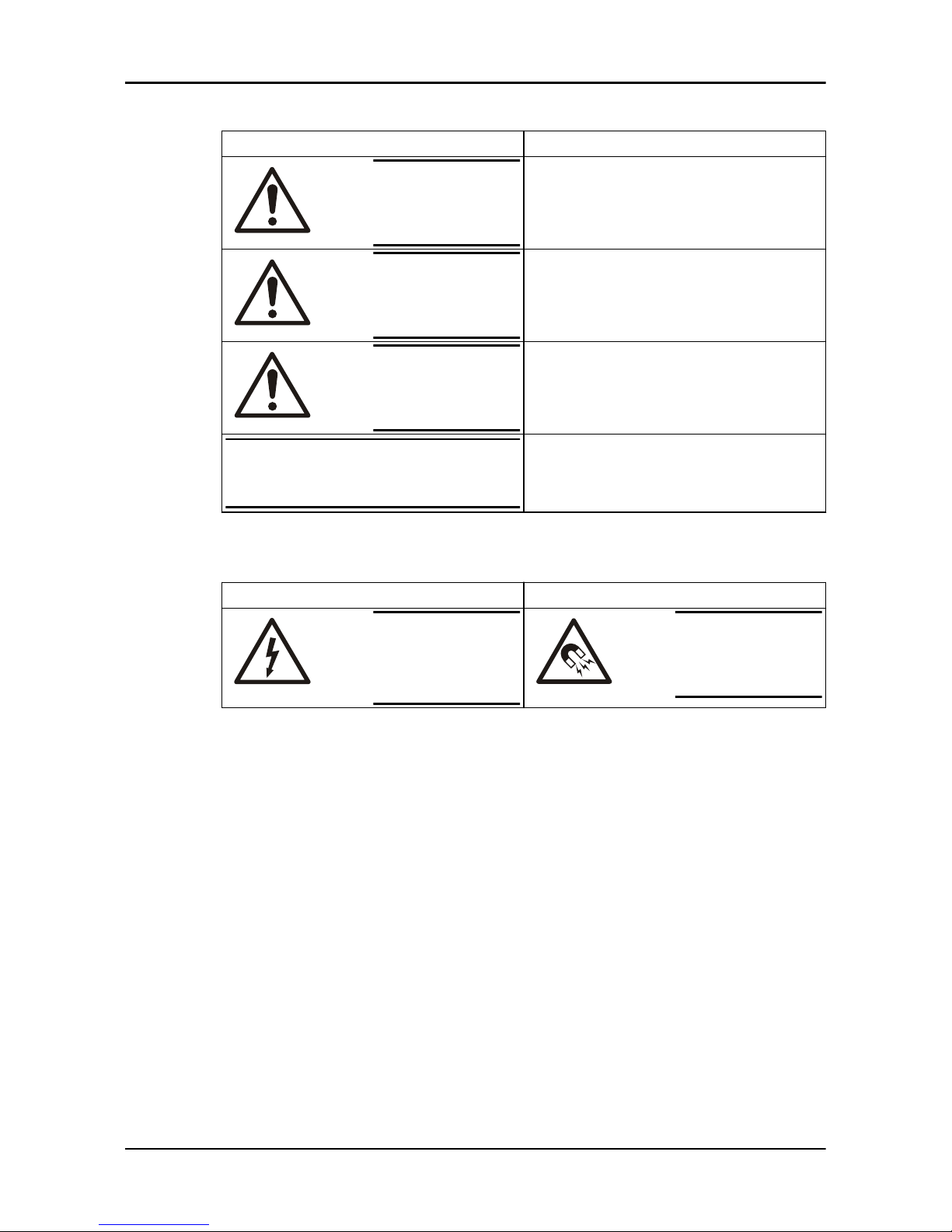
Hazard levels
Hazard level Indication
DANGER:
A hazardous situation which, if not avoided, will
result in death or serious injury
WARNING:
A hazardous situation which, if not avoided, could
result in death or serious injury
CAUTION:
A hazardous situation which, if not avoided, could
result in minor or moderate injury
NOTICE:
Notices are used when there is a risk of equipment
damage or decreased performance, but not
personal injury.
Special symbols
Some hazard categories have specific symbols, as shown in the following table.
Electrical hazard Magnetic fields hazard
Electrical
Hazard:
CAUTION:
1.3 User safety
Introduction
All government regulations, local health and safety directives must be observed.
Prevent danger due to electricity
All danger due to electricity must be avoided. Electrical connections must
always be carried out in compliance with the following:
• The standard connections shown in the product documentation that is
delivered together with the product
• All international, national, state, and local regulations. (For details, consult
the regulations of your local electricity supplier.)
For more information about requirements, see sections dealing specifically with
electrical connections.
1 Introduction and Safety
4 FST Installation, Operation, and Maintenance Manual
Page 7
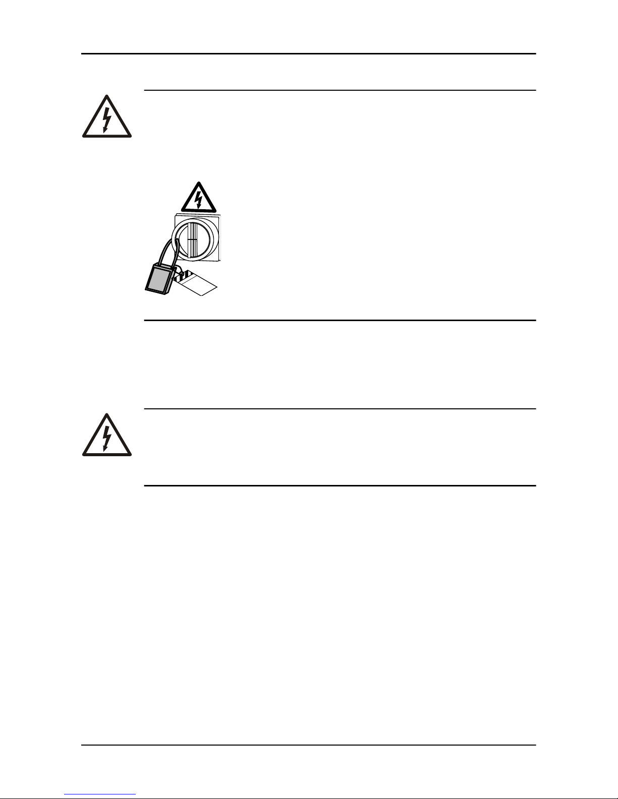
1.3.1 Power lock-out
DANGER: Electrical Hazard
Before starting work on the unit, make sure that the unit and the
control panel are isolated from the power supply and cannot be
energized. This applies to the control circuit as well.
Equipment
locked out by
Name .......................
DANGER
1.3.1.1 Battery
Check that the cable has been disconnected from the negative battery terminal,
as part of the power lock-out process.
1.3.2 Qualification of personnel
WARNING: Electrical Hazard
Risk of electrical shock or burn. A certified electrician must
supervise all electrical work. Comply with all local codes and
regulations.
All work on the product must be carried out by certified electricians or Xylem
authorized mechanics.
Xylem disclaims all responsibility for work done by untrained, unauthorized
personnel.
1.4 End of life product disposal
Handle and dispose of all waste in compliance with local laws and regulations.
1 Introduction and Safety
FST Installation, Operation, and Maintenance Manual 5
Page 8
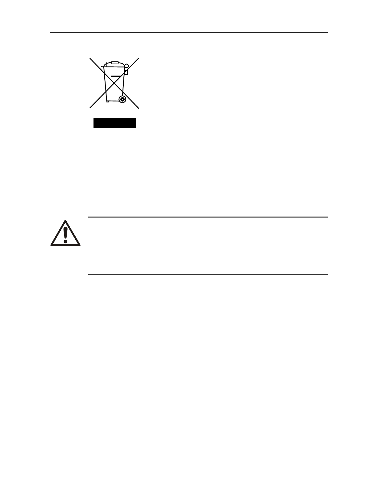
EU only: Correct disposal of this product — WEEE Directive on waste electrical and electronic
equipment
WS009973A
This marking on the product, accessories or literature indicates that the product
should not be disposed of with other waste at the end of its working life.
To prevent possible harm to the environment or human health from
uncontrolled waste disposal, please separate these items from other types of
waste and recycle them responsibly to promote the sustainable reuse of
material resources.
Waste from electrical and electronic equipment can be returned to the
producer or distributor.
1.5 Spare parts
CAUTION:
Only use the manufacturer’s original spare parts to replace any
worn or faulty components. The use of unsuitable spare parts
may cause malfunctions, damage, and injuries as well as void
the warranty.
1.6 Warranty
For information about warranty, see the sales contract.
1.7 Support
Xylem only supports products that have been tested and approved. Xylem does
not support unapproved equipment.
1 Introduction and Safety
6 FST Installation, Operation, and Maintenance Manual
Page 9
2 Product Description
2.1 Introduction
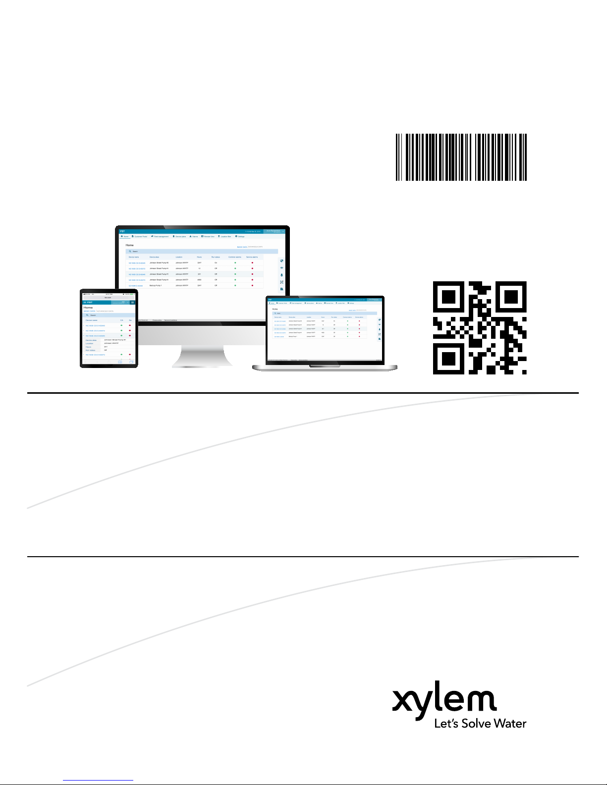
The FST module collects the engine and the pump data. This data is transmitted
to the cloud application for view, monitor, and data log purposes.
The FST application shows the same information that shows on the PrimeGuard
2 or PV102P control panel.
The module communicates through cellular and satellite networks.
The application allows the pump engine to start and stop from a remote
location.
2.2 Features
• Monitor the engine and pump parameters for the following functions:
– Remote troubleshooting with the ECU codes
– Ensure a correct system operation
– Bypass without a pump monitoring
• Start, stop, and vary the engine speed from a remote location for the
improved system control
• Allow cellular and satellite communication
• Log data and hours for an accurate and easy reporting
• Send alarm notification for on or off, and failure of the engine
• Send automatic geofence alerts with a streamlined tracking
• Manage equipment from a single platform, and integrate with asset
management software
2.3 Parts
1
2
4
3
6
7
8
5
WS011147A
2 Product Description
FST Installation, Operation, and Maintenance Manual 7
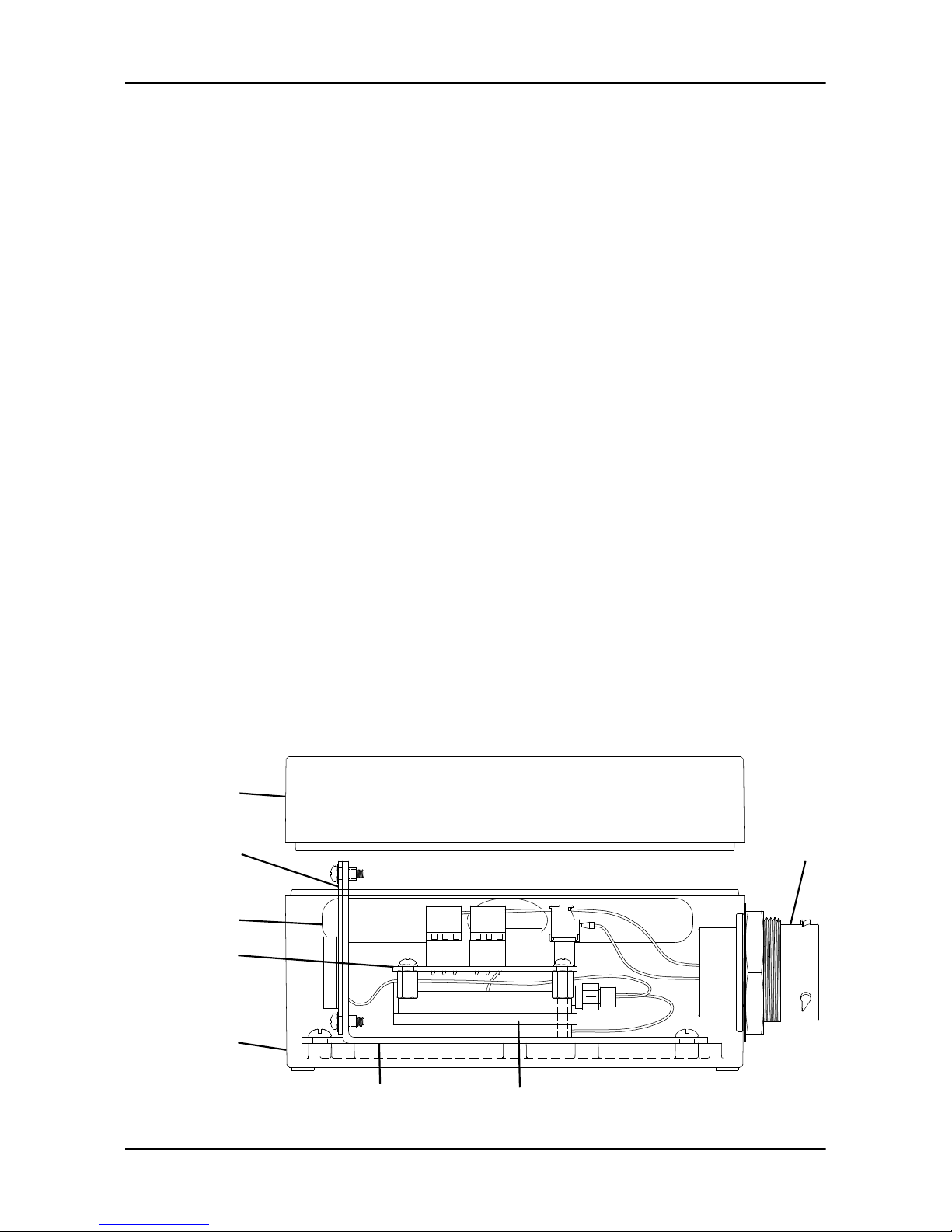
Page 10

1. FST module
2. FST module cover
3. 21-pin connector
4. Satellite antenna
5. Cellular antenna
6. PCB assembly
7. Modem
8. Mounting bracket
2.4 Extra parts
Part number Item Description
Optional MJK flowmeter Connects with the PrimeGuard 2 and PV102P
control panel to measure the flow of the liquid
Optional Suction pressure transducer Connects with the PrimeGuard 2 and PV102P
control panel to measure the suction pressure
in psi
Optional Discharge pressure
transducer
Connects with the PrimeGuard 2 and PV102P
control panel to measure the discharge
pressure in psi
Optional Fuel level transducer Connects with the PrimeGuard 2 and PV102P
control panel to measure the fuel level in %
Optional Sump level transducer Connects with the PrimeGuard 2 and PV102P
control panel to measure the sump level in ft
Optional Vibration sensor Connects with the I/O extension cable to
measure the vibration
FSTWIREHARNESS Wiring harness for the FST
module
Connects the FST module and the control panel
FSTIOEXTCABLE I/O extension cable for the
FST module
Connects digital input and analog input
devices such as floats, flowmeters, transducers
to the FST module
4000174 Pigtail harness Connects with the PrimeGuard 2 control panel
GPFSTBRKT Mounting bracket Used to install the FST module on the pump
engine enclosure
2902829 Signal isolator Used to connect the flowmeter to the
PrimeGuard 2 and PV102P control panel
2 Product Description
8 FST Installation, Operation, and Maintenance Manual
Page 11

3 Mechanical Installation
3.1 Precautions
Before starting work, make sure that the safety instructions in the chapter
Introduction and Safety on page 3 have been read and understood.
3.2 Prepare for an open engine unit
1. Drill a 6.35 mm (0.25 in) diameter hole at a distance of 127 mm (5 in) from
the lifting bail plate.
2. Drill one more 6.35 mm (0.25 in) diameter hole at a distance of
57.15 mm (2.25 in) from the first hole.
127 mm
(5 in)
57.15 mm
(2.25 in)
∅ 6.35 mm
(0.25 in)
WS011176A
3.3 Prepare for an enclosed engine unit
1. Drill two 6.35 mm (0.25 in) diameter holes as high as possible on the
enclosure.
3 Mechanical Installation
FST Installation, Operation, and Maintenance Manual 9
Page 12
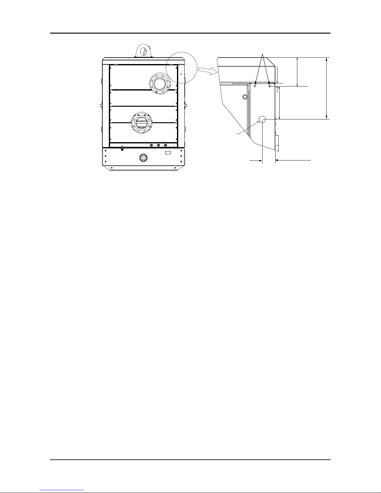
WS011189A
∅ 6.35 mm
(0.25 in)
127 mm
(5 in)
12.7 mm
(0.5 in)
50.8 mm
(2 in)
111.1 mm
(4.375 in)
238.1 mm
(9.375 in)
∅ 25.4 mm
(1 in)
2. Drill a 25.4 mm (1 in) diameter hole 127 mm (5 in) below the
6.35 mm (0.25 in) diameter holes.
3. Install a cable gland or a grommet on the 25.4 mm (1 in) diameter hole.
4. Route the cable harness through the 25.4 mm (1 in) hole.
3.4 Install the FST module
1. Install the following on the mounting frame:
– the mounting bracket
– the two flat washers
– the two hexagon head bolts
2. Install the four isolators on the mounting bracket.
3. Install the FST module on the four isolators.
4. Tighten the four hexagon nuts on the isolators.
3 Mechanical Installation
10 FST Installation, Operation, and Maintenance Manual
Page 13
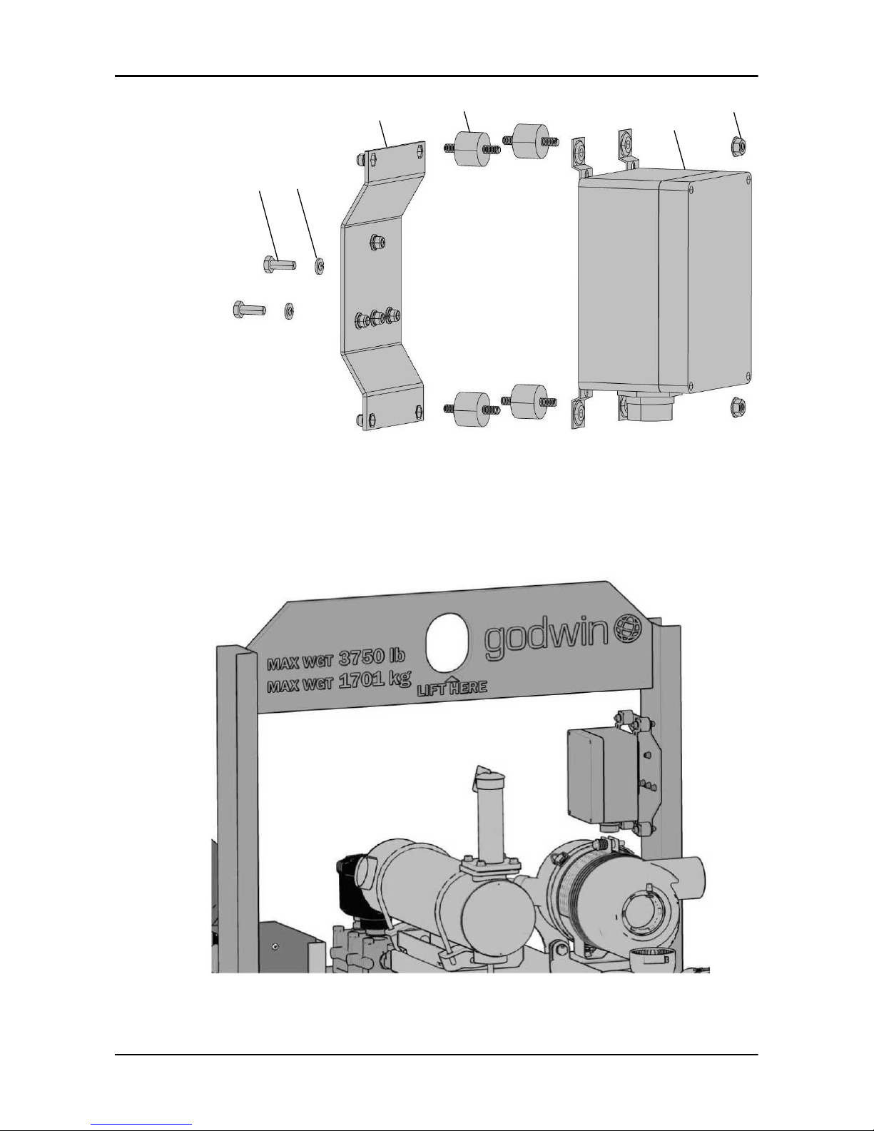
1
2
3
4
5
6
WS011188A
1. Hexagon head screw
2. Flat washer
3. Mounting bracket
4. Isolator
5. FST module
6. Hexagon nut
Figure 1: Installation of the FST module
WS011191A
Figure 2: Installation of the FST module on an open unit
3 Mechanical Installation
FST Installation, Operation, and Maintenance Manual 11
Page 14
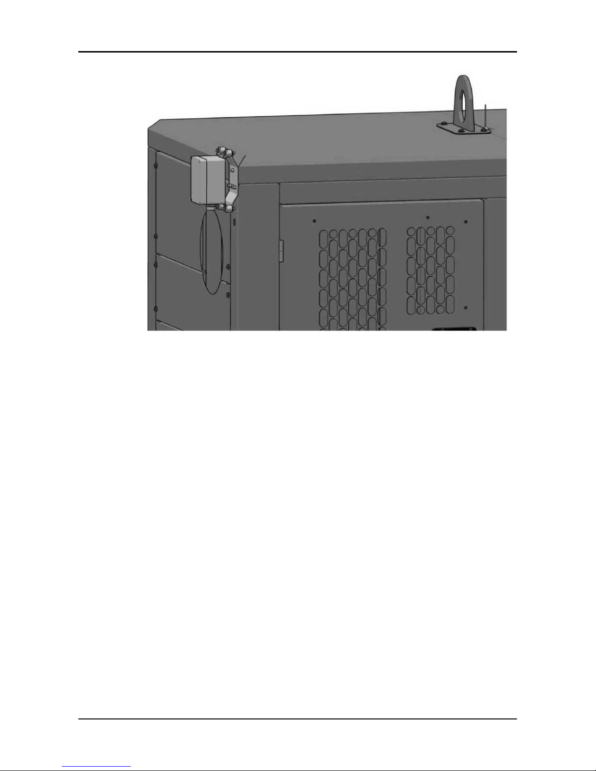
WS011190A
Figure 3: Installation of the FST module on an enclosed unit
3 Mechanical Installation
12 FST Installation, Operation, and Maintenance Manual
Page 15

4 Electrical Installation
4.1 Precautions
Before starting work, make sure that the safety instructions in the chapter
Introduction and Safety on page 3 have been read and understood.
DANGER: Electrical Hazard
Before starting work on the unit, make sure that the unit and the
control panel are isolated from the power supply and cannot be
energized. This applies to the control circuit as well.
DANGER: Crush Hazard
Moving parts can entangle or crush. Always disconnect and lock
out power before servicing to prevent unexpected startup.
Failure to do so could result in death or serious injury.
WARNING: Electrical Hazard
Risk of electrical shock or burn. A certified electrician must
supervise all electrical work. Comply with all local codes and
regulations.
WARNING: Electrical Hazard
There is a risk of electrical shock or explosion if the electrical
connections are not correctly carried out, or if there is fault or
damage on the product. Visually inspect equipment for
damaged cables, cracked casings or other signs of damage.
Make sure that electrical connections have been correctly
made.
CAUTION: Electrical Hazard
Prevent cables from becoming sharply bent or damaged.
4.1.1 Battery
Check that the cable has been disconnected from the negative battery terminal,
as part of the power lock-out process.
4.2 Cables
These requirements apply for cable installation:
4 Electrical Installation
FST Installation, Operation, and Maintenance Manual 13
Page 16

• The cables must be in good condition, not have any sharp bends, and not be
pinched.
• The sheathing must not be damaged and must not have indentations or be
embossed at the cable entry.
• The minimum bending radius must not be below the accepted value.
• The cables must have the appropriate temperature rating.
4.3 Connect the wiring harness to the control panel
1. Connect the female circular connector of the wiring harness to the FST
module.
2. Connect the spliced terminals of the wiring harness to the control panel.
Wire color
Control panel
PrimeGuard 2
terminal
PV102P terminal Description
Orange Key switch Batt Key switch Batt V+
Black 15 6, 7, and 8 BATT-
Brown 12 14 DIG IN 1
Green 19 10 CAN LO
Yellow 20 11 CAN HI
Red 14 18 BATT +
White 4 12 RS 485 L
Blue 3 13 RS 485 H
4 Electrical Installation
14 FST Installation, Operation, and Maintenance Manual
Page 17

IGN
ST
BAT
ACC
WS011137A
1
2
3
4
1. Circular connector, connects to the FST module
2. Wiring harness for the FST module
3. Key switch
4. Control panel
4.4 Connect the I/O extension cable
1. Connect the female connector of the I/O extension cable to the FST module.
2. Connect the other connector of the I/O extension cable to the circular
connector of the wiring harness.
3. Connect the spliced terminals of the wiring harness to the control panel.
For more information regarding pin connection, see Connect the wiring
harness to the control panel on page 14.
4. As applicable, connect the spliced terminals of the I/O extension cable to the
following:
– Relays
– Analog signal devices
– Digital signal devices
4 Electrical Installation
FST Installation, Operation, and Maintenance Manual 15
Page 18

1
2
3
4
5
WS011260A
6
7
1. FST module
2. I/O extension cable for the FST module
3. Wiring harness for the FST module
4. Control panel
5. Spliced terminals that connect to relays, analog signal devices, or digital signal
devices
6. HDP26 connector
7. HDP24 connector
4.5 Connect a flowmeter to the control panel
1. Connect the signal isolator to the control panel.
2. Set the DIP switch 7 to the ON position.
3. Connect the signal isolator to a flowmeter.
Wire color Flowmeter Signal isolator
Red wire Analog output + I+
Black wire Analog output - GND
4 Electrical Installation
16 FST Installation, Operation, and Maintenance Manual
Page 19

+
-
4-20mA+
4-20mA-
BATT V+ IN
I+ OUT TO AI4
WS011138A
3
2
1
4
5
4
3
U
U+ IN
PWR IN
GND
5
6
PASSIVE
I OUT
I+ IN
1
2
GND
1. Flowmeter
2. Signal isolator
3. Control panel
4. Red wire
5. Black wire
4. Set the parameters for the flowmeter on the control panel.
See Set the parameters for the flowmeter on page 26.
4.6 Connect the suction pressure transducer
1. Connect the suction pressure transducer to the control panel.
4 Electrical Installation
FST Installation, Operation, and Maintenance Manual 17
Page 20

WS011139A
1
2
3
4
1. Suction pressure transducer
2. Control panel
3. Red wire
4. Black wire
2. Set the parameters for the suction pressure transducer on the control panel.
See Set the parameters for the suction pressure transducer on page 26.
4.7 Connect the discharge pressure transducer
1. Connect the discharge pressure transducer to the control panel.
4 Electrical Installation
18 FST Installation, Operation, and Maintenance Manual
Page 21

WS011140A
1
2
3
4
1. Discharge pressure transducer
2. Control panel
3. Red wire
4. Black wire
2. Set the parameters for the discharge pressure transducer on the control
panel.
See Set the parameters for the discharge pressure transducer on page 26.
4.8 Connect a fuel level transducer
Select a fuel level transducer
1. Remove the fuel gauge from the fuel tank.
2. Insert a measuring tape into the fuel tank from the fuel gauge opening.
3. Measure from the bottom of the fuel tank to the top of the fuel gauge
opening.
4 Electrical Installation
FST Installation, Operation, and Maintenance Manual 19
Page 22

WS011258A
1
3
2
1. Fuel tank
2. Fuel fill
3. Fuel gauge
4. Record the measurement.
The height of the sensor blade of the fuel level transducer must be slightly
smaller than the depth of the tank.
5. To determine the height of the sensor blade, subtract 31.75 mm (1.25 in)
from the recorded measurement.
WS011259A
1
2
1. Fuel level transducer
2. Height of the sensor blade
6. Use the result from the step 5 to select a fuel level transducer from the
following list.
Fuel level transducer Godwin part number
14.5" 1‐1/2" NTP resistive fuel level transducer ACT‐10897
13.5" 1‐1/2" NTP resistive fuel level transducer ACT‐10898
4 Electrical Installation
20 FST Installation, Operation, and Maintenance Manual
Page 23

Fuel level transducer Godwin part number
11.5" 1‐1/2" NTP resistive fuel level transducer ACT‐10899
10.5" 1‐1/2" NTP resistive fuel level transducer ACT‐10900
9.5" 1‐1/2" NTP resistive fuel level transducer ACT‐10901
8.5" 1‐1/2" NTP resistive fuel level transducer ACT‐10902
7.5" 1‐1/2" NTP resistive fuel level transducer ACT‐10903
6.5" 1‐1/2" NTP resistive fuel level transducer ACT‐10904
34" 1‐1/2" NTP resistive fuel level transducer ACT‐10922
Connect the fuel level transducer to the control panel
1. Remove the existing fuel gauge from the fuel tank.
2. Apply the Teflon tape to the fuel level transducer.
3. Tighten the fuel level transducer into the 1.5” FNPT port.
4. Pass the red wire and the black wire through the cable gland on the bottom
of the control panel where the FST harness enters.
5. To open the control panel, remove the top two screws above the display
screen.
6. Connect the fuel level transducer to the control panel.
WS011292A
1
2
3
4
1. Fuel level transducer
2. Control panel
3. Red wire
4. Black wire
4 Electrical Installation
FST Installation, Operation, and Maintenance Manual 21
Page 24

7. Close the control panel and tighten the two screws again.
8. Set the parameters for the fuel level transducer on the control panel.
See Set the parameters for the fuel level transducer on page 26.
4.9 Connect the sump level transducer
1. Connect the sump level transducer to the 7-pin connector of the pigtail
harness.
2. Connect the other connector of the pigtail harness to the 7-pin connector of
the control panel.
WS011282A
1
354
4-20mA input
Batt +
Batt -
NO start switch
NC stop switch
Low lube oil
Low coolant
1
2
3
4
6
7
5
2
1. Sump level transducer
2. 7-pin connector of the pigtail harness
3. Red wire
4. Black wire
5. Shield
3. Set the parameters for the sump level transducer on the control panel.
See Set the parameters for the sump level transducer on page 27.
4.10 Connect devices to IO extension cable
Connect 4-20 mA field sensors
1. Connect a passive 4-20 mA field sensor to the AI1 spliced terminals of the
I/O extension cable.
This sensor is not externally powered. It requires power from FST.
2. Connect an active 4-20 mA field sensor to the AI2 spliced terminals of the
I/O extension cable.
This sensor is externally powered. It does not require power from FST.
4 Electrical Installation
22 FST Installation, Operation, and Maintenance Manual
Page 25

WS011283A
5
7
V+
AI1
GND
3
6
2
5
V+
AI2
GND
6
1
4
1. Passive 4-20 mA sensor
2. Active 4-20 mA sensor
3. AI1 spliced terminals of the I/O extension cable
4. AI2 spliced terminals of the I/O extension cable
5. Red wire
6. Black wire
7. Shield
Connect the float switches
Connect a float switch to the DI1 or DI2 spliced terminals of the I/O
extension cable.
WS011300A
DI1
DI1 COM
DI2
DI2 COM
NO
NC
Connect relays
As applicable, connect 120VAC, 5A device R1 and R2 spliced terminals of
the I/O extension cable.
R1 COM and NO R2 COM and NO R2 COM and NC
5 A @ 30 VDC 5 A @ 30 VDC 5 A @ 30 VDC
xA @ 120 VAC xA @ 120 VAC xA @ 120 VAC
yA @ 240 VAC yA @ 240 VAC yA @ 240 VAC
4 Electrical Installation
FST Installation, Operation, and Maintenance Manual 23
Page 26

WS011303A
NO
NO
COM
COM
NC
1
1
1. 120VAC, 5A devices
4 Electrical Installation
24 FST Installation, Operation, and Maintenance Manual
Page 27

5 System Setup
Introduction
The following configurations are done on the PrimeGaurd 2 control panel.
For the PV102P configuration parameters, refer to PV102P control panel
documentation.
5.1 Set the communication parameters
1. Go to MAIN PARAMETERS > COMMUNICATION PARAMETERS.
2. Set the communication parameters:
Parameter Setting
MODBUS SERVER ADDRESS 247
RS485 SERVER BAUD RATE 38400
PROTOCOL SELECTION Modbus
5.2 Set the miscellaneous parameters
1. Go to MAIN PARAMETERS > MISCELLANEOUS PARAMETERS.
2. Set the miscellaneous parameters:
Parameter Setting
Mechanical Engines None
Electronic Engine J1939 PrimeGuard HRS or J1939 ECU Engine HRS
5.3 Set the digital input parameter
1. Go to MAIN PARAMETERS > DIGITAL INPUT PARAMETERS.
2. Set the digital input parameter:
Control panel Parameter Setting
PrimeGuard 2 DIGITAL INPUT 1 Remote call to run
PV102P DIGITAL INPUT 4 Remote call to run
This parameter is used to start and stop the pump remotely.
5.4 Set the analog input parameters
1. Go to MAIN PARAMETERS > ANALOG INPUT PARAMETERS.
2. Set the following analog input parameters.
These parameters are used for optional devices that are pressure
transducers and flowmeters.
5 System Setup
FST Installation, Operation, and Maintenance Manual 25
Page 28

Set the parameters for the flowmeter
1. Select the ANALOG INPUT 4 parameter.
2. Select the 4-20 mA FLOW RATE parameter.
3. Set the following values:
Value Setting
0 4.00 mA
Max Maximum flow of the 4-20 mA signal from the flowmeter
The default flow values for the MJK 7200 series flowmeters are as follow:
Diameter, in Flow, gpm
3 800
4 1000
6 3000
8 5000
10 8000
12 10000
18 25000
24 40000
36 100000
48 200000
Set the parameters for the suction pressure transducer
1. Select the ANALOG INPUT 6 parameter.
2. Select the 4-20 mA SUCTION PRESSURE parameter.
3. Set the following values for the applicable transducer:
Value
PXTK30v30
30 inHg to 30 psi
PXTK30v60
30 inHg to 60 psi
PXTK30v100
30 inHg to 100 psi
Vacuum transducer
0 9.26 mA 7.14 mA 6.04 mA 4 mA
Max 30 psi 60 psi 100 psi 14.7 psi
Set the parameters for the discharge pressure transducer
1. Select the ANALOG INPUT 7 parameter.
2. Select the 4-20 mA DISCHARGE PRESSURE parameter.
3. Set the following values:
Value Setting
0 4.00 mA
Max Maximum pressure of the discharge pressure transducer in psi
Set the parameters for the fuel level transducer
1. Select the ANALOG INPUT 3 > MURPHY FUEL LEVEL parameter.
2. Press NEXT to return to the main screen.
5 System Setup
26 FST Installation, Operation, and Maintenance Manual
Page 29

3. Select the ENGINE PARAMETERS > FUEL LOW WARNING parameter.
4. Set the necessary percentage level with the up and down arrow key.
5. Press ENTER.
6. Select the ENGINE PARAMETERS > FUEL LOW SHUTDOWN parameter.
7. Set the necessary percentage level with the up and down arrow key.
8. Press ENTER.
9. Press NEXT to return to the main screen.
Set the parameters for the sump level transducer
1. Go to OPERATION PARAMETERS > OPERATION MODE.
2. Select the MANUAL/AUTO NO WARNING mode.
3. Then, go to MAIN PARAMETERS > PUMP CONTROL PARAMETERS >
START/STOP TYPE.
4. Select the LEVEL > START LEVEL parameter.
5. To automatically start the pump, set the high level of sump with the up and
down arrow key.
6. Press ENTER.
7. Select the LEVEL > STOP LEVEL parameter.
8. To automatically start the pump, set the low level of sump with the up and
down arrow key.
9. Press ENTER.
10. Select the LEVEL > MAINTAIN LEVEL parameter.
11. Make sure that the maintain ft level is less than the stop level. Adjust as
necessary.
12. Go to MAIN PARAMETERS > ANALOG INPUT PARAMETERS.
13. Select the ANALOG INPUT 5 parameter.
14. Set the following values:
Value Setting
ZERO OFFSET 4.00 mA
MAX Maximum value of the level transducer in ft.
Sump level transducers are typically rated in psi, which is displayed on the
transducer. The psi rating of the sump level transducer must be converted
to feet.
Example: 15 psi transducer x 2.31 = 35 feet.
15. Press NEXT to return to the main screen.
16. Set the key to OFF to set parameters in the controller memory.
5 System Setup
FST Installation, Operation, and Maintenance Manual 27
Page 30

6 Operation
Start the application
1. Start the FST application at http://cloud.xylem.com.
2. Enter the user name and password to log on.
6.1 Home
This tab shows the basic and the advance pump data, the location of the pump,
and the alarm status.
6.1.1 View the device data
• View the basic data
a) On the Home page, click the BASIC DATA tab.
b) To view the device alarm details, click the Common alarms or Service
alarms icon.
The application shows the Alarm manager page.
c) To view the control panel of a specific device, click the device name.
The application shows the Control panel page.
• View the advanced data
a) On the Home page, click the ADVANCED DATA tab.
b) To view the device alarm details, click the Common alarms or Service
alarms icon.
The application shows the Alarm manager page.
c) To view the control panel of a specific device, click the device name.
The application shows the Control panel page.
6.2 Customer portal
This tab allows the download of customer documents, for example, rental
contract, and sales order.
6.2.1 Download customer documents
1. Click the Customer portal tab.
2. Select one of the following document types:
Document type Description
Rental contract Shows the rental contract report for the selected document
number
Sales order Shows the report of the service plans for the selected
document number
3. Select the document number from the list.
4. Click Submit.
The application shows the details of the selected document.
5. Click the FST service plan icon.
6 Operation
28 FST Installation, Operation, and Maintenance Manual
Page 31

The application shows the Service plan page of the device.
6.3 Fleet management
This tab shows devices, their owners, other devices that integrate with pumps,
and the device location.
6.3.1 Change device details
1. Click the Fleet management tab.
2. On the Fleet management page, click the device name.
3. If applicable, in the Device alias text box, change the device name.
4. Click Next.
5. If applicable, change the following locations:
– Region
– Hub
– Customer
– Site
6. Click Save.
6.4 Service plans
6.4.1 Configure a service plan
1. Click the Service plans tab.
2. In the Device name list, select the device to configure the service plan.
3. Select one or more of the following service plans:
Service plans Description
FST base plan Gives access to the basic features of the FST
This service must be selected to select the other services
Advanced data access and
Data log access
Gives access to the ADVANCED DATA tab and the Data log page
Remote control Gives access to the Control panel page
Satellite connectivity Gives access to the Remote view tab
Interactive telephone
alarming
Gives access to configure the telephone and SMS alarm notifications
4. To include the selected services in the service plan, click Continue.
5. To discontinue the existing service plan, click Discontinue.
6. To reset the service plan, click Reset.
6.5 Alarms
6.5.1 Acknowledge an alarm
1. Click the Alarms tab.
2. In the Device name list, select the device to acknowledge the alarm.
3. Select the acknowledge icon.
6 Operation
FST Installation, Operation, and Maintenance Manual 29
Page 32

The following information replaces the acknowledge icon:
– Date and time of the alarm acknowledgment
– Person who acknowledged the alarm
6.5.2 View Service Advisor
1. Click the Alarms tab.
2. In the Device name list, select the device to view the service advisor.
3. Click the Service advisor icon.
The application shows the corrective action information.
6.6 Remote view
This tab shows the device location in the map view.
The click on the balloon icon shows the device details.
6.7 Location filter
6.7.1 Filter the locations
1. Select one or more regions from the Region list.
The Hub list is shown.
2. If necessary, select one or more hubs from the Hub list.
The Customer list is shown.
3. If necessary, select one or more customers from the Customer list.
The Site list is shown.
4. If necessary, select one or more sites from the Site list.
5. Click Save.
The location filter is applied for the selected locations.
6.8 Settings
6.8.1 User administration
6.8.1.1 View the users list
1. Click the Settings tab.
2. On the Settings page, click the User administration button.
The User administration page shows the user details, for example, name,
contact information, location assignment, and role.
6.8.1.2 Change the user details
1. Click the Settings tab.
2. On the Settings page, click the User administration button.
3. On the User administration page, click the user to change the details.
4. On the Edit user page, change the details as applicable.
5. Click the Update button.
6 Operation
30 FST Installation, Operation, and Maintenance Manual
Page 33

6.8.1.3 Create a user
1. Click the Settings tab.
2. On the Settings page, click the User administration button.
3. On the User administration page, click the Create user button.
4. In the Create user page, type the name, email, and phone number of the
user in the respective text box.
5. In the Location assignment list, select one of the following locations:
Service plan Description
Region This location is a logical grouping of the hubs.
The group of hubs define the geographic location of the region.
Customer This location is a business entity that has a physical address, billing address,
and account number.
Usually, the entity pays for the features and services.
It is possible for customers to temporarily own the devices.
It must have a geographic location.
Hub This location is the owner of a device.
It is a customer or a Xylem location.
It must have a geographic location.
The hub pays for the services and features.
Site This location is a physical location where devices are installed permanently or
temporarily.
It must have a geographic location.
6. In the Individual rights check box, select the following user rights as
applicable:
Service plan Description
FST access Gives access to the basic features of the FST
FST admin Gives the FST administrator rights
Service advisor Gives access to the Service advisor page
Alarm notification Gives access to the Alarms page in the Settings tab
Control panel
access
Gives access to the Control panel page
Advance data log
access
Gives access to the ADVANCE DATA tab and the Data log page
7. In the Time zone list, select the time zone for the user.
8. In the Units list, select one of the following units:
– SAE
– Metric
9. Click Save.
6 Operation
FST Installation, Operation, and Maintenance Manual 31
Page 34

6.8.2 Device administrator
6.8.2.1 Manage devices
1. Click the Settings tab.
2. On the Settings page, click the Device administrator button.
3. On the Device management page, click the device to change the details.
4. If applicable, in the Device alias text box, change the device name.
5. Click Next.
6. If applicable, change the following locations:
– Region
– Hub
– Customer
– Site
7. Click Save.
6.8.3 Location administration
6.8.3.1 View the locations list
1. Click the Settings tab.
2. On the Settings page, click the Location administration button.
The Location administration page shows the lists of regions, hubs,
customers, and sites.
3. In the Search Region, Search Hub, Search Customer, or Search Site box, type
the name of the location to search.
6.8.3.2 Create a region
1. Click the Settings tab.
2. On the Settings page, click the Location administration button.
3. On the Location administration page, select the Region column header.
The Create button is enabled.
4. Click the Create button.
5. On the Create new region page, type a region name.
6. In the Associated hubs list, select one or more hub names to associate with
the region.
7. Click Create.
6.8.3.3 Create a hub
1. Click the Settings tab.
2. On the Settings page, click the Location administration button.
3. On the Location administration page, select the Hub column header.
The Create button is enabled.
4. Click the Create button.
6 Operation
32 FST Installation, Operation, and Maintenance Manual
Page 35

5. On the Create new hub page, type a hub name.
6. Type the hub ID.
7. Type the hub address.
8. In the Xylem Service Center list, select a service center for the hub.
9. In the Associated customers list, select one or more customer names to
associate with the hub.
10. In the Financial contact email text box, type the email address.
11. In the Contact number text box, type the telephone number.
12. Click Create.
6.8.3.4 Create a customer
1. Click the Settings tab.
2. On the Settings page, click the Location administration button.
3. On the Location administration page, select the Customer column header.
The Create button is enabled.
4. Click the Create button.
5. On the Create new customer page, type a customer name.
6. Type the customer ID.
7. Type the customer address.
8. In the Xylem Service Center list, select a service center for the customer.
9. In the Associated sites list, select one or more site names to associate with
the customer.
10. In the Financial contact email text box, type the email address.
11. In the Contact number text box, type the telephone number.
12. Click Create.
6.8.3.5 Create a site
1. Click the Settings tab.
2. On the Settings page, click the Location administration button.
3. On the Location administration page, select the Site column header.
The Create button is enabled.
4. Click the Create button.
5. On the Create new site page, type a site name.
6. Type the site ID.
7. Type the site address.
8. In the Xylem service center list, select a service center for the site.
9. In the Financial contact email text box, type the email address.
10. In the Contact number text box, type the telephone number.
11. Click Create.
6 Operation
FST Installation, Operation, and Maintenance Manual 33
Page 36

6.8.3.6 View or change the location details
1. Click the Settings tab.
2. On the Settings page, click the Location administration button.
3. On the Location administration page, select the name of the location from
the following lists to change details:
– Region
– Hub
– Customer
– Site
4. On the edit location page, change the location details as applicable.
5. Click the Update button.
6.8.3.7 Delete a location
1. Click the Settings tab.
2. On the Settings page, click the Location administration button.
3. On the Location administration page, select the name of the location from
the following lists to delete:
– Region
– Hub
– Customer
– Site
4. On the edit location page, click Delete.
6.8.4 Input output
6.8.4.1 Configure input output devices
1. Click the Settings tab.
2. On the Settings page, click the Input/Output admin button.
3. On the Input output configuration page, select the device name.
4. For the Digital input 1, select the input type and alarm status.
5. For the Digital input 2, select the input type and alarm status.
6. Click Next.
7. Set the Analog input 1 parameters.
8. Click Next.
9. Set the Analog input 2 parameters.
10. Click Next.
11. Select the values for the Output relay 1 and the Output relay 2.
This is for switching 120VAC, 5A devices. One relay is normally open and
the other is normally open and normally closed.
12. Click Save.
6 Operation
34 FST Installation, Operation, and Maintenance Manual
Page 37

6.8.5 Alarm administration
6.8.5.1 Manage alarms
1. Click the Settings tab.
2. On the Settings page, click the Alarm admin button.
3. On the Alarm manager page, select the device name.
4. In the Delay list, select a delay time.
5. In the Recipient name list, select a recipient.
6. In the Delivery method list, select one or more of the following delivery
methods:
– Text message
– Email
7. In the Alarm type list, select one or more of the following alarm types:
– Common alarms
– Service maintenance alarm
– Pump start
– Pump stop
– Analog input 1
– Analog input 2
– Digital input 1
– Digital input 2
8. To add one more recipient, click the Add another recipient button.
9. Click Save.
6.9 Right navigation pane
Icon Type Description
User administration Read-only Shows access to the User administration page
FST access Read-only Shows access to the FST access page
Service advisor Read-only Shows access to the Service advisor page
Control panel Clickable Shows access to the Control panel page
For more information, see Operate device from a remote
location on page 35.
Data log Clickable Shows access to the Data log page
For more information, see Download device data log on
page 36.
6.9.1 Control panel
6.9.1.1 Operate device from a remote location
1. On the right navigation pane, click the Control panel menu.
2. On the Control panel page, select the device.
6 Operation
FST Installation, Operation, and Maintenance Manual 35
Page 38

3. To update the parameters that appear on the screen, click the REFRESH
button.
4. To increase the engine speed, click the SPEED INC button.
5. To decrease the engine speed, click the SPEED DEC button.
6. To start the engine, click the START button.
7. To stop the engine, click the STOP button.
8. To see the Alarms page for the selected device, click the Alarms button.
9. To see the Data log page for the selected device, click the Data log button.
6.9.2 Data log
6.9.2.1 Download device data log
1. On the right navigation pane, click the Data log menu.
2. In the Device name list, select the device.
3. Select the start date and the end date for the data log report.
4. Click Submit.
The data log report for the selected device appears.
5. Click Export to download the data log report in CSV format.
6 Operation
36 FST Installation, Operation, and Maintenance Manual
Page 39

7 Maintenance
7.1 Precautions
Before starting work, make sure that the safety instructions in the chapter
Introduction and Safety on page 3 have been read and understood.
DANGER: Electrical Hazard
Troubleshooting a live control panel exposes personnel to
hazardous voltages. Electrical troubleshooting must be done by
a qualified electrician.
DANGER: Crush Hazard
Moving parts can entangle or crush. Always disconnect and lock
out power before servicing to prevent unexpected startup.
Failure to do so could result in death or serious injury.
7.1.1 Battery
Check that the cable has been disconnected from the negative battery terminal,
as part of the power lock-out process.
7.2 Check the unit for general condition
Make sure that the unit is free from dust. Clean it by using a soft cloth.
Check the terminals for corrosion.
7.3 Replace a damaged unit
1. Disconnect the cable from the unit.
2. Remove the current unit and replace it with a new unit.
3. Follow the instructions in Install the FST module on page 10 and Connect the
wiring harness to the control panel on page 14.
4. Send the old unit back to the manufacturer.
7 Maintenance
FST Installation, Operation, and Maintenance Manual 37
Page 40

8 Troubleshooting
8.1 Precautions
Before starting work, make sure that the safety instructions in the chapter
Introduction and Safety on page 3 have been read and understood.
DANGER: Electrical Hazard
Troubleshooting a live control panel exposes personnel to
hazardous voltages. Electrical troubleshooting must be done by
a qualified electrician.
DANGER: Crush Hazard
Moving parts can entangle or crush. Always disconnect and lock
out power before servicing to prevent unexpected startup.
Failure to do so could result in death or serious injury.
8.1.1 Battery
Check that the cable has been disconnected from the negative battery terminal,
as part of the power lock-out process.
8.2 LED status
Status
Remedy
LED5 PWR
LED1 MODEM
PWR
LED2 MODBUS
COMM
On Blinks Blinks The unit is ok
On On On Call customer service: 833-677-8776
Off Off Off 1. Check the 5 A fast-acting fuse and if
necessary, replace it.
2. Check the voltage between Batt +
and Batt -.
3. If the problem persists, then return
the unit.
On Off Off 1. Disconnect the wiring harness from
the FST module.
2. Wait for 10 seconds.
3. Connect wiring harness to the FST
module.
4. Wait for 60 seconds to establish
communication.
5. If the problem persists, then return
the unit.
8 Troubleshooting
38 FST Installation, Operation, and Maintenance Manual
Page 41

Status
Remedy
LED5 PWR
LED1 MODEM
PWR
LED2 MODBUS
COMM
On Blinks Off Check that the PrimeGuard 2 or PV102P
control panel is programmed correctly.
For more information, see the
PrimeGuard 2 or PV102P configuration.
8 Troubleshooting
FST Installation, Operation, and Maintenance Manual 39
Page 42

9 Technical Reference
9.1 Dimensions
1
3
2
WS011097A
Item Dimension
1 119.5 mm (4.7 in)
2 97.8 mm (3.85 in)
3 222 mm (8.74 in)
9.2 Weight
• 0.82 kg (1.8 lb)
9.3 Environmental requirements
Feature Value
Operating temperature -40°C to +85°C (-40°F to +185°F)
Storage temperature -50°C to +85°C (-58°F to +185°F)
Operating humidity 95% relative humidity, non-condensing
9.4 Standards
• NEMA 4X enclosure
9.5 Approvals
• CE
9.6 Electrical data
Feature Description
Supply voltage 9 VDC to 30 VDC
Power consumption 12 VDC
Sleep mode 25 µA
GSM transmission 200 mA nominal
Satellite transmission 1000 mA nominal
9 Technical Reference
40 FST Installation, Operation, and Maintenance Manual
Page 43

9.7 Communications
GSM and GPRS
Band Quad
GSM frequency 850 MHz, 900 MHz, 1800 MHz, and 1900 MHz
Server SMTP, POP3, SMS, TCP, UDP, and FTP
Satellite
Transmission frequency 1616 MHz to 1626.5 MHz
Transmission power 2 W
Packet size Tx 340 bytes, Rx 270 bytes
9.8 Connector terminals
1
2
3
4
5
6
7
8
9
10
11
12
13
14
15
16
17
18
19
20
21
WS011098A
Figure 4: Terminals of the FST circular connector
Function Terminal Description
Input power 1 9 VDC to 30 VDC
2 Ground (earth)
Digital input 6 Sleep mode
3 Digital input 1
NC Ground (earth)
10 Digital input 2
NC Ground (earth)
5 A relay, no contacts 11 Relay 1 - NO
12 Relay 1 - COM
13 Relay 2 - NO
14 Relay 2 - COM
15 Solid state relay (SSR), 130 mA
9 Technical Reference
FST Installation, Operation, and Maintenance Manual 41
Page 44

Function Terminal Description
4-20 mA 1 16 VBAT fused, 50 mA
17 4-20 mA input 1
18 Ground (earth)
4-20 mA 2 19 VBAT fused, 50 mA
20 4-20mA input 2
21 Ground (earth)
RS-485 8 RS485 +
7 RS485 -
9 Ground (earth)
CAN bus 5 CANH
4 CANL
NC Ground (earth)
9.9 I/O board pin description
1
2 3 4 5
6
7
8
9
10
11
12 13
14
15
WS011132A
Item Name PCB terminal
Circular connector
terminal
Description
1 Input power
TB1-1 1 +9 V to +30 V
TB1-2 2 Ground (earth)
9 Technical Reference
42 FST Installation, Operation, and Maintenance Manual
Page 45

Item Name PCB terminal
Circular connector
terminal
Description
2 Digital input
TB2-1 6 Sleep mode
TB2-2 3 DIN1
TB2-3 Not connected Ground (earth)
TB2-4 10 DIN2
TB2-5 Not connected Ground (earth)
3
5 A relay, no
contacts
TB3-1 11 Relay 1 - NO
TB3-2 12 Relay 1 - COM
TB3-3 13 Relay 2 -NO
TB3-4 14 Relay 2 - COM
TB3-5 15 SSR - 130 mA
4 4-20 mA 1
TB4-1 16 VBAT fused, 50 mA
TB4-2 17 4-20 mA - IN 1
TB4-3 18 Ground (earth)
5 4-20 mA 2
TB5-1 19 VBAT fused, 50 mA
TB5-2 20 4-20 mA - IN 2
TB5-3 21 Ground (earth)
6 RS-485
TB6-1 8 RS485 +
TB6-2 7 RS485 -
TB6-3 9 Ground (earth)
7 CAN bus
TB7-1 5 CAN H
TB7-2 4 CAN L
TB7-3 Not connected Ground (earth)
8 Switch 1
S1-1 — CAN bus terminal, 120 ohm
S1-2 — RS-485 BIAS+
S1-3 — RS-485 BIAS-
S1-4 — RS-485 terminal, 120 ohms
9 Switch 2
S2-1 — GP1, state change
S2-2 — GP2, state change
10 Switch 3
S3-1 — Tx 232
S3-2 — Rx 232
11
J2, external
logging port
J2-1 — RxD 232
J2-2 — TxD 232
J2-3 — Ground (earth)
12
J3, external
programming
port
J3-1 — RxD 232
J3-2 — TxD 232
J3-3 — Ground (earth)
13
Quake modem
interface
— — —
9 Technical Reference
FST Installation, Operation, and Maintenance Manual 43
Page 46

Item Name PCB terminal
Circular connector
terminal
Description
14 Fast-blow fuse — — Fuse 1, 5 A
15 Power-on LED — — LED5 power
9 Technical Reference
44 FST Installation, Operation, and Maintenance Manual
Page 47

Page 48

Xylem |’zīləm|
1) The tissue in plants that brings water upward from the roots;
2) a leading global water technology company.
We’re a global team unified in a common purpose: creating advanced
technology solutions to the world’s water challenges. Developing new
technologies that will improve the way water is used, conserved, and re-used
in the future is central to our work. Our products and services move, treat,
analyze, monitor and return water to the environment, in public utility,
industrial, residential and commercial building services settings. Xylem also
provides a leading portfolio of smart metering, network technologies and
advanced analytics solutions for water, electric and gas utilities. In more than
150 countries, we have strong, long-standing relationships with customers who
know us for our powerful combination of leading product brands and
applications expertise with a strong focus on developing comprehensive,
sustainable solutions.
For more information on how Xylem can help you, go to www.xylem.com
Xylem Water Solutions Global
Services AB
361 80 Emmaboda
Sweden
Tel: +46-471-24 70 00
Fax: +46-471-24 74 01
http://tpi.xyleminc.com
Visit our Web site for the latest
version of this document and more
information
The original instruction is in English.
All non-English instructions are
translations of the original
instruction.
©
2018 Xylem Inc
887673
 Loading...