

Xylem Flygt Concertor 6020 Installation, Operation And Maintenance Manual
Installation, Operation,
and Maintenance Manual
Concertor
™
6020


Table of Contents
1 Introduction and Safety..............................................................................................................3
1.1 Introduction.......................................................................................................................... 3
1.2 Safety terminology and symbols........................................................................................3
1.3 User safety.............................................................................................................................4
1.4 Special hazards.....................................................................................................................4
1.5 Protecting the environment................................................................................................5
1.6 Spare parts............................................................................................................................5
1.7 Warranty................................................................................................................................5
2 Transportation and Storage...................................................................................................... 6
2.1 Inspect the delivery..............................................................................................................6
2.1.1 Inspect the package..................................................................................................... 6
2.1.2 Inspect the unit..............................................................................................................6
2.2 Transportation guidelines...................................................................................................6
2.2.1 Lifting..............................................................................................................................6
2.3 Temperature ranges for transportation, handling and storage.....................................7
2.4 Storage guidelines...............................................................................................................7
Table of Contents
3 System Description.....................................................................................................................9
3.1 System overview...................................................................................................................9
3.1.1 Concertor™ N.................................................................................................................9
3.1.2 Concertor™ EA............................................................................................................ 10
3.1.3 Concertor™ DP............................................................................................................ 11
4 Product Description................................................................................................................. 13
4.1 The pump............................................................................................................................13
4.1.1 Pump design............................................................................................................... 13
4.1.2 The data plate............................................................................................................. 16
4.1.3 Product denomination............................................................................................... 16
4.2 The gateways......................................................................................................................17
4.2.1 Product design............................................................................................................17
4.2.2 Approvals.....................................................................................................................17
4.2.3 Parts..............................................................................................................................18
4.2.4 The data plate............................................................................................................. 18
5 Mechanical Installation............................................................................................................ 19
5.1 Precautions......................................................................................................................... 19
5.2 Requirements..................................................................................................................... 20
5.3 Make the mechanical installation.....................................................................................20
5.3.1 Prepare the site: new P-installation.......................................................................... 20
5.3.2 Install the pump: P-installation..................................................................................21
5.3.3 Install the pump: S-installation..................................................................................22
5.3.4 Install the gateway...................................................................................................... 23
6 Electrical Installation................................................................................................................ 24
6.1 Precautions......................................................................................................................... 24
6.2 Requirements..................................................................................................................... 25
6.3 Make the electrical connections...................................................................................... 26
6.3.1 Prepare the SUBCAB® cables....................................................................................26
6.3.2 Connect the motor cable to the pump.................................................................... 27
Concertor™ 6020 Installation, Operation, and Maintenance Manual 1

Table of Contents
6.3.3 Connect the motor cable to mains and to the monitoring equipment............... 28
6.3.4 Connect the gateway................................................................................................. 28
6.4 Cable charts........................................................................................................................30
7 Operation.................................................................................................................................. 32
7.1 Precautions......................................................................................................................... 32
7.2 Start the pump....................................................................................................................32
7.3 Alarm handling...................................................................................................................33
7.3.1 Alarms and messages................................................................................................ 33
7.3.2 Service in case of alarm..............................................................................................33
8 Maintenance..............................................................................................................................34
8.1 Torque values.....................................................................................................................35
8.2 Maintenance intervals....................................................................................................... 36
8.2.1 Inspection.................................................................................................................... 36
8.2.2 Major overhaul............................................................................................................ 37
8.3 Drain the liquid from the stator housing.........................................................................37
8.4 Change the oil....................................................................................................................38
8.5 Replace the impeller......................................................................................................... 41
8.5.1 Remove the impeller.................................................................................................. 41
8.5.2 Install the impeller...................................................................................................... 41
9 Troubleshooting....................................................................................................................... 44
9.1 The pump does not start...................................................................................................44
9.2 The impeller does not rotate............................................................................................45
9.3 The pump starts but stops after 10 seconds.................................................................. 45
9.4 The pump stops................................................................................................................. 45
9.5 The pump does not receive commands from the gateway......................................... 46
9.6 The pump starts-stops-starts in rapid sequence............................................................46
9.7 The pump delivers too little or no water.........................................................................46
10 Technical Reference...............................................................................................................48
10.1 The pump......................................................................................................................... 48
10.1.1 Motor data.................................................................................................................48
10.1.2 Application limits......................................................................................................48
10.2 The gateways................................................................................................................... 48
10.2.1 Dimensions................................................................................................................48
10.2.2 Environmental requirements.................................................................................. 48
10.2.3 IP-rating......................................................................................................................49
10.2.4 Electrical data............................................................................................................49
10.2.5 Terminals................................................................................................................... 49
10.2.6 Source code.............................................................................................................. 50
2 Concertor™ 6020 Installation, Operation, and Maintenance Manual
1 Introduction and Safety
1.1 Introduction
Purpose of the manual
The purpose of this manual is to provide necessary information for working with the unit.
Read this manual carefully before starting work.
Read and keep the manual
Save this manual for future reference, and keep it readily available at the location of the
unit.
Intended use
WARNING:
Operating, installing, or maintaining the unit in any way that is not covered in this manual
could cause death, serious personal injury, or damage to the equipment and the
surroundings. This includes any modification to the equipment or use of parts not
provided by Xylem. If there is a question regarding the intended use of the equipment,
please contact a Xylem representative before proceeding.
1 Introduction and Safety
Other manuals
See also the safety requirements and information in the original manufacturer's manuals
for any other equipment furnished separately for use in this system.
1.2 Safety terminology and symbols
About safety messages
It is extremely important that you read, understand, and follow the safety messages and
regulations carefully before handling the product. They are published to help prevent
these hazards:
• Personal accidents and health problems
• Damage to the product and its surroundings
• Product malfunction
Hazard levels
Hazard level Indication
DANGER:
WARNING:
A hazardous situation which, if not avoided, will result in
death or serious injury
A hazardous situation which, if not avoided, could result
in death or serious injury
CAUTION:
NOTICE:
Concertor™ 6020 Installation, Operation, and Maintenance Manual 3
A hazardous situation which, if not avoided, could result
in minor or moderate injury
Notices are used when there is a risk of equipment
damage or decreased performance, but not personal
injury.

1 Introduction and Safety
Special symbols
Some hazard categories have specific symbols, as shown in the following table.
Electrical hazard Magnetic fields hazard
Electrical Hazard:
1.3 User safety
All regulations, codes, and health and safety directives must be observed.
The site
• Observe lockout/tagout procedures before starting work on the product, such as
transportation, installation, maintenance, or service.
• Pay attention to the risks presented by gas and vapors in the work area.
• Always be aware of the area surrounding the equipment, and any hazards posed by
the site or nearby equipment.
Qualified personnel
This product must be installed, operated, and maintained by qualified personnel only.
Protective equipment and safety devices
• Use personal protective equipment as needed. Examples of personal protective
equipment include, but are not limited to, hard hats, safety goggles, protective gloves
and shoes, and breathing equipment.
• Make sure that all safety features on the product are functioning and in use at all times
when the unit is being operated.
CAUTION:
1.4 Special hazards
Biological hazards
The product is designed for use in liquids that can be hazardous to your health. Observe
these rules when you work with the product:
• Make sure that all personnel who may come into contact with biological hazards are
vaccinated against diseases to which they may be exposed.
• Observe strict personal cleanliness.
WARNING: Biological Hazard
Infection risk. Rinse the unit thoroughly with clean water before working on it.
Wash the skin and eyes
Follow these procedures for chemicals or hazardous fluids that have come into contact
with your eyes or your skin:
Condition Action
Chemicals or hazardous fluids in
eyes
Chemicals or hazardous fluids on
skin
1. Hold your eyelids apart forcibly with your fingers.
2. Rinse the eyes with eyewash or running water for at least 15 minutes.
3. Seek medical attention.
1. Remove contaminated clothing.
2. Wash the skin with soap and water for at least 1 minute.
3. Seek medical attention, if necessary.
4 Concertor™ 6020 Installation, Operation, and Maintenance Manual
1.5 Protecting the environment
Emissions and waste disposal
Observe the local regulations and codes regarding:
• Reporting of emissions to the appropriate authorities
• Sorting, recycling and disposal of solid or liquid waste
• Clean-up of spills
Exceptional sites
CAUTION: Radiation Hazard
Do NOT send the product to Xylem if it has been exposed to nuclear radiation, unless
Xylem has been informed and appropriate actions have been agreed upon.
1.6 Spare parts
CAUTION:
Only use the manufacturer’s original spare parts to replace any worn or faulty
components. The use of unsuitable spare parts may cause malfunctions, damage, and
injuries as well as void the warranty.
1 Introduction and Safety
1.7 Warranty
For information about warranty, see the sales contract.
Concertor™ 6020 Installation, Operation, and Maintenance Manual 5

2 Transportation and Storage
2 Transportation and Storage
2.1 Inspect the delivery
2.1.1 Inspect the package
1. Inspect the package for damaged or missing items upon delivery.
2. Note any damaged or missing items on the receipt and freight bill.
3. File a claim with the shipping company if anything is out of order.
If the product has been picked up at a distributor, make a claim directly to the
distributor.
2.1.2 Inspect the unit
1. Remove packing materials from the product.
Dispose of all packing materials in accordance with local regulations.
2. Inspect the product to determine if any parts have been damaged or are missing.
3. If applicable, unfasten the product by removing any screws, bolts, or straps.
For your personal safety, be careful when you handle nails and straps.
4. Contact the local sales representative if there is any issue.
2.2 Transportation guidelines
Precautions
DANGER: Crush Hazard
Moving parts can entangle or crush. Always disconnect and lock out power before
servicing to prevent unexpected startup. Failure to do so could result in death or serious
injury.
Position and fastening
The unit can be transported either horizontally or vertically. Make sure that the unit is
securely fastened during transportation, and cannot roll or fall over.
2.2.1 Lifting
Always inspect the lifting equipment and tackle before starting any work.
WARNING: Crush Hazard
1) Always lift the unit by its designated lifting points. 2) Use suitable lifting equipment and
ensure that the product is properly harnessed. 3) Wear personal protective equipment. 4)
Stay clear of cables and suspended loads.
NOTICE:
Never lift the unit by its cables or hose.
Lifting equipment
Lifting equipment is always required when handling the unit. It must fulfill the following
requirements:
• The minimum height (contact your local sales and service representative for
information) between the lifting hook and the floor must be sufficient to lift the unit.
• The lifting equipment must be able to hoist the unit straight up and down, preferably
without the need for resetting the lifting hook.
• The lifting equipment must be securely anchored and in good condition.
6 Concertor™ 6020 Installation, Operation, and Maintenance Manual

2 Transportation and Storage
• The lifting equipment must support the weight of the entire assembly and must only
be used by authorized personnel.
• Two sets of lifting equipment must be used to lift the unit for repair work.
• The lifting equipment must be dimensioned to lift the unit with any remaining pumped
media in it.
• The lifting equipment must not be oversized.
CAUTION: Crush Hazard
Over-dimensioned lifting equipment can lead to injury. A site-specific
risk analysis must be done.
2.3 Temperature ranges for transportation, handling and storage
Handling at freezing temperature
At temperatures below freezing, the product and all installation equipment, including the
lifting gear, must be handled with extreme care.
Make sure that the product is warmed up to a temperature above the freezing point
before starting up. Avoid rotating the impeller/propeller by hand at temperatures below
the freezing point. The recommended method to warm the unit up is to submerge it in the
liquid which will be pumped or mixed.
NOTICE:
Never use a naked flame to thaw the unit.
Unit in as-delivered condition
If the unit is still in the condition in which it left the factory - all packing materials are
undisturbed - then the acceptable temperature range during transportation, handling and
storage is: –50°C (–58ºF) to +60°C (+140ºF).
If the unit has been exposed to freezing temperatures, then allow it to reach the ambient
temperature of the sump before operating.
Lifting the unit out of liquid
The unit is normally protected from freezing while operating or immersed in liquid, but
the impeller/propeller and the shaft seal may freeze if the unit is lifted out of the liquid
into a surrounding temperature below freezing.
Units equipped with an internal cooling system are filled with a mixture of water and 30%
glycol. This mixture remains a flowing liquid at temperatures down to –13°C (9°F). Below –
13°C (9°F), the viscosity increases such that the glycol mixture will lose its flow properties.
However, the glycol-water mixture will not solidify completely and thus cannot harm the
product.
Follow these guidelines to avoid freezing damage:
1. Empty all pumped liquid, if applicable.
2. Check all liquids used for lubrication or cooling, both oil and water-glycol mixtures, for
the presence of unacceptable amounts of water. Change if needed.
2.4 Storage guidelines
Storage location
The product must be stored in a covered and dry location free from heat, dirt, and
vibrations.
NOTICE:
Protect the product against humidity, heat sources, and mechanical damage.
Concertor™ 6020 Installation, Operation, and Maintenance Manual 7

2 Transportation and Storage
NOTICE:
Do not place heavy weights on the packed product.
Long-term storage
If the unit is stored more than six months, then the following apply:
• Before operating the unit after storage, it must be inspected with special attention to
the seals and the cable entry.
• The impeller/propeller must be rotated every other month to prevent the seals from
sticking together.
Packaging material stacking limit
If the packaging material has an indicated stacking limit, then it is valid for 23°C (73°F) and
50% relative humidity. Depending on the material, other temperature and humidity
ranges can reduce the stacking limit.
8 Concertor™ 6020 Installation, Operation, and Maintenance Manual
3 System Description
WS009752A
3
1
2
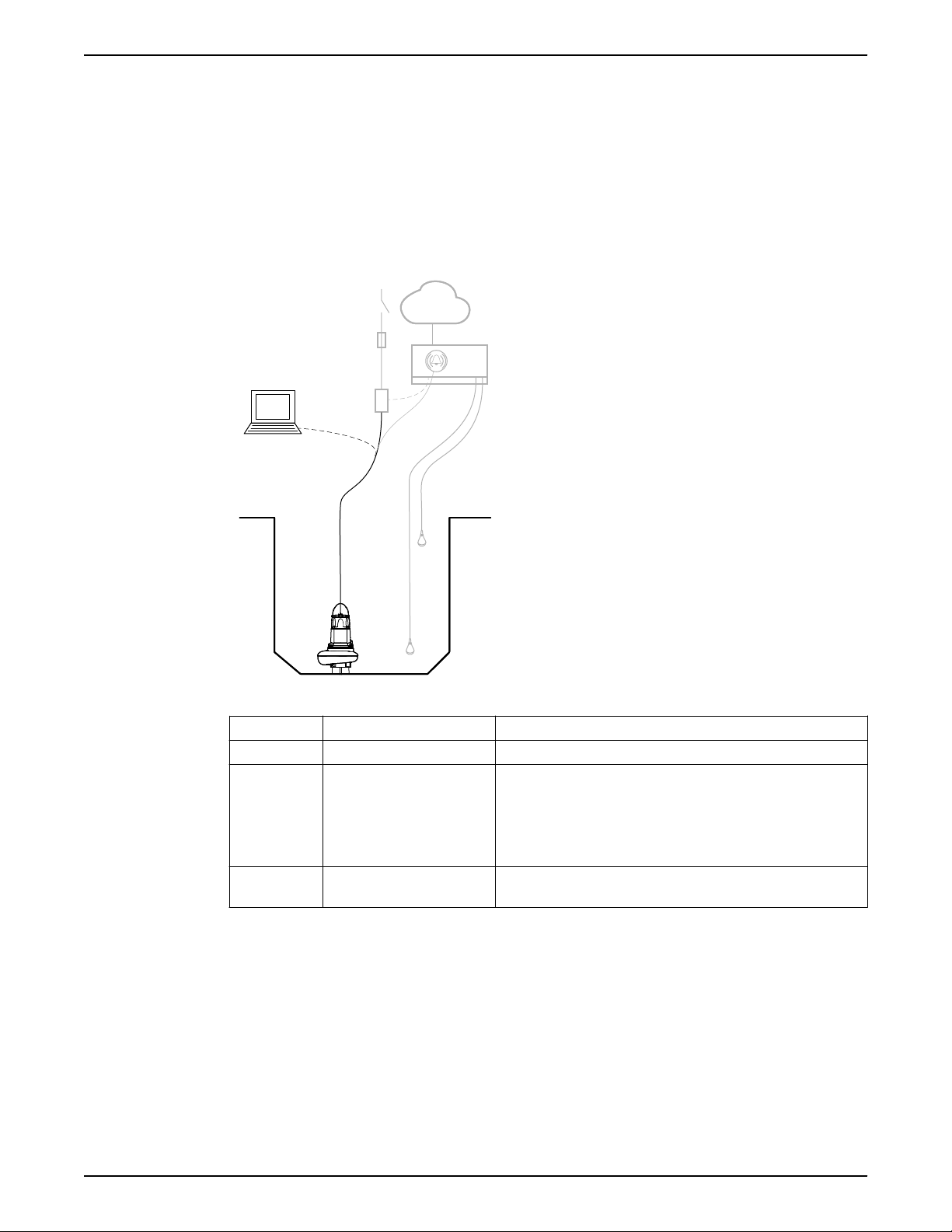
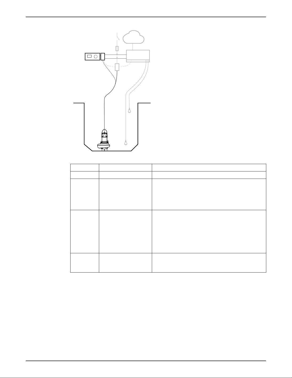
3.1 System overview
Concertor™ is a wastewater pumping system with integrated intelligent technology. The
system is available in different configurations depending on requirements in the pumping
applications.
3.1.1 Concertor™ N
3 System Description
Parts
Number Part Description
1 Pump A pump in the Concertor™ system series.
2 Components outside of the
Concertor™ system
3 PC application Dirigo™ Service Tool gives access to settings and log files.
Functions
• Pump clog detection
• Pump cleaning
• Soft-start
• Constant power
• Always correct rotation
• Pump sum-alarm I/O
• Change pump performance, Dirigo™ Service Tool
• Contactors, fuses, relays
• Control system
• Level sensors
• Cloud services
• Pump sum-alarm I/O
Connection is made through T3 and T4.
Concertor™ 6020 Installation, Operation, and Maintenance Manual 9
WS009753A
34
1
2
3 System Description
3.1.2 Concertor™ EA
Parts
Functions
Number Part Description
1 Pump A pump in the Concertor™ system series.
2 Components outside of the
Concertor™ system
• Contactors, fuses, relays
• Control system
• Level sensors
• Cloud services
• Pump sum-alarm I/O
3 Gateway, FPG 411 • The gateway starts and stops the pump based on the input
signal from the external control system.
– Digital input signal
– Modbus
• All the alarms are sent back to the external control system.
• The operator changes the pump settings through the gateway.
• Data is logged by and stored in the gateway.
4 HMI, FOP 312 The HMI is handheld, or mounted inside the cabinet or in the
cabinet door.
The HMI is optional.
• Pump clog detection
• Pump cleaning
• Soft-start
• Soft-stop
• Constant power
• Always correct rotation
• Set-up wizard
• Set pump performance (pump stopped)
• Pump alarms with priority A or B, I/O
• Pump and motor control alarms, HMI or Modbus
10 Concertor™ 6020 Installation, Operation, and Maintenance Manual
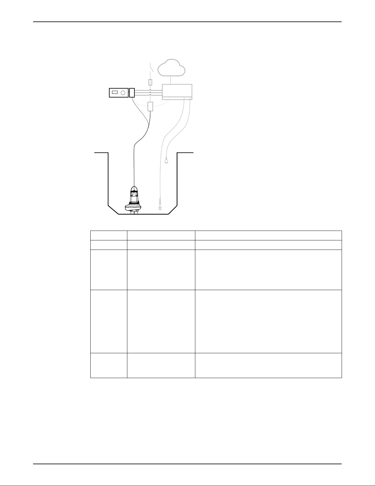
• Alarm handling
WS009754A
34
1
2
• Status and history
3.1.3 Concertor™ DP
3 System Description
Parts
Functions
Number Part Description
1 Pump A pump in the Concertor™ system series.
2 Components outside of the
Concertor™ system
• Contactors, fuses, relays
• Control system
• Level sensors
• Cloud services
• Pump sum-alarm I/O
3 Gateway, FPG 412 • The gateway starts and stops the pump based on the input
signal from the external control system.
– Digital input signal
– Analog input signal
– Modbus
• All the alarms are sent back to the external control system.
• The operator changes the pump settings through the gateway.
• Data is logged by and stored in the gateway.
4 HMI, FOP 312 The HMI is handheld, or mounted inside the cabinet or in the
cabinet door.
The HMI is optional.
• Pump clog detection
• Pump cleaning
• Soft-start
• Soft-stop
• Constant power
• Always correct rotation
• Set-up wizard
Concertor™ 6020 Installation, Operation, and Maintenance Manual 11

3 System Description
• External process control for dynamic pump performance, 4–20 mA or Modbus
• Pump alarms with priority A or B, I/O
• Pump and motor control alarms, HMI or Modbus
• Alarm handling
• Status and history
12 Concertor™ 6020 Installation, Operation, and Maintenance Manual

4 Product Description
Products included
System Pump version Gateway
Concertor™ N 6020.180 –
Concertor™ EA 6020.180 FPG 411
Concertor™ DP 6020.180 FPG 412
4.1 The pump
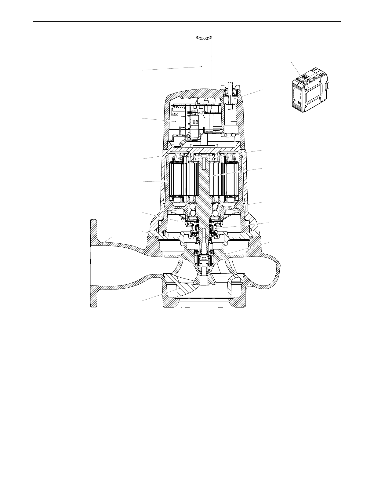
4.1.1 Pump design
The pump is designed for submersible use, and driven by a control system that is
connected to a permanent-magnet synchronous motor. For motor data, see Technical
Reference on page 48.
Intended use
The product is intended for moving waste water, sludge, raw and clean water. Always
follow the limits given in Technical Reference on page 48. If there is a question regarding
the intended use of the equipment, please contact a local sales and service representative
before proceeding.
4 Product Description
DANGER: Explosion/Fire Hazard
Special rules apply to installations in explosive or flammable atmospheres. Do not install
the product or any auxiliary equipment in an explosive zone unless it is rated explosionproof or intrinsically-safe. If the product is EN/ATEX-, MSHA- or FM-approved, then see
the specific EX information in the Safety chapter before taking any further actions.
Concertor™ 6020 Installation, Operation, and Maintenance Manual 13
WS009987A
8
10
11
12
13
9
5
4
3
15
2
1
6
7
RS485
DI
1
2
3
4
GND
A
AI
AO
HMI
1
2
3
4
5
B
GND
24VDC
+
_
+
_
+
_
PWR
DI1
DI2
DI3
DI4
DO1
DO2
DO3
DO4
ALARM A
ALARM B
PUMP RUN/CLEAN
PUMP COMMS
RS485
USB
NODE
ADDRESS
ON
OFF
MASTER
SLAVE
TERM
RS485
DO1
NO
COM
NO
GND
T4
T3
GND
DO2
DO1
NO
COM
NO
GND
DO2
ETHERNET
Concertor™
FPG411
1
2
3
4
5
6
7
8
9
0
14
4 Product Description
Illustrations
Figure 1: N 6020.180 MT/100, iron
14 Concertor™ 6020 Installation, Operation, and Maintenance Manual
WS009767A
8
10
11
12
13
9
5
4
3
15
2
1
6
7
RS485
DI
1
2
3
4
GND
A
AI
AO
HMI
1
2
3
4
5
B
GND
24VDC
+
_
+
_
+
_
PWR
DI1
DI2
DI3
DI4
DO1
DO2
DO3
DO4
ALARM A
ALARM B
PUMP RUN/CLEAN
PUMP COMMS
RS485
USB
NODE
ADDRESS
ON
OFF
MASTER
SLAVE
TERM
RS485
DO1
NO
COM
NO
GND
T4
T3
GND
DO2
DO1
NO
COM
NO
GND
DO2
ETHERNET
Concertor™
FPG411
1
2
3
4
5
6
7
8
9
0
14
4 Product Description
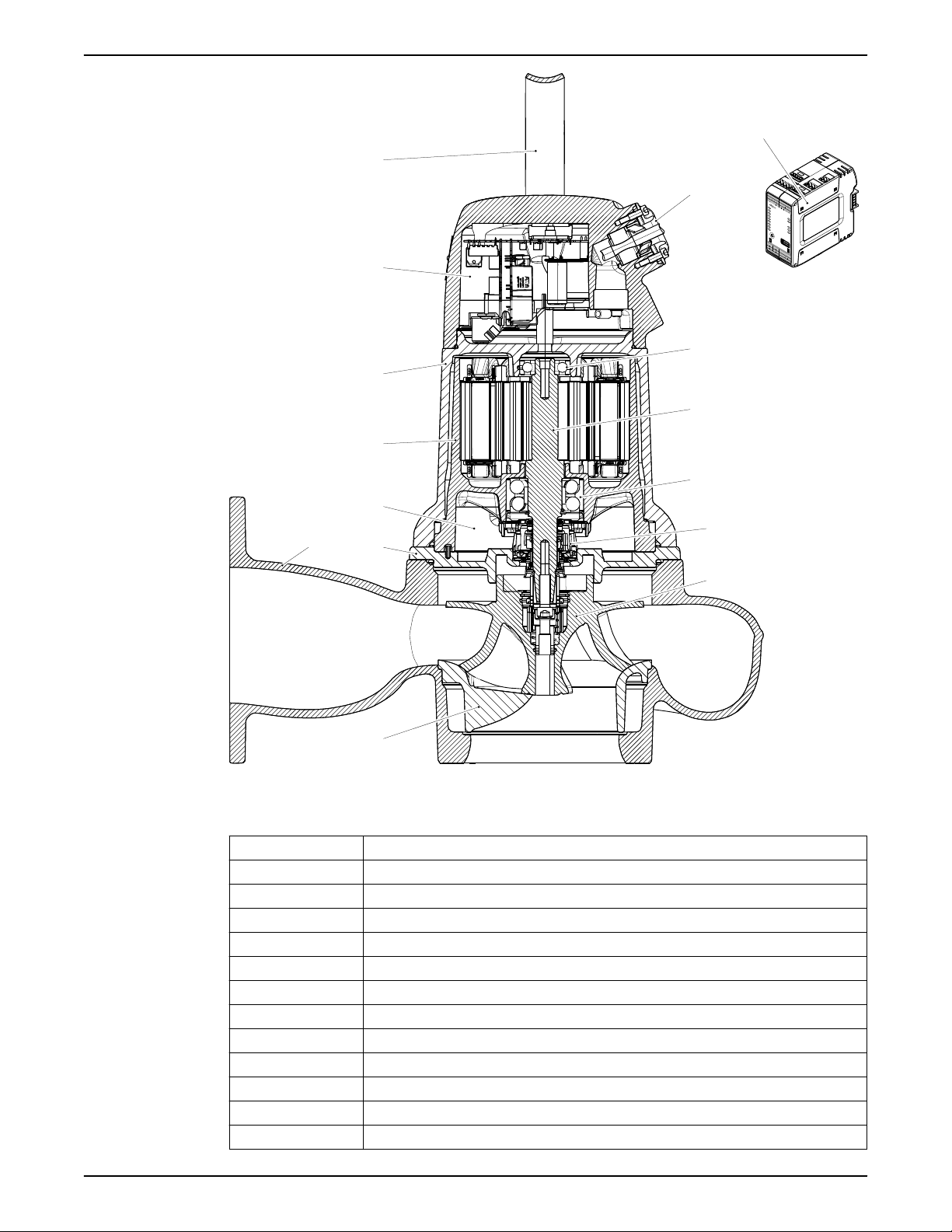
Parts
Figure 2: N 6020.180 LT/150, aluminum
Position Part
1 Insert ring with a guide pin
2 Pump housing, without flush valve connection
3 Seal housing cover
4 Stator housing unit with a leakage sensor
5 Cooling jacket
6 Connection housing with integrated control system
7 Lifting handle
8 Cable entry
9 Support bearing
10 Shaft unit with a permanent magnet rotor
11 Main bearing
12 Mechanical seal
Concertor™ 6020 Installation, Operation, and Maintenance Manual 15
 Loading...