

WolfVision VZ-P18, VZ-P38 Instruction Manual
Check out our Internet Homepage for additional information
www.wolfvision.com/support
VZ-P18 / VZ-P38
INSTRUCTIONS
BEDIENUNGSANLEITUNG
INSTRUCTIONS
BEDIENUNGSANLEITUNG
ENGLISH / DEUTSCH
VZ-P18 / VZ-P38
R

Table of Content
page
Precautions ...............................................................................................................................................1
Approval ....................................................................................................................................................2
Worldwide Patents ....................................................................................................................................2
Copyright Information................................................................................................................................2
Components of the Visualizer ...................................................................................................................3
Connectors...........................................................................................................................................4
How the Visualizer Works .........................................................................................................................4
Basic Preparations / Setting Up the Visualizer..........................................................................................5
Synchronized Lightfield........................................................................................................................5
Working Surface...................................................................................................................................5
Touch Panel ..............................................................................................................................................6
Synchronize Remote Control and Visualizer........................................................................................6
Remote Control / Battery......................................................................................................................6
Touch Panel Icons.....................................................................................................................................7
Available screens.................................................................................................................................7
On-screen Pointer..............................................................................................................................10
Infrared Remote control...........................................................................................................................11
Shooting Area On the Working Surface ..................................................................................................12
Shooting Area Outside of the Working Surface.......................................................................................12
Functions
Zoom / Digital Zoom...........................................................................................................................13
Focusing / One-Push Autofocus.........................................................................................................13
Auto Iris / Manual Iris .........................................................................................................................13
Preset Function..................................................................................................................................13
Freeze................................................................................................................................................13
White Balance Adjustment.................................................................................................................14
Text Mode...........................................................................................................................................14
Image Memory ...................................................................................................................................15
Snapshot .........................................................................................................................................15
View Mode.......................................................................................................................................15
Built-in Digital Scaler..........................................................................................................................16
Picture in Picture (PiP).......................................................................................................................16
Integrated Seamless Switch...............................................................................................................16
Image Turn Mode...............................................................................................................................16
Ports
USB Port to Computer .......................................................................................................................17
Ethernet / LAN Port............................................................................................................................17
DVI/RGB output .................................................................................................................................18
External Input.....................................................................................................................................19
RS-232, Serial Control Input ..............................................................................................................19
On-screen Menu .....................................................................................................................................20
Maintenance
Cleaning.............................................................................................................................................21
Firmware upgrades ............................................................................................................................21
Infrared codes ....................................................................................................................................22
Fuse ...................................................................................................................................................22
Dimensions .............................................................................................................................................23
Saving Visualizer Settings onto a USB-Stick ..........................................................................................25
Antitheft ...................................................................................................................................................25
External Lightboxes.................................................................................................................................25
Technical Data.........................................................................................................................................26
Precautions
ENGLISH
Please observe the following:
Risk of electric shock
Dangerous voltage inside
WARNING!
USE THIS VISUALIZER ONLY WITH THE CORRECT VOLTAGE AS SHOWN ON THE TYPE
LABEL !
DO NOT EXPOSE THE UNIT TO HEAT OR MOISTURE !
DO NOT CARRY THE VISUALIZER HOLDING IT ONLY BY IST MIRROR ARM !
DO NOT PUSH OR PULL THE ARM MANUALLY!
PROTECT THE UNIT FROM EXCESSIVE SHOCKS !
Make sure that sufficient air circulation for cooling the unit is possible (ventilation slots on
the underneath of the unit)!
If there is any abnormality (abnormal noise, smell, smoke etc.) disconnect the unit from
mains immediately and contact your Visualizer dealer!
Do not use a damaged power cord. This may cause short circuits or electrical shocks!
To prevent danger, do not modify the Visualizer or operate without the cover panel firmly in
place!
Do not expose the Visualizer to water, metallic objects or any flammable material.
Avoid installing the Visualizer in locations exposed to strong magnetic fields or electrical
currents.
Avoid installing the Visualizer in environments where there is radiation. This could cause
monitor image distortion or damage to the CCD camera.
Do not pull the plug from the power socket with wet hands!
If the Visualizer is not used for a long time, disconnect it from mains!
!
Remote control battery: Do not incinerate, disassemble, short terminals, expose to high
temperatures (above 140°F / 60°C)
1
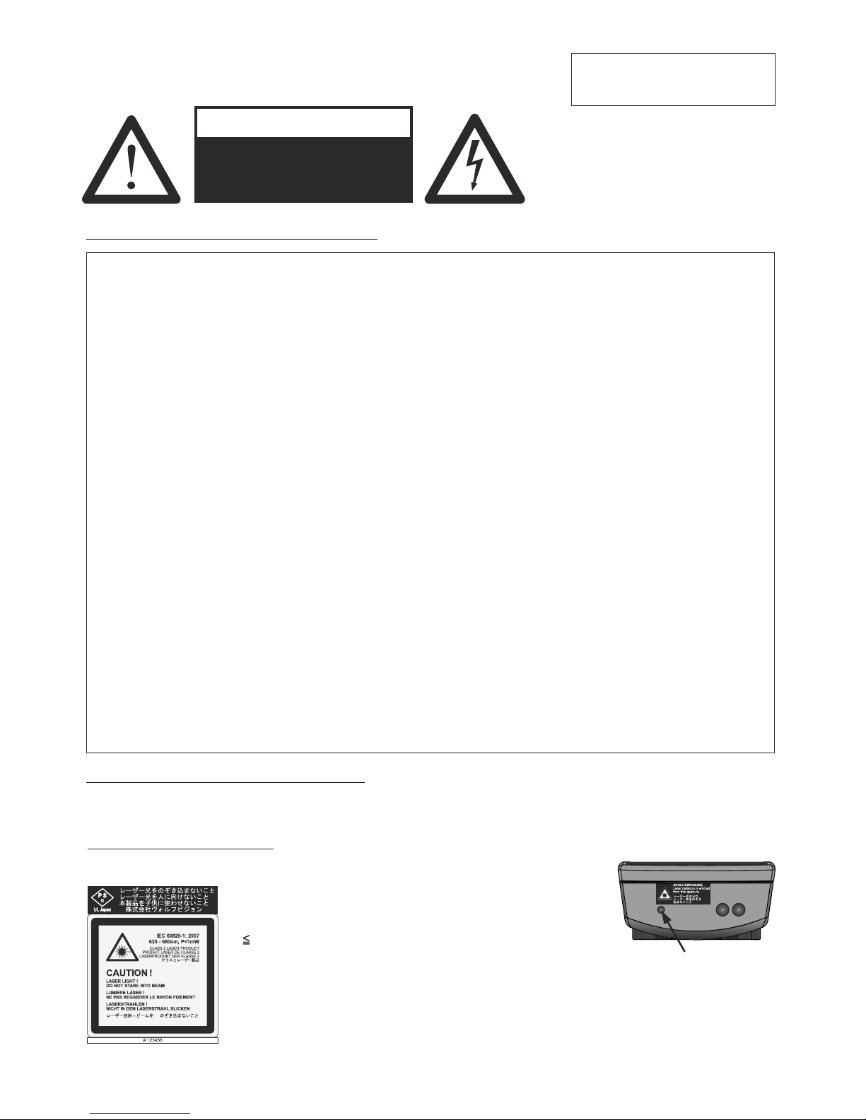
Precautions for laser pointer:
Laser light - Do not stare into beam!
Do not modify the laser! Do not view the laser beam with optical instruments!
Information for laser pointer
FDA accession number: 9912688-00
This device complies with 21 CFR 1040.10 and 1040.11
The laser beam exits the
remote control through the
smaller (left) opening on
the front.
Technical data:
λ = 635 - 680nm
P< 1mW
Θ 2mrad
This label will be found on the
underneath of the remote
control.

2
EU 0 362 737 KR 128059 AU 765617
DE P58907684.1-08 US 5,027,219 CN ZL99118847.0
CN 89107780.4 EU 0 987 874 and others
Jp1725033 JP 3 544 900
FCC information:
This device complies with part 15 of the FCC rules. Operation is subject to the following two conditions: (1)
this device may not cause harmful interference, and (2) this device must accept any interference received,
including interference that may cause undesired operation.
Note:
This equipment has been tested and found to comply with the limits for a class B digital device, pursuant to
part 15 of the FCC rules.
Information to user:
The user manual or instruction manual for an intentional or unintentional radiator shall caution the user that
changes or modifications not expressly approved by the party responsible for compliance could void the
user's authority to operate the equipment.
This product is built according to Directive EMC and to Directive electrical equipment.
Inspections, tests and evaluation are according to UL 60950. CSA 22.22-60950
Inspections, tests and evaluation are according to the CB-Scheme
Inspections, tests and evaluation are according to the PCT-Scheme
Marks on the unit:
Approval
Worldwide Patents
Copyright Information
Copyright © by WolfVision. All rights reserved.
WolfVision, Wofu Vision and are registered trademarks of WolfVision Holding AG, Austria.
No part of this document may be copied, reproduced, or transmitted by any means, without prior written
permission from WolfVision. Except documentation kept by the purchaser for backup purposes.
In the interest of continuing product improvement, WolfVision reserves the right to change product
specifications without notice.
Information in this document may change without notice.
Disclaimer: WolfVision shall not be liable for technical or editorial errors or omissions.
The units are "MADE IN EU/AUSTRIA”
Printed in Austria, November 2013
US
C
L
I
S
T
E
D
9902476
Tested to complywith
FCC standards for
home or office use
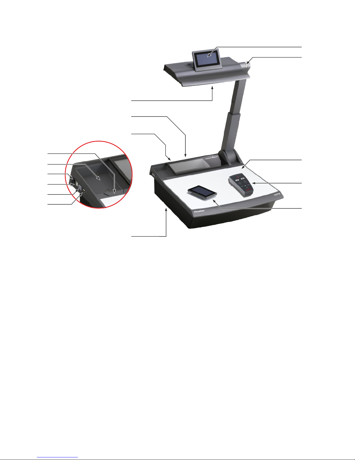
Components of the Visualizer
#1
#8
#10
#1 Remote Anti-theft Security Screw to fix the Remote control onto the case
(found underneath the unit as shown on page 25)
#2
#3 POWER key and Power Indication LED(see page 5)
#4 USB port to Host (computer) (see page 15)
#5 DC-output for lightbox (see page 25)
#6 Charging Dock for Touch Remote Control (see page 6)
#7 Touch Remote Release button press and lift the Touch Remote Control
#8 Connectors (on the back as shown on next page)
#9 Infrared receiver (one ir receiver on the back and on behind the glass)
#10 Sensing Head Mirror (sensitive front coated mirror)
#11 Touch Head (Panel) on the sensing head (see pages 6ff)
#12 Zoom wheel (see page 13)
#13 Working surface (see page 5)
#14 Infrared Remote Control (see pages 11 and 22)
#15 Touch Remote Control (radio frequency) (see pages 6ff)
USB port to Client (peripheral devices for external storage units) (see page 17)
3
#4
#3
#6
#5
#2
#7
#15
#9
#14
#13
#11
#12
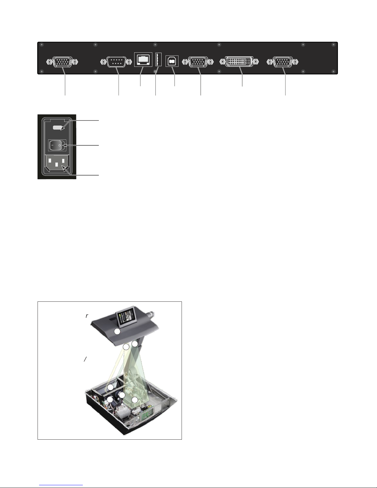
#16 RGB output (15pin) (see pages 18, 19)
#17 RS-232 serial control input RS232 (see page 17)
#18 LAN port (see page 17)
#19
#20 USB port to Host (computer) (see page 15)
#21 Preview RGB output (15pin) (see pages 18, 19)
#22 DVI-I output (see page 18)
#23 (see page 19)
#24 Fuses F1.5A (see page 22)
#25 Main Power Switch
#26
10/100 TBase
USB port to Client (peripheral devices for external storage units) (see page 17)
External Input for Computer RGB-signals (15pin)
Power connection Mains Socket
#23
#20
#22
#18
#17
#19
#21#16
LAN
DVI
PREVIEW
USB
EXTERN
RS-232
RGB
Connectors (#8)
FUSE
T3,15A
#25
#24
#26
How the Visualizer Works
1) light projector
2) camera
3) light path
4) image path
5) base mirror
6) top mirror
7) pickup area /
synchronized
lightfield
A light projector inside the unit projects a light
field ‡ the same size as the pick-up area of the
built-in camera via the base mirror … and the top
mirror † onto the working surface. The image is
recorded by the camera ‚ using the same path.
The lenses of the light projector and the camera
‚ are synchronized. Thus the size of the light field
on the working surface changes when the user
changes the zoom range of the camera.
This patented WolfVision scanning and
illuminating system offers a number of unique
advantages.
6
1
2
3
4
5
7
4

Basic Preparations / Setting Up the Visualizer
1. Connect the power cable to the unit (#26) and plug it in.
2. Connect your display device (projector, monitor, video conferencing unit
etc.) to the appropriate output of the Visualiz
If you would like to use a control monitor, connect it to
the PREVIEW RGB output (#21).
3. Turn the main power switch (#25, on the back of the unit) to "I". The
power indication LED (#3) is illuminated white to indicate that power is
supplied (takes about 40 seconds).
4. Press the POWER key (#3) to switch on the Visualizer. If folded down,
the arm will automatically rise into the correct working position.
The Visualizer now runs the "power-on preset"
5. When using the Visualizer the first time, please insert the battery into the
remote control and charge it in the charging dock (#6).
6. To fold the arm down, keep the POWER key (#3) pressed until the arm
starts moving.
Power-on preset:
The automatic setting of zooming to an DIN A5 format (approx. 20 x 15 cm),
focus on the working surface level, the auto iris activated and touch display
on the sensing head is up. As soon as the Power Indication LED (#3) stays
green, you can start working with the Visualizer. The behavior of the unit
once the power has been supplied or after the POWER key has been
pressed can be changed in the unit's on-screen menu.
Please note, when the unit is switched on for the first time, the Quick Setup
Guide will be started automatically. Please set all necessary settings. The
settings can be changed later in the on-screen menu (see page 20).
er (#16, #21 and/or #22).
IMPORTANT:
For choosing the right output please read the detailed
description on page 18!
The synchronized light field makes positioning of objects very easy by marking the pick-up area of the builtin camera on the working surface. The light field zooms synchronous to the camera zoom and shows the
4:3 or 16:10 pick-up size of the camera.
Additionally the built-in LCD monitor eliminates the need for an extra control monitor.
This monitor can also be used to control the Visualizer (e.g. to synchronize the remote control).
The alignment of this lightfield is made for working on the working surface. Due to the oblique mounting of
the camera and the light projector of the Visualizer, the lightfield shifts to the left when the distance between
the Visualizer and the scanned object is increased (when capturing images outside of the working surface).
This means that the lightfield will no longer show the exact recorded area. In this case switch off the
Visualizer’s top light with the LIGHT icon and work with ambient light.
Synchronized Lightfield
Working Surface / Lightbox (optional)
The working surface of the Visualizer (#13) has a special crystalline white color, which is especially
designed for perfect reproduction of transparencies.
It is recommended to use the top light for transparencies due to better color reproduction.
In the following cases, an optional light box is recommended:
- If the transparency is very dark such as x-rays
- If the transparency is very wavy and causes reflections
- If ambient light causes reflections on transparencies
Using the light box has the disadvantage that the synchronized lightfield of the top light no longer marks the
pick-up area of the built-in camera.
5
F

Synchronize the remote control with the Visualizer unit. For proper operation, the touch remote
control must be synchronized. Open the Tolbox screen and tap the SYNCHRONIZATION icon on
the mirror head control panel and on the remote control panel. A message will appear on both
screens that synchronization is in progress. A message will appear on the mirror head control
panel indicating that synchronization is complete. (Synchronization is necessary e.g. when using
a new touch remote control.)
Synchronize Touch Remote Control and Vizualizer
Control Panel Screen (touch panel)
Advanced User Mode (default)
Home: Preset 1, Freeze, Extern, View, , Power and Zoom Slider
Advanced Functions: AutoFocus (AF), Zoom, Mirror, Iris and Focus as Slider
Options: Memory 1-9 / View Mode / Menu Navigation (screen changes in accordance to
the selected operating mode)
Magic Wand: Preset 1 - Preset 3, Snapshot, Extern, Image Turn, PiP, Menu and Light
Toolbox: User Mode, backlight illumination (remote only) and Synchronize Remote
(keep the Home icon pressed for four seconds to activate the Toolbox screen)
Basic User Mode
AutoFocus (AF)
WhiteBalance,
Home: AutoFocus (AF), Power and Zoom Slider
View: Memory 1-9
Toolbox: User Mode, backlight illumination (remote only) and Synchronize Remote
(keep the Home icon pressed for four seconds to activate the Toolbox screen)
Service User Mode
Home: Preset 1 - Preset 3, View, Menu, Power and Zoom Slider
Advanced Functions: AutoFocus (AF), Zoom, Mirror, Iris and Focus as Slider
Options: Memory 1-9 / View Mode / Menu Navigation (screen changes in accordance to
the selected operating mode)
Magic Wand: Preset 1 - Preset 3, Snapshot, WhiteBalance, Extern, Image Turn, PiP and Light
Toolbox: User Mode, backlight illumination (remote only) and Synchronize Remote
(keep the Home icon pressed for four seconds to activate the Toolbox screen)
The Touch Remote Control is equipped with a lithium polymer rechargeable battery.
Before you use the remote control the first time, please insert the battery and charge it for three hours.
To recharge the battery, place the remote control in the Visualizer's charging dock. The Visualizer
has to be powered on (at least standby mode).
The rechargeable battery should only be replaced with the identical type:
103267 Battery for remote control, VZ-P18/P38
Do not incinerate, disassemble, short circuit or expose to high temperature (above 140°F / 60°C).
The battery symbol on the remote control displays the SOC, State of Charge (green=full, red=empty). As
soon as the battery is nearly empty, an appropriate on-screen message will be shown on the remote
control.
To switch on the remote control, just press the power key on
it (top short side) or place it in the charging dock.
Touch Remote Control / Battery
One of the outstanding features of WolfVision's Professional Visualizers is that only the most important
icons are visible. Therefore anyone can use it without instructions.
To power on the remote place it into the charging dock or press the power key on top of the remote control.
The remote control vibrates after each tap and after switching it on.
For more experienced users, additional functions on further control panel screens can be activated. The
individual control panel screens unite related features. The availability of the additional control panel
screens and icons are dependent on the selected User Mode.
The antenna symbol on the remote control displays the reception quality. In the case that the antenna
symbol is red, check your location, the operating status of the Visualizer or synchronize the remote control.
Please note, the available symbols and functions can vary with different firmware versions.
6
Control Panel Screens
The Menu Bar icons are found along on the top edge of the screen on the remote control (they are
along the left edge of the screen on the Touch Head Screen). Tapping on the desired Menu Bar icon to
change the shown screen.
On the following pages, the screens of the Advanced User Mode are shown. The functions marked with
* are not available in Basic User Mode.
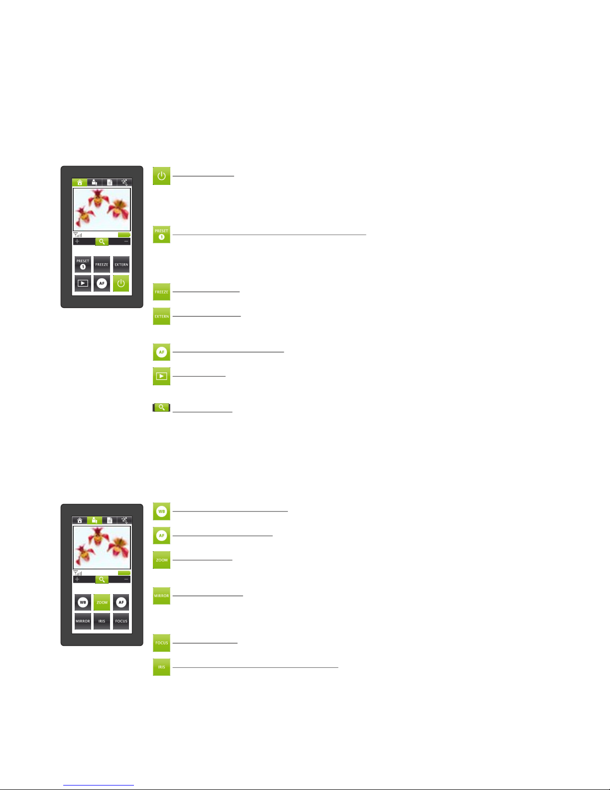
HOME Screen - the most commonly-used functions
Navigate to this screen by tapping the HOME icon in the menu bar.
POWER icon (Remote control only, physical key on the left side of the Visualizer)
Toggle between full power and stand-by mode. It is highlighted when in full power
mode. If the unit is in Deep-Power-Down mode (special power saving mode,
selectable in the on-screen menu) use the power key on the left side of the Visualizer
(see page 20).
*PRESET icons (programmable settings)
To recall a preset configuration setting, tap the PRESET icon quickly.
To capture the current configuration and save it as a preset, press and hold the
PRESET icon for at least 2 seconds.
In Service User Mode, preset 1 to 3 are available (instead of FREEZE and EXTERN).
*FREEZE icon
Freezes the current live image. Tap again to display the live image (see page 13).
*EXTERN icon
Toggle between the signals sent to the output ports: either the live camera image or
the signal from the External Input port.
AUTO FOCUS (AF) icon
Perform the one-push Auto Focus function (see page 13).
*VIEW icon
Enter the VIEW mode and the control panel switches to the VIEW screen (see page
15).
ZOOM slider
Tap the magnifying glass and drag it toward + to zoom in, and toward - to zoom out.
The closer the icon is to the middle, the slower the zoom motor operates.
Using the ZOOM sliders also switches the auto iris on again.
*ADVANCED FUNCTIONS screen - special image-adjustment functions
Navigate to this screen by tapping the ADVANCED FUNCTION icon in the menu bar.
The closer the icon is to the middle, the slower the respective motor operates.
WB(White Balance) icon
Perform the one-push White Balance function (see page 14).
AF (Auto Focus) icon
Perform the one-push Auto Focus function (see page 13).
ZOOM slider
Tap the magnifying glass and drag it toward + to zoom in, and toward - to zoom out.
Using the ZOOM sliders also switches the auto iris on again.
MIRROR slider
Tap the MIRROR icon and drag it toward + to move the mirror toward the top of the
working surface, and toward - to move the mirror toward the bottom of the working
surface. The mirror can also be adjusted by hand.
FOCUS slider
Tap the FOCUS icon and drag it toward + to focus manually (see page 13).
IRIS slider (brightness adjustment)
Tap the IRIS icon and drag it toward + to open the iris and brighten the image, or
toward - to close the iris and darken the image. When the iris is adjusted manually, the
Auto-Iris setting is automatically disabled. The next time the ZOOM function is used
the Auto-Iris setting is re-enabled (see page 13).
7
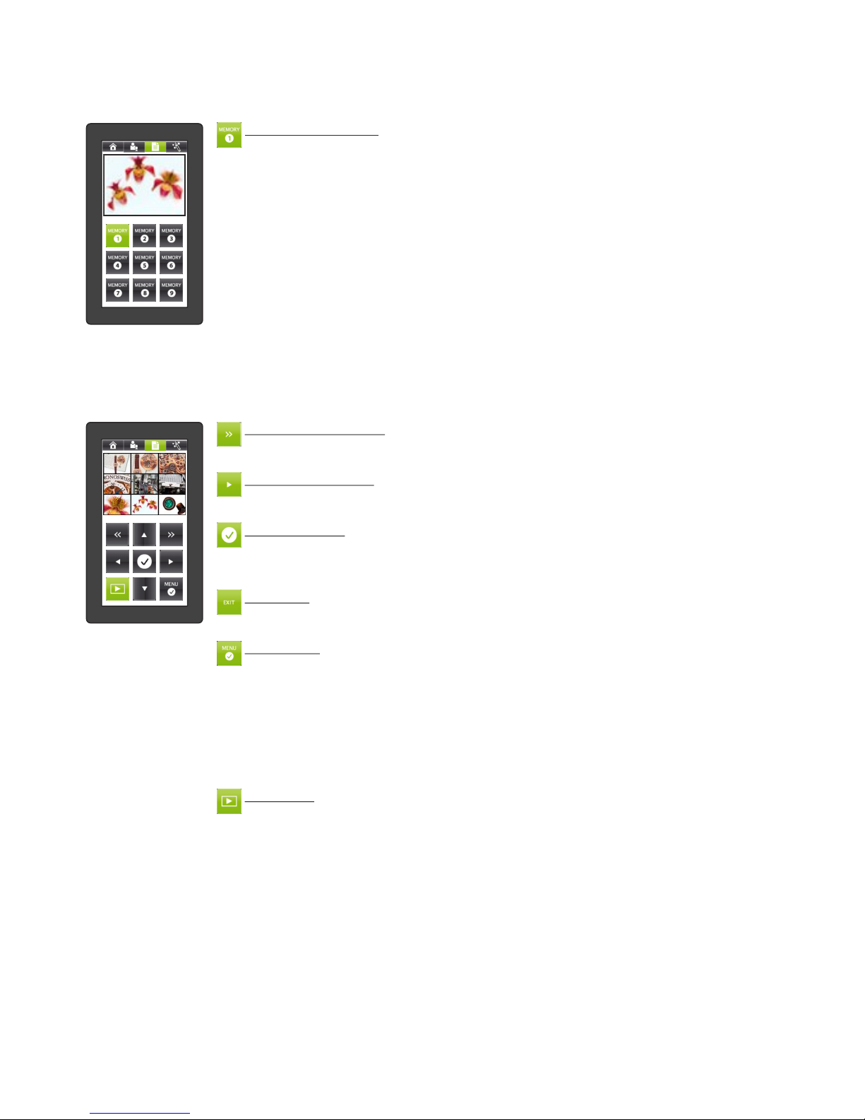
MEMORY screen - store and recall up to 9 images to/from internal memory
Navigate to this screen by tapping the Options screen in the menu bar (not available when the VIEW mode or
the MENU mode is activated)
MEMORY icons 1 - 9
Press and hold on of the MEMORY icons for at least 2 seconds to save the current live
image in the corresponding memory slot. An on-screen message will appear to
indicate that the image was saved.
Tap the MEMORY icon to recall and display its previously-saved image (see page 15).
Once a saved image is displayed, you may go to either the HOME or ADVANCED
FUNCTIONS screens (or use the ZOOM wheel on the mirror arm) to zoom in on the
image digitally. When you zoom in on a saved image, the control panel will change to
the ZOOM MODE screen and its screen will change.
*VIEW screen - manage image memory (internal and external) and starting the presentation mode
Navigate to his screen by tapping the VIEW icon in the control bar.
The VIEW screen shows a split screen with 3x3 pictures. The currently-selected image is framed with a colored
border: red for images in internal memory and blue for the images on the USB storage device.
8
PAGE SELECT icons
Move to the next or previous page of 9 images.
The page functions will only operate with a present USB storage device.
NAVIGATION icons
Move the selection frame to one of the images on the current page by using the four
arrow icons.
CONFIRM icon
Display the selected image in full size. This causes a change of the currently available
icons to image forward/backward and confirm. Tap the confirm icon to return to the
3x3 initial display.
EXIT icon
Use the EXIT icon to stop the memory zoom mode.
The EXIT icon is available as soon as zoomed-in on the recalled memory.
MENU icon
Tap the MENU icon to open the on-screen VIEW menu. In this on-screen menu, you
can change the folder on the USB-stick (temporarily), copy and delete pictures, start
the Presentation Mode and format the USB storage device.
Please note, when you format the USB stick, all data will be lost!
With the Presentation Mode (Slideshow), you can show all pictures in the currently
selected folder automatically with a pre-defined interval. To switch to the Live image,
just tap the VIEW icon; tap it again to proceed the Presentation Mode. To finish the
Presentation Mode, tap the EXIT icon.
VIEW icon
Tap this icon to toggle between internal memory, external memory (USB storage
device and Live image.
As soon as the Presentation Mode is running, tapping the VIEW icon switches
temporarily to the live image without aborting the presentation.
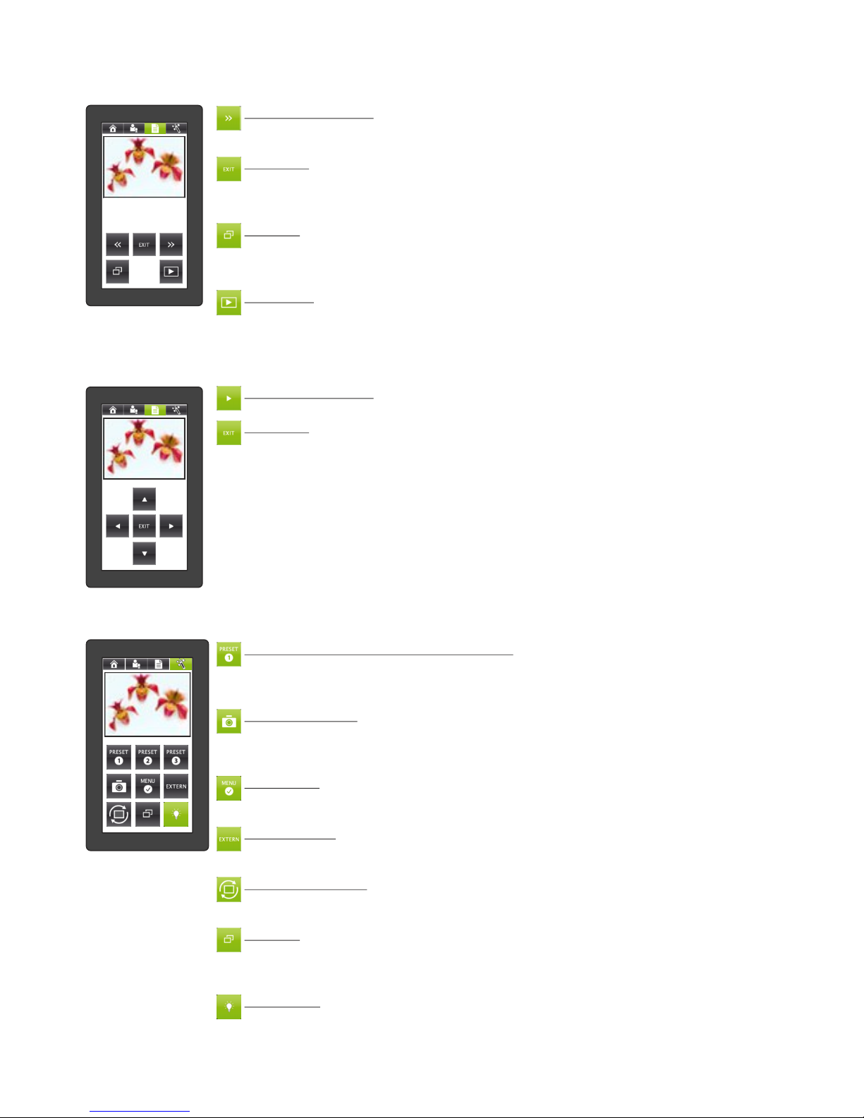
*PRESENTATION screen - manage an on-going Presentation (slideshow)
Navigate to this screen by starting a Presentation from the Visualizer‘s on-screen menu in the View mode.
*MAGIC WAND screen - special functions
Navigate to this screen by tapping the MAGIC WAND icon in the menu bar.
PRESET icons (programmable settings)
To recall a preset configuration setting, tap the PRESET icon quickly.
To capture the current configuration and save it as a preset, press and hold the
PRESET icon for at least 2 seconds.
SNAPSHOT icon
Store a JPG snapshot of the live camera image in a file in the current USB folder,
when a USB-storage device is present, or in the next available internal memory slot
when no USB-device is present.
MENU icon
Open the on-screen menu of the Visualizer. The control panel will show the menu
screen.
EXTERN icon
Toggle between the signals sent to the output ports: either the live camera image or
the signal from the External Input port.
IMAGE TURN icon
Rotate the orientation of the output image by 90°. Each tap of the icon rotates the
image another 90°.
PiP icon
Display the current image in a small PiP box at the lower left while displaying the live
camera image in a larger box at the upper right. Tapping the PiP icon again toggles
back and the Visualizer displays the previous image (see page 16).
LIGHT icon
Toggle on and off the synchronized light field on the working surface. If an optional
lightbox is connected to the Visualizer, the icon is a three-way toggle between
synchronized light field, light box and no light.
MEMORY ZOOM MODE screen - pan around a zoomed image retrieved from memory
Navigate to this screen by performing a zoom operation on a recalled image from internal or USB memory (or
tapping the options icon when memory zoom mode is active).
NAVIGATION icons
Pan around the zoomed image using the four arrow icons.
EXIT icon
Exit the zoomed display of a saved image. The non-zoomed version of the image will
be re-displayed and the ZOOM MODE screen will be exit and the previous screen will
be displayed.
9
NAVIGATION icons
Move to the next or previous „slide” image.
These icons have no function in automatic slide show mode.
EXIT icon
End the current slide show. An on-screen menu appears to confirm the exiting of the
slides show. The screen switches to the menu screen to allow a response to the onscreen menu.
PiP icon
Display the current image in a small PiP box at the lower left while displaying the live
camera image in a larger box at the upper right. Tapping the PiP icon again toggles
back and the Visualizer displays the previous image (see page 16).
VIEW icon
Toggle between viewing the current slide show image and the live camera image.
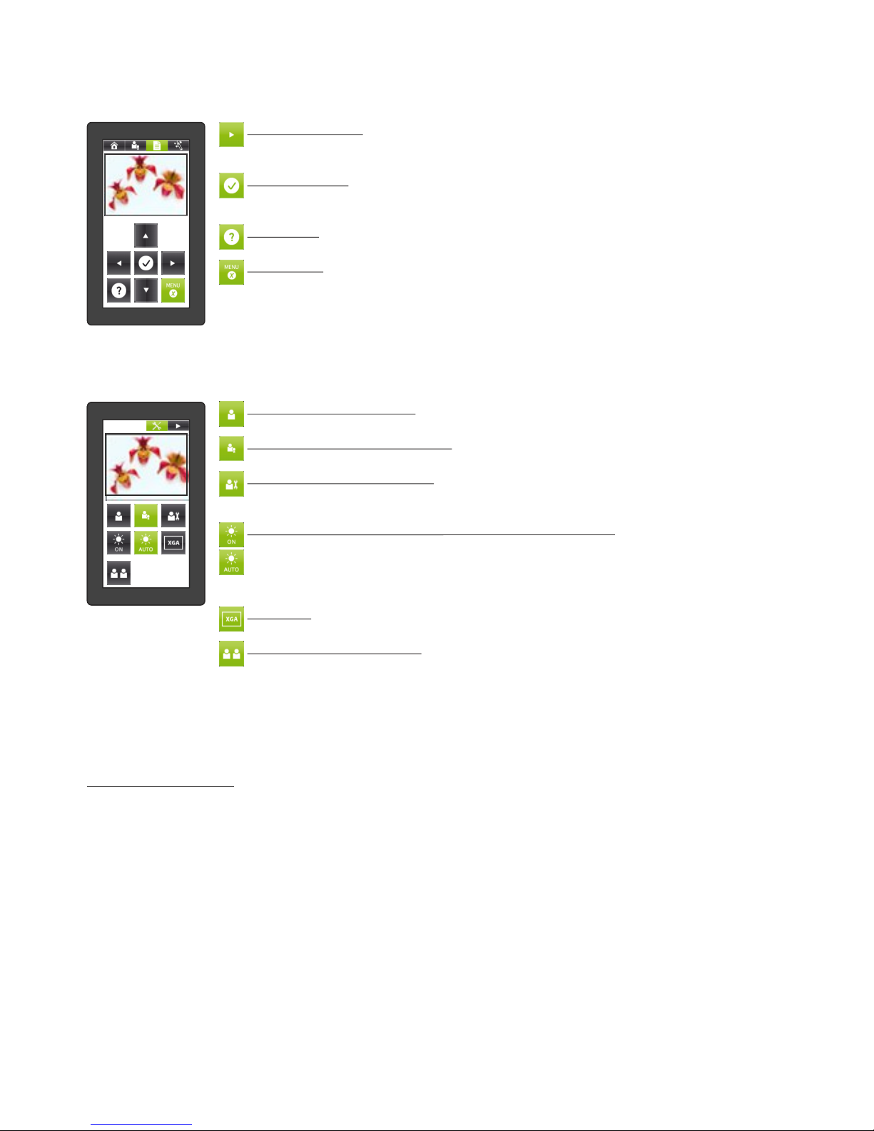
*MENU screen - navigate the Visualizer‘s on-screen menu
Navigate to this screen by going to the MAGIC WAND screen, then tapping the MENU icon (in some modes,
like VIEW mode, the on-screen menu can be entered from there screen.
Navigation icons
Use the up/down arrows to move to and highlight a specific item in the on-screen
menu. Use the left/right arrows to change settings.
CONFIRM icon
Select the currently-highlighted item in the on-screen menu and either perform its
action or enter its sub-menu.
HELP icon
Display help text about the currently highlighted item in the on-screen menu.
MENU icon
Exit the on-screen menu mode. The control panel returns to the screen from which
the on-screen menu screen was initiated.
TOOL BOX screen - special configuration functions
Navigate to this screen by pressing and holding the HOME icon in the menu bar until the TOOL BOX appears.
Exit the TOOL BOX by tapping the arrow icon at the corner.
BASIC USER MODE icon
Enable only the most basic functions in the control panel screen.
ADVANCED USER MODE icon
Enable all screens and functions in the control panel.
SERVICE USER MODE icon
Enable all screens and functions in the control panel, and move certain functions to
different screens.
BACK LIGHT ON / AUTO icon (touch remote control only)
Manage the control panel backlight power-saving feature. When the ON icon is
tapped and highlighted, the backlight will stay on continuously. When the AUTO icon
is tapped and highlighted, the backlight will be switched off after a certain amount of
time of inactivity.
XGA icon
Set the resolution on all outputs to XGA resolution (1024x768 pixels at 60Hz).
SYNCHRONIZATION icon (necessary when using a new remote control)
Synchronize the remote control with the Visualizer unit. For proper operation, the
remote control must be synchronized. Tap the SYNCHRONIZATION icon on the
mirror head control panel and on the remote control panel. A message will appear on
both screens that synchronization is in progress. A message will appear on the mirror
head control panel indicating that synchronization is complete.
On-Screen Pointer
On the side of the remote control, you will find the POINTER keys. By pressing one of the POINTER keys, a
digital pointer will be displayed on the screen. To move the pointer, just tilt the remote control whilst pressing
the key.
10
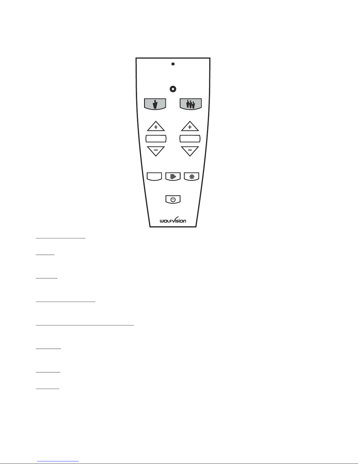
Infrared Remote Control
The IR remote control offers a comfortable and very easy way to control basic functions of the
Visualizer.
LASER POINTER
Important: Do not stare directly into the laser beam. This is hazardous for your eyes!
ZOOM
Press TELE to zoom in or WIDE to zoom out.
Using the ZOOM keys also switches the auto iris on again.
FOCUS
Press the FOCUS key to perform the one-push Auto Focus function or focus manually by using the +/- keys
(see page 13).
SCROLL (top mirror)
Press the SCROLL key to centre the pick-up area to the working surface. To scroll, please use the +/- keys.
The mirror can also be adjusted by hand.
PRESET (programmable settings)
To recall a preset configuration setting, press the PRESET key quickly.
To capture the current configuration and save it as a preset, press and hold the key for at least 2 seconds.
EXTERN
Toggle between the signals sent to the output ports: either the live camera image or the signal from the
External Input port.
FREEZE
Freezes the current live image. Press again to display the live image (see page 13).
POWER
Toggle between full power and stand-by mode. (see page 20).
11
LASER
EXTERN FREEZE
FOCUS
PRESET
TELE
WIDE
1
SCROLL
POWER
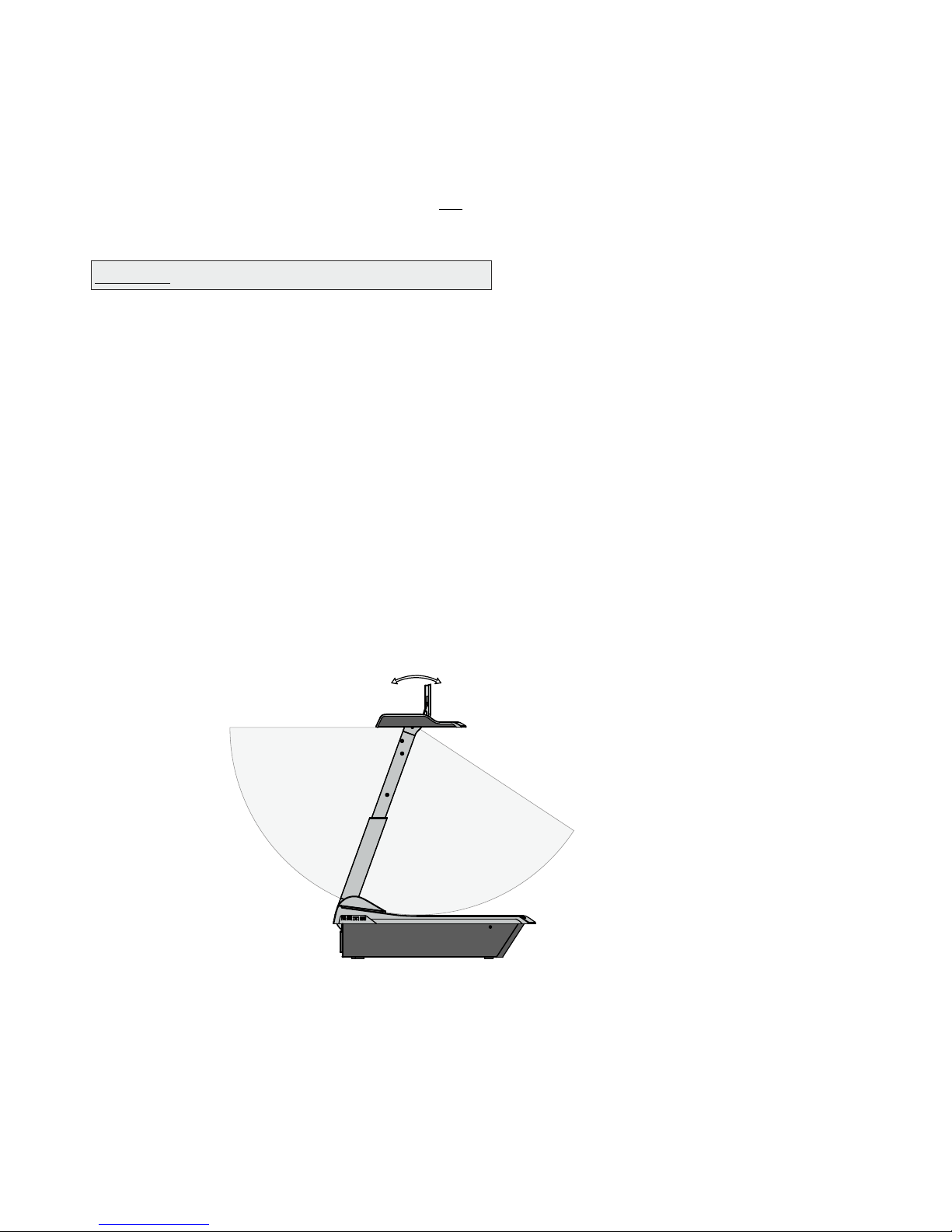
To show 3-dimensional objects with the WolfVision Visualizer, just place them on the working surface and
adjust ZOOM and FOCUS. Due to a special WolfVision lens the object can be up to 25 cm (9.7") in height. If
the object is too big for the working surface or if you want to show it from the side, just place it behind or in
front of the unit and tilt the top mirror by hand or by using the MIRROR slider.
In this way it is also possible to make recordings of objects in the room or surrounding area, just like with a
video camera.
Due to the Visualizer's great focal range it is possible to show details from any distance to the unit.
If you want to record people you should turn off the light with the LIGHT icon, so that they are not blinded by
the light.
Shooting Area Outside of the Working Surface
1. Place your subject material on the working surface. The synchronized lightfield on the working
surface marks the pick-up area of the built-in camera. Just place your subject material in the illuminated
area.
2. Select the enlargement required with the ZOOM slider (wheel).
3. Use the MIRROR slider to change the vertical position of the pick-up area. The sensing head (top
mirror) can also be moved by hand. This does not cause any harm to the mirror‘s motor.
Do not touch the mirror surface, as fingerprints cause bright and hazy spots on the picture! Always keep the
mirror clean! - see page 21
CAUTION: SENSITIVE FRONT COATED MIRROR!
Shooting Area on the working surface
Eliminating reflections
In order to eliminate reflections (on high gloss photographs etc.) just move the document and rotate the
sensing head to the center of the desired pick-up area.
Please note that reflections can also be caused by general room lighting conditions.
12
to infinity
Tilt range:
105° (30° to speaker + 75° to audience)

When the Visualizer is turned on the focus automatically adjusts to the working surface level (power-on
preset). As a result it is not necessary to readjust the focus if you are only working with flat materials (text,
photos etc.).
Due to the extreme depth in focus of the Visualizer, the focus rarely needs to be adjusted.
Only very high objects require a focus adjustment.
To activate the One-Push Auto focus, tap the AF icon.
Please note that objects with very low contrast (like blank paper) are difficult to focus.
Focussing / One-Push Autofocus
WolfVision Visualizers are equipped with an auto iris. This means that the brightness of the camera image
adjusts automatically. When using the IRIS slider the auto iris function is switched off. In this mode the Iris
can be adjusted manually.
When using the ZOOM slider/wheel the auto iris function is switched on again.
The standard auto iris level can be set brighter or darker in the unit's on-screen menu. When picking up
areas with bright spots, Back Light Compensation can be switched on in the unit‘s on-screen menu - see
page 20 and on-screen help.
Auto Iris / Manual Iris
The Visualizer offers the possibility to store the current settings as a Preset and recall them by just tapping
the respective PRESET icon.
To store a reset adjust y function as required and then PRESET icons for 2 seconds
. An on-screen messageinform you when the reset is stored.
As mentioned above, when presets are stored all current settings such as zoom, focus, iris etc. are also
stored. Contrary to this, a user also has the opportunity to assign only specific functions such as
"NEGATIVE", "NEGATIVE/BLUE", "BLACK/WHITE" etc. to a PRESET icon in the on-screen menu of the
Visualizer (see page 20).
p : an tap any one of the
or more s p
You can select if the mirror position should be stored in a preset or not in the unit's on-screen menu (see
page 20). Default is: YES
Preset Function
Freeze / Live to Freeze Comparison (two display devices)
The current image can be captured by tapping the FREEZE icon. The FREEZE icon is illuminated green
when the freeze function is activated.
The DVI- and RGB outputs of the Visualizer can be set to output different signals. This can be used for a
"Live Picture to Freeze Picture Comparison" on two monitors or screens with just one Visualizer.
While one monitor or screen displays a "freeze" image that can be used for comparison, another monitor or
screen can be used for presenting the live image from the Visualizer.
The settings of the FREEZE function can be changed in the on-screen menu (see page 20).
Please note that the Visualizer has an optical 16x zoom. For zooming use the ZOOM slider / wheel .
The digital 4x zoom increases the overall zoom range to a 64x zoom. The smallest pickup size on the
working surface without digital zoom is 33 x 25mm (1.3" x 1"). When you zoom in further the digital zoom is
automatically activated and the smallest pickup size is 8 x 6mm (0.3" x 0.25"). However, please be aware
that when the digital zoom is used, the resolution of the picture is not as good as before. The default setting
displays a message on-screen when you are in the digital zoom mode. Still pictures in the memory can also
be digitally zoomed.
You can change Visualizer‘s digital zoom mode settings in the on-screen menu (see page 20).
(#12)
Turn the wheel down to zoom in (TELE), and up to zoom out (WIDE). The more you turn the ZOOM wheel,
the faster the zooming works. Using the ZOOM function also switches the auto iris on again.
Zoom / Digital Zoom
13

Correct white balance adjustment is important for an exact color reproduction!
This means that the white balance
is continuously adjusted automatically.
For an exact white balance, at least 10% of the recorded image should be white.
For a precise fixed white balance adjustment use the "One Push" white balance. This can be done by
tapping the WB icon. When the white balance is stored an on-screen message appears. Setting a "One
Push" white balance switches off the "Auto Tracking" mode (when the unit is switched off and on again the
"Auto Tracking" mode will be reactivated).
For specialists: The Visualizer can be switched between "Auto Tracking", "One Push" and "Manual"
white balance mode in the on-screen menu (see page 20). If you work with negative transparencies and a
light box, use a blank (black in the image) part of the negative film for white balance adjustment! The "one
Push" white balance will be separately adjusted and stored for top light and external light box.
Each time the lighting condition changes, the Visualizer's camera must readjust its white balance, in order
to optimize the color reproduction. The lighting condition (color temperature) changes, for example, if
changing between the Visualizer's light and an external lightbox (bottom light) or if the room light is turning
on or off.
The standard setting of the Visualizer is "Auto Tracking" white balance.
Normally there is no need for a manual white balance adjustment. However, if the colors on the screen still
appear to be wrong, the white balance can be adjusted manually (one-push):
Hints to perform a One-Push white balance:
Top light:
Zoom in on a white object (e.g. a sheet of paper) until there is only white on the screen and tap the WB
icon.
Lightbox with transparencies:
Turn off the light of the Visualizer and switch on the lightbox by tapping the LIGHT icon. Remove
everything from the light box, zoom to the smallest picture size until there is only white on the screen and
tap the WB icon.
Lightbox with x-rays:
Turn off the light of the Visualizer and switch on the lightbox by tapping the LIGHT icon. Place an x-ray on
the light box, zoom out until the whole x-ray is picked up and tap the WB icon.
Please note: False colors can also be due to wrong color settings of your projector or monitor. It is
recommended to adjust the white balance of the Visualizer at first and if the results are still not satisfactory,
the monitor or projector should be checked.
White Balance Adjustent
For improving the readability of text, sketches or x-rays, the text mode can be activated by tapping the
assigned PRESET icon .
This mode enhances the contrast of the picture. Please note that the colors are now darker than usual. To
switch off the text enhancement mode, tap the again. When the text
enhancement mode is in use, the message "TEXT" is displayed on the output.
This should remind the user to switch off the text mode when it is no longer required. It should also prevent
users trying to correct dark colors by opening the iris, resulting in a poorly adjusted picture.
(TEXT)
assigned PRESET icon (TEXT)
Text Mode
14
IMPORTANT

You can store 9 images in the internal memory and recall them by just tapping one of the numerical icons in
the MEMORY screen.
Storing an image: Tap one of the MEMORY icons for at least 2 seconds
Recalling an image: Tap one of the MEMORY icons quickly
When tapping the VIEW icon for 4 seconds, a pop-up message appears on the touch panel asking if you
would like to "Erase internal image memory" (grey pictures). Still pictures in the memory can also be
digitally zoomed with the zoom slider/wheel.
The functional settings of memory erasing can be changed in the on-screen menu (manually or
automatically on every power-on).
The built-in memory can be extended by an external USB storage device like an USB stick.
Please note, the USB storage device can be connected to the the USB port on the connector panel #19 or
on the side of the unit #2, but not on both at the same time.
Image Memory
Built-in Memory (external storage device not connected)
By tapping the SNAPSHOT icon the current image is stored in the next free memory. When all 9 memory
locations are full, a message appears on the screen "Memory FULL!", "Hold SNAPSHOT to erase oldest".
By keeping the SNAPSHOT icon pressed for 2 seconds, the memory Overwrite Mode will be activated. The
stored pictures can be overwritten by tapping the SNAPSHOT icon quickly. The Memory Overwrite Mode
can be deactivated bykeeping the SNAPSHOT icon pressed for 2 seconds or by switching off the unit.
External storage device connected
By tapping the SNAPSHOT icon the current image is be stored on the USB device and a message appears
on the screen. The stored images are in JPG format and can be edited / viewed on a computer.
All pictures are stored with date and time stamp.
The properties of the USB functions can be changed in the on-screen menu (Advanced Settings - USB
Stick Settings), like default picture folder (document directory) and the file names ("WV" and consecutively
numbered).
15
Snapshot
Tapping the VIEW icon toggles between VIEW mode of internal memory,
VIEW mode of USB memory and LIVE image. A split image with 3x3 stored
pictures will be displayed. Additionally a status line with picture information
is displayed on top of the screen.
By tapping the MENU icon you can organize directories (set current used directory, create and delete
directories), move pictures from one directory to another one, delete pictures, format the connected USB
storage device and start the Presentation mode.
To start the Presentation mode, select the „Presentation” line in the VIEW menu (USB memory). With the
automatic presentation mode, all images from the selected folder are shown with a pre-defined changing
interval (5s to 100s). In the manual mode, use the arrow icons to change to the next/previous image.
Pictures from the internal memory are
shown with a red frame and pictures from the USB storage device with a
blue frame. To select one of the currently displayed images move the
colored frame with the arrow icons and then tap the CONFIRM icon. Still
pictures in the memory can also be digitally zoomed with the zoom
slider/wheel. Use the double arrow icons (PAGE select) to switch to the
previous or next 3x3 image split screen of the USB memory.
Tapping the VIEW icon whilst the Presentation is running switches temporarily to the live image.
To change the current used directory select the „Directory” line in the VIEW menu. Enter „Set Current Dir.”,
choose the desired directory and confirm the line „Select directory”.
Please note, the available functions are limited when no USB storage device is connected.
Please note, formatting the USB storage device will delete all data.
Supported file systems: FAT16 and FAT32
Supported picture file format is JPG format.
Split image of 9 picture memory
View Mode
 Loading...