

WolfVision VZ-C3D Instructions Manual
Check out our Internet Homepage for additional information
www.wolfvision.com/support
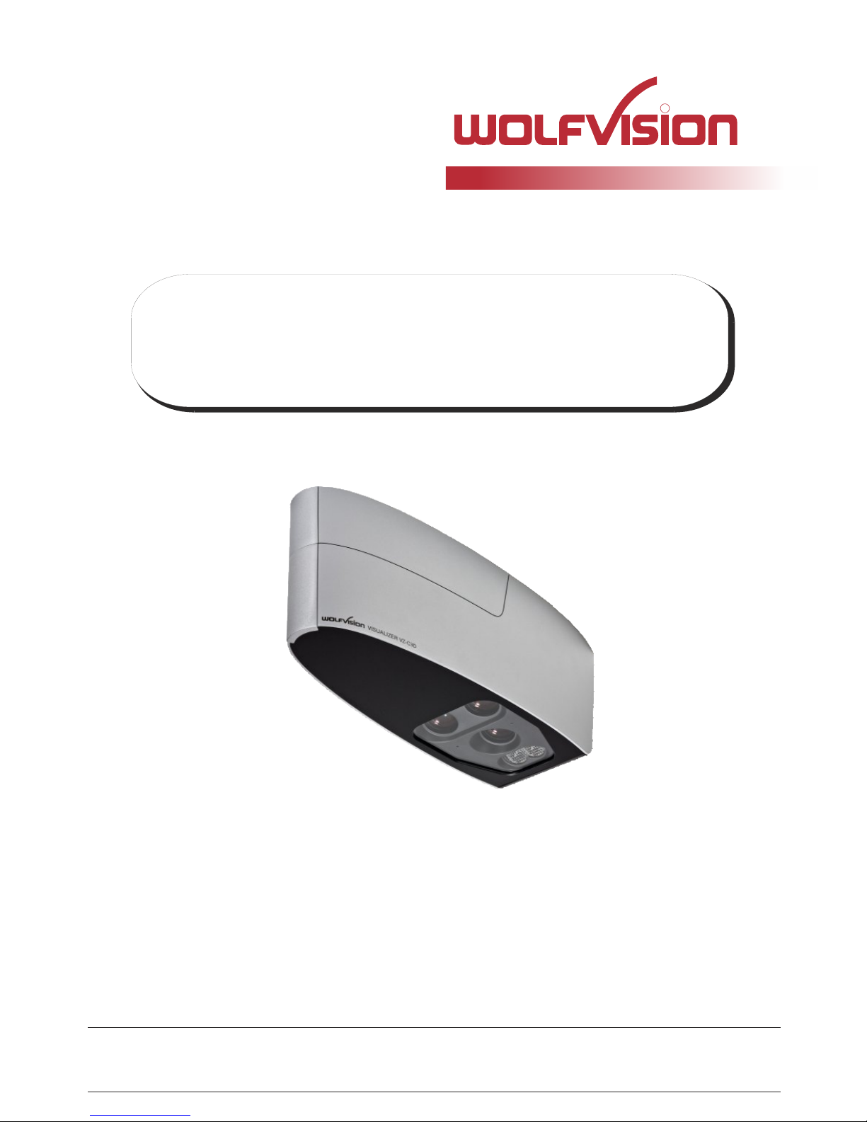
VZ-C3D
INSTRUCTIONS
BEDIENUNGSANLEITUNG
INSTRUCTIONS
BEDIENUNGSANLEITUNG
ENGLISH / DEUTSCH
VZ-C3D
R
Precautions
ENGLISH
Please observe the following:
Risk of electric shock
Dangerous voltage inside
WARNING!
CAUTION! INSTALLATION AND SERVICING OF THE VISUALIZER MUST BE PERFORMED BY
QUALIFIED SERVICE/INSTALLATION PERSONNEL FOLLOWING THE MANUFACTURER'S
INSTALLATION INSTRUCTIONS AND IN COMPLIANCE WITH THE NATIONAL ELECTRIC CODE,
ALL LOCAL BUILDING AND SAFETY CODES AND ALL OTHER APPLICABLE CODE PROVISIONS
OR REGULATIONS.
USE THIS UNIT ONLY WITH THE CORRECT VOLTAGE AS SHOWN ON THE TYPE LABEL !
DO NOT EXPOSE THE UNIT TO HEAT OR MOISTURE !
PROTECT THE UNIT FROM EXCESSIVE SHOCKS !
USE SECURITY ROPE TO PREVENT IT FROM FALLING DOWN !
Make sure that sufficient air circulation for cooling the unit is possible (ventilation slots on top of
the unit)!
If there is any abnormality (abnormal noise, smell, smoke etc.) disconnect the unit from mains
immediately and contact your Visualizer dealer!
Do not use a damaged power cord. This may cause short circuits or electrical shocks!
To prevent danger, do not modify the unit or operate without the cover panel firmly in place!
Do not expose the unit to water, metallic objects or any flammable material.
Avoid installing the unit in locations exposed to strong magnetic fields or electrical currents.
Avoid installing the unit in environments where there is radiation. This could cause monitor image
distortion or damage to the camera sensor.
Do not pull the plug from the power socket with wet hands!
If the unit is not used for a long time, disconnect it from mains!
1
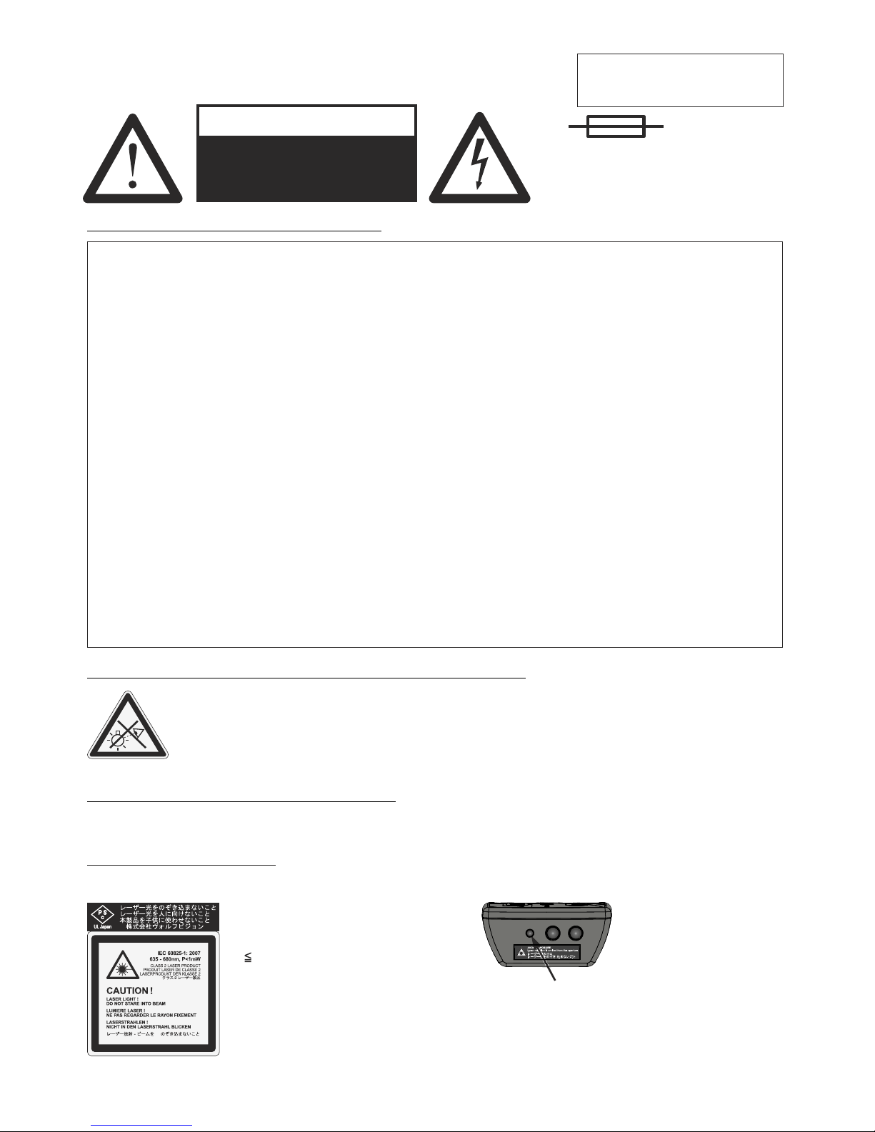
Precautions for the laser pointer:
Laser light - Do not stare into beam!
Do not modify the laser! Do not view the laser beam with optical instruments!
Information for laser pointer
FDA accession number: 9912688-00
This device complies with 21 CFR 1040.10 and 1040.11
The laser beam exits the
remote control through the
smaller (left) opening on
the front.
Technical data:
λ = 635 - 680nm
P< 1mW
Θ 2mrad
This label will be found on the
underneath of the remote
control.
Precautions for LED light according EN62471:
LED lighting system - Do not stare into beam!
Do not modify the LED lighting system!
Do not view the light beam with optical instruments!
Ne pas regarder dans l'objectif lorsque le visualiseur est en marche!
N
CAUTION
Double pole / neutral fusing.
ATTENTION
Double pôle / fible sur le neutre
2
EU 0 362 737 KR 128059 AU 765617
DE P58907684.1-08 US 5,027,219 CN ZL99118847.0
CN 89107780.4 EU 0 987 874 and others
JP 1725033 JP 3 544 900
FCC information:
This device complies with part 15 of the FCC rules. Operation is subject to the following two conditions: (1)
this device may not cause harmful interference, and (2) this device must accept any interference received,
including interference that may cause undesired operation.
Note:
This equipment has been tested and found to comply with the limits for a class B digital device, pursuant to
part 15 of the FCC rules.
Information to user:
The user manual or instruction manual for an intentional or unintentional radiator shall caution the user that
changes or modifications not expressly approved by the party responsible for compliance could void the
user's authority to operate the equipment.
This product is built according to Directive EMC and to Directive electrical equipment.
Inspections, tests and evaluation are according to UL 60950. CSA 22.22-60950
Inspections, tests and evaluation are according to the CB-Scheme
Inspections, tests and evaluation are according to the PCT-Scheme
Marks on the unit:
Approval
Worldwide Patents
Copyright Information
Copyright © by WolfVision. All rights reserved.
WolfVision, Wofu Vision and are registered trademarks of WolfVision Holding AG, Austria.
No part of this document may be copied, reproduced, or transmitted by any means, without prior written
permission from WolfVision. Except documentation kept by the purchaser for backup purposes.
In the interest of continuing product improvement, WolfVision reserves the right to change product
specifications without notice.
Information in this document may change without notice.
Disclaimer: WolfVision shall not be liable for technical or editorial errors or omissions.
The units are "MADE IN EU/AUSTRIA”
Printed in Austria, February 2015
US
C
L
I
S
T
E
D
9902476
Tested to complywith
FCC standards for
home or office use

Components of the Visualizer
#1 Lens for synchronized Lightfield
two identical camera systems for stereoscopic effect (twin cameras)
Connectors and Main Switch (behind the cover, as shown on next page)
Indication LED (see page 6) and IR-receiver (see page 13, external IR-receiver)
IR-remote control (see pages 4, 5 and 15)
#2 Camera lenses
#3 Cover to hide cable run and ceiling mount (pull up carefully, secured with cable rope)
#4
#6 Power
#5 Adapter Ceiling Mount to attach the Visualizer to the ceiling mount (see Installation Manual)
#7 Ambient Light (see page 8)
#8
#2
#3
#8
#6
#5
#4
#1
#7
3
Infrared Remote Control (#8)
4
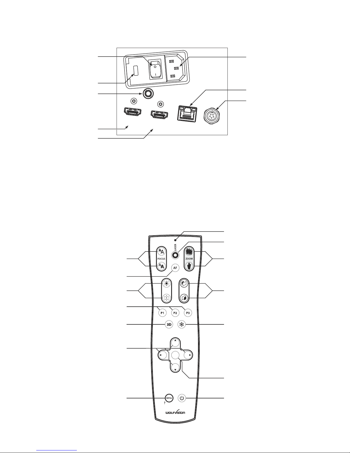
Connectors and Main Switch (#4)
#9
#10 HDMI Left output (see page 12)
#11
#13
#14
#15
#16
HDMI Right output (see page 12)
#12
Power connection to mains
LAN port (see pages 11 and 13)
MIC IN (see page 13)
Fuses (see page 15)
Main Power Switch
(multirange from 100 to 240VAC)
10/100 Tbase
IR-EXTERN input for additional IR-sensor (see page 13)
#14
#13
#15
#16
#12
#11
#9
#23
#25
#20
#29
#17 #30
#26
#22
#18
#28
#24
#19
#27
#21
IRIS VERG
OK
LAN
HDMI
3D / left
HDMI
3D / right
LAN
IR-EXTERN
T1.5A
FUSE
MIC IN
#10

5
#17 MENU key
Pressing MENU key activates the on-screen menu (see page 14).
#18 MENU NAVIGATION keys
For navigating through the on-screen menu (see page 14).
#19 3D key
To toggle image output between different 3D / 2D modes (see page 12).
#20 PRESET keys (programmable settings)
For storing a preset, press one of the PRESET keys for more than 2 seconds.
For recalling a preset, press the PRESET key quickly (see page 9).
#21 Manual IRIS keys (brightness adjustment)
When the IRIS keys are pressed, the Visualizer switches off the auto iris function. The next time the ZOOM
keys are used the auto iris is switched on again (see page 9).
For specialists: The behaviour of the iris can be changed in the on-screen menu.
The overall iris level can be changed in the on-screen menu (see page 14).
#22 AUTO FOCUS (AF) key
Pressing this key activates the Auto Focus (see page 9).
#23 Manual FOCUS keys
For focusing the picture (see page 9).
#24 LASER POINTER indication LED
Indicates active Laser LED.
#25 LASER POINTER key
Important: Do not stare directly into the laser beam. This is hazardous for your eyes!
#26 ZOOM keys
Using the ZOOM keys also switches auto iris on again.
#27 VERG keys
To adjust the (Con)vergence / deepth of the 3D effect (see page 12).
#28 FREEZE key
Freezes the current image (see page 9).
#29 OK key (Enter)
To confirm menu settings and to enter menu sub menus (see page 14).
#30 POWER key
Pressing this key switches the unit on and off.
When switching on the unit, the Visualizer runs the power-on preset.
Keys on the IR-Remote Control
If you want to work with more than one Visualizer in the same room, the units should be set to different
infrared codes, in order to control them all individually.
The IR code of the Visualizer has to match the code of the remote control.
To change the IR code, enter the "Advanced Settings / Miscellaneous Settings" and
set the "IR Code" to A, B, C or D (code A is default). To change the IR code on the remote control,
simultaneously press PRESET 1, PRESET 2 and ZOOM TELE
ress PRESET 1, PRESET 2 and ZOOM WIDE
on-screen menu, go to
(#20) (#26). Each time this key
combination is used, the code switches from A to B, C, D ... A ...in the given order.
For resetting the remote control to code A, simultaneously p .
The LED shows the selected code (it flashes one time for code A, two times for code B, three times for code
C and four times for code D).
Different IR Codes

1. Connect the power cable to the unit and plug it in (#14)
2. Connect a 3D viewing monitor or a 3D projector to the outputs of the Visualizer
For choosing the right output mode please see page 12!
3. Turn the main power switch (#13) on the unit to "I". The power indication LED on the unit is illuminated.
red for StandBy and green for fully powered-up.
4. By default, the Visualizer will be fully powered-up when mains is supplied.
When the default behaviour is changed by the user, press the POWER key (#30) on the remote control .
5. The Visualizer now runs the “power-on preset”.
When the Visualizer is switched on the first time, the Quick Setup Guide will be started automatically onscreen (visible on HDMI output). Use the arrow keys to navigate through the menu
Language
Select the desired language for the on-screen menu.
Height Adjustment
.
For usual installations, WolfVision recommends using the function “Auto Height Adjustment”. Should the unit
be unable to adjust itself (e.g. bright ambient light), please use the “Manual Height Adjustment” instead.
The Height Adjustment procedure can be repeated at any time. Just enter the on-screen menu and select
Advanced Settings / Height Adjustment.
Ethernet Settings
The IP-address, Subnet Mask and Gateway IP-address can be set automatically by a DHCP-server or
manually.
Power Settings
The cameras of the Visualizer can be optimized to 50Hz or 60Hz mains frequency to reduce flickering.
Time Settings
The Visualizer offers the possibility to use the internal clock or an external time server (a time valid time
server IP address and internet connection are required).
.
The settings are:
It is only necessary to conduct the Height Adjustment procedure once, unless the distance between the
Visualizer and working surface is changed
Note: The Height Adjustment is a one time setup, which must only be performed again if the distance
between the Visualizer and table is changed! - more details in the installation manual
Basic Preparations
Operating the Visualizer for the first time - Quick Setup Guide
6
Power-on preset:
Automatically zooms to a middle zoom position, focuses on the working surface and activates the auto iris
(the pick-up size is dependent on the mounting height of the Visualizer).
As soon as the Power Indication LED is green and stays illuminated, you can start working with the
Visualizer. The behavior of the unit once the power has been supplied or after the POWER key has been
pressed can be changed in the unit's on-screen menu (see page 14).
Picture Center
15°
public
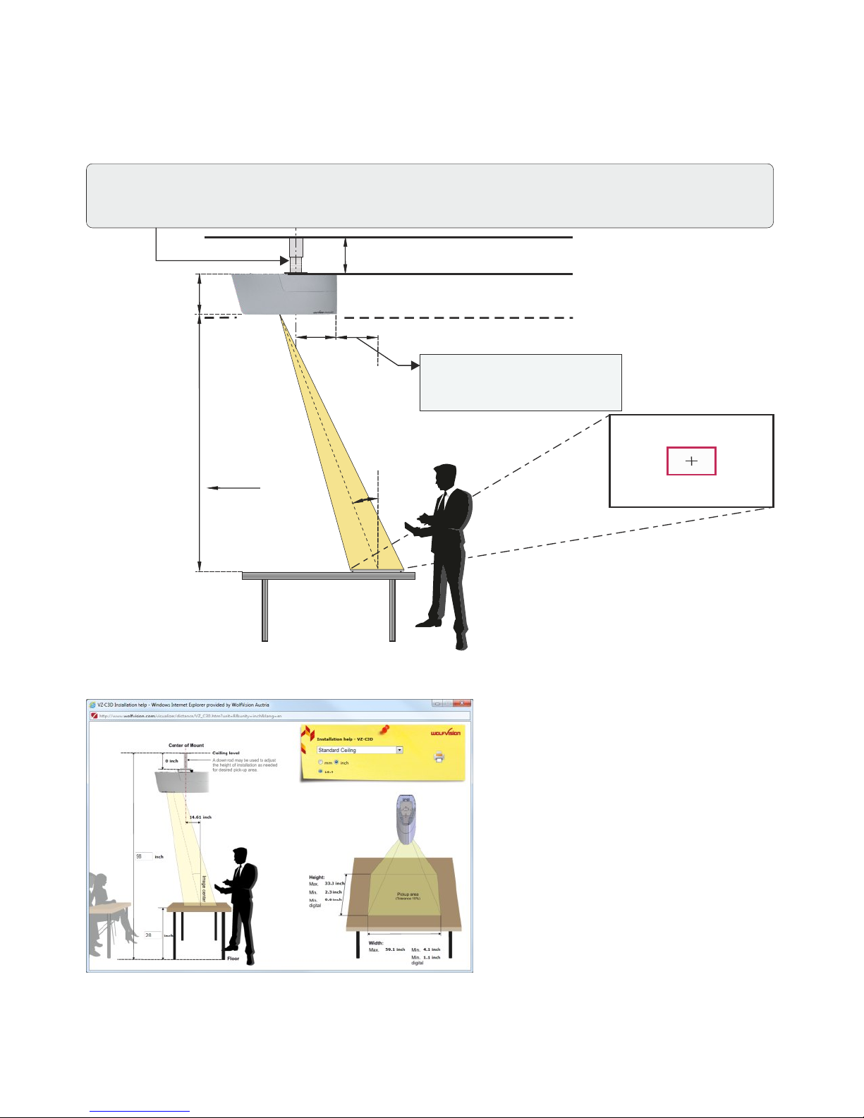
Read Installation Manual
before installing or uninstalling the unit!
Distance from bottom of the Ceiling
Visualizer to top of the working surface
178 mm
[7 inch]
x
suspended ceiling
(if required)
distant ceiling
ceiling
209
[8.23]
size of ceiling mount
(depending on model)
x mm = distance * tan 15° - 260mm
x" = distance * tan 15° - 10.24"
see installation manual for more details
(tan 15° = 0.2679)
screen
Installation
Please read the installation manual before fixing the assembly to the ceiling.
The size of the smallest and largest image that the unit can pick up is not fixed. This is dependent on the
distance between the working surface and the bottom of the Visualizer. The tables in the installation manual
show the pick-up sizes in relation to the mounting height:
In extremely high rooms the smallest image the unit can pick-up may not be small enough.
In such cases a standard ceiling mount or projector-lift can be used to suspend the Ceiling
Visualizer further from the ceiling.
Use the calculation program on WolfVision's internet homepage to calculate the exact position and image
sizes:
7
These figures may vary a little in reality,
because the position of the focus
influences the size. Masking of the monitor
or projector should also be taken into
consideration (e.g. some units cut off the
edges of the picture). Theoretically larger
distances than 2200mm (approx. 87") are
possible, but the pick-up size would be too
large and the light output too low.
www.wolfvision.com (Support)
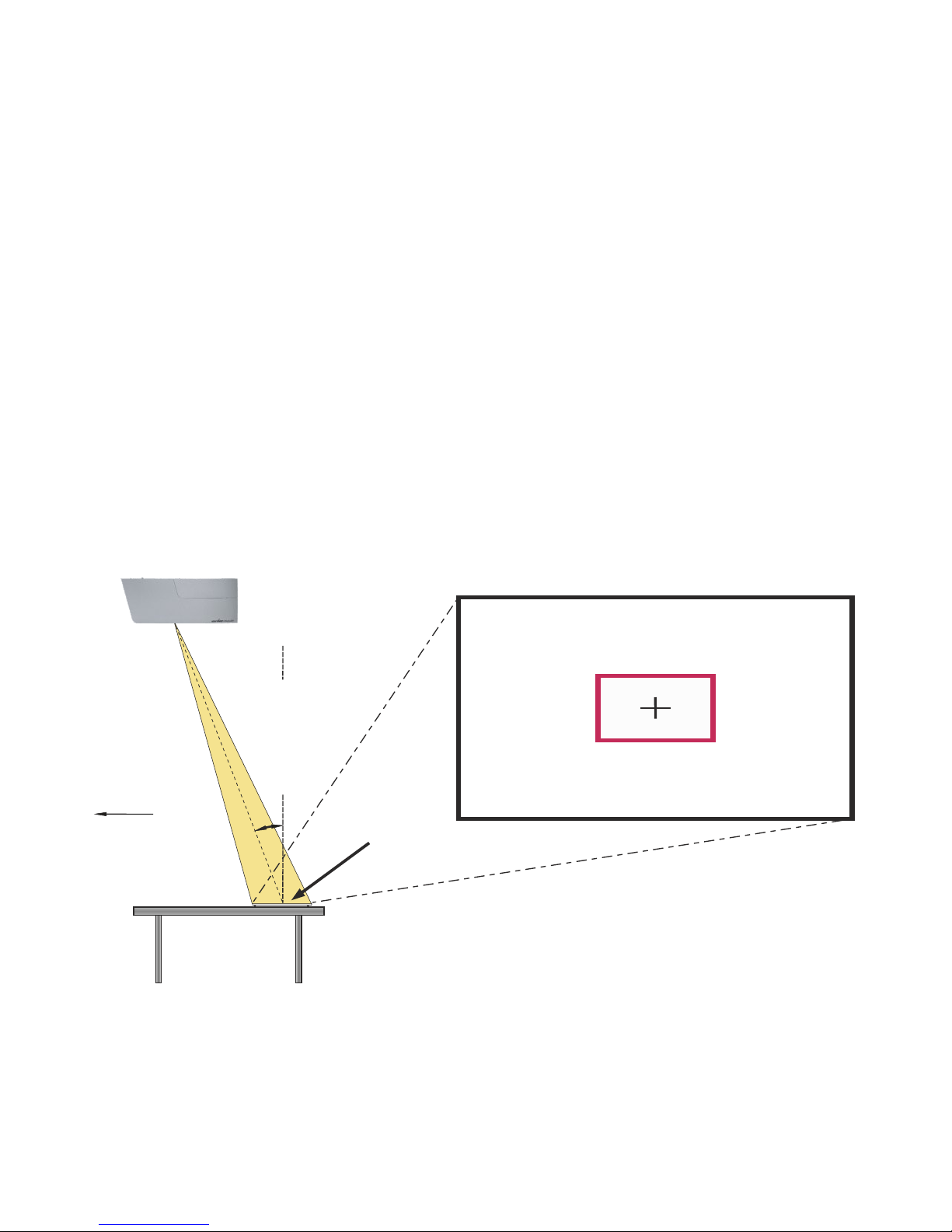
If the top light of the Visualizer is used (default) a synchronized lightfield always marks the pick-up area of
the built-in camera on the working surface.
The alignment of this lightfield is made for working on the working surface. Due to the oblique mounting of
the cameras and the light projector of the Visualizer, the lightfield shifts to the upper edge of the pick-up
area when the distance between the Visualizer and the scanned object is decreased (when capturing tall
objects).
This means that the lightfield no longer exactly shows the recorded area. In this case switch off the light of
the Visualizer by pressing the assigned PRESET key (LIGHT) and work with room light.
Synchronized Lightfield
1. The synchronized lightfield on the working surface marks the pick-up area of the built-in camera.
Just place your subject material in the illuminated area.
Please note, the lightfield is slightly bigger than the camera pick-up area due to technical reasons.
2. Select the enlargement required with the ZOOM keys (#26).
3. When the image is out of focus, adjust the sharpness with the FOCUS keys (#23).
Shooting Area On The Working Surface
8
To increase the light intensity on the working area, the Visualizer is equipped with an ambient light.
The ambient light cannot mark the pick-up area exactly.
By default, the ambient light will be switched off when zooming to wide at zoom factor x12.
The behavior of the Ambient light can be changed in the on-screen menu (see page 14).
Ambient Lightfield
Picture center
15°
public
screen
Synchronized
lightfield

Please note that the Visualizer has an optical 15x zoom. The digital 4x zoom increases the overall zoom
range to a 60x zoom. The pickup sizes are dependent on distance between Visualizer and object.
When you zoom in, the zoom will be stopped at optical end position, when you zoom in further the digital
zoom is automatically activated to extend the optical tele.
However please be aware that when the digital zoom is used, the resolution of the picture is not as good as
before.
The behavior of the Visualizer in the digital zoom mode can be changed in the on-screen menu (see page
14).
Optical Zoom / Digital Zoom
When the Visualizer is turned on the focus automatically adjusts to the object.
Please note that objects with very low contrast (like blank sheets of paper) are difficult to focus.
For special applications the autofocus can also be switched off using the on/off switch (#22). The autofocus
is also switched off when the manual FOCUS keys (#23) are used.
Focusing / Autofocus
WolfVision Visualizers are equipped with an auto iris. This means that the brightness of the camera image
adjusts automatically. Using the IRIS keys (#21) the auto iris function is switched off. In this mode the Iris
can be adjusted manually.
When using the ZOOM keys (#26) the auto iris function is switched on again.
The standard auto iris level can be set brighter or darker in the unit's on-screen menu - see page 14.
Auto Iris / Manual Iris
The Visualizer offers the possibility to store the current settings as a Preset and recall them by just pressing
the respective PRESET key (#20) on the remote control.
For storing a reset adjust y function as required and then PRESET key
for 2 seconds . An on-screen message inform you when the Preset is stored.
Hint: in addition to the zoom position, the (con)vergence setting will be stored too.
As mentioned above, when presets are stored all current settings such as zoom, focus, iris etc. are also
stored. Contrary to this, a user also has the opportunity to assign specific functions such as "NEGATIVE",
"NEGATIVE/BLUE", "BLACK/WHITE", "FREEZE", "LIGHT", "RECORD START", "RECORD PAUSE",
"RECORD STOP", etc. to a PRESET key in the on-screen menu of the Visualizer (see page 14).
p : an press any one of the s on the
remote control or more will
Preset Function
9
The optical zoom in wide is limited at zoom ratio 12x by default.
When you zoom out, the zoom will be stopped at optical zoom position 12x, when you zoom out further the
zoom extension is automatically activated and the ambient light will be switched off.
The behavior of the optical zoom extension and the ambient light can be changed in the on-screen menu
(see page 14).
Optical Zoom Extension (Wide)
The current image can be captured by pressing the FREEZE key (#28).
This can be used to prepare the next object during the audience is watching the frozen image.
Freeze

Correct white balance adjustment is important for an exact color reproduction!
For an exact white balance, at least 10% of the recorded image should be white.
For a precise fixed white balance adjustment use the "One Push" white balance. This can be done by
pressing the assigned PRESET key for 2 seconds. When the white balance is stored an on-screen
message appears. Setting a "One Push" white balance switches off the "Auto Tracking" mode (when the
unit is switched off and on again the "Auto Tracking" mode will be reactivated).
For specialists: The Visualizer can be switched between "Auto Tracking", "One Push" and "Manual" white
balance mode in the on-screen menu (see page 14). If you work with negative transparencies and a light
box, use a blank (black in the image) part of the negative film for white balance adjustment! The "one Push"
white balance will be separately adjusted and stored for top light and external light (no light).
Each time the lighting condition changes, the Visualizer's camera must readjust its white balance, in order
to optimize the color reproduction. The lighting condition (color temperature) changes, for example, if
changing between the Visualizer's light and an external lightbox (optional bottom light) or if the room light is
turning on or off.
The standard setting of the Visualizer is "Auto Tracking" white balance.
(LIGHT)
Normally there is no need for a manual white balance adjustment. However, if the colors on the screen still
appear to be wrong, the white balance can be adjusted manually (one-push):
Hints to perform a One-Push white balance:
Top light (and room light):
Zoom in on a white object (e.g. a sheet of paper) until there is only white on the screen and press the
assigned PRESET key (LIGHT) for 2 seconds.
Optional Lightbox with transparencies:
Turn off the light of the Visualizer with the assigned PRESET key and switch on the lightbox. Remove
everything from the light box, zoom to the smallest picture size until there is only white on the screen and
press the assigned PRESET key (LIGHT) for 2 seconds.
Optional Lightbox with x-rays:
Turn off the light of the Visualizer and switch on the lightbox. Place an x-ray on the light box, zoom out
until the whole x-ray is picked up and press the assigned PRESET key (LIGHT) for 2 seconds.
Please note: False colors can also be due to wrong color settings of your projector or monitor. It is
recommended to adjust the white balance of the Visualizer at first and if the results are still not satisfactory,
the monitor or projector should be checked.
This means that the white balance
is continuously adjusted automatically.
White Balance Adjustment
IMPORTANT
10
Lightbox (optional)
When a lightbox is used, the top light of the Visualizer should be switched off with the assigned PRESET
key (LIGHT). Using a bottom light has the disadvantage that the Synchronized Lightfield of the top light no
longer marks the pick-up area of the built-in cameras.
The recommended lightbox for the Ceiling Visualizer is the WolfVision Lightbox LB-38.

11
Send Stream to Network
The Visualizer has a built-in streaming server which is capable of broadcasting video content over the
network.
Select desired streaming content (2D/3D) and frame rate (keep in mind, these settings are influencing the
network traffic).
To watch the stream with a third party application, just input the network URL into the address field:
Internet Browser, example: http://192.168.0.2 (select Live Capture)
The necessary IP address is the IP-address of the Visualizer (on-screen menu Advanced Settings /
Ethernet Settings). The Visualizer broadcasts the currently shown content of video (live camera) to the
network.
Media Player, example (VLC player): udp://@225.0.0.0:8800
The necessary IP address is the destination address of the Visualizer (on-screen menu Advanced
Settings / Streaming Settings).
Enable continuous streaming and the Visualizer broadcasts the currently shown content of video (live
camera) to the network.
For full functionality JAVA version 7 or higher is necessary when using a browser to listen.
For full functionality following ports are necessary: 80, 123, 50000, 50913, 50914, 50915, 50921 and 8800
(default).
Ensure that the IP-address and used ports are not blocked by any firewall.
Please note, some network routers are not able to forward multicast streams.
Prepare Ethernet connection and select Streaming Settings in the on-screen menu Advanced Settings.
There you can assign the IP address of the destination (for multicast select: 225.0.0.0 to 238.255.255.255;
with all other addresses the stream can be received at one destination only; 224.x.x.x and 239.x.x.x are
reserved.), port, streaming content and frame rate.
With mode setting ”AUTO” the Visualizer streams on demand only. The WolfVision vSolution Link Software
and most internet browsers can start the stream automatically. In case your browser or third party
application (media player) cannot start the streaming function, change the mode to ”Continuous” for
permanent streaming (please note the resulting network traffic).
Technical Background: UDP Multicast works like a broadcast - many clients are watching the same video
stream. In Multicast mode the bandwidth is always the same, no matter how many computers are
connected. However as many routers do not support Multicast, UDP Unicast can be used instead for pointto-point connection (one client is possible).
In TCP Singlecast mode each computer opens a separate connection to the Visualizer, which requires a lot
of bandwidth if many clients are connected (max. 128 connections).
Hints:
The Visualizer supports video recording in a multimedia-container format inclusive audio. Just assign the
recording funtions to the PRESET keys and start recording with "RECORD". The recording can be paused
and resumed with "PAUSE" and stopped with "STOP"
input the network URL into the address field
Hints:
Motion-JPEG (MJPG).
.
The recorded video files can be watched and processed on a computer with respective third party software.
The computer has to be in the same network as the Visualizer. Open the file explorer on the computer and
of the Visualizer in the format: \\xxx.xxx.xxx.xxx\data.
Example: \\192.168.0.100\data
The file will be recorded in FullHD, Side-By-Side, with video codec
Every file will be named with date and time stamp (JJMMDD-hhmmss). Example: 150209-094735.avi
On-screen messages are telling you if the recording is running, paused or stopped.
The Visualizer uses an built-in SSD-memory with 500GB storage (capacity for about 8h, according content).
Streaming will be stopped as soon video recording is started.
Please note, a video file is recorded each time you press the REC key. If file size exceeds 2GB, a new file will
be created automatically.
Video recording and network streaming cannot be used simultaneously.
Video - Recording Video Clips
 Loading...