

WolfVision VZ-C122, VZ-C32 Instructions Manual
R
INSTRUCTIONS
INSTRUCTIONS
BEDIENUNGSANLEITUNG
BEDIENUNGSANLEITUNG
VZ-C12² / VZ-C32
VZ-C12² / VZ-C32
ENGLISH / DEUTSCH
Check out our Internet Homepage for additional information
www.wolfvision.com/support
Precautions
ENGLISH
WARNING!
Risk of electric shock
Dangerous voltage inside
Please observe the following:
CAUTION! INSTALLATION AND SERVICING OF THE VISUALIZER MUST BE
PERFORMED BY QUALIFIED SERVICE/INSTALLATION PERSONNEL FOLLOWING
THE MANUFACTURER'S INSTALLATION INSTRUCTIONS AND IN COMPLIANCE
WITH THE NATIONAL ELECTRIC CODE, ALL LOCAL BUILDING AND SAFETY
CODES AND ALL OTHER APPLICABLE CODE PROVISIONS OR REGULATIONS.
PINCH POINT! MOVING FOLDING MECHANISM CAN CRUSH FINGERS.
KEEP HANDS CLEAR. LOCKOUT BEFORE SERVICING.
USE THIS UNIT ONLY WITH THE CORRECT VOLTAGE AS SHOWN ON THE TYPE
LABEL !
DO NOT EXPOSE THE UNIT TO HEAT OR MOISTURE !
PROTECT THE UNIT FROM EXCESSIVE SHOCKS !
Make sure that sufficient air circulation for cooling the unit is possible (ventilation
slots on the left and right side of the unit)!
If there is any abnormality (abnormal noise, smell, smoke etc.) disconnect the unit
from mains immediately and contact your Visualizer dealer!
Do not use a damaged power cord.
This may cause short circuits or electrical shocks!
To prevent danger, do not modify the unit or operate without the cover panel firmly
in place!
Do not expose the unit to water, metallic objects or any flammable material.
Avoid installing the unit in locations exposed to strong magnetic fields or electrical
currents.
Avoid installing the unit in environments where there is radiation.
This could cause monitor image distortion or damage to the CCD camera.
Do not pull the plug from the power socket with wet hands!
If the unit is not used for a long time, disconnect it from mains!
Precautions for laser pointer:
AVOID EXPOSURE -
Laser radiation is emitted
from this aperture.
LASER RADIATION - DO NOT
STARE INTO BEAM
650nm, P<1mW
CLASS II LASER PRODUCT
LASER RADIATION
DO NOT STARE INTO BEAM
CLASS 2 LASER PRODUCT
OUTPUT POWER <1mW
WAVELENGTH 650nm
EN 60825-1 March 1997
Laser information
FDA accession number:
9912688-00
This device complies with
21 CFR 1040.10 and 1040.11
1
Approval
C
Marks on the unit:
Tested to complywith
FCC standards for
home or office use
L
I
S
E
T
9902476
US
D
FCC information:
This device complies with part 15 of the FCC rules. Operation is subject to the following two
conditions: (1) this device may not cause harmful interference, and (2) this device must
accept any interference received, including interference that may cause undesired
operation.
Note:
This equipment has been tested and found to comply with the limits for a class B digital
device, pursuant to part 15 of the FCC rules.
Information to user:
The user manual or instruction manual for an intentional or unintentional radiator shall
caution the user that changes or modifications not expressly approved by the party
responsible for compliance could void the user's authority to operate the equipment.
This product is built according to Directive EMC and to Directive electrical equipment.
Inspections, tests and evaluation are according to UL 60950. CSA 22.22-60950
Inspections, tests and evaluation are according to the CB-Scheme
Inspections, tests and evaluation are according to the PCT-Scheme
Worldwide Patents
EU 0 362 737 KR 128059 AU 765617
DE P58907684.1-08 US 5,027,219 CN ZL99118847.0
CN 89107780.4 EU 0 987 874 and others
JP 1725033 JP 3 544 900
Copyright Information
Copyright © by WolfVision. All rights reserved.
WolfVision, Wofu Vision and are registered trademarks of
WolfVision Holding AG, Austria.
No part of this document may be copied, reproduced, or transmitted by any means, without
prior written permission from WolfVision. Except documentation kept by the purchaser for
backup purposes.
In the interest of continuing product improvement, WolfVision reserves the right to change
product specifications without notice.
Information in this document may change without notice.
Disclaimer: WolfVision shall not be liable for technical or editorial errors or omissions.
The units are "MADE IN EU/AUSTRIA”
Printed in Austria, January 2008
2
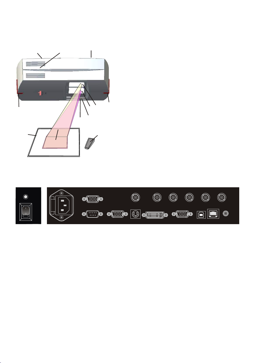
#11
#8
#10
#1 Mirror for light
(behind the glass cover)
#2 Mirror for camera
(behind the glass cover)
#3 Infrared-sensor (1x bottom)
#4 Infrared-sensor (2x side)
#5 Synchronized lightfield
#4
#4
#9
#5
#3
#7
#1
#2
#6
#6 Infrared Remote Control
#7 Main power switch and power
indication LED
(as shown below)
#8 Air extraction, ventilation (on both sides)
#9 Working surface
#10 Connectors (as shown below)
#11 Lamp exchange cover (see page 18)
Connectors (#10) and Main Switch (#7)
#13
#12
#14
RGB
RS-232
#19
#16
EXTERN IN
T3.15A
#15
#20
VIDEO
#17
S-VIDEO
#21 #22
G
R
B
V
H
#18
DVI
PREVIEW
#23
USB
#24
LAN
#25
IR-EXT.
#26
#12 Main Power Switch beside the glass cover
#13 Power Indication-LED beside the glass cover
#14 Fuses (see page 18)
#15 Power Connection
#16 RGB output 15-pin (see page 12)
#17 PAL/NTSC composite video output (see page 14) VZ-C32 only
#18 RGB output, BNC connectors (see page 12)
#19 RS-232 serial control input (see page 14)
#20 EXTERN IN external input for Computer RGB-signals (see page 13)
#21 PAL/NTSC Y/C (S-Video) output (see page 14) VZ-C32 only
#22 DVI output (see pages 12 and 14)
#23 PREVIEW RGB output (see page 12)
#24 USB port (see page 13)
#25 LAN 10/100 TBase (see page 13)
#26 IR-EXT. input for additional IR-sensor (see page 13)
3
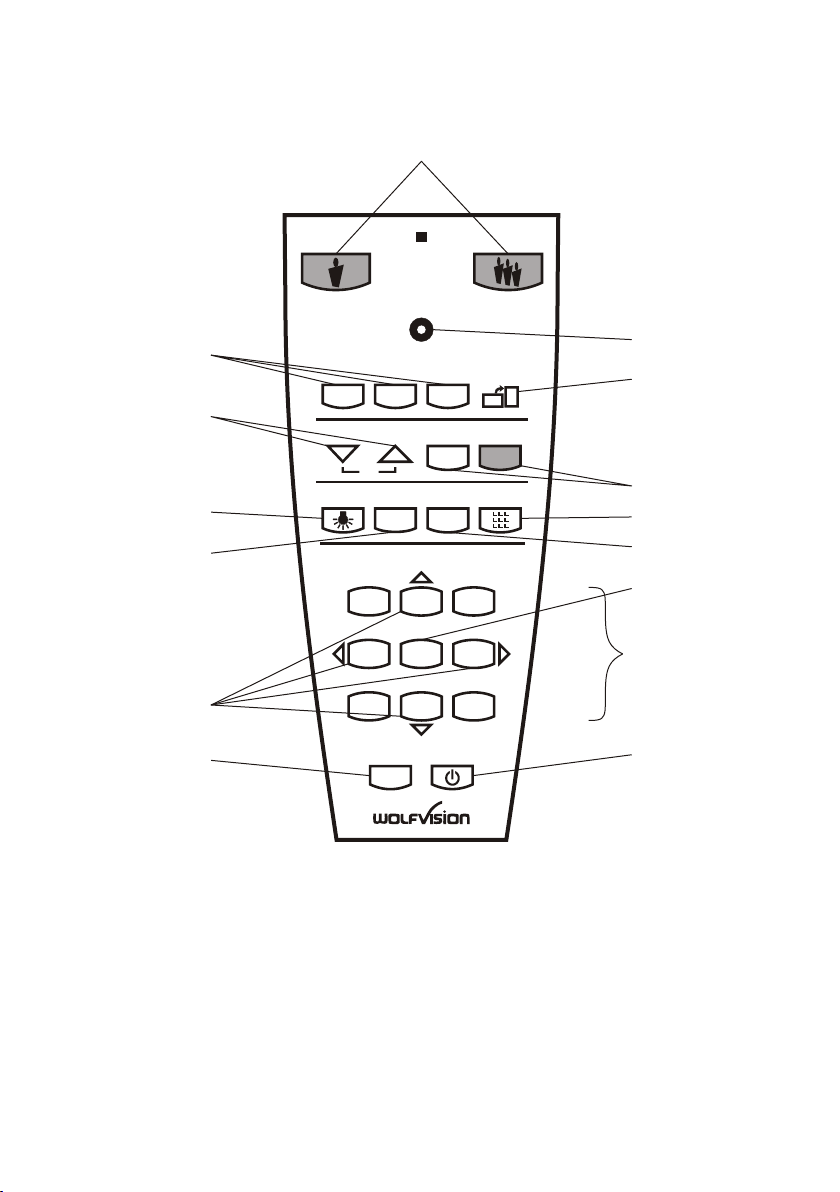
Infrared Remote Control (#6)
#27
#29
#31
#33
#34
#37
#40
PRESETS
2 3
MEMORY
HELP
MENU
LASER
EXT / INT
2
5
8
POWER
IMAGE TURN
AA
AA
ALLTEXT
3
6
9
TELE WIDE
1
FOCUS IRIS
AF
LIGHT
1
4
7
#28
#30
#32
#36
#35
#38
#39
#41
4

#27 ZOOM keys
Using the ZOOM keys also switches auto iris on again.
For specialists: The behaviour of the iris can be changed in the on-screen menu (see page 15).
#28 LASER POINTER key
Important: Do not stare directly into the laser beam.
This is hazardous for your eyes!
#29 PRESET keys (programmable settings)
For storing a preset, press one of the PRESET keys for more than 2 seconds. For recalling
a preset, press the PRESET key quickly (see page 9).
#30 IMAGE TURN mode key
For picking up vertical (portrait) pages with higher resolution (see page 10).
#31 Manual FOCUS keys
For focusing the picture.
By pressing both FOCUS keys an on-push autofocus will be performed (see page 9).
#32 Manual IRIS keys (brightness adjustment)
When the IRIS keys are pressed, the Visualizer switches off the auto iris function. The next
time the ZOOM keys are used the auto iris is switched on again (see page 9).
For specialists: The overall iris level can be changed in the on-screen menu (see page 15).
#33 Light key
Switches the light on and off (see page 8).
By pressing the LIGHT key for 2 seconds, an one-push white balance will be performed
(see page 11).
#34 TEXT Enhancement key
Improves the contrast for better readability (see page 10).
#35 EXT/INT key
Switches between Visualizer image and external input (see page 13).
#36 ALL key
For displaying all 9 pictures of the memory as split image (see page 10).
#37 SELECT keys (MEMORY keys 2, 4, 6 and 8)
For navigating through the on-screen menu (see page 15).
#38 HELP/RESET key for on-screen menu (MEMORY key 5)
While you are in the on-screen menu you can activate the on-screen help by pressing the
HELP key. Pressing this key for 2 seconds resets the selected menu item (see page 15).
#39 MEMORY keys 1 - 9
For saving and recalling pictures (see page 10).
#40 MENU key
Pressing this key for 1 second activates the on-screen menu (see page 15).
#41 POWER key
Pressing this key switches the unit on and off.
When switching on the unit, the Visualizer runs the power-on preset.
5
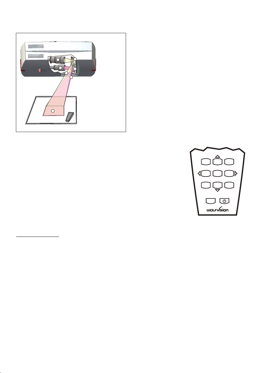
How The Visualizer Works
f
b
a
e
c
d
a) light projector
b) camera
c) image path
d) light path
e) mirror light
g
(motorized)
f) mirror camera
g) pickup area /
synchronized
lightfield
A light projector (a) inside the unit projects a
lightfield (g) the same size as the pick-up
area of the built-in camera via the mirror (e)
onto the working surface. The image is
recorded by the camera (b) using the same
path via the mirror (f).
The lenses of the light projector (a) and the
camera (b) are synchronized. Thus the size
of the light field on the working surface
changes when the user changes the zoom
range of the camera.
This scanning and illumination system is a
worldwide patent from WolfVision.
Basic Preparations
1. Connect the power cable to the unit (#15) and plug it in
2. If you would like to use a control monitor, connect it to
the PREVIEW RGB output (#23)
3. Connect a large viewing monitor or a projector to one of
the outputs of the Visualizer
For choosing the right output mode please see page 12!
4. Turn the main power switch (#12) on the unit to "I".
1
4
7
MENU
MEMORY
2
HELP
5
8
3
6
9
POWER
The power indication LED on the unit is illuminated red
to indicate that power is supplied.
5. Press the POWER key (#41) on the remote control
The Visualizer now runs the “power-on preset” .
Power-on preset:
The automatic setting of zooming to an middle zoom position (pick-up size depends on
mounting height of the Visualizer), focus on the working surface level and the auto iris are
activated. As soon as the Power Indication LED is green and stays illuminated, you can
start working with the Visualizer. The behavior of the unit as soon as power is supplied or
after the POWER key has been pressed can be changed in the unit's on-screen menu (see
page 15).
The Unit Is Switched On The First Time
When the unit is turned on for the first time, the Height Adjustment starts automatically. The
Ceiling Visualizer is pre-set to a distance of 2 m (78.76"). In most installations the
installation height will be different to this, so the following adjustments must be performed:
1. Adjustment of camera and light focus
2. Alignment of lightfield and camera field
NOTE: This is a one time setup, which must only be performed again if the distance
between the Visualizer and table is changed! - more details in the installation manual
6
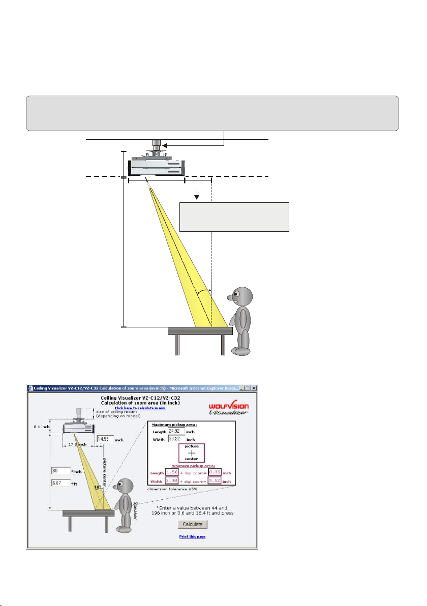
Installation
Please read first the Installation Manual before fixing the assembly to the room ceiling.
The size of the smallest and largest image that the unit can pick up is not fixed. It depends
on the distance between the working surface and the bottom of the Visualizer. The tables in
the installation manual show the relationship between mounting height and pick-up sizes:
In extremely high rooms the smallest image the unit can pick-up may not be small enough.
In such cases a standard ceiling mount or projector-lift can be used to suspend the Ceiling
Visualizer further from the ceiling.
ceiling
206 mm
8.11 inch
suspended ceiling
451.7 mm / 17.8 inch
x
x mm = distance * tan 18° - 291mm
x" = distance * tan 18° - 11.45"
see installation manual for more details
(tan 18° = 0.3249)
18°
(if required)
Distance (refer to calculation program)
Speaker
Before deinstallation the
unit please read first the
Installation Manual!
Use the calculation program on WolfVision's internet homepage to calculate the exact
position and image sizes :
The distance is measured from
the bottom of the Ceiling
Visualizer to the working
surface. These figures may
vary a little in reality, because
the position of the focus
influences the size. Masking of
the monitor or projector should
also be taken into
consideration (i.e. some units
cut off the edges of the picture).
Theoretically larger distances
than 4000mm (approx. 160")
are possible, but the pick-up
size would be too large and the
light output too low.
www.wolfvision.com/wolf/indexdistance.html
7
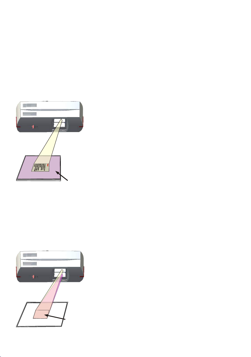
Synchronized Lightfield
If the top light of the Visualizer is used (default) a synchronized lightfield always marks the
pick-up area of the built-in camera on the working surface.
The alignment of this lightfield is made for working on the working surface.
Because of the oblique mounting of the camera and the light projector of the Visualizer, the
lightfield shifts to the right when the distance between the Visualizer and the scanned object
is decreased (when capturing high objects).
This means that the lightfield no longer exactly shows the recorded area. In this case switch
off the light of the Visualizer by pressing the LIGHT key (#33) and work with room light.
Working Surface / Light Box
The working surface of the Visualizer (#9) has a special
crystalline white color, which is especially designed for
perfect reproduction of transparencies.
Even if you own an optional light box, it is
recommended using the top light for
transparencies due to better color reproduction and
because the synchronized lightfield still shows the
pickup-area of the built-in camera.
In the following cases, the usage of an optional light
box is recommended:
- If the transparency is very dark such as x-rays
Lightbox
(optional)
- If the transparency is very wavy and causes
reflections
- If the room light causes reflections on
transparencies
When an optional light box is in use, the light of the
Visualizer should be switched off.
This has the disadvantage that the synchronized
lightfield of the top light no longer marks the pick-up
area of the built-in camera.
Shooting Area On The Working Surface
1. Place your subject material on the working surface.
A synchronized lightfield on the working surface
marks the pick-up area of the built-in camera.
Just place your subject material in the illuminated
area.
2. Select the enlargement required with the
ZOOM keys (#27).
3. When the image is out of focus, adjust the
Synchronized
l ghtfieldi
sharpness with the FOCUS keys (#31).
8
Focusing / One-Push Autofocus
When the Visualizer is turned on the focus automatically adjusts to the
FOCUS
AF
working surface level. As a result it is not necessary to readjust the focus, if you are only
working with flat material (text, photos etc.).
Due to the great depth in focus of the Visualizer, the focus rarely needs to be adjusted.
Only very high objects require a focus adjustment.
To activate the One-Push Auto focus, press both FOCUS keys (#31) simultaneously.
Please note that objects with a very low contrast (like a blank paper) are difficult to focus.
Digital Zoom
Please note that the Visualizer has an optical 16x zoom. The digital 4x zoom increases the
overall zoom range to a 64x zoom. However please be aware that when the digital zoom is
used, the resolution of the picture is not as high as before.
The default setting displays a message on-screen when you are in the digital zoom mode.
Still pictures in the memory can also be digitally zoomed.
You can change the behavior of the Visualizer in the digital zoom mode in the on-screen menu (see page 15).
Auto Iirs / Manual Iris
IRIS
WolfVision Visualizers are equipped with an auto iris. This means that the
brightness of the camera image adjusts automatically. Using the IRIS keys (#32) the auto
iris function is switched off. In this mode the Iris can be adjusted manually.
When using the ZOOM keys (#27) the auto iris function is switched on again.
Before the iris closes completely, the Visualizer automatically dims the light.
The standard auto iris level can be set brighter or darker in the unit's on-screen menu
- see page 15 and on-screen help.
Preset Function
1
PRESETS
2 3
The Visualizer offers the possibility to store the current settings as a
Preset and recall them by just pressing the respective PRESET key (#29) on the remote
control.
For storing a reset adjust y function as required and then PRESET
key for 2 seconds . An on-screen message inform you
s on the remote control or more will
p : an press any one of the
when the Preset is stored.
Additionally up to three different Height Adjustment settings can be assigned to the presets in
the on-screen menu.
As mentioned above, when presets are stored all current settings such as zoom, focus, iris
etc. are also stored. Contrary to this, a user also has the opportunity to assign only specific
functions such as "NEGATIVE", "NEGATIVE/BLUE", "BLACK/WHITE", "FREEZE" etc. to a
PRESET key in the on-screen menu of the Visualizer (see page 15).
Freeze
The current image can be frozen by pressing the programmed PRESET key 29 .
The behavior of the freeze function can be changed in the on-screen menu (see page 15).
(# )
9
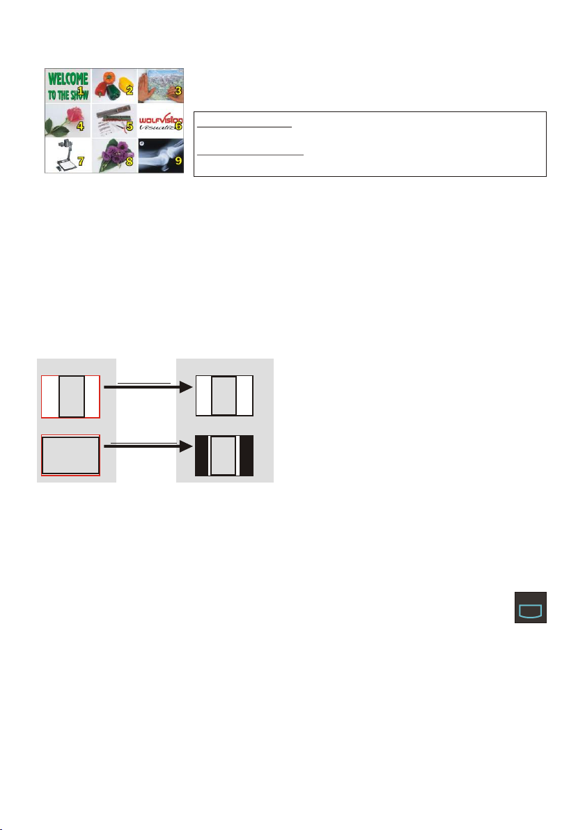
Image Memory for 9 images
You can store 9 images and recall them by just pressing one of
the numerical keys (#39) on the infrared remote control:
Storing an image: Press one of the MEMORY keys (#39)
for 2 seconds or more
Recalling an image: Press one of the MEMORY keys (#39)
quickly
Split image of 9 picture memory
By pressing the All key (#36) a split image with all 9 pictures of the memory can be
displayed.
When pressing the ALL key (#36) for 4 seconds, a menu appears on the screen asking if
you would like to erase all stored pictures (black picture) or if you would like to fill the
memory with “snapshots”. When choosing “snapshot” the Visualizer stores a new image
every second until all 9 memory locations are full. The Visualizer is equipped with a memory
backup battery. If the power has been interrupted any pictures in the memory will be stored
for up to 4 weeks.
The functional settings of memory erasing can be changed in the on-screen menu.
Image Turn Mode (for higher resolution)
Working surface:
A
A
Normal mode:
Only 50% of the
pixels are used to
pick up the document
Image turn mode:
90% of the pixels
are used to pick
up the document
Output picture:
A
A
Picking up a complete vertical (portrait)
document or A4 page has always been a
critical issue for a Visualizer because the
was
image always picked up in a horizontal
(landscape) format.
The camera could only use 50% of its pixels to
pick up a vertical (portrait) page. WolfVision's
"Image turn" mode solves this problem.
Just place your document (or other vertical object)º on the working surface horizontally and
zoom in on it completely, so that approx. 90% of the pixels of the built-in camera are used to
pick up the document, then press the IMAGE TURN key (#30). The Visualizer turns the
picture electronically 90 and outputs correctly with a much higher resolution than in
normal mode. The left and right margins will be black.
Text Enhancement
For improving the readability of text, sketches or x-rays, the text
mode can be activated by pressing the TEXT key (#34).
This mode enhances the contrast of the picture. Please note that the colors are now darker
than usual. To switch off the text enhancement mode, press the TEXT key again. When the
text enhancement mode is in use, the message "TEXT" is displayed on the output and the
TEXT key on the control panel is illuminated red.
This should remind the user to switch off the text mode when it is no longer required. It
should also prevent users trying to correct dark colors by opening the iris, resulting in a
poorly adjusted picture.
10
TEXT

White Balance Adjustment
IMPORTANT
LIGHT
Correct white balance adjustment is important for an exact color reproduction!
Each time the lighting condition changes, the Visualizer's camera must readjust its white
balance, in order to optimize the color reproduction. The lighting condition (color
temperature) changes, for example, if changing between Visualizer's light and an external
lightbox (bottom light) or if room light is turning on or off.
The standard settings of the Visualizer are the following:
When the Visualizer's light is switched on: fixed white balance.
When the Visualizer's light is switched off: "auto-tracking" white balance.
the white balance is continuously adjusted automatically.
This means that
For an exact white balance, at least 10% of the recorded image should be white
(measurement area is the center of the image).
For a precise fixed white balance adjustment use the "One Push" white balance. This can
be done by pressing the LIGHT key (#33) for 2 seconds. When the white balance is stored
an on-screen message appears. Setting a "One Push" white balance switches off the "Auto
Tracking" mode (When the unit is switched off and on again the "Auto Tracking" mode will
be reactivated).
Normally there is no need for a manual white balance adjustment. However, if the colors on
the screen still appear to be wrong, the white balance can be adjusted manually (one-push):
Hints to perform an One-Push white balance:
Top light: Zoom in on a white object (i.e. a sheet of paper) until there is only white on the
screen, press the LIGHT key for 2 seconds.
Lightbox with transparencies: Turn off the light of the Visualizer with the LIGHT key and
switch on the lightbox. Remove everything from the light box and zoom to the smallest
picture size until there is only white on the screen, press the LIGHT key for 2 seconds.
Lightbox with x-rays: Turn off the light of the Visualizer and switch on the lightbox. Place
an x-ray on the light box and zoom out until the whole x-ray is picked up, press the LIGHT
key for 2 seconds.
Please note: False colors can also be due to wrong color settings of your projector or
monitor. It is recommended to adjust the white balance of the Visualizer at first and if the
results are still not satisfactory, monitor or projector should be checked.
For specialists: The Visualizer can be switched between "Auto Tracking", "One Push" and "Manual"
white balance mode in the on-screen menu (see page 15). If you work with negative transparencies
and a light box, use a blank (black in the image) part of the negative film for white balance adjustment!
The "one Push" white balance will be separately adjusted and stored for top light and external light.
11

Choosing the Correct Output Mode
The DVI and RGB outputs (#16, #18, #22 and #23) can output signals in following formats:
- VGA (4:3 - 640x480 pixels) at 60Hz
- SVGA (4:3 - 800x600 pixels) at 60Hz, 75Hz or 85Hz
- XGA (4:3 - 1024x768 pixels) at 60Hz, 75Hz or 85Hz
- SXGA- (4:3 - 1280x960 pixels) at 60Hz or 85Hz
- SXGA ( - 1280x1024 pixels) at 60Hz or 75Hz
- SXGA+ (4:3 - 1400x1050 pixels) at 60Hz or 75Hz
- UXGA (4:3 - 1600x1200 pixels) at 60Hz
- XGA 16:9 (special format for non-HDTV capable 16:9-Plasma displays) at 60Hz
- WXGA/60 (16:9 Widescreen - 1360x768 pixels) at 60Hz
- WSXGA+/60 (16:10 Widescreen - 1680x1050 pixels) at 60Hz
- 720p (16:9 Widescreen HD/HDTV - 1280x720 pixels) at 50Hz or 60 Hz
- 1080p (16:9 Widescreen HD/HDTV - 1920x1080 pixels) at 50Hz or 60Hz
The "Auto resolution" function is activated by default. In this mode the Visualizer
continuously checks which devices are connected to the RGB (#16, #18 and #23) and DVI
output (#22) and automatically sets the optimal output mode for each connected device
separately.
connected units or the cables* are not "Plug and Play" compatible. If the Visualizer can not
detect the resolution of the connected device, the output is set to the default of XGA/60Hz
on VZ-C32 and SXGA-/60Hz on VZ-C12².
(*Cables with plug and play compatibility must have a 15-pin plug on both ends with all pins connected, pin 9 is not
used).
If you can not use the "Auto resolution" function, you can select the output mode manually in
the on-screen menu of the Visualizer (see page 15).
In order to achieve the best picture quality you must set the outputs of the Visualizer to
match the native resolution of your display unit (e.g. LCD or DLP projector or monitor).
Important: What matters is the native resolution of the projector or monitor, not the maximum
resolution that it can display (in compressed mode). The native resolution is the actual
number of pixels of the built-in LCD display or DLP chip of a projector or monitor. Most LCD
or DLP projectors can also display higher resolutions than their native resolution, but only in
compressed mode and with inferior picture quality.
Do NOT set the output of the Visualizer to a higher standard than the native
resolution of your display unit!
If you output the Visualizer image on a CRT monitor or CRT projector, use an output mode
with 75 or 85Hz, because 60Hz may show a slight image flickering. For LCD/DLP projectors
or monitors and video conferencing units 60Hz is the best choice. If you are unsure what the
best mode is, read the user manual of the connected units.
Do not set a higher refresh rate than your monitor or projector can display, otherwise
the monitor or projector can be damaged!
Follow the instructions in the user manual of the connected units.
Please note, if 4:3 and 16:9 or 16:10 resolutions are used simultaneously, the 4:3 display
shows black bars on top and bottom. This is necessary to ensure that all displays show
the same image content.
- native image on VZ-C32
- native image on VZ-C12²
5:4
- native image on VZ-C12²
Please note that the Visualizer can not check the possible resolution, if the
12
External Infrared (IR) Sensor
In some rooms the 3 built-in infrared receivers of the Ceiling Visualizer may not be enough.
In this case connect the supplied external infrared receiver to the IR-sensor plug (#26) and
position the IR-sensor somewhere on the ceiling (or in the room) where the users normally
point the remote control at.
IMPORTANT
External Input / Scaler - EXT/INT
A computer can be connected to the EXTERN IN port (#20) of the Visualizer.
By pressing the EXT/INT key (#35) you can switch between the Visualizer image and the
image of the external input to be displayed to the audience.
The extern mode can also be used for only one output. The behavior can be changed in
the on-screen menu (see page 15).
The Visualizer has a built-in A/D-converter in order to digitize the analog RGB signal from
the computer and output it on all outputs in the selected signal format (allowed input
signals: from VGA to SXGA/75Hz).
With the built-in scaler, computer signals can be converted to the PAL/NTSC video standard
(VZ-C32 only).
Ethernet / LAN -Port 10BASE-T/100Base-TX
The LAN connection (#25) can be used for controlling the Visualizer over a computer
network. Image transfers, firmware updates, displaying status information and e-mail
notifications are possible.
The following protocols are supported: TCP/IP, ICMP and ARP.
d i b : /FirefoxSupporte nternet rowsers are Internet Explorer, Netscape Navigator and Mozilla .
By default, DHCP is activated to receive all settings automatically.
Image transfer resolution: still image: 1024x768 (or 512x384), live image: 160x120
Please check the separate ETHERNET / LAN description on our internet homepage at:
www.wolfvision.com/support (or on the supplied CD-Rom).
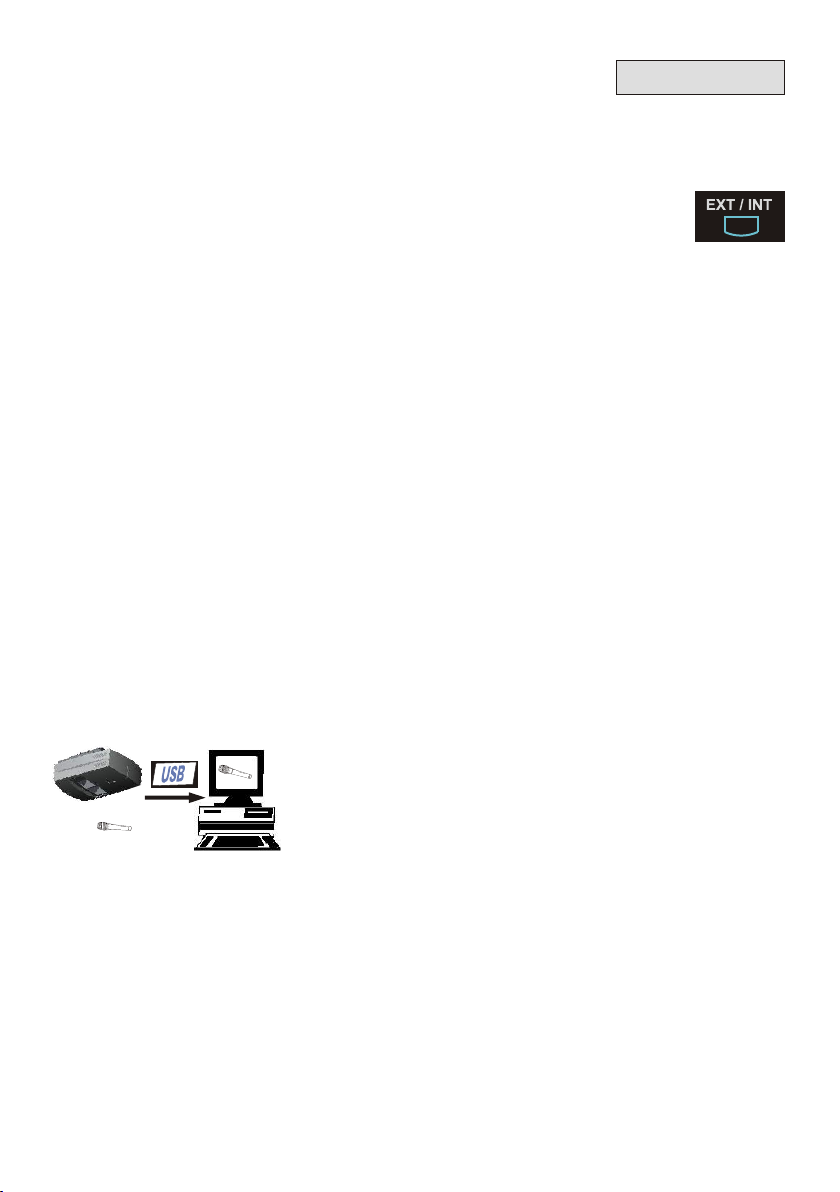
USB-Port
Connecting slower computers with the older USB 1.1 standard is also no problem. It still
takes only a small fraction of the time a desktop scanner requires to scan an image.
WolfVision's USB software works under Windows 98, ME, 2000, XP and Apple Macintosh
and is fully Twain compatible. This is important when using the Visualizer in connection with
popular graphic programs such as Photoshop, or for connecting them to Interactive
Whiteboards (Smart Boards).
The fast USB 2.0 port can also output live motion. The WolfVision USB software can store
AVI files and includes a video capture driver. You can view and save the live image from the
Visualizer on your computer in almost every modern video editing software.
The USB output (#24) of the Visualizer can be used to
transfer images from a Visualizer to a computer and save
them in JPG, TIF or BMP format. This way, Visualizers
can also be used as scanners for 3-dimensional objects.
WolfVision Visualizers are equipped with a fast USB 2.0
port. This allows uploading images onto a PC in a fraction
of a second.
13
 Loading...