

WolfVision VZ-27plus, VZ-57plus Instructions Manual
R
INSTRUCTIONS
INSTRUCTIONS
BEDIENUNGSANLEITUNG
BEDIENUNGSANLEITUNG
VZ-27plus / VZ-57plus
VZ-27plus / VZ-57plus
ENGLISH / DEUTSCH
Check out our Internet Homepage for additional information
www.wolfvision.com/support
Precautions
ENGLISH
WARNING!
Risk of electric shock
Dangerous voltage inside
Please follow these precautions:
USE THIS MACHINE ONLY WITH THE CORRECT VOLTAGE AS SHOWN ON THE TYPE LABEL !
DO NOT EXPOSE THE UNIT TO EXTREME HEAT OR MOISTURE !
DO NOT CARRY THE VISUALIZER HOLDING IT ONLY BY ITS MIRROR ARM (#1) !
PROTECT THE UNIT FROM EXCESSIVE SHOCKS !
Make sure that sufficient air circulation for cooling the unit is possible (ventilation slots on the left and
right side of the unit)!
If there is any abnormality (abnormal noise, smell, smoke etc.) disconnect the unit from mains immediately
and contact your Visualizer dealer!
Do not use a damaged power cord.
This may cause short circuits or electrical shocks!
Do not modify the Visualizer or operate it without the cover panel firmly in place, to prevent danger!
Do not expose the Visualizer to water, metallic objects or any flammable material.
Avoid installing the Visualizer in environments where there is radiation.
Avoid installing the Visualizer in locations exposed to strong magnetic fields or electrical currents. This
could cause monitor image distortion or damage to the CCD camera.
If the Visualizer is not used for a long time, disconnect it from mains!
Precautions for built-in laser pointer:
AVOID EXPOSURE -
Laser radiation is emitted
LASER RADIATION - DO NOT
STARE INTO BEAM
650nm, P<1mW
CLASS II LASER PRODUCT
from this aperture.
LASER RADIATION
DO NOT STARE INTO BEAM
CLASS 2 LASER PRODUCT
OUTPUT POWER <1mW
WAVELENGTH 650nm
EN 60825-1 March 1997
FDA accession
number:
9912688-00
This device
complies with
21 CFR 1040.10
and 1040.11
This product is built according to Directive EMC and to Directive electrical equipment.
This equipment has been tested and found to comply with the limits for a Class B digital device, pursuant to Part
15 of the FCC Rules. These limits are designed to provide reasonable protection against harmful interference when
the equipment is operated in a commercial environment. This equipment generates, uses, and can radiate radio
frequency energy and, if not installed and used in accordance with the instruction manual, may cause harmful
interference to radio communications. Operation of this equipment in a residential area is likely to cause harmful
interference in which case the user will be required to correct the interference at his own expense.
Inspections, tests and evaluation according to UL 60950. CSA 22.22-60950
Inspections, tests and evaluation according the CB-Scheme
The professional WolfVision Visualizer system was developed and designed by WolfVision in Austria.
Patents (examples): US 5027219, FRG 3833908, CH 678576.
Printed in Austria, September 2005 Design and specifications subject to change!
1
3
1
6
10
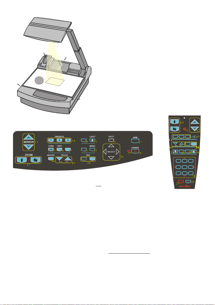
#1 Arm
#2 Base mirror
#3 Top mirror (sensing head)
#4 Control panel
#5 Synchronized lightfield (top light)
#6 Remote Control
#7 Ventilation, air outlet
2
#8 Ventilation, air inlet
#9 Working surface with built-in
7
11
5
9
4
8
Bottom light (removable)
#10 Connectors on the back
(see page 11, 12)
#11 Lamp exchange cover
under the removable bottom light
(see page 10)
CONTROL PANEL:
EXT/INT
FREEZE
A
A
AF
#12 Upper MIRROR up and down (for scrolling)
(Can also be moved by hand! This does not
cause any harm to the motor of this mirror!)
#13 ZOOM keys
#14 Three user programmable PRESETS
(see page 7)
#15 IMAGE TURN key (see page 6)
#16 TEXT Enhancement key improves the
contrast for better readability (see page 7)
#17 FREEZE key to freeze the current image
(see page 7)
#18 MACRO
For bigger enlargements (see page 5)
#19 Manual FOCUS adjustment (see page 5)
#20 EXT / INT switches between Visualizer
image and external input (see page 8)
#21 LIGHT switches between "Top light",
"Bottom light" and "Light off"
#22 WHITE activates one push
WHITE BALANCE adjustment (see page 7)
#23 MENU activates the on-screen menu
(see page 9)
WHITE
ZOOM MIRROR
LASER
PRESETS
IMAGE TURN
A
2 3
REMOTE
CONTROL:
1
FOCUS IRIS
AF
LIGHT
1
4
7
A
EXT / INT
ALLTEXT
MEMORY
3
2
HELP
5
6
9
8
POWER
MENU
#24 Manual IRIS makes image brighter or darker
(see page 5)
#25 HELP activates the on-screen help for the
on-screen menu. This key is only available
after pressing the MENU key (#23) for 1 sec.
#26 SELECT keys for on-screen menu (only
available after pressing the MENU key (#23)
for 1 sec.)
#27 Motorized ARM up and down
#28 (Standby) POWER on and off
#29 Power indication LED (red=off, green=on)
Only on remote control:
#30 ALL-key for displaying all 9 pictures of the
memory as split image (see page 8)
#31 MEMORY keys 1-9 (see page 8)
#32 LASER pointer key
Important: Do not stare directly into the beam.
This would be bad for your eyes!
2

HOW THE VISUALIZER WORKS
f
a) light projector
b) camera
c) light path
d) image path
e) base mirror
f) top mirror
g) pickup area /
synchronized
lightfield
c
d
e
g
a
b
BASIC PREPARATIONS
A light projector (a) inside the unit projects a
lightfield (g) the same size as the pick-up
area of the built-in camera via the base mirror
(e) and the top mirror (f) onto the working
surface. The image is recorded by the camera
(b) using the same path.
The lenses of the light projector (a) and the
camera (b) are synchronized. Thus the size of
the light field on the working surface changes
when the user changes the zoom range of the
camera.
This scanning and illumination system is a
worldwide patent from WolfVision.
1. Connect the power cable to the unit (#35) and plug it in.
2. If you would like to use a control monitor, connect it to the following outputs:
Computer monitors: Preview RGB output (#39)
Video monitors: Y/C (S-Video) output (#43) or Composite Video output (#44).
3. Connect a large viewing monitor or a projector to one of the outputs of the Visualizer.
For choosing the right output please read page 11 and 12!
4. Turn the main power switch (#33, on the back of the unit) to "I". The red power indicator
(#29) on the control panel indicates that power is supplied.
5. If the arm is folded down press the ARM-key (#27) on the control panel, then the arm
comes up automatically.
6. Press the POWER-key (#28) on the control panel.
The Visualizer now runs the "power-on preset" (=automatic focusing of an A5 format on
the working surface) during which the green LED light (#29) is flashing. As soon as
the green LED light stays illuminated you can start working with the Visualizer.
(The behaviour of the unit once that power is supplied to the unit or after the POWER-
key is pressed can be changed in the unit's menu - see page 9 and on-screen help)
3
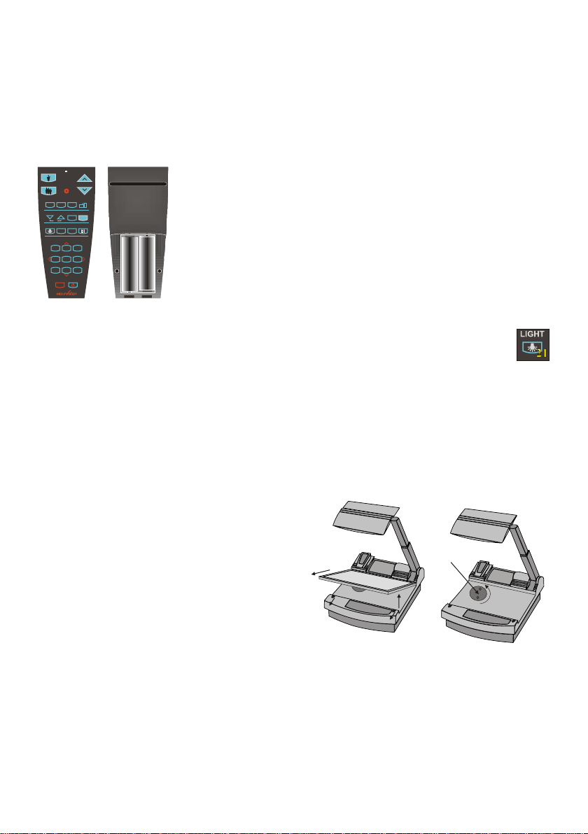
WORKING ON THE WORKING SURFACE
1. Place your subject material on the working surface.
A synchronized lightfield on the working surface marks the pick-up area
of the built-in camera! Just place your subject material in the illuminated
area.
2. Select the enlargement required with the ZOOM-keys (#13).
3. Use the MIRROR-keys (#12) on the control panel or the remote control to
change the vertical position of the pick-up area. The upper mirror can also
be moved by hand! This does not cause any harm to the motor of this
mirror!
DO NOT TOUCH THE MIRROR SURFACE, AS FINGERPRINTS
Synchronized
lightfield
CAUSE BRIGHT AND HAZY SPOTS ON THE PICTURE ! ALWAYS
KEEP THE MIRROR CLEAN ! - see page 13
CAUTION: SENSITIVE FRONT COATED MIRROR!
SYNCHRONIZED LIGHTFIELD
If the top light of the Visualizer is used (normal working condition) a synchronized lightfield
always marks the pick-up area of the built-in camera on the working surface.
The alignment of this lightfield is made for working on the working surface. Because of the oblique
mounting of the camera and the light projector of the Visualizer the lightfield shifts to the left when the
distance between the Visualizer and the scanned object is increased (when capturing images outside
of the working surface). This means that the lightfield no longer exactly shows the recorded area. In this
case switch off the Visualizer’s top light with the LIGHT-key (#21) and work with room light.
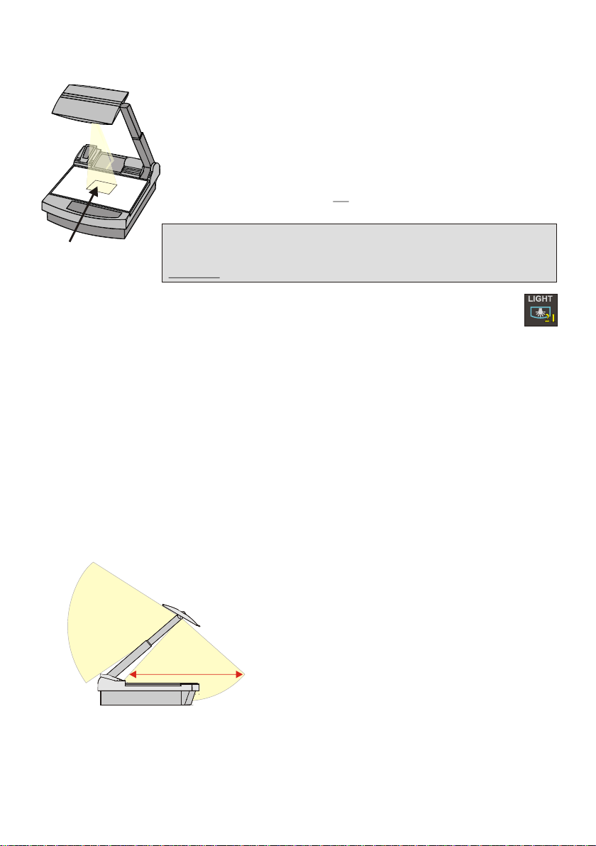
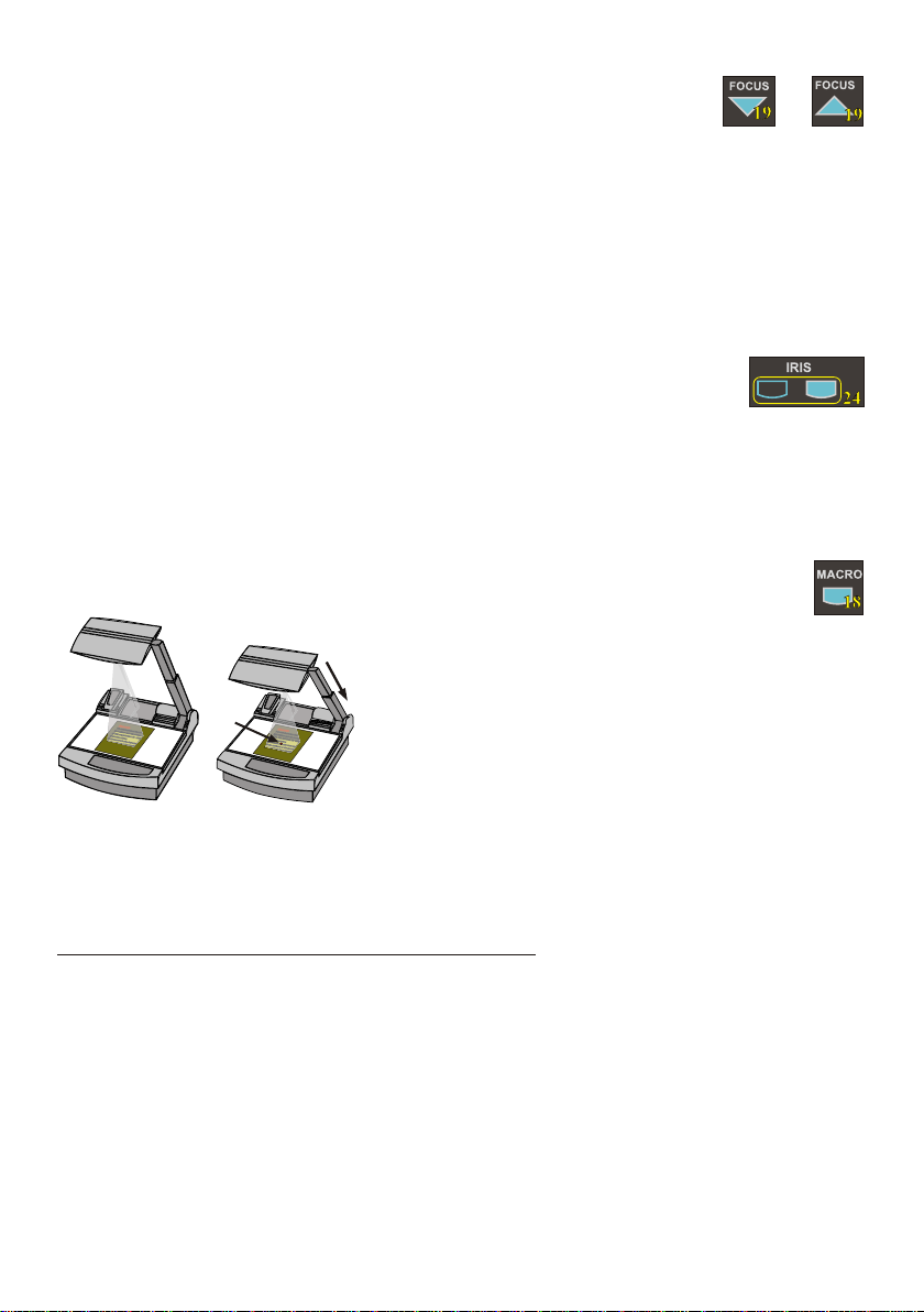
WORKING OUTSIDE THE WORKING SURFACE
For showing 3-dimensional objects with the WolfVision Visualizer, just place them on the working
surface and adjust ZOOM and FOCUS (as mentioned). Due to a special WolfVision lens the object can
be up to 25 cm (9.7") in height. If the object is to big for the working surface or if you want to show it
from the side just place it behind or in front of the unit and tilt the top mirror by hand or using the
MIRROR-keys (#12).
In this way it is also possible to make
recordings of objects in the room or
surrounding area, just like with a video
camera.
to infinity
700mm (27.6")
Due to the great focal range it is possible to
show details in every distance to the unit.
If you want to record people you should turn
off the light with the LIGHT-key (#21), so that
they are not blinded by the light.
4
FOCUSING
+
When the Visualizer is turned on the focus automatically adjusts to the working
surface level. As a result it is not necessary to readjust the focus if you are only working with flat
material (text, photos etc.). Furthermore, due to the great depth of focus of the Visualizer it is rarely
necessary to readjust the focus.
Only very high objects require a focus adjustment.
Pressing both FOCUS-keys (#19) simultaneously, activates a One-Push Auto focus.
(Please note that this is a new function, introduced in Mai 2005 with firmware Version 1.13a.
Units with older firmware perform an Auto focus for flat objects with this key combination.)
AUTO IRIS / MANUAL IRIS
WolfVision Visualizers are equipped with auto-iris. That means that the brightness of
the camera image adjusts automatically. Using the IRIS-keys (#24) the auto iris function is switched off.
In this mode the Iris can be adjusted manually.
When using the ZOOM-keys (#13) the auto iris function is switched on again. Before the iris closes
completely, the Visualizer automatically dims the light.
The standard auto iris level can be set brighter or darker in the unit's menu
- see page 9 and on-screen help.
MACRO MODE / 4x DIGITAL ZOOM
In the fully extended position of the arm, the smallest pick-up
area is 42 x 33mm (1.6" x 1.3").
Laser
center
P
l
ea
s no
e
e:
t
I
tisv im antth
e
r
y p
o
rt
l
i
gh
t so
s
h
a
i
n
e
n
a
t h
o
s ti
t
e
sm
c
s
e
ree
a
yin
t
p
rfe
r
o
j
r h
e t
c i
t
i
o
e
n
p
v
ideoh
c r
t
Fu h
u
e
t
.e
e
r o
m e
r i
t
tatth
i o
s a
ls
e
i
m
a
uienc o
por
d
t
an
d ot
o n
e
tr
r h
t p
g
e
es e e
t b
lin
ak
d
n
e
d r
db a
a
rh
y
a
rk
brigh li
om i
o
t h
.
g
t
marker
t t
n
os
r
ay
n
,
Pl
ea
se note:
It is
very import
lig
ant that no
ht s
hine
s
st
onto t
ra
as
th
h
e screen
is
may
in
,
te
proj
rfer
ec
e
tion pi
the
video
ct
Fu
ure.
rt
he
rm
ore it
th
is
at
a
lso import
th a
e
ud
ie
nc
ant
o
e
n
or
ot
th
get b
e
sp
lin
eaker
ded by a
in a d
ar
k room
b
right
.
lgh
id
t
When pressing the MACRO-key (#18) the length of the arm is
automatically reduced, this allows greater enlargements. In the
y
macro mode the smallest pick-up area with full optical
resolution is: 30 x 22mm (1.2" x 0.9"). When zooming in, the
zoom stops at this size.
If you press the ZOOM IN-key again after the stop, the unit activates its digital zoom extension. In this
mode you can zoom into a picture as small as 8 x 6mm (0.3" x 0.2”).
Please note that the resolution in the digital zoom area is lower!
The MACRO-key is illuminated in red color if the macro function is activated.
Please note that the macro mode has the following limitations:
- The depth of focus and the object height that can be focused is not as large as in the fully
extended arm position.
- The largest pick-up size is only about 42 x 33 mm (1.6" x 1.3").
- When zooming the Synchronized Lightfield stays at a larger size and no longer marks the pick-up
area of the built-in camera. The Laser Center Marker (see next chapter) is activated as a substitute.
If sufficient depth of focus and focusing high objects in the macro mode is more important than big
enlargements, it is possible to switch the Visualizer from 12x zoom to 11x zoom in the Visualizer's
menu (see page 9). The smallest pick-up size in the 11x macro mode is only 33 x 25mm (1.3" x 1"), but
the depth of focus is larger than in the 12x macro mode.
5
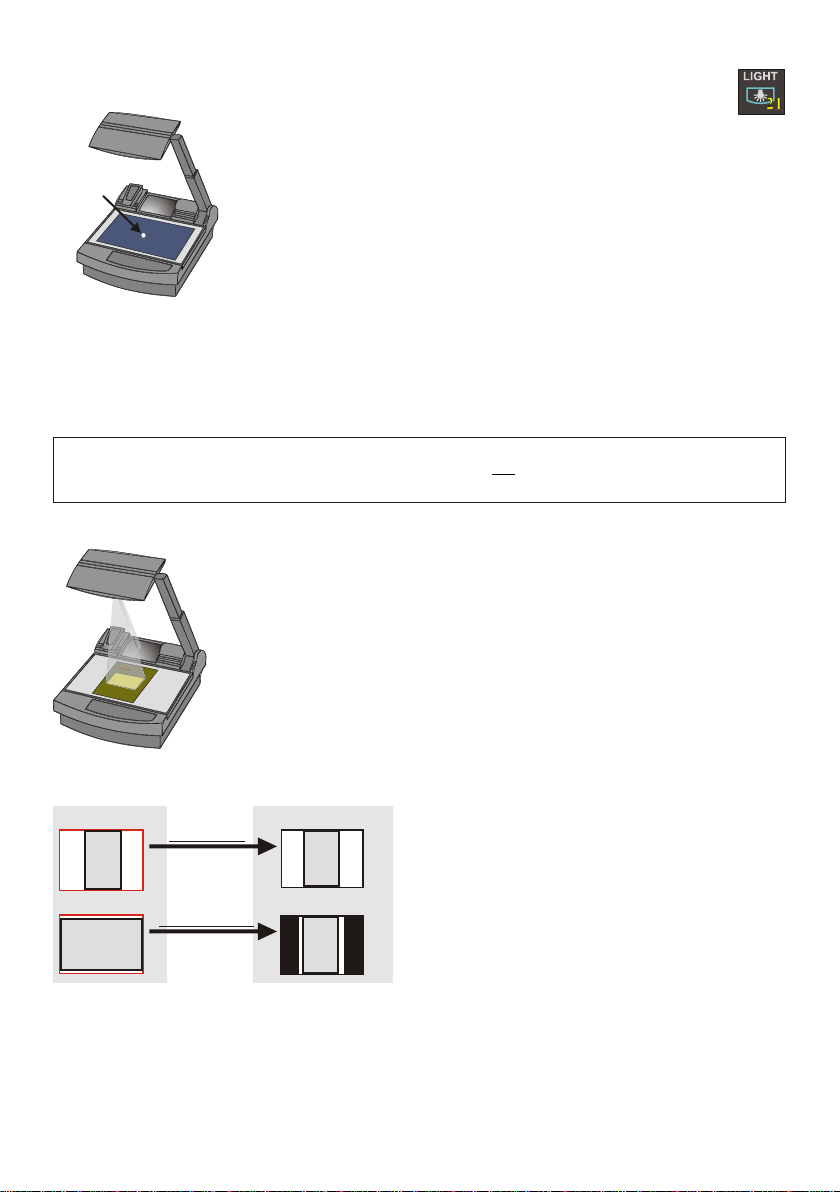
BOTTOM LIGHT / LASER CENTER MARKER
The LIGHT-key (#21) can be used to switch between:
"Top light" (with Synchronized Lightfield)
"Bottom light" with Laser Center Marker
Laser
center
marker
"Light off"
The bottom light should be used for dark transparent materials such as x-
rays or for very small transparent material such as slides.
Using the bottom light has the disadvantage that the Synchronized Lightfield
of the top light no longer marks the pick-up area of the built-in camera.
However as a substitute the Visualizer has a built-in Laser Center Marker,
which marks the center of the pick-up area. This can also be used for
positioning of objects (especially with big enlargements, like when picking
up a slide).
The Laser Center Marker is only visible on the working surface and NOT on the picture the audience
sees. For safety reasons the Laser Center Marker is automatically switched off when the top mirror is
tilted to record outside of the working surface. If required the Laser Center Marker can also be switched
off completely in the unit's menu (see page 9 and on-screen help menu).
Please note that for technical (optical) reasons the laser center marker can not show the exact middle
center of the pickup area in every position of the arm. This is not a failure of the unit! However it is
always very close to the center.
WORKING WITH TRANSPARENCIES
The working surface of the Visualizer (#9) has a special crystalline white color,
which is especially designed for perfect reproduction of transparencies.
Even though the professional Visualizers have a built-in bottom light it is
recommended to use the top light for transparencies, because of the better
color reproduction and the advantage that the Synchronized Lightfield still
P
le
ase note
:
It
i
s v
ery im
p
o
rtan
light
t tha
sh
in
t
no s
es
on
tr
as t
to th
ay
his
e
screen,
ma
y in
terfe
projec
re
t
ti
he video
on pictu
F
ur
re.
th
ermore
it
th
is a
at th
lso
e audience or
i
mporta
do
n
t
not get
th
e speaker
bli
n
ded by
in a
dark
a b
r
rig
oom.
ht
li
ght
shows the pickup-area of the built-in camera.
However in these situations it is recommended to use the bottom light:
- If the transparency is very dark
- If the transparency is very wavy and causes reflections
- If the room light causes reflections on a transparency
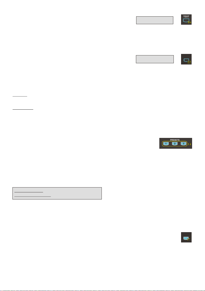
IMAGE TURN MODE (for higher resolution)
Working surface:
Normal mode:
A
Only 50% of the
pixels are used to
pick up the document
Image turn mode:
90% of the pixels
A
are used to pick
up the document
Just place your document (or other vertical object)º on the working surface horizontally and zoom in on it
completely, so that about 90% of the pixels of the built-in camera are used to pick up the document.
Then press the IMAGE TURN-key (#15) one time. The Visualizer turns the picture electronically 90
and outputs it the right way up with a much higher resolution than in normal mode. The left and right
margins are black.
The IMAGE TURN-key (#15) can also be used to rotate the image 90, 180 and 270 degrees.
Each time this key is pressed, the image rotates 90 degrees.
Output picture:
A
A
Picking up a complete vertical (portrait) document or
A4 page has always been a critical issue for a
Visualizer, because the image is always picked up in
a horizontal (landscape) format.
The camera could only use 50% of its pixels to pick
up a vertical (portrait) page. WolfVision's Image turn
mode solves this problem.
6
TEXT ENHANCEMENT
For improving the readability of text, sketches and x-rays press the TEXT-key (#16). This mode
enhances the contrast of the picture. Please note that in this mode the colors are darker than usual. To
switch off the text enhancement mode press the TEXT-key again.
While the text mode is activated the TEXT-key on the control panel is illuminated red.
IMPORTANT
WHITE BALANCE ADJUSTMENT
Each time the lighting condition changes, the user should adjust the white balance of the Visualizer's
camera, in order to optimize the color reproduction. The Visualizer's top- and bottom-light have the
same color temperature so normally a new white balance adjustment is not necessary when changing
from one light to the other, but if there is also room light or sun light shining on the working surface,
the white balance should be adjusted.
Top light: First, zoom in on a white object (for example a white paper) until there is only white on the
screen. Then press the WHITE-key (#22).
Bottom light: Turn on the bottom light with the LIGHT-key (#21). Remove everything from the working
surface. Zoom to the smallest picture. Then press the WHITE-key (#22).
You can adjust the white balance either for the top or for the bottom light and it works well with both
lights. When the white balance adjustment is finished successfully the message "WHITE OK" appears
on the monitor after a few seconds. The new white balance is stored automatically and is preserved
even if the power supply is interrupted.
IMPORTANT
WHITE
PRESET FUNCTION
WolfVision Visualizers offer the possibility of programming three presets for the functions: Zoom,
Focus, Iris, Light, Text, Macro, White Balance, Mirror position*, Positive/Negative and Black/White.
They can be recalled by pressing one of the three PRESET-keys (#14) on the control panel or the
remote control.
.
This function is very useful for example if a user requires one preset for papers on the working surface,
one for working with slides (bottom light) and one for an object placed in front of the unit. During his
presentation the user just has to press one of the PRESET-keys when he changes from one object to
Quickly pressing: Recalling a preset
More than 2 seconds: Saving a new preset
* You can select in the unit's on-screen menu if
the mirror position should be stored in a
preset or not (see page 9). Default is: YES.
For programming a preset just adjust every function as required and then keep one of the PRESET
keys pressed for more than 2 seconds. The on-screen menu tells you when the preset is stored.
When the presets are stored as mentioned above, all current settings like zoom-, focus- or mirrorposition are stored. Contrary to this, a user also has the opportunity to assign only specific functions
such as "Freeze", "Iris open/close", "Negative", "Negative/Blue", "Black/White" etc. to a PRESET-key.
This can be done in the on-screen menu of the Visualizer (see page 9).
FREEZE
The current image can be frozen by pressing the FREEZE-key 7 .
The FREEZE-key is red illuminated if the freeze function is activated. The FREEZE-key also works as
image memory key if pressed for 2 seconds (see page 8).
The behavior of the FREEZE-key can be changed in the on-screen menu (see page 9).
7
(#1 )
FREEZE
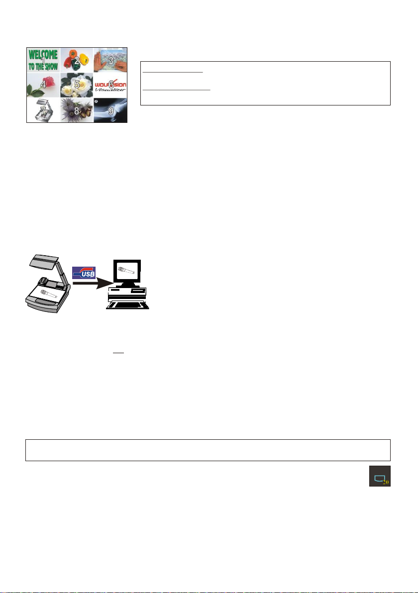
9-IMAGE MEMORY
You can store 9 images and recall them by just pressing one of the
numerical keys (#31) on the infrared remote control:
Storing an image: Press one of the MEMORY-keys (#31)
for more than 2 seconds
Recalling an image: Press one of the MEMORY-keys (#31)
quickly
By pressing the ALL-key (#30) a split image with all 9 pictures of the
Split image of 9 picture memory
memory can be displayed.
When pressing the ALL-key (#30) for 4 seconds, a menu appears on the screen asking if you would
like to erase all stored pictures (black picture) or if you would like to fill the memory with “snapshots”.
When choosing “snapshot” the Visualizer stores a new image every second until the 9 memory
locations are full.
The Visualizer is equipped with a memory backup battery. It stores the pictures in the memory when the
power supply is disconnected for up to 4 weeks. Images can also be stored by pressing the FREEZEkey (#17) for 2 seconds. The image will be stored in the next available memory (1-9). If the memory is
full, an on-screen message will appear.
The functional settings of the memory feature can be changed in the on-screen menu (see page 9).
USB-PORT
The USB 2.0 port of the Visualizer can be used to capture and
transfer Visualizer images onto a computer.
HI-SPEED
CERTIFIED
TM
In this way the Visualizer can be used as a scanner for
3-dimensional objects for your computer. Just connect the USB
port (#37) of the Visualizer to the USB port of your computer, using
the supplied USB cable. The software is fully Twain compatible.
The USB 2.0 output of the Visualizer is fully USB 1.1 compatible
(less speed with USB 1.1).
The WolfVision USB-software can be found on the supplied CD-ROM. Please check our Internet
homepage at: www.wolfvision.com/support if an update of this software is available as a freedownload. The software works under Windows 98/ME/2000/XP and MAC OS10 (or later).
Windows 95 and NT will not work, because they do not support USB.
ETHERNET / LAN
The LAN connection (10BASE-T/100BASE-TX) can be used for controlling the Visualizer over a
computer network, image transfers and firmware updates.
The following protocols are supported: TCP/IP, ICMP and ARP.
Standard settings (changeable): IP-address and Subnet-mask from DHCP-Server
Image Transfer Resolution: Still Image: 1024x768 (or 512x384), Live Image: 160x120
Please check the special ETHERNET/LAN manual on our homepage at:
www.wolfvision.com/support.
EXTERNAL INPUT / SCALER
A Computer can be connected to the External RGB input (#41) of the Visualizer.
By pressing the EXT/INT-key (#20), you can switch between the Visualizer image and the image of the
external input to displayed to the audience.
The extern mode can also be used for only one output. The behavior can be changed in the on-screen
menu (see page 9). The Visualizer has a built-in scaler (A/D-converter) in order to digitize the analog
RGB signal from the computer and output it on all outputs in the selected format (allowed signals: from
VGA to SXGA/75Hz). As the built-in scaler allows the image from the external input to be output on the
PAL/NTSC video outputs, the Visualizer can also be used as a computer to video image converter.
:Supported Browsers are Internet Explorer, Netscape Navigator and Mozilla.
EXT/INT
8

ON-SCREEN MENU / ON-SCREEN HELP
For standard use of the WolfVision Visualizer it is not necessary to enter the on-screen menu
of the Visualizer and change settings. Inexperienced users should not make any adjustments here.
To enter the on-screen menu press the MENU-key (#23) for one second. Settings of the Visualizer's
basic functions and the built-in camera can be made here using the 4 select keys (#26, = the numerical
keys with red arrows on the remote control - #31).
Please note that some basic settings in the menu can only be changed if you set the menu item
"Format protect" to "OFF" first.
If more information on a function in the on-screen menu is required just set the cursor in the respective
line and press the HELP key (#25, or the Number 5 key #31, this key has a double function). A detailed
description of this function appears on the screen. If you want to reset the selected item to the default
setting, just press the HELP key (#25, or Number 5 key #31) for 2 seconds!
The functions of the on-screen menu are not described in detail in this user manual as the help menu is
an integrated part of the Visualizer's software (firmware). The information you see on your screen
always belongs to the current Visualizer firmware.
SWITCHING to NEGATIVE, NEGATIVE/BLUE and BLACK/WHITE
The output image of the Visualizers can be switched from positive to negative in the on-screen menu.
In addition, the background of a negative image can be switched to blue for better readability of text.
You can also switch between color and black/white in the on-screen menu.
TIP: If you often switch to negative, negative/blue or black/white images you can assign this function to
one of the PRESET-keys (#14) in the on-screen menu (see page 7).
CHANGING THE STANDARD CONTRAST (color) SETTINGS
If the picture or the colors on your screen appear to be too dark, you can lower the overall contrast of
the picture in the "Color settings" menu of the on-screen menu. The settings can be made separately
for the normal mode and the text-mode.
AUTO POWER OFF
In the "Power control" settings in the on-screen menu you can select that the Visualizer will be
automatically switched off, if not used for a certain amount of time.
RESET of ON-SCREEN MENU SETTINGS
All settings in the on-screen menu can be set back to the factory defaults. "Reset" is one item in the onscreen menu. In case you can not read the menu on a screen you can also set the unit back to the
factory defaults by simultaneously pressing the EXT/INT-keys (#20) and the MENU-key (#23) on the
unit.
If you only want to reset a currently selected item to the default setting, press the Help-key (#25, or
Number 5-key on the remote control #31) for 2 seconds!
FIRMWARE UPGRADES
The software (firmware) of your Visualizer (including the o ) can easily be upgraded to
the latest version.
First download the latest firmware and WolfVision's firmware update utility program from Wolfvision's
internet homepage at www.wolfvision.com/support.
Then connect the Visualizer to your computer and run the firmware update utility program. More details
on the firmware updates can be found on WolfVision's internet homepage.
The firmware update can be done via USB, Ethernet (LAN) or RS232.
n-screen HELP
9
INFRARED REMOTE CONTROL
Please note that an infrared remote control can only be used up to a certain distance from the unit.
Objects situated between the Visualizer and the infrared remote control, and weak batteries, interfere
with the reception. If the Visualizer can only be controlled from a close distance, or if it cannot be
controlled at all with the infrared remote control, you may have to change the batteries. Open the cover
on the back of the remote control by hand and replace the two 1.5 V AA batteries with new ones.
Check the polarity of the batteries!
If a user wants to work with a number of WolfVision Visualizers
ZOOM MIRROR
LASER
PRESETS
IMAGE TURN
A
2 3
1
A
FOCUS IRIS
AF
EXT / INT
LIGHT
ALLTEXT
MEMORY
1
3
2
HELP
5
6
4
7
9
8
POWER
MENU
front back (open)
-
X
+
simultaneously, each unit can be set to a different infrared code,
so up to 4 units can be controlled individually with their remote controls.
To change the infrared codes on the Visualizer, enter the
screen menu, by pressing the menu-key (#23) for one second, go
"Misc. Settings" and set the "IR Code" to A, B, C or D (code A is
to
default). To change the infrared code on the remote control,
+
simultaneously press PRESET 1, PRESET 2 and ZOOM TELE
(#13) - each time this key combination is used, the code switches from A
X
to B, C, D ... A ...etc. For resetting the remote control to code A
-
simultaneously p .
ress PRESET 1, PRESET 2 and ZOOM WIDE
(#14)
The LED shows the selected code (it flashes one-time for code A,
two-times for code B, three-times for code C and four-times for code D)
on-
AUTOMATIC LAMP CHANGER
The Visualizer is fitted with an automatic lamp changer. If one lamp fails, there is no need
to replace it immediately, as the automatic lamp changer automatically switches to the second (spare)
lamp. When the unit changes lamps there is an on-screen message saying: "Changing lamp".
When switching on the unit the Visualizer checks if both lamps are working. If one lamp fails there will
be an on screen message for a couple of seconds displaying "Lamp x blown". This prevents a user
from forgetting to change a defective lamp.
If a lamp is not fully defective but worn out and as a result the light output is quite weak, you can switch
manually to the second lamp by pressing the LIGHT-key (#21) for 2 seconds.
EXCHANGING LAMPS
1. Turn the unit off (#28) and disconnect the
power cord!
2. Remove the bottom light (#9) by pulling the
two spring catches (situated left and right of
Lamp exchange
cover (#11)
the control panel) to the front and lift up the
bottom light plate.
3. Remove the lamp exchange cover (#11)
by turning anti-clockwise and lift it.
4. Change the lamp (or both lamps)
Before changing the lamp allow it to cool or use a cloth to avoid burning a finger! When pressing a new
lamp into the socket use a cloth to prevent fingerprints on the lamp!
Only use 12 V/100 W halogen lamps (socket: GY 6,35), type: Osram HLX 64623,
Ansi EVA, LIF M/28 NAED 54052. These are relatively inexpensive standard OHP lamps.
THERMOSTAT
If the unit gets too hot (improper ventilation or air extraction) a built in thermostat will switch off the light
of the Visualizer. Verify that proper ventilation and air extraction is available and allow the unit to cool.
10
 Loading...