

WolfVision VZ-37 Instructions Manual
INSTRUCTIONS
INSTRUCTIONS
ENGLISH
R
Check out our INTERNET HOMEPAGE for additional technical information: http://www.wolfvision.com
VZ-17 / VZ-37
VZ-17 / VZ-37
FCC
This equipment has been tested and found to comply with the limits for a Class A digital device, pursuant to Part
15 of the FCC Rules. These limits are designed to provide reasonable protection against harmful interference when
the equipment is operated in a commercial environment. This equipment generates, uses, and can radiate radio
frequency energy and, if not installed and used in accordance with the instruction manual, may cause harmful
interference to radio communications. Operation of this equipment in a residential area is likely to cause harmful
interference in which case the user will be required to correct the interference at his own expense.
This product is built according to Directive EMC and to Directive electrical equipment.
ETL
LASER RADIATION
DO NOT STARE INTO BEAM
CLASS 2 LASER PRODUCT
OUTPUT POWER <1mW
WAVELENGTH 650nm
EN 60825-1 March 1997
AVOID EXPOSURE -
Laser radiation is emitted
from this aperture.
FDA accession number:
9912688-00
This device complies with
21 CFR 1040.10 and 1040.11
LASER RADIATION - DO NOT
STARE INTO BEAM
650nm, P<1mW, tp<6ms
CLASS II LASER PRODUCT
Vorsichtmassnahmen
Precautions for built-in laser center marker:
Vorsichtsmaßregeln für den eingebauten Laserpositionierpunkt:
Risk of electric shock
Dangerous voltage inside
WARNING!
Elektroschockrisiko -
Gefährliche Netzspannung
im Gerätinneren
ACHTUNG!
DAS GERÄT NUR MIT DER AUF DEM TYPENSCHILD
ANGEGEBENEN NETZSPANNUNG VERWENDEN!
DAS GERÄT VOR FEUCHTIGKEIT SCHÜTZEN!
DAS GERÄT NIEMALS AM ABTASTKOPF BZW. ARM
AUFHEBEN ODER BEWEGEN!
BEIM TRANSPORT DAS GERÄT VOR ERSCHÜTTERUNG
SCHÜTZEN!
Es ist darauf zu achten, dass eine ausreichende
Luftzirkulation zur Kühlung des Gerätes möglich ist
(Lüftungsschlitze links und rechts unbedingt freihalten)!
Bei jeder Art von Störungsanzeichen (abnormale
Geräusche, Geruch, Rauchentwicklung etc.) das Gerät
abschalten. Setzen Sie sich bitte in solchen Fällen
umgehend mit Ihrem Visualizer-Händler in Verbindung!
Niemals ein beschädigtes Netzkabel verwenden.
Andernfalls kann es zu Kurzschlüssen und zu
elektrischen Schlägen kommen!
Am Gerät keinerlei Umbauten vornehmen und das Gerät
niemals ohne Gehäusedeckel in Betrieb nehmen!
Keine entflammbaren oder metallischen Gegenstände
oder Flüssigkeiten in das Geräteinnere dringen lassen!
Flüssigkeiten oder nasse Gegenstände nicht auf die
Arbeitsplatte, sondern vor oder hinter das Gerät stellen.
Bei Arbeiten mit nassen Händen gegebenenfalls das
Bedienfeld mit einer Folie abdecken!
Das Gerät nicht im Bereich von starken Magnetfeldern
und elektrischen Feldern verwenden.
Das Gerät nicht im Wirkungsbereich von
Röntgenstrahlung betreiben. Dadurch können Teile der
Kamera beschädigt werden.
Wird das Gerät längere Zeit nicht benutzt,
Netzhauptschalter (34) abschalten!
.
.
.
.
.
.
.
.
.
.
.
Angeführte Vorsichtsmassregeln unbedingt beachten:
Precautions
USE THIS MACHINE ONLY WITH THE CORRECT
VOLTAGE AS SHOWN ON THE TYPE LABEL !
DO NOT EXPOSE THE UNIT TO EXTREME HEAT OR
MOISTURE !
DO NOT CARRY THE VISUALIZER HOLDING IT ONLY BY
ITS MIRROR ARM (#1) !
DURING TRANSPORTATION PROTECT THE UNIT FROM
EXCESSIVE SHOCKS !
Make sure that sufficient air circulation for cooling the
unit is possible (ventilation slots on the left and right side
of the unit)
If there is any abnormality (abnormal noise, smell, smoke
etc.) turn the power off immediately and contact your
Visualizer dealer!
Do not use a damaged power cord.
This may cause short circuits or electrical shocks!
Do not modify the Visualizer or operate it without the
cover panel firmly in place, to prevent danger!
Do not expose the Visualizer to water, metallic objects or
any flammable material. Do not place liquids or wet
objects on the working surface! Put them in front of or
behind the unit and use it as a camera. If you work with
wet hands, cover the remote control with plastic wrap!
Avoid installing the Visualizer in environments where
there is radiation.
Avoid installing the Visualizer in locations exposed to
strong magnetic fields or electrical currents.
This could cause monitor image distortion or damage to
the CCD camera.
If the Visualizer is not used for a long time turn off the
main power switch (#34)!
.
.
.
.
.
.
.
.
.
.
.
Please follow these precautions:

Contents:
ENGLISH
page 2
page 5 IMPORTANT
page 6
page 6
page 6
page 7
page 7
page 7
page 7
page 8
page 8
page 8
page 9
page 9
page 9
page 9
page 9
page 10 IMPORTANT
page 10
page 11
page 11
page 11
page 11
page 12
page 12 IMPORTANT
page 12 IMPORTANT
page 13 IMPORTANT
page 15
page 16
page 17+18
page 13
page 13
page 14
page 14
page 14
page 14
See on-screen HELP menu of the Visualizers
Printed in Austria Design and specifications subject to change! January 2001
Contacts:
Internet Homepage: http://www.wolfvision.com / Technical support by E-mail: support@wolfvision.com
Manufacturer:
Wolf Vision GmbH
Vlbg. Wirtschaftspark
A-6840 Götzis / AUSTRIA
Phone: ++43-5523-52250
Fax: ++43-5523-52249
E-Mail: wolfvision@wolfvision.com
American distribution:
655 Sky Way, Suite 119
San Carlos, CA 94070 / USA
Phone: (650)802-0786 or 1-800-356WOLF
Fax: (650)802-0788
E-Mail: wolfvision.usa@wolfvision.com
Wolf Vision Inc.
Australian distribution:
WolfVision Pty Ltd.
P.O.Box 59, West Lindfield
NSW 2070, Australia
Phone: (02) 9410 3388
Fax: (02) 9410 3388
E-mail: wolfvision.australia@wolfvision.com
Canadian distribution:
WolfVision Canada Inc.
140 Route 202, Noyan QC JOJ 1B0
Phone: (450)294-9999
Tollfree: 1-877-513-2002
Fax: (450)294-2228
E-Mail: wolfvision.canada@wolfvision.com
Asian distribution:
WolfVision Rep office
27 Woodlands Ind. Park E1
#01-04 Hiang Kie Ind. Bldg. IV
Singapore 757718
Phone: ++65 - 366 9288
Fax: ++65 - 366 9280
E-mail:
wolfasia@mbox2.singnet.com.sg
The professional WolfVision Visualizer system was developed and designed by WolfVision in Austria.
The units are "MADE IN AUSTRIA", Patents (examples): US 5027219, FRG 3833908, CH 678576
Precautions
Connections
Switchable outputs
How the Visualizer works
Basic preparations
Working on the working surface
Focusing
Working outside the working surface
Synchronized Light field
Bottom light / Laser center marker
Working with transparencies
Macro mode
Preset function
Reset function / Power-on preset
Autoiris / manual iris
Video recording
Connecting a computer or video conferencing system
Text enhancement
Special adjustment of LCD- or DLP projectors
Infrared remote control
Automatic lamp changer
Exchanging lamps
Thermostat
Exchanging a fuse
Mirror cleaning
White balance adjustment
Transportation
Dimensions
Technical data
Troubleshooting
Additional chapters for experienced:
On-screen menu / Camera menu
Reset of on-screen menu settings / menu-presets
Positve / Negative switching
Software upgrades
External synchronization
Control Connectors (Serial and parallel)
Detailed settings of the on-screen menu

CONTROL PANEL
4
ATTENTION: Check which Visualizer model you have!
#1 Arm
#2 Base mirror
#3 Top mirror
#4 Control pannel
#5 Synchronized lightfield (Top light)
#6 Remote Control
#7 Ventilation
#8 Air extraction
#9 Working surface with built-in
Bottom light (removable)
#10 Connectors (on the back)
#11 Lamp exchange cover
(under the removable bottom light)
This is a combined user manual for the professional WolfVision Visualizer models: VZ-17 and
VZ-37.
It is noted in the headline if the following chapter applies just to one of these models.
Therefore it is important that you check which Visualizer model you have!
#12 Upper MIRROR up and down (for scrolling)
(C
#13 ZOOM keys (enlargement)
#14 Three user programmable PRESETS
(stored by pressing one of the keys for 4
seconds, recalled by pressing quickly)
#16 TEXT Enhancement key
(improves the contrast for better readability)
#17 IMAGE (switches the output image on and off)
#18 MACRO (for bigger enlargements - see page 8)
#19 Manual FOCUS adjustment (see page 7)
#20 RESET (activates the Power-on preset)
an also be moved by hand! This does not
cause any harm to the motor of this mirror!)
#21 LIGHT (switches between "Top light",
"Bottom light" and "Light off")
#22 Manual WHITE BALANCE adjustment
(see page 12)
#23 MENU (activates the on-screen menu
- see page 13)
#24 Manual IRIS (brighter and darker picture)
#25 HELP (activates the on-screen help for
the on-screen menu - This key is only
visible after pressing MENU #23)
#26 SELECT keys for on-screen menu (only
visible after pressing MENU #23)
#27 Motorized ARM up and down
#28 (Standby) POWER on and off
#29 Power LED light (red=off, green=on)

CHOOSING THE RIGHT VIDEO OUTPUT
IMPORTANT
Y/C output (S-VHS - #37 and #38)
RGBS output (#41)
VZ-37:
VZ-17:
On the VZ-17 the RGBS-signal is actually only a converted Y/C-signal. (As the VZ-17 has a 1-chip camera and no 1chip camera has a true RGBS output). This output is intended for units which do not have Y/C-input. The quality is
better than composite video but not better than Y/C !
Most RGB-monitors or projectors use a separate Sync connection. For units without a separate Sync connection
the Sync Signal can be added to the Green-signal.
The "Sync on green" function can be switched on and off by simultaneously pressing the following three keys:
IMAGE (#17), FOCUS near (#19), FOCUS far (#19). The factory setting is "Sync on green - off".
If "Sync on green" is switched on, make sure that no separate sync cable is connected - the result
could be a picture with too much green!
Component output (#41 - VZ-37 only)
The RGBS output of the VZ-37 can be switched to Component output (YUV) by simultaneously pressing the following
three keys: IMAGE (#17), IRIS dark (#24), IRIS bright (#24).
The connections are the following: Red=R-Y, Green=Y, Blue=B-Y
Composite video output (#32)
Only use this output if the display device does not have Y/C or RGBS input. This is the oldest standard with the lowest
bandwidth the quality is not as good as with the other outputs.
Preview video output (#31)
This is a composite video output for a control monitor. It's the only output that is not switched off, when the IMAGE key
(#17) is used. Do not use this output for the audience's monitor or projector!
For live image projection it is recommended to use the Y/C output as the signal passes a sharpness enhancer. It even
looks better than with the RGBS output of the VZ-37. Only the Component output (YUV) of the VZ-37 offers a better
quality than the Y/C-output.
The VZ-37 offers a true RGBS-signal. Red, Green and Blue are directly connected to each of the 3 chips of the
camera. As a result this output offers the best color reproduction. This signal is also recommended for image
processing as it is the original (unprocessed) signal.
(On the VZ-37 this output can be switched to YUV - see below)
5
31
#31 PREVIEW video output (details see below)
#32 Composite VIDEO output (details see below)
#33 External SYNC INput (Genlock)
#34 Main POWER switch
#35 FUSE (see page 12)
#36 POWER connection
#37 Y/C (S-VHS) output (details see below)
4-pin connector
#38 Y/C (S-VHS) output (details see below)
2 x BNC connectors
#39 SERIAL port for external remote controlling
#40 PARALLEL port for external remote controlling
#41 RGBS output (can be switched to YUV on
VZ-37 - details see below)
HOW THE VISUALIZER WORKS
All outputs of the WolfVision Visualizers - except the Preview output (#31 or #43) - are switchable. Use the
IMAGE key (#17) to switch the signal supplied from these outputs on and off. Independently an image is always output
by the Preview output (#31 or #43). This output can be used for a control monitor.
A constant sync signal is supplied to all switchable outputs (even in the image off mode) eliminating monitor image
distortions when switching.
When the output signal is switched off the IMAGE key on the control panel is illuminated red.
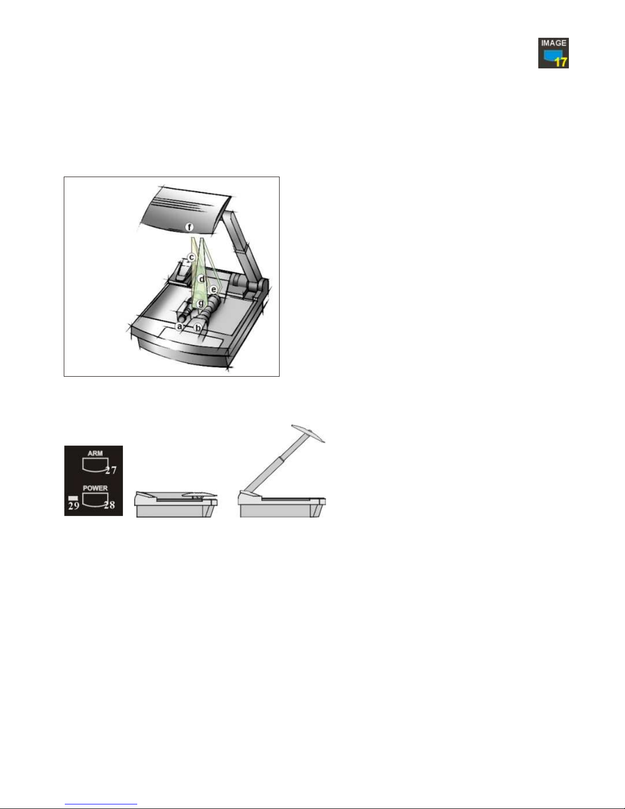
How it works:
A light projector (a) inside the unit projects a
lightfield (g) the same size as the pick-up area
of the built-in camera via the base mirror (e)
and the top mirror (f) onto the working
surface. The image is recorded by the camera
(b) using the same path.
The lenses of the light projector (a) and the
camera (b) are synchronized. Thus the size of
the light field on the working surface changes
when the user changes the zoom range of the
camera.
This scanning and illumination system is a
worldwide patent from WolfVision.
1. Connect the power cable to the unit (#36) and plug it in.
2. Connect a control monitor (if required) to the Preview output (#31 or #43).
3. Connect a large viewing monitor or a projector to one of the outputs of the Visualizer.
For choosing the right output please read the previous pages!
4. Turn the main power switch (#34, on the back of the unit) to "I". The red power indicator (#29) on the control
panel indicates that power is supplied.
5. If the arm is folded down press the ARM key (#27) on the control panel, then the arm comes up automatically.
6. Press the POWER key (#28) on the control panel. The Visualizer now runs the "power-on preset" (=automatic
focusing of an A5 format on the working surface) during which the green LED light (#30) is flashing. As soon as
the green LED light stays illuminated you can start working with the Visualizer.
(The behaviour of the unit once that power is supplied to the unit or after the POWER key is pressed can be
changed in the unit's menu - see page 13 and on-screen help menu)
SWITCHABLE OUTPUTS
6
BASIC PREPARATIONS
a) light projector
b) camera
c) light path
d) image path
e) base mirror
f) top mirror
g) pickup area /
synchronized
lightfield
 Loading...