


White Rodgers 36C03U-433, 36C03U-333, 36C03-400, 36C03-433, 36C03-300 Installation Instructions
...36C03, 36C03A, 36C03U & 36C10
Standing/Continuous Pilot Combination Gas Valve
INSTALLATION INSTRUCTIONS
FAILURE TO READ AND FOLLOW ALL INSTRUCTIONS CAREFULLY BEFORE INSTALLING OR OPERATING THIS CONTROL COULD CAUSE PERSONAL INJURY AND/OR PROPERTY DAMAGE.
DESCRIPTION
The 36C03 and 36C10 series valves are designed to meet requirements for use on standing continuous pilot systems. 36C03 combination models include a pressure regulator, 100% shut-offauto- matic pilot, and main operator. 36C10 models do not have a pressure regulator.
ECO
Terminals
ON
PILOT
OFF
ON
PILOT
FOF
36C Inst |
Voltage |
# of |
Open |
Standing |
Intermittent Pilot |
HSI |
DSI |
|
Stages |
Characteristics |
Pilot |
Proven Pilot |
|||||
|
|
|
|
|||||
36C03/36C10 |
24V |
1 |
Fast |
Yes |
No |
No |
No |
|
36C03U |
750mV |
1 |
Fast |
Yes |
No |
No |
No |
|
36C03A |
120V |
1 |
Fast |
Yes |
No |
No |
No |
SPECIFICATIONS
PIPE SIZES/CAPACITIES
|
Capacity (BTU/hr) at |
Range of Regulation |
||
|
1" pressure drop across valve |
Excluding 36C10 Non-Regulated |
||
|
Nat.Gas |
LPGas |
AGAStd.Nat.Gas |
LPGas |
Pipe Size |
(1000BTU/cu.ft.,64 |
(2500BTU/cu.ft., |
0.64 Sp.Gr. |
1.53 Sp.Gr. |
(inches) |
Sp.Gr.) |
1.53 Sp.Gr.) |
(1,000 BTU/cu.ft.) |
(2,500 BTU/cu.ft.) |
1/2" x 3/8" |
100,000 |
162,000 |
15,000 - 100,000 |
15,000 - 162,000 |
1/2" x 1/2" |
230,000 |
372,600 |
30,000 - 290,000 |
30,000 - 469,000 |
1/2" x 3/4" |
230,000 |
372,600 |
30,000 - 290,000 |
30,000 - 469,000 |
3/4" x 3/4" |
280,000 |
453,600 |
50,000 - 400,000 |
50,000 - 648,000 |
PRESSURE REGULATOR ADJUSTMENT RANGE EXCLUDING 36C10 NON-REGULATED
Gas Type |
Single Stage |
Natural Gas |
2.5–5.0 |
LP Gas |
7.5–12.0 |
Pilot Gas Outlet:
Located at outlet end of the valve Type of Gas: Suitable for all domestic heating
gases
Ambient Temperature: -40º to 175ºF Pressure Rating: 14" W.C. (1/2 PSI) Max
Voltage/Current: 36C03U – 750mV 36C03/36C10 – 24V/0.23A 36C03A – 120V/0.035A
Parts and Accessories:
Conversion Kit
•F92-0659 Nat. to LP Gas (7.5" to 12.0" W.C.)
•F92-0737 Nat. to LP Gas (Non-regulated)
•F69-0727 1/4" brasscompressionfittingforpilot line connection
Thermocouple (24V & 120V types): |
|
Use W-R Type H06 |
|
Pilot Generator (.750 volt types): |
|
Use W-R Type G01A-32 |
|
CONTENTS |
|
Description ........................................................................... |
1 |
Specifications ....................................................................... |
1 |
Precautions............................................................................ |
2 |
Installation............................................................................. |
3 |
System Wiring |
|
Adjustment ........................................................................... |
5 |
Pressure Regulator Adjustment |
|
Lighting Instructions............................................................. |
6 |
Contents French......................................................................... |
9 |
Contents Spanish..................................................................... |
17 |
www.white-rodgers.com |
PART NO. 37-7349B |
Replaces 37-7349A |
|
www.emersonclimate.com |
1429 |
SPECIFICATIONS
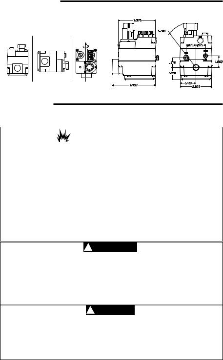
MOUNTING POSITIONS
Upright, 90 from upright or vertical
UPRIGHT |
INLET BOSS |
UP OR DOWN |
|
|
LEFT OR RIGHT |
ON
FOF
NOTE: Control shown may not be identical to replacement control |
|
Figure 1. Gas Valve Mounting Positions |
Figure 2. Valve Dimensions |
PRECAUTIONS
DO NOT BEGIN INSTALLATION UNTIL YOU READ THE FOLLOWING PRECAUTIONS.
|
! WARNING |
|
Ifyoudonotfollowtheseinstructionsexactly,afireorexplosion |
|
|
mayresult,causingpropertydamage,personalinjuryorlossoflife. |
|
|
|
|
|
1.Failure to turn off electric or main gas supply to heating system could cause personal injuryand/orpropertydamagebyshock,gas suffocation,fire,and/orexplosion.
2.Do not use this control on circuits exceeding specifiedvoltage. Highervoltage will damagethecontrolandmaycauseshockorfire hazard.
3.NEVERUSEFLAMEORANYKINDOFSPARK TOCHECKFORGASLEAKS–COULDCAUSE FIRE AND/OR EXPLOSION.
4.DO NOT USE WIRE JUMPER on pilot systems, such as standing pilot, proven pilot, orspark-to-pilotignition–afireand/orexplo- sion may result.
5.DonotuseacontrolsetfornaturalgaswithLP gas,oracontrolsetforLPgaswithnaturalgas.
Personal injury and/or property damage, gas suffocation,fire,and/orexplosionmayresult.
6.Do not use a gas valve which appears to be damaged. A damaged valve may cause personal injury and/or property damage due to shock, gas suffocation, fire and/or explosion. Contact supplier to replace any valve that appears to have been damaged.
7.Donotuseagasvalvethathasbeenindirect contactwithwater.Waterenteringgasvalve may result in concealed internal damage to gas valve. Personal injury and/or property damage,gassuffocation,fireand/orexplosion may result.
!WARNING
Properly install gas piping to control.
•Donotremoveprotectiveinletoroutletcapsuntilreadytoconnectsupplypipetogasvalve.
•Usenewsupplypipe,properlythreaded,reamed,de-burred,andcleaned.
•Usebackupwrench,appliedonlytoprovidedwrenchflatsoninletboss,whentighteningthe supply pipe. Do not grip bracket, solenoid or any other part of control.
•Donotover-tightenpipetocontrol(50 ft-lbs max.)
•Alwaysinstallsedimenttrapinthegassupplylinetopreventcontaminationofgasvalve. Failuretoinstallproperlycancausegasleakageresultingininjuryduetofireorexplosion.
!CAUTION
1.Do not short out terminals on gas valve or primary control to test.Short or incorrect wiring can cause equipment damage, property damage, and/or personal injury.
2.Thiscontrolisnotintendedforuseinlocationswhereitmaycomeindirectcontactwithwater. Suitableprotectionmustbeprovidedtoshieldthecontrolfromexposuretowater(dripping, spraying, rain, etc.).
3.Cleangaspipingofcontaminants,cuttingfluid,orotherchemicalswhichmightreactharmfullywiththegasvalvecomponentsbeforeinstall.
2
MAIN PIPING CONNECTIONS
NOTE
Allpipingmustcomplywithlocalcodes,ordinances, and/or national fuel gas codes.
1.Turnoffelectricalpowertothesystematthefuse boxorcircuitbreaker.Alsoturnoffthemaingas supply.
2.If replacing an existing valve, disconnect all plumbing and electrical connections from the old control.
3.The control may be installed in any orientation except upside down (see fig. 1). The arrow on the valve indicates the direction of gas flow through the control.
4.You should use new pipe that is properly chamfered, reamed, and free of burrs and chips. If you are using old pipe, be sure it is clean and free of rust, scale, burrs, chips, and old pipe joint compound.
INSTALLATION
5.Applypipejointcompound(pipedope)orteflon tape that is approved for all gases, only to the male threads of the pipe joints. DO NOT apply compoundorteflontapetothefirsttwothreads (seefig.3 for typical piping connections).
6.Ifyouareusingaviseoropen-endwrenchtohold the valve while installing piping, do not tighten excessively, as this may damage the valve.
7.If additional clearance for the gas cock knob is required when installing the new valve in an existing system, rotate the knob to the position between ON and OFF. Depress the knob while turning the valve. The knob will depress only while in this position.
8.See SYSTEM WIRING when making electrical connections.After all gas and electrical connections are completed, turn gas on and check for gas leaks with leak detection solution or soap suds. Bubbles forming indicate a leak. SHUT
OFFGASAND FIXALL LEAKS IMMEDIATELY.
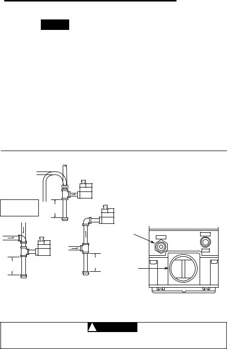
Drop |
PILOT GAS CONNECTION |
|
|
|
Horizontal |
|
Installthefittingintothepilotgasoutlet(see |
||
|
|
|
|
|
|
fig.4),turninguntilfinger-tight.Insertclean, |
|
|
|
|
|
|
|
deburredtubingallthewaythroughthefitting. |
|
|
|
|
|
|
|
While holding the tubing securely, slowly tighten |
|
|
|
|
|
Gas Valve |
fittinguntilyoufeelaslight“give”.Tightenthe |
||
NOTE: |
|
|
Riser |
fittinganadditional1-1/2 turns. |
|||
|
|
3 in. |
|
||||
Always Include |
|
minimum |
|
Refer to page 5 for pilot gas adjustment information. |
|||
A Drip Leg In Piping |
|
||||||
|
|
|
|
|
|||
Drop |
|
|
Tubing Gas |
|
|
|
|
|
|
|
|
Gas Valve |
|
|
|
|
|
|
|
Supply |
|
|
|
Horizontal |
|
|
|
Riser |
Pilot gas |
|
|
|
|
|
|
PRESS |
|||
|
|
|
|
|
outlet |
||
|
|
|
|
|
|
PILOT |
|
|
|
|
|
|
|
|
TAP |
|
|
Gas Valve |
3 in. |
|
|
||
3 in. |
|
|
|
|
|
|
|
|
|
|
|
minimum |
Gas outlet |
|
|
minimum |
Piped Gas |
Piped Gas |
|
|
|||
|
|
|
|
||||
|
Supply |
|
|
|
|||
|
Supply |
|
|
|
|||
|
|
|
|
|
|||
Figure 3. Typical gas valve piping |
|
|
|||||
|
|
|
|
|
|
|
Figure 4.Gasvalvesideview |
! CAUTION
To prevent electrical shock and/or equipment damage, disconnect electrical power to system at main fuse or circuit breaker box until installation is complete.
3

SYSTEM WIRING
NOTE
Allwiringshouldbeinstalledinaccordancewithlocalandnationalelectricalcodesandordinances.
Always check that the electrical power supply used agrees with the voltage and frequency shown on the gas control.
Thetypicalwiringdiagramshowsonlytheterminalidentificationandwiringhookup.Alwaysreferto wiring instructions provided by Equipment Manufacturer for system hookup operation.
Electrical Cut Out (E.C.O.) Switch or
Supplementary Limit in appliance
Jumper
NOTE: If appliance does not have E.C.O. Switch
or supplementary limit, jumper E.C.O. terminals
ECO Terminals (2)
ON
T
PILO
OFF
TH, TH-TR to Thermostat
Power Unit
TH |
TR |
TH TR |
|
PILOT |
TH-TR, TR to Transformer |
ADJ. |
W |
R |
24 VAC |
Line |
Hot |
|
|
|
|
|
Thermostat |
Transformer |
|
||
Figure 5. Wiring for 36C03(24 VAC)
For appliances with an Electrical Cut Out (E.C.O.) device or supplementary high limit switch, connect black wire from power unit to one side of the switch. Attach the other side of the switch to TH-PG.
ON
T
PILO
OFF
For appliances without an Electrical Cut Out (E.C.O.) device or supplementary high limit switch, connect black wire from power unit to TH-PG.
PG
THPG
PILOT
ADJ.
|
TH, TH-PG to Thermostat |
TH-PG, PG to Pilot Generator |
|
TH |
PG |
|
|
|
W |
R |
Pilot |
|
Generator |
||
|
|
|
|
Thermostat
Figure 6. Wiring for 36C03U (750 millivolt Pilot Generator)
Electrical Cut Out (E.C.O.) Switch or
Supplementary Limit in appliance
|
ECO Terminals (2) |
Power Unit |
|
|
|
Jumper |
|
|
NOTE: If appliance does not |
ON |
|
have E.C.O. Switch |
T |
|
or supplementary limit, |
PILO |
|
OFF |
|
|
jumper E.C.O. terminals |
|
|
|
|
|
Line voltage thermostat |
|
or operating control |
4 |
Figure 7. Wiring for 36C03A (120 Volt) |
|
Line
High
limit
ENERGYCUTOFF(E.C.O.)
CONNECTION
Afive-functionvalveusesthetwoE.C.O.termi- nals that are connected to the magnetic assembly where the thermocouple connects to the 36C valve line interrupter.
Connect the leads from the E.C.O. terminals to the E.C.O. device on the furnace. Test the E.C.O. device for continuity. If there is no continuity, the powerunitwillnotholdin.Seefigure5.
If the furnace does not have an E.C.O. device, jumper the E.C.O. terminals on the valve with the jumper lead provided.
INSTALLATION
THERMOCOUPLE CONNECTION
(24 VAC AND 120 VACMODELS)
The thermocouple connection should be clean to ensure good electrical contact.
Run the thermocouple nut into the power unit tapping as far as possible by hand. Then use a small wrench to set the nut with a 1/4 to 1/2 ad-
ditional turn. Do not overtighten.
PILOT GENERATOR CONNECTION
(FOR .750 VACMODELS)
Be sure the pilot generator is completely engaged into the pilot burner.
Be sure that the two terminals from the pilot generator are securely tightened beneath the proper screws on the valve.
Connect the power unit lead to the high limit and the high limit to the TH-PG terminal.
PILOT GAS ADJUSTMENT
Ifthepilotflameislowanddoesnotengulfthe bulbofthemercuryflamesensor,thesystemwill not energize the main valve. If pilot gas pressure is too high, gas will sputter past the ignition electrode, and may not ignite. High pilot gas pressure mayalsocausetheflametoliftofftheburner, causingtheflamesensorbulbtosense“low”heat.
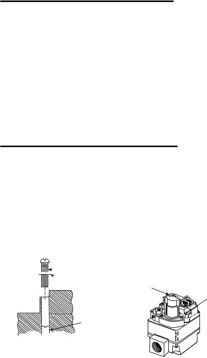
To adjust the pilot gas pressure, remove the cover screw(seefig.8). To REDUCE pilot pressure, turn the pilot adjust screw (beneath the cover screw) clockwise. To INCREASE pilot pressure, turn the pilot adjust screw counterclockwise. Replace and tighten cover screw.
Pilot adjust


 cover screw
 Gasket
Pilot adjust screw
Figure 8. Pilot Gas Adjustment
ADJUSTMENT
PRESSURE REGULATOR
ADJUSTMENT
The pressure regulator has been factory adjusted
(seecontrollabelforspecificsetting).Although additional adjustments will not normally be necessary, you may adjust the regulator. Do not force the adjusting screw beyond the limits that it can easily be adjusted.
1.Energize valve to ignite main burner.
2.Remove “Reg. Adj.” cover screw (see fig. 9).
3.To DECREASE outlet pressure, turn the adjusting screw (beneath the cover screw) counterclockwise. To INCREASE outlet pressure, turn the adjusting screw clockwise.
4.Replace the cover screw. Cycle the valve two or three times to verify regulator setting.
Regulator adjusting |
|
|
cover screw |
|
Pilot adjust |
|
|
|
ON |
T |
cover screw |
|
PILO OF F |
|
Figure 9. Pressure Regulator Adjustment
5
LIGHTING INSTRUCTIONS
FORYOUR SAFETY READ BEFORE OPERATING
!WARNING
Ifyoudonotfollowtheseinstructionsexactly,afireorexplosion may result, causing property damage, personal injury or loss of life.
A.This appliance has a pilot that must be lighted by hand. When lighting the pilot, follow these instructions exactly.
B.BEFORE OPERATING smell all around the applianceareaforgas.Besuretosmellnexttothefloor because some gas is heavier than air and will settle onthefloor.
FORYOUR SAFETY
“WHAT TO DO IFYOU SMELL GAS”
•Donottrytolightanyappliance.
•Donottouchanyelectricalswitch;donotuse any phone in your building.
•Immediatelycallyourgassupplierfromaneighbor’sphone.Followthegassupplier’sinstructions.
•Ifyoucannotreachyourgassupplier,callthefire department.
C.Use only your hand to push in or turn the gas control knob. Never use tools. If the knob will not push in or tun by hand, don’t try to repair it; call a qualifiedservicetechnician.Forceorattempted repairmayresultinafireorexplosion.
D.Do not use this appliance if any part has been underwater.Immediatelycallaqualifiedservice technician to inspect the appliance and to replace any part of the control system and any gas control which has been under water.
LIGHTING INSTRUCTIONS
1.STOP! Read the precautionary information above.
2.Set the thermostat to lowest setting.
3.Turnoffallelectricpowertotheappliance.
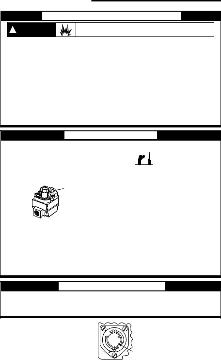
4.Depress gas control knob slightly and turn clockwise to OFF (seefig.10). If knob is in ON, turn clockwise to PILOT, then depress knob slightly and turn clockwise to OFF.
PILO OF F |
Gas Control |
T |
|
|
Knob |
36C Series
NOTE: Knob cannot be turned from PILOT to OFF unless knob is depressed slightly. Do not use tools or excessive force.
5.Waitfifteen(15)minutes to clear out any gas. If you then smell gas, STOP! Follow B in the precautionary information above. If you don’t smell gas, go to next step.
6.Remove the pilot access panel(s) located under the
gas control unit.
7.Find pilot - follow small metal tubes from gas control.
PILOT THERMO-
BURNER COUPLE
8.Turn knob on gas control counterclockwise to PILOT.
9.Depress control knob all the way and hold in. Immediately light the pilot with a match. Continue to hold the control knob down for about one (1) minute after the pilot is lit. Release knob and it will pop back up. Pilot should remain lit. If it goes out, repeat steps 4, 5, 8, and 9.
•Ifknobdoesnotpopupwhenreleased,turnclockwise to OFF, stop and immediately call your service technician or gas supplier.
•Ifthepilotwillnotstaylitafterseveraltries,turn the gas control knob to OFF and call your service
technician or gas supplier.
10.Replacepilotaccesspanel(s).
11.Turn gas control knob counterclockwise to ON.
12.Turn on all electrical power to the appliance.
13.Setthermostattodesiredsetting.
TO TURN OFF GAS TO APPLIANCE
1. |
Set the thermostat to lowest setting. |
3. |
Turn gas control knob clockwise to PILOT. |
|
4. |
Depressgascontrolknobslightlyandturnclockwise |
|||
2. |
Turnoffallelectricpowertotheapplianceifservice |
|||
|
is to be performed. |
|
to OFF. Do not use tools or excessive force. |
|
|
|
|
OFF |
LO |
|
|
|
PI |
T |
|
ON |
|
Indicator 
Figure 10. Gas Cock Knob
Gas cock knob
6

NOTES
7

White-Rodgers is a business of Emerson Electric Co.
The Emerson logo is a |
|
trademark and service mark |
www.white-rodgers.com |
of Emerson Electric Co. |
www.emersonclimate.com |
 Loading...