


TYPE 5A75
WHITE-RODGERS
FAN & LIMIT CONTROL
INSTALLATION INSTRUCTIONS
Operator: Save these instructions for future use!
FAILURE TO READ AND FOLLOW ALL INSTRUCTIONS CAREFULLY BEFORE INSTALLING OR OPERATING THIS CONTROL COULD CAUSE PERSONAL INJURY AND/OR PROPERTY DAMAGE.
DESCRIPTION
The White-Rodgers combination warm air limit and single speed fan control combines into one compact case, a switch which controls the fan or blower operation and also a switch which acts as a safety limit control.
The fan switch is designed to control blower operation. It will start the fan circulating warm air when the bonnet temperature reaches the pre-determined temperature setting; stopping the fan and when the bonnet temperature falls below the predetermined setting.
The warm air limit switch is designed to act as a safety switch which automatically shuts off the burner when the furnace temperature reaches a dangerously high point, regardless of the cause.
The limit switch of these controls has special contacts which are suitable for use on low voltage and millivolt (thermocouple generator type) circuits as well as line voltage equipment such as gas valves, oil burner motors, etc.
PRECAUTIONS
THESE CONTROLS MUST BE INSTALLED BY A QUALIFIED INSTALLER.
Do not exceed the specification ratings.
All wiring must conform to local and national electrical codes and ordinances.
This control is a precision instrument, and should be handled carefully. Rough handling or distorting components could cause the control to malfunction.
This control has been accurately calibrated at the factory. any attempt to calibrate this control will void the White-Rodgers warranty.
 CAUTION
To prevent electrical shock and/or equipment damage, disconnect electric power to system at main fuse or circuit breaker box until installation is complete.
 WARNING
Do not use on circuits exceeding specified voltage. Higher voltage will damage control and could cause shock or fire hazard.
If the furnace manufacturer has made provision for, or recommendations for location of this control, then follow those instructions. If not, the following suggestions should be observed.
The temperature sensitive bulbs should be positioned in the furnace bonnet so that they will be located in the area which is subjected to the most rapid temperature changes.
INSTALLATION
Avoid locations where there may be dead air spots or stratification affecting free air circulation. Corners, sharp turns, baffles or other obstructions usually cause these conditions. Do not locate the control elements where the air-flow from the bonnet into any single duct will control its operation.
|
|
|
|
|
|
WHITE-RODGERS DIVISION |
|
|
|
|
|
|
|
EMERSON ELECTRIC CO. |
|
|
|
|
|
|
|
|
|
|
|
|
|
|
|
9797 REAVIS RD., ST. LOUIS, MO. 63123 |
|
|
|
|
|
|
|
(314) 577-1300, FAX (314) 577-1517 |
Printed in U.S.A. |
|
|
|
|
|
|
||
|
|
|
|
|
|
||
|
|
|
|
|
|
9999 HWY. 48, MARKHAM, ONT. L3P 3J3 |
|
|
|
|
|
|
|
(905) 475-4653, FAX (905) 475-4625 |
|
|
|
|
|
|
|
|
PART NO. 37-0874C
Replaces 37-0874-1 & 37-9098 9549
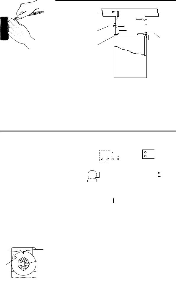
INSTALLATION (CONT.)
The elements should be bent so that they will not touch the heated surface or be affected by reflected or radiated heat unless such a position is determined by the furnace manufacturer.
Care must be used when bending the element to prevent “kinking” it. The element should not be bent with a radius of less than one inch and all bending should be done between the coiled part of the element and a point one inch from the diaphragm cup. The element should be shaped over the thumbs so that a round bend is obtained.
On remote controls, the long capillary tubing between the sensitive bulb and the switch mechanism should be led over a path that will protect it from cuts, blows, wear due to vibration, etc.
Use the paper template packed with the control to obtain the mounting dimensions.
ELEMENT
AFFECTED BY AIR GOING
TO ONLY ONE DUCT
AIR FLOW OVER ELEMENT AFFECTED BU HUMIDIFIER
HUMIDIFIER
 NORMALLY
  GOOD ELEMENT LOCATION
 ELEMENT MAY BE
TOO CLOSE TO
SOURCE OF HEAT
UNLESS SUCH
POSITION IS
DETERMINED BY
FURNACE
MANUFACTURER
WIRING
All wiring should be done in accordance with local and national electrical codes and ordinances.
|
|
|
|
|
|
|
|
|
|
|
|
|
|
|
|
REMOTE MANUAL SWITCH |
||||||||||||||
If the furnace or burner manufacturer recommends a wiring |
|
|
|
|
|
|
|
|
|
|
|
|
FOR SUMMER FAN OPERATION |
|||||||||||||||||
diagram, then follow such recommendations. If none are of- |
|
LIMIT FAN |
|
|
|
|
|
|
|
|
|
|
(IF USED) |
|||||||||||||||||
|
|
|
|
|
|
|
|
|
|
|
|
|
|
|
|
|
||||||||||||||
fered, connect the fan side (right hand switch) as shown in the |
TYPE |
|
|
|
|
|
|
|
|
|
|
|
|
|
|
|
|
|
|
|
|
|
|
|
|
|
|
|||
|
|
|
|
|
|
|
|
|
|
|
|
|
|
|
|
|
|
|
|
|
|
|
|
|
|
|||||
diagram on this page. |
|
|
|
|
|
|
|
|
|
|
|
|
|
|
|
|
|
|
|
|
|
|
|
|
|
|
||||
5A75 |
|
|
|
|
|
|
|
|
|
|
|
|
|
|
|
|
|
|
|
|
|
|
|
|||||||
|
|
|
|
|
|
|
|
|
|
|
|
|
|
|
|
|
|
|||||||||||||
|
|
|
|
|
|
|
|
|
|
|
|
|
|
|
|
|
|
|
|
|
|
|
|
|
|
|||||
|
|
|
|
|
|
|
|
|
|
|
|
|
|
|
|
|
|
|
|
|
|
|
|
|
|
|||||
Connect the limit side (left hand switch) according to wiring |
|
|
|
|
|
|
|
|
|
|
|
|
|
|
|
|
|
|
|
|
|
|
|
|
|
|
|
|
||
|
|
|
|
|
|
|
|
|
|
|
|
|
|
|
|
|
|
|
|
|
|
|
|
|
|
|
|
|||
|
|
|
|
|
|
|
|
|
|
|
|
|
|
|
|
|
|
|
|
|
|
|
|
|
|
|
|
|||
diagrams packed with the primary control, gas valve, oil burner |
|
|
|
|
|
|
|
|
|
|
|
|
|
|
|
|
|
|
|
|
|
|
|
|
|
|
|
HOT |
||
control or stoker control. |
|
|
|
|
|
|
|
|
|
|
|
|
|
|
|
|
|
|
|
|
|
|
|
|
|
|
|
|||
|
|
|
|
|
|
|
|
|
|
|
|
|
|
|
|
|
|
|
|
|
|
|
|
|
|
|
LINE |
|||
|
|
|
|
|
|
|
|
|
|
|
|
|
|
|
|
|
|
|
|
|
|
|
|
|
|
|
|
|
||
|
|
|
|
|
|
|
|
|
|
|
|
|
|
|
|
|
|
|
|
|
|
|
|
|
|
|
|
|
N |
|
|
|
FAN |
|
|
|
|
|
|
|
|
|
|
|
|
|
|
|
|
||||||||||||
SETTING THE CONTROL |
|
MOTOR |
|
|
|
|
|
|
|
|
|
|
|
|
|
|
|
|
||||||||||||
|
|
|
|
|
|
|
|
|
|
|
|
|
|
|
|
|
|
|
|
|
|
|
|
|
|
|
|
|
||
|
|
|
|
|
|
|
|
|
|
|
|
|
|
|
|
|
|
|
|
|
|
|
|
|
|
|
|
|
||
LIMIT SWITCH WITH A FIXED DIFFERENTIAL |
|
|
|
|
|
|
|
|
|
|
|
|
|
|
|
|
|
|
|
|
|
|
|
|
|
|
|
|
||
|
|
|
|
|
CAUTION |
|
|
|
|
|||||||||||||||||||||
The indicator (B) points to the temperature at which the contacts |
|
|
|
|
|
|
|
|
|
|||||||||||||||||||||
The limit control is a safety device. The manufacturer of |
||||||||||||||||||||||||||||||
open. |
||||||||||||||||||||||||||||||
the furnace as well as testing agencies (U.L., AGA, CGA) |
||||||||||||||||||||||||||||||
To set the control: |
||||||||||||||||||||||||||||||
have made many tests on the furnace to determine the |
||||||||||||||||||||||||||||||
Use a screwdriver in the adjusting slot (A) on the front of the |
proper dial setting. |
|
|
|
|
|
|
|
|
|
|
|
|
|
|
|
|
|||||||||||||
control to rotate dial until the desired temperature at which |
The limit dial should never be set any higher than the |
|||||||||||||||||||||||||||||
the contacts will open is positioned directly under the |
||||||||||||||||||||||||||||||
setting it had when the furnace was delivered. Do not |
||||||||||||||||||||||||||||||
indicator (B). |
||||||||||||||||||||||||||||||
force the dial past any stop on the dial even though the |
||||||||||||||||||||||||||||||
|
|
|||||||||||||||||||||||||||||
|
|
dial may be graduated beyond the stop. |
||||||||||||||||||||||||||||
|
|
|
|
|
|
|
|
|
|
|
|
|
|
|
|
|
|
|
|
|
|
|
|
|
|
|
|
|
|
|
“F” STOP TAB |
“B” FIXED |
|
INDICATOR |
||
|
“A” ADJUSTING
SLOT
“E” STOP SCREW
1.Loosen stop screw (E) with enclosed wrench.
2.Set dial to original equipment manufacturer’s specification.
3.Without moving the dial, move stop tab (F) against indicator.
4.Retighten stop screw (E).
2
 Loading...