


by White-Rodgers
Electronic Air Cleaner
240 Volt 50/60 Hz
SST
Super Slim Twin
Model Number 10C27S-010 14C27S-010 20C27S-010
UST
Universal Slim Twin
Model Number 16C27S-010
WHITE-RODGERS
SUPER |
SLIM TWIN |
|
|
AIR CLEANER |
|
ELECTRONIC |
|
|
OPERATING |
||
|
LIGHT |
|
OFF |
|
ON |
|
|
|
OWNERS MANUAL
•Installation
•Operation
•Basic SST/UST Service Guide
•Technical Repair Guide
•Repair Parts
Please read and familiarize yourself with the contents of this manual before installing, operating or performing maintenance on the unit.
UL Listed |
|
Part No. 37-6123D |
|
Replaces 37-6123C |
|
CSA Certified |
Printed In U.S.A. |
0032 |
|
|
RULES FOR SAFE
INSTALLATION
AND OPERATION
Please read instructions before installing and using the Electronic Air Cleaner. This will help you obtain the full benefit from the Electronic Air Cleaner you have selected.
! WARNING
ELECTROCUTION HAZARD
Shut off power at fuse panel before servicing.
Failure to do so could result in serious personal injury or death.
! WARNING
Do not attempt installation of this unit unless you are familiar with the necessary tools, equipment, utility connections and potential hazards.
Installation should be performed only by a qualified service provider.
Failure to do so could result in reduced performance of the unit, serious personal injury or death.
1.Read the Owners Manual and the Rules for Safe Operation carefully. Failure to follow these rules and instructions could cause a malfunction of filter or unsatisfactory service.
2.Follow a regular service and maintenance schedule for efficient operation.
! WARNING
Installation of this unit must comply with local electric codes or other applicable codes.
Review and understand local codes prior to installation.
Failure to do so could result in serious personal injury or death.
! CAUTION
CABINET AND CELLS MAY CON-
TAIN SHARP EDGES.
Use care when servicing unit or handling cells.
Failure to do so could result in minor personal injury.
TABLE OF CONTENTS |
|
Rules for Safe Installation and Operation |
....... 2 |
How the Air Cleaner Works ............................ |
3 |
Construction of the Air Cleaner....................... |
3 |
Preinstallation ................................................. |
4 |
Installation ....................................................... |
6 |
Wiring Instructions .......................................... |
7 |
Operation ........................................................ |
8 |
Maintenance and Washing ............................. |
8 |
Specifications .................................................. |
9 |
Basic SST/UST Service Guide ..................... |
10 |
Technical Repair Guide ................................ |
11 |
Repair Parts .................................................. |
14 |
DID YOU GET THE RIGHT SIZE AIR
CLEANER
Model 10C27S-010 is designed for heating or cooling blowers delivering 600 to 1200 cubic feet of air per minute (cfm.)
Model 14C27S-010 is designed for heating or cooling blowers delivering 1000 to 1600 cfm.
Model 16C27S-010 is designed for heating or cooling blowers delivering 1000 to 2000 cfm.
Model 20C27S-010 is designed for heating or cooling blowers delivering 1600 to 2200 cfm.
See specifications on page 9.
BASIC TOOL REQUIRED
Tin Snip
Screwdriver
Rule or Tape Measure
Drill
2
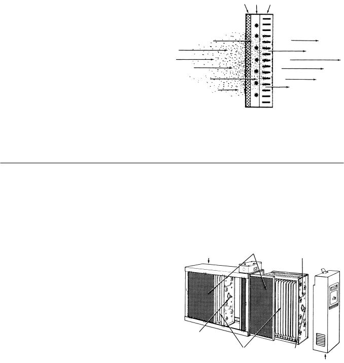
HOW THE AIR CLEANER WORKS
Dirt particles flowing through the ducts (Figure 1) first enters the pre-filters (A) where large particles (hair, lint, etc.) are trapped. Smaller particles (smoke, dust, pollen, etc.) pass through these pre-filters and enter the ionizing section (B). Here each tiny particle receives a positive electrical charge. These charged particles then enter the collecting section (C). This section consists of a series of aluminum plates which are alternately charged negative and positive.
The positive charge of the particles cause them to be repelled by the positive plates and attracted to the negative plates where they are collected . . . just as a magnet attracts iron filings.
Clean-filtered air re-enters the supply duct system.
A B C
Dirty Air In |
Clean Air Out |
Figure 1
CONSTRUCTION OF THE AIR CLEANER
Not only is your air cleaner easy to install, it is also easy to operate and maintain. Its basic components, and their functions, are as follows: (See Figure 2)
Cabinet - mounts to existing duct work and houses the collecting cells and pre-filters.
Collecting Cells - are made in two sections and perform the actual collecting of dust, dirt, and other impurities from the air. They contain the ionizing and collection sections described above.
Each cell must be installed with the ionizing wires on the air entering side. Each cell must be oriented with the handles and contact button (Figure 2) toward the operator.
Pre-filters - are in two sections which are interchangeable. They serve as a pre-filter to trap large particles such as hair and lint before they can enter the cell sections.
Power Pack- contains operating light as well as the power supply that converts the 240 volt power to the high-voltage, direct current required for the collecting cell.
Cabinet |
Pre-Filters |
Handle |
Contact
Button
Collecting Cells |
Contact |
|
Button |
Power Pack
Figure 2
3
PREINSTALLATION
Not to Exceed 20°
Air Flow
Furnace |
Air Flow |
|
|
Opening |
|
|
Electronic |
|
Air Cleaner |
|
Opening |
Furnace |
Electronic |
Transition Section |
Air Cleaner |
(if Needed) |
|
Figure 3
LOCATING THE AIR FILTER
Your air filter must be mounted in the return air duct of a central forced-air system, on the air entering side of your furnace. (See Figure 3 for example.)
Select a location that meets the following:
1.The face of the cell will be at a right angle to the air stream.
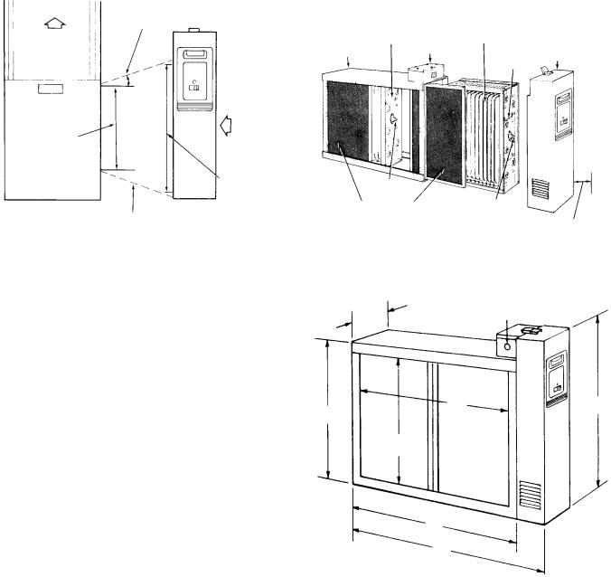
2.Allow the following clearances to permit removal of cells and pre-filters: (See Figures 4 and 5)
Model 10C27S-010 - 14 inches Model 14C27S-010 - 15 inches Model 16C27S-010 - 14 inches Model 20C27S-010 - 15 inches
For complete dimension data refer to Figure 5.
3.The air filter is not to be placed in the discharge of either the heating or cooling unit.
4.IMPORTANT: If atomizing spray type humidifier is used, it must be installed downstream from the air filter.
If your furnace duct system has a pre-installed boot, discard front cover of boot and slide the air cleaner component inside the boot. (Applies to 14C27S-010 and 20C27S-010.)
If furnace opening cannot be enlarged to required size, a transition sheet metal section must be used. Transition must be planned for each job. Reduction should not be more than 4 inches per linear foot, approximately 20 angular degrees (Figure 3).
DIRECTION OF AIR FLOW THROUGH THE
AIR CLEANER
Your air cleaner is shipped from the factory with air flow from left-to-right. If this air flow is suitable for the installation, no further changes need to be made (Figure 4). For right-to-left air flow, remove both pre-filter and cell sec-
(Interchangeable) |
(Interchangeable) |
Collecting Cell |
Collecting Cell |
Cabinet |
Outlet Box |
Power Pack |
|
|
Handle |
Contact |
|
|
|
Button |
Contact |
|
|
Pre-Filters |
|
||
Button |
|
||
(Interchangeable) |
See text for Cell |
||
|
Removal Clearance
Figure 4
|
Knockouts for |
|
6 7/8" |
3/4" Conduit |
|
(three sides) |
||
|
C |
F |
E |
|
D |
|
B
A
MODEL NO. |
|
A |
B |
C |
D |
E |
F |
10C27S-010 |
24 3/4 |
21 5/16 |
18 5/8 |
13 9/16 |
16 7/16 |
19 1/16 |
|
14C27S-010 |
29 |
11/16 |
26 1/4 |
23 5/8 |
13 9/16 |
16 7/16 |
19 1/16 |
16C27S-010 |
25 1/2 |
21 5/16 |
18 5/8 |
17 3/4 |
20 5/8 |
23 3/8 |
|
20C27S-010 |
29 |
11/16 |
26 1/4 |
23 5/8 |
17 3/4 |
20 5/8 |
23 3/8 |
Figure 5
tions. Turn cells upside down (with the same end facing the cabinet opening). This will locate the ionizing wires at the right, and both contact buttons and cell handles will be facing the power door. Air flow direction must agree with arrow embossed on end of collecting cells.
After installing the cell sections, install pre-filters in cabinet tracks on the right. This will again place the pre-filters on the air entering side (on the same side as ionizing wires).
4

TYPICAL MOUNTING POSITIONS
Air Flow
Air Flow
Air Flow
Rear View |
Rear View |
|
Figure 6 |
Figure 8 |
|
Figure 7 |
BASEMENT FURNACE (LOWBOY) (Figure 6)
Cleaner is mounted horizontally in return plenum, just above furnace.
COUNTERFLOW
FURNACE (Figure 7)
Cleaner is mounted horizontally in return duct or plenum, just above furnace.
HIGHBOY FURNACE (Figure 9)
Installation beneath furnace. Cleaner mounts horizontally, where return air enters from below. Raise furnace and install beneath base.
HIGHBOY FURNACE (Figure 8)
Side installation. Cleaner is mounted vertically, where return air enters side inlet of furnace.
Less than |
|
7 Inches |
Offset |
|
At Least
9 Inches
|
Air Flow |
|
Figure 10 |
|
OFFSET INSTALLATION |
Figure 9 |
(Figure 10) |
|
Typical use of duct offset to match air filter opening. |
|
If duct connection to furnace allows less than nine |
|
inches for mounting the air cleaner, shorten the |
|
lateral trunk, or attach an offset fitting to the elbow. |
Air Flow
HORIZONTAL FURNACE (Figure 11)
Cleaner is mounted vertically in the return duct near furnace.
Figure 11
5
 Loading...