


50A55-843
Universal Integrated Furnace Control
INSTALLATION INSTRUCTIONS
Operator: Save these instructions for future use!
FAILURE TO READ AND FOLLOW ALL INSTRUCTIONS CAREFULLY BEFORE
INSTALLING OR OPERATING THIS CONTROL COULD CAUSE PERSONAL
INJURY AND/OR PROPERTY DAMAGE.
The 50A55-843 is an automatic gas interrupted ignition control
that employs a microprocessor to continually monitor, analyze,
and control the proper operation of the gas burner, inducer, and
fan.
Signals interpreted during continual surveillance of the thermostat and flame sensing element initiate automatic ignition of the
burner, sensing of the flame, and system shut-off during normal
operation.
TRANE APPLICATION - Installer MUST read page 3 “Mounting and Wiring”
Installation should be done by a qualified heating and air
conditioning contractor or licensed electrician.
If in doubt about whether your wiring is millivolt, line, or low
voltage, have it inspected by a qualified heating and air conditioning contractor or licensed electrician.
Do not exceed the specification ratings.
All wiring must conform to local and national electrical codes and
ordinances.
This control is a precision instrument, and should be handled
carefully. Rough handling or distorting components could cause
the control to malfunction.
Following installation or replacement, follow manufacturer’s
recommended installation/service instructions to ensure proper
operation.
CAUTION
Do not short out terminals on gas valve or primary
control. Short or incorrect wiring may damage the
thermostat.
CONTENTS
Description ........................................................ 1
Precautions ....................................................... 1
Specifications .................................................... 2
Installation......................................................... 3
Mounting & Wiring
Operation .......................................................... 6
Mounting Hole Template .................................... 8
These controls incorporate system fault analysis for quick gas
flow shut-off, coupled with automatic ignition retry upon sensing
a fault correction.
Failure to comply with the following
warnings could result in personal injury
or property damage.
FIRE HAZARD
• Do not exceed the specified voltage.
• Protect the control from direct contact with water
(dripping, spraying, rain, etc.).
• If the control has been in direct contact with water,
replace the control.
• Label all wires before disconnection when servicing controls. Wiring errors can cause improper
and dangerous operation.
• Route and secure wiring away from flame.
SHOCK HAZARD
• Disconnect electric power before servicing .
• Ensure proper earth grounding of appliance.
• Ensure proper connection of line neutral and line
hot wires.
EXPLOSION HAZARD
• Shut off main gas to appliance until installation is
complete.
50A55-843
DESCRIPTION
PRECAUTIONS
WARNING
White-Rodgers is a division
of Emerson Electric Co.
www.white-rodgers.com
PART NO. 37-6265G
Replaces 37-6265F
0526
SPECIFICATIONS
ELECTRICAL RATINGS [@ 77°F (25°C)]:
Input Voltage: 25 VAC 50/60 Hz
Max. Input Current @ 25 VAC: 0.45 amp
Relay Load Ratings:
Valve Relay: 1.5 amp @ 25 VAC 50/60 Hz 0.6 pf
Ignitor Relay: 6.0 amp @ 120 VAC 50/60 Hz
(resistive)
Inducer Relay: 2.2 FLA–3.5 LRA @ 120 VAC
Circulator Relay: 14.5 FLA–25.0 LRA @ 120 VAC
Flame Current Requirements:
Minimum current to insure flame detection: 1 µa DC*
Maximum current for non-detection: 0.1 µa DC*
Maximum allowable leakage resistance: 100 M ohms
*Measured with a DC microammeter in the flame probe lead
OPERATING TEMPERATURE RANGE:
-40° to 175°F (-40° to 80°C)
HUMIDITY RANGE:
5% to 93% relative humidity (non-condensing)
MOUNTING:
Surface mount multipoise
Timing Specs: (@ 60 Hz**)
maximum
Flame Establishing Time: 0.8 sec
Flame Failure Response Time: 2.0 sec
** At 50 Hz, all timing specifications should be increased by
20%
Gases Approved: Natural, Manufactured, Mixed, Liquified
Petroleum, and LP Gas Air Mixtures are all approved for use.
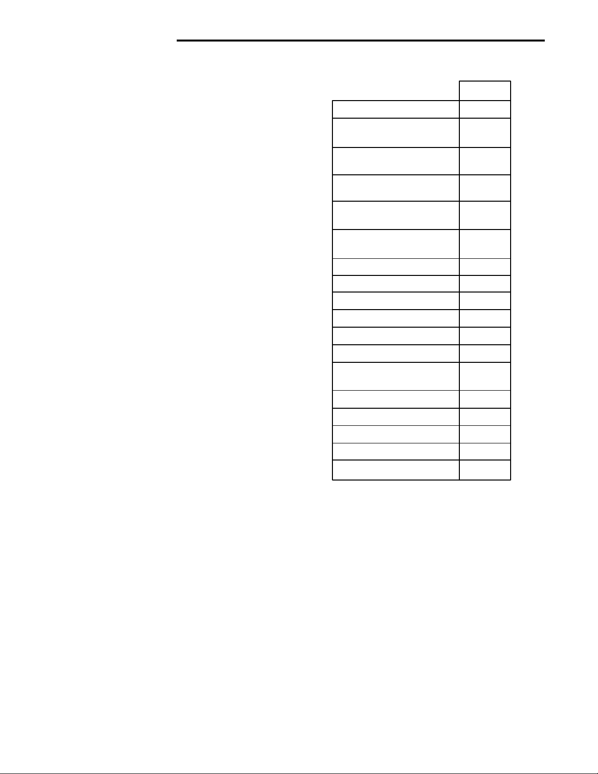
(All times are in seconds, unless noted otherwise)
TIMING SPECIFICATIONS
50A55-843
PRE-PURGE
INITIAL IGNITOR WARM-UP
(1st 64 attempts)
MINIMUM IGNITOR WARM-
UP
MAXIMUM IGNITOR WARM-
UP
IGNITION ACTIVATION
PERIOD
TRIAL FOR IGNITION
PERIOD
RETRIES
VALVE SEQUENCE PERIOD
INTERPURGE
POST-PURGE
LOCKOUT TIME
HEAT DELAY-TO-FAN-ON*
HEAT DELAY-TO-FAN-OFF*
COOL DELAY-TO-FAN-ON
COOL DELAY-TO-FAN-OFF*
AUTO RESET
30
17
5
21
1
4
2 times
12
60
15
300
30, 45
60/90/
120/180
5
45, 90
60 minutes
HUMIDIFIER
ELECTRONIC AIR CLEANER
* These times will vary depending on
option switch position. The control is
factory-set at 30 seconds heat delayto-fan-on, 180 seconds heat delay-tofan-off and 45 seconds cool delay-tofan-off. See OPERATION section for
further information.
YES
YES
2
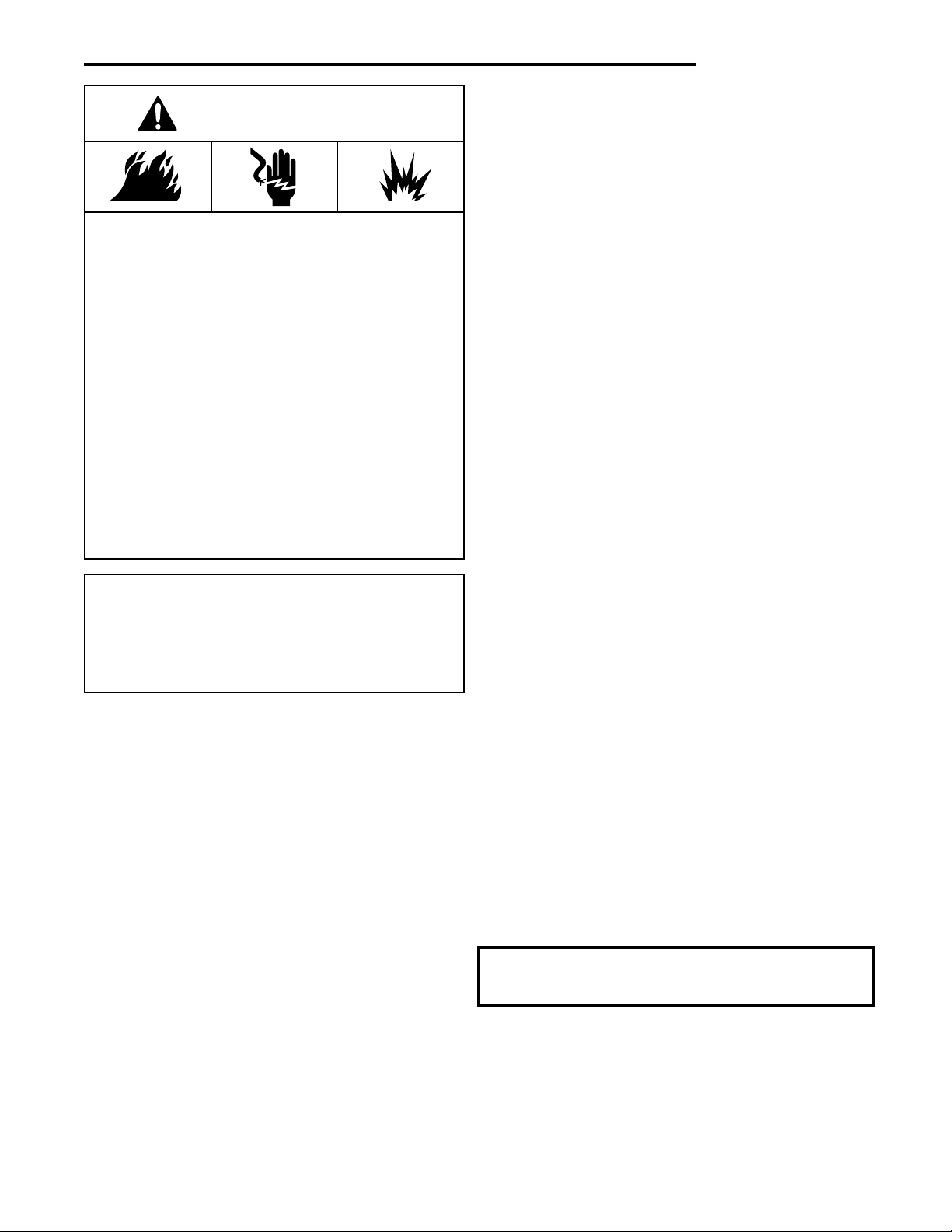
WARNING
FIRE HAZARD
• Do not exceed the specified voltage.
• Replace existing control with exact model and
dash number.
• Protect the control from direct contact with water
(dripping, spraying, rain, etc.).
• Label all wires before disconnection when servicing controls. Wiring errors can cause improper
and dangerous operation.
• Route and secure wiring away from flame.
SHOCK HAZARD
• Disconnect electric power before servicing .
• Ensure proper earth grounding of appliance.
• Ensure proper connection of line neutral and line
hot wires.
EXPLOSION HAZARD
• Shut off main gas to appliance until installation is
complete.
CAUTION
Do not short out terminals on gas valve or primary
control. Short or incorrect wiring may damage the
thermostat.
INSTALLATION
MOUNTING AND WIRING
All wiring should be installed according to local and national
electrical codes and ordinances.
The control must be secured to an area that will experience a
minimum of vibration and remain below the maximum ambient
temperature rating of 175°F. The control is approved for minimum ambient temperatures of -40°F.
When mounting the control, any orientation is acceptable.
Choose a location that will not damage, obstruct or place stress
on the control’s terminations, system wiring harness or system
components. After finding a suitable location, drill four (4) 1¦8”
holes for mounting control. To ensure proper mounting hole
locations, there is a mounting hole template on page 8 of this
instruction sheet. Detach the page with the template from the
instruction sheet and apply it to the mounting location. When
drilling the holes, take care so that the transformer, wiring
harness or other system components are not damaged. Four (4)
#8 sheet metal screws are provided to complete the installation.
Refer to the wiring diagram and wiring table when connecting
the 50A55 control to other components of the system.
UL approved, 105°C rated 18 gauge, stranded,
tion wire is recommended for all low voltage safety circuit
connections. Refer to 50A55 specification sheet for recommended terminals to mate with those on the control.
UL approved 105°C rated 16 gauge min., stranded, 4¦64” thick
insulation wire is recommended for all line voltage connections.
Refer to 50A55 specification sheet for recommended terminals
to mate with those on the control.
After installation or replacement, follow appliance manufacturer’s
recommended installation or service instructions to ensure
proper operation.
The 50A55 has only one serviceable part–an automotive type
fuse, which protects the low voltage transformer from damage
if its output is short-circuited. If the fuse has opened up, remove
whatever caused the short circuit and replace the fuse with only
a 3 Amp automotive type fuse. If the fuse is not the cause of the
control’s problem, replace the entire 50A55 control. There are
no other user serviceable parts.
Additional jumper wires are included in this package and
should be used if the original wiring does not reach the control
after mounting. Refer to the furnace wiring diagram for proper
connection of the wires.
Amana/Goodman application - An additional wiring harness
(WR 115-0223) is included in this package. If the control being
replaced has a 2-pin (inducer/ignitor) connector, this wiring
harness will adapt the furnace wiring to the 4-pin connector of
the replacement control.
2
¦64” thick insula-
Trane application - Jumper wire 151-2906 (provided with
control) must be installed on the furnace from R01 to R02 of the
12-pin connector.
3
 Loading...