


80 Series Thermostat
Wiring Diagrams for 1F83-0422 & 1F85-0422
Single Stage, Multi-Stage, Heat Pump
Heat Pump Connections
If you do not have a heat pump system, refer to figures 2 & 3. Refer to equipment manufacturers’ instructions for specific system wiring information.
You can configure the thermostat for use with the following heat pump systems.
HEAT PUMP TYPE 1 (HP 1). Single stage compressor system; gas or electric backup.
Figure 1 – Heat Pump Systems
|
|
|
|
|
|
|
|
|
|
Jumper |
|
|
|
Jumper |
|
|
NOTE: If your system |
||||
|
L |
O/B |
Y |
Y2 |
W/E |
W2 |
G |
RH |
RC |
C |
does not provide an E |
||||||||||
|
connection, jumper W2 to |
||||||||||||||||||||
|
|
|
|
|
|
|
|
|
|
|
|
|
|
|
|
|
|
|
|
|
|
System |
|
|
|
|
|
|
|
|
|
|
|
|
|
|
|
|
|
|
|
|
W/E to use the Auxiliary |
|
|
|
|
|
|
|
|
|
|
|
|
|
|
|
|
|
|
|
|
|
Heat in the Emergency |
|
|
|
O |
|
|
|
|
|
|
|
|
Blower/ |
|
|
|
|
|
|
|||
|
|
|
|
|
|
|
|
|
|
|
|
|
|
|
|
|
Mode. |
||||
|
Fault Indicator |
Energized in |
|
|
|
|
|
|
|
|
Circulator |
|
|
|
|
|
|
||||
|
Cool Mode |
Heat and |
|
|
Emergency |
Heat Mode |
Fan Energized |
|
|
|
|
Optional* |
|
||||||||
|
or |
|
|
|
|
2nd Stage. |
on Call for |
24 Volt |
24 Volt |
* Common connection |
|||||||||||
Heat Pump 1 |
B |
Cool Mode |
No |
24 Volt |
|||||||||||||||||
(HP1) |
System |
1st Stage |
Output |
Mode |
Emergency |
Heat or Cool. |
(Hot) |
(Hot) |
(Com- |
required for fault or |
|||||||||||
|
Malfunction |
Energized in |
(Compressor) |
|
|
1st Stage |
Mode 2nd |
Set Elect/Gas |
Heat |
Cool |
mon) |
||||||||||
|
Switch |
Heat, Off, |
|
|
|
|
|
|
Stage |
Option for |
|
|
|
|
|
|
malfunction indication. |
||||
|
|
|
Emergency |
|
|
|
|
|
|
|
|
Emergency |
|
|
|
|
|
|
|||
|
|
|
Mode |
|
|
|
|
|
|
|
|
Mode |
|
|
|
|
|
|
|
||
|
|
|
|
|
|
|
|
|
|
|
|
|
|
|
|
|
|
|
|
|
|
Comfort Alert II Module
or Similar System
Malfunction Module
NEUTRAL |
|
24VAC |
120VAC |
HOT |
|
CLASS II |
|
TRANSFORMER |
|
Single Stage and Multi-Stage Connections
Refer to equipment manufacturers’ instructions for specific system wiring information.
This thermostat is designed to operate a single-transformer or twotransformer system.
You can configure the thermostat for use with the following fossil fuel systems:
SINGLE STAGE (SS 1) gas, oil or electric. MULTI-STAGE (MS 2) gas, oil or electric.
After wiring, see INSTALLER CONFIGURATION section for proper thermostat configuration.
Figure 2 – Single Stage or Multi-Stage System (No Heat Pump) with Single Transformer
Jumper
|
|
L |
O/B |
Y |
Y2 |
W/E |
W2 |
G |
RH |
RC |
C |
|||||||||||
System |
|
|
|
|
|
|
|
|
|
|
|
|
|
|
|
|
|
|
|
|
|
|
|
|
|
|
|
|
|
|
|
|
|
|
|
|
|
|
|
|
|
|
|
|
|
Single |
|
|
|
|
O |
|
|
|
|
|
|
|
|
Blower/ |
|
|
|
|
|
|
||
Fault |
Energized Constantly |
|
|
|
|
|
|
|
|
|
|
|
|
|
|
|||||||
Stage 1 |
|
|
|
|
|
|
No Output |
Circulator |
|
|
|
|
|
|
||||||||
in |
|
|
|
|
|
|
|
|
|
|
|
|
||||||||||
(SS1) |
Indicator |
|
|
No |
Heat |
|
|
Fan Energized |
24 Volt |
24 Volt |
Optional* |
|||||||||||
Cool Mode |
|
|
|
|
||||||||||||||||||
|
or |
Cool Mode |
Output |
Mode |
|
|
on Call for |
(Hot) |
(Hot) |
24 Volt |
||||||||||||
|
|
|
|
|
||||||||||||||||||
|
System |
B |
1st Stage |
|
|
1st Stage |
|
|
Cool (and |
Heat |
Cool |
(Com- |
||||||||||
Multi- |
Malfunction |
|
|
Cool |
|
|
Heat Mode |
Heat if |
|
|
|
|
mon) |
|||||||||
Stage 2 |
Switch |
Energized Constantly |
|
|
Mode |
|
|
2nd Stage |
configured |
|
|
|
|
|
|
|||||||
(MS2) |
|
|
|
|
in Heat, Off, |
|
|
2nd |
|
|
|
|
for Electric |
|
|
|
|
|
|
|||
|
|
|
|
|
Emergency |
|
|
Stage |
|
|
|
|
Heat) |
|
|
|
|
|
|
|||
|
|
|
|
|
Mode |
|
|
|
|
|
|
|
|
|
|
|
|
|
|
|
|
|
|
|
|
|
|
|
|
|
|
|
|
|
|
|
|
|
|
|
|
|
|
|
|
*Common connection required for fault or
malfunction indication.
Comfort Alert II Module
or Similar System
Malfunction Module
NEUTRAL |
|
24VAC |
120VAC |
HOT |
|
CLASS II |
|
TRANSFORMER |
|
www.white-rodgers.com |
PART NO. 37-6895B |
Replaces 37-6895A |
|
|
0825 |
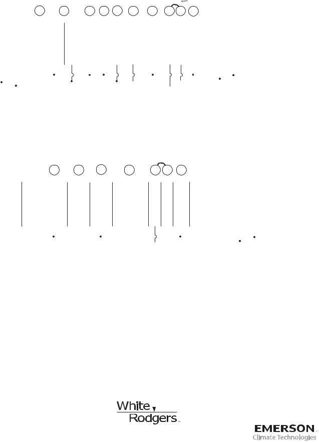
Figure 3 – Single Stage or Multi-Stage System (No Heat Pump) with Two Transformers
|
|
|
|
|
|
|
|
|
|
|
|
|
|
|
|
|
|
|
|
|
|
|
|
|
|
|
|
|
|
|
|
|
|
|
NOTE: If continuous backlight or |
||
|
|
|
|
|
|
|
|
|
|
|
|
|
|
|
|
|
|
|
|
|
|
|
|
|
|
|
|
|
Remove Jumper Wire |
hardwired power input are desired but |
|||||||
|
|
|
|
|
|
|
|
|
|
|
|
|
|
|
|
|
|
|
|
|
|
|
|
Jumper |
|
|
do not function in both HEAT and COOL |
||||||||||
|
|
|
|
|
|
|
|
|
|
|
|
|
|
|
|
|
|
|
|
|
|
|
|
|
|
between RH & RC |
|||||||||||
|
|
|
|
|
|
|
|
L |
|
O/B |
Y |
Y2 |
W/E |
W2 |
G |
RH |
RC |
|
C |
modes, cut the heating transformer 24V |
|||||||||||||||||
|
|
|
|
|
|
|
|
|
|
wires and tape off. Connect the neutral |
|||||||||||||||||||||||||||
|
|
|
|
|
|
|
|
|
|
|
|
|
|
|
|
|
|
|
|
|
|
|
|
|
|
|
|
|
|
|
|
|
|
|
|||
|
|
|
|
|
System |
|
|
|
|
|
|
|
|
|
|
|
|
|
|
|
|
|
|
|
|
|
|
|
|
|
|
circuit disconnected from the heating |
|||||
|
|
|
|
|
|
|
|
|
|
|
|
|
|
|
|
|
|
|
|
|
|
|
|
|
|
|
|
|
|
|
|
|
|
|
transformer to the neutral circuit of the |
||
|
|
|
|
|
|
|
|
|
|
|
|
|
|
|
|
|
|
|
|
|
Blower/ |
|
|
|
|
|
|
|
|
|
|
|
|
||||
|
|
|
|
|
Single |
|
|
|
O |
B |
|
|
|
|
|
|
No Output |
|
|
|
|
|
|
|
|
|
|
|
|
cooling transformer. Disconnect the wire |
|||||||
|
|
|
|
|
Stage 1 |
|
|
|
|
|
|
|
|
Circulator |
|
|
|
|
|
|
|
|
|
|
|
|
to the RH terminal and install a jumper |
||||||||||
|
|
|
|
|
(SS1) |
|
Fault |
Energized |
Energized |
|
|
No |
Heat |
|
|
Fan Energized |
24 Volt |
24 Volt |
Optional |
|
|
|
|
||||||||||||||
|
|
|
|
|
|
|
|
Indicator |
Constantly |
Constantly |
Cool Mode |
Output |
Mode |
|
|
on Call for |
(Hot) |
(Hot) |
|
24 Volt |
|
|
|
|
between RH and RC. Depending on |
||||||||||||
|
|
|
|
|
|
|
|
(NOT |
in |
in Heat, Off, |
1st Stage |
|
|
1st Stage |
|
|
Cool (and |
Heat |
Cool |
|
(Com- |
|
|
|
|
the system requirements, replace the |
|||||||||||
|
|
|
|
|
Multi- |
|
USED) |
Cool Mode |
Emergency |
|
|
Cool |
|
|
Heat Mode |
Heat if |
|
|
|
|
|
|
mon) |
|
|
|
|
||||||||||
|
|
|
|
|
|
|
|
Mode |
|
|
|
|
|
|
|
|
|
|
|
|
|
|
|||||||||||||||
|
|
|
|
|
Stage 2 |
|
|
|
|
|
|
Mode |
|
|
2nd Stage |
configured |
|
|
|
|
|
|
|
|
|
|
|
|
cooling transformer with a 75VA class II |
||||||||
|
|
|
|
|
|
|
|
|
|
|
|
|
|
for Electric |
|
|
|
|
|
|
|
|
|
|
|
|
|||||||||||
|
|
|
|
|
(MS2) |
|
|
|
|
|
|
|
|
2nd |
|
|
|
|
|
|
|
|
|
|
|
|
|
|
|
|
transformer if needed. |
||||||
|
|
|
|
|
|
|
|
|
|
|
|
|
|
|
Stage |
|
|
|
|
Heat) |
|
|
|
|
|
|
|
|
|
|
|
|
|||||
|
|
|
|
|
|
|
|
|
|
|
|
|
|
|
|
|
|
|
|
|
|
|
|
|
|
|
|
|
|
|
|
|
|
|
|
|
|
|
|
|
|
|
|
|
|
|
|
|
|
|
|
|
|
|
|
|
|
|
|
|
|
|
|
|
|
|
|
|
NEUTRAL |
|
|
|
|
|
|
|
|
|
|
|
|
NEUTRAL |
|
|
|
|
|
|
|
|
|
|
|
|
|
|
|
|
|
|
|
|
|
24VAC |
|
|
|
|
120VAC |
||||
|
|
|
|
|
|
|
|
|
|
|
|
|
|
|
|
|
|
|
|
|
|
|
|
|
|
|
|
|
|
|
|||||||
|
|
|
|
|
|
|
|
|
|
|
|
|
|
|
|
|
|
|
|
|
|
|
|
|
|
|
HOT |
|
|
|
|
|
|
||||
120VAC |
|
|
|
|
|
24VAC |
|
|
|
|
|
|
|
|
|
|
|
|
|
|
|
|
|
|
|
|
|
|
|
|
|
COOLING |
|||||
|
|
|
|
|
|
|
|
|
|
|
|
|
|
|
|
|
|
|
|
|
|
|
|
|
|
|
|
|
|
||||||||
|
|
|
|
|
|
|
|
|
|
|
|
|
|
|
|
|
|
|
|
|
|
|
|
|
|
|
|
|
|
||||||||
|
|
|
|
|
|
|
HOT |
|
|
|
|
|
|
|
|
|
|
|
|
|
|
|
|
|
|
|
|
|
|
|
|
|
|
||||
|
|
|
|
|
|
|
|
|
|
|
|
|
|
|
|
|
|
|
|
|
|
|
|
|
|
|
|
|
CLASS II |
|
|
|
|||||
HEATING |
|
|
|
|
|
|
|
|
|
|
|
|
|
|
|
|
|
|
|
|
|
|
|
|
|
|
|
|
|
|
|
|
|||||
|
|
|
|
|
|
|
|
|
|
|
|
|
|
|
|
|
|
|
|
|
|
|
|
|
|
TRANSFORMER |
|||||||||||
|
|
CLASS II |
|
|
|
|
|
|
|
|
|
|
|
|
|
|
|
|
|
|
|
|
|
|
|
|
|||||||||||
|
|
|
|
|
|
|
|
|
|
|
|
|
|
|
|
|
|
|
|
|
|
|
|
|
|
|
|
|
|
|
|
|
|||||
|
TRANSFORMER |
|
|
|
|
|
|
|
|
|
|
|
|
|
|
|
|
|
|
|
|
|
|
|
|
|
|
|
|
|
|
|
|||||
Figure 4 – 3-Wire (SPDT) Heat Only Zone Valve Wiring
Jumper
|
6 |
Y |
W |
G |
RH |
RC |
C |
|||||||
System |
|
|
|
|
|
|
|
|
|
|
|
|
|
|
|
|
|
|
|
|
|
|
|
|
|
|
|
|
|
|
|
|
|
|
|
|
|
|
|
|
|
|
|
|
Single Stage |
|
|
|
|
|
|
|
|
|
|
|
|
Constant |
|
3-wire |
Closes |
|
|
Opens |
Blower/Circulator |
24 Volt |
24 Volt |
|||||||
|
|
24 Volt |
||||||||||||
Zone Valve |
Valve |
|
|
Valve |
Fan Energized |
(Hot) |
(Hot) |
(Com- |
||||||
application |
(6) |
|
|
|
(4) |
|
|
|
Heat |
Cool |
mon) |
|||
|
|
|
|
|
|
|
|
|
(5) |
|
|
|
|
|
|
|
|
|
|
|
|
|
|
|
|
|
|
|
|
|
|
|
|
|
NEUTRAL |
|
|
|
|
|
|
|
|
|
|
|
|
|
|
|
|
|
|
|
|
|
|
|
|
|
|
|
|
|
|
|
|
24VAC |
|
|
|
120VAC |
|
|
|
|
|
|
HOT |
|
|
|
|
|
|
|
|
|
|
|
|
|
|
|
|
CLASS II
TRANSFORMER
White-Rodgers is a division of Emerson Electric Co.
The Emerson logo is a trademark and service mark of Emerson Electric Co.
St. Louis, Missouri www.white-rodgers.com
 Loading...