


 WHITE-RODGERS
TEMPERATURE CONTROL
SPDT Remote Bulb
INSTALLATION INSTRUCTIONS
Operator: Save these instructions for future use!
FAILURE TO READ AND FOLLOW ALL INSTRUCTIONS CAREFULLY BEFORE INSTALLING OR OPERATING THIS CONTROL COULD CAUSE PERSONAL INJURY AND/OR PROPERTY DAMAGE.
This control is designed for use on equipment that requires a closed circuit for both rise and fall in temperature. The single pole, double throw switch action offers both open-on-rise terminals as well as close-on-rise terminals.
DESCRIPTION
This control has capillary tubing between the temperature sensitive bulb and the switch mechanism, permitting the switch mechanism to be mounted at any convenient location while the temperature sensitive bulb is located in the fluid or medium being controlled.
THIS CONTROL MUST BE INSTALLED BY A QUALIFIED INSTALLER.
All wiring must conform to local and national electrical codes and ordinances.
This control is a precision instrument, and should be handled carefully. Rough handling or distorting components could cause the control to malfunction.
This control has been accurately calibrated at the factory. Any attempt to calibrate this control will void the WhiteRodgers warranty.
!WARNING
Do not use on circuits exceeding specified voltages. Higher voltages will damage control and could cause shock or fire hazard.
If in doubt about whether your wiring is millivolt, low or line voltage, have it inspected by a qualified heating and air conditioning contractor or a licensed electrician.
PRECAUTIONS
! CAUTION
To prevent electrical shock and/or equipment damage, disconnect electric power to system at main fuse or circuit breaker box until installation is complete.
Label all wires prior to disconnection when servicing controls. Wiring errors can cause improper and dangerous operation.
Following installation or replacement, follow appliance manufacturers’ recommended installation/service instructions to insure proper operation.
The switch mechanism of this control may be mounted in any location, provided that the temperature and humidity of the air in which it is located do not cause a condensation on the switch parts.
The sensitive element, or “bulb”, should be located in the average temperature of the controlled area.
Capillary tubing should be led over a path that protects it from damage from blows, cuts, etc., and should be installed without kinking or twisting. The tubing should be
INSTALLATION
attached to some surface at frequent intervals along its length, and should not hang loosely. Excess tubing should be coiled and secured at a convenient protected location close to the switch mechanism.
The bulb should be handled with reasonable care, as a dent or sharp bend may change the calibration and cause the control to cycle at a temperature different from the dial setting.
|
|
|
|
|
|
WHITE-RODGERS DIVISION |
|
|
|
|
|
|
|
EMERSON ELECTRIC CO. |
|
|
|
|
|
|
|
|
|
|
|
|
|
|
|
9797 REAVIS RD., ST. LOUIS, MO. 63123-5398 |
|
|
|
|
|
|
|
(314) 577-1300, FAX (314) 577-1517 |
Printed in U.S.A. |
|
|
|
|
|
|
||
|
|
|
|
|
|
9999 HWY. 48, MARKHAM, ONT. L3P 3J3 |
|
|
|
|
|
|
|
(905) 475-4653, FAX (905) 475-4625 |
|
PART NO. 37-1637C
Replaces 37-1637B 9722
Wiring
All wiring must conform to local and national electrical codes and ordinances.
Connect in accordance with the wiring diagrams provided by the equipment manufacturer.
This control has a single-pole, double-throw, snap-action switch. The top left-hand terminal (red) is the common terminal. The top right-hand terminal (blue) has an open- on-rise switch action. The bottom center terminal (white) has close-on-rise switch action.
RED BLUE
OPEN ON RISE
COMMON
OF TEMPERATURE
 WHITE
WHITE
CLOSE ON RISE
OF TEMPERATURE
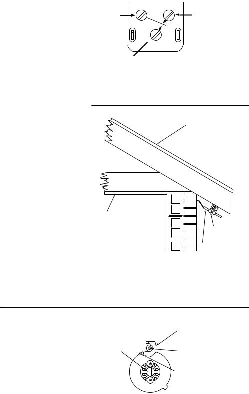
INSTALLATION AS AN OUTDOOR BULB
When used as a changeover control or outdoor thermostat, the bulb of this control should be located to measure the actual outdoor air temperature. A mounting bracket is provided for mounting the bulb.
The mounting bracket should be fastened to some convenient outside part of the building that is shielded from the direct rays of the sun, the direct fall of rain and snow, and sufficiently above ground to keep it out of snow and ice.
The underside of the eaves or overhang of a NORTH or NORTHEAST roof is a good location. It should be exposed to the circulation of air and wind.
ROOF
CEILING
MOUNTING
BRACKET
OUTDOOR BULB
SETTING THE DIAL
The fixed indicator (B) points to temperature at which the “R-B” contacts close and the “R-W” contacts open. Follow these instructions to set the dial.
1.Insert a screwdriver in the adjusting slot (A) and turn the dial until the fixed indicator (B) points to the lowest temperature of the cycle.
2.Turn the differential adjusting screw (C) until the moveable indicator (D) points to the highest temperature of the cycle.
|
“B” FIXED INDICATOR |
“A” ADJUSTING |
|
SLOT |
“C” DIFFERENTIAL |
|
ADJUSTING SCREW |
|
“D” MOVABLE INDICATOR |
2
 Loading...