


WHITE-RODGERS
11D05, 11D18, 11D31, 11D55
WELL IMMERSION
HOT WATER CONTROL
INSTALLATION INSTRUCTIONS
Operator: Save these instructions for future use!
FAILURE TO READ AND FOLLOW ALL INSTRUCTIONS CAREFULLY BEFORE INSTALLING OR OPERATING THIS CONTROL COULD CAUSE PERSONAL
INJURY AND/OR PROPERTY DAMAGE.
DESCRIPTION
These controls are designed for use on hot water heating installations. They have; open on rise, close on rise, or S.P.D.T. switch action and are available with either fixed or adjustable differential.
These controls are shipped with the bulb and capillary in the horizontal position. Some of these models also have excess capillary stored within the enclosure permitting them to be used with wells having either a standard or extended shank.
Another model is available with open-on-rise manual reset feature. Most controls can be used on either horizontal or vertical well installation.
THESE CONTROLS MUST BE INSTALLED BY A QUALIFIED INSTALLER.
Do not exceed the specification ratings.
All wiring must conform to local and national electrical codes and ordinances.
This control is a precision instrument, and should be handled carefully. Rough handling or distorting components could cause the control to malfunction.
This control has been accurately calibrated at the factory. Any attempt to calibrate this control will void the White-Rodgers warranty.
PRECAUTIONS
 CAUTION
To prevent electrical shock and/or equipment damage, disconnect electric power to system, at main fuse or circuit breaker box, until installation is complete.
 WARNING
Do not use on circuits exceeding specified voltages. Higher voltages will damage control and could cause shock or fire hazard.
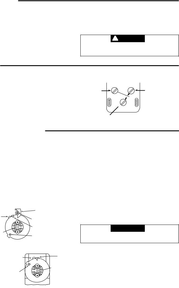
CONVERTIBLE CONTROLS
Convertible controls have a knockout plate on back of case (secured by 2 screws that hold well clamp). To convert from
Horizontal to Vertical:
1.Remove control cover.
2.Loosen 2 clamp screws.
3.Swing capillary down through slot into bottom knockout.
4.Secure knockout plate to back of case by sliding screws through keyhole slots on bottom of case.
CONVERSION ADAPTER
CAPILLARY
BULB
Some controls have excess stored capillary which may be extended for use with an extended shank well. Use reasonable care when straightening and forming the capillary.
EXTENDING CAPILLARY
With the capillary fully extended, the bulb should slide all the way to the end of the well.
|
|
|
|
|
|
WHITE-RODGERS DIVISION |
|
|
|
|
|
|
|
EMERSON ELECTRIC CO. |
|
|
|
|
|
|
|
|
|
|
|
|
|
|
|
9797 REAVIS RD., ST. LOUIS, MO. 63123 |
|
|
|
|
|
|
|
(314) 577-1300, FAX (314) 577-1517 |
Printed in U.S.A. |
|
|
|
|
|
|
||
|
|
|
|
|
|
9999 HWY. 48, MARKHAM, ONT. L3P 3J3 |
|
|
|
|
|
|
|
|
|
|
|
|
|
|
|
(905) 475-4653, FAX (905) 475-4625 |
|
PART NO. 37-2561B
Replaces 37-2561A & 37-9461 9549
INSTALLATION
If the boiler manufacturer recommends a control location, follow such recommendations. If none is offered, the following information gives suggested locations.
When used for high limit service, the control should be installed in the riser close to the boiler, or in a boiler tapping that is near the top or hottest section of the boiler. If the boiler is also used to heat domestic hot water, make sure that the high limit control is not located in the section of the boiler that contains the heat exchanger or piping for domestic hot water.
When used for low limit or operator service, the control should be located near that section of the boiler that contains the heat
exchanger or piping for domestic hot water.
To remove the well from the control, loosen the set screw in the large nut, then slide the well off to expose the bulb. Screw the well into the proper tapping. Slide the bulb back into the well, making sure that the bulb enters the well as far as it will go and tighten the set screw.
 CAUTION
Do not dent or bend the bulb as this will prevent it from fitting into the well properly.
WIRING
All wiring should be done in accordance with local and national electrical codes and ordinances.
11D05 .................... |
CLOSE ON RISE |
11D18 .................... |
OPEN ON RISE |
11D31 .................... |
S.P.D.T. |
11D55 .................... |
OPEN ON RISE (manual reset) |
RED BLUE
OPEN ON RISE
COMMON
OF TEMPERATURE
 WHITE
WHITE
S.P.D.T.
CLOSE ON RISE
OF TEMPERATURE
SETTING THE CONTROL
CONTROLS WITH ADJUSTABLE DIFFERENTIAL
1.Insert a screwdriver in the centre slot and turn the dial until the right hand indicator “B” points to the lowest temperature of the cycle.
2.Turn the differential adjusting screw “C” until the left hand indicator “D” points to the highest temperature of the cycle.
The left-hand indicator points to the temperature at which the contacts open on high limit and low limit applications. On circulator applications, the left-hand indicator points to the temperature at which the circulator will start.
On combination low limit and circulator applications, the left-hand indicator points to the temperature at which the low limit stops the burner and permits the circulator to run.
“B” FIXED INDICATOR (CUT-IN POINT)
“F” STOP TAB
“C” DIFFERENTIAL ADJUSTING SCREW
“D” MOVABLE INDICATOR
(CUT-OUT POINT)
“A” ADJUSTING |
|
SLOT |
“E” STOP SCREW |
ADJUSTABLE DIFFERENTIAL
CONTROLS WITH FIXED DIFFERENTIAL
Insert a screwdriver in centre slot “A” and turn the dial until the fixed indicator “B” points to the highest desired temperature of the cycle.
The fixed indicator points to the temperature at which the contacts open on high limit and low limit applications. On circulator applications, the fixed indicator points to the temperature at which the circulator will start.
On combination low limit and circulator applications, the fixed indicator points to the temperature at which the low limit stops the burner and permits the circulator to run.
CONTROLS WITH ADJUSTABLE STOPS
1.Loosen stop screw (E) with enclosed wrench.
2.Set dial to original equipment manufacturer's specification.
3.Without moving the dial, move stop tab (F) against indicator.
4.Retighten stop screw (E).
 CAUTION
Setting stop higher than control being replaced could cause personal injury and/or property damage.
“F” STOP TAB |
“B” FIXED |
|
INDICATOR |
||
|
“A” ADJUSTING
SLOT
“E” STOP SCREW
FIXED DIFFERENTIAL |
2 |
 Loading...