


WOD77EC0HW

INSTALLATION INSTRUCTIONS 27" (68.6 CM)
AND 30" (76.2 CM) ELECTRIC SINGLE
AND DOUBLE BUILT-IN OVEN
INSTRUCTIONS D’INSTALLATION FOUR
ÉLECTRIQUE ENCASTRÉ 27" (68,6 CM)
ET 30" (76,2 CM) - SIMPLE ET DOUBLE
INSTRUCCIONES DE INSTALACIÓN DEL
HORNO EMPOTRADO ELÉCTRICO SIMPLE
Y DOBLE DE 27" (68,6 CM) Y 30" (76,2 CM)
Table of Contents/Table des matières/Índice
BUILT-IN OVEN SAFETY ......................... 2
INSTALLATION REQUIREMENTS
.......... 2
Tools and Parts
...................................... 2
Location Requirements
......................... 3
Electrical Requirements
........................ 6
INSTALLATION INSTRUCTIONS
............ 7
Prepare Built-In Oven
............................ 7
Remove Oven Door(s)
........................... 7
Replace Oven Door(s)
........................... 8
Positioning Oven Feet for Multiple
Cabinet Cutout Heights ........................ 8
Make Electrical Connection
................ 13
Install Oven
.......................................... 14
Install Warming Drawer Deflector Kit .. 16
Complete Installation
.......................... 16
SÉCURITÉ DU FOUR ENCASTRÉ
....... 17
EXIGENCES D’INSTALLATION
............ 17
Outillage et pièces
............................... 17
Exigences d’emplacement
.................. 18
Spécifications électriques
................... 21
INSTRUCTIONS D’INSTALLATION
...... 22
Préparation du four encastré
.............. 22
Dépose de la/des porte(s) du four
...... 22
Réinstallation la porte(s) du four
......... 23
Positionnement des pieds du four
pour des ouvertures d’encastrement
de hauteur différente ........................... 24
Raccordement électrique
.................... 28
Installation du four
............................... 30
Installation de l’ensemble de
déflecteur du tiroir-réchaud ................31
Achever l’installation
........................... 32
SEGURIDAD DEL
HORNO INTEGRADO ............................ 33
REQUISITOS DE INSTALACIÓN
.......... 33
Herramientas y piezas
......................... 33
Requisitos de ubicación
...................... 34
Requisitos eléctricos
........................... 37
INSTRUCCIONES DE INSTALACIÓN
.. 38
Prepare el horno integrado
................. 38
Retire la puerta del horno
.................... 38
Vuelva a colocar la puerta del horno
.. 39
Ubicación de las patas del
horno para múltiples alturas
de corte del armario ............................ 39
Haga la conexión del
suministro eléctrico ............................. 44
Instale el horno
.................................... 45
Instale el kit de deflector
para cajón de calentamiento .............. 47
Finalización de la instalación
.............. 47
IMPORT
ANT:
Save for local electrical inspector’s use.
IMPORTANT :
À conserver pour consultation par l’inspecteur local des installations électriques.
IMPORTANTE:
Guarde para tener a disposición del inspector de electricidad local.
W11129956
A
2
BUILT-IN OVEN SAFETY
INSTALLATION REQUIREMENTS
Tools and Parts
Gather the required tools and parts before starting
installation. Read and follow the instructions provided
with any tools listed here.
Tools Needed
■ Phillips screwdriver
■ Measuring tape
■ Hand or electric drill (for wall cabinet installations)
■ 1” (2.5 cm) drill bit (for wall cabinet installations)
■ Level
■ Flat-blade screwdriver
Parts Needed
■ UL Listed or CSA Approved conduit connector
■ UL Listed wire connectors
■ Warming Drawer Deflector Kit (for ovens installed above a
warming drawer):
Color Size Type Warming Drawer
Deflector Kit
White 27” Single / Double W10510613
White 30” Single / Double W10510614
Black 27” Single / Double W10531009
Black 30” Single / Double W10531010
SS 27” Single / Double W10536338
SS 30” Single / Double W10536339
BSS 27” Single / Double W10888988
BSS 30” Single / Double W10727416
Bronze 30” Single / Double W11123007
To order, see the “Assistance or Service” section of the Use and
Care Guide.
■ Flush Installation Kit (for Single and Double installed at flush
installation):
Color Size Type Flush Installation
Kit
White 27” Single / Double W11173681
White 30” Single / Double W11173683
Black 27” Single / Double W11173685
Black 30” Single / Double W11173691
SS 27” Single / Double W11173693
SS 30” Single / Double W11123003
BSS 27” Single / Double W11173700
BSS 30” Single / Double W11173703
Bronze 30” Single / Double W11123005
To order, see the “Assistance or Service” section of the Use and
Care Guide.
Parts Supplied
■ #8-14 x 3/4” (19 mm) screws: single ovens (2), double ovens
(4)
■ #8-18 x 3/8” (9.5 mm) screws: bottom vent (2)
■ #8-18 x 1/4” (6.4 mm) screws: bottom vent trim (4)
■ #8-18 x 3/8” (9.5 mm) screws: double oven feet (4)
■ Bottom vent
■ Bottom vent trim
■ Rear feet: double oven (2)
■ Front feet: double oven (2)
Check local codes. Check existing electrical supply. See the
“Electrical Requirements” section.
It is required that all electrical connections be made by a
licensed, qualified electrical installer.
You can be killed or seriously injured if you don't immediately
You
can be killed or seriously injured if you don't
follow
All safety messages will tell you what the potential hazard is, tell you how to reduce the chance of injury, and tell you what can
happen if the instructions are not followed.
Your safety and the safety of others are very important.
We have provided many important safety messages in this manual and on your appliance. Always read and obey all safety
messages.
This is the safety alert symbol.
This symbol alerts you to potential hazards that can kill or hurt you and others.
All safety messages will follow the safety alert symbol and either the word “DANGER” or “WARNING.”
These words mean:
follow instructions.
instructions.
DANGER
WARNING
3
Location Requirements
IMPORTANT: Observe all governing codes and ordinances.
■ Cabinet opening dimensions that are shown must be used.
Given dimensions provide minimum clearance with oven.
■ Recessed installation area must provide complete
enclosure around the recessed portion of the oven.
■ Grounded electrical supply is required. See the
“Electrical Requirements” section.
■ Electrical supply junction box should be located 3" (7.6 cm)
above the cutout or 3" (7.6 cm) maximum below the support
surface when the oven is installed in a wall cabinet. A
1" (2.5 cm) minimum diameter hole should have been drilled
in the right rear or left rear corner of the upper or lower
support surface to pass the appliance cable through to the
junction box.
NOTE: For undercounter installation, it is recommended
that the junction box be located in the adjacent right or
left cabinet. If you are installing the junction box on rear
wall behind oven, it is recommended that the junction box
be recessed and located in the upper center of the cabinet.
■ Oven support surface must be solid, level, and flush
with bottom of cabinet cutout.
■ Floor must be able to support a single oven weight of 129 lbs
(59 kg) for 27" (68.6 cm) models or 154 lbs (70 kg) for 30"
(76.2 cm) models.
■ Floor must be able to support a double oven weight of
251 lbs (114 kg) for 27" (68.6 cm) models or 288 lbs (131 kg)
for 30" (76.2 cm) models.
IMPORTANT: To avoid damage to your cabinets, check
with your builder or cabinet supplier to make sure that the
materials used will not discolor, delaminate, or sustain other
damage. This oven has been designed in accordance with
the requirements of UL and CSA International and complies
with the maximum allowable wood cabinet temperatures
of 194°F (90°C).
Undercounter Installation (with Cooktop Installed Above):
Refer to the Cutout Dimensions for Ovens Installed Under
Cooktop (separate sheet). See product website for list of
cooktop models approved for use above select wall-oven
models.
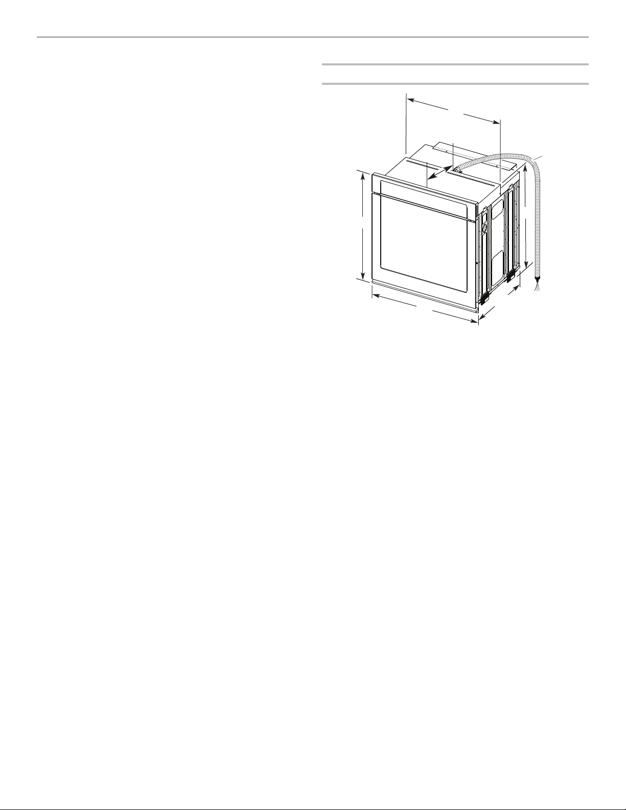
Product Dimensions — Single Ovens
B
C
D
E
A
G
F
27" (68.6 cm) models
A. 28
3
/
4
" (72.8 cm) max.
overall height
B. 25
7
/
16
" (64.6 cm) max.
recessed width
C. 26
3
/
4
" (67.9 cm)
recessed height
D. 23
1
/
4
" (59.1 cm) max.
recessed depth
E. 27" (68.6 cm) overall width
F. 12" (30.5 cm) from back
of control panel to start
of strain relief
G. 48" (121.9 cm) flexible
conduit length
30" (76.2 cm) models
A. 28
3
/
4
" (72.8 cm) max.
overall height
B. 28
1
/
2
" (72.4 cm) max.
recessed width
C. 26
3
/
4
" (67.9 cm)
recessed height
D. 23
1
/
4
" (59.1 cm) max.
recessed depth
E. 30" (76.2 cm) overall width
F. 12" (30.5 cm) from back
of control panel to start
of strain relief
G. 48" (121.9 cm) flexible
conduit length
4
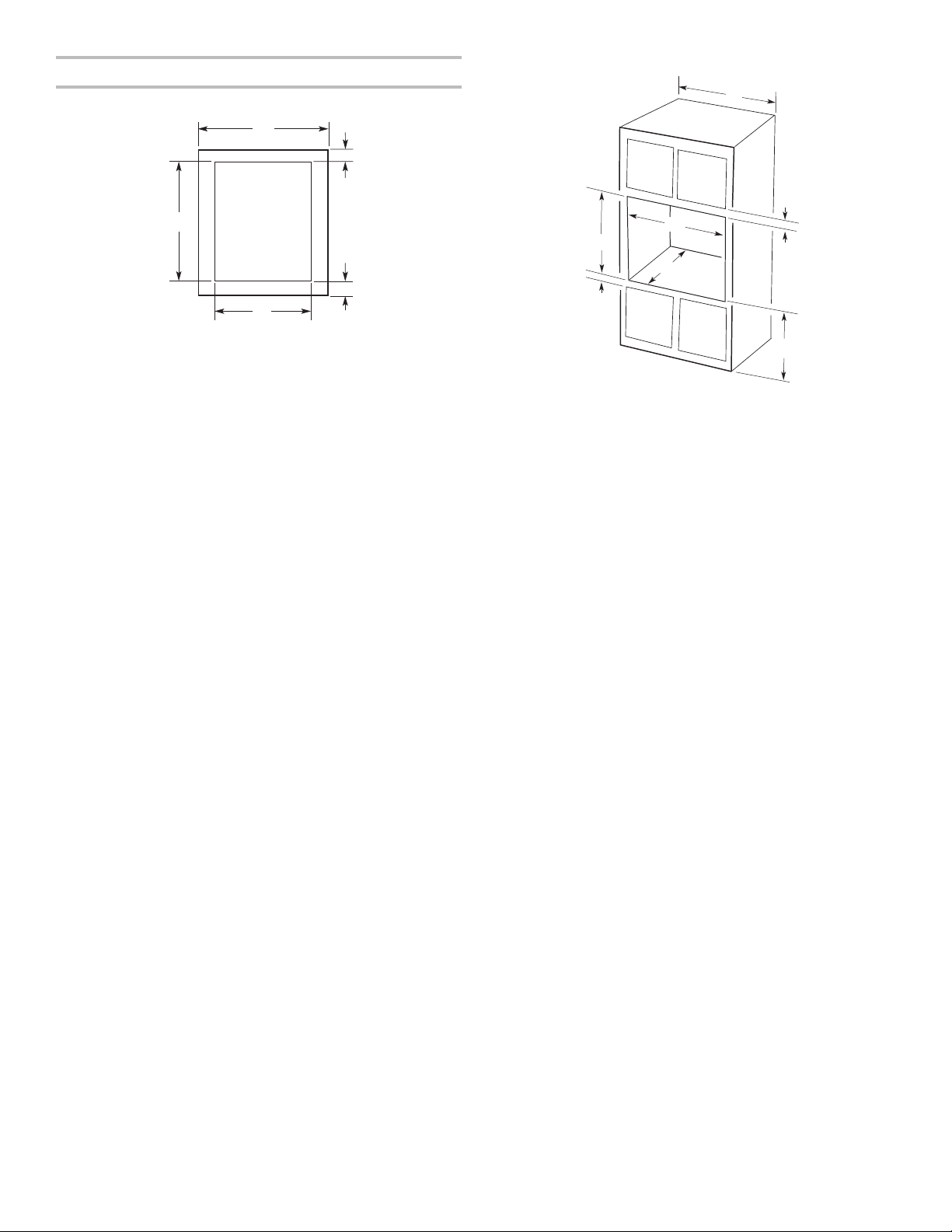
Cabinet Dimensions — Single Ovens
Single Oven Undercounter (Without Cooktop Installed Above)
Single Ovens Installed in Cabinet
*NOTE: The cutout height can be between 26
15
/
16
" and 29
7
/
16
"
(68.4 cm and 74.8 cm) for single ovens.
A
B
C
D
E
27" (68.6 cm) models
A. 27" (68.6 cm) min.
cabinet width
B. 1
1
/
2
" (3.8 cm) min. top
of cutout to underside
of countertop
C. 5
1
/
4
" (13.3 cm) bottom
of cutout to floor
D. 25
1
/
2
" (64.8 cm)
cutout width
E. 28" (71.2 cm) min.
cutout height
30" (76.2 cm) models
A. 30" (76.2 cm) min.
cabinet width
B. 1
1
/
2
" (3.8 cm) min. top
of cutout to underside
of countertop
C. 5
1
/
4
" (13.3 cm) bottom
of cutout to floor
D. 28
1
/
2
" (72.4 cm)
cutout width
E. 28" (71.2 cm) min.
cutout height
F
E
B
C
A
D
G
27" (68.6 cm) models
A. 27" (68.6 cm) min.
cabinet width
B. 1" (2.5 cm) top of
cutout to bottom of
upper cabinet door
C. 32" (81.3 cm) bottom
of cutout to floor
D. 25
1
/
2
" (64.8 cm)
cutout width
E. 1
1
/
2
" (3.8 cm) min.
bottom of cutout to
top of cabinet door
F. 28" (71.2 cm)*
recommended
cutout height
G. 24" (60.7 cm) cutout
depth
30" (76.2 cm) models
A. 30" (76.2 cm) min.
cabinet width
B. 1" (2.5 cm) top of
cutout to bottom of
upper cabinet door
C. 32" (81.3 cm) bottom of
cutout to floor
D. 28
1
/
2
" (72.4 cm)
cutout width
E. 1
1
/
2
" (3.8 cm) min.
bottom of cutout to
top of cabinet door
F. 28" (71.2 cm)*
recommended
cutout height
G. 24" (60.7 cm) cutout
depth
5
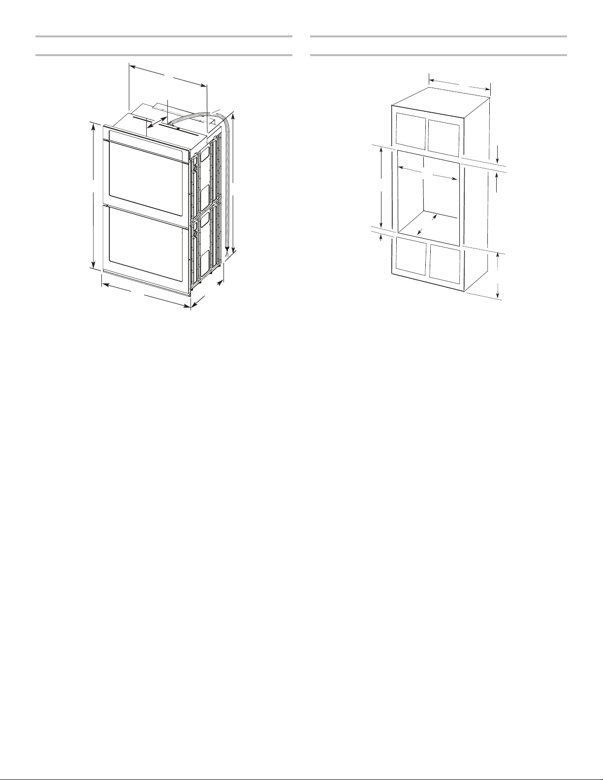
Product Dimensions — Double Ovens Cabinet Dimensions — Double Ovens
Double Ovens Installed in Cabinet
*NOTE: The cutout height can be between 48
7
/
8
" and 52
3
/
16
"
(124.1 cm and 132.6 cm) for double ovens.
C
A
E
D
B
F
G
27" (68.6 cm) models
A. 51
3
/
16
" (130.0 cm)
max. overall height
B. 25
7
/
16
" (64.6 cm)
max. recessed width
C. 48
13
/
16
" (124.0 cm)
recessed height
D. 23
1
/
4
" (59.1 cm) max.
recessed depth
E. 27" (68.6 cm) overall width
F. 12" (30.5 cm) from back
of control panel to start
of strain relief
G. 66" (167.6 cm) flexible
conduit length
30" (76.2 cm) models
A. 51
3
/
16
" (130.0 cm) max.
overall height
B. 28
1
/
2
" (72.4 cm) max.
recessed width
C. 48
13
/
16
" (124.0 cm)
recessed height
D. 23
1
/
4
" (59.1 cm) max.
recessed depth
E. 30" (76.2 cm) overall width
F. 12" (30.5 cm) from back
of control panel to start
of strain relief
G. 66" (167.6 cm) flexible
conduit length
F
E
A
D
G
B
C
27" (68.6 cm) models
A. 27" (68.6 cm) min.
cabinet width
B. 1" (2.5 cm) top of
cutout to bottom of
upper cabinet door
C. 14
3
/
4
" (37.5 cm) bottom
of cutout to floor is
recommended.
4-14
3
/
4
" (10.2-37.5 cm)
bottom of cutout to floor
is acceptable.
D. 25
1
/
2
" (64.8 cm)
cutout width
E. 1
1
/
2
" (3.8 cm) min.
bottom of cutout to
top of cabinet door
F. 50
1
/
4
" (127.6 cm)*
recommended cutout height
G. 24" (60.7 cm) cutout depth
30" (76.2 cm) models
A. 30" (76.2 cm) min.
cabinet width
B. 1" (2.5 cm) top of
cutout to bottom of
upper cabinet door
C. 14
3
/
4
" (37.5 cm) bottom
of cutout to floor is
recommended.
4-14
3
/
4
" (10.2-37.5 cm)
bottom of cutout to floor is
acceptable.
D. 28
1
/
2
" (72.4 cm)
cutout width
E. 1
1
/
2
" (3.8 cm) min.
bottom of cutout to
top of cabinet door
F. 50
1
/
4
" (127.6 cm)*
recommended cutout height
G. 24" (60.7 cm) cutout depth
6
Electrical Requirements
If codes permit and a separate ground wire is used, it is
recommended that a qualified electrical installer determine that
the ground path and the wire gauge are in accordance with local
codes.
Check with a qualified electrical installer if you are not sure the
oven is properly grounded.
This oven must be connected to a grounded metal, permanent
wiring system.
Be sure that the electrical connection and wire size are
adequate and in conformance with the National Electrical Code,
ANSI/NFPA 70 — latest edition or CSA Standards C22.
1-94, Canadian Electrical Code, Part 1 and C22.2 No.
O-M91 — latest edition, and all local codes and ordinances.
A copy of the above code standards can be obtained from:
National Fire Protection Association
1 Batterymarch Park
Quincy, MA 02169-7471
CSA International
8501 East Pleasant Valley Road
Cleveland, OH 44131-5575
Electrical Connection
To properly install your oven, you must determine the type of
electrical connection you will be using and follow the instructions
provided for it here.
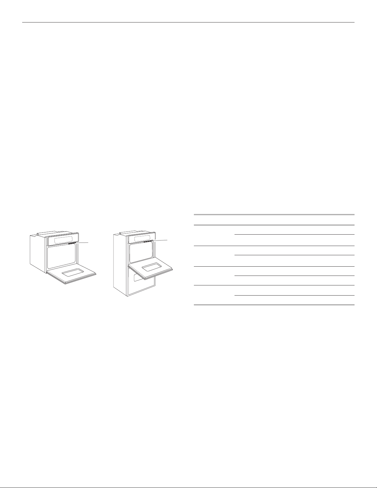
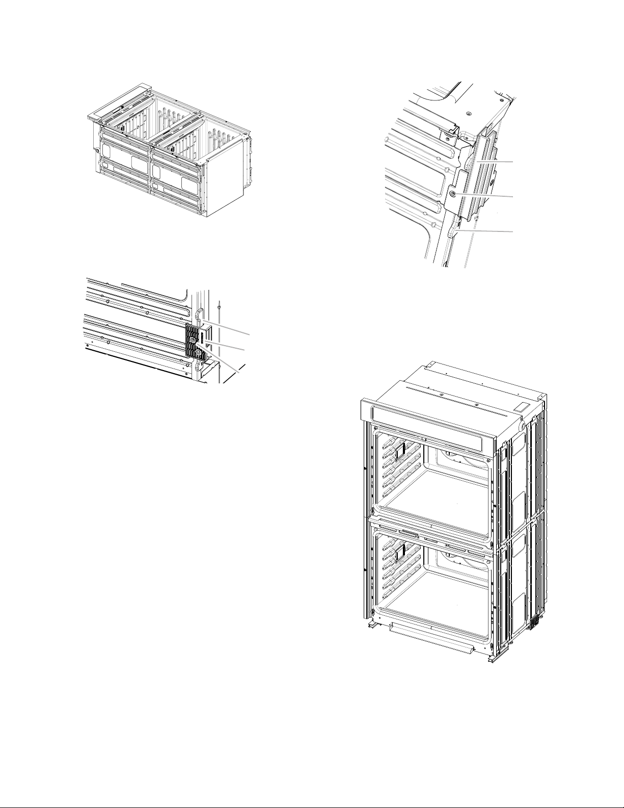
■ Oven must be connected to the proper electrical voltage and
frequency as specified on the model/serial/rating plate. The
model/serial/rating plate is located under the control panel
on single ovens and under the control panel on the upper
oven cavity on double ovens. See the following illustrations.
■ Models rated from 7.3 to 9.6 kW at 240 volts (6.3 to 8.3 kW
at 208 volts) require a separate 40-amp circuit. Models
rated from 4.9 to 7.2 kW at 240 volts (4.3 to 6.2 kW at
208 volts) require a separate 30-amp circuit. Models rated at
4.8 kW and below at 240 volts (4.2 kW and below at
208 volts) require a separate 20-amp circuit.
■ A circuit breaker is recommended.
■ Connect directly to the circuit breaker box (or fused
disconnect) through flexible, armored, or nonmetallic
sheathed, copper cable (with grounding wire). See the “Make
Electrical Connection” section.
■ Flexible conduit from the oven should be connected directly
to the junction box.
■ Fuse both sides of the line.
■ Do not cut the conduit. The length of conduit provided is for
serviceability of the oven.
■ A UL Listed or CSA Approved conduit connector must be
provided.
■ If the house has aluminum wiring, follow the procedure
below:
Connect the aluminum wiring using special connectors
and/or tools designed and UL Listed for joining copper to
aluminum.
Follow the electrical connector manufacturer’s recommended
procedure. Aluminum/copper connection must conform with
local codes and industry accepted wiring practices.
Series Voltage Frequency Rating
WOD97EC/
WODA7EC/
WOD77EC
120/240 V AC 60 Hz 8 kW
120/208 V AC 60 Hz 6 kW
WOS97EC/
WOSA2EC/
WOS72EC
120/240 V AC 60 Hz 4 kW
120/208 V AC 60 Hz 3 kW
WOD51EC 120/240 V AC 60 Hz 7.6 kW
120/208 V AC 60 Hz 5.7 kW
WOS51EC 120/240 V AC 60 Hz 3.9 kW
120/208 V AC 60 Hz 2.9 kW
A
A
Single Oven
A. Model/serial/rating plate
Double Oven
A. Model/serial/rating plate
7
INSTALLATION INSTRUCTIONS
Prepare Built-In Oven
1. Decide on the final location for the oven. Avoid drilling
or cutting into house wiring during installation.
2. To avoid floor damage, set the oven onto cardboard prior
to installation. Do not use handle or any portion of the front
frame for lifting.
3. Remove the shipping materials and tape from the oven.
Remember to keep the corner posts and other materials
that may be needed for installation.
4. Remove the hardware package from inside the bag
containing literature.
5. Remove and set aside racks and other parts from
inside the oven.
6. Move oven and cardboard close to the oven’s final location.
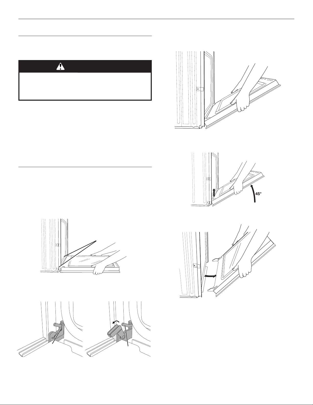
Remove Oven Door(s)
IMPORTANT: Use two hands to remove oven door. For double
ovens, repeat the process for each door.
1. Prior to removing the oven door, prepare a surface where
you will place it. This surface should be flat and covered
with a soft blanket, or use the corner posts from your
packaging material.
2. Fully open the oven door.
3. Locate the oven door hinge locks in both corners of the
oven door, and rotate the hinge locks toward the oven door
to the unlocked position. If the door hinge lock is not rotated
fully (see illustration B), the door will not remove properly.
4. Gently start to close the door. The door will stop at a partially
closed position.
5. Using two hands, grasp the edges of the oven door. Close
the oven door slightly past the stop position to take the
weight off of the door hinges, and then pull the oven door up.
6. Pull the oven door toward you, and then remove. You may
need to gently shift the door from side to side as you pull.
7. Set the oven door aside on the prepared covered work
surface with the oven door resting on its handle.
8. To continue with the oven installation, go to the
“Positioning Oven Feet for Multiple Cabinet Cutout
Heights” section.
WARNING
Excessive Weight Hazard
Use two or more people to move and install oven.
Failure to do so can result in back or other injury.
Door
hinges
Locked
position
Grip here
to rotate.
Unlocked
position
A. Oven door hinge lock in
locked position
B. Oven door hinge lock in
partially unlocked position
Soft close hinge
arm on select models

8
Replace Oven Door(s)
1. Using two hands, grasp side edges of door at the midpoint.
Face the oven cavity.
2. Locate the slots on each side of the oven front frame for
the door hinge locks.
3. Using two hands, grasp the edges of the oven door. At a 45°
angle, insert the hinges at the same time, and push the oven
door into the oven cavity slot to replace. You may need to
gently shift the door from side to side as you push.
4. Make sure the door hinge notch is engaged on the bottom
of the oven cavity slot.
IMPORTANT: Do not close the door at this step or damage
may occur to the door hinge.
5. Lower the oven door to the fully open position. If the oven
door does not open to a full 90°, repeat steps 1 through 3.
6. Locate the oven door hinge locks in the corners of the oven
door, and rotate the hinge locks toward the oven cavity to
the locked position.
7. After the door hinges have been locked, gently swing the
door upward to close. The door should not be forced closed.
8. When the hinges are properly installed and the door is
closed, there should be an even gap between the door and
the control panel. If one side of the oven door is lower than
the other, the hinge on that side is not properly installed.
See the “Remove Oven Door(s)” and “Replace Oven Door(s)”
sections.
Positioning Oven Feet for Multiple
Cabinet Cutout Heights
Single Ovens
The positioning of the oven feet allow a single oven to be
installed in a cutout height between 26
15
/
16
" and 29
7
/
16
"
(68.4 cm and 74.8 cm). Refer to the following instructions
to position the feet for the size of your cabinet cutout.
Cutout Height Is Between 27
5
/
8
" and 28
5
/
8
"
(70.2 cm and 72.7 cm)
The oven feet do not need to be changed. They are
positioned correctly as received.
Go to the “Make Electrical Connection” section.
A
A. Slot in the oven cavity for door hinge lock
Unlocked
position
Locked
position
Soft close hinge
arm on select models
9
Cutout Height Is Between 26
15
/
16
" and 27
11
/
16
"
(68.4 cm and 70.3 cm)
1. Using two or more people, place the oven on its back
on a covered surface.
2. Remove the foot from the right front spacer by removing
the #8-18 x 3/8" (9.5 mm) screw.
NOTE: Do not remove the spacer.
3. In the same manner, remove the feet on the right rear,
left front, and left rear of the oven.
4. Using two or more people, place the oven in its upright
position.
5. Go to the “Make Electrical Connection” section.
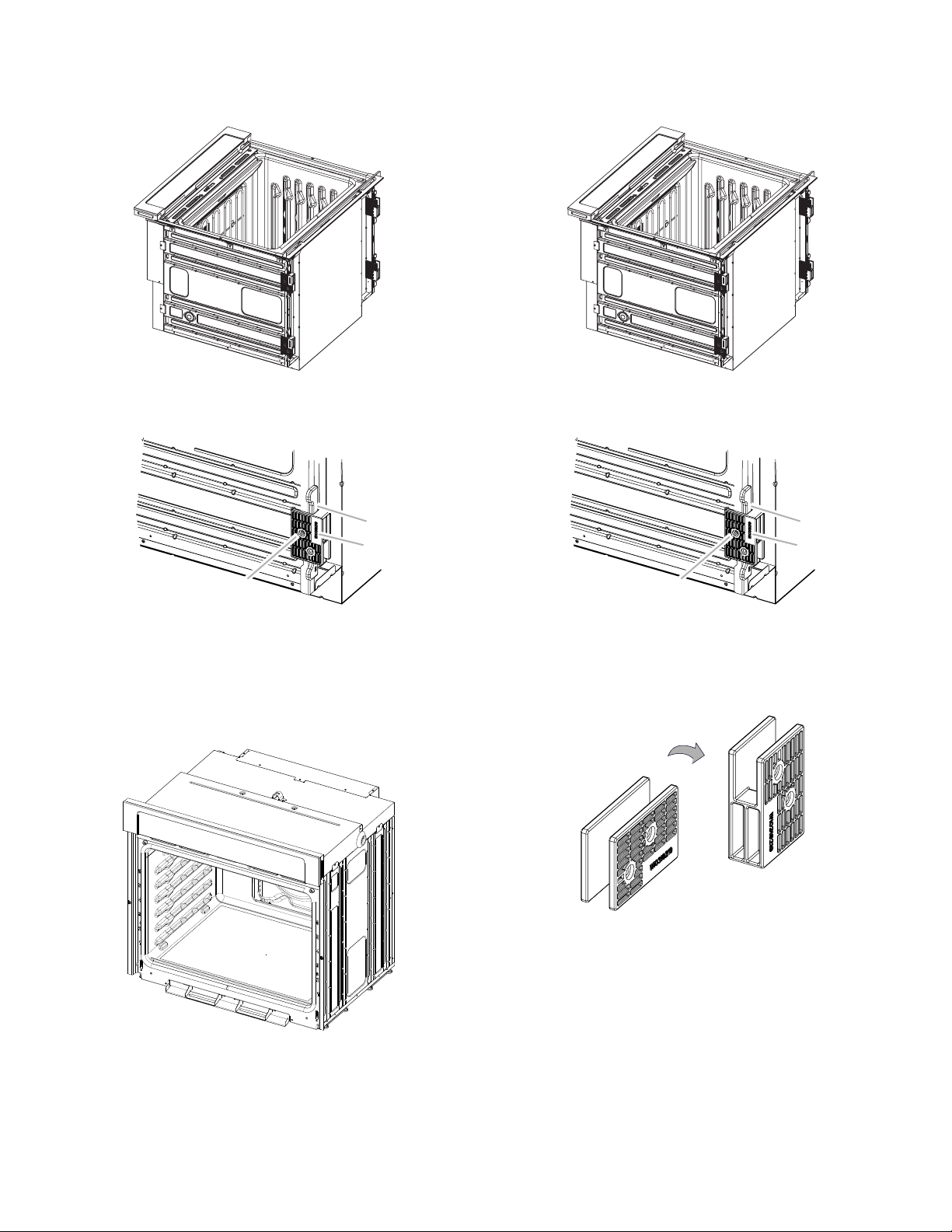
Cutout Height Is Between 28
11
/
16
" and 29
7
/
16
"
(72.8 cm and 74.8 cm)
1. Using two or more people, place the oven on its back
on a covered surface.
2. Remove the foot from the right front spacer by removing
the #8-18 x 3/8" (9.5 mm) screw.
NOTE: Do not remove the spacer.
3. Rotate the foot 90°, so the short side of the foot
is positioned toward the top of the oven.
A
B
C
A. Spacer
B. Foot
C. #8-18 x 3/8" (9.5 mm) screw
A
B
C
A. Spacer
B. Foot
C. #8-18 x 3/8" (9.5 mm) screw
10
4. Reinstall the foot to the spacer using the #8-18 x 3/8"
(9.5 mm) screw previously removed.
5. In the same manner, remove, rotate, and reinstall the
feet on the right rear, left front, and left rear of the oven.
6. Using two or more people, place the oven in its upright
position.
7. Go to the “Make Electrical Connection” section.
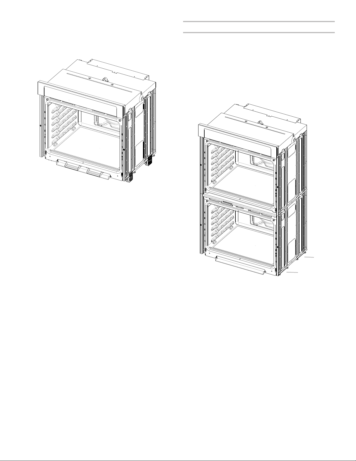
Double Ovens
The positioning of the oven feet allow a double oven to be
installed in a cutout height between 48
7
/
8
" and 52
3
/
16
" (124.1 cm
and 132.6 cm). Refer to the following instructions to position
the feet for the size of your cabinet cutout.
Cutout Height Is Between 48
7
/
8
" and 50
7
/
16
"
(124.1 cm and 128.1 cm)
The oven feet do not need to be installed. The oven
is configured correctly as received.
NOTE: Do not remove the spacers.
Go to the “Make Electrical Connection” section.
A
A
A. Spacers
11
Cutout Height Is Between 50
1
/
2
" and 51
1
/
8
"
(128.2 cm and 129.9 cm)
1. Using two or more people, place the oven on its back
on a covered surface.
2. Install a foot on the left rear spacer using a #8-18 x 3/8"
(9.5 mm) screw.
NOTE: Position the foot so the long side of the foot is facing
toward the top of the oven.
3. In the same manner, install a foot on the right rear of the oven.
4. Install a front foot on the left front spacer using a #8-18 x
3/8" (9.5 mm) screw.
NOTE: Position the foot so the long side of the foot is facing
toward the inside of the oven.
5. In the same manner, install a front foot on the right front
of the oven.
6. Using two or more people, place the oven in its upright
position.
7. Go to the “Make Electrical Connection” section.
A
B
C
A. Spacer
B. Foot
C. #8-18 x 3/8" (9.5 mm) screw
A
B
C
A. Front foot
B. #8-18 x 3/8" (9.5 mm) screw
C. Spacer

12
Cutout Height Is Between 51
3
/
16
" and 52
3
/
16
"
(130 cm and 132.6 cm)
1. Using two or more people, place the oven on its back
on a covered surface.
2. Install a foot on the left rear spacer using a #8-18 x 3/8"
(9.5 mm) screw.
NOTE: Position the foot so the short side of the foot is facing
toward the top of the oven.
3. In the same manner, install a foot on the right rear of the oven.
4. Install a front foot on the left front using a #8-18 x 3/8"
(9.5 mm) screw.
NOTE: Position the foot so the long side of the foot is facing
toward the top of the oven.
5. In the same manner, install a front foot on the right front
of the oven.
6. Using two or more people, place the oven in its upright
position.
7. Go to the “Make Electrical Connection” section.
C
B
A
A. Spacer
B. Foot
C. #8-18 x 3/8" (9.5 mm) screw
A
B
C
A. Front foot
B. #8-18 x 3/8" (9.5 mm) screw
C. Spacer
13
Make Electrical Connection
For Double Ovens For Single Ovens
This oven is manufactured with a neutral (white) power
supply wire and a cabinet-connected green (or bare)
ground wire twisted together.
1. Disconnect power.
2. Feed the flexible conduit from the oven through
the opening in the cabinet.
3. Remove junction box cover if it is present.
4. Install a UL Listed or CSA Approved conduit connector
to the junction box.
5. Route the flexible conduit from the oven to the junction box
through a UL Listed or CSA Approved conduit connector.
6. Tighten screws on conduit connector.
7. See the “Electrical Connection Options Chart” to complete
installation for your type of electrical connection.
Electrical Connection Options Chart
If your home has: Go to section:
4-wire 4-Wire Cable from Home
Power Supply
3-wire 3-Wire Cable from Home
Power Supply
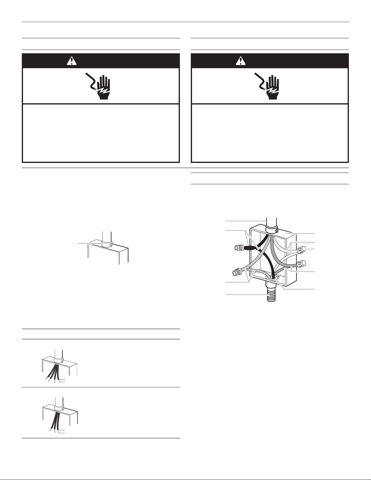
4-Wire Cable from Home Power Supply
IMPORTANT: Use the 4-wire cable from home power
supply in the U.S. where local codes do not allow grounding
through neutral, New Branch circuit installations (1996 NEC),
mobile homes and recreational vehicles, new construction,
and in Canada.
1. Connect the two black wires (B) together using
a UL Listed wire connector.
2. Connect the two red wires (C) together using
a UL Listed wire connector.
3. Untwist white wire from green (or bare)
ground wire coming from the oven.
4. Connect the two white wires (F) together using
a UL Listed wire connector.
5. Connect the green (or bare) ground wire (H) from
the oven cable to the green (or bare) ground wire
(in the junction box) using a UL Listed wire connector.
6. Install junction box cover.
WARNING
Electrical Shock Hazard
Disconnect power before servicing.
Use 8 gauge copper wire.
Electrically ground oven.
Failure to follow these instructions can result in death,
fire, or electrical shock.
WARNING
Electrical Shock Hazard
Disconnect power before servicing.
Use 12 gauge copper wire.
Electrically ground oven.
Failure to follow these instructions can result in death,
fire, or electrical shock.
A
A. UL Listed or CSA Approved conduit connector
½"
(1.3 cm)
½"
(1.3 cm)
A
D
F
H
B
C
E
G
I
A. Cable from home power supply
B. Black wires
C. Red wires
D. 4-wire flexible conduit
from oven
E. Junction box
F. White wires
G. UL Listed wire connectors
H. Green (or bare) ground wires
I. UL Listed or CSA Approved
conduit connector
14
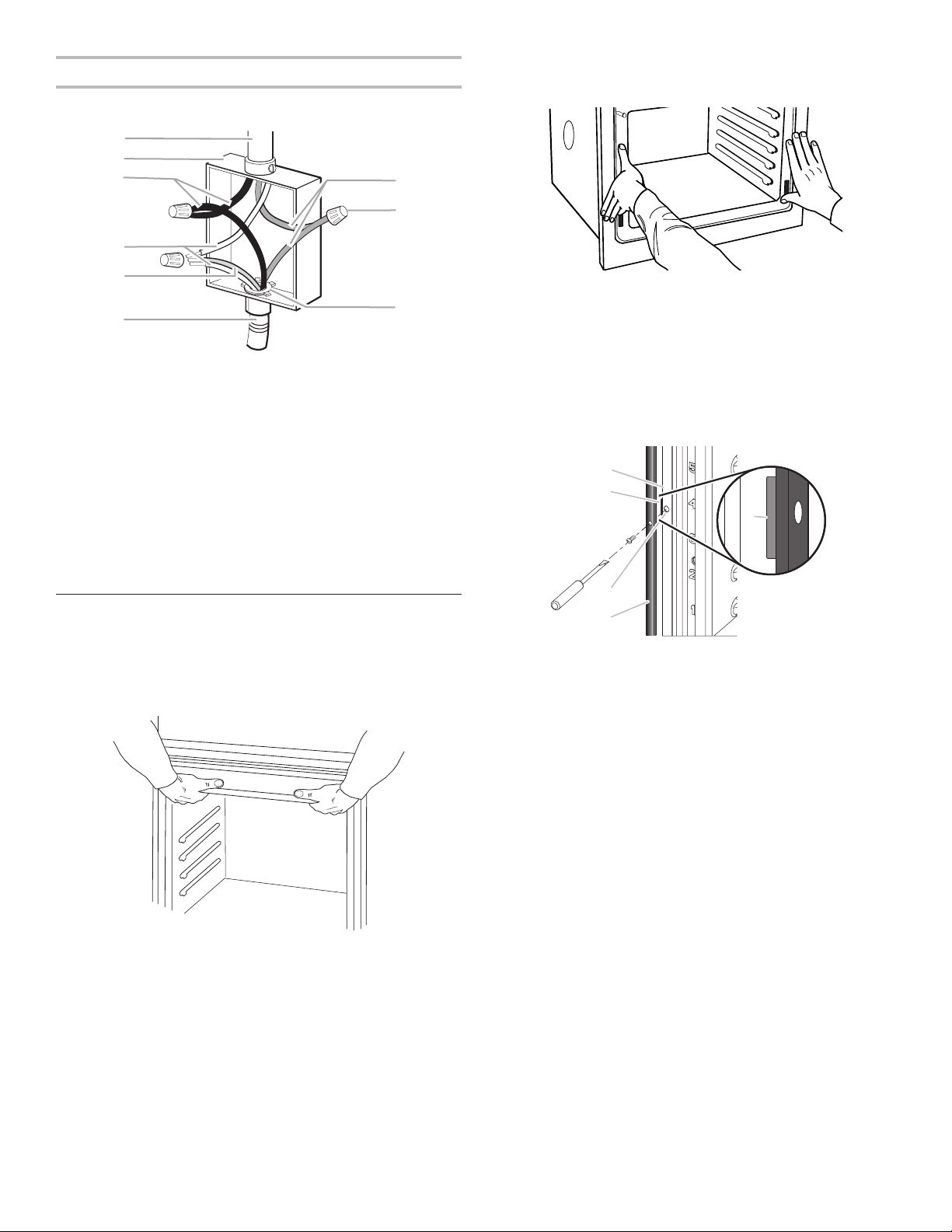
3-Wire Cable from Home Power Supply: U.S. Only
IMPORTANT: Use the 3-wire cable from home power
supply where local codes permit a 3-wire connection.
1. Connect the two black wires (C) together using
a UL Listed wire connector.
2. Connect the two white wires (D) and the green (or bare)
ground wire (of the oven cable) using a UL Listed wire
connector.
3. Connect the two red wires (G) together using
a UL Listed wire connector.
4. Install junction box cover.
Install Oven
1. Using two or more people, lift the oven partially into the
cabinet cutout. Use the oven opening as an area to grip.
NOTE: Push against seal area of the oven front frame when
pushing the oven into the cabinet. Do not push against the
outside edges.
2. Push against the seal area of the front frame to push
the oven into the cabinet until the back surface of the
front frame touches the front wall of the cabinet.
3. Push oven completely into the cabinet and center
the oven into the cabinet cutout.
4. Remove the tape from the black front trim, and remove
the zip tie from the mounting spacer.
■ Securely fasten the oven to the cabinet using the
#8-14 x 1" (2.5 cm) screws provided.
■ Insert the screws through holes in black trim, aligning
with the holes in oven frame and mounting spacers
already in place. Do not overtighten screws.
B
C
D
E
F
H
G
A
I
A. Cable from home power supply
B. Junction box
C. Black wires
D. White wires
E. Green (or bare) ground
wire (from oven)
F. 4-wire flexible conduit
from oven
G. Red wires
H. UL Listed wire connectors
I. UL Listed or CSA Approved
conduit connector
A
C
D
B
B
A. Oven frame
B. Mounting spacer
C. Oven frame hole
D. Black trim piece
15
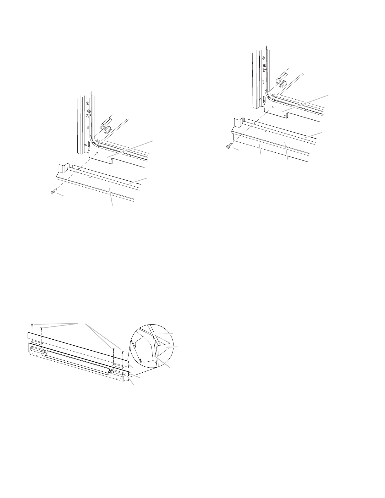
5. The bottom vent and bottom vent trim (required when
the oven is installed with the feet in the tall position)
are shipped in the foam packing at the top of the oven.
To install only the bottom vent, see the following instructions.
To install both the bottom vent and the bottom vent trim
for installations with the feet in the tall position, see the
instructions in Step 6.
■ Align vent tab (B) with oven frame (A) as shown.
■ Using one #8-18 x 3/8" (9.5 mm) screw (D) on each side
of the vent tab (B), fasten the vent securely to the oven.
6. On models with the feet installed in the tall position, the
bottom vent trim must also be installed. See the following
instructions to install.
■ Flex the upper vent piece (C) away from the lower vent
piece (D) to slide the bottom vent trim (B) between them.
Some force may be required to flex the upper vent trim (C)
away from the lower vent trim (D). Some force may also
be required to flex the bottom vent trim (B) and slide it
into position. Make sure screw holes are properly aligned
between the two pieces. See the following illustration.
■ Install the bottom vent trim (B) to the lower vent piece (D)
using two #8-18 x 1/4" (6.4 mm) screws on each side.
■ Align vent tab (B) with oven frame (A) as shown.
■ Using one #8-18 x 3/8" (9.5 mm) screw (E) on each side
of the vent tab (B), fasten the vent securely to the oven.
7. Replace the oven racks.
8. Replace the oven door. See the “Replace Oven
Door(s)” section.
9. Check that the door is free to open and close. If it is not,
repeat the removal and installation procedures. See the
“Prepare Built-In Oven” section.
10. Repeat for lower oven door.
11. Reconnect power.
12. The display panel will light briefly, and “PF” should
appear in the display.
13. If the display panel does not light, reference the
“Warranty” section of the Use and Care Guide.
A
C
D
B
A. Oven frame
B. Vent tab
C. Oven vent
D. #8-18 x 3/8"
(9.5 mm) screws
D
B
A
C
B
D
C
A. #8-18 x 1/4"
(6.4 mm) screw
B. Bottom vent trim
C. Upper vent piece
D. Lower vent piece
A
C
D
B
E
A. Oven frame
B. Vent tab
C. Oven vent
D. Bottom vent trim
E. #8-18 x 3/8"
(9.5 mm) screw
 Loading...