


 Loading...
Multimedia
Enhanced
SERVICE MANUAL
Whirlpool® Smart Wall Ovens
Model No.: WOC54EC0H WOC54EC7H WOC75EC0H
WOC75EC7H WOC97EC0H WOCA7EC0H
WOD51EC0H WOD51EC7H WOD77EC0H
WOD77EC7H WOD97EC0H WODA7EC0H
WOS51EC0H WOS51EC7H WOS72EC0H
WOS72EC7H WOS97EC0H WOSA2EC0H
W11174422

FORWARD
This Whirlpool Service Manual, (Part No. W11174422), provides the In-Home Service Professional with service information for the “Whripool® Smart Wall Ovens”.
The Wiring Diagram used in this Service Manual is typical and should be used for training purposes only. Always use the Wiring Diagram supplied with the product tech sheet when servicing the oven.
For specific operating and installation information on the model being serviced, refer to the “Use and Care Guide” or “Installation Instructions” provided with the oven.
GOALS AND OBJECTIVES
The goal of this Service Manual is to provide information that will enable the In-Home Service Professional to properly diagnose malfunctions and repair the “Whripool® Smart Wall Ovens”.
The objectives of this Service Manual are to:
•Understand and follow proper safety precautions.
•Successfully troubleshoot and diagnose malfunctions.
•Successfully perform necessary repairs.
WHIRLPOOL CORPORATION assumes no responsibility for any repairs made on our products by anyone other than authorized In-Home Service Professionals.
©2018 Whirlpool Corporation. Benton Harbor, MI 49022
ii n Whirlpool® Smart Wall Ovens

TABLE OF CONTENTS
Whirlpool® Smart Wall Ovens
SECTION 1: GENERAL INFORMATION......................................................................... |
1-1 |
OVEN SAFETY....................................................................................................................................... |
1-2 |
PRODUCT SPECIFICATIONS................................................................................................................. |
1-3 |
PRODUCT FEATURES........................................................................................................................... |
1-8 |
MODEL & SERIAL NUMBER LOCATION............................................................................................. |
1-11 |
MODEL & SERIAL NUMBER NOMENCLATURE.................................................................................. |
1-12 |
TECH SHEET LOCATION...................................................................................................................... |
1-13 |
SECTION 2: DIAGNOSTICS........................................................................................... |
2-1 |
SAFETY................................................................................................................................................. |
2-2 |
DIAGNOSTICS MODE........................................................................................................................... |
2-3 |
FAILURE/ERROR DISPLAY CODES ....................................................................................................... |
2-5 |
SECTION3:COMPONENT TESTING............................................................................. |
3-1 |
SAFETY................................................................................................................................................. |
3-2 |
WIRING DIAGRAM.............................................................................................................................. |
3-3 |
COMPONENT TESTING...................................................................................................................... |
3-13 |
COMPONENT LOCATION................................................................................................................... |
3-15 |
SECTION 4: COMPONENT ACCESS............................................................................... |
4-1 |
REMOVING THE MICROWAVE HMI..................................................................................................... |
4-2 |
ACCESSING THE MICROWAVE APPLIANCE MANAGER....................................................................... |
4-3 |
ACCESSING THE MICROWAVE INVERTER BOARD............................................................................... |
4-5 |
ACCESSING THE MICROWAVE MAGNETRON...................................................................................... |
4-6 |
REMOVING THE OVEN DOOR.............................................................................................................. |
4-9 |
ACCESSING THE OVEN DOOR LATCH................................................................................................. |
4-10 |
OVEN-ACCESSING THE APPLICATION MANAGER |
|
(COPERNICUS-COMBO UNIT).......................................................................................................... |
4-11 |
OVEN-ACCESSING THE APPLICATION MANAGER |
|
(COPERNICUS-SINGLE AND DOUBLE OVEN)................................................................................... |
4-12 |
OVEN-ACCESSING THE COOKING COMPONENTS........................................................................... |
4-13 |
Whirlpool® Smart Wall Ovens n iii

iv n Whirlpool® Smart Wall Ovens

Back to Table of Contents |
GENERAL INFORMATION |
|
|
Section 1: |
|
|
General Information |
|
Product Features
•
• Microwave Features
Model & Serial Label
•
• Model Nomenclature

Whirlpool® Smart Wall Ovens 1-1
GENERAL INFORMATION
Oven Safety
Your safety and the safety of others are very important.
many important safety messages in this manual and on your appliance. Always read and obey all safety
safety alert symbol.
alerts you to potential hazards that can kill or hurt you and others.
messages will follow the safety alert symbol and either the word “DANGER” or “WARNING.” mean:
 DANGER
  WARNING
You can be killed or seriously injured if you don't immediately follow instructions.
You can be killed or seriously injured if you don't follow instructions.
All safety messages will tell you what the potential hazard is, tell you how to reduce the chance of injury, and tell you what can happen if the instructions are not followed.
1-2 n Whirlpool® Smart Wall Ovens

GENERAL INFORMATION
Product Specifications
Single Oven
ELECTRICAL
Fuel Type (Electric): |
|
240 VAC, 60 Hz |
|||
|
|
|
|
|
|
FEATURES |
|
|
|
|
|
|
|
|
|
|
|
Language Conversion |
|
English/French/Spanish |
|||
|
|
|
|
|
|
|
Add 30 Seconds |
|
|
|
Audible Signal |
|
|
|
|
|
|
|
Control Lock |
|
|
|
Automatic Door Latch |
|
|
|
|
|
|
|
Cook/Start |
|
|
|
Broil |
|
|
|
|
|
|
|
Cook Power |
|
|
|
Cancel/Off |
|
|
|
|
|
|
|
Cook Time |
|
|
|
Clock |
|
|
|
|
|
|
|
Defrost |
|
|
|
Control Lock |
|
|
|
|
|
|
|
Dinner Plate |
|
|
|
Cook Timer Indicator |
|
|
|
|
|
|
|
End of Cycle Signal |
|
|
|
Delay Start |
|
|
|
|
|
|
|
Favorites |
|
|
|
Favorites |
|
|
|
|
|
|
Microwave Selection |
Keep Warm |
Oven Selection |
|
Frozen Bake |
|
|
|
|
|
|
|
|
Languages - English/French |
|
|
|
Keep Warm Setting |
|
|
|
|
|
|
|
Off/Cancel |
|
|
|
Language Conversion |
|
|
|
|
|
|
|
Popcorn |
|
|
|
Rapid Preheat |
|
|
|
|
|
|
|
Reheat |
|
|
|
Sabbath Mode |
|
|
|
|
|
|
|
Soften/Melt |
|
|
|
Start Time |
|
|
|
|
|
|
|
Sound On/Off |
|
|
|
Stop Time |
|
|
|
|
|
|
|
Steam |
|
|
|
Temperature-Sensor Baking |
|
|
|
|
|
|
|
Timer |
|
|
|
Timer |
|
|
|
|
|
|
|
|
|
|
|
Warm Hold |
|
|
|
|
|
|
Controls |
|
Exterior |
|
|
|
|
|
|
|
|
|
|
|
Door Lock |
|
|
Yes |
|
|
|
|
|
|
Control Type |
Touch Screen |
Door Removable |
|
|
Yes |
|
|
|
|
|
|
|
|
Door Type |
|
|
Metal & Glass |
|
|
|
|
|
|
Electronic Display Type |
LCD Screen |
Flush Installation Approved |
|
Yes |
|
|
|
|
|
||
Handle Color |
|
|
Black |
||
|
|
|
|
||
|
|
|
|
|
|
Number of Keypads |
1 |
Handle Material |
|
|
Plastic |
|
|
|
|
||
Oven Window Size |
|
|
Extra Large |
||
|
|
|
|
||
|
|
|
|
|
|
Dimensions |
|
|
|
|
|
|
|
|
|
|
|
Cutout Depth (IN, inches) |
|
|
|
24 |
|
|
|
|
|
|
|
Cutout Height (IN, inches) |
|
|
|
415/16 |
|
Cutout Width (IN, inches) |
|
|
|
281/2 |
|
Depth Closed Excluding Handles (IN, inches) |
|
|
241/2 |
||
Depth With Door Open 90 Degree (IN, inches) |
|
|
463/4 |
||
Depth (IN, inches) |
|
|
|
261/2 |
|
Height (IN, inches) |
|
|
|
429/16 |
|
Width (IN, inches) |
|
|
|
30 |
|
|
|
|
|
|
|
Whirlpool® Smart Wall Ovens n 1-3

GENERAL INFORMATION
Double Oven
ELECTRICAL
Fuel Type (Electric): |
240 VAC, 40 A |
|
|
FEATURES |
|
|
|
Language Conversion |
English/French/Spanish |
|
|
Power On Indicator Light |
Yes |
|
|
Temperature Conversion |
Yes |
|
|
|
Audible Signal |
|
|
|
Automatic Door Latch |
|
|
|
Broil |
|
|
|
Cancel/Off |
|
|
|
Clock |
|
|
|
Control Lock |
|
|
|
Cook Time Indicator |
|
|
|
Delay Start |
|
|
|
Favorites |
|
|
Selections |
Frozen Bake |
|
|
|
Keep Warm Setting |
|
|
|
Language Conversion |
|
|
|
Rapid Preheat |
|
|
|
Sabbath Mode |
|
|
|
Start Time |
|
|
|
Stop Time |
|
|
|
Temperature-Sensor Baking |
|
|
|
Timer |
|
|
|
Warm Hold |
|
|
Details |
|
|
|
Automatic Shut-Off |
Yes |
|
|
Oven Cooking System |
Thermal |
|
|
Bake Element Power |
2800 W |
|
|
Hidden Bake Element |
Yes |
|
|
Number of Bake Elements |
1 |
|
|
Broiler Element Power |
3600 W |
|
|
Broiler Location |
Top of Oven |
|
|
Door Broil Position |
Closed |
|
|
Number of Broil Elements |
1 |
|
|
Interior Coating |
Porcelain |
|
|
Interior Color |
Grey |
|
|
Light Control |
Oven Light Touch Pad |
|
|
Light Type |
Incandescent |
|
|
Lower Oven Number of Oven Lights |
1 |
|
|
Upper Oven Number of Oven Lights |
1 |
|
|
Number of Lower Oven Racks |
2 |
|
|
Number of Lower Rack Guides |
3 |
|
|
Number of Upper Oven Racks |
2 |
|
|
1-4 n Whirlpool® Smart Wall Ovens

|
GENERAL INFORMATION |
|
|
Number of Upper Rack Guides |
3 |
|
|
Oven Rack 1 Type |
Standard |
|
|
Oven Rack 2 Type |
Standard |
|
|
Oven Rack 3 Type |
Standard |
|
|
Delay Clean |
Yes |
|
|
Oven Self-Cleaning |
Self-Cleaning |
|
|
Controls |
|
|
|
Connected Appliances |
Wi-Fi |
|
|
Control Type |
Glass Touch Digital Display |
|
|
Display Color |
Full Color |
|
|
Electronic Display Type |
LCD Screen |
|
|
Exterior |
|
|
|
Door Lock |
Yes |
|
|
Door Removable |
Yes |
|
|
Door Type |
Metal & Glass |
|
|
Handle Color |
Black |
|
|
Handle Material |
Plastic |
|
|
Oven Window Size |
Extra Large |
|
|
Dimensions |
|
|
|
Capacity (FT3, cubic feet) |
10 |
|
|
Cutout Depth (IN, inches) |
24 |
|
|
Cutout Height (IN, inches) |
501/4 |
Cutout Width (IN, inches) |
281/2 |
Depth Closed Excluding Handles (IN, inches) |
241/2 |
Depth Closed Including Handles (IN, inches) |
267/16 |
Depth With Door Open 90 Degree (IN, inches) |
423/4 |
Depth (IN, inches) |
267/16 |
Height (IN, inches) |
511/2 |
Width (IN, inches) |
30 |
|
|
Whirlpool® Smart Wall Ovens n 1-5

GENERAL INFORMATION
Microwave Oven Combination - Lower Oven
ELECTRICAL
Fuel Type (Electric): |
|
240 VAC, 60 Hz |
|||
|
|
|
|
|
|
FEATURES |
|
|
|
|
|
|
|
|
|
|
|
Language Conversion |
|
English/French/Spanish |
|||
|
|
|
|
|
|
|
Add 30 Seconds |
|
|
Audible Signal |
|
|
|
|
|
|
|
|
|
Control Lock |
|
|
Automatic Door Latch |
|
|
|
|
|
|
|
|
Convect |
|
|
Broil |
|
|
|
|
|
|
|
|
Cook/Start |
|
|
Cancel/Off |
|
|
|
|
|
|
|
|
Cook Power |
|
|
Clock |
|
|
|
|
|
|
|
|
Cook Time |
|
|
Control Lock |
|
|
|
|
|
|
|
|
Defrost |
|
|
Convect Bake |
|
|
|
|
|
|
|
|
Dinner Plate |
|
|
Convect Modes |
|
|
|
|
|
|
|
End of Cycle Signal |
|
|
Cook Time Indicator |
|
|
|
|
|
|
|
|
|
Favorites |
|
|
Delay Start |
Microwave Selection |
|
|
Oven Selection |
|
|
|
Keep Warm |
|
Favorites |
||
|
|
|
|
|
|
|
Languages - English/French |
|
|
Frozen Bake |
|
|
|
|
|
|
|
|
|
Off/Cancel |
|
|
Keep Warm Setting |
|
|
|
|
|
|
|
|
Popcorn |
|
|
Language Conversion |
|
|
|
|
|
|
|
|
Reheat |
|
|
Rapid Preheat |
|
|
|
|
|
|
|
|
Soften/Melt |
|
|
Sabbath Mode |
|
|
|
|
|
|
|
|
Sound On/Off |
|
|
Start Time |
|
|
|
|
|
|
|
|
Steam |
|
|
Stop Time |
|
|
|
|
|
|
|
|
Timer |
|
|
Temperature-Sensor Baking |
|
|
|
|
|
|
|
|
|
|
|
Timer |
|
|
|
|
|
|
|
|
|
|
|
Warm Hold |
|
|
|
|
|
|
Temperature Conversion |
|
Yes |
|||
|
|
|
|
||
Microwave Details |
|
|
Oven Details |
||
|
|
|
|
||
Microwave Capacity (cu. ft.) |
|
1.4 |
Oven Capacity (cu. ft.) |
|
5 |
|
|
|
|
|
|
Cooking Power (Watts) |
|
900 |
Automatic Shut-Off |
|
Yes |
|
|
|
|
|
|
Convection |
|
Yes |
Oven Cooking System |
|
True Convection |
|
|
|
|
||
|
Bake Element Power |
|
2800 W |
||
|
|
|
|
||
|
|
|
|
|
|
Convection Power (Watts) |
|
1600 |
Hidden Bake Element |
|
Yes |
|
|
|
|
||
|
Broiler Element Power |
|
3600 W |
||
|
|
|
|
||
|
|
|
|
|
|
Door Release |
|
Handle |
Broiler Location |
|
Top of Oven |
|
|
|
|
||
|
Door Broil Position |
|
Closed |
||
|
|
|
|
||
|
|
|
|
|
|
|
|
|
Convection Element Type |
|
Single Fan - Oven |
Door Swing |
|
Drop Down |
|
|
|
|
Convection Element Power |
|
2500 |
||
|
|
|
(Watts) |
|
|
|
|
|
|
|
|
Interior Light |
|
Halogen |
|
|
Bake |
|
|
|
|
||
|
Convection Functions |
|
Broil |
||
|
|
|
|
||
|
|
|
|
|
|
Number or Racks |
|
0 |
|
Convection Conversion |
|
|
|
|
|||
|
|
|
|
||
|
|
|
Roast |
||
|
|
|
|
|
|
|
|
|
|
|
|
Turntable |
|
Yes |
Number of Oven Lights |
|
2 |
|
|
|
|
||
|
Number of Oven Racks |
|
3 |
||
|
|
|
|
||
|
|
|
|
|
|
1-6 n Whirlpool® Smart Wall Ovens
|
|
|
|
GENERAL INFORMATION |
||
|
|
|
|
|
|
|
|
Controls |
|
Oven Details |
|
||
|
|
|
|
|
|
|
Connected Appliances |
|
Wi-Fi |
Number of Rack Guides |
|
|
6 |
|
|
|
|
|
|
|
Control Type |
|
Touch Screen |
Oven Rack 1 Type |
|
|
Standard |
|
|
|
|
|
|
|
Electronic Display Type |
|
LCD Screen |
Oven Rack 2 Type |
|
|
Standard |
|
|
|
|
|
|
|
Number of Keypads |
|
1 |
Oven Rack 3 Type |
|
|
Standard |
|
|
|
|
|
|
|
|
|
|
Interior Color |
|
|
Grey |
|
|
|
|
|
|
|
|
|
|
Oven Interior Depth(IN, inches) |
|
19 |
|
|
|
|
|
|
|
|
|
|
|
Oven Interior Height(IN, inches) |
|
18 |
|
|
|
|
|
|
|
|
|
|
|
Oven Interior Width(IN, inches) |
|
25 |
|
|
|
|
|
|
|
|
|
|
|
Oven Self-Cleaning |
|
|
Self-Cleaning |
|
|
|
|
|
|
|
Exterior |
|
|
|
|
|
|
|
|
|
|
|
|
|
Door Lock |
|
|
|
Yes |
|
|
|
|
|
|
|
|
|
Door Removable |
|
|
|
Yes |
|
|
|
|
|
|
|
|
|
Door Type |
|
|
|
Metal & Glass |
|
|
|
|
|
|
|
|
|
Handle Color |
|
|
|
Black |
|
|
|
|
|
|
|
|
|
Handle Material |
|
|
|
Plastic |
|
|
|
|
|
|
|
|
|
Oven Window Size |
|
|
|
Extra Large |
|
|
|
|
|
|
|
|
|
Dimensions |
|
|
|
|
|
|
|
|
|
|
|
|
|
Capacity (FT3, cubic feet) |
|
|
|
6.4 |
|
|
|
|
|
|
|
|
|
Cutout Depth (IN, inches) |
|
|
|
24 |
|
|
|
|
|
|
|
|
|
Cutout Height (IN, inches) |
|
|
|
415/16 |
|
|
Cutout Width (IN, inches) |
|
|
|
281/2 |
|
|
Depth Closed Excluding Handles (IN, inches) |
|
241/2 |
|
|||
Depth With Door Open 90 Degree (IN, inches) |
|
463/4 |
|
|||
Depth (IN, inches) |
|
|
|
231/4 |
|
|
Height (IN, inches) |
|
|
|
429/16 |
|
|
Width (IN, inches) |
|
|
|
30 |
|
|
|
|
|
|
|
|
|
Whirlpool® Smart Wall Ovens n 1-7

GENERAL INFORMATION
Product Features
CONTROL PANEL
ELECTRIC SINGLE OVEN CONTROL PANEL
Oven Power: The Oven Power keypad begins oven function and wakes it from sleep mode.
Home: If pressed once, it enables the user to return to the “Cooking Methods” and “Assisted Cooking” screen. If pressed twice, the time of day is displayed.
Oven Light: The oven light is controlled by a keypad on the oven control panel. While the oven door is closed, press the Oven Light keypad to turn the light on and off. When the oven door is opened, the oven light will automatically turn on.
Favorites: The Favorites keypad allows the user to save the cycles that they use on a frequent basis.
Tools: Enables you to personalize the audible tones and oven operation to suit your needs. See the “Tools” and “More Modes” sections.
Oven Cancel: The Oven Cancel keypad stops any oven function except the Clock, Timer, and Control Lock in the selected oven.
ELECTRIC DOUBLE OVEN CONTROL PANEL
Upper Lower: The Upper and Lower keypad turns the |
Home: If pressed once, it enables the user |
|||
selected oven on and wakes it from Sleep mode. If the |
to return to the “Cooking Methods” and |
|||
selected oven is already on, the Upper or Lower keypad |
“Assisted Cooking” screen. If pressed twice, |
|||
stops any oven function except the Clock, Timer, and |
the time of day is displayed. |
|||
Control Lock in the selected oven. |
|
|
|
|
|
|
|
|
|
|
|
|
|
|
Oven Light: The oven light is controlled by a keypad on the oven control panel. While the oven door is closed, press the Oven Light keypad to turn the light on and off. When the oven door is opened, the oven light will automatically turn on.
UPPER
Favorites: The Favorites keypad allows the user to save the cycles that they use on a frequent basis.
Tools: Enables you to personalize the audible tones and oven operation to suit your needs. See the
“Tools” and “More Modes” sections.
Upper Lower: The Upper and Lower keypad turns the selected oven on and wakes it from Sleep mode. If the selected oven is already on, the Upper or Lower keypad stops any oven function except the Clock, Timer, and Control Lock in the selected oven.
ELECTRIC MICROWAVE OVEN COMBINATION - LOWER OVEN
Microwave Power/Cancel: The Microwave Power/Cancel keypad turns the Microwave on and wakes it from Sleep mode. If the microwave is already on, the Microwave Power/
Cancel keypad stops any oven function except the Clock, Timer, and Control Lock.
Home: If pressed once, the Home keypad enables the user to return to the “Cooking Methods” and “Assisted Cooking” screen. If pressed twice, the time of day is displayed.
Oven Light: The oven light is controlled by a keypad on the oven control panel. While the oven door is closed, press the Oven Light keypad to turn the light on and off. When the oven door is opened, the oven light will automatically turn on.
|
|
OVEN |
MICROWAVE |
||
|
|
|
|
|
Favorites: The |
|
Favorites keypad allows the |
Tools: Enables you to personalize the audible |
|
|
||||
user to save the cycles that they use on a |
tones and oven operation to suit your needs. |
|||
frequent basis. |
See the “Tools” and “More Modes” sections. |
|||
Microwave Power/Cancel: The Microwave Power/Cancel keypad turns the Microwave on and wakes it from Sleep mode. If the microwave is already on, the Microwave
Power/Cancel keypad stops any oven function except for the Clock, Timer, and Control Lock.
1-8 n Whirlpool® Smart Wall Ovens

GENERAL INFORMATION
|
Microwave Features |
Defrost |
Assisted Cooking |
The Defrost feature can be used, or the microwave oven can be manually set to defrost by using 20% cook power.
Unwrap foods and remove lids (from fruit juice) before defrosting. Remove any metal twist-ties and replace them with strings or elastic bands.
If food is foil wrapped, remove foil and place it in a suitable container.
Slit or pierce plastic pouches or packaging. Slit the skins, if any, of frozen food such as sausage.
Bend plastic pouches of food to ensure even defrosting.
Always underestimate defrosting time. If defrosted food is still icy in the center, return it to the microwave oven for more defrosting.
The length of defrosting time varies according to how solidly the food is frozen.
Shallow packages will defrost more quickly than deep blocks.
Separate food pieces as soon as possible during or at the end of a cycle for more even defrosting.
Foods left outside the freezer for more than 20 minutes or frozen ready-made food should not be defrosted using the
Custom Defrost feature, but should be defrosted manually.
Use small pieces of aluminum foil to shield parts of food such as chicken wings, leg tips and fish tails. See the “Aluminum Foil and Metal” section first.
Steam Cook
Steam Cook is a sensor cooking function that uses microwaves to steam food. Use Steam for foods such as vegetables, fish and potatoes.
Times and cooking powers have been preprogrammed for steaming a number of food types.
Use a microwave-safe steamer.
Use 1/2 cup (125 mL) water or as directed in the steamer instructions.
Popcorn
NOTE: During Popcorn function, as with all microwave cooking functions, the microwave oven should be attended at all times.
Listen for popping to slow to one pop every 1 or 2 seconds, then stop the cycle.
To avoid damage to the microwave oven, do not use regular paper bags or glass utensils.
Pop only one package of popcorn at a time.
Follow manufacturer’s instructions when using a microwave popcorn popper.
For best cooking results, do not try to pop unpopped kernels.Use fresh bags of popcorn for optimal results.
Cooking results may vary by brand and fat content.
The microwave oven uses the sensor to determine sizes that can be popped: 1.75–3.5 oz (50–99 g) bags.
Scroll through the Assisted Cooking menu until the desired food selection is reached.
Follow the prompts on the screen to customize the settings for Assisted Cooking.
The microwave oven sensor adjusts the cooking times and power levels for various foods and quantities.
NOTE: The microwave oven may prompt user to input weight to help optimize the settings.
Favorites
The Favorites feature stores the microwave settings for your favorite recipe.
NOTE: A select set of Favorites and suggestions may be automatically shown on the Home screen based on your meal times.
To save a recipe, select the Favorites keypad (heart icon), and follow the prompts on the screen to customize your favorites. Add an image or name to the favorite to customize it to your preferences.
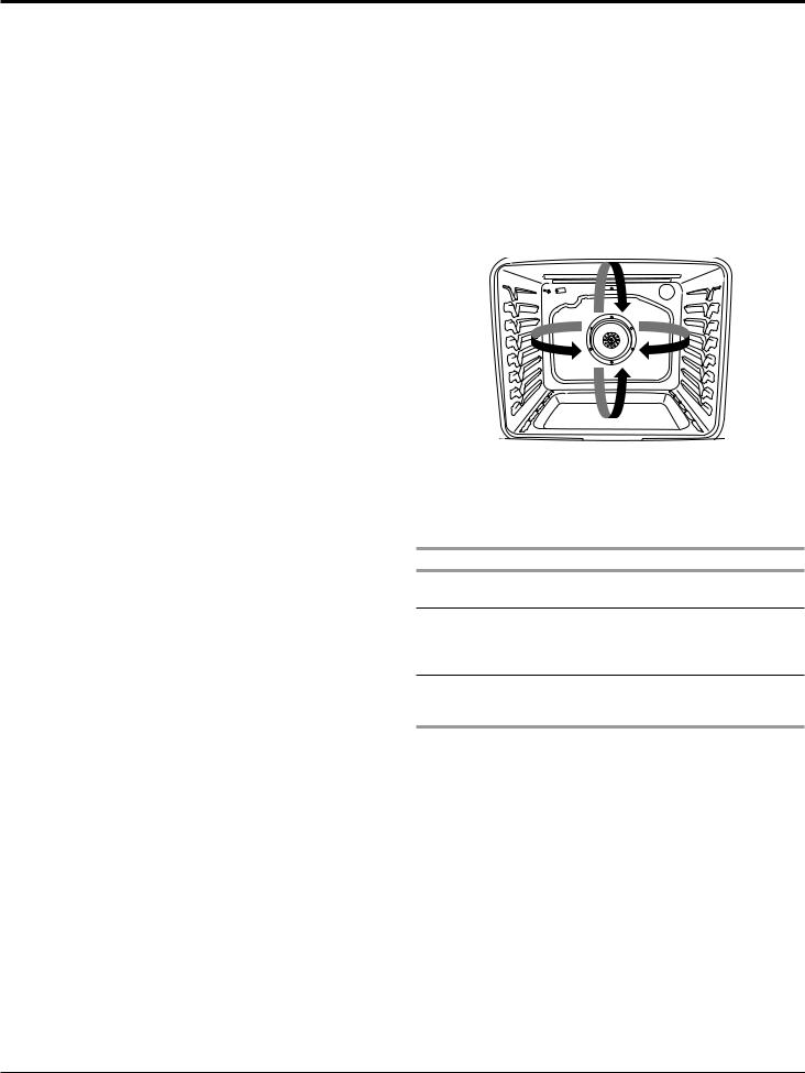
Preheating and Oven Temperature
Preheating
When beginning a Bake, Convect Bake, or Convect Roast cycle, the oven will begin preheating after Start is pressed. The oven will take approximately 12 to 17 minutes to reach 350°F (177°C) with all of the oven racks provided with your oven inside the oven cavity. Higher temperatures will take longer to preheat. The preheat cycle rapidly increases the oven temperature. The actual oven temperature will go above your set temperature to offset the heat lost when your oven door is opened to insert food. This ensures that when you place your food in the oven, the oven, will begin at the proper temperature. Insert your food when
the preheat tone sounds. Do not open the door during preheat before the tone sounds.
Rapid Preheat
Rapid Preheat can be used to shorten the preheating time. Only one standard flat oven rack should be in the oven during Rapid Preheat. Extra racks should be removed prior to starting. The preheating cycle should be completed before placing food in the oven. When the Rapid Preheat cycle is complete, the oven starts a normal Bake cycle.
IMPORTANT: Rapid Preheat should be used only for one-rack baking.
Oven Temperature
While in use, the oven elements will cycle on and off as needed to maintain a consistent temperature, but they may run slightly hot or cool at any point in time due to this cycling. Opening the oven door while in use will release the hot air and cool the oven which could impact the cooking time and performance. It is recommended to use the oven light to monitor cooking progress.
NOTE: On models with convection, the convection fan may run in the non-convection bake mode to improve oven performance.
Whirlpool® Smart Wall Ovens n 1-9
GENERAL INFORMATION
Baking and Roasting
IMPORTANT: The convection fan and convection element may operate during the Bake function to enhance performance and heat distribution.
The oven will take approximately 12 to 17 minutes to reach 350°F (177°C) with all oven racks inside the oven cavity. The preheat cycle rapidly increases the temperature inside the oven cavity. Higher temperatures will take longer to preheat. Factors that impact preheat times include room temperature, oven temperature, and the number of racks. Unused oven racks can be removed prior to preheating your oven to help reduce preheat time. The actual oven temperature will go above the set temperature to offset the heat lost when the oven door is opened to insert food. This ensures that the oven will begin at the proper temperature when you place food in the oven. Insert food when the preheat tone sounds. Do not open the door during preheat until the tone sounds.
During baking or roasting, the bake and broil elements will cycle on and off in intervals to maintain the oven temperature.
Depending on the model, if the oven door is opened during baking or roasting, the heating elements (bake and broil) will turn off approximately 30 seconds after the door is opened. They will turn on again approximately 30 seconds after the door is closed.
Frozen Bake™
Frozen Bake™ Technology automatically adjusts the manufacturer’s bake time by combining preheating and baking to deliver great packaged frozen food results without the wait. There are multiple preprogrammed food options. The Frozen Bake™ cycle have been customized to work only with these foods. When using Frozen Bake™ Technology, it is important that you follow all manufacturer’s instructions including venting, covering, stirring or placing on a baking sheet to ensure a good result. When cooking frozen meals, only cook items that provide instructions for cooking in a conventional oven. Place your dish in the center of the rack and select one of the rack positions recommended for Frozen Bake™ in the “Positioning Racks and Bakeware” section and bake only one package or pan at a time. Use the temperature and maximum bake time from the package.
A tone will alert you to check the food for doneness before the cook time is complete and again at the end of the cook time. The display will prompt you to add additional cook time if needed.
Broiling
When broiling, no preheating is necessary unless recommended otherwise in the recipe. Position food on grid in a broiler pan, and then place it in the center of the oven rack. Close the oven door to ensure proper broiling temperature.
NOTE: Odors and smoke are normal the first few times the oven is used or if the oven is heavily soiled.
Changing the temperature when broiling allows more precise control when cooking. The lower the broil setting, the slower the cooking. Thicker cuts and unevenly shaped pieces of meat, fish and poultry may cook better at lower broil settings. Place the food in the lower oven. Refer to the “Positioning Racks and Bakeware” section for more information.
On lower settings, the broil element will cycle on and off to maintain the proper temperature.
For best results, use a broiler pan and grid. It is designed to drain juices and help avoid spatter and smoke.
If you would like to purchase a broiler pan, one may be ordered. Please refer to the “Accessories” section for more information.
Convection Cooking
In a convection oven, the fan-circulated hot air continually distributes heat more evenly than the natural movement of air in a standard thermal oven. This movement of hot air helps
maintain a consistent temperature throughout the oven, cooking foods more evenly, crisping surfaces while sealing in moisture and yielding crustier breads.
During convection cooking, the bake, broil and convection (true convection only) elements cycle on and off in intervals to maintain the oven temperature, while the fan circulates the hot air.
If the oven door is opened during convection cooking, the fan will turn off immediately. It will come back on when the oven door is closed.
NOTE: The oven door must be closed for convection broiling.
Position the racks according to the “Positioning Racks and Bakeware” section before starting convection cooking.
With convection cooking, most foods can be cooked at a lower temperature for a shorter length of time. These adjustments can be made using the following chart.
Setting Guidelines
Convect Bake Reduce the standard baking temperature 25°F (15°C).
Convect Roast Use standard recipe temperature. Cooking time may be reduced by 15% to 30%
with Convect Roast so the food should be checked for doneness early.
Convect Broil Use standard recipe temperature. Cooking time may be reduced so the food should be checked for doneness early.
Convert Time/Temp
Convection temperatures and times differ from those of standard cooking. The Convert Time/Temp convection feature is a function that converts a standard thermal bake or roast cook time and temperature into an ideal cook time and temperature for convection cooking. The displayed time and temperature will be the converted for convection values.
1-10 n Whirlpool® Smart Wall Ovens

GENERAL INFORMATION
Temperature Probe
The temperature probe accurately measures the internal temperature of meat, poultry and casseroles with liquid and should be used in determining the doneness of meat and poultry.
The temperature probe should only be used with Bake, Convect Bake, or Convect Roast.
Always unplug and remove the temperature probe from the oven when removing food.
To Use:
Before using, insert the probe into the food item. For meats, the probe tip should be located in the center of the thickest part of the meat and not into the fat or touching a bone. Place food in oven and connect the temperature probe to the jack. Keep probe as far away from heat source as possible. Close oven door.
NOTE: The temperature probe must be inserted into the food item before the mode is selected.
Use the Assisted Cooking feature for guidance and step by step instructions on inserting the probe and selecting target food internal temperatures
Plug the probe into the oven’s port or pick the Probe icon in the Tools Menu. Both will show a pop-up that allows user to pick the cooking mode and all of the options. Place food in the oven and connect the temperature probe to the jack.
Keep the probe as far away from the heat source as possible.
Close the oven door.
Model & Serial Number Location
Model & Serial Number Label
Location For Combo Unit
Model & Serial Number Label
Location For Single/Wall Oven
Whirlpool® Smart Wall Ovens n 1-11

GENERAL INFORMATION
Model & Serial Number Nomenclature
MODEL NUMBER |
W O |
C |
5 4 E C O H |
INTERNATIONAL SALES OR
MARKETING CHANNEL
BRAND
W = Whirlpool
PLATFORM
O = WALL OVEN
SUB PLATFORM
S = SINGLE OVEN
D = DOUBLE OVEN
C = COMBO MICROWAVE OVEN
SERIES
5 = MID LINE
7 = HIGH (GOLD)
9 = HERO (GOLD)
FEATURE LEVEL
1 = THERMAL Wall Oven(s)
2 = TRUE CONVECTION Wall Oven(s)
3 = UPPER TRUE CONVECTION/LOWER THERMAL
4 = MICRO WAVE UPPER/LOWER THERMAL
5 = MICRO WAVE UPPER/LOWER TRUE CONVECTION
KEY FEATURE
E = ELECTRIC
G = GAS
I = INDUCTION
M = STANDARD CLEAN
W = STEAM CLEAN
S = SELF CLEAN
H = HE SELF CLEAN
C = STEAM CLEAN & SELF CLEAN
0 = 30" WIDTH
7 = 27" WIDTH
YEAR PF MARKET INTRODUCTION
G = 2017
H = 2018
J = 2019
SERIAL NUMBER |
D |
7 |
47 |
03117 |
DIVISION RESPONSIBILITY
D = Cleveland
YEAR OF PRODUCTION 5 = 2015 6 = 2016 7 = 2017
WEEK OF PRODUCTION 47 = 47th week
PRODUCT SEQUENCE NUMBER
1-12 Whirlpool® Smart Wall Ovens

|
|
|
|
GENERAL INFORMATION |
|
|
|
Tech Sheet Location |
|||
|
Tech Sheet Location |
|
|
Tech Sheet Location |
|
|
For Combo Unit |
|
|
For Single and Double Wall Oven |
|
|
(side of oven shroud) |
|
|
(top panel) |
|
|
|
|
|
||
|
|
|
|
|
|
|
|
|
|
|
|
|
|
|
|
|
|
Whirlpool® Smart Wall Ovens n 1-13

GENERAL INFORMATION
1-14 n Whirlpool® Smart Wall Ovens

Back to Table of Contents |
DIAGNOSTICS & TROUBLESHOOTING |
|
|
Section 2: |
|
|
Diagnostics |
|
■ Safety
■ 
■ 
Whirlpool® Smart Wall Ovens 2-1
DIAGNOSTICS & TROUBLESHOOTING
For Service Technician Use Only
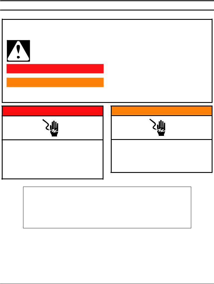
Safety
Your safety and the safety of others are very important.
many important safety messages in this manual and on your appliance. Always read and obey all safety
safety alert symbol.
alerts you to potential hazards that can kill or hurt you and others.
messages will follow the safety alert symbol and either the word “DANGER” or “WARNING.” mean:
 DANGER
  WARNING
You can be killed or seriously injured if you don't immediately follow instructions.
You can be killed or seriously injured if you don't follow instructions.
All safety messages will tell you what the potential hazard is, tell you how to reduce the chance of injury, and tell you what can happen if the instructions are not followed.
 DANGER
Electrical Shock Hazard
Only authorized technicians should perform diagnostic voltage measurements.
After performing voltage measurements, disconnect power before servicing.
Failure to follow these instructions can result in death or electrical shock.
 WARNING
Electrical Shock Hazard Disconnect power before servicing.
Replace all parts and panels before operating.
Failure to do so can result in death or electrical shock.
Voltage Measurement Safety Information
When performing live voltage measurements, you must do the following:
■Verify the controls are in the off position so that the appliance does not start when energized.
■Allow enough space to perform the voltage measurements without obstructions.
■Keep other people a safe distance away from the appliance to prevent potential injury.
■Always use the proper testing equipment.
■After voltage measurements, always disconnect power before servicing.
2-2 n Whirlpool® Smart Wall Ovens
DIAGNOSTICS & TROUBLESHOOTING
For Service Technician Use Only
IMPORTANT: Electrostatic Discharge (ESD) Sensitive Electronics
ESD problems are present everywhere. ESD may damage or weaken the electronic control assembly. The new control assembly may appear to work well after repair is finished, but failure may occur at a later date due to ESD stress.
■Use an antistatic wrist strap. Connect wrist strap to green ground connection point or unpainted metal in the appliance
-OR-
Touch your finger repeatedly to a green ground connection point or unpainted metal in the appliance.
■Before removing the part from its package, touch the antistatic bag to a green ground connection point or unpainted metal in the appliance.
■Avoid touching electronic parts or terminal contacts; handle electronic control assembly by edges only.
■When repackaging failed electronic control assembly in antistatic bag, observe above instructions.
Diagnostics Mode
IMPORTANT: Before powering MWO magnetron, be sure that a load, such as a microwave-safe cup of water, is present in the microwave oven cavity.
Unplug microwave oven or disconnect power before performing the following checks:
A potential cause of a control not functioning is corrosion on connections. Observe connections and check for continuity with an ohmmeter.
All tests/checks should be made with a VOM or DVM having a sensitivity of 20,000 Ω per Volt DC or greater.
Check all connections before replacing components, looking for broken or loose wires, failed terminals, or wires not pressed into connectors far enough. The damaged harness must be entirely replaced. Do not rework a harness.
Resistance checks must be made with power cord unplugged from outlet, and with wiring harness or connectors disconnected.
IMPORTANT: Do not replace the control if there is no evidence of any failure.
There are two ways to enter Diagnostics mode.
Option A
Before proceeding with any corrective action, perform the following steps to enter the Diagnostics mode:
1.Enter Diagnostics mode by pressing the same 3 keypads 3 times in a row.
Single Ovens: Press HOME > FAVORITES > LIGHT (Repeat two more times.)
Double Ovens: Press HOME > FAVORITES > LIGHT (Repeat two more times.)
2.The warning will be displayed. Press ENTER.
NOTE: You do not need to wait for any audible or visual feedback from the control between keypad presses.
3.If the control does not enter Diagnostics mode, continue repeating the keypad sequence from Step 1.
4.From the Diagnostic Menu, scroll to the desired selection using the touchscreen.
Option B
Before proceeding with any corrective action, perform the following steps to enter the Diagnostics mode:
1.Press Tools > Info > Service and Support. Press diagnostics button for 1 minute. Press 1, 2, 3, 1, 2, 3, 1, 2, 3. Press ENTER.
NOTE: The warning will be displayed. Press ENTER.
2.If the control does not enter Diagnostics, continue repeating the keypad sequence from Step 1. All the keypads will light up when the control enters Diagnostics.
3.From the Diagnostic Menu, scroll to the desired selection using the touchscreen.
Error Diagnostics: View and clear the failure history.
Component Activation: Manually activate each relay.
Sensors & Switches: View the traditional oven cavity temperatures and door/latch switch status.
System Information: View the model number, serial number, and software versions.
Wi-Fi: View Wi-Fi related content such as IP Address,
Gateway, SSID, and connection status.
General Procedure: Error Codes
NOTE: All failures are stored in the failure history. To check if the error code is still present, start a cooking function and wait
1 minute to check if the error appears.
1.Enter Error Diagnostics.
2.Touch “Error Diagnostics” in the Diagnostics menu, and then touch OK.
Error Diagnostic
F4E1
Fri Jan 2 15:27:48
F2E5
Wed Dec 31 20:58:42
3.To clear error codes, touch “Clear History”.
4.If no failures are listed, the message “No Error” will appear on the screen.
General Procedure: Component Activation
1.Enter Component Activation.
2.Touch “Component Activation”.
NOTE: The loads are switched off, if they remain active for more than 5 minutes.
Whirlpool® Smart Wall Ovens n 2-3

DIAGNOSTICS & TROUBLESHOOTING
For Service Technician Use Only
Single Oven Model
Selection |
Relay |
|
|
Bake Element |
Bake Relay |
|
|
Broil Element |
Broil Relay |
|
|
Convection Element |
Convection Relay |
|
|
Convection Fan |
Convection Fan Relay |
|
|
Cooling Fan High Speed |
Cooling Fan High Relay |
|
|
Cooling Fan Low Speed |
Cooling Fan Low Triac |
|
|
Oven Light |
Oven Light Triac |
|
|
Door Latch Motor |
Door Latch Relay |
Double Oven Model |
|
Selection |
Relay |
|
|
Upper Bake Element |
Upper Bake Element Relay |
|
|
Upper Broil Element |
Upper Broil Element Relay |
|
|
Upper Convection Element |
Upper Cavity Convection |
|
Element Relay |
Upper Convection Fan |
Upper Cavity Convection Fan |
|
Relay |
Upper Cooling Fan High |
Upper Cooling Fan High Speed |
Speed |
Relay |
Upper Cooling Fan Low |
Upper Cooling Fan Low Speed |
Speed |
Triac |
Upper Oven Light |
Upper Oven Light Triac |
|
|
Upper Door Latch Motor |
Upper Door Latch Motor Relay |
|
|
Lower Bake Element |
Lower Bake Element Relay |
|
|
Lower Broil Element |
Lower Broil Element Relay |
|
|
Lower Convection Element |
Lower Cavity Convection |
|
Element Relay |
|
|
Lower Convection Fan |
Lower Cavity Convection Fan |
|
Relay |
|
|
Lower Cooling Fan High |
Lower Cooling Fan High Speed |
Speed |
Relay |
|
|
Lower Cooling Fan Low |
Lower Cooling Fan Low Speed |
Speed |
Triac |
|
|
Lower Oven Light |
Lower Oven Light Triac |
|
|
Lower Door Latch Motor |
Lower Door Latch Motor Relay |
|
|
Microwave Oven Combination - Lower
Oven
Selection |
Relay |
MW Light |
MW Light Relay |
|
|
MW Turntable |
MW Turntable Relay |
|
|
MW Cooling Fan |
MW Cooling Fan Relay |
|
|
MW Magnetron/Cooling Fan |
MW Magnetron and MW |
|
Cooling Fan Relay |
Oven Bake Element |
Oven Bake Element Relay |
|
|
Oven Broil Element |
Oven Broil Element Relay |
|
|
Convection Element |
Convection Element Relay |
|
|
Convection Fan |
Convection Fan Relay |
|
|
Oven Cooling Fan High |
Oven Cooling Fan High Speed |
Speed |
Relay |
|
|
Oven Cooling Fan Low Speed |
Oven Cooling Fan Low Speed |
|
Relay |
|
|
Oven Light |
Oven Light Triac |
|
|
Oven Door Latch Motor |
Oven Door Latch Motor Relay |
General Procedure: System Information
NOTE: This procedure is to view the following system information:
1.Select TOOLS, then select INFO.
2.Select “Service and Support”.
3.Press and hold DIAGNOSTICS until Diagnostics screen shows.
4.Press 1, 2, 3, 1, 2, 3, 1, 2, 3, then press ENTER.
5.Touch “Diagnostics Home”.
6.Select “System Info”. See “Version Info” for below system information.
2-4 n Whirlpool® Smart Wall Ovens

DIAGNOSTICS & TROUBLESHOOTING
For Service Technician Use Only
Single & Double Oven Model
System |
Display |
Single |
Double |
Information |
|
Oven |
Oven |
Model # |
Model Information |
о |
о |
|
|
|
|
Serial # |
Product Serial Number |
о |
о |
|
|
|
|
UI Serial # |
User Interface Serial Number |
о |
о |
|
|
|
|
ACU Serial # |
Appliance Control Unit Serial |
о |
NA |
|
Number |
|
|
Upper ACU |
Upper Appliance Control Unit |
NA |
о |
Serial # |
Serial Number |
|
|
Lower ACU |
Lower Appliance Control Unit |
NA |
о |
Serial # |
Serial Number |
|
|
UI Version |
User Interface Software |
о |
о |
|
Version |
|
|
ACU SW |
Appliance Control Unit |
о |
NA |
|
Software Version |
|
|
Upper ACU |
Upper Appliance Control Unit |
NA |
о |
SW |
Software Version |
|
|
Lower ACU |
Lower Appliance Control Unit |
NA |
о |
SW |
Software Version |
|
|
Diagnostics |
Number of times Diagnostic |
о |
о |
Entries |
Menu has been entered |
|
|
Microwave Oven Combination - Lower
Oven
System Information |
Display |
|
|
Model # |
Model Information |
|
|
Serial # |
Product Serial Number |
|
|
UI Serial # |
User Interface Serial Number |
|
|
Oven ACU Serial # |
Appliance Control Unit Serial Number |
|
|
UI Version |
User Interface Software Version |
|
|
Oven ACU SW |
Oven Appliance Control Unit Software |
|
Version |
MWO ACU SW |
Microwave Oven Appliance Control Unit |
|
Software Version |
Diagnostics Entries |
Number of times Diagnostic Menu has |
|
been entered |
General Procedure: Model Selection
NOTE: When a new User Interface is installed, you will be prompted to select a new model number upon power up. To change the model number on an existing UI, follow the steps below:
1.Plug in microwave oven or connect power.
2.Enter Diagnostics mode.
3.Touch or scroll to “System Information” in the Diagnostics menu, then touch “OK”.
4.Touch or scroll to “Model Number,” then touch “OK”.
5.Touch or scroll to the correct model number in the list, then touch “Select”.
|
|
Failure/Error Display Codes |
||
Single Oven and Microwave Oven Combination |
||||
|
|
|
|
|
Code |
Description |
Explanation and Recommended Procedure |
|
|
User |
HMI-Central/UI |
NOTE: Before starting any test, cycle power to the oven (power off, wait 10 seconds, and power |
|
|
Interface |
board Control Panel |
on). |
|
|
(UI) not |
Assembly |
1. |
Enter the Diagnostic menu, and then touch POWER. |
|
reacting |
|
|
||
|
2. |
To reset Touch Calibration: Unplug the oven or disconnect power, wait 10 seconds, and then |
|
|
to touch |
|
|
||
|
|
|
plug in the oven or reconnect power. If still no response, go to Step 3. |
|
|
|
3. |
Unplug the oven or disconnect power. |
|
|
|
4. |
Replace HMI-Central/UI board Control Panel Assembly. |
|
|
|
5. |
Reassemble all parts and panels before operating. |
|
|
|
6. |
Plug in the oven or reconnect power and follow the on-screen prompts for a model |
|
|
|
|
selection. |
|
|
|
7. |
Verify operation is normal. |
|
|
|
|
|
|
Whirlpool® Smart Wall Ovens n 2-5

DIAGNOSTICS & TROUBLESHOOTING
For Service Technician Use Only
Code |
Description |
Explanation and Recommended Procedure |
|
|
|
||||
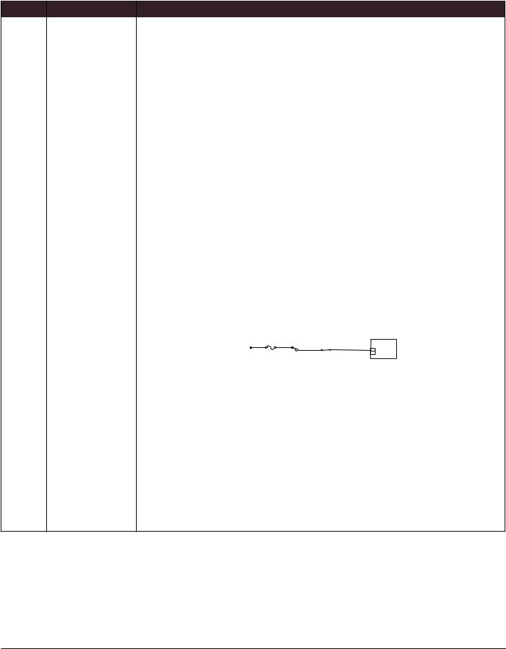
No Sound |
Speaker, HMI-Central/ |
NOTE: Before starting any test, cycle power to the oven (power off, wait 10 seconds, and power |
|||||||
|
UI board Control |
on). |
|
|
|
|
|
|
|
|
Panel Assembly |
1. |
Verify sound is enabled. Touch the Tools menu, and then scroll to the Sound menu. Confirm |
||||||
|
|
||||||||
|
|
|
Key Press, Timer & Alert, and Power On & Off actions are all turned on and set to the desired |
||||||
|
|
|
volume. |
|
|
|
|
|
|
|
|
2. |
Unplug the oven or disconnect power. |
|
|
|
|
|
|
|
|
3. |
Confirm the speaker is firmly connected to the UI board. If speaker is firmly connected, go to |
||||||
|
|
|
Step 4. If speaker connection is loose, reconnect and proceed to Step 5. |
||||||
|
|
|
Speaker BK |
|
|
|
|
|
|
|
|
|
2 |
J8 |
HMI-C |
|
|||
|
|
|
|
|
|||||
|
|
|
RD |
1 |
|
||||
|
|
|
|
User Interface |
|
||||
|
|
|
|
|
|
|
|||
|
|
4. |
|
|
|
|
|
||
|
|
Replace HMI-Central/UI board Control Panel Assembly. |
|||||||
|
|
5. |
Reassemble all parts and panels before operating. |
|
|
|
|||
|
|
6. |
Plug in the oven or reconnect power and follow the on-screen prompts for a model |
||||||
|
|
|
selection. |
|
|
|
|
|
|
|
|
7. |
Confirm operation of the speaker. If the problem persists, unplug the oven or disconnect |
||||||
|
|
|
power, replace HMI-Central/UI board Control Panel Assembly, and repeat steps 5 through 7. |
||||||
F1 |
Oven User Interface |
NOTE: Before starting any test, cycle power to the oven (power off, wait 10 seconds, then power |
|||||||
Internal |
(UI) Failure |
on). |
|
|
|
|
|
|
|
E0 |
|
PROCEDURE: Before proceeding, verify the error code by entering the Diagnostics Menu and |
|||||||
|
|
selecting “Error Diagnostics”. |
|
|
|
|
|
|
|
|
|
NOTE: If other error codes are stored, troubleshoot those other error codes first. |
|||||||
|
|
1. |
Unplug the oven or disconnect power. |
|
|
|
|
|
|
|
|
2. |
Confirm the HMI-Central/UI board Control Panel Assembly is grounded to the oven chassis. If |
||||||
|
|
|
it is, go to Step 6. If it is not, fix the connection. |
|
|
|
|||
|
|
3. |
Reassemble all parts and panels before operating. |
|
|
|
|||
|
|
4. |
Plug in the oven or reconnect power and cycle power. |
||||||
|
|
5. |
If error persists, unplug the oven or disconnect power. |
||||||
|
|
6. |
Replace HMI-Central/UI board Control Panel Assembly. |
||||||
|
|
7. |
Reassemble all parts and panels before operating. |
|
|
|
|||
|
|
8. |
Plug in the oven or reconnect power and follow the on-screen prompts for a model |
||||||
|
|
|
selection. |
|
|
|
|
|
|
|
|
9. |
Verify operation is normal. Enter Diagnostics mode, select “Error Diagnostics”, and clear the |
||||||
|
|
|
history. If the HMI-Central/UI board Control Panel Assembly was replaced, there is no need |
||||||
|
|
|
to clear the error history. |
|
|
|
|
|
|
2-6 n Whirlpool® Smart Wall Ovens
|
|
|
|
|
DIAGNOSTICS & TROUBLESHOOTING |
||||
|
|
For Service Technician Use Only |
|
||||||
|
|
|
|
|
|
|
|||
Code |
Description |
Explanation and Recommended Procedure |
|
|
|
|
|||
F1E1 |
Internal Oven ACU |
NOTE: Before starting any test, cycle power to the oven (power off, wait 10 seconds, then power |
|||||||
|
Error |
on). |
|
|
|
|
|
|
|
|
|
PROCEDURE: Before proceeding, verify the error code by entering the Diagnostics Menu and |
|||||||
|
|
selecting “Error Diagnostics”. |
|
|
|
|
|
|
|
|
|
NOTE: If other error codes are stored, troubleshoot those other error codes first. |
|||||||
|
|
1. |
Unplug the oven or disconnect power. |
|
|
|
|
|
|
|
|
2. |
Replace Copernicus ACU. |
|
|
|
|
|
|
|
|
3. |
Reassemble all parts and panels before operating. |
|
|
|
|
||
|
|
4. |
Plug in the oven or reconnect power. |
|
|
|
|
|
|
|
|
5. |
If error persists after Copernicus ACU is replaced, unplug the oven or disconnect power, and |
||||||
|
|
|
then go to Step 6. If not, go to Step 9. |
|
|
|
|
|
|
|
|
6. |
Replace HMI-Central/UI board Control Panel Assembly. |
|
|
|
|||
|
|
7. |
Reassemble all parts and panels before operating. |
|
|
|
|
||
|
|
8. |
Plug in the oven or reconnect power and follow the on-screen prompts for a model |
||||||
|
|
|
selection. |
|
|
|
|
|
|
|
|
9. |
Verify operation is normal. Enter Diagnostics mode, select “Error Diagnostics”, and clear the |
||||||
|
|
|
history. If the HMI-Central/UI board Control Panel Assembly was replaced, there is no need |
||||||
|
|
|
to clear the error history. |
|
|
|
|
|
|
F1E4 |
Microwave Oven |
NOTE: Before starting any test, cycle power to the oven (power off, wait 10 seconds, then power |
|||||||
|
Relay 4903 Error |
on). After powering on, be sure that a load, such as a microwave-safe cup of water, is present in |
|||||||
|
|
the microwave oven cavity, and start a microwave cooking function. Wait |
|||||||
|
|
1 minute, then verify that the failure happens again. |
|
|
|
|
|||
|
|
1. |
Make sure that all interlock switches work properly: When door is open, microwave light is |
||||||
|
|
|
on, when door is closed, microwave light is off. |
|
|
|
|
||
|
|
2. |
Unplug the oven or disconnect power. |
|
|
|
|
|
|
|
|
3. |
Check the following on the Microwave ACU: |
|
|
|
|
||
|
|
|
a. Wire connections to Relay 4903. |
|
|
|
|
|
|
|
|
|
Line Fuse |
|
Microwave Relay |
|
|
|
|
|
|
|
20A |
BR 1 |
|
Inverter |
|||
|
|
|
4903 |
BU |
|||||
|
|
|
L1 |
Primary |
|
CN702 |
|||
|
|
|
|
4 |
|
||||
|
|
|
|
Interlock |
|
|
|
|
|
|
|
|
|
Switch |
|
|
|
|
|
b. Check if Relay 4903 is shorted. If so, go to Step 7.
4.Reassemble all parts and panels before operating.
5.Plug in microwave oven or reconnect power.
6.To check if the error code is still present, be sure that a load, such as a microwave-safe cup of water, is present in the microwave oven cavity, and start a cooking function in the microwave oven. Wait 1 minute to check if the error appears. If error remains, go to Step 7. If not, go to
Step 10.
7.Unplug microwave oven or disconnect power and replace the Microwave ACU.
8.Reassemble all parts and panels before operating.
9.Plug in the oven or reconnect power and follow the on-screen prompts for a model selection.
10.Verify operation is normal. Enter Diagnostics mode, select “Error Diagnostics”, and clear the history. If the HMI-Central/UI board Control Panel Assembly was replaced, there is no need to clear the error history.
Whirlpool® Smart Wall Ovens n 2-7
DIAGNOSTICS & TROUBLESHOOTING
|
|
For Service Technician Use Only |
|
|
|
|
|
Code |
Description |
Explanation and Recommended Procedure |
|
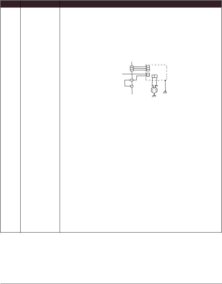
F1E5 |
Microwave Oven |
NOTE: Before starting any test, cycle power to the oven (power off, wait 10 seconds, then power |
|
|
Inverter Error |
on). After powering on, be sure that a load, such as a microwave-safe cup of water, is present in |
|
|
|
the microwave oven cavity, and start a microwave cooking function. Wait |
|
|
|
1 minute, then verify that the failure happens again. |
|
|
|
1. |
Make sure that all interlock switches works properly: when door is open, microwave light is |
|
|
|
on, and door is closed, microwave light is off. |
|
|
2. |
Unplug microwave oven or disconnect power. |
|
|
3. |
Check the following on the Microwave ACU: |
|
|
|
a. Relay 4903 |
|
|
|
b. Connector P8 |
|
P8 |
To MW |
321 |
|
|
Relay |
|
4903 |
P355 |
|
P354 |
|
CN701 |
|
|
3 |
|
BU |
12 |
MW Inverter |
|
PWM |
|
WH CN702 |
CN703 |
|
E701 |
||
|
RD |
RD |
|
|
YL/ |
Magnetron |
GN |
|
4. Check the following connections on the Inverter board: a. CN701
b. CN702 c. CN703
5.If the door works properly and all connections are okay, replace the Microwave Inverter Board.
6.Reassemble all parts and panels before operating.
7.Plug in microwave oven or reconnect power.
8.To check if the error code is still present, be sure that a load, such as a microwave-safe cup of water, is present in the microwave oven cavity,and start a cooking function in the microwave oven. Wait 1 minute to check if the error appears. If error remains, then go to Step 9. If not, go to Step 17.
9.Unplug the oven or disconnect power.
10.Replace the Magnetron.
11.Reassemble all parts and panels before operating.
12.Plug in microwave oven or reconnect power.
13.To check if the error code is still present, be sure that a load, such as a microwave-safe cup of water, is present in the microwave oven cavity,and start a cooking function in the microwave oven. Wait 1 minute to check if the error appears. If error remains, then go to Step 14. If not, go to Step 17.
14.Unplug microwave oven or disconnect power and replace the Microwave ACU.
15.Reassemble all parts and panels before operating.
16.Plug in the oven or reconnect power and follow the on-screen prompts for a model selection.
17.Verify operation is normal. Enter Diagnostics mode, select “Error Diagnostics”, and clear the history. If the HMI-Central/UI board Control Panel Assembly was replaced, there is no need to clear the error history.
2-8 n Whirlpool® Smart Wall Ovens
Loading...