


WET4027HW
Whirlpool WGTLV27HW, WGT4027HW, WETLV27HW, WET4124HW, WET4027HW User Manual
...
24" (61 cm) Electric & 27" (69 cm) Electric and
Gas Washer/Dryer Installation Instructions
Instructions pour l’installation de la laveuse/sécheuse
électrique de 24" (61 cm) et électrique et à gaz de 27" (69 cm)
Instrucciones de instalación de la lavadora/secadora
eléctrica de 24" (61 cm) y eléctrica y de gas de 27" (69 cm)
Table of Contents Table des matières
WASHER/DRYER SAFETY ..............................................................................2
INSTALLATION REQUIREMENTS ...................................................................5
LOCATION REQUIREMENTS ..........................................................................7
DIMENSIONS/CLEARANCES, 27" (69 CM) MODELS ...................................8
DIMENSIONS/CLEARANCES, 24" (61 CM) MODELS ..................................9
DRAIN SYSTEM .............................................................................................10
ELECTRICAL REQUIREMENTS, 240V ELECTRIC MODELS – U.S.A. ..........11
ELECTRICAL REQUIREMENTS, 120V ELECTRIC MODELS – U.S.A.
AND CANADA (24" [61 CM] MODELS ONLY) ..............................................12
ELECTRICAL REQUIREMENTS, 240V ELECTRIC MODELS – CANADA .....12
ELECTRICAL REQUIREMENTS, GAS MODELS
(27" [69 CM] MODELS ONLY) .......................................................................13
GAS SUPPLY REQUIREMENTS, GAS MODELS
(27" [69 CM] MODELS ONLY) .......................................................................13
REMOVE FOAM PACKING (24" [61 CM] MODELS) ....................................14
ELECTRICAL CONNECTION, 27" (69 CM) ELECTRIC MODELS
(U.S.A. ONLY) .................................................................................................15
ELECTRICAL CONNECTION, 24" (61 CM) 240V ELECTRIC MODELS
(U.S.A. ONLY) .................................................................................................21
VENTING ........................................................................................................25
CONNECT DRAIN HOSE ...............................................................................28
CONNECT INLET HOSES ..............................................................................29
MAKE GAS CONNECTION (GAS 27" [69 CM] MODELS ONLY) .................30
CONNECT VENT ............................................................................................31
FINAL INSTALLATION STEPS .......................................................................32
COMPLETE INSTALLATION CHECKLIST ....................................................35
SÉCURITÉ DE LA LAVEUSE/SÉCHEUSE ....................................................36
EXIGENCES D’INSTALLATION .....................................................................39
EXIGENCES D’EMPLACEMENT ..................................................................41
DIMENSIONS/DISTANCES DE DÉGAGEMENT,
MODÈLES DE 27" (69 CM) ............................................................................42
DIMENSIONS/DISTANCES DE DÉGAGEMENT,
MODÈLES DE 24" (61 CM) ............................................................................43
SYSTÈME DE VIDANGE ................................................................................44
SPÉCIFICATIONS ÉLECTRIQUES, MODÈLES ÉLECTRIQUES
DE 120V (MODÈLES DE 24" [61 CM] UNIQUEMENT – CANADA ...............45
SPÉCIFICATIONS ÉLECTRIQUES, MODÈLES ÉLECTRIQUES
DE 240V – CANADA .......................................................................................45
SPÉCIFICATIONS ÉLECTRIQUES, MODÈLES À GAZ
(MODÈLES DE 27" [69 CM] UNIQUEMENT) ................................................46
SPÉCIFICATIONS DE L’ALIMENTATION EN GAZ, MODÈLES À GAZ
(MODÈLES DE 27" [69 CM] UNIQUEMENT) ................................................47
ENLEVER L’EMBALLAGE EN MOUSSE (MODÈLES DE 24" [61 CM]) .......48
ÉVACUATION .................................................................................................49
RACCORDEMENT DU TUYAU DE VIDANGE ...............................................52
RACCORDEMENT DES TUYAUX D’ARRIVÉE D’EAU .................................53
RACCORDEMENT À LA CANALISATION DE GAZ
(MODÈLES À GAZ DE 27" [69 CM] UNIQUEMENT) ....................................54
RACCORDEMENT DU CONDUIT D’ÉVACUATION .....................................55
ÉTAPES D’INSTALLATION FINALES ............................................................56
LISTE DE VÉRIFICATION POUR L’ACHÈVEMENT
DE L’INSTALLATION ......................................................................................59
Índice
SEGURIDAD DE LA LAVADORA/SECADORA .............................................60
REQUISITOS DE INSTALACIÓN ...................................................................63
REQUISITOS DE UBICACIÓN .......................................................................65
DIMENSIONES Y ESPACIOS LIBRES, MODELOS DE 27" (69 CM) ...........66
DIMENSIONES Y ESPACIOS LIBRES, MODELOS DE 24" (61 CM) ...........67
SISTEMA DE DESAGÜE ................................................................................68
REQUISITOS ELÉCTRICOS, MODELOS ELÉCTRICOS DE 240V ...............69
REQUISITOS ELÉCTRICOS, MODELOS ELÉCTRICOS DE 120V
(MODELOS DE 24" [61 CM] SOLAMENTE) ..................................................70
REQUISITOS ELÉCTRICOS, MODELOS A GAS
(MODELOS DE 27" [69 CM] SOLAMENTE) ..................................................71
REQUISITOS DEL SUMINISTRO DE GAS, MODELOS A GAS
(MODELOS DE 27" [69 CM] SOLAMENTE) ..................................................72
INSTALLATION NOTES
Date of purchase: ________________________________________
Date of installation: _______________________________________
Installer: _________________________________________________
Model number: ___________________________________________
Serial number: ___________________________________________
NOTAS DE INSTALACIÓN
Fecha de la compra: ______________________________________
Fecha de la instalación: ___________________________________
Instalador: _______________________________________________
Número de modelo: ______________________________________
Número de serie: _________________________________________
QUITE EL EMBALAJE DE HULE ESPUMA (MODELOS DE 24" [61 CM]) ....73
CONEXIÓN ELÉCTRICA, MODELOS ELÉCTRICOS
DE 27" (69 CM) (EE.UU. SOLAMENTE) ........................................................74
CONEXIÓN ELÉCTRICA, MODELOS ELÉCTRICOS
DE 24" (61 CM) DE 240V (EE.UU. SOLAMENTE) .........................................80
VENTILACIÓN ................................................................................................84
CONECTE LA MANGUERA DE DESAGÜE ...................................................87
CONECTE LAS MANGUERAS DE ENTRADA ..............................................88
CONEXIÓN DEL SUMINISTRO DE GAS (MODELOS A GAS
DE 27" [69 CM] SOLAMENTE) ......................................................................89
CONECTE EL DUCTO DE ESCAPE ..............................................................90
PASOS FINALES DE INSTALACIÓN .............................................................91
LISTA DE CONTROL PARA LA REALIZACIÓN
DE LA INSTALACIÓN .....................................................................................94
NOTES CONCERNANT L’INSTALLATION
Date d’achat : ____________________________________________
Date d’installation : _______________________________________
Installateur : _____________________________________________
Numéro de modèle : ______________________________________
Numéro de série : ________________________________________
W11028718A
Washer/Dryer Safety
2
WARNING:
FIRE OR EXPLOSION HAZARD
Failure to follow safety warnings exactly could result in serious injury, death, or property
damage.
–
Do not store or use gasoline or other ammable vapors and liquids in the vicinity of this
or any other appliance.
–
WHAT TO DO IF YOU SMELL GAS:
Do not try to light any appliance.
•
Do not touch any electrical switch; do not use any phone in your building.
•
Clear the room, building, or area of all occupants.
•
Immediately call your gas supplier from a neighbor’s phone. Follow the gas supplier’s
•
instructions.
If you cannot reach your gas supplier, call the re department.
•
–
Installation and service must be performed by a qualied installer, service agency, or
the gas supplier.
In the State of Massachusetts, the following installation instructions apply:
■ Installations and repairs must be performed by a qualified or licensed contractor, plumber, or gas fitter qualified or licensed by
the State of Massachusetts.
■ Acceptable Shut-off Devices: Gas Cocks and Ball Valves installed for use shall be listed.
■ A flexible gas connector, when used, must not exceed 4 feet (121.9 cm).
IMPORTANT: The gas installation must conform with local codes, or in the absence of local codes, with the National Fuel Gas
Code, ANSI Z223.1/NFPA 54, or the Natural Gas and Propane Installation Code, CSA B149.1.
The dryer must be electrically grounded in accordance with local codes, or in the absence of local codes, with the National
Electrical Code, ANSI/NFPA 70, or the Canadian Electrical Code, Part 1, CSA C22.1.
3
4
Installation Requirements
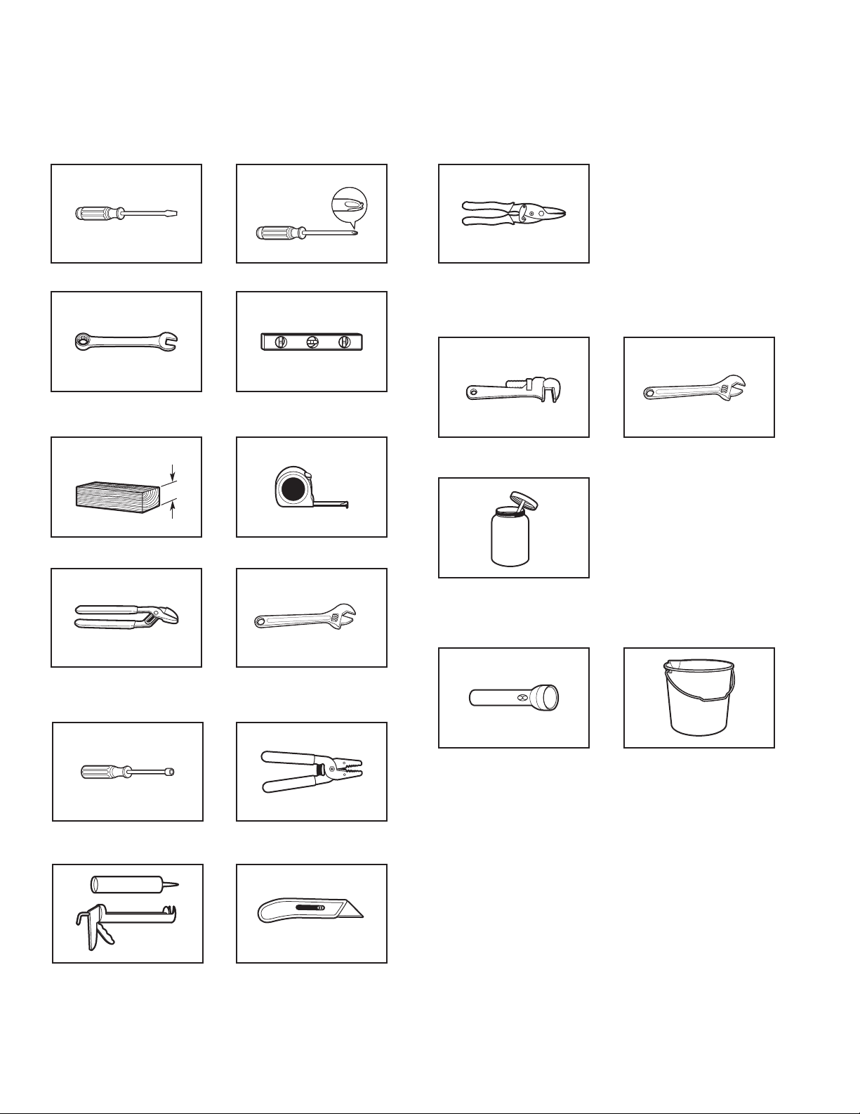
Tools and Parts
Gather required tools and parts before starting installation.
Tools needed:
Flat-blade screwdriver #2 Phillips screwdriver
Adjustable or open-end
wrench 9/16" (14 mm)
4" min
(102 mm)
Wood block
Pliers that open to 19/16"
(39.5 mm)
Level
Ruler or measuring tape
Adjustable wrench that
opens to 1" (25 mm) or
hex-head socket wrench
Tin snips (new vent
installations)
Tools needed for gas installations:
8" (203 mm) or 10"
(254 mm) pipe wrench
Pipe-joint compound
resistant to propane gas
8" (203 mm) or 10"
(254 mm) adjustable wrench
(for gas connections)
Optional tools:
1/4" (6.5 mm) nut driver
(recommended)
Caulking gun and compound
(new vent installations)
Flashlight Bucket
Wire stripper
Utility knife
5
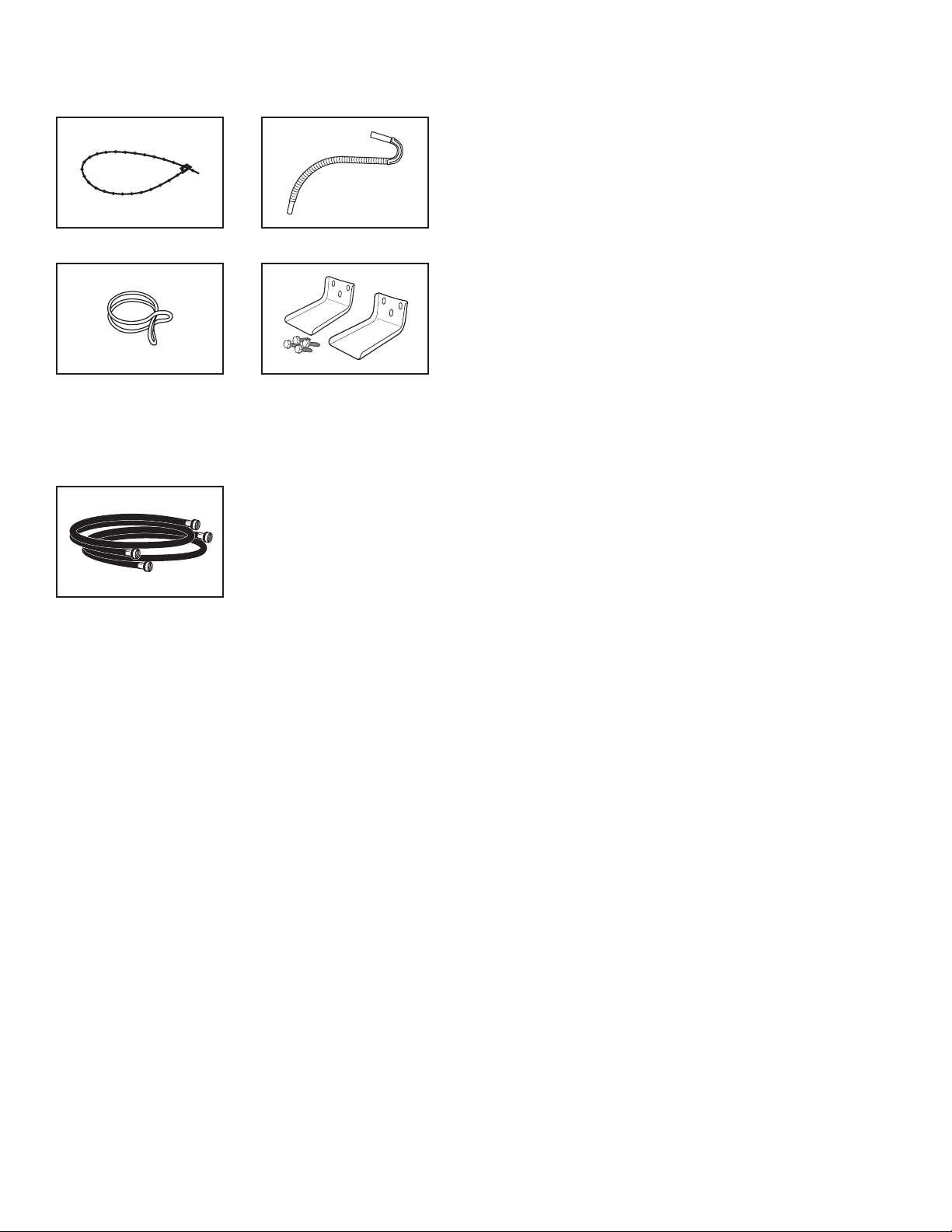
Parts supplied:
NOTE: Remove parts package from the washer basket.
Check that all parts were included.
Plastic strap
Silver double-wire
hose clamp
Drain hose
Anti-tip brackets (2)
and screws (4)
(27" [69 cm] models)
Parts needed: (Not supplied with washer/dryer)
n
Vent clamps
n
Vent elbows and ductwork
n
Mobile Home Installation Kit
(Part Number 346764)
n
Metal exhaust system hardware
Alternate parts: (Not supplied with washer/dryer)
Your installation may require additional parts. To order, please
refer to the toll-free numbers on the back page of your Use and
Care Guide.
If you have: You will need:
Overhead sewer Standard 20 gal. (76 L) 39" (991 mm)
tall Drain Tub or Utility Sink, Sump
Pump and Connectors (available from
local plumbing suppliers)
Floor drain Siphon Break Part Number 285320,
Additional Drain Hose Part Number
285702, and Connector Kit Part
Number 285442
1" (25 mm) standpipe 2" (51 mm) diameter to 1" (25 mm)
diameter Standpipe Adapter
Part Number 3363920,
Connector Kit Part Number 285835
Laundry tub or Sump pump system (if not already
standpipe taller than available)
96" (2.4 m)
Drain hose too short Extension Drain Hose
Part Number 285863,
Connector Kit Part Number 285835
Lint clogged drain Drain Protector Part Number 367031,
Connector Kit Part Number 285835
Water faucets Two longer water ll hoses:
beyond reach 6 ft (1.8 m) Part Number 76314,
of ll hoses 10 ft (3.0 m) Part Number 350008
Inlet hoses with
flat washers
Check local codes, electrical supply and venting, and read
“Electrical Requirements” and “Venting Requirements” before
purchasing parts. Mobile home installations require metal
exhaust system hardware available for purchase from the
dealer from whom you purchased your washer/dryer. For
further information, please reference the “Assistance or
Service” section of the Washer/Dryer Use and Care Guide.
Optional equipment: (Not supplied with washer/dryer)
Refer to your Use and Care Guide for information about
accessories available for your washer/dryer.
6
Location Requirements
(155 cm
Recessed area or closet installation
2
48 in.
(310 cm2)
3"
(76 mm)
Select proper location for your washer/dryer to improve
performance and minimize noise and possible “washer walk.”
Install your washer/dryer in a basement, laundry room, closet,
or recessed area.
You will need:
nA location that allows for proper exhaust installation.
A washer/dryer must be exhausted to the outdoors.
See “Venting Requirements.”
n For 27" (69 cm) and 24" (61 cm) 240V electric models, a
separate 30 amp circuit. For 24" (61 cm) 120V electric models,
a separate 20 amp circuit. For gas models, a separate 120V
15 or 20 amp circuit.
nFor 27" (69 cm) electric models using a power supply
cord, for 24" (61 cm) electric models, and for gas models,
a grounded electrical outlet located within 2 ft (610 mm) of
either side of the washer/ dryer. See “Electrical Requirements.”
nA sturdy oor to support the washer/dryer weight (washer/
dryer, water, and load) of 500 lbs (226.8 kg).
nA level oor with a maximum slope of 1" (25 mm) under entire
washer/dryer. Clothes may not tumble properly and automatic
sensor cycles may not operate correctly if washer/dryer is not
level. Installing on carpet is not recommended.
n A water heater set to deliver 120°F (49°C) water to the washer.
nHot and cold water faucets located within 4 ft (1.2 m) of the
hot and cold water ll valves, and water pressure of 5–100 psi
(34.5–689.6 kPa).
The washer/dryer must not be installed or stored in an area where
it will be exposed to water and/or weather.
Do not operate your washer in temperatures at or below 32ºF
(0ºC). Some water can remain in the washer and can cause
damage in low temperatures. See “Washer/Dryer Care” in the
Washer/Dryer Use and Care Guide for winterizing information.
Do not operate your dryer at temperatures below 45°F (7°C).
At lower temperatures, the dryer might not shut off at the end
of an automatic cycle. This can result in longer drying times.
Check code requirements. Some codes limit, or do not permit,
installation of the washer/dryer in garages, closets, mobile
homes, or sleeping quarters. Contact your local building
inspector.
Front
View
24 in.
2
2
)
Closet
door
3"
(76 mm)
The spacing dimensions on the following pages are
recommended for this washer/dryer. This washer/dryer
has been tested for spacing of 0" (0 mm) clearance at
the sides and back. Recommended spacing should be
considered for the following reasons:
nAdditional spacing should be considered for ease of
installation and servicing.
nAdditional clearances might be required for wall, door,
and oor moldings.
nAdditional spacing on all sides of the washer/dryer is
recommended to reduce noise transfer.
nFor closet installation, with a door, minimum ventilation
openings in the top and bottom of the door are required.
Louvered doors with equivalent ventilation openings are
acceptable.
NOTE: For gas models, no other fuel-burning appliance can
be installed in the same closet as the washer/dryer.
Mobile Home – Additional Installation Requirements
This washer/dryer is suitable for mobile home installations.
The installation must conform to the Manufactured Home
Construction and Safety Standard, Title 24 CFR, Part 3280
(formerly the Federal Standard for Mobile Home Construction
and Safety, Title 24, HUD Part 280) or the Canadian
Manufactured Home Standard, CAN/CSA-Z240 MH.
Mobile home installations require:
nMetal exhaust system hardware, which is available
for purchase from your dealer.
nMobile Home Installation Kit Part Number 346764 (gas
models only). See “Tools and Parts” for ordering information.
nSpecial provisions must be made in mobile homes to
introduce outside air into the dryer. The opening (such as a
nearby window) should be at least twice as large as the dryer
exhaust opening.
7
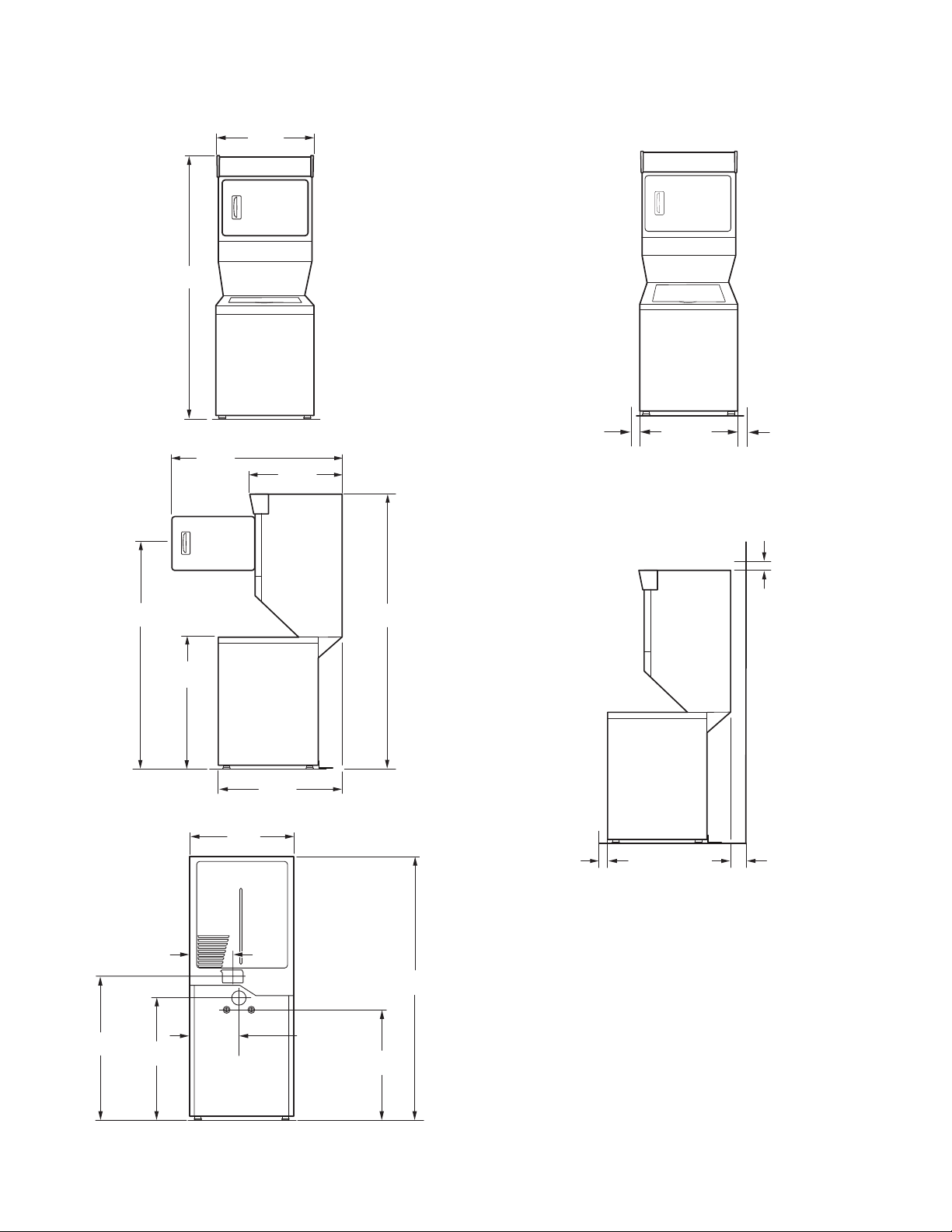
Dimensions/Clearances, 27" (69 cm) Models
(1918 mm)
(824 mm)
Dimensions
Front View
Side View
75½"
(1918 mm)
4715/16"
(1218 mm)
1
27
/4"
(692 mm)
(704 mm)
Clearances
Side Clearances (recommended/minimum)
1"/0"
(25 mm/0 mm)
11
27
/16"
Front/Back/Top Clearances (recommended/minimum)
1"/0"
(25 mm/0 mm)
Back View
6113/16"
(1570 mm)
11½"
(292 mm)
35¾"
(908 mm)
271/4"
(692 mm)
327/16"
75½"
75½"
(1918 mm)
1"
(25 mm)
(Closet)*
(25 mm/0 mm)
5"
(127 mm)**
1"/0"
13"
45"
(1143 mm)
39"
(991 mm)
(330 mm)
3615/16"
(938 mm)
**Required spacing.
** Rear clearance may be 0" (0 mm) when house exhaust system is lined up directly with dryer exhaust.
8
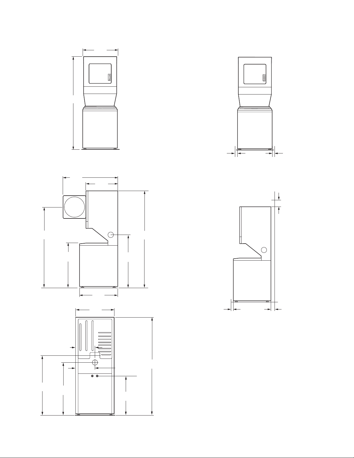
Dimensions/Clearances, 24" (61 cm) Models
)
(25 mm/0 mm
Dimensions
Front View
Side View
74¼"
(1886 mm)
7
/16"
36
(926 mm)
7
23
/8"
(607 mm)
20
¾
(527 mm)
Clearances
Side Clearances (recommended/minimum)
1"/0"
)
"
Front/Back/Top Clearances
1"/0"
(25 mm/0 mm
12"
(305 mm)
62"
(1575 mm)
Back View
5
47
(1210 mm)
/8"
3311/16"
(856 mm)
12"
(305 mm)
401/8"
(1019 mm)
265/8"
(676 mm)
237/8"
(607 mm)
40¼"
(1022 mm)
12"
(305 mm)
3115/16"
(811 mm)
74¼"
(1886 mm)
74¼"
(1886 mm)
1"
(25 mm)
(Closet)*
5"
(127 mm)**
**Required spacing.
** Rear clearance may be 0" (0 mm) when house exhaust system is lined up directly with dryer exhaust.
9
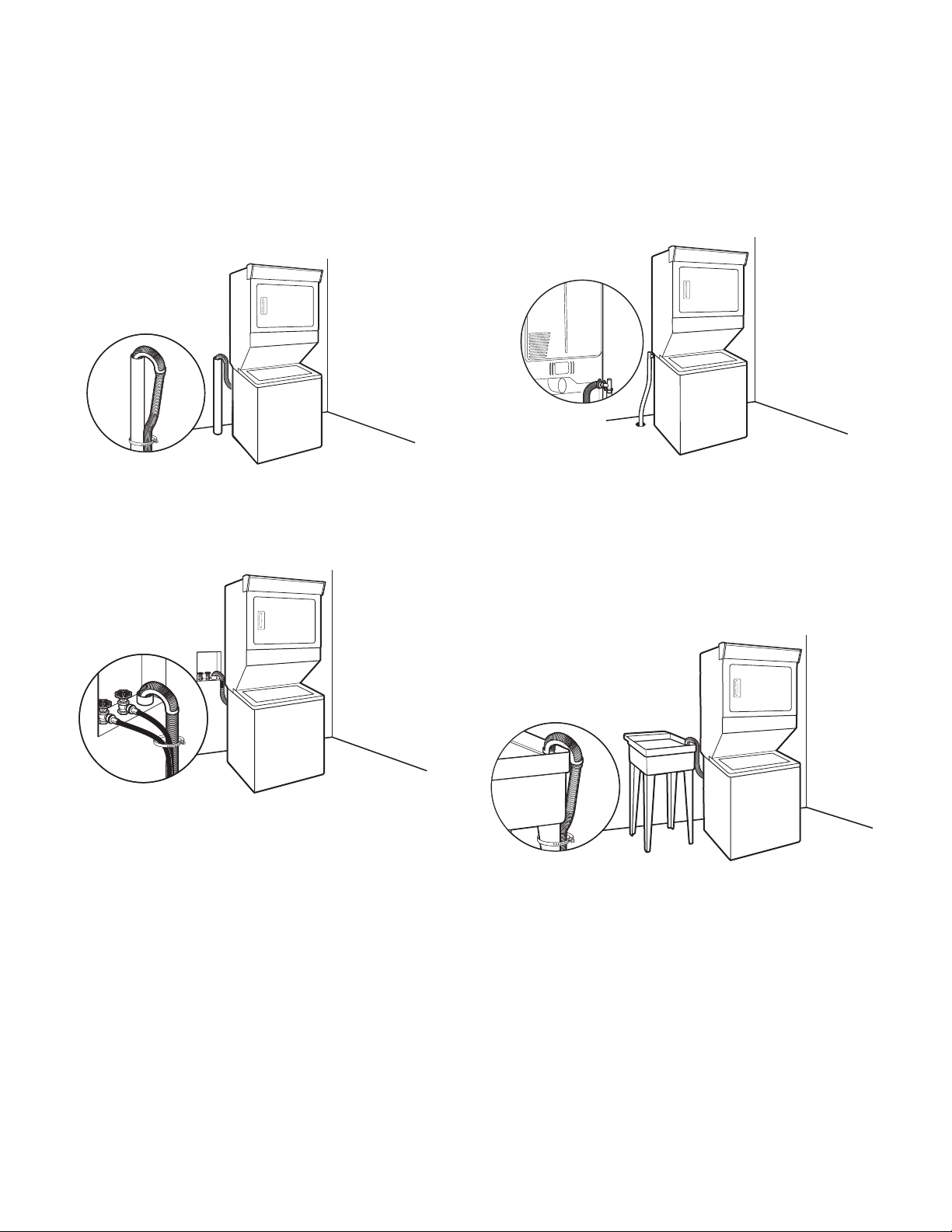
Drain System
Drain system can be installed using a oor drain, wall standpipe,
oor standpipe, or laundry tub. Select method you need.
Floor standpipe drain system
Minimum diameter for a standpipe drain: 2" (51 mm). Minimum
carry-away capacity: 17 gal. (64 L) per minute. Top of standpipe
must be at least 39" (991 mm) high; install no higher than 96"
(2.4 m) from bottom of washer/dryer. If you must install higher
than 96" (2.4 m), you will need a sump pump system.
Wall standpipe drain system
See requirements for oor standpipe drain system.
Floor drain system
Floor drain system requires a Siphon Break Kit (Part Number
285834), two Connector Kits (Part Number 285385), and an
Extension Drain Hose (Part Number 285863) that may be
purchased separately. To order, please see toll-free phone
numbers in your Use and Care Guide. Minimum siphon break:
28" (710 mm) from bottom of washer/dryer. (Additional hoses
may be needed.)
Laundry tub drain system
Minimum capacity: 20 gal. (76 L). Top of laundry tub must be
at least 39" (991 mm) above oor on 27" (69 cm) models, or 34"
(864 mm) above oor on 24" (61 cm) models; install no higher
than 96" (2.4 m) from bottom of washer/dryer.
IMPORTANT: To avoid siphoning, no more than 4.5" (114 mm)
of drain hose should be inside standpipe or below the top of
wash tub. Secure drain hose with plastic strap.
10
Electrical Requirements, 240V Electric Models – U.S.A.
n This washer/dryer is manufactured ready to install with a
3-wire electrical supply connection. The neutral ground wire is
permanently connected to the neutral conductor (white wire)
within the dryer. If the dryer is installed with a 4-wire electrical
supply connection, the neutral ground wire must be removed
from the external ground connector (green screw), and
secured under the neutral terminal (center or white wire) of the
terminal block. When the neutral ground wire is secured under
the neutral terminal (center or white wire) of the terminal block,
the dryer cabinet is isolated from the neutral conductor.
n If local codes do not permit the connection of a neutral ground
wire to the neutral wire, see “Optional 3-wire connection” in
the “Electrical Connection” section.
n A 4-wire power supply connection must be used when the
appliance is installed in a location where grounding through
the neutral conductor is prohibited. Grounding through the
neutral is prohibited for (1) new branch-circuit installations,
(2) mobile homes, (3) recreational vehicles, and (4) areas
where local codes prohibit grounding through the neutral
conductors.
If using a power supply cord:
n It is recommended that a separate circuit breaker serving
only this appliance be provided.
n To minimize possible shock hazard, the cord must be plugged
into a mating, 3 or 4 prong, grounding-type outlet, grounded
in accordance with local codes and ordinances. If a mating
outlet is not available, it is the personal responsibility and
obligation of the customer to have the properly grounded
outlet installed by a qualied electrician.
n If codes permit and a separate ground wire is used, it is
recommended that a qualied electrician determine that
the ground path is adequate.
n Check with a qualied electrician if you are not sure the
washer/dryer is properly grounded.
n Do not have a fuse in the neutral or ground circuit.
It is your responsibility:
n To contact a qualied electrical installer.
n To be sure that the electrical connection is adequate and in
conformance with the National Electrical Code, ANSI/NFPA
70 – latest edition and all local codes and ordinances.
A copy of the above code standards can be obtained from:
National Fire Protection Association, One Batterymarch Park,
Quincy, MA 02269.
n To supply the required 3- or 4-wire, single phase, 120/240
volt, 60 Hz., AC only electrical supply (or 3- or 4-wire, 120/208
volt electrical supply, if specied on the serial/rating plate) on
a separate 30 amp circuit, fused on both sides of the line. A
time-delay fuse or circuit breaker is recommended. Connect
to an individual branch circuit.
n Do not use an extension cord.
Electrical Connection
To properly install your washer/dryer, you must determine the
type of electrical connection you will be using and follow the
instructions provided for it here.
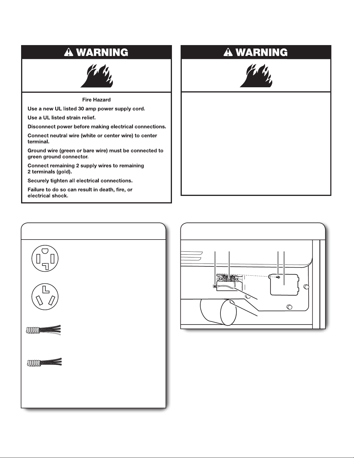
Use a UL Listed power supply cord kit marked for use with
clothes dryers. The kit should contain:
n A UL Listed 30 amp power supply cord, rated 120/240 volt
minimum. The cord should be type SRD or SRDT and be at
least 4 ft (1.22 m) long. The wires that connect to the dryer
must end in ring terminals or spade terminals with upturned
ends.
n A UL Listed strain relief.
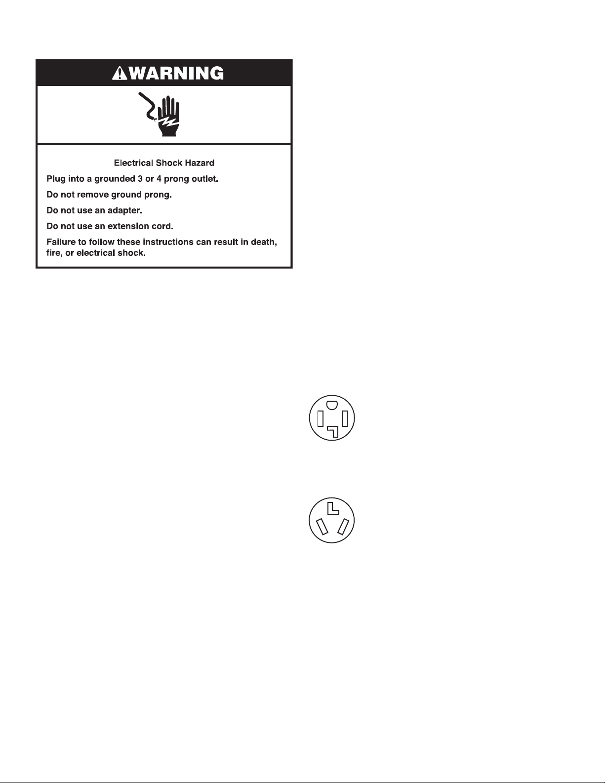
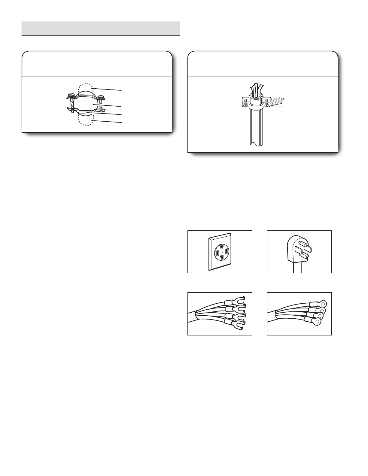
If your outlet looks like this:
Then choose a 4-wire power supply cord with ring
or spade terminals and UL Listed strain relief. The
4-wire power supply cord, at least 4 ft (1.22 m)
long, must have four 10-gauge copper wires and
match a 4-wire receptacle of NEMA Type 14-30R.
4-wire
receptacle
(14-30R)
The ground wire (ground conductor) may be either
green or bare. The neutral conductor must be
identied by a white cover.
If your outlet looks like this:
Then choose a 3-wire power supply cord with ring
or spade terminals and UL Listed strain relief. The
3-wire power supply cord, at least 4 ft (1.22 m) long,
must have three 10-gauge copper wires and match
a 3-wire receptacle of NEMA Type 10-30R.
3-wire
receptacle
(10-30R)
If connecting by direct wire (27" [69 cm] models only):
Power supply cable must match power supply (4-wire or 3-wire)
and be:
n Flexible armored cable or nonmetallic sheathed copper
cable (with ground wire), covered with exible metallic
conduit. All current-carrying wires must be insulated.
n 10-gauge solid copper wire (do not use aluminum).
n At least 5 ft (1.52 m) long.
11
Electrical Requirements,
120V Electric Models – U.S.A.
and Canada (24" [61 cm]
Models Only)
n It is recommended that a separate circuit breaker
serving only this appliance be provided.
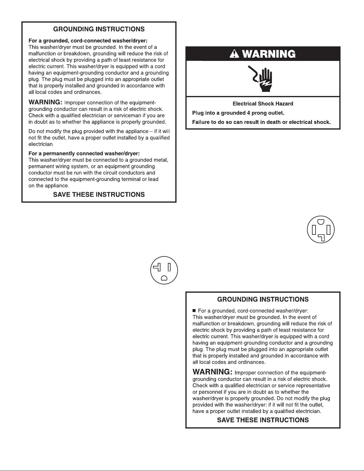
n 120V models are equipped with a power supply
cord having a 3 prong grounding plug intended
to be plugged into a 20 amp 5-20R wall receptacle.
n To minimize possible shock hazard, the cord
must be plugged into a mating, 3 prong,
grounding-type outlet, grounded in accordance
with local codes and ordinances. If a mating outlet is not
available, it is the personal responsibility and obligation
of the customer to have the properly grounded outlet installed
by a qualied electrician.
n If codes permit and a separate ground wire is used, it is
recommended that a qualied electrician determine that
the ground path is adequate.
n Check with a qualied electrician if you are not sure the
washer/dryer is properly grounded.
n Do not have a fuse in the neutral or ground circuit.
n 120 volt, 60 Hz, AC only, 20 amp fused electrical
supply is required. A time-delay fuse or circuit breaker
is recommended.
It is your responsibility:
n To contact a qualied electrical installer.
n To be sure that the electrical connection is adequate and in
conformance with the National Electrical Code, ANSI/NFPA
70 – latest edition or the Canadian Electrical Code, C22.1 –
latest edition and all local codes and ordinances.
A copy of the above code standards can be obtained from:
National Fire Protection Association, One Batterymarch Park,
Quincy, MA 02269 or Canadian Standards Association, 178
Rexdale Blvd., Toronto, ON M9W 1R3 CANADA.
n Do not use an extension cord.
12
5-20R
receptacle
Electrical Requirements,
240V Electric Models – Canada
It is your responsibility:
n To contact a qualied electrical installer.
n To be sure that the electrical connection is adequate and in
conformance with Canadian Electrical Code, C22.1 – latest
edition and all local codes. A copy of above codes standard
may be obtained from: Canadian Standards Association,
178 Rexdale Blvd., Toronto, ON M9W 1R3 CANADA.
n To supply the required 4-wire, single-phase, 120/240 volt,
60 Hz, AC only electrical supply on a separate 30 amp
circuit, fused on both sides of the line. A time-delay fuse
or circuit breaker is recommended. Connect to an individual
branch circuit.
n This dryer is equipped with a UL Listed
and/or CSA International Certied Power
Cord intended to be plugged into a standard
14-30R wall receptacle. The cord is 5 ft.
(1.52 m) long. Be sure wall receptacle is
within reach of dryer’s nal location.
If using a replacement power supply cord, it is recommended that
you use Power Supply Cord Replacement Part Number 9831317.
For further information, please reference service numbers located
in “Assistance or Service” section of your Use and Care Guide.
4-wire receptacle
(14-30R)
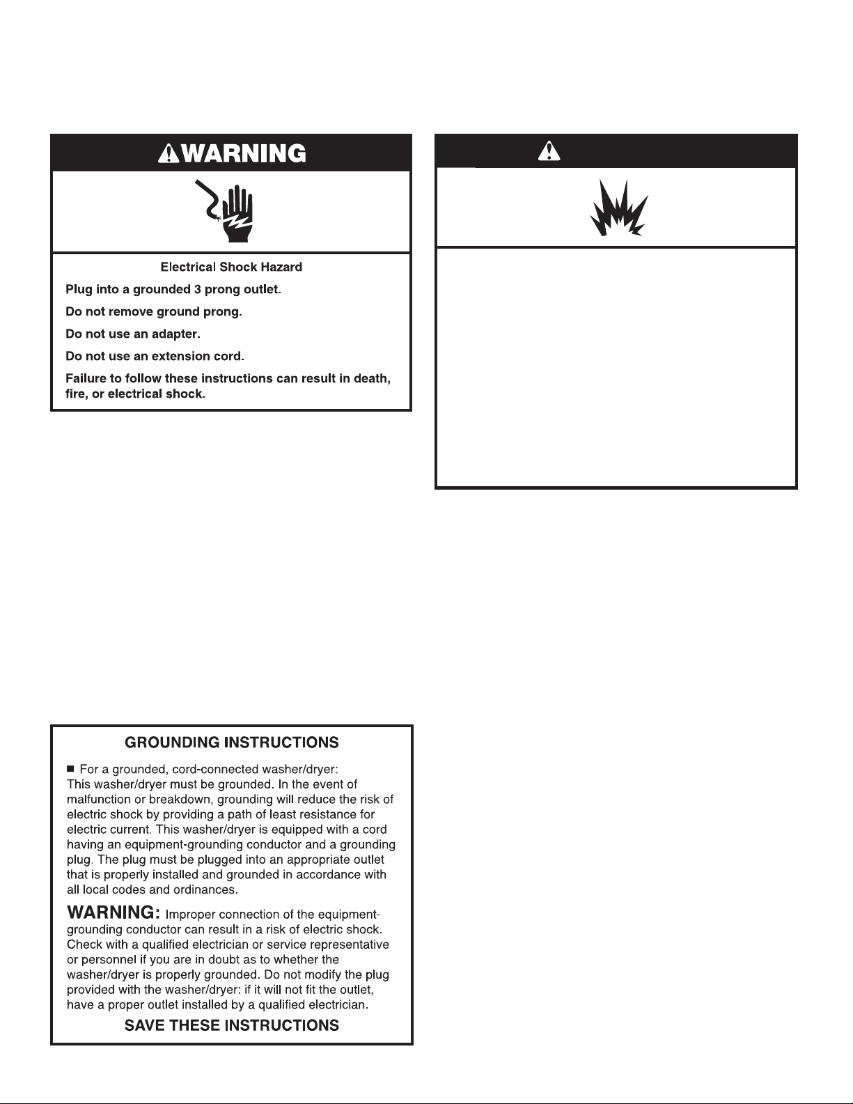
Electrical Requirements,
WARNING
Gas Supply Requirements,
Gas Models (27" [69 cm]
Models Only)
n This washer/dryer is equipped with a power supply cord
having a 3-prong grounding plug.
n To minimize possible shock hazard, the cord must be plugged
into a mating, 3 prong, grounding-type outlet, grounded in
accordance with local codes and ordinances. If a mating outlet
is not available, it is the personal responsibility and obligation
of the customer to have the properly grounded outlet installed
by a qualied electrician.
n If codes permit and a separate ground wire is used, it is
recommended that a qualied electrician determine that
the ground path is adequate.
n Do not ground to a gas pipe.
n Check with a qualied electrician if you are not sure the
washer/dryer is properly grounded.
n Do not have a fuse in the neutral or ground circuit.
n 120 volt, 60 Hz, AC only, 15 or 20 amp fused electrical
supply is required. A time-delay fuse or circuit breaker is
recommended. It is also recommended that a separate
circuit serving only this washer/dryer be provided.
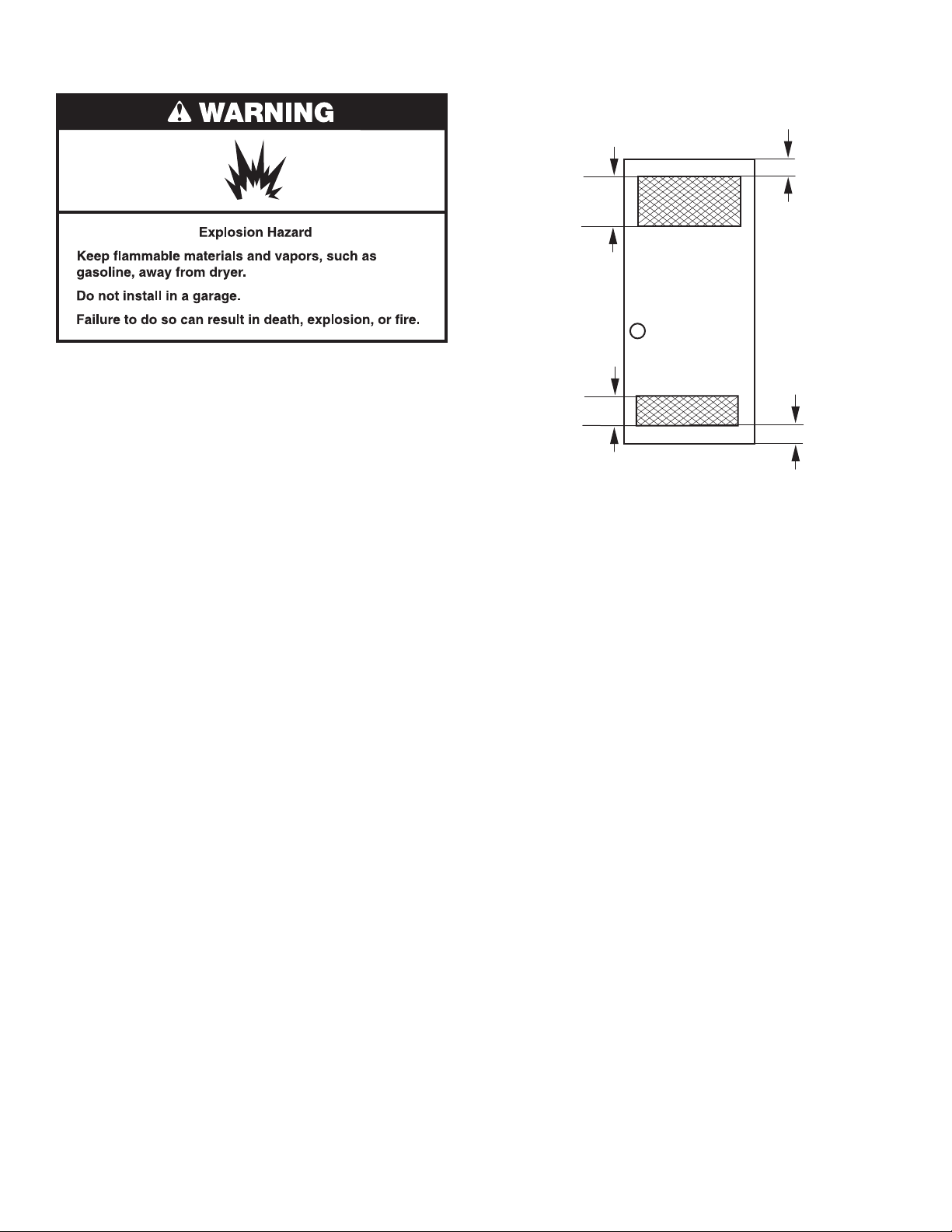
Gas Models (27" [69 cm]
Models Only)
Explosion Hazard
Use a new CSA International approved gas supply line.
Install a shut-off valve.
Securely tighten all gas connections.
If connected to propane, have a qualified person make
sure gas pressure does not exceed 13" (330 mm) water
column.
Examples of a qualified person include:
licensed heating personnel,
authorized gas company personnel, and
authorized service personnel.
Failure to do so can result in death, explosion, or fire.
GAS TYPE
Natural Gas:
This washer/dryer is equipped for use with natural gas. It is
certied by UL for use with propane gas with appropriate
conversion.
n Your washer/dryer must have the correct burner for the type
of gas in your home. Burner information is located on the
rating plate in the door well of your dryer. If this information
does not agree with the type of gas available, contact
your dealer or call the phone numbers referenced in the
“Assistance or Service” section of your Use and Care Guide.
Propane Gas Conversion:
IMPORTANT: Conversion must be made by a qualied
technician.
No attempt shall be made to convert the appliance from the gas
specied on the model/serial rating plate for use with a different
gas without consulting your gas company.
13
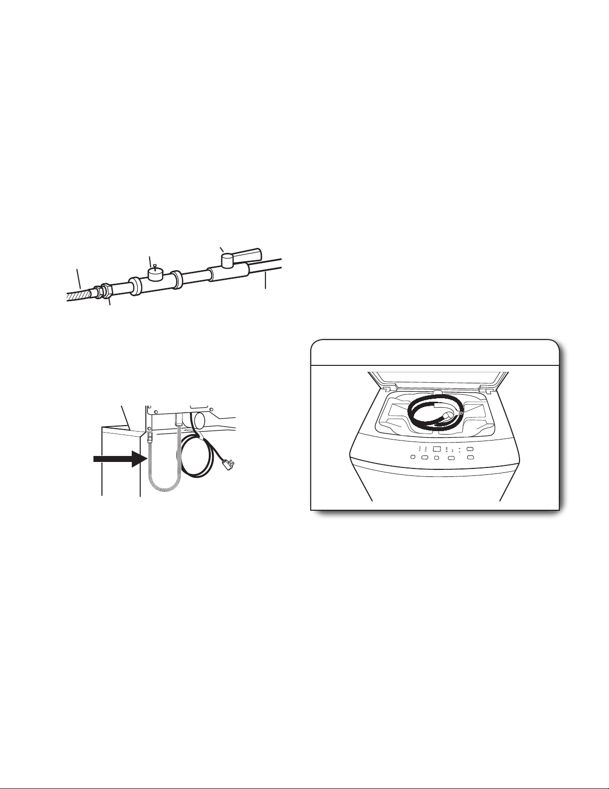
GAS SUPPLY LINE
■ Must include 1/8" NPT minimum plugged tapping accessible
for test gauge connection, immediately upstream of the gas
connection to the washer/dryer. See illustration below.
■ 1/2" IPS pipe is recommended.
■ Must include shut-off valve:
In the U.S.A.:
An individual manual shut-off valve must be installed within
six (6) ft. (1.8 m) of the washer/dryer in accordance with the
National Fuel Gas Code, ANSI Z223.1. The location should
be easy to reach for opening and closing.
In Canada:
An individual manual shut-off valve must be installed in
accordance with the B149.1, Natural Gas and Propane
Installation Code. It is recommended that an individual
manual shut-off valve be installed within six (6) ft. (1.8 m)
of the washer/dryer. The location should be easy to reach
for opening and closing.
E
C
A
D
B
A. 3/8" exible gas connector
B. 1/2" NPT adapter
C. 1/8" NPT minimum plugged tapping
D. 1/2" NPT gas supply line
E. Gas shut-off valve
This washer/dryer is equipped with its own permanent,
exible gas connector, design-certi ed by CSA International,
for connecting the washer/dryer to the gas supply line.
GAS SUPPLY CONNECTION REQUIREMENTS
■ Use the 1/2" NPT adapter between the gas supply line
and the exible gas connector on the washer/dryer.
■ Use only pipe-joint compound. Do not use TEFLON
®
tape.
BURNER INPUT REQUIREMENTS
Elevations up to 10,000 ft (3,048 meters):
■ The design of this washer/dryer is certi ed by CSA
International for use at altitudes up to 10,000 ft (3,048 m)
above sea level at the Btu rating indicated on the model/serial
number plate. Burner input adjustments are not required when
the washer/dryer is operated up to this elevation.
Elevations above 10,000 ft (3,048 meters):
■ When installed above 10,000 ft. (3,048 m), a 4% reduction of
the burner Btu rating shown on the model/serial number plate
is required for each 1,000 ft. (305 m) increase in elevation.
Gas supply pressure testing
■ The washer/dryer must be disconnected from the gas supply
piping system during pressure testing at pressures greater
than 1/2 psi.
Remove Foam Packing
(24" [61 cm] models)
1. Pull foam packing ring out of washer
Flexible gas connector
DRYER GAS CONNECTION
Option 1
Rigid gas supply line:
■ Connect your washer/dryer to the rigid gas supply line using
the 1/2" NPT adapter between the gas supply line and the
exible gas connector on the washer/dryer.
Option 2
Approved aluminum or copper tubing:
■ 3/8" approved aluminum or copper tubing is acceptable for
lengths under 20 ft. (6.1 m) if local codes and gas supplier permit.
■ If you are using natural gas, do not use copper tubing.
■ Lengths over 20 ft. (6.1 m) should use larger tubing and
a different size adapter tting.
■ If your washer/dryer has been converted to use propane gas, 3/8"
propane compatible copper tubing can be used. If the total length
of the supply line is more than 20 ft. (6.1 m), use larger pipe.
NOTE: Pipe-joint compounds that resist the action of propane
gas must be used. Do not use TEFLON
†®TEFLON is a registered trademark of Chemours.
14
®†
tape.
Open the washer lid. The latch under the dryer will keep
the lid open. Pull the foam packing ring and drain hose
out of the washer.
NOTE: Keep the foam ring and use it when transporting
your washer/dryer. This packing material is used to keep
the washer tub stable during transport.
Electrical Connection, 27" (69 cm) Electric Models (U.S.A. Only)
Power Supply Cord Direct Wire
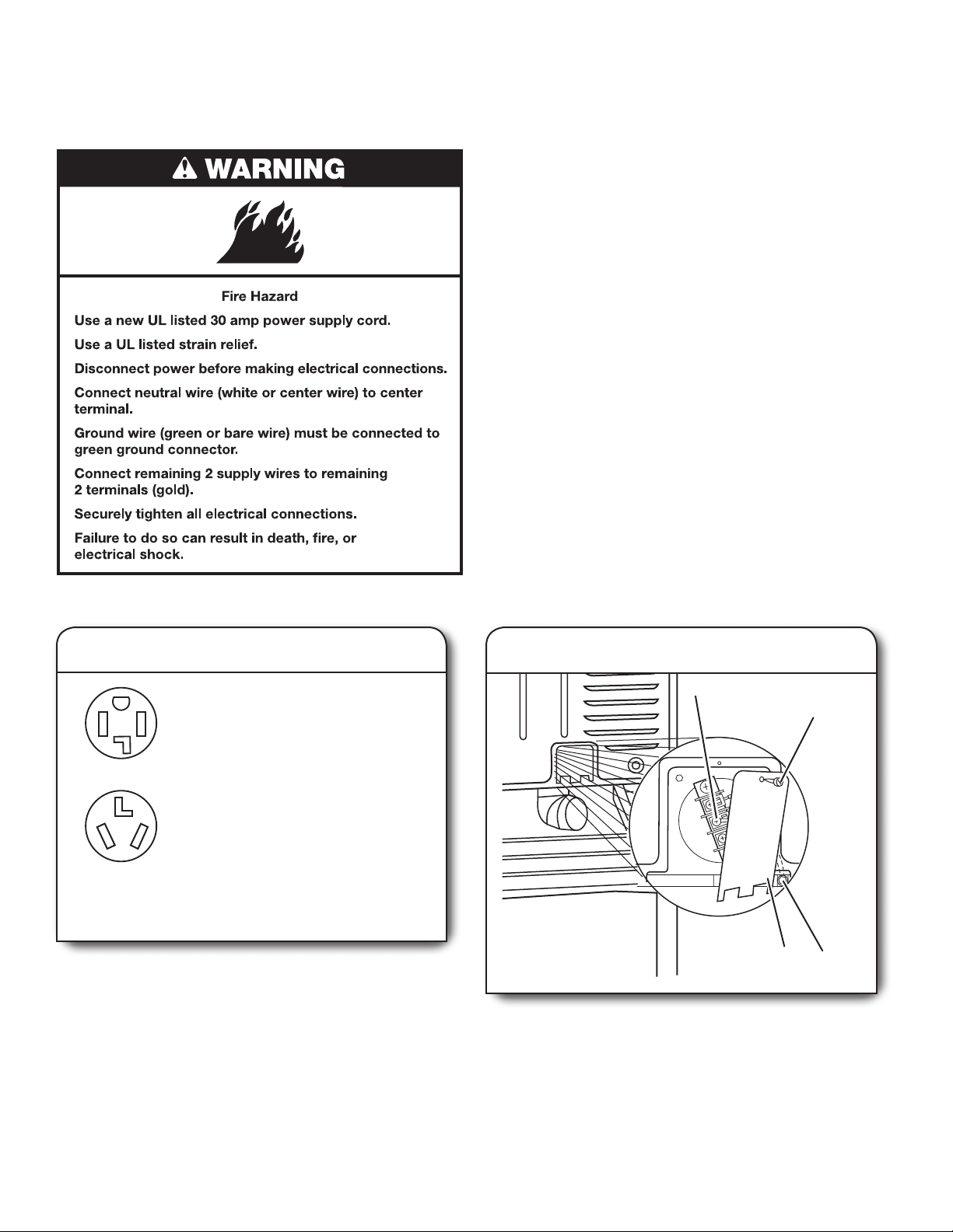
Fire Hazard
Use 10 gauge copper wire.
Use a UL listed strain relief.
Disconnect power before making electrical connections.
Connect neutral wire (white or center wire) to center
terminal.
Ground wire (green or bare wire) must be connected
to green ground connector.
Connect remaining 2 supply wires to remaining
2 terminals (gold).
Securely tighten all electrical connections.
Failure to do so can result in death, re, or
electrical shock.
Electrical Connection Options
1. Choose electrical connection type
Power supply cord 4-wire receptacle
(NEMA Type 14-30R): Go to “4-Wire
Power Supply Cord Connection.”
Then, go to “Venting Requirements.”
Power supply cord 3-wire receptacle
(NEMA Type 10-30R): Go to “3-Wire
Power Supply Cord Connection.”
Then go to “Venting Requirements.”
4-wire direct connection: Go to “4-Wire
Direct Wire Connection.” Then go to
“Venting Requirements.”
3-wire direct connection: Go to “3-Wire
Direct Wire Connection.” Then go to
“Venting Requirements.”
NOTE: If local codes do not permit connection of a
cabinet-ground conductor to neutral wire, go to “Optional
3-Wire Connection.” This connection may be used with
either a power supply cord or a direct wire connection.
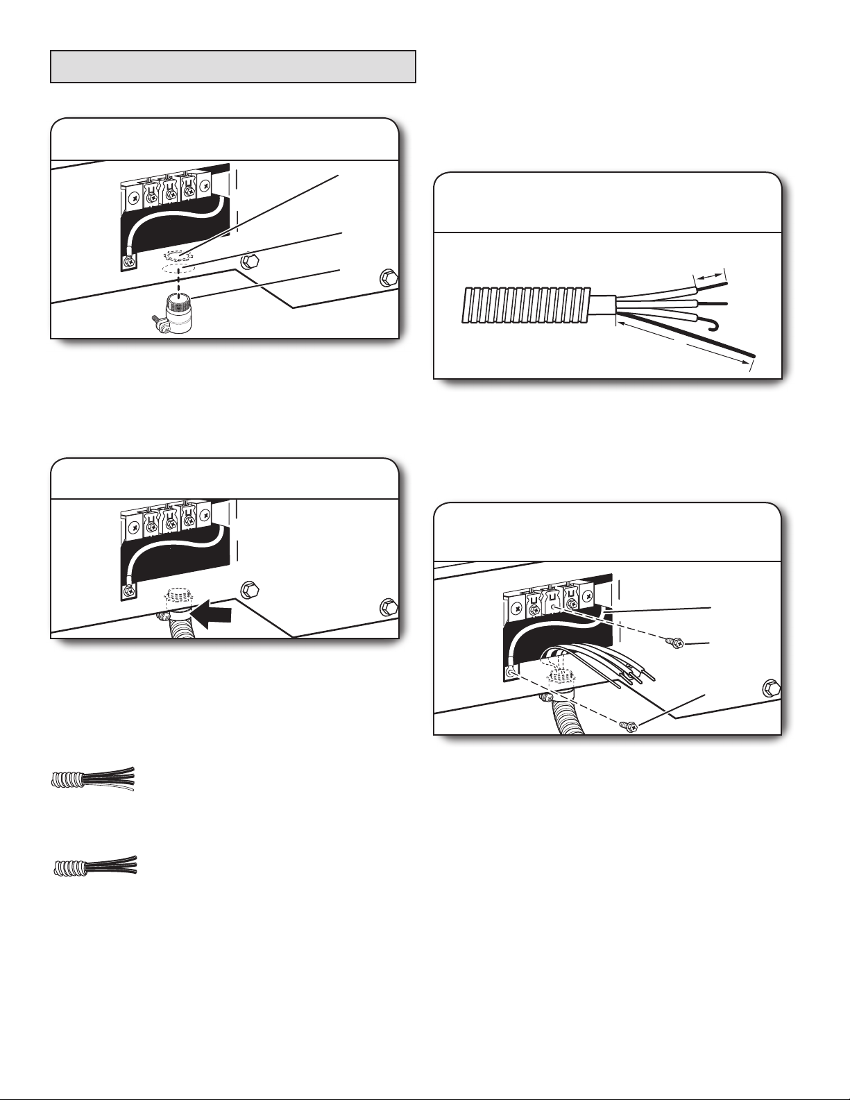
2. Remove terminal block cover
BC D
E
F
Before you start, disconnect power. Remove hold-down
screw (D) and terminal block cover (A).
A. Terminal block cover
B. External ground conductor screw
C. Center terminal block screw
D. Hold-down screw
E. Neutral ground wire
F. Hole below terminal block cover
A
15
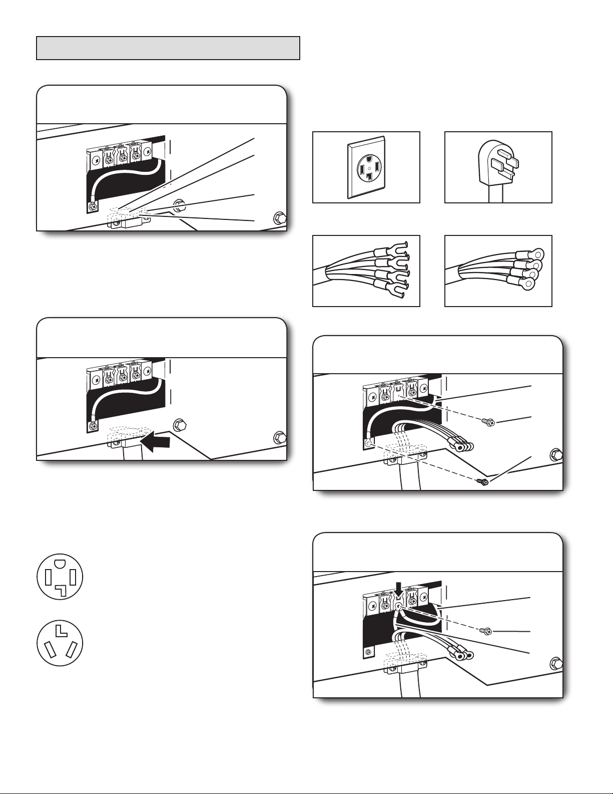
Power Supply Cord Connection
Power Supply Cord Strain Relief
1. Attach power supply cord
strain relief
A
B
C
D
Remove the screws from a 3/4" (19 mm) UL Listed strain
relief. Put the tabs of the two clamp sections (C) into the
hole below the terminal block opening (B) so that one tab
is pointing up (A) and the other is pointing down (D), and
hold in place. Tighten strain relief screws just enough to
hold the two clamp sections (C) together.
2. Attach power supply cord
to strain relief
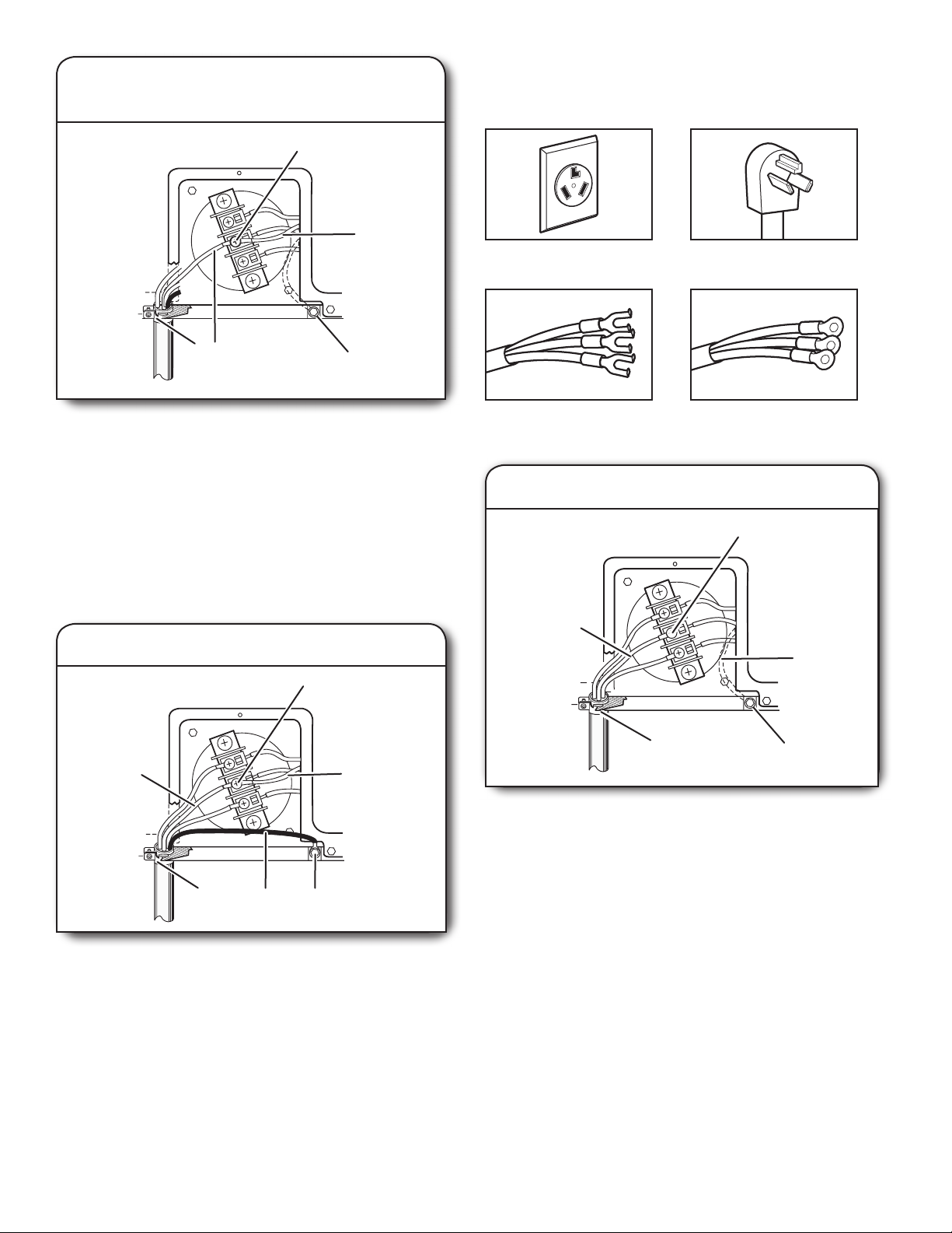
4-Wire Power Supply Cord Connection
IMPORTANT:
homes and where local codes do not permit the use of 3-wire
connections.
4-wire receptacle
(NEMA type 14-30R)
Spade terminals
with upturned ends
A 4-wire connection is required for mobile
4 prong plug
Ring terminals
1. Prepare to connect neutral
ground wire and neutral wire
Put power supply cord through the strain relief. Be sure that
the wire insulation on the power supply cord is inside the
strain relief. The strain relief should have a tight t with the
dryer cabinet and be in a horizontal position. Do not further
tighten strain relief screws at this point.
If your outlet looks like this:
Power supply cord 4-wire receptacle
(NEMA Type 14-30R):
Go to “4-Wire Power Supply Cord
Connection” on this page.
Power supply cord 3-wire receptacle
(NEMA Type 10-30R):
Go to “3-Wire Power Supply Cord
Connection” on page 17.
E
B
A
Remove center terminal block screw (B). Remove neutral
ground wire (E) from external ground conductor screw (A).
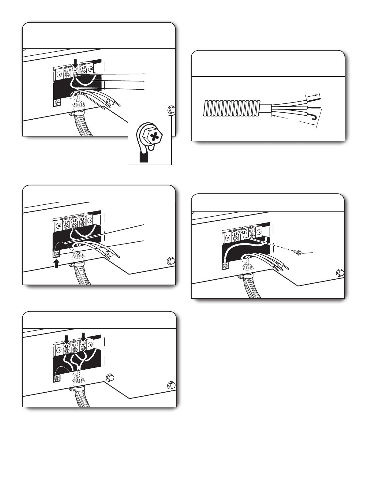
2. Connect neutral ground wire
and neutral wire
E
B
C
16
Connect neutral ground wire (E) and neutral wire (white or
center) (C) of power supply cord under center terminal block
screw (B). Tighten screw.
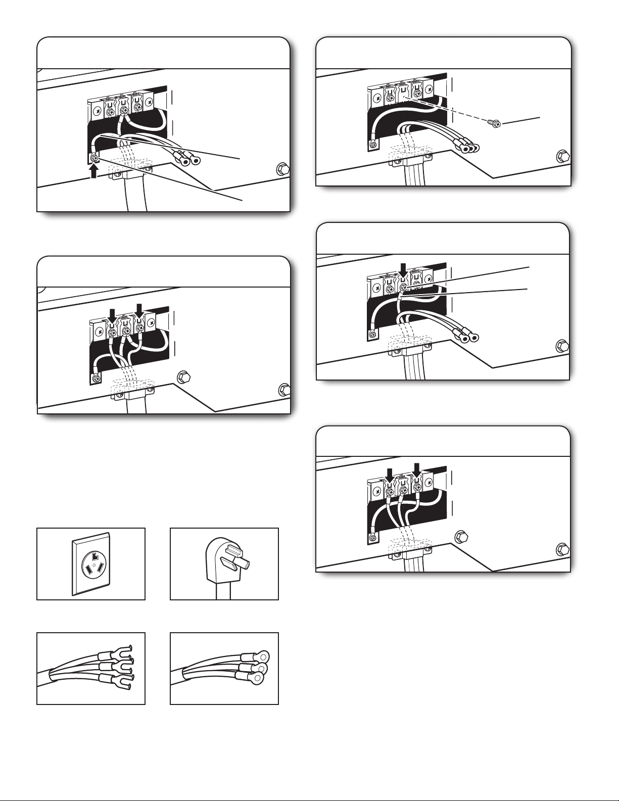
3. Connect ground wire
1. Remove center screw
B
F
A
Connect ground wire (F) (green or bare) of power supply cord
to external ground conductor screw (A). Tighten screw.
4. Connect remaining wires
Connect remaining wires to outer terminal block screws.
Tighten screws. Finally, reinsert tab of terminal block cover
into slot of dryer rear panel. Secure cover with hold-down
screw. Now, go to “Venting Requirements.”
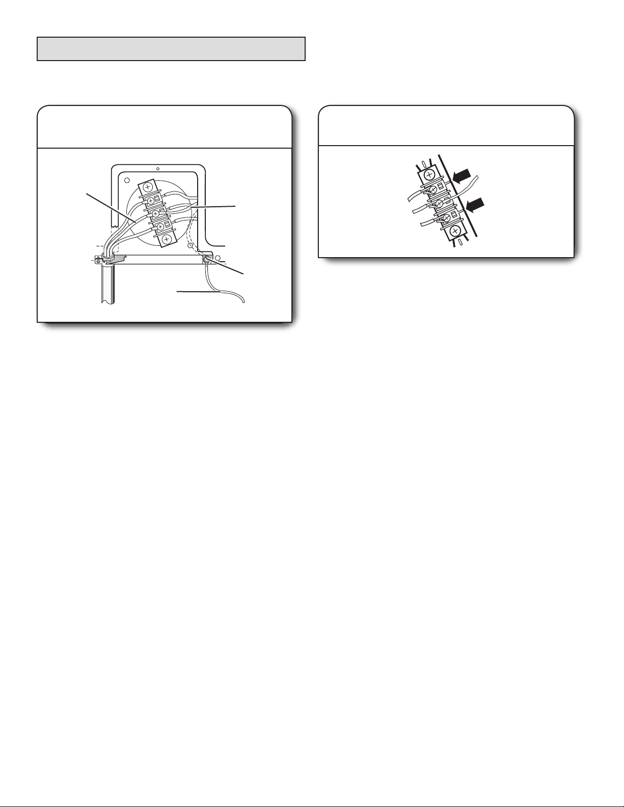
3-Wire Power Supply Cord Connection
IMPORTANT: Use where local codes permit connecting
cabinet-ground conductor to neutral wire.
Remove center terminal block screw (B).
2. Connect neutral wire
B
C
Connect neutral wire (white or center) (C) of power supply cord
to center terminal block screw (B). Tighten screw.
3. Connect remaining wires
3-wire receptacle
(NEMA type 10-30R)
Spade terminals
with upturned ends
3 prong plug
Ring terminals
Connect remaining wires to outer terminal block screws.
Tighten screws. Finally, reinsert tab of terminal block cover
into slot of dryer rear panel. Secure cover with hold-down
screw. Now, go to “Venting Requirements.”
17
Direct Wire Connection
Direct Wire Strain Relief
1. Attach direct wire strain relief
A
B
C
Unscrew the removable conduit connector (A) and any
screws from a 3/4" (19 mm) UL Listed strain relief. Put the
threaded section of the strain relief (C) through the hole below
the terminal block opening (B). Reaching inside the terminal
block opening, screw the removable conduit connector (A)
onto the strain relief threads.
2. Attach direct wire cable to strain relief
4-Wire Direct Wire Connection
IMPORTANT: A 4-wire connection is required for mobile
homes and where local codes do not permit 3-wire
connections.
1. Prepare your 4-wire cable for direct
connection
1"
(25 mm)
5"
(127 mm)
Direct wire cable must have 5 ft. (1.52 m) of extra length so
washer/dryer may be moved if needed.
Strip 5" (127 mm) of outer covering from end of cable,
leaving bare ground wire at 5" (127 mm). Cut 1½" (38 mm)
from remaining 3 wires. Strip insulation back 1" (25 mm).
Shape ends of wires into hooks.
Put direct wire cable through the strain relief. The strain
relief should have a tight t with the dryer cabinet and be in
a horizontal position. Tighten strain relief screw against the
direct wire cable.
If your wiring looks like this:
4-wire direct wire connection:
Go to “4-Wire Direct Wire Connection”
on this page.
3-wire direct wire connection:
Go to “3-Wire Direct Wire Connection”
on page 19.
2. Prepare to connect neutral ground
wire and neutral wire
E
B
A
Remove center terminal block screw (B). Remove neutral
ground wire (E) from external ground conductor screw (A).
18
3. Connect neutral ground wire
and neutral wire
3-Wire Direct Wire Connection
IMPORTANT: Use where local codes permit connecting
cabinet-ground conductor to neutral wire.
1. Prepare your 3-wire cable
B
E
C
for direct connection
1"
(25 mm)
3½"
(89 mm)
Connect neutral ground wire (E) and place
hooked end (hook facing right) of neutral
wire (white or center wire) (C) of direct
wire cable under center screw of terminal
block (B). Squeeze hooked ends together
and tighten screw.
4. Connect ground wire
F
A
Connect ground wire (green or bare) (F) of direct wire cable
to external ground conductor screw (A). Tighten screw.
Direct wire cable must have 5 ft. (1.52 m) of extra length so
washer/dryer may be moved if needed.
Strip 3½" (89 mm) of outer covering from end of cable. Strip
insulation back 1" (25 mm). If using 3-wire cable with ground
wire, cut bare wire even with outer covering. Shape wire ends
into hooks.
2. Remove center screw
B
Remove center terminal block screw (B).
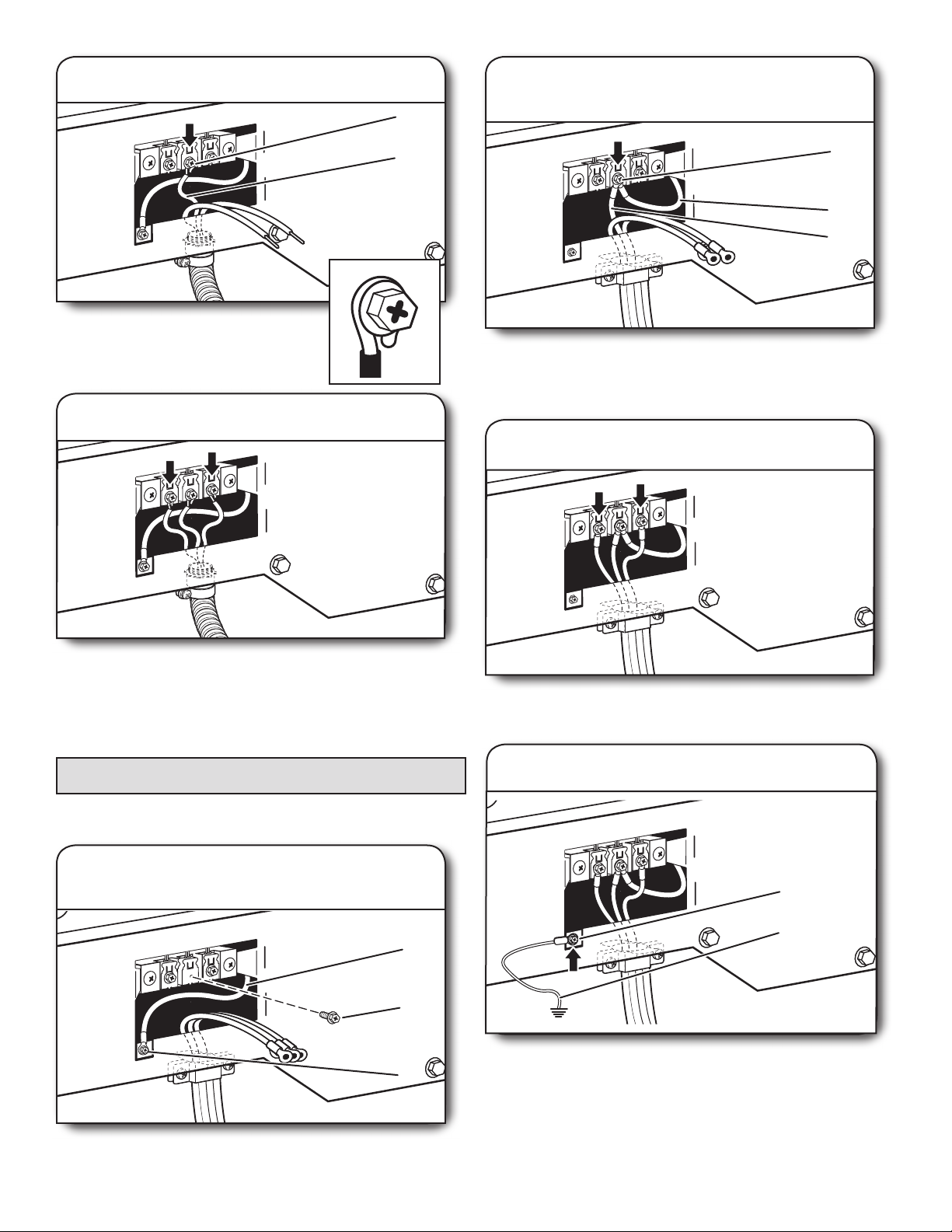
5. Connect remaining wires
Place hooked ends of remaining direct wire cable wires
under outer terminal block screws (hooks facing right).
Squeeze hooked ends together and tighten screws. Finally,
reinsert tab of terminal block cover into slot of dryer rear
panel. Secure cover with hold-down screw. Now, go to
“Venting Requirements.”
19
A
G
3. Connect neutral wire
2. Connect neutral ground wire
B
and neutral wire
Place hooked end of neutral wire (white or
center) (C) of direct wire cable under center
terminal block screw (B). Squeeze hooked
end together. Tighten screw.
4. Connect remaining wires
C
Connect neutral ground wire (E) and neutral wire (white or
center wire) (C) of power supply cord or cable under center
terminal block screw (B). Tighten screw.
B
E
C
3. Connect remaining wires
Place hooked ends of remaining direct wire cable wires
under outer terminal block screws (hooks facing right).
Squeeze hooked ends together and tighten screws. Finally,
reinsert tab of terminal block cover into slot of dryer rear
panel. Secure cover with hold-down screw. Now, go to
“Venting Requirements.”
Optional 3-Wire Connection
IMPORTANT: You must verify with a quali ed electrician that
this grounding method is acceptable before connecting.
1. Prepare to connect neutral
ground wire and neutral wire
E
B
A
Remove center terminal block screw (B). Remove neutral
ground wire (E) from external ground conductor screw (A).
20
Place remaining wires under outer terminal block screws
(hooks facing right). Tighten screws.
4. Connect external ground wire
Connect a separate copper ground wire (G) from the external
ground conductor screw (A) to an adequate ground. Finally,
reinsert tab of terminal block cover into slot of dryer rear
panel. Secure cover with hold-down screw. Now, go to
“Venting Requirements.”
Electrical Connection, 24" (61 cm) 240V Electric Models
(U.S.A. Only)
Power Supply Cord
Electrical Connection Options
1. Choose electrical connection type
Power supply cord 4-wire receptacle
(NEMA Type 14-30R): Go to “4-Wire
Power Supply Cord Connection.”
Then, go to “Venting Requirements.”
Power supply cord 3-wire receptacle
(NEMA Type 10-30R): Go to “3-Wire
Power Supply Cord Connection.”
Then go to “Venting Requirements.”
NOTE: If local codes do not permit connection of a
cabinet-ground conductor to neutral wire, go to “Optional
3-Wire Connection.”
2. Remove terminal block cover
A
B
D
C
Before you start, disconnect power. Remove hold-down
screw (B) and terminal block cover (C).
A. Center terminal block screw
B. Hold-down screw
C. Terminal block cover
D. External ground conductor screw
21
A
B
C
D
Power Supply Cord Connection
Power Supply Cord Strain Relief
1. Attach power supply cord
strain relief
Remove the screws from a 3/4" (19 mm) UL Listed strain
relief. Put the tabs of the two clamp sections (C) into the
hole below the terminal block opening (B) so that one tab
is pointing up (A) and the other is pointing down (D), and
hold in place. Tighten strain relief screws just enough to
hold the two clamp sections (C) together.
A. Strain relief tab pointing up
B. Hole below terminal block opening
C. Clamp section
D. Strain relief tab pointing down
2. Attach power supply cord
to strain relief
Put power supply cord through the strain relief. Be sure that
the wire insulation on the power supply cord is inside the
strain relief. The strain relief should have a tight t with the
dryer cabinet and be in a horizontal position. Do not further
tighten strain relief screws at this point.
4-Wire Power Supply Cord Connection
IMPORTANT: A 4-wire connection is required for mobile
homes and where local codes do not permit the use of
3-wire connections.
4-wire receptacle
(NEMA type 14-30R)
Spade terminals
with upturned ends
4 prong plug
Ring terminals
22
1. Connect neutral ground wire
A
B
B
and neutral wire
3-Wire Power Supply Cord Connection
IMPORTANT: Use where local codes permit connecting
cabinet-ground conductor to neutral wire.
E
D
Remove center terminal block screw. Remove neutral ground
wire from external ground conductor screw. Connect neutral
ground wire and the neutral wire (white or center wire)
of power supply cord under center terminal block screw.
Tighten screw.
A. Center terminal block screw
B. Neutral ground wire
C. External ground conductor screw – Dotted
line shows position of NEUTRAL ground
wire before being moved to center terminal
block screw.
D. Neutral wire (white or center wire)
E. 3/4" (19 mm) UL Listed strain relief
C
2. Connect ground wire
3-wire receptacle
(NEMA type 10-30R)
Spade terminals
with upturned ends
1. Connect neutral wire
A
3 prong plug
Ring terminals
B
C
A
F
Connect ground wire (green or bare) of power supply cord
to external ground conductor screw. Tighten screw.
A. Neutral wire (white or center wire)
B. Center terminal block screw
C. Neutral ground wire
D. External ground conductor screw
E. Ground wire (green or bare) of power
supply cord
F. 3/4" (19 mm) UL Listed strain relief
Connect the other wires to outer terminal block screws. Tighten
screws. Tighten strain relief screws. Insert tab of terminal block
cover into slot of dryer rear panel. Secure cover with hold-down
screw. Now go to “Venting Requirements.”
E
C
D
E
Loosen or remove center terminal block screw. Connect neutral
wire (white or center wire) of power supply cord to the center
terminal screw of the terminal block. Tighten screw.
A. Neutral wire (white or center wire)
B. Center terminal block screw
C. Neutral ground wire
D. External ground conductor screw
E. 3/4" (19 mm) UL Listed strain relief
Connect the other wires to outer terminal block screws. Tighten
screws. Tighten strain relief screws. Insert tab of terminal block
cover into slot of dryer rear panel. Secure cover with hold-down
screw. Now go to “Venting Requirements.”
D
23
Optional 3-Wire Connection
Use for power supply cord where local codes do not permit
connecting cabinet-ground conductor to neutral wire.
1. Connect neutral ground wire
and neutral wire
A
B
C
D
Remove center terminal block screw. Remove neutral ground
wire from external ground conductor screw. Connect neutral
ground wire and the neutral wire (white or center wire) of
power supply cord under center terminal block screw.
Tighten screw.
A. Neutral wire (white or center wire)
B. Neutral ground wire
C. External ground conductor screw – Dotted
line shows position of NEUTRAL ground
wire before being moved to center terminal
block screw.
D. Grounding path determined by a quali ed
electrician
2. Connect remaining wires and
connect separate ground wire
Connect the other wires to outer terminal block screws.
Tighten screws. Tighten strain relief screws. Connect a
separate copper ground wire from the external ground
conductor screw to an adequate ground. Insert tab
of terminal block cover into slot of dryer rear panel.
Secure cover with hold-down screw. Now go to
“Venting Requirements.”
24
Venting
Venting Requirements
WARNING: To reduce the risk of re, this dryer MUST BE
EXHAUSTED OUTDOORS.
IMPORTANT: Observe all governing codes and ordinances.
Dryer exhaust must not be connected into any gas vent,
chimney, wall, ceiling, attic, crawlspace, or a concealed space
of a building. Only rigid or exible metal vent shall be used for
exhausting.
4"
(102 mm)
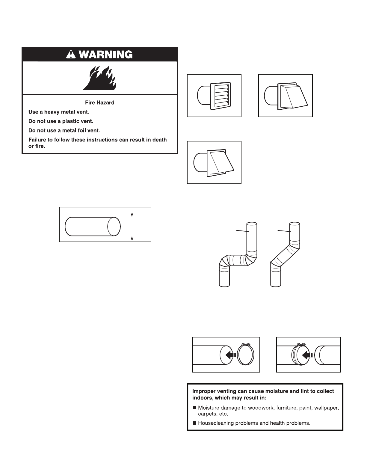
Exhaust hoods:
n Must be at least 12" (305 mm) from ground or any object
that may obstruct exhaust (such as owers, rocks, bushes,
or snow).
Recommended Styles:
Louvered hood Box hood
Acceptable Style:
Angled hood
Elbows:
n 45° elbows provide better airow than 90° elbows.
Good
Better
4" (102 mm) heavy metal exhaust vent
n Only a 4" (102 mm) heavy metal exhaust vent and clamps
may be used.
n Do not use plastic or metal foil vent.
Rigid metal vent:
n Recommended for best drying performance and to avoid
crushing and kinking.
Flexible metal vent: (Acceptable only if accessible to clean)
n Must be fully extended and supported in nal dryer location.
n Remove excess to avoid sagging and kinking that may result
in reduced airow and poor performance.
n Do not install in enclosed walls, ceilings, or oors.
n The total length should not exceed 7¾ ft. (2.4 m).
NOTE: If using an existing vent system, clean lint from entire
length of the system and make sure exhaust hood is not plugged
with lint. Replace plastic or metal foil vents with rigid metal
or exible metal vents. Review “Vent System Chart” and, if
necessary, modify existing vent system to achieve best drying
performance.
Clamps:
n Use clamps to seal all joints.
n Exhaust vent must not be connected or secured with screws
or other fastening devices that extend into interior of duct
and catch lint. Do not use duct tape.
See “Venting Kits” for more information.
25
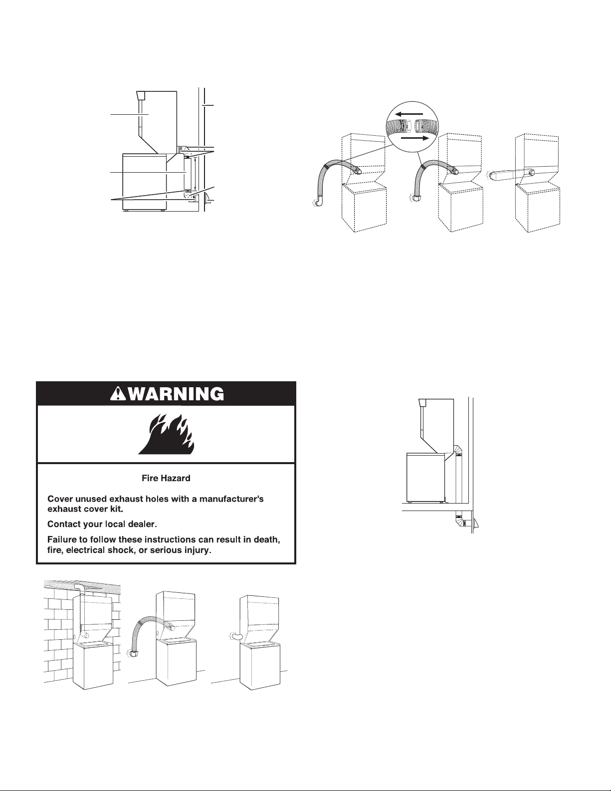
Plan Vent System
AB
C
Recommended exhaust installations
Typical installations vent the washer/dryer from the rear. Other
installations are possible.
A
B
C
D
E
F
G
H
Alternate installations for close clearances
Venting systems come in many varieties. Select the type best
for your installation. Three close-clearance installations are
shown. Refer to the manufacturer’s instructions.
A. Dryer
B. Rigid metal or exible metal vent
C. Clamps
D. Wall
E. Elbow
F. Clamps
G. Elbow
H. Exhaust hood
Optional exhaust installations:
24" (61 cm) washer/dryer models can be converted to exhaust
out the right or left side. To convert the washer/dryer, use
Side Exhaust Kit Part Number 279823. If your washer/dryer
was previously exhausted from the right or left side, it can be
converted to rear exhaust by using standard offset connections.
To cover the hole in the side, the following plug can be added:
692790 (white)
Follow the instructions in the kit to install. The kit is available
from the dealer from whom you purchased your washer/dryer.
ABC
A. Loop system with standard elbows
B. Loop system with one offset and one standard elbow
C. Vent system with one periscope (2" [51 mm] clearance)
Venting Kits
For more information, call 1-866-698-2538, or visit us
at www.whirlpool.com. In Canada, call 1-800-688-2002
or visit us at www.whirlpool.ca.
Special provisions for mobile home installations:
The exhaust vent must be securely fastened to a noncombustible
portion of the mobile home structure and must not terminate
beneath the mobile home. Terminate the exhaust vent outside.
A. Standard rear offset exhaust installation
B. Rear exhaust for offset close-clearance connection
C. Left- or right-side exhaust installation (24" [61 cm]
models only)
26
Determine vent path:
■ Select route that will provide straightest and most direct
path outdoors.
■ Plan installation to use fewest number of elbows and turns.
■ When using elbows or making turns, allow as much room
as possible.
■ Bend vent gradually to avoid kinking.
■ Use as few 90° turns as possible.
Determine vent length and elbows needed for best
drying performance:
n Use following Vent System Chart to determine type of vent
material and hood combinations acceptable to use.
NOTE: Do not use vent runs longer than those speci ed
in Vent System Chart. Exhaust systems longer than those
speci ed will:
n Shorten life of dryer.
n Reduce performance, resulting in longer drying times
and increased energy usage.
The Vent System Chart provides venting requirements that
will help achieve best drying performance.
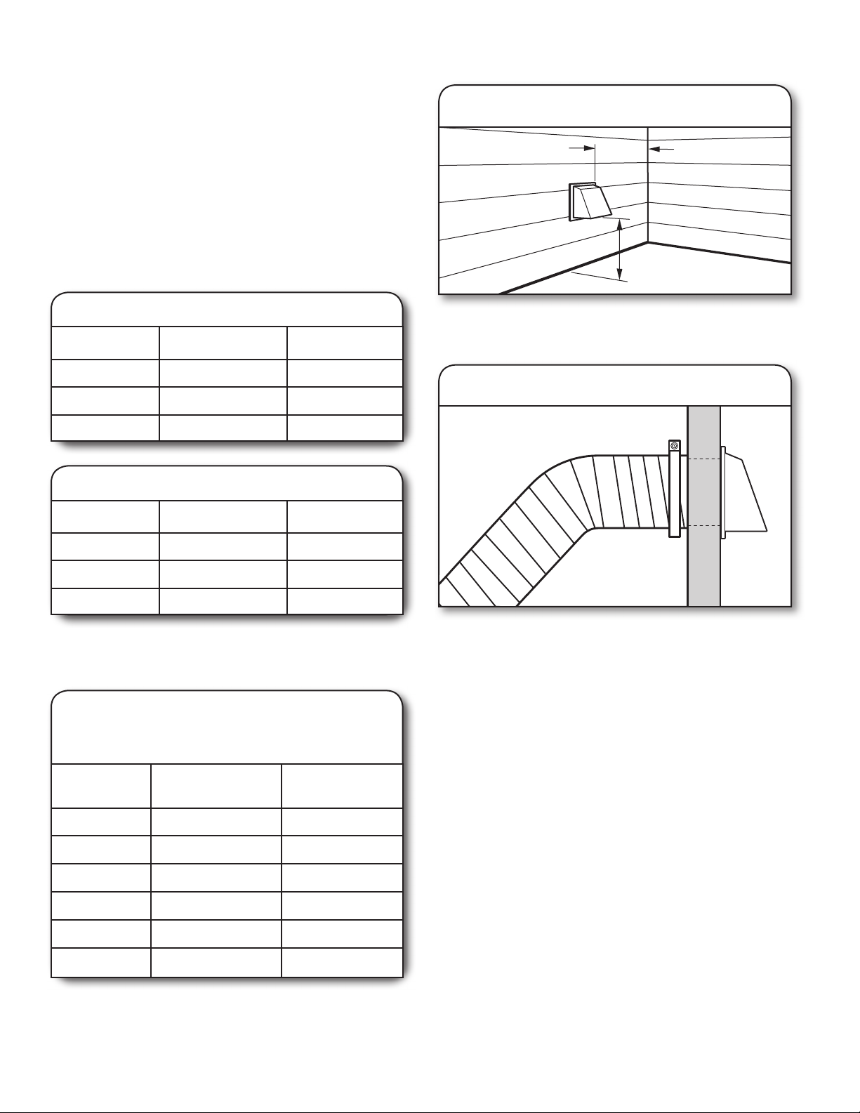
Install Vent System
1. Install exhaust hood
12" min.
(305 mm)
12" min.
(305 mm)
Vent System Chart, 27" (69 cm) Models
Number of 90°
turns or elbows
0 Rigid metal
1
2
Type
of vent
Rigid metal
Rigid metal
Angled
hoods
35 ft. (10.7 m)
27 ft. (8.2 m)
19 ft. (5.8 m)
Vent System Chart, 24" (61 cm) Models
Number of 90°
turns or elbows
0 Rigid metal
1
2
NOTE: Side exhaust installations (24" [61 cm] models only)
have a 90º turn inside the dryer. To determine maximum
exhaust length, add one 90º turn to the chart.
Type
of vent
Rigid metal
Rigid metal
Angled
hoods
36 ft. (11.0 m)
26 ft. (7.9 m)
16 ft. (4.9 m)
Vent System Chart,
27" (69 cm) Long Vent Models
WETLV27H and WGTLV27H (U.S. Only)
Install exhaust hood and use caulking compound to seal
exterior wall opening around exhaust hood.
2. Connect vent to exhaust hood
Vent must t inside the exhaust hood. Secure vent to exhaust
hood with 4" (102 mm) clamp. Run vent to dryer location using
straightest path possible. Avoid 90° turns. Use clamps to seal
all joints. Do not use duct tape, screws, or other fastening
devices that extend into interior of vent to secure vent,
because they can catch lint.
Number of
90° turns
or elbows
0 Rigid metal
1
2
3 Rigid metal
4 Rigid metal
5 Rigid metal
Type
of vent
Rigid metal
Rigid metal
Angled
hoods
125 ft. (38.1 m)
115 ft. (35.1 m)
105 ft. (32.0 m)
95 ft. (29.0 m)
85 ft. (25.9 m)
75 ft. (22.9 m)
27
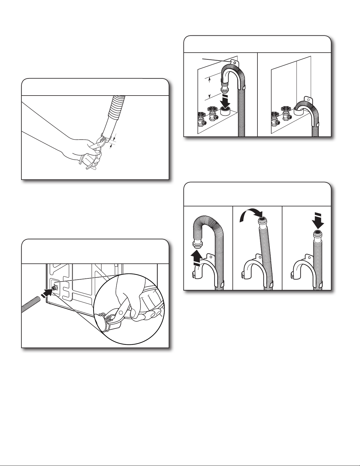
Connect Drain Hose
Proper connection of the drain hose protects your oors
from damage due to water leakage. To keep the drain hose
from coming off or leaking, it must be installed according
to the following instructions:
IMPORTANT: To ensure proper installation, this procedure
must be followed exactly.
3. Place drain hose in standpipe
Drain
hose form
1. Attach clamp to drain hose
¼"
1/4"
(6.4 mm)
6.4 mm)
(
Check the drain hose to see whether it is the proper length.
Wet the inside of the straight end of the drain hose with tap
water.
IMPORTANT: Do not use any lubricant other than water.
Squeeze ears of the silver double-wire clamp with pliers to
open. Place clamp over the straight end of the drain hose 1/4"
(6.4 mm) from the end.
2. Attach drain hose to drain connector
(27" [69 cm] model shown)
4.5"
(114 mm)
Place hose into standpipe (shown in picture) or over side
of laundry tub.
IMPORTANT: 4.5" (114 mm) of drain hose should be inside
standpipe; do not force excess hose into standpipe or lay
on bottom of laundry tub. Drain hose form must be used.
4. Remove drain hose form
( oor drain installations only)
The appearance of the
24" (61 cm) model will vary
Open clamp. Twist hose back and forth while pushing onto
drain connector at the lower left (27" [69 cm] models) or lower
center (24" [61 cm] models) portion of the rear of the washer/
dryer. Continue until hose contacts the ribbed stops on the
cabinet. On 27" (69 cm) models, place clamp over the area
on the hose marked “CLAMP.” On 24" (61 cm) models, place
clamp over the smooth area on the hose between the two ribs.
Release clamp.
28
For oor drain installations, you will need to remove the drain
hose form from the end of the drain hose. You may need
additional parts with separate directions. See “Tools and Parts.”
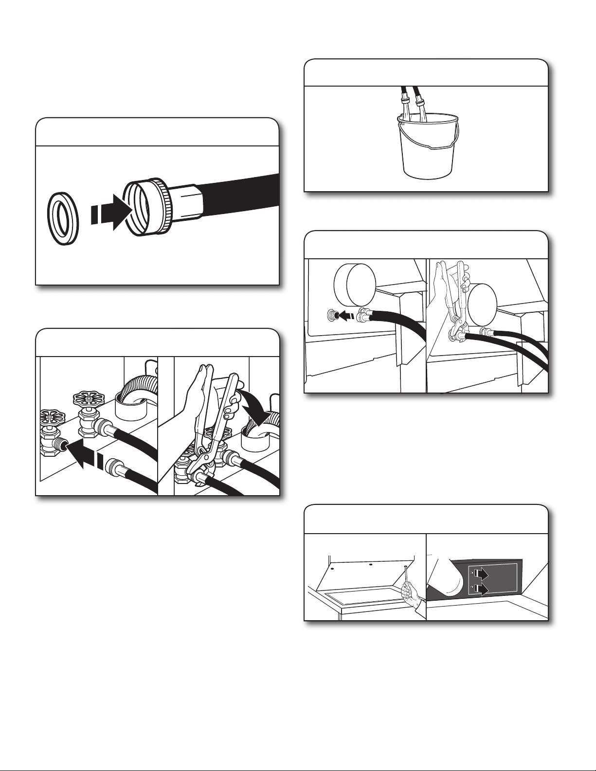
Connect Inlet Hoses
Washer must be connected to water faucets with new inlet
hoses with at washers (not provided). Do not use old hoses.
NOTE: Both hoses must be attached and have water owing
to inlet valves. If you are only connecting to a cold water
faucet, you must use a Y-adapter (not included).
1. Insert washer into each hose
3. Clear water lines
Run water for a few seconds through hoses into a laundry tub,
drainpipe, or bucket to prevent clogs. Water should run until clear.
Washer Coupling
Insert a new at washer into each end of the inlet hoses
(not provided). Firmly seat the washers in the couplings.
2. Connect inlet hoses to water faucets
Attach hose to hot water faucet. Screw on coupling by hand
until it is seated on washer. Use pliers to tighten couplings an
additional two-thirds turn. Repeat this step with second hose
for cold water faucet.
IMPORTANT: Do not overtighten or use tape or sealants on
valve when attaching to faucets or washer. Damage can result.
HELPFUL TIP: Make note of which hose is connected to hot
water to help in attaching hoses to washer correctly. In most
standard con gurations, hoses will cross over each other
when attached correctly.
4. Connect inlet hoses to washer
Attach hot water hose to the right-hand (red) inlet valve.
Screw coupling by hand until it is snug. Use pliers to tighten
couplings an additional two-thirds turn. Repeat with cold
water inlet valve (left-hand [blue] inlet valve).
IMPORTANT: To reduce risk of hose failure, replace the hoses
every 5 years. Record hose installation or replacement dates
for future reference.
n
Periodically inspect and replace hoses if bulges, kinks, cuts,
wear, or leaks are found.
5.
M
ove washer/dryer to nal location
Outer Access Panel
(27" [69 cm] model shown)
Inner Access Panel
(27" [69 cm] models only)
If you are working in a closet or recessed area: move the
washer/dryer into its nal location and remove cardboard
from under washer/dryer. Remove the outer access panel
by removing two (24" [61 cm] models) or three (27" [69 cm]
models) Phillips-head screws and one bumper (27" [69 cm]
models only), located at the top of the access panel. Remove
inner access panel (27" [69 cm] models only) by removing
cover and two screws. Set panels, screws, inner access panel
cover, and bumper aside. Complete hookup of water hoses
and vent. Replace access panels upon completion of
washer/dryer installation.
29
 Loading...