


S E R V I C E |
Whirlpool Europe |
Customer Services |
ADG 934 WH
Service Manual
Dishwasher integratable ADG 934 WH
Model |
ADG 934 WH |
|
Version |
8542 934 15010 |
Page |
|
Technical data |
2 - 4 |
|
Spare part list |
5 - 6 |
|
Exploded view |
7 - 8 |
|
Circuit diagram |
9 |
|
Program diagram |
10 |
|
Text/Legend |
11 - 19 |
|
Family |
A3 |
This documentation is only intended for qualified technicians who are aware of the respec-
tive safety regulations. |
|
Date: 18.03.1996 |
Subject to modification |
Document-No.: 4812 718 11658 |
|

18.03.1996 / Page 2 |
Whirlpool Europe |
|
S E R V I C E |
Doc. No: 4812 718 11658 |
Customer Service |
||
|
|
|
|
Technical data
Dimension
Height |
82,0-87,0 |
cm |
Width |
59,5 |
cm |
Depth |
57,0 |
cm |
Weight |
~ 55,0 |
kg |
Wooden door |
|
|
Thickness min.. |
16 |
mm |
Thickness max. |
25 |
mm |
Width min. |
592 |
mm |
Width max. |
595 |
mm |
Height min. |
571,5 |
mm |
Height max. |
604 |
mm |
Weight max. |
5,5 |
kg |
Max. stick out over lower |
|
|
edge of appliance door |
90 |
mm |
Specification (normal program) |
|
|
Capacity |
12 |
standard |
|
|
setting pl. |
Water consumption |
22 |
l |
Energy consumption |
1,5 |
kWh |
Program time |
~ 82 |
min |
Noise level |
54 |
db (A) |
Detergent consumption |
25 |
ml |
Salt consumption |
|
|
by 21˚ dh |
<20 |
g |
Hot water connect. up to |
60 |
˚C |
Alarms |
|
|
Refill salt |
|
|
Program information |
|
|
Pre rinse / pre wash |
|
|
Main wash |
|
|
Drying |
|
|
End |
|
|
Start indicator |
|
|
Volume (normal program) |
|
|
Water |
Volume |
Level |
Regeneration |
0,3 l |
15 mm |
Back rinse 3x |
1,0 l |
68 mm |
Prewash |
5,0 l |
125 mm |
Main wash |
6,0 l |
129 mm |
Intermediate rinse 1 |
5,0 l |
125 mm |
Clear rinse |
5,0 l |
125 mm |
Safety / overflow |
8,5 l |
141 mm |
Measuring the level
Remove the coarse sieve, put in a measuring meter into the sump, measure the height of the water level.
Detergent max. |
|
|
Pre-wash |
10 |
cm3 |
Main-wash |
45 |
cm3 |
Rinse aid |
125 |
cm3 |
6 Dosage steps |
1 - 6 |
cm3 |
Water softener |
|
|
Saltcontainer |
2 |
kg |
Resin container |
900 |
cm3 |
Regeneration dosage |
300 |
cm3 |
Water pressure |
|
|
Inlet pressure |
0,3-10 |
bar |
Spray pump pressure |
0,4 |
bar |
Rotations |
|
|
Spray pump motor |
2800 |
RPM |
Drain pump motor |
2800 |
RPM |
Spray arm lower |
~ 30 |
RPM |
Spray arm upper |
~ 35 |
RPM |
Ceiling rotor |
~ 60 |
RPM |
Flow rates / Inlet volume |
|
|
Flow meter (at 0,3 bar |
|
|
= quantity 1,1 l/min) |
208 |
lmp/l |
Spray pump |
~ 70 |
l/min |
Drain pump |
16 |
l/min |
Pump height max. |
1,3 |
m |
Inlet valve |
4,5 |
l/min |
Valve for sieve |
8 |
l/min |
Spray arm lower |
33 |
l/min |
Sprayarm upper |
30 |
l/min |
Ceiling rotor |
8 |
l/min |
Water distribution |
|
|
Fine sieve |
100 |
% |
Self cleaning |
|
|
micro filter |
~ 32 |
% |

S E R V I C E
Technical data
Whirlpool Europe |
18.03.1996 / Page 3 |
Customer Service |
Doc. No: 4812 718 11658 |
|
|
Electrical data |
|
|
Base data |
|
|
Voltage |
230 |
V |
Frequency |
50 |
Hz |
Total power |
~ 3 |
kW |
Fuse |
13 |
A |
Motor |
|
|
Spray pump motor |
|
|
Voltage |
220/230 |
V |
Power consumption |
~190 |
W |
HI |
69 |
Ω |
HA |
36,2 |
Ω |
Capacitor |
4 |
μ F |
Drain pump motor |
|
|
Voltage |
220/240 |
V |
Resistance |
146 |
Ω |
Heating |
|
|
1 Element system |
|
|
Voltage |
240 |
V |
Power consumption |
2800 |
W |
Resistance |
9,3 - 10 |
Ω |
Heating speed |
~ 2,5 |
˚C/min |
Temperature on surface |
~ 115 |
˚C |
Double safety thermostat |
|
|
self reset |
85 |
˚C |
Potentiometer |
|
|
Position 0 |
2,0 |
kΩ |
Position 1 |
4,3 |
kΩ |
Position 2 |
9,0 |
kΩ |
Position 3 |
13,3 |
kΩ |
Position 4 |
17,5 |
kΩ |
Position 5 |
22,2 |
kΩ |
Position 6 |
24,2 |
kΩ |
Water valves |
|
|
Single valve at inlet hose |
|
|
Voltage |
220/240 |
V |
Frequency |
50/60 |
Hz |
Resistance |
3,67 |
kΩ |
Regenerating valve |
|
|
Voltage |
220/240 |
V |
Frequency |
50/60 |
Hz |
Resistance |
3,13 |
kΩ |
Valve for sieve |
|
|
Voltage |
220/240 |
V |
Frequency |
50/60 |
Hz |
Resistance |
3,83 |
kΩ |
Coil of dispenser |
|
|
Voltage |
220/240 |
V |
Frequency |
50/60 |
Hz |
Resistance |
1,43 |
kΩ |
Relay |
|
|
Heating relay |
|
|
Voltage |
220/240 |
V |
Frequency |
50/60 |
Hz |
Resistance |
5,5 |
kΩ |
Reedcontact |
|
|
flow meter |
|
|
salt control |
|
|
NTC |
|
|
15 ˚C |
75 kΩ |
|
20 ˚C |
62 kΩ |
|
30 ˚C |
43 kΩ |
|
40 ˚C |
28 kΩ |
|
50 ˚C |
19 kΩ |
|
60 ˚C |
13 kΩ |
|
70 ˚C |
9 kΩ |
|
80 ˚C |
6 kΩ |
|
85 ˚C |
5 kΩ |
|
18.03.1996 / Page 4 |
Whirlpool Europe |
|
S E R V I C E |
Doc. No: 4812 718 11658 |
Customer Service |
||
Technical data |
|
|
|
Regeneration |
|
|
|
Volume |
300 |
|
cm3 |
Position 0 |
|
|
|
after wash cycles |
-- |
|
|
water hardness |
0-5 |
|
˚dh |
|
0-0,9 |
|
mmol/l |
Position 1 |
0-9 |
|
˚Fh |
|
|
|
|
after wash cycles |
6-8 |
|
|
water hardness |
6-10 |
|
˚dh |
|
1-1,8 |
|
mmol/l |
Position 2 |
10-18 |
|
˚Fh |
|
|
|
|
after wash cycles |
5-6 |
|
|
water hardness |
11-15 |
|
˚dh |
|
1,9-2,7 |
|
mmol/l |
Position 3 |
19-27 |
|
˚Fh |
|
|
|
|
after wash cycles |
4 |
|
|
water hardness |
16-21 |
|
˚dh |
|
2,8-3,7 |
|
mmol/l |
Position 4 |
28.37 |
|
˚Fh |
|
|
|
|
after wash cycles |
3 |
|
|
water hardness |
22-28 |
|
˚dh |
|
3,8-5,0 |
|
mmol/l |
Position 5 |
38-50 |
|
˚Fh |
|
|
|
|
after wash cycles |
2 |
|
|
water hardness |
29-35 |
|
˚dh |
|
5,1-6,3 |
|
mmol/l |
|
51-63 |
|
˚Fh |
Position 6 |
|
|
|
after wash cycles |
1 |
|
|
water hardness |
36-60 |
|
˚dh |
|
6,4-10,7 |
|
mmol/l |
Salt consumption |
64-107 |
|
˚Fh |
|
|
|
|
for regeneration |
77 |
|
g |
Number of cycles |
|
|
|
with 2 kg salt |
26 |
|
|
|
S E R V I C E |
|
|
Whirlpool Europe |
|
|
ADG934WH |
<Datum-SNI> / Page 1 |
|||
|
|
|
Customer Service |
|
|
8542 934 15010 |
Doc. No: <DokNr-SNI> |
||||
|
Spare part list |
|
|
|
|
|
|
|
|
|
|
|
|
|
|
|
|
|
|
|
|||
|
Model |
|
ADG 934 WH |
|
|
|
|
||||
|
Service No. |
854293415010 |
|
|
|
|
|
||||
|
Version |
|
854293415010 |
|
|
|
|
|
|||
|
|
|
|
|
|
|
|||||
|
Pos. No. 12NC Code |
Description |
|
Pos. No. 12NC Code |
Description |
||||||
003 0 |
4812 440 18947 |
Traverse |
322 0 |
4812 453 79615 |
Insert panel WH |
||||||
004 0 |
4812 440 18952 |
Drip tray assy |
331 0 |
4812 460 38058 |
Knob program cpl. WH |
||||||
004 1 |
4812 401 18402 |
Holder |
|
|
|
331 1 |
4812 325 88001 |
Ring knob WH |
|||
011 0 |
4812 505 18369 |
Foot long |
332 0 |
4812 410 28528 |
Push button cap WH |
||||||
022 0 |
4812 440 19362 |
Side panel left 22.07.1996 |
350 0 |
4812 276 58057 |
Display board (DB) |
||||||
022 0 |
4812 440 19398 |
Side panel left 22.07.1996 |
351 1 |
4812 381 28021 |
Guide,light |
||||||
022 1 |
4812 440 19361 |
Side panel right 22.07.1996 |
400 0 |
4812 259 28654 |
Motor with spray pump cpl. |
||||||
022 1 |
4812 440 19397 |
Side panel right 22.07.1996 |
405 0 |
4812 360 18358 |
Spray pump |
||||||
022 2 |
4812 440 18953 |
Spacer |
|
|
|
405 1 |
4819 515 28158 |
Gasket |
|||
024 0 |
4812 440 18948 |
Panel, rear |
420 0 |
4812 121 18132 |
Capacitor |
||||||
040 1 |
4812 417 18774 |
Hinge left |
430 0 |
4812 360 18357 |
Pump,draining |
||||||
040 2 |
4812 417 18773 |
Hinge right |
430 1 |
4812 466 68506 |
Shaft seal |
||||||
044 0 |
4812 492 38362 |
Spring f.door |
450 0 |
4812 259 28655 |
Heating element |
||||||
044 1 |
4812 492 38356 |
Spring f.cap |
480 0 |
4812 321 28364 |
Cable harness set |
||||||
047 0 |
4812 404 48591 |
Brake f.door |
490 0 |
4812 321 18019 |
Cable,mains 5m (without plug) |
||||||
047 1 |
4812 401 18397 |
Band,brake |
490 0 |
4812 321 18026 |
Cable,mains 3m |
||||||
047 2 |
4812 404 68023 |
Hook |
|
|
|
490 0 |
4812 321 18028 |
Cable,mains 1,6m |
|||
053 0 |
4812 440 88106 |
Plinth |
22.07.1996 |
|
521 0 |
4812 214 78149 |
Control board (CB) kit |
||||
053 0 |
4812 440 88875 |
Plinth 22.07.1996 |
531 0 |
4812 273 18051 |
Switch waterhardness |
||||||
103 0 |
4812 440 18986 |
Door outer |
531 1 |
4812 273 18052 |
Wheel,fingertip |
||||||
105 0 |
4812 404 48611 |
Fastener door |
571 0 |
4812 281 28365 |
Valve inlet |
||||||
105 2 |
4812 505 68004 |
Clip |
|
|
|
571 2 |
4812 281 28362 |
Sieve valve |
|||
120 0 |
4812 440 18961 |
Door,inner |
575 0 |
4812 281 28361 |
Regen.valve |
||||||
120 1 |
4812 440 18955 |
Batten |
|
|
|
581 0 |
4812 349 28003 |
Counter water |
|||
130 0 |
4812 417 58361 |
Tilt lock |
583 0 |
4812 271 28355 |
Switch diaphragm |
||||||
131 0 |
4812 401 18403 |
Hook lock |
612 0 |
4812 280 58018 |
Relay heating |
||||||
175 3 |
4812 466 68532 |
Batten |
|
|
|
616 0 |
4812 281 18047 |
Contact,reed salt |
|||
191 0 |
4812 466 68534 |
Gasket door |
620 0 |
4812 218 38022 |
User board (UB) |
||||||
192 0 |
4812 466 68467 |
Gasket, door lower |
623 0 |
4812 271 38356 |
Microswitch |
||||||
200 0 |
4812 418 18183 |
Container cpl. |
633 0 |
4812 271 38355 |
Microswitch door |
||||||
241 0 |
4812 458 18276 |
Basket upper straight |
680 0 |
4812 418 68135 |
Combidosage |
||||||
241 1 |
4812 458 18283 |
Holder cups right WH 01.03.1996 |
680 1 |
4812 466 68495 |
Gasket |
||||||
241 1 |
4812 458 18284 |
Holder cups right GR 01.03.1996 |
681 1 |
4812 466 68497 |
Gasket |
||||||
241 3 |
4812 528 88068 |
Wheel,basket upper (set) |
681 2 |
4812 440 18975 |
Flap |
||||||
241 8 |
4812 466 68482 |
Spacer cap set |
682 0 |
4812 466 68496 |
Gasket |
||||||
242 0 |
4812 458 18274 |
Basket lower cpl. |
691 0 |
4812 282 68012 |
Feeler NTC |
||||||
242 1 |
4812 528 88069 |
Wheel,basket lower |
701 0 |
4819 530 28283 |
Hose, inlet 2m |
||||||
242 2 |
4812 458 18262 |
Plate,support f.basket lower |
701 1 |
4812 310 18302 |
Yoke |
||||||
242 3 |
4812 458 18275 |
Plate,support f.basket lower |
701 2 |
4822 480 50159 |
Sieve inlet |
||||||
243 0 |
4812 458 18296 |
Basket cutlery |
710 0 |
4812 418 68128 |
Monoblock |
||||||
243 3 |
4812 458 18289 |
Basket cutlery cpl. |
710 2 |
4819 310 38536 |
Nut threaded ring set |
||||||
261 0 |
4819 462 38271 |
Rail telescope, inner |
710 3 |
4819 466 69562 |
Gasket set |
||||||
261 1 |
4819 404 48819 |
Cap rail |
714 0 |
4812 462 78993 |
Threaded cap |
||||||
261 2 |
4812 462 78995 |
Cap rail ahead |
714 2 |
4812 440 18963 |
Cabinet non-return flap |
||||||
263 0 |
4819 520 18013 |
Ball cage cpl. |
716 0 |
4812 418 68141 |
Reg.dosage |
||||||
263 1 |
4812 520 48001 |
Ball Niro 8 D |
716 1 |
4812 466 68475 |
Gasket |
||||||
265 0 |
4812 404 48599 |
Basket adjustm. cpl. |
716 2 |
4812 462 78994 |
Cover |
||||||
265 2 |
4812 404 48589 |
Grip basket adjustment |
721 0 |
4812 360 68043 |
Hub lower cpl. |
||||||
301 0 |
4812 453 79538 |
Control panel WH |
721 1 |
4812 360 68059 |
Spray arm lower cpl. |
||||||
303 1 |
4812 460 38055 |
Plate,handle WH |
721 2 |
4812 466 68491 |
Gasket 25x2,3B |
||||||
305 0 |
4812 440 19347 |
Batten WH |
721 3 |
4812 466 68489 |
Gasket 76x2,5 |
||||||
305 1 |
4819 502 18241 |
Screw synthetic |
721 4 |
4812 418 18176 |
Cabinet |
||||||
305 2 |
4819 505 18191 |
Nut |
|
|
|
722 0 |
4812 360 68044 |
Spray arm upper |
|||
305 3 |
4812 440 19348 |
Batten adjustable 5mm WH |
722 2 |
4812 360 68048 |
Hub upper straight cpl. |
||||||
305 4 |
4812 440 19349 |
Batten adjustable 10mm WH |
723 0 |
4812 360 68049 |
Spray arm ceiling |
||||||
|
|
|
|
|
|
|
|
|
|
|
|
<Datum-SNI> / Page 2 |
ADG934WH |
|
|
Whirlpool Europe |
|
S E R V I C E |
||||
Doc. No: <DokNr-SNI> |
8542 934 15010 |
|
|
|
Customer Service |
|||||
Spare part list |
|
|
|
|
|
|
|
|
|
|
|
|
|
|
|
|
|
|
|
||
Model |
|
ADG 934 WH |
|
|
|
|
|
|
|
|
Service No. |
854293415010 |
|
|
|
|
|
|
|
|
|
Version |
|
854293415010 |
|
|
|
|
|
|
|
|
|
|
|
|
|
|
|
||||
Pos. No. 12NC Code |
Description |
|
Pos. No. 12NC Code |
Description |
||||||
723 1 |
4812 466 68483 |
Gasket |
910 5 |
4812 502 18367 |
Screw 3,5x8-TORX T15 |
|||||
723 2 |
4812 404 48597 |
Clip,fix spray arm |
910 6 |
4812 502 18369 |
Screw A2F M4x6 |
|||||
723 3 |
4812 505 18362 |
Screwed joint |
910 7 |
4812 502 38132 |
Screw DIN 965 |
|||||
726 0 |
4812 530 28786 |
Tube |
964 1 |
4812 466 68511 |
Gasket housing upper |
|||||
726 1 |
4812 530 28787 |
Tube |
993 1 |
4812 466 78018 |
Foil protection |
|||||
726 2 |
4812 505 18358 |
Nut |
993 2 |
4812 404 48609 |
Socket wreng foot |
|||||
726 3 |
4812 466 68512 |
Gasket |
993 5 |
4822 532 80216 |
Funnel salt |
|||||
726 4 |
4812 462 79633 |
Centering |
|
|
|
|
|
|
|
|
743 0 |
4812 511 48171 |
Capacitor |
|
|
|
|
|
|
|
|
743 1 |
4812 530 28102 |
Hose, inlet |
|
|
|
|
|
|
|
|
743 3 |
4812 505 18364 |
Nut |
|
|
|
|
|
|
|
|
743 4 |
4812 530 28807 |
Hose 9x1,5x270+10 |
|
|
|
|
|
|
|
|
743 7 |
4812 466 68514 |
Gasket |
|
|
|
|
|
|
|
|
751 0 |
4812 418 18169 |
Water collector |
|
|
|
|
|
|
|
|
751 1 |
4812 418 18171 |
Water guide |
|
|
|
|
|
|
|
|
751 2 |
4812 440 18954 |
Fastener frame |
|
|
|
|
|
|
|
|
755 0 |
4812 530 28785 |
Bend |
|
|
|
|
|
|
|
|
755 2 |
4812 530 48136 |
Tray,leak left |
|
|
|
|
|
|
|
|
755 3 |
4812 530 48137 |
Tray,leak right |
|
|
|
|
|
|
|
|
756 0 |
4812 360 58099 |
Floater |
|
|
|
|
|
|
|
|
761 0 |
4812 480 58061 |
Sieve fine |
|
|
|
|
|
|
|
|
761 1 |
4812 480 58072 |
Sieve insert |
|
|
|
|
|
|
|
|
762 0 |
4812 480 58065 |
Microfilter |
|
|
|
|
|
|
|
|
763 0 |
4812 480 58057 |
Sieve coarse |
|
|
|
|
|
|
|
|
781 0 |
4812 530 28737 |
Hose,draining |
|
|
|
|
|
|
|
|
781 1 |
4819 530 28286 |
Sleeve hose |
|
|
|
|
|
|
|
|
781 2 |
4819 492 68405 |
Clip f.non-return valve |
|
|
|
|
|
|
|
|
781 3 |
4812 281 28364 |
Flap non-return |
|
|
|
|
|
|
|
|
783 0 |
4812 530 28792 |
Hose 11,5x3x200 |
|
|
|
|
|
|
|
|
783 4 |
4812 530 28793 |
Hose 10x3x230 |
|
|
|
|
|
|
|
|
783 5 |
4812 530 28797 |
Distributor |
|
|
|
|
|
|
|
|
783 6 |
4812 530 28796 |
Hose 10x3x180+10 |
|
|
|
|
|
|
|
|
791 0 |
4812 532 68063 |
Gasket |
|
|
|
|
|
|
|
|
791 2 |
4812 530 58093 |
Gasket |
|
|
|
|
|
|
|
|
791 3 |
4812 466 68502 |
Gasket 10x3,5 |
|
|
|
|
|
|
|
|
791 4 |
4812 466 68503 |
Gasket |
|
|
|
|
|
|
|
|
791 5 |
4812 466 68504 |
Gasket |
|
|
|
|
|
|
|
|
791 6 |
4812 466 68505 |
Gasket |
|
|
|
|
|
|
|
|
794 1 |
4819 530 58032 |
Gasket 20x2,5 |
|
|
|
|
|
|
|
|
901 0 |
4812 401 18191 |
Strap 017,8 |
|
|
|
|
|
|
|
|
901 1 |
4812 401 18396 |
Strap |
|
|
|
|
|
|
|
|
901 2 |
4812 401 18401 |
Strap |
|
|
|
|
|
|
|
|
901 3 |
4812 401 18404 |
Strap 019,8-708Z |
|
|
|
|
|
|
|
|
901 5 |
4812 401 18406 |
Strap 028,6-708Z |
|
|
|
|
|
|
|
|
901 6 |
4812 401 18408 |
Strap 038,1-708Z |
|
|
|
|
|
|
|
|
901 8 |
4812 401 18393 |
Strap 20-32/9 |
|
|
|
|
|
|
|
|
902 0 |
4812 401 18195 |
Clip |
|
|
|
|
|
|
|
|
902 1 |
4812 466 78361 |
Fastener f.buildt-in models |
|
|
|
|
|
|
|
|
902 2 |
4812 404 78239 |
Holder |
|
|
|
|
|
|
|
|
904 2 |
4812 462 79635 |
Cover WH 3,5x5 |
|
|
|
|
|
|
|
|
904 3 |
4812 462 79636 |
Cover WH 3,5x4 |
|
|
|
|
|
|
|
|
910 1 |
4812 502 18019 |
Screw |
|
|
|
|
|
|
|
|
910 2 |
4812 502 18363 |
Screw 4,0x12-H |
|
|
|
|
|
|
|
|
910 3 |
4812 502 18364 |
Screw 5x20-TORX |
|
|
|
|
|
|
|
|
910 4 |
4812 502 18365 |
Screw 3,5x5,5-TORX |
|
|
|
|
|
|
|
|
|
|
|
|
|
|
|
|
|
|
|

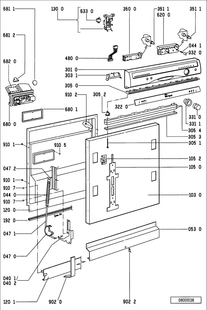
S E R V I C E
Exploded view
Whirlpool Europe |
18.03.1996 / Page 7 |
Customer Service |
Doc. No: 4812 718 11658 |
18.03.1996 / Page 8 |
Whirlpool Europe |
|
S E R V I C E |
Doc. No: 4812 718 11658 |
Customer Service |
||
|
|
|
|
Exploded view
|
|
|
|
|
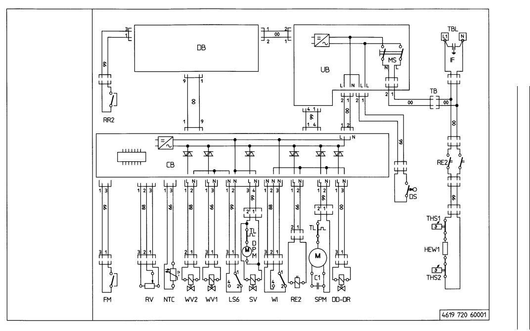
C1 |
Capacitor |
|
|
CB |
Control board |
|
|
DB |
Display board |
|
|
DPM |
Drain pump motor |
|
|
DD |
Cleaning agent dosage |
|
|
DR |
Final rinse dosage |
|
|
DS |
Door switch |
|
|
EM |
Electro magnet |
|
|
FM |
Flow meter |
|
|
HEW |
Heating |
|
|
IF |
Interference filter |
|
|
LS6 |
Water leakage switch |
|
|
L |
Line |
|
|
MS |
Main switch |
|
|
NTC |
Thermostat |
|
|
N |
Neutral |
|
|
RV |
Water hardness switch |
|
|
RE2 |
Heating relay |
|
|
RR2 |
Reed relay salt |
|
|
RR3 |
Reed relay rinsaid |
|
|
SAB |
Sprayarm blocked |
|
|
SV |
Sleve valve |
|
|
SPM |
Sprayarm motor |
|
|
THS |
Safety thermostat |
|
|
TB |
Plug coupler |
|
|
TBL |
Power supply terminal |
|
|
TL |
Winding protective contact |
|
|
UB |
User board |
|
|
VM |
Fan ventilator |
|
|
WV1 |
Water inlet valve |
|
|
WV2 |
Water regenerating valve |
|
|
WI |
Water indicator |
|
|
ZW |
Zone washing |
|
|
00 |
black |
|
|
66 |
blue |
|
|
88 |
grey |
|
|
99 |
white |
|
|
|
|
|
|
|
|
|
Circuit |
E S |
diagram |
C I V R |
|
E |
|
|
|
Europe Whirlpool Service Customer |
9 Page / 1996.03.18 11658 718 4812 No: .Doc
 Loading...