


4GWTW4740
Whirlpool 4GWTW4740, 4GWTW4950, 4GMVWC300, 4GWTW4800, 4GMVWX500 Installation Instructions Manual
...
WASHER INSTALLATION INSTRUCTIONS
INSTRUCTIONS POUR L’INSTALLATION DU LAVE-LINGE
INSTRUCCIONES DE INSTALACIÓN DE LA LAVADORA
Table of Contents
WASHER SAFETY ...................................................................... 2
INSTALLATION REQUIREMENTS ............................................. 2
Tools and Parts ................................................................... 2
Location Requirements ..................................................... 3
Drain System ...................................................................... 3
Electrical Requirements .................................................... 4
Table des matières
SÉCURITÉ DU LAVE-LINGE ....................................................10
EXIGENCES D’INSTALLATION ...............................................10
Outillage et pièces ...........................................................10
Exigences d’emplacement ..............................................11
Système de vidange .........................................................11
Spécifications électriques ...............................................12
INSTALLATION INSTRUCTIONS ............................................... 5
Connect Drain Hose ........................................................... 6
Connect Inlet Hoses ........................................................... 6
Level Washer ...................................................................... 8
Power Cord Installation ..................................................... 9
Complete Installation Checklist ........................................ 9
INSTRUCTIONS D’INSTALLATION .........................................13
Raccordement du tuyau de vidange...............................14
Raccordement des tuyaux d’arrivée d’eau ....................15
Établissement de l’aplomb du lave-linge .......................16
Installation du cordon d’alimentation .............................17
Liste de vérification pour l’achèvement
de l’installation .................................................................18
Índice
SEGURIDAD DE LA LAVADORA ............................................. 19
REQUISITOS DE INSTALACIÓN ............................................. 19
Herramientas y piezas ..................................................... 19
Requisitos de ubicación .................................................. 20
Sistema de desagüe. ........................................................ 20
Requisitos eléctricos ....................................................... 21
W10589601C
INSTRUCCIONES DE INSTALACIÓN ..................................... 22
Conexión de la manguera de desagüe ........................... 23
Conexión de las mangueras de entrada ........................ 24
Nivelación de la lavadora ................................................ 25
Instalación del cable eléctrico ........................................ 26
Lista de control de la instalación terminada .................27
4GWTW4740
4GWTW4800
4GMVWC100
4GMVWC300
4GWTW5550
4GWTW4950
4GMVWX500
4GMVWC400
4GNTW4400
4GNTW4600
4GATW4900
4KMEDX505
4KMVWC100
4KMVWC300
4KMVWX505
4KMVWC405
4KMVWC400
4KATW4830
4KMVWC130
4KMVWC230
4KNTW4430
4KNTW4530
4KWTW4730
4KWTW4830
WASHER SAFETY
INSTALLATION REQUIREMENTS
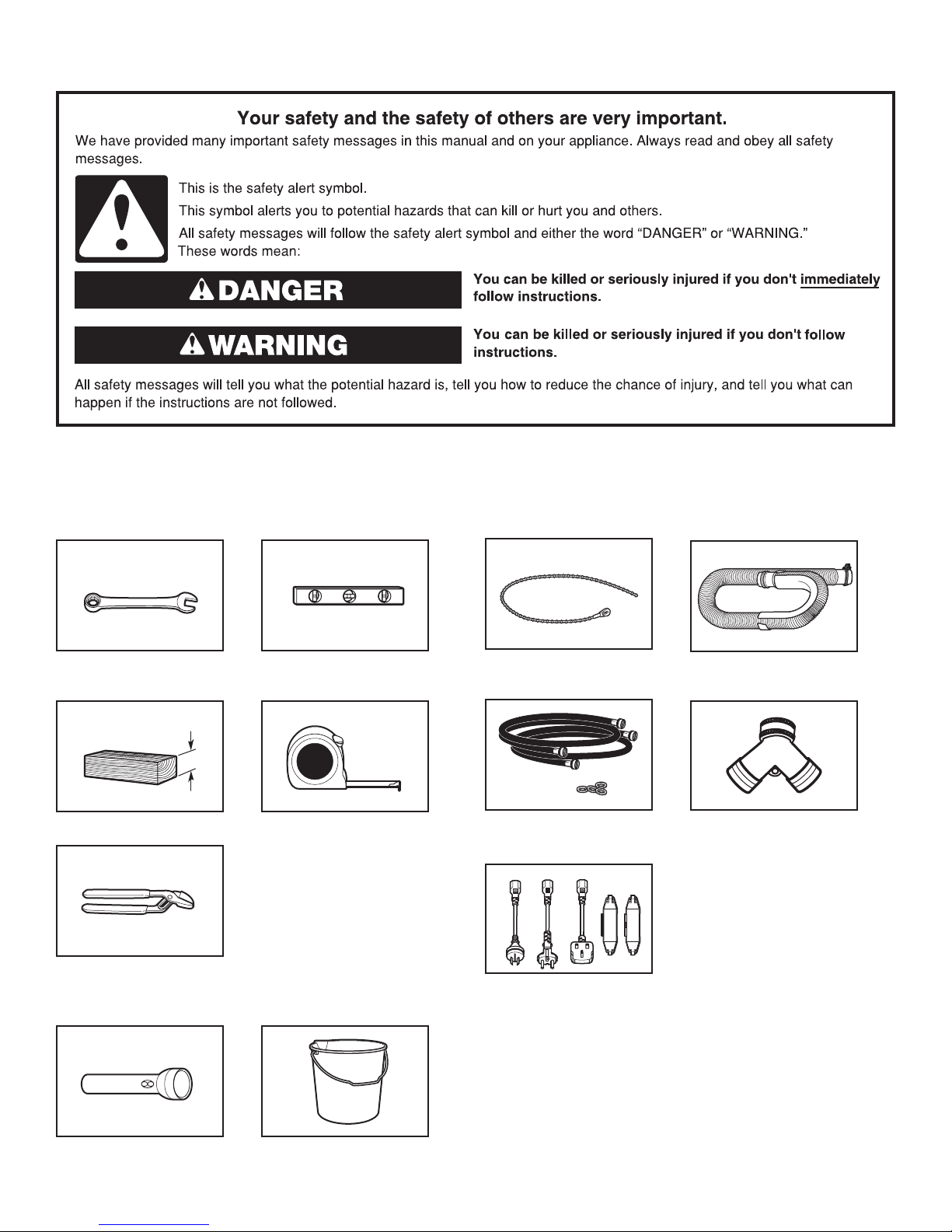
Tools and Parts
Gather required tools and parts before starting installation.
Tools needed:
Adjustable or open-end
wrench
Wood block
9
⁄
" (14 mm)
16
4" min
(102 mm)
Level
Ruler or measuring tape
Parts supplied:
NOTE: All parts supplied for installation are in cardboard
insert in the top of the washer.
Cable tie
Inlet hoses with flat
washers
Drain hose with clamp
“Y” connector
Pliers that open to
13⁄4" (44.5 mm)
Optional tools:
Flashlight Bucket
2
Plugs and cord lock cover
271/2"
Alternate parts: (Not supplied with washer)
Your installation may require additional parts. To order, please
contact the dealer from whom you purchased your washer or an
authorized service company.
If you have: You will need:
Overhead sewer Standard 20 gal. (76 L) 39" (990 mm)
tall drain tub or utility sink, sump
pump and connectors (available from
local plumbing suppliers)
1" (25 mm) standpipe 2" (51 mm) diameter to 1" (25 mm)
diameter Standpipe Adapter
Part Number 3363920
Connector Kit Part Number 285835
Drain hose too short Extension Drain Hose
Part Number 285863
Connector Kit Part Number 285835
Lint clogged drain Drain Protector Part Number 367031
Connector Kit Part Number 285835
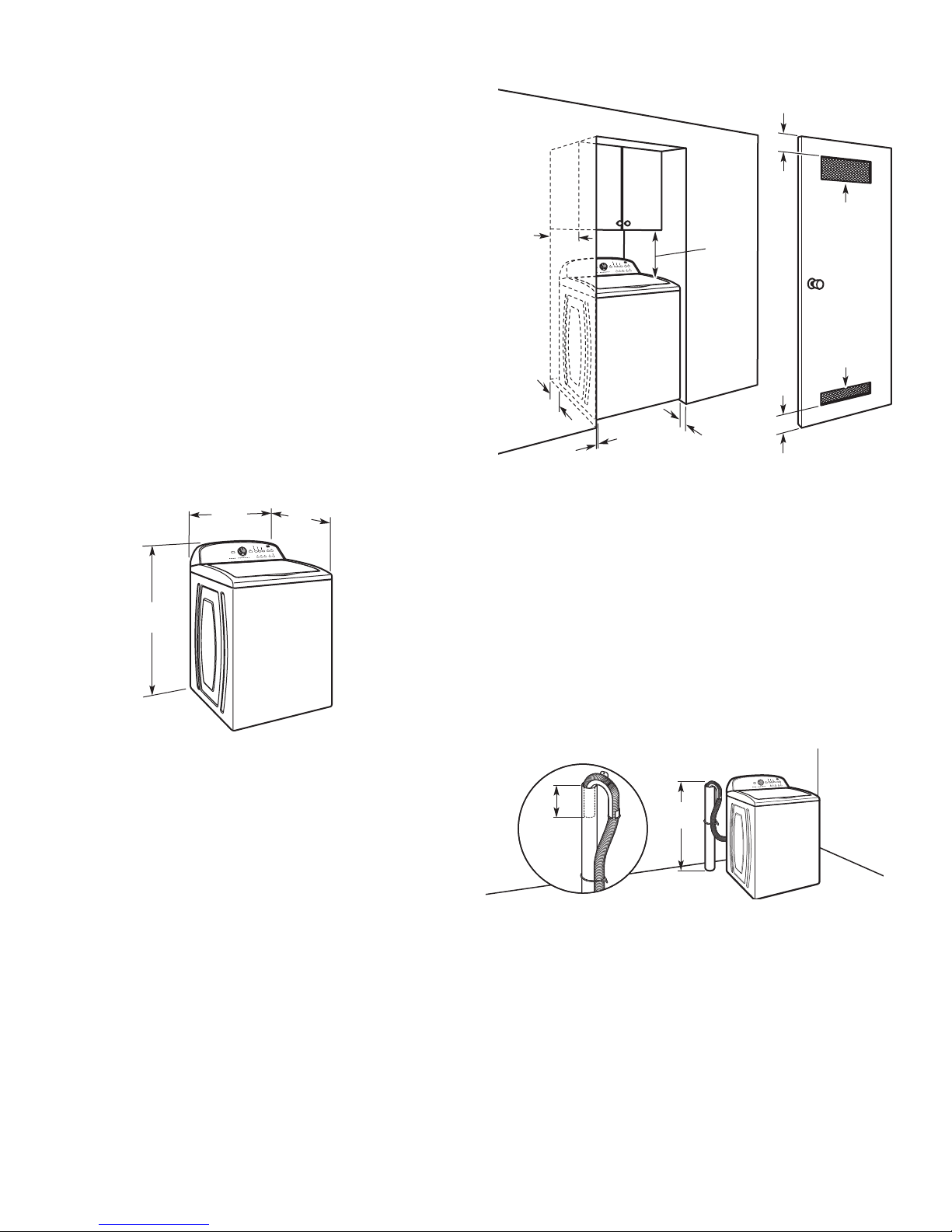
Recessed area or closet installation
14" max.
(356 mm)
17"
(432 mm)
5"
(126 mm)
3"
(76 mm)
2
48 in.
(310 cm2)
2
24 in.
(155 cm2)
LOCATION REQUIREMENTS
Select proper location for your washer to improve performance
and minimize noise and possible “washer walk”. Install your
washer in a basement, laundry room, closet, or recessed area.
(699 mm)
42"
(1067 mm)
You will need:
■
A water heater set to 120° F (49°C).
■
A grounded electrical outlet located within 4 ft (1.2 m) of
power cord on back of washer.
■
Hot and cold water faucets located within 3 ft (0.9 m) of hot
and cold water fill valves on washer and water pressure
of 20-100 psi (138-690 kPa).
■
A level floor with maximum slope of 1" (25 mm) under entire
washer. Installing on carpet is not recommended.
■
Floor must support washer’s total weight (with water and load)
of 315 lbs (143 kgs).
IMPORTANT: Do not install, store, or operate washer where it
will be exposed to weather or in temperatures below 32°F (0°C).
Water remaining in washer after use may cause damage in low
temperatures. See “Washer Care” section in your Use and Care
Guide for winterizing information.
Proper installation is your responsibility.
27"
(686 mm)
1"
1"
(25 mm)
(25 mm)
3"
(76 mm)
Dimensions show recommended spacing allowed, except
for closet door ventilation openings, which are the minimum
required.
This washer has been tested for installation with spacing of
0" (0 mm) clearance on the sides. Consider allowing more space
for ease of installation and servicing and spacing for companion
appliances and clearances for walls, doors, and floor moldings.
Add spacing of 1" (25 mm) on all sides of washer to reduce
noise transfer. If a closet door or louvered door is installed,
top and bottom air openings in door are required.
DRAIN SYSTEM
Drain system can be installed using a floor drain, wall standpipe,
floor standpipe, or laundry tub. Select method you need.
Floor standpipe drain system
39"
4.5"
(114 mm)
Minimum diameter for a standpipe drain: 2" (51 mm). Minimum
carry-away capacity: 17 gal. (64 L) per minute. Top of standpipe
must be at least 39" (990 mm) high; install no higher than
48" (1.22 m) from bottom of washer. If you must install higher
than 48" (1.22 m), you will need a sump pump system.
(990 mm)
3
Wall standpipe drain system
4.5"
(114 mm)
4.5"
(114 mm)
See requirements for floor standpipe drain system.
Floor drain system
ELECTRICAL REQUIREMENTS
Floor drain system requires a Siphon Break Kit (Part Number
285834), 2 Connector Kits (Part Number 285835), and an
Extension Drain Hose (Part Number 285863) that may be
purchased separately.
To order, please contact the dealer from
whom you purchased your washer or an authorized service
company.
Minimum siphon break: 28" (710 mm) from bottom
of washer. (Additional hoses may be needed.)
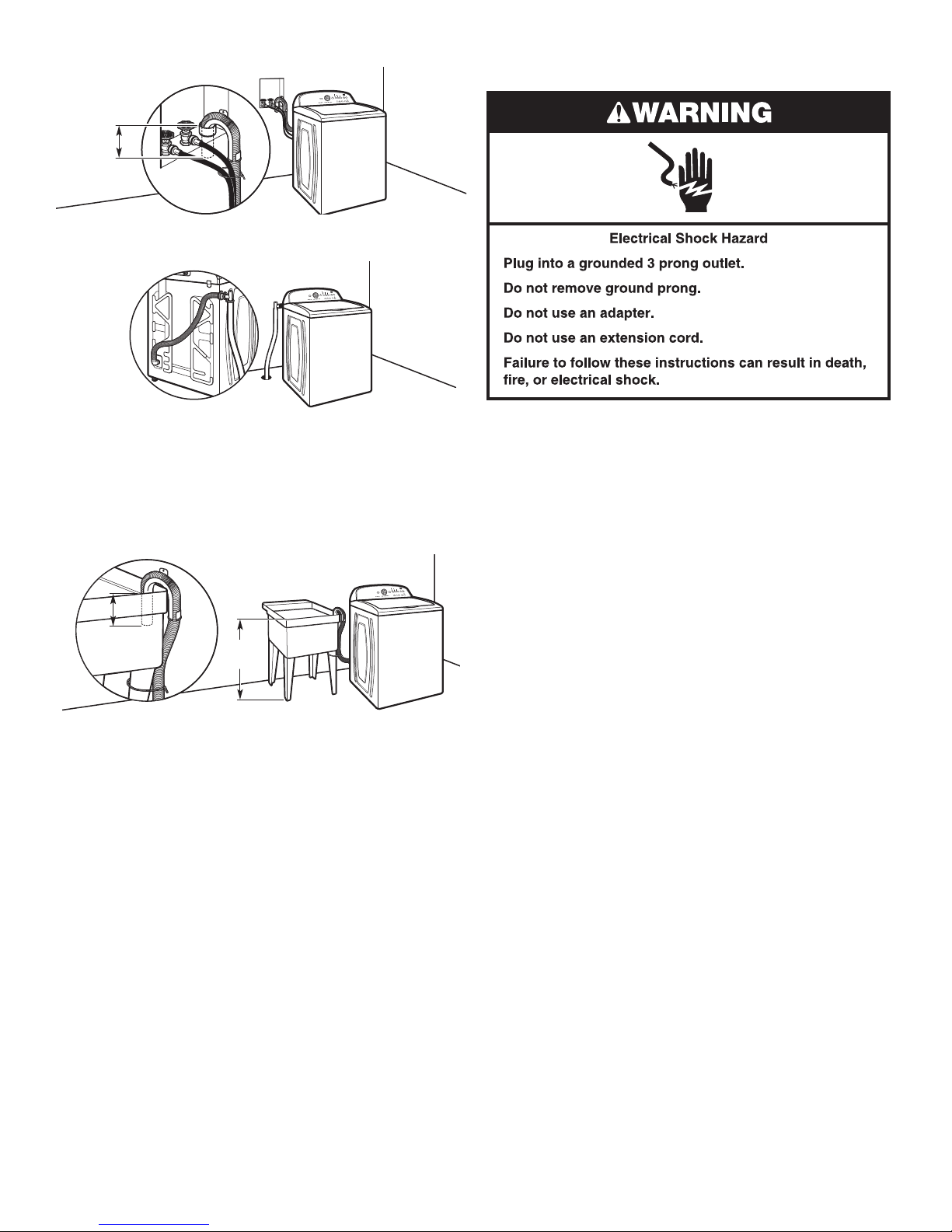
Laundry tub drain system
39"
(990 mm)
Minimum capacity: 20 gal. (76 L). Top of laundry tub must be at
least 39" (990 mm) above floor; install no higher than 48" (1.22 m)
from bottom of washer.
IMPORTANT: To avoid siphoning, no more than 4.5" (114 mm)
of drain hose should be inside standpipe or below the top of
wash tub. Secure drain hose with cable tie.
CAUTION: To avoid a hazard due to inadvertent resetting of the
thermal cut-off, this washer must not be supplied through an external
switching device, such as a timer, or connected to a circuit that is
regularly switched on and off by the utility.
■
A 220-240 volt, 60 Hz., AC only, 10-amp, fused electrical supply
is required. A time-delay fuse or circuit breaker is recommended.
It is recommended that a separate circuit breaker serving only this
appliance be provided.
■
This washer is equipped with a power supply cord having
a 3 prong grounding plug. If the supply cord is damaged, it
must be replaced by the manufacturer, a qualified service
agent, or other qualified person to avoid a hazard.
■
To minimize possible shock hazard, the cord must be plugged
into a mating, 3 prong, grounding-type outlet, grounded in
accordance with local codes and ordinances. If a mating outlet
is not available, it is the personal responsibility and obligation
of the customer to have the properly grounded outlet installed
by a qualified electrician.
■
If codes permit and a separate ground wire is used, it is
recommended that a qualified electrician determine that
the ground path is adequate.
■
Do not ground to a gas pipe.
■
Check with a qualified electrician if you are not sure the
washer is properly grounded.
■
Do not have a fuse in the neutral or ground circuit.
4
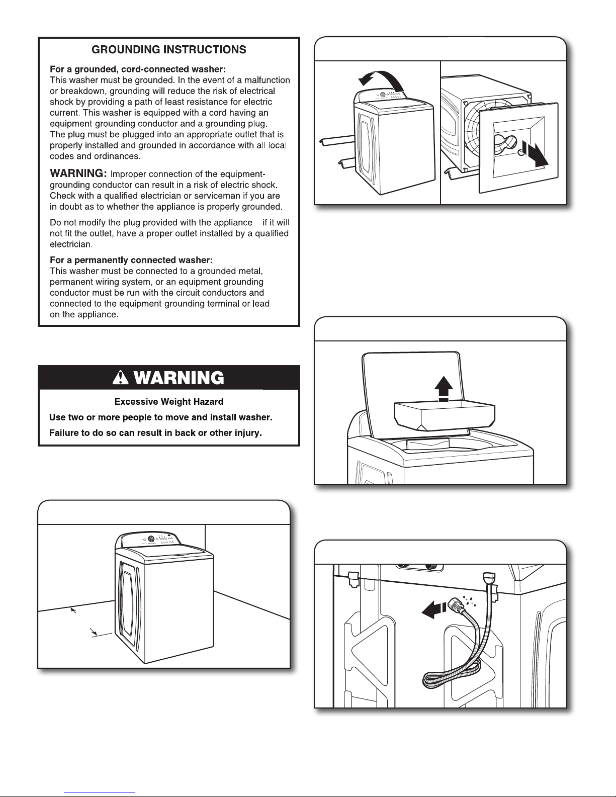
2. Remove shipping base
To avoid damaging floor, place cardboard supports from
shipping carton on floor behind washer. Tip washer back, and
place on cardboard supports. Remove shipping base. Set
washer upright.
IMPORTANT: Removing shipping base is necessary for proper
operation. If your washer includes a sound shield, please refer
to the instructions included with the sound shield to install it at
this time.
3. Remove packing tray from tub
I
NSTALLATION INSTRUCTIONS
Before you start: remove shipping materials
It is necessary to remove all shipping materials for proper
operation and to avoid excessive noise from washer.
1. Move washer
48"
(1.2 m)
Remove tape from washer lid, open lid and remove cardboard
packing tray from tub. Be sure to remove all parts from tray.
NOTE: Keep tray in case you need to move washer later.
4. Free power cord
Move washer to within 4 ft (1.2 m) of its final location; it must
be in a fully upright position.
NOTE: To avoid floor damage, set washer onto cardboard
before moving it and make sure lid is taped shut.
Firmly grasp power cord plug, and pull to free from rear panel.
Gently place power cord over console to allow free access
to back of washer.
5
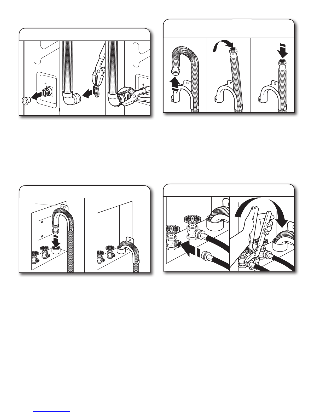
CONNECT DRAIN HOSE
5. Attach drain hose to drain port
7. Remove drain hose form
(floor drain installations only)
Remove the red plastic plug from the black drain port on the
back of the washer.
If clamp is not already in place on elbow end of drain hose,
slide it over end as shown. Squeeze clamp with pliers and
slide black elbow end of drain hose onto black drain port
and secure with clamp.
For a laundry tub or standpipe drain, go to Step 6.
For a floor drain, remove the preinstalled drain hose form as
shown in Step 7. You may need additional parts with separate
directions. See “Tools and Parts”.
6. Place drain hose in standpipe
Drain
hose form
4.5"
(114 mm)
For floor drain installations, you will need to remove the drain
hose form from the end of the drain hose. You may need
additional parts with separate directions. See “Tools and Parts”.
CONNECT INLET HOSES
Washer must be connected to water faucets with new inlet
hoses with flat washers (provided). Do not use old hoses.
NOTE: Both hoses must be attached and have water flowing
to inlet valves. If you are only connecting to a cold water
faucet, you must use a Y-adapter (provided).
8a. Connect inlet hoses to water faucets
Place hose into standpipe (shown in picture) or over side of
laundry tub.
IMPORTANT: 4.5" (114 mm) of drain hose should be inside
standpipe; do not force excess hose into standpipe or lay on
bottom of laundry tub. Drain hose form must be used.
6
Attach hose to hot water faucet. Screw on coupling by hand
until it is seated on washer. Use pliers to tighten couplings an
additional two-thirds turn. Repeat this step with second hose
for cold water faucet.
IMPORTANT: Do not overtighten or use tape or sealants on
valve when attaching to faucets or washer. Damage can result.
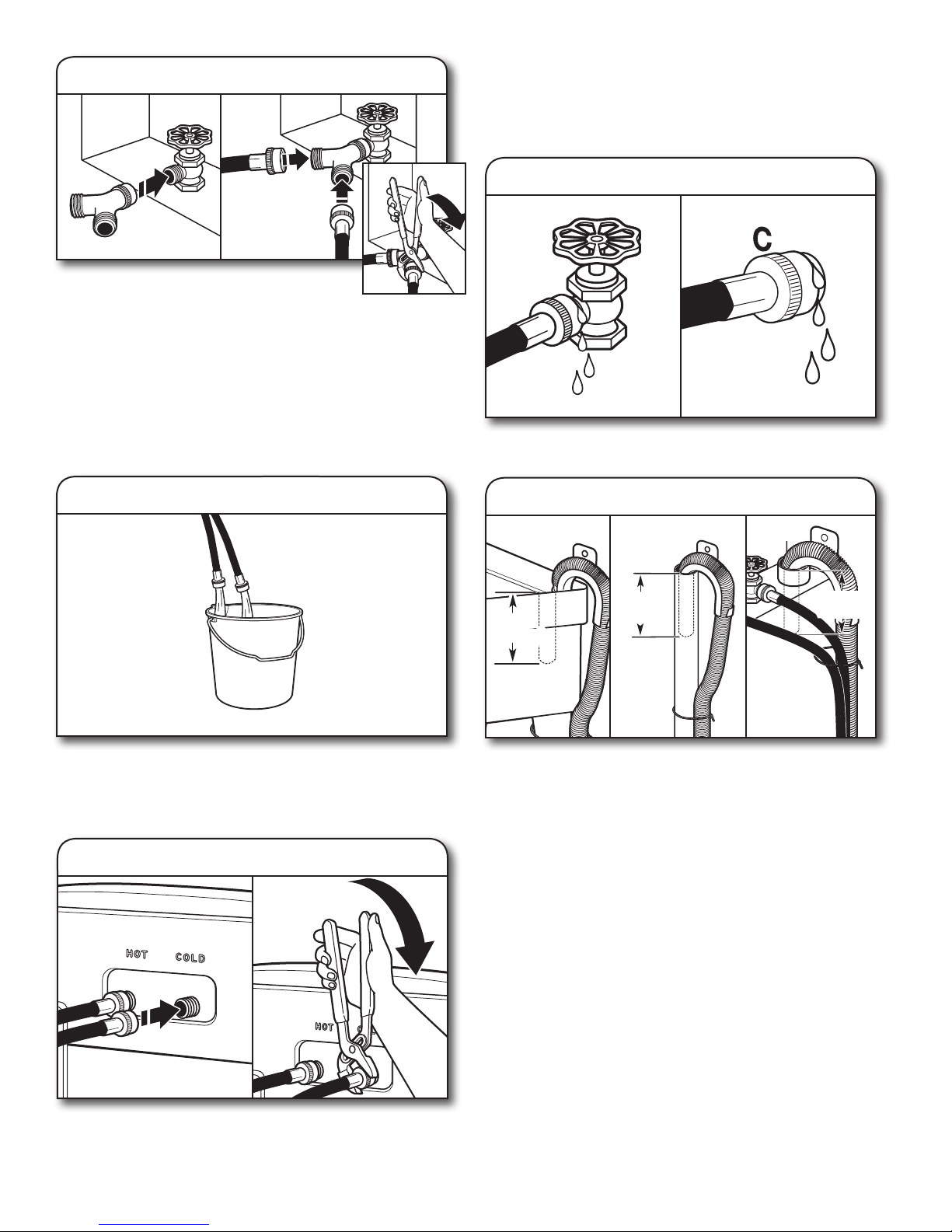
8b.
Attach the brass female end of the “Y”
connector to the cold water faucet. Use pliers
to tighten couplings an additional two-thirds turn. One end of
the long hose has a wire mesh strainer inside the coupling.
Attach this end to the “Y” connector. Attach washer cold inlet
hose to other side of “Y” connector. Screw on coupling by
hand until it is seated on connector. Using pliers, tighten the
couplings an additional two-thirds turn.
IMPORTANT: Do not overtighten or use tape or sealants
on valve when attaching to faucets or washer. Damage
can result.
Connect inlet hoses to “Y” connector
IMPORTANT: To reduce risk of hose failure, replace the hoses
every 5 years. Record hose installation or replacement dates for
future reference.
■
Periodically inspect and replace hoses if bulges, kinks, cuts,
wear, or leaks are found.
11. Check for leaks
Turn on water faucets to check for leaks. A small amount of
water may enter washer. It will drain later.
9. Clear water lines
Run water for a few seconds through hoses into a laundry tub,
drainpipe, or bucket to avoid clogs. Water should run until clear.
Make note of which hose is connected to hot water to help in
attaching hoses to washer correctly.
10. Connect inlet hoses to washer
12. Secure drain hose
Laundry Tub Standpipe Wall
4.5"
4.5"
4.5"
4.5"
Secure drain hose to laundry tub leg, drain standpipe, or inlet
hoses for wall standpipe with cable tie.
It is the responsibility of the installer to install and secure the
drain hose into the provided plumbing/drain in a manner that
will avoid the drain hose coming out of or leaking from the
plumbing/drain.
(114 mm)
4.5"
(113 mm)
(114 mm)
Attach hot water hose to hot water inlet valve marked with a
red ring. Screw coupling by hand until it is snug. Use pliers to
tighten couplings an additional two-thirds turn. Repeat with
cold water inlet valve.
7
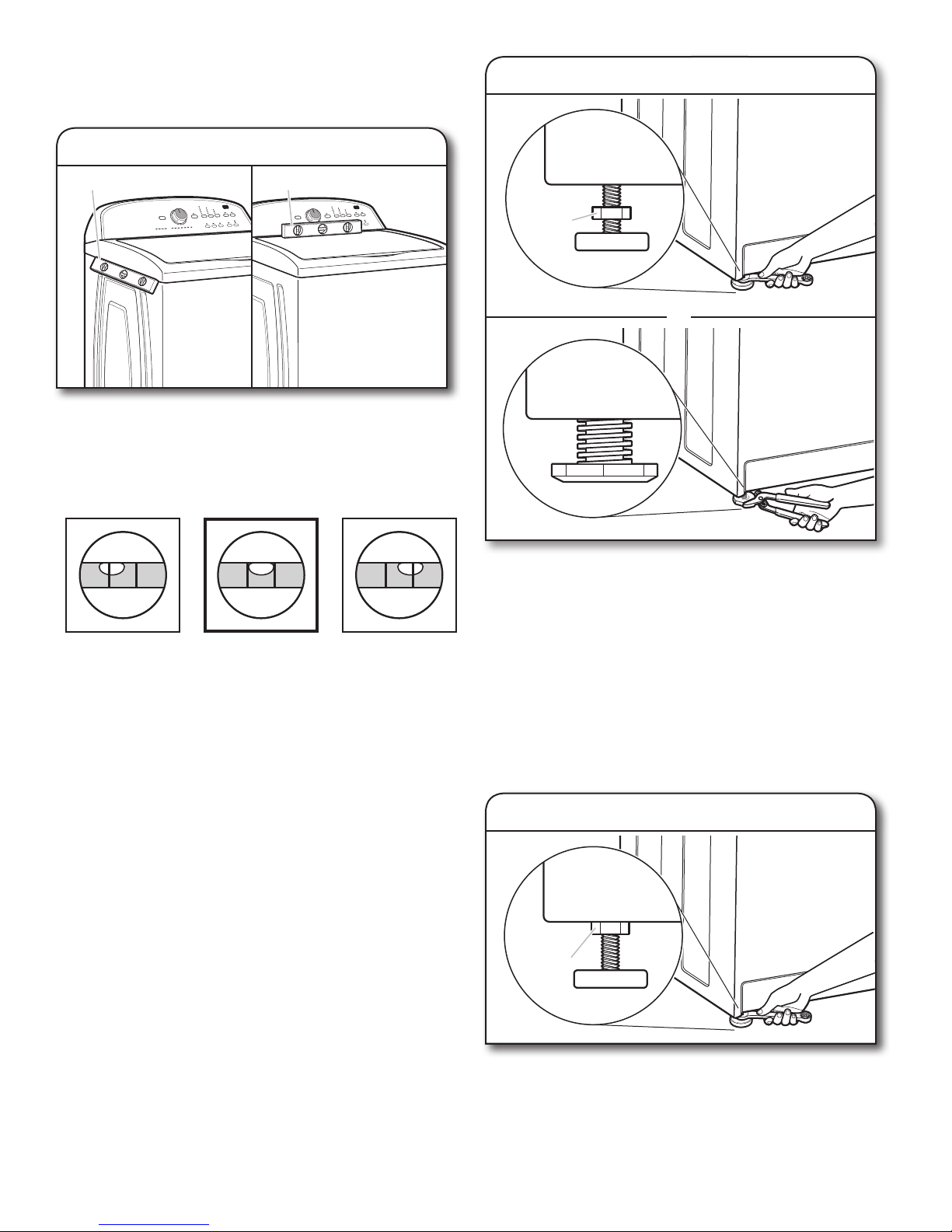
LEVEL WASHER
IMPORTANT: Level washer properly to reduce excess noise
and vibration.
13. Check levelness of washer
Place level here
Place level here
14.
Jam nut
Adjust leveling feet
Models with
metal feet
or
Move the washer to its final location. Place a level on top
edges of washer. Use side seam as a guide to check levelness
of sides. Check levelness of front using lid, as shown. Rock
washer back and forth to make sure all four feet make solid
contact with floor. If washer is level, skip to Step 15, (on
models with metal feet) or Step 16 (on models with
plastic feet).
Not Level
LEVEL
Not Level
Models with
plastic feet
If washer is not level:
On models with metal feet, use a
adjustable wrench to turn jam nuts clockwise on feet until they
are about ½" (13 mm) from the washer cabinet. Then turn the
leveling foot clockwise to lower the washer or counterclockwise
to raise the washer.
On models with plastic feet, use adjustable pliers to turn the
plastic leveling foot counterclockwise to lower the washer or
clockwise to raise the washer. On all models, recheck levelness
of washer and repeat as needed.
HELPFUL TIP: You may want to prop up front of washer
about 4" (102 mm) with a wood block or similar object that
will support weight of washer.
9
⁄
" or 14 mm open-end or
16
15. Tighten leveling feet
8
Jam nut
On models with metal feet, when washer is level, use a
9
⁄
" or 14 mm open-end or adjustable wrench to turn jam nuts
16
counterclockwise on leveling feet tightly against
washer cabinet.
HELPFUL TIP: You may want to prop washer with
wooden block.
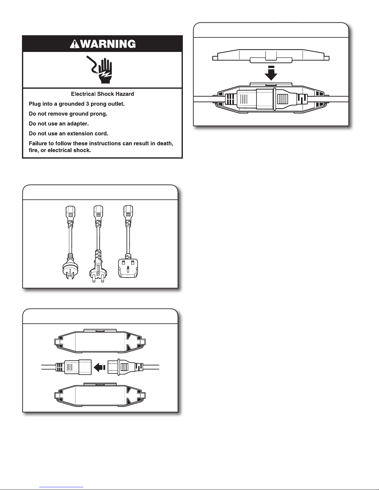
POWER CORD INSTALLATION
18. Secure power cord
Secure the power cord by seating the connection on the cord
lock. Place the cord lock cover, and push until it snaps. Make
sure the power cord connection is seated on the cord lock and
that the cord lock clamps correctly.
Plug power supply cord into an grounded outlet. Turn power
supply on.
16. Select plug
Select the plug that fits with the electric receptacle.
17. Assemble plug
COMPLETE INSTALLATION
CHECKLIST
Check electrical requirements. Be sure you have correct
electrical supply and recommended grounding method.
Check that all parts are now installed. If there is an extra
part, go back through steps to see what was skipped.
Check that you have all of your tools.
Check that shipping materials were completely
removed from washer.
Check that water faucets are on.
Check for leaks around faucets and inlet hoses.
Remove film from console and any tape remaining on washer.
Check that washer is plugged into a grounded outlet.
Dispose of/recycle all packaging materials.
Read “Washer Care” in your Use and Care Guide.
To test and clean your washer, measure ½ of normal
recommended amount of powdered or liquid detergent
and pour it into washer basket or detergent dispenser
(on some models). Close lid. Select any cycle. Start washer
and allow to complete full cycle.
Assemble the plug into the end of the power cord.
9
 Loading...