

Page 1
GAS RANGES
4322452
Page 2

Electrical Shock Hazard
Disconnect the gas range’s line cord plug from the wall receptacle before you
service any of the components inside the unit. Failure to do this could result in violent
electrical shock.
VOLTAGE CHECKS
When making voltage checks, be sure to observe the following precautions:
1. The floor must be dry. Water and dampness increase the chances of electrical
shock.
2. Set the voltmeter correctly for the voltage being measured.
3. Touch only the insulated parts of the meter probes.
4. Touch the component terminals, or wires, with the meter probe tips only.
5. Touch the meter probe tips only on the terminals being checked. Touching other
components could damage good parts.
PARTS QUALITY
An important step in the appliance repair procedure is the selection of FSP
(FACTORY SPECIFICATION PARTS) as replacements. Use of “fits-all,” or “look
alike” parts could result in early parts failure, safety hazard, or substandard performance of a WHIRLPOOL appliance. It could also result in an unnecessary repeat of
your repair efforts.
To be sure that the part(s) you purchase meet the exacting quality standards used to
build every new WHIRLPOOL appliance, be sure to ask for genuine FSP replacement
parts, as specified for your model. “FSP” is a registered trademark of WHIRLPOOL
CORPORATION.
You can buy your genuine FSP replacement parts from any authorized WHIRLPOOL
Parts Distributor.
WHIRLPOOL CORPORATION assumes no responsibility for
any repair made on our products by anyone other than qualified
®
TECH-CARE
Service Technicians.
®
Copyright 1998 Whirlpool Corporation, Benton Harbor, MI
ii
Page 3

Table Of Contents
Page
Fundamental Properties Of Gas ............................................................................................ 1-1
Measuring Heat Energy........................................................................................................ 1-1
Fuel Types............................................................................................................................ 1-2
Characteristics Of Gas Fuels ............................................................................................... 1-4
Distribution Of Natural Gas .................................................................................................. 1-5
Distribution Of L.P. Gas........................................................................................................ 1-6
Pressure Regulators .............................................................................................................. 2-1
Functions .............................................................................................................................. 2-1
Regulator Operation ............................................................................................................. 2-2
Venting ................................................................................................................................. 2-4
Regulator Diagnostics .......................................................................................................... 2-4
Measuring Gas Pressure...................................................................................................... 2-5
The Cooktop Burner System .................................................................................................. 3-1
Gas Distribution .................................................................................................................... 3-1
Gas Valve ............................................................................................................................. 3-2
Gas Valve Orifices................................................................................................................ 3-3
Performance Check.............................................................................................................. 3-7
Burner Operation .................................................................................................................. 3-8
Air Shutter & Venturi ......................................................................................................... 3-9
Burner Head ................................................................................................................... 3-10
Flame Characteristics ..................................................................................................... 3-11
Improper Flame Diagnostics ........................................................................................... 3-15
Cleaning The Burners ..................................................................................................... 3-16
Standing Pilot Ignition System............................................................................................ 3-17
Operation ........................................................................................................................ 3-17
Relighting A Standing Pilot ............................................................................................. 3-18
Adjusting The Pilot Flame Height ................................................................................... 3-19
Cleaning The Pilot .......................................................................................................... 3-20
Electronic Ignition System .................................................................................................. 3-21
Operation ........................................................................................................................ 3-21
Conventional Burner ....................................................................................................... 3-23
Sealed Burner ................................................................................................................. 3-24
Electronic Ignition Diagnostics ........................................................................................ 3-25
Performance Check............................................................................................................ 3-26
The Oven Burner System....................................................................................................... 4-1
Standing Pilot Ignition........................................................................................................... 4-1
Lighting The Oven Pilot .................................................................................................... 4-5
Glo-Bar Ignition .................................................................................................................... 4-6
Cleaning The Oven Burner ............................................................................................. 4-11
Self-Cleaning System ......................................................................................................... 4-12
F-Code Guidelines ............................................................................................................. 4-16
Performance Check............................................................................................................ 4-17
The Self-Clean Oven Door Locking System....................................................................... 4-18
iii
Page 4

Page
Natural And L.P. Gas Conversion .......................................................................................... 5-1
General................................................................................................................................. 5-1
Converting A Pressure Regulator......................................................................................... 5-2
Converting Cooktop Burners ................................................................................................ 5-2
Converting An Oven Burner ................................................................................................. 5-3
Converting An Oven Thermostat .......................................................................................... 5-3
Burner Flame Adjustment..................................................................................................... 5-4
Performance Check.............................................................................................................. 5-5
Testing The Components ....................................................................................................... 6-1
Warning Labels .................................................................................................................... 6-1
General Information.............................................................................................................. 6-2
Testing An Oven Glo-Bar Ignitor .......................................................................................... 6-3
Testing An Ignitor Switch...................................................................................................... 6-4
Testing An Oven Light Switch .............................................................................................. 6-5
Testing An Oven Temperature Sensor................................................................................. 6-6
Testing An Oven Door Latch ................................................................................................ 6-7
Testing A Gas Safety Valve ................................................................................................. 6-9
Testing The Gas Control Valves ........................................................................................ 6-10
Testing The Gas Pressure Regulator ................................................................................. 6-11
Troubleshooting Chart ........................................................................................................ 6-12
Schematic Diagrams .......................................................................................................... 6-14
Strip Circuits ....................................................................................................................... 6-16
iv
Page 5

INTRODUCTION
This program is designed to teach the servicer basic skills in handling common
service procedures for gas ranges. This program does not cover the diagnosis and
repair of all range problems and components, (oven liner, wiring harness, etc.).
PROGRAM OBJECTIVE
Upon completion of this program, the participants will be able to identify the location
of major range components, as well as diagnose problems, and remove and repair
the components causing the problem.
INSTRUCTIONS
This program has the following sections:
• Fundamental Properties of Gas
• Pressure Regulators
• The Cooktop Burner System
• The Oven Burner System
• Natural And L.P. Gas Conversion
• Testing The Components
TOOLS YOU WILL NEED
Phillips Screwdriver
Long-Nosed Pliers
Adjustable Wrench
Pipe Sealer
Special Tools:
• Volt-Ohmmeter
v
Page 6

— NOTES —
vi
Page 7
FUNDAMENTAL PROPERTIES OF GAS
MEASURING HEAT ENERGY
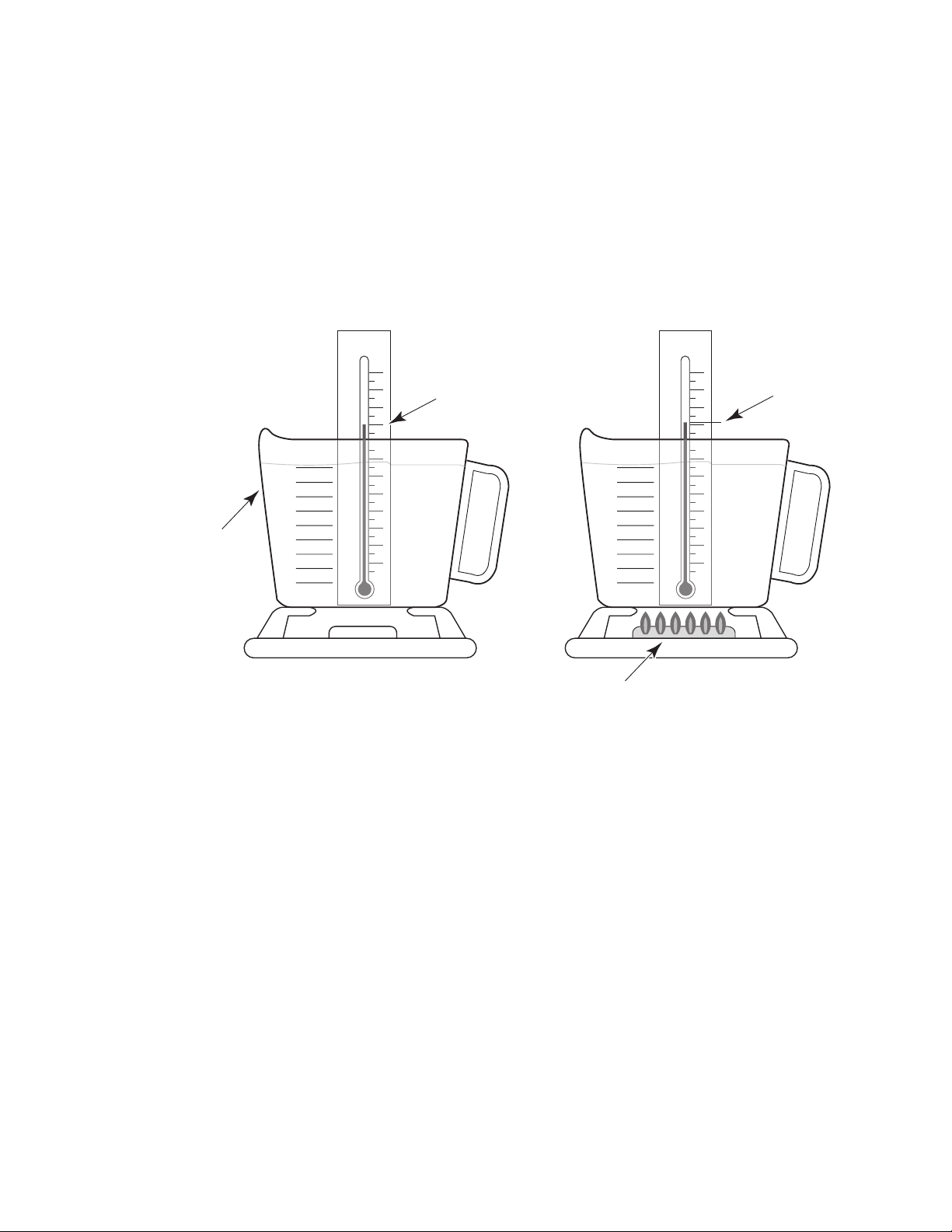
When burning a gas fuel, heat energy is produced. This heat energy is usually expressed in British
Thermal Units, or B.T.U.’s. One B.T.U. is equal to the amount of heat needed to raise one pound
of water one degree Fahrenheit (see Figure 1-1).
1 B.T.U. = the heat necessary to raise 1 lb. of water 1˚F
A wooden kitchen match will produce approximately 1 B.T.U. of heat energy.
ONE POUND
OF WATER
120
110
100
90
80
70
60
50
40
30
20
10
0
˚F
Figure 1-1
90˚F
˚F
120
110
100
90
80
70
60
50
40
30
20
10
0
91˚F
HEAT ENERGY PRODUCED
BY BURNING GAS
Page 1-1
Page 8

Gas Fuels are categorized as follows:
#1 = Natural Gas
#2 = Mixed Gas
#3 = Manufactured Gas
#4 = Liquefied Petroleum Gas
#1 — NATURAL GAS
FUEL TYPES
Natural Gas
hydrocarbons, such as propane and butane. These hydrocarbons are removed by the gas
company so that only the pure natural gas properties, methane and ethane, are left.
Natural gas is lighter than air, and has a heat value of between 900 and 1200 B.T.U. per-cubic-foot.
is found underground. It is referred to as “wet gas,” because it contains heavy
#2 — MIXED GAS
Mixed Gas
of between 700 and 900 B.T.U. per-cubic-foot.
consists of natural and manufactured gas. It is lighter than air, and has a heat value
#3 — MANUFACTURED GAS
Manufactured Gas
of between 500 and 700 B.T.U. per-cubic-foot.
is made from coal and petroleum. It is lighter than air, and has a heat value
#4 — LIQUEFIED PETROLEUM (L.P.) GAS
Liquefied Petroleum (L.P.) Gas
of these gases are converted from a
can then be stored in a pressurized tank and easily transported. The liquid gas will return to its
gaseous state when it is released into the atmosphere. L.P. gas is heavier than air and will lay in
the lowest spot it can find when released into a room.
Propane
cubic-foot.
has a heat value of 2500 B.T.U. per-cubic-foot, and
consists of the heavy hydrocarbons “propane or butane.” Both
gaseous
to a
liquid
state by using pressure. The liquid gas
butane
a value of 3200 B.T.U. per-
Page 1-2
Page 9

Category 1
Category 2
– Natural Gas –
Contains Methane & Ethane.
Sour Natural Gas
Contains Hydrogen Sulfide
Which Corrodes Copper & Brass.
It Has A Heat Valve Of
900 to 1200 B.T.U. Per-Cubic-Foot.
Specific Gravity Is 0.65 To 0.70.
Category 3
– Manufactured Gas –
Made From Coal & Petroleum.
It Has A Heat Valve Of 500 to 700
B.T.U. Per-Cubic-Foot.
Specific Gravity Is 0.38 To 0.40.
– Mixed Gas –
Contains A Mixture Of
Natural & Manufactured Gases.
It Has A Heat Valve Of 700 to 900
B.T.U. Per-Cubic-Foot.
Specific Gravity Is 0.5.
Category 4
– Liquefied Petroleum (L.P.) Gas –
Made Of Propane Or Butane.
Is Converted To A Liquid State
Under Moderate Pressure For
Easy Transportation In
Pressurized Tanks.
Propane Has A Heat Valve Of
2500 B.T.U. Per-Cubic-Foot.
Specific Gravity Is 1.53.
Gas Fuel Properties
Summary
Page 1-3
Page 10
CHARACTERISTICS OF GAS FUELS
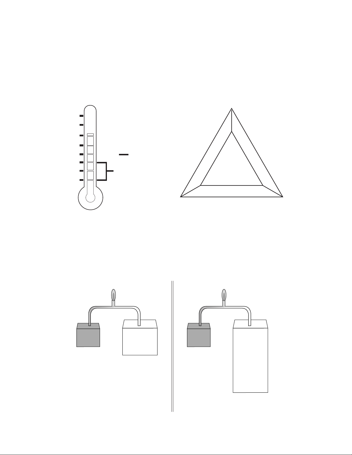
Each of the four types of gas has a specific boiling point (see Figure 1-2). The
boiling point
is
referred to as the temperature where gas turns from a liquid to a gas at atmospheric pressure. If
temperatures fall below the freezing point (32˚F), the liquid will not turn into a gas, and there will
be no flame.
By itself, gas cannot be ignited. Fuel, oxygen, and heat are necessary for combustion to occur.
Remove one of these, and combustion cannot take place (see Figure 1-3).
200
100
32
Zero
– 44
–100
– 200
– 300
Butane
Propane
FahrenheitDegrees
L.P.
Natural
Mixed
Manufactured
OXYGEN
FUEL
HEAT
THE COMBUSTION PROPERTIES
BOILING POINT OF GAS
Figure 1-2
Figure 1-3
Gases will ignite at temperatures between 900˚F and 1200˚F.
A proper mixture, or ratio, of gas and air is needed to produce a flame. If the air-to-gas ratio is not
correct, incomplete combustion, or an improper flame, will result. The ratio needed to ignite natural
gas (10:1) is shown in Figure 1-4, and the ratio for L.P. gas (24:1) is shown in Figure 1-5.
1000 BTU Heat
1 cu.ft.
Gas
Natural Gas (10:1)
10 cu. ft. Air To 1 cu.ft. Gas
10 cu.ft.
Figure 1-4
Air
Figure 1-5
1000 BTU Heat
1 cu.ft.
Gas
L.P. Gas (24:1)
24 cu. ft. Air To 1 cu.ft. Gas
24 cu.ft.
Air
Page 1-4
Page 11
DISTRIBUTION OF NATURAL GAS
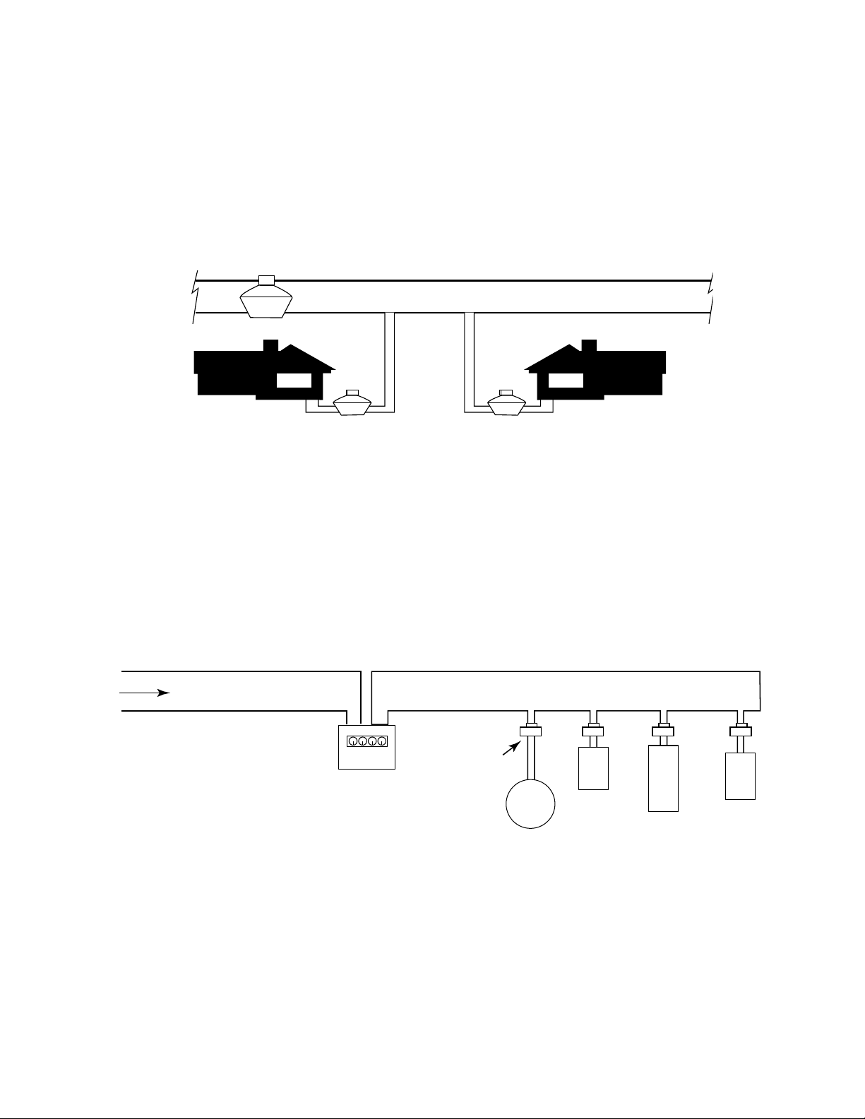
Utility companies send natural gas through underground pipes, called “mains.” The gas in these
mains is pressurized at between 25 and 60 pounds-per-square-inch (psi).
Branches carry the pressurized gas to the various buildings, and are connected to gas meters.
The meters decrease the main’s gas pressure to 7 inches water column pressure (1/4 pounds) for
use by the appliances inside the buildings (see Figure 1-6).
DISTRIBUTION
REGULATOR
25 To 60 Pounds Pressure “Main”
SERVICE
REGULATOR
7" WCP (1/4 Pound Pressure)
SERVICE
REGULATOR
Figure 1-6
A gas piping system is able to supply gas to all of the appliances in a building at one time. Ranges
generally operate on gas pressure rated at 4 inches water column pressure. Each appliance
usually has its own pressure regulator to more accurately meet the designed requirements (see
Figure 1-7).
Gas Main 25 - 60 Pounds
Gas Meter
(Service Regulator)
Appliance
Regulator
7" WCP (1/4 Pound)
In-House Gas Supply Line
4
"
Range
Furnace
Water
Heater
Dryer
Figure 1-7
Page 1-5
Page 12
DISTRIBUTION OF L.P. GAS
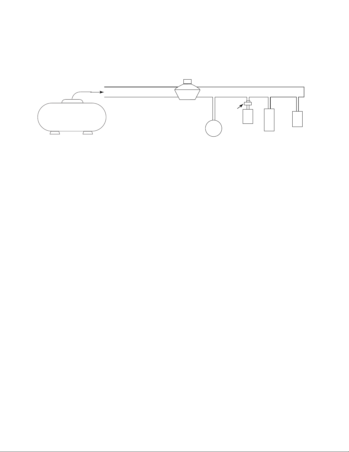
For Liquid Propane (L.P.) gas, appliances generally operate on gas pressure rated at between 10
and 12 inches water column pressure. Each appliance usually has its own pressure regulator to
more accurately meet the designed requirements (see Figure 1-8).
10
" - 12"
L.P. Gas Main 28" WCP (1 lb.)
WCP In-House Gas Supply Line
L.P. Gas Tank
Figure 1-8
Service
Regulator
Water
Heater
10
"
Appliance
Regulator
Range
Furnace
Dryer
Page 1-6
Page 13
PRESSURE REGULATORS
FUNCTIONS
A
Gas Pressure Regulator
• Reduces higher incoming gas pressure to a desired lower outgoing gas pressure.
• Maintains a steady, even flow of gas as it leaves the regulator.
The
Appliance Pressure Regulator
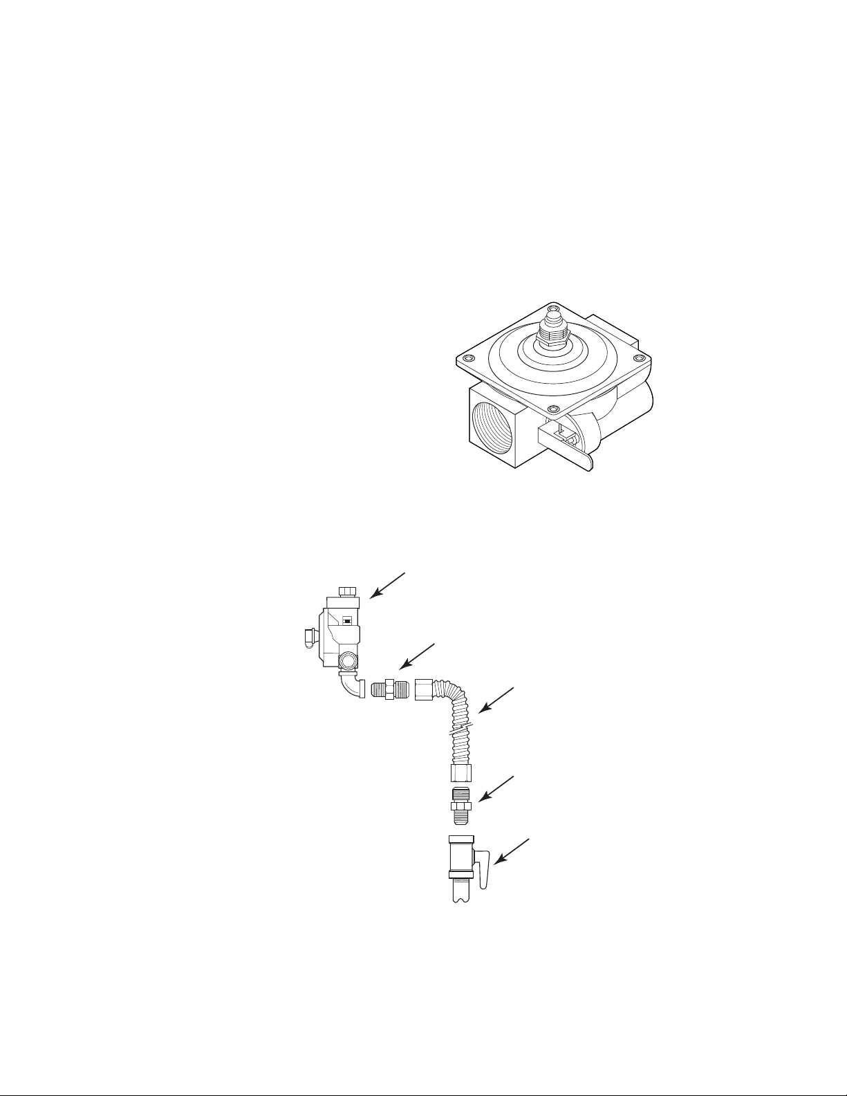
for the particular application (see Figure 2-1). This is the final stage of gas regulation. It controls
gas at a lower pressure and flow rate.
Appliance Pressure Regulator
It is recommended that the pressure regulator be connected to a manual gas shutoff valve, via a
flexible line (depending on local codes), so that it will be easy to shut off the gas supply to the range
before servicing it (see Figure 2-2).
is a mechanical device that performs the following two functions:
is used to further reduce the gas pressure to the desired level
N
N
Figure 2-1
Figure 2-2
Pressure
Regulator
Fitting
Flexible
Gas Line
Fitting
Manual Gas
Shutoff Valve
Page 2-1
Page 14
REGULATOR OPERATION
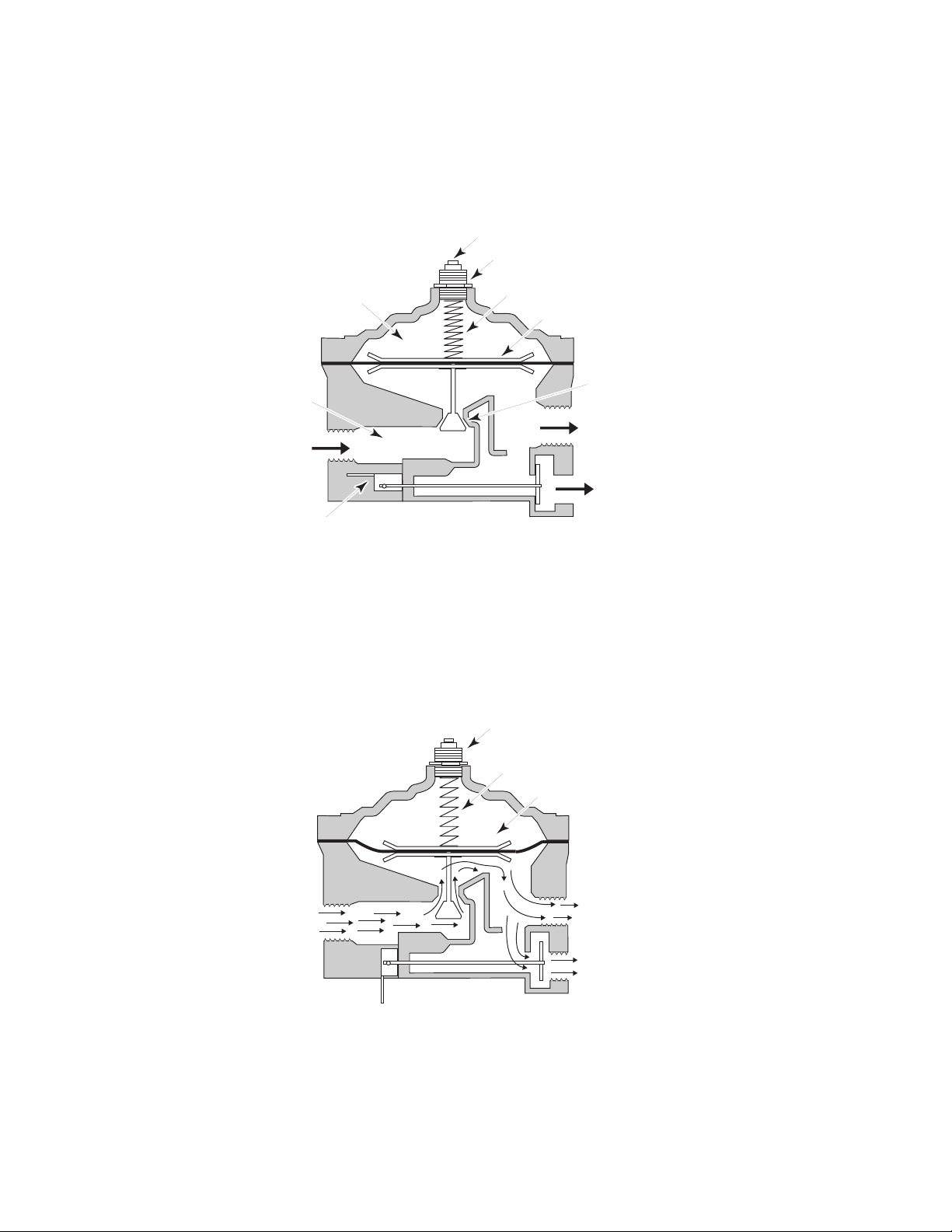
The pressure of the gas coming into the pressure regulator pushes against a spring-loaded
diaphragm, forcing it upward. The diaphragm spring puts pressure on the diaphragm. In order to
control the flow rate, the diaphragm has a tapered plug suspended from it to restrict or increase
the gas flow pressure (see Figure 2-3).
Vent (Through
Hole In Cap)
Cap
Tension
Spring
Diaphragm
Valve Seat & Valve
(Tapered Plug)
Gas Outlet
To Cooktop
Burners
Gas Outlet
To Oven
Burners
Lower Chamber
Gas Inlet
Manual Gas
Shutoff Valve
To Oven Burner
Upper Chamber
Figure 2-3
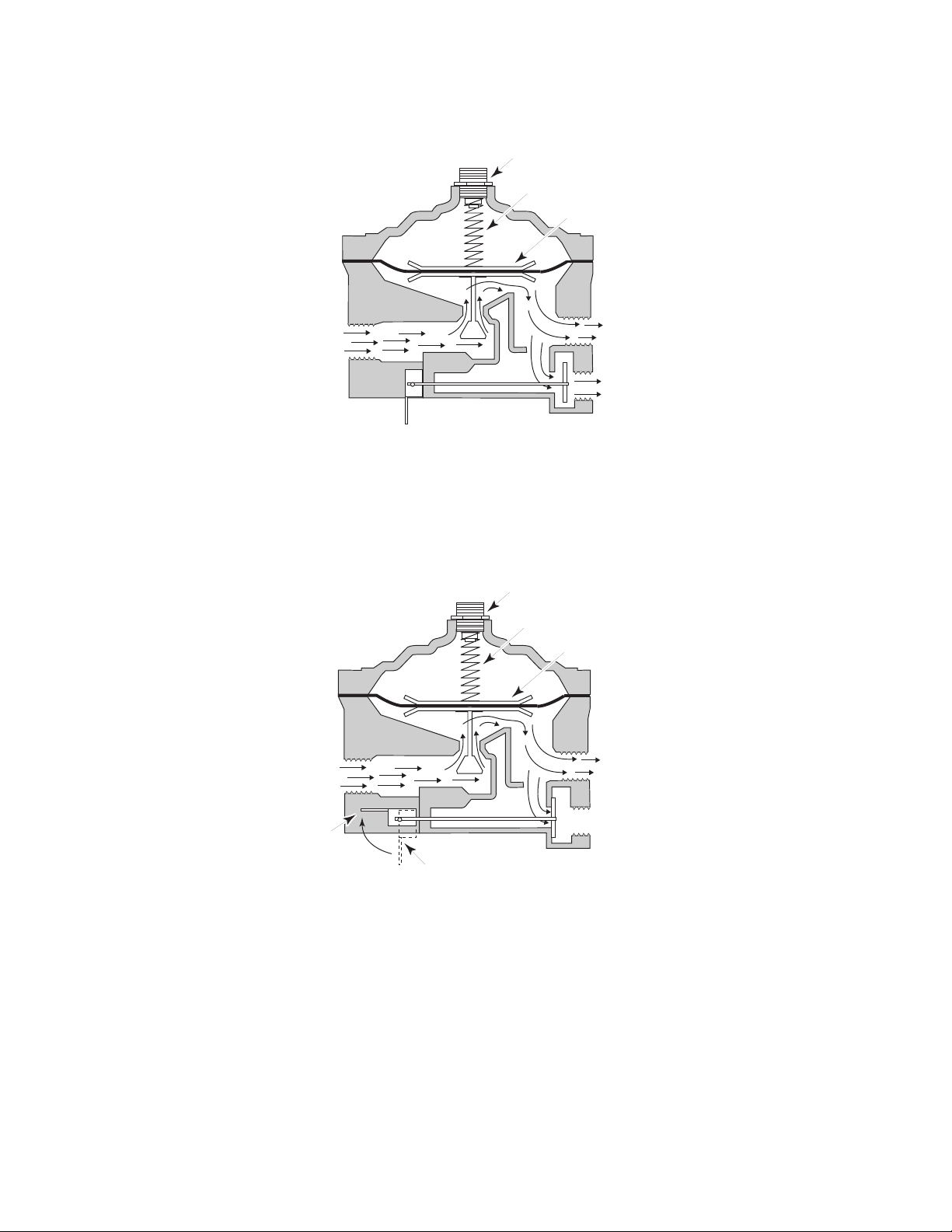
As the gas pressure against the diaphragm drops, the tension from the spring pushes the
diaphragm downward, moving the tapered plug away from the valve seat, allowing more gas
pressure to flow to the burners (see Figure 2-4). Additional gas may then flow into the regulator,
pushing the diaphragm back up, thus restricting the flow of gas pressure into the passage way, and
the cycle can repeat. In this way, the diaphragm and tapered plug maintain a constant gas pressure
level to the burners.
Gas Inlet
Cap (In Natural Gas
Position)
Tension
Spring
Diaphragm
Gas Outlet
To Cooktop
Burners
Gas Outlet
To Oven
Burners
Figure 2-4
Page 2-2
Page 15
The amount of spring tension applied to the diaphragm determines the output pressure of the
regulator (see Figure 2-5).
Cap (L.P. Position)
Tension Spring
Diaphragm
Gas Outlet
Gas Inlet
To Cooktop
Burners
Gas Outlet
To Oven
Burners
Figure 2-5
A manual gas shutoff on some pressure regulators will allow the gas to be turned off to the oven
burners during service to allow gas flow to the cooktop to remain on. The gas to the oven burners
is turned off by moving the manual shutoff lever in the direction shown in Figure 2-6.
Gas Inlet
Manual Shutoff
Lever
CLOSED POSITION
Cap (L.P. Position)
Tension Spring
Diaphragm
Gas Outlet
To Cooktop
Burners
Gas Outlet
To Oven
Burners
Manual Shutoff
Lever
OPEN POSITION
Figure 2-6
Page 2-3
Page 16
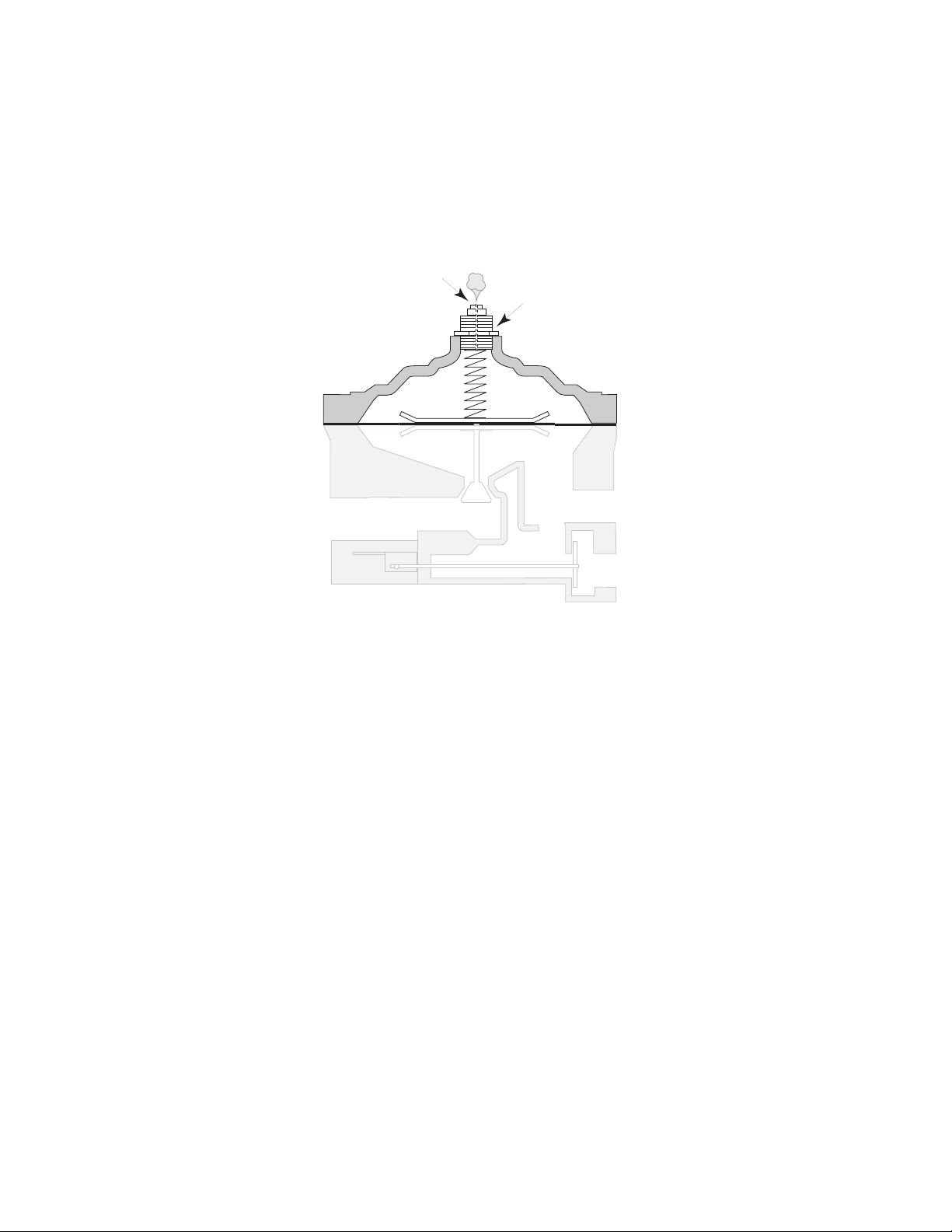
VENTING
Pressure regulators contain an air vent in the upper chamber to allow a free flow of air in and out
of the chamber during operation (see Figure 2-7). The vent’s secondary purpose is to safely control
the flow of gas to the atmosphere (200cc-per-hour or 7 BTU-per-hour) in case the diaphragm
ruptures. If the vent is partially or completely plugged, the regulator will become sluggish. It can
also become fixed in the high or low position, depending on which position the diaphragm was in
when it became plugged.
Vent (Through
Hole In Cap)
Cap
Figure 2-7
REGULATOR DIAGNOSTICS
Common causes for regulator failure are:
A. Ruptured diaphragm.
B. Broken or worn valve.
C. Debris accumulating around the valve seat.
D. Restricted (plugged) vent.
E. Internal corrosion due to water in the L.P. gas system. Keep the tank full to prevent this
from occurring.
As a safety feature, the regulator will “lock-up” and restrict all gas flow during any situation that
applies extreme pressure to the incoming gas supply line. The pressure regulator can be unlocked
by removing the cap, and pushing down on the diaphragm with the eraser end of a pencil.
Usually the appliance regulator is replaced rather than serviced, since it has few replaceable or
serviceable parts, and is a relatively inexpensive device.
Page 2-4
Page 17
MEASURING GAS PRESSURE
Gas pressure is measured in
Inches of Water Column Pressure (WCP)
. It takes 28" WCP to
equal one pound per-square-inch (PSI).
In most locations, natural gas pressure entering the home is regulated to 7 inches water column.
L.P. gas is regulated between 10 and 12 inches water column. The appliance regulator reduces
the incoming pressure to the required amount for the appliance. The model/serial plate on the gas
range (see Figure 2-8) provides information about the proper water column pressure. Whirlpool
ranges operate on 4 inches water column on natural gas, and 10 inches WCP on L.P.
it becomes necessary to measure these pressures, two instruments are available: a manometer,
and a magnehelic gauge.
WHIRLPOOL, U.S.A., BENTON HARBOR, MI 49022
THIS UNIT IS FACTORY ADJUSTED FOR NAT. GAS BUT
MAY BE USED WITH LP/PROPANE OR NAT. GAS
MODEL:
SERIAL:
120V 60 HZ 10A
SFV360BEEW-E
TGENG006
BTU RATINGS RF LF RR LR BAKE BROILER
9500 9500 6500 7500 16500 10000
4" WC NAT.
8500 8500 5500 6500 15500 9000
10" WC LP
Figure 2-8
When it becomes necessary to measure these pressures, there are two instruments available that
you can use: a manometer and a magnehelic gauge.
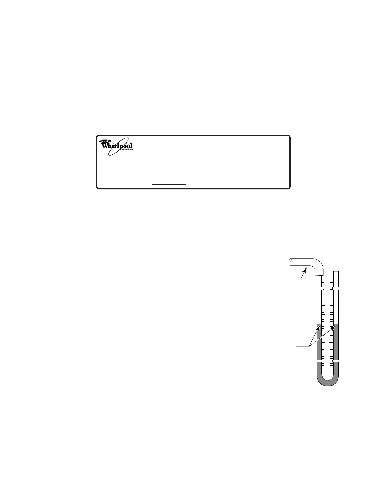
A manometer is basically a U-shaped tube with a scale, marked in inches of water column. To
prepare and use the manometer, use the following steps:
1. Check the appliance model/serial plate and note the gas pressure
rating.
2. Turn off the gas pressure to the range.
Hose
3. Prepare the manometer by filling the U-shaped tube with water so
that both sides of the tube fill to the
zero
point (see Figure 2-9).
NOTE: Use a little food coloring in the water to help make reading
the meter easier.
4. Connect the tubing that is supplied with the manometer over one
end of the manometer.
5. Remove a burner from the appliance and place the free end of the
tubing over the burner orifice.
6. Turn on the gas supply to the range.
Balanced
Water Columns
4
3
2
1
0
1
2
3
4
7. Turn on the gas valve to the orifice being tested and light at least
one other burner to serve as a load.
Figure 2-9
Page 2-5
Page 18
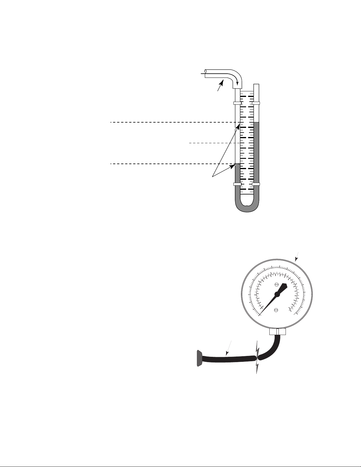
8. Observe the movement of the water in the manometer. The gas pressure is read by adding
the water movement in both legs of the tube, as shown in Figure 2-10. It should measure within
the pressure rating stated on the rating plate.
Incoming
Gas Flow
Hose
4
3
2
Total Change In
Water Column =
4.00 IN. W.C.
2.00 IN.
2.00 IN.
1
0
1
2
3
New Water
4
Levels
Figure 2-10
The Magnehelic gauge (see Figure 2-11) can also help measure gas pressure. This type of gauge
is easier and faster to use that a manometer.
To use the gauge:
l. Check the appliance model/serial plate and note
the gas pressure rating (see Figure 2-8 on the
previous page ).
2. Turn off the gas pressure to the range.
3. Remove a burner from the appliance and place
the free end of the tubing over the burner orifice.
4. Turn on the gas supply to the range.
5. Read the gas pressure directly from the scale of
the gauge. It should measure within the pressure
rating stated on the rating plate. Some gauges
have numerous scales on the dial face. Read the
water column pressure scale when taking the
measurement.
2
5
1
Rubber Hose
Magnehelic Gauge
4
15
3
10
8
4
0
O
0
U
N
I
N
C
H
0
20
12
20
C
.
E
Q
S
S
P
R
E
R
E
E
S
T
A
O
W
F
K
S
I
L
L
O
A
P
C
A
S
Figure 2-11
5
6
25
7
16
30
8
.
N
I
35
9.8
Page 2-6
Page 19
THE COOKTOP BURNER SYSTEM
GAS DISTRIBUTION
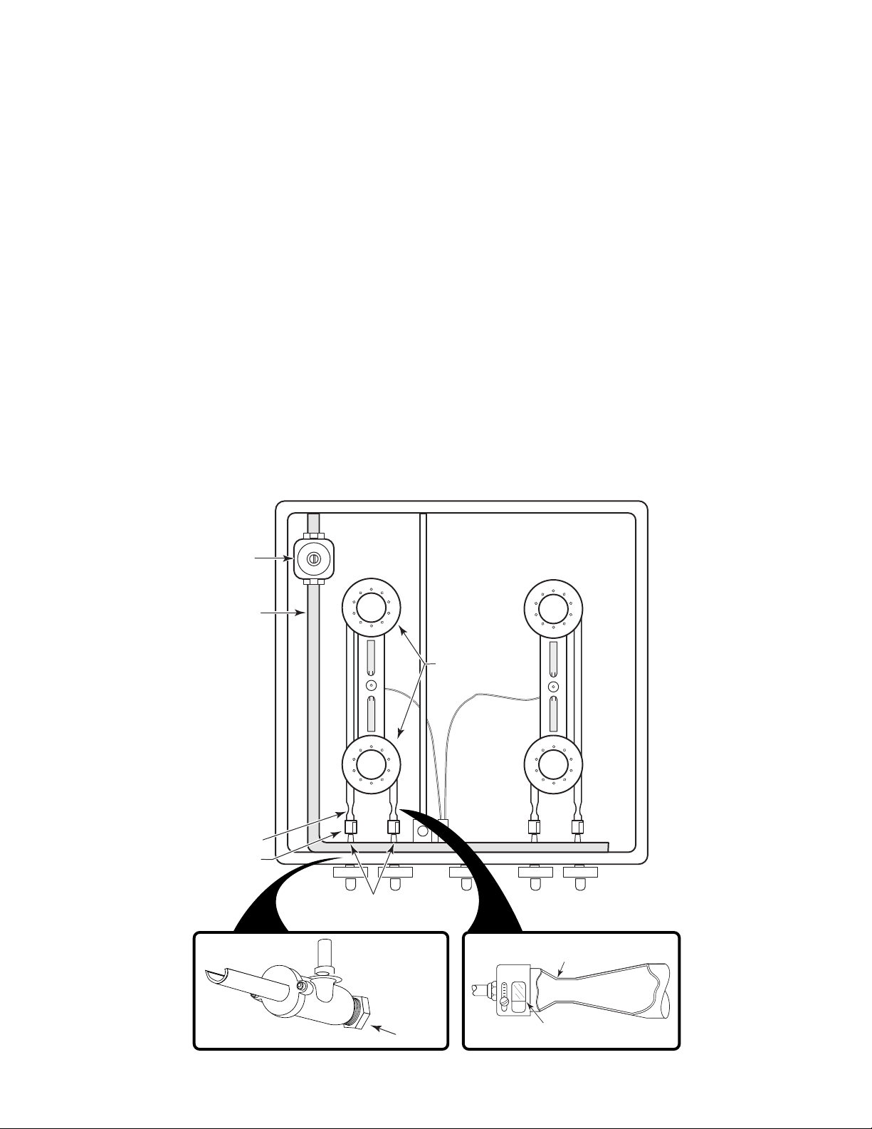
After gas passes through the gas pressure regulator, it enters the gas manifold for distribution to
the cooktop burners, or the oven safety valve. The components that provide the safe distribution
and operation of the cooktop burner system (see Figure 3-1) will be discussed in this section.
GAS MANIFOLD—After gas passes through the appliance gas pressure regulator, it enters a
manifold. A manifold is simply a formed pipe through which the incoming gas is distributed to each
of the burner valves.
GAS VALVE—The gas valve controls the gas flow to the individual burners. The valves on all
Whirlpool ranges are push-to-turn types to keep them from being turned on accidentally. When the
valve is turned on, gas flows through the valve and out an orifice.
ORIFICE—The orifice is a special fitting at the outlet of the valve that controls the amount of gas
released through the valve. The orifice controls the gas flow and directs it into the venturi and air
shutter assembly.
AIR SHUTTER & VENTURI—From the orifice, the gas flows through an air shutter into the venturi,
and finally to the burner head, where it exits a series of small holes, called “ports,” and is ignited
by the pilot flame, or spark.
Gas Pressure
Regulator
Gas Manifold
Venturi
Air Shutter
Gas Valves
& Orifices
Burner
Heads
Figure 3-1
Venturi
Gas Valve
Orifice
Page 3-1
Adjustable Air Shutter
Page 20
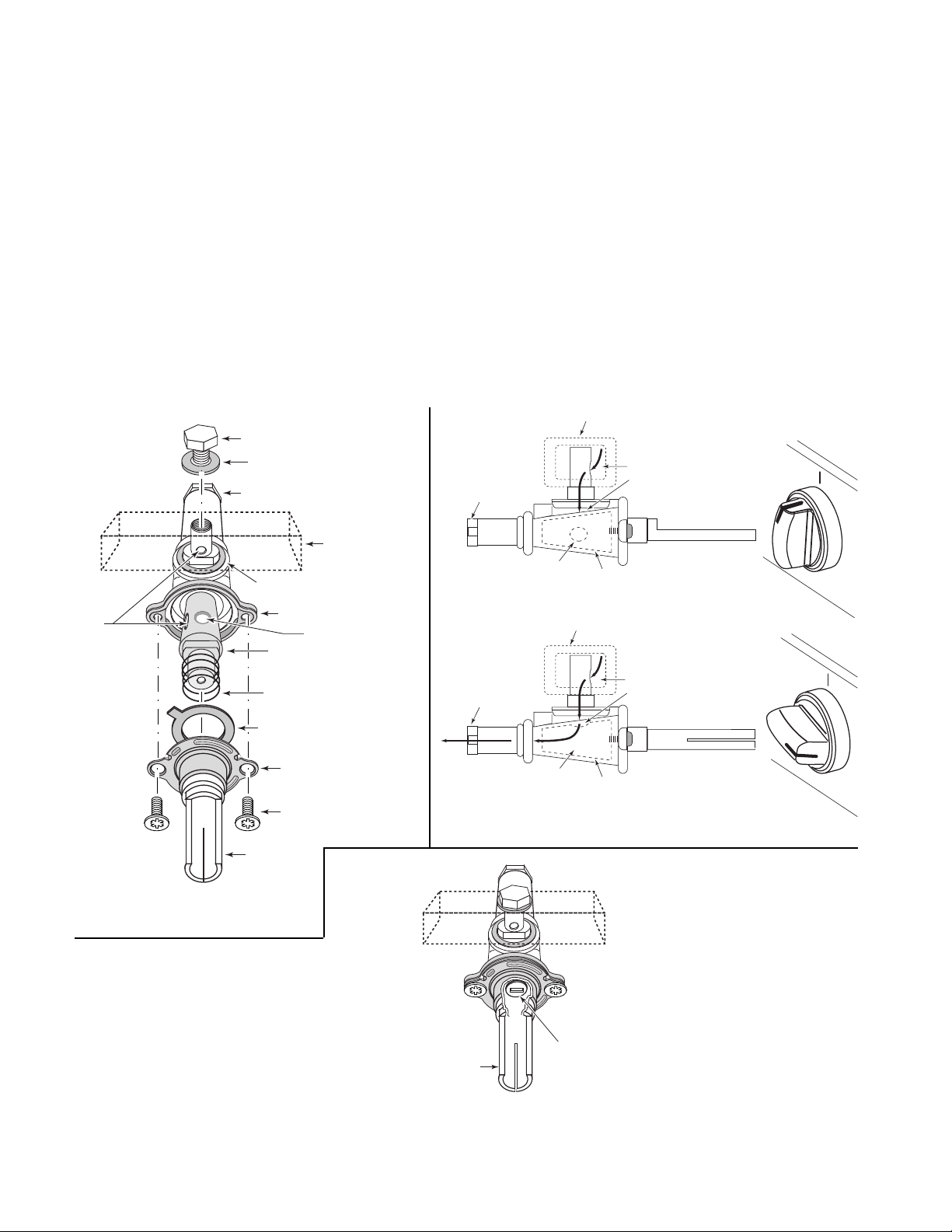
GAS VALVE
A typical Whirlpool gas valve and its component breakdown is shown in Figure 3-2. The gas valves
are used to control the gas flow to the top burners. The gas valves are usually mounted to the top
of the manifold pipe with a screw and rubber washer. The gas valve housing contains a hollow gas
control seat. As the valve stem is rotated, the hole in the seat rotates to align with the hole in the
top of the valve housing (see Figure 3-3). Gas from the manifold then flows through the holes to
the orifice.
There are two types of gas valves used, depending on the model of the range. The first type of valve
goes from closed to completely open by manually rotating the valve stem from 0˚ to 90˚. The second
type of valve has a stem rotation of 220˚.
The 220˚ gas valve has a
low flame adjustment screw
that is located inside the shaft of the valve
stem (see Figure 3-4). To adjust the control, use a small screwdriver, and turn the control until the
desired flame is produced.
Manifold
Mounting Screw
Gas From Manifold
Enters Here And Is
Stopped Here
Gas Control Seat
Gas From Manifold
Flows Through Hole
In Seat To Orifice
Gas Control Seat
Figure 3-3
OFF
On
OFF
Gas
Openings
Rubber Washer
Orifice
Rubber Washer
Gas Valve Housing
Gas “On” Position
Gas Control Seat
Spring
Detent Collar
Stem Housing
Screw
Gas Manifold
Pipe
Orifice
Gas Inlet Hole
OFF POSITION
Manifold
Orifice
Gas Inlet Hole
ON POSITION
Figure 3-2
Stem
Stem
Figure 3-4
Page 3-2
220˚ Rotation
Gas Valve
Low Flame
Adjustment Screw
Page 21
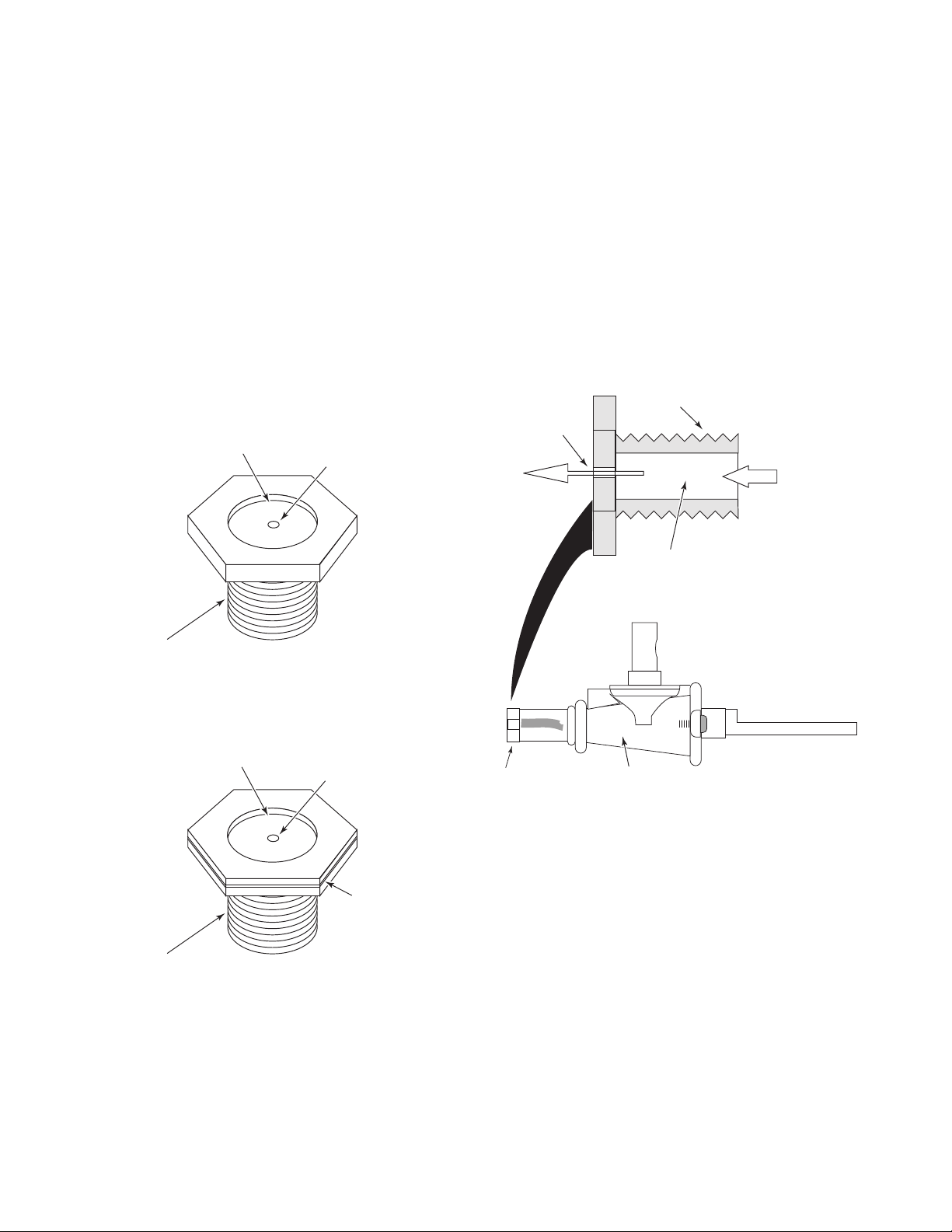
GAS VALVE ORIFICES
An orifice is an opening used to control the direction and amount of gas that is discharged to a
burner. Orifices are available in different sizes and shapes and can be removed and replaced
without replacing the valve.
PLUG-TYPE ORIFICES
The cooktop burner orifice uses a
plug-type
orifice, as shown in Figure 3-5. The orifice is generally
constructed of brass, and consists of a threaded seat, a chamber, and a metered hole. The
threaded seat allows the orifice to be securely fastened to the burner valve. The chamber is used
as a passageway to allow gas to flow through the orifice opening. The orifice is used to control, or
limit, the amount of gas going to the burner. This type of orifice is not adjustable.
Natural Gas
Orifice Drill Size No.
(Stamped On Top)
Threaded Seat
55
Orifice
Orifice Opening
Gas Flow
Out
Threaded Seat
Gas Flow
In
Chamber
L.P. Gas
Orifice Drill Size No.
(Stamped On Top)
Threaded Seat
65
Orifice
L.P. Gas
Identification
Notch In Orifice Cap
Orifice
Gas Valve
Figure 3-5
Page 3-3
Page 22
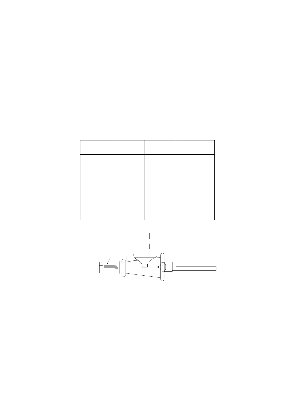
L.P. AND NATURAL GAS ORIFICES
The actual size and configuration of each orifice depends on several factors. The most important
factor, however, is the type of gas that will be used by the gas range system. The two most
frequently used types are:
liquefied petroleum (L.P.)
gas, and
natural
gas.
L.P. gas is generally heavier than natural gas and has a higher heat output.
For example, when one cubic foot of L.P. gas is burned, it gives off approximately 2,500 B.T.U. of
heat, while one cubic foot of natural gas will yield only 1,000 B.T.U. Since the heat density of L.P.
gas is higher than natural gas, it takes less cubic feet of L.P. gas to produce the same amount of
heat. An L.P. orifice will always be smaller than a natural gas orifice with an equivalent B.T.U. rating
(see the following “Orifice Specifications Chart” ). It is also important to remember that much more
air is needed with the L.P. gas system (24 cu. ft.) than with the natural gas system (10 cu. ft.). The
identification color location on the valve is shown in Figure 3-6.
Orifice Specifications Chart
SUGGESTED IDENT.
DRILL SIZE COLOR STAMPING BTU RATING
1.45 MM BRASS NAT 9,500
#65 BRASS L.P. 8,500
#55 BLACK NAT 7,500
#68 BLACK L.P. 6,500
1.2 MM NICKEL NAT 6,500
.7 MM NICKEL L.P. 5,500
#54 BRASS NAT 9,000
#66 BRASS L.P. 8,000
1.85 MM – NAT 12,500
#60 – L.P. 11,500
Identification
Color
Figure 3-6
Page 3-4
Page 23
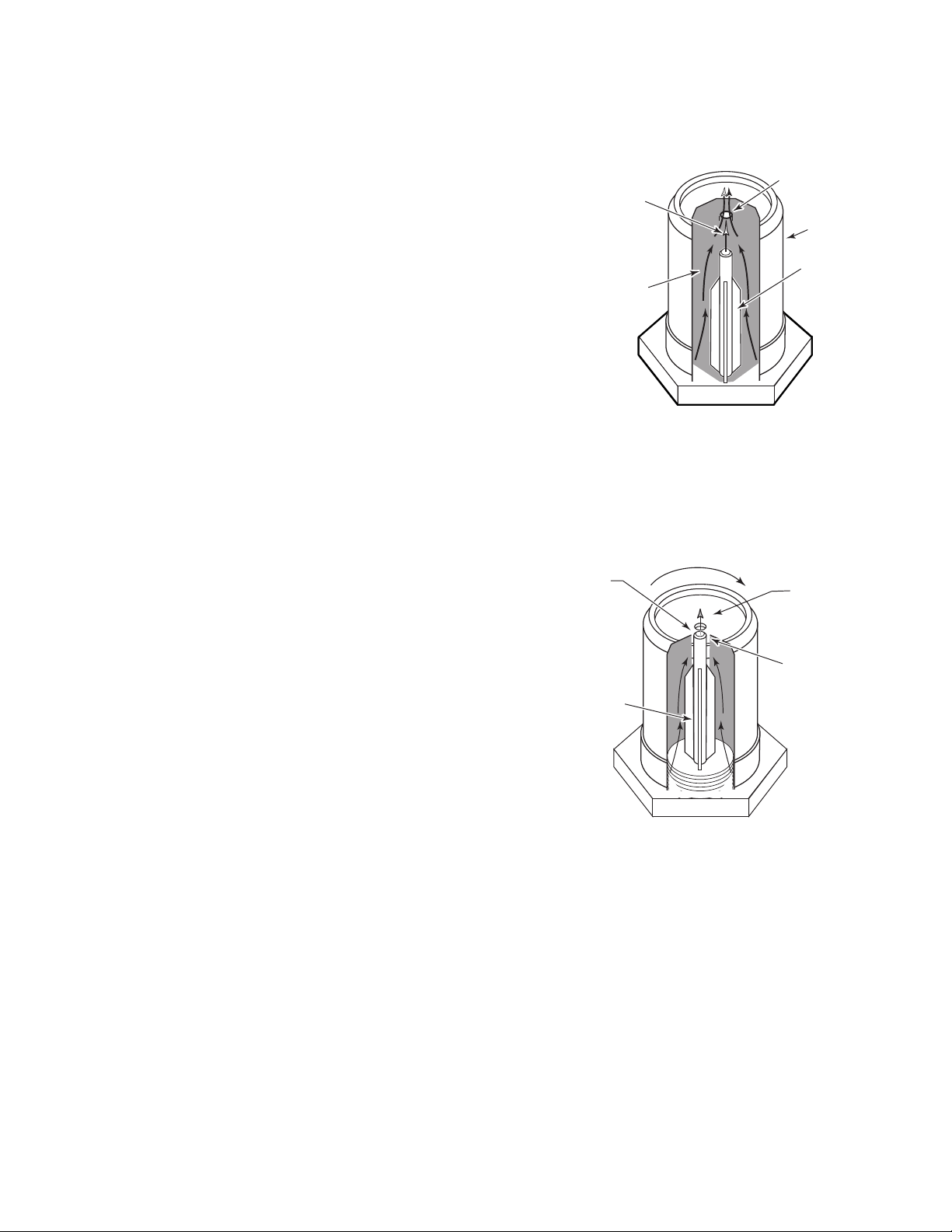
UNIVERSAL ORIFICE—OVEN APPLICATION
Gas From
L.P. Insert
Gas
Through
Cap Is
Blocked
L.P. Position
Cap Rests
Against
L.P. Insert
L.P. Insert
Gas cooking systems for both L.P. gas and natural gas
can be used without changing orifices by using a
sal
orifice.
The universal orifice consists of an L.P. gas insert that is
threaded into a cap orifice. This insert is actually an
orifice itself. When natural gas is used, the cap is in the
position shown in Figure 3-7. Gas enters through both
the cap and the insert. The amount of gas leaving the
orifice is controlled by the size of the cap orifice.
When L.P. gas is used, the cap is tightened down
2-1/2 turns so that it rests against the L.P. insert,
closing off the spacing between the two (see Figure
3-8). The amount of gas leaving the orifice is now
controlled by the size of the L.P. insert.
univer-
Natural Gas Position
Cap Orifice
Gas Flow
Cap
Insert
Gas Flow
Figure 3-7
Figure 3-8
Page 3-5
Page 24

GAS VALVE ORIFICE DIAGNOSTICS
A gas valve orifice is often a source for gas range problems. Some of the problems that arise with
an orifice are as follows:
1. The orifice may become clogged from dirt, or slag in the gas lines. The result will be an overrestricted gas flow, causing the mixture to become too “lean”. This means that not enough gas
will be mixed with air in the burner for efficient burning to occur.
2. The orifice may become cross-threaded when it is installed and allow one of three conditions
to occur:
a) The orifice may not be aligned correctly with the venturi tube so that the gas flows straight
into the burner, causing inefficient burning.
b) The orifice may not be secured because of the cross-threading, causing a small gas leak.
The mixture will again be too lean, and inefficient burning will occur.
c) The orifice size may be incorrect. If a conversion is made from natural to L.P. gas, the orifice
must be changed to maintain the desired heat output. The orifice size may also be too small
due to a high consumption rate, so that the burner cannot meet its maximum B.T.U. output.
If it becomes necessary to clean an orifice, there are three methods that can be used:
1. Blowing forced air into the chamber.
2. Using a mild solvent and soaking the orifice for 15 to 30 minutes (the orifice can then be blown
out and reinstalled).
3. Using a drill bit to clean the orifice. The bit is inserted into the orifice, then, using a slow in and
out motion, the debris can be removed. A chart on page 3-4 shows the proper drill bit size to
use for a particular orifice.
Page 3-6
Page 25

PERFORMANCE CHECK
1. Remove the gas valves.
2. Remove the orifices.
Page 3-7
Page 26
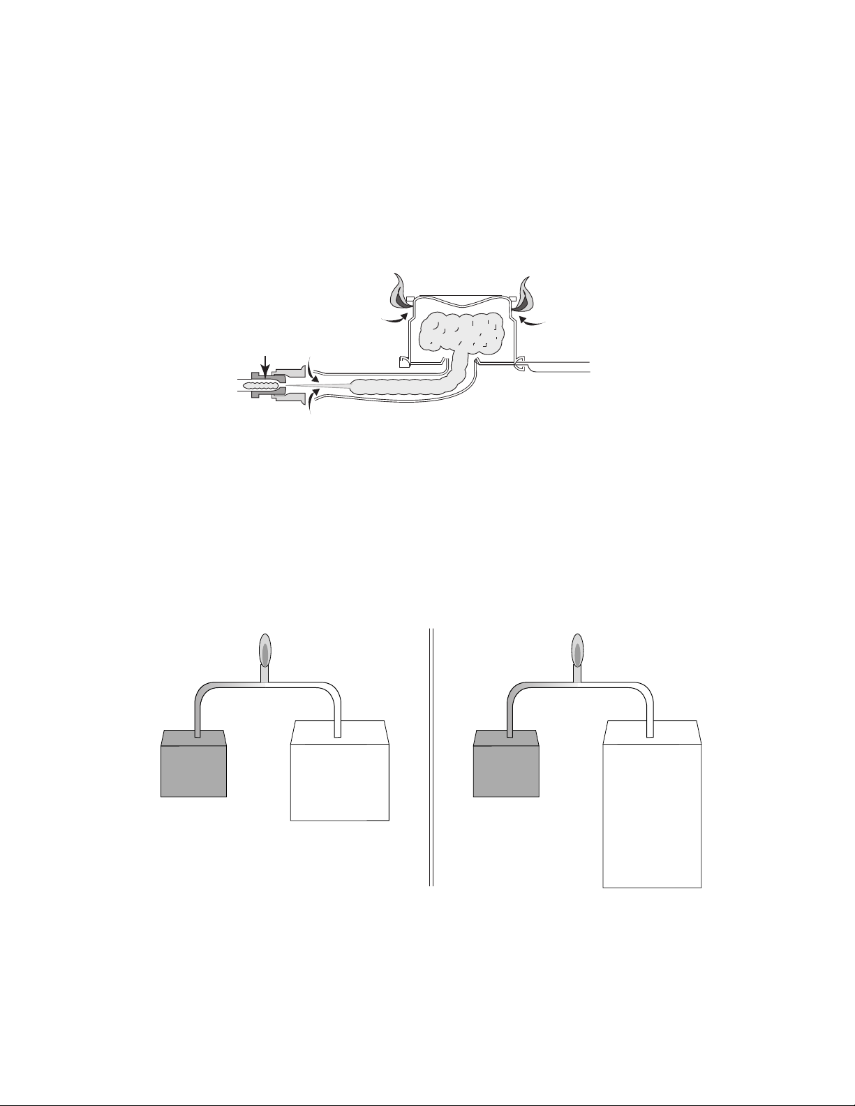
BURNER OPERATION
To understand how a burner operates, it is important to understand the following terms (see Figure
3-9):
Gas:
Primary Air:
Secondary Air:
Air/Gas Ratio:
The fuel used by the burner, either natural or L.P.
The air mixed with the gas in order to make the gas combustible.
The supplemental, or ambient air, surrounding the flame.
Comparison of amounts of fuel gas and air to act as primary and
secondary air.
Secondary Air
Gas
Primary Air
Primary Air
Figure 3-9
For proper operation, a burner needs the correct amount of gas mixed with the correct amount of
air, referred to as the “air/gas ratio.” A correct air/gas ratio will result in a flame that is stable without
yellow tips. The ratio depends upon the fuel gas type being used. Ten cubic feet of air are needed
to completely burn one cubic foot of natural gas (10 to 1 ratio) and twenty-four cubic feet of air are
needed to completely burn one cubic foot of L.P. gas (24 to 1 ratio). (See Figure 3-10).
When broken down, 70% to 80% of the total air required is mixed with the gas as primary air. The
remaining 20% to 30% is pulled into the flame as secondary air.
1000 BTU Heat
1 cu.ft.
Gas
Natural Gas
10 cu. ft. Air To 1 cu.ft. Gas
10 cu.ft.
Air
Figure 3-10
1000 BTU Heat
1 cu.ft.
Gas
L.P. Gas
24 cu. ft. Air
To 1 cu.ft. Gas
24 cu.ft.
Air
Page 3-8
Page 27
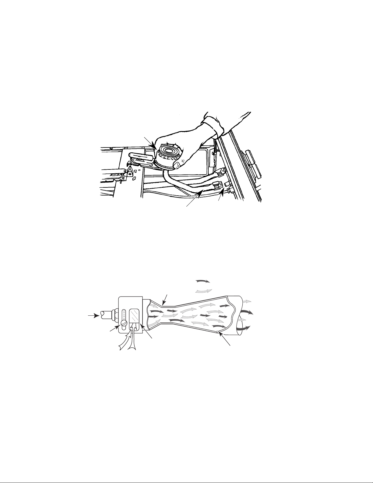
The
Cooktop Burner Assembly
controls the combustion of gas and directs its flame (see Figure
3-11). Burners are manufactured from galvanized steel and have common component parts:
1. An
2. A
Air Shutter
Venturi
to provide a pathway for gas to flow to the burner from the orifice. Air enters the
to control the amount of primary air to be mixed with the gas.
burner through the venturi tube, and is used as a pathway for gas, as well as an area for gas
and air to be mixed together for combustion.
3. A
Burner Head
to provide an exit for gas so it can be ignited. The exits are normally holes,
or slots, called “burner ports.”
Burner Head
Figure 3-11
Venturi
Air Shutter
AIR SHUTTER & VENTURI
An inlet for primary air is provided before the gas supply reaches the burner port. This inlet is called
an “air shutter” (see Figure 3-12). The air shutter is adjustable to allow a better adjustment of the
air-gas mixture needed for combustion, and results in more efficient combustion.
Gas Inlet
Adjustment
Screw
Venturi
(Constricting
Area)
Adjustable
Air Shutter
Primary Air
= Gas
= Air
Expanding
Area
Mixed Air &
Gas Outlet
Figure 3-12
Page 3-9
Page 28
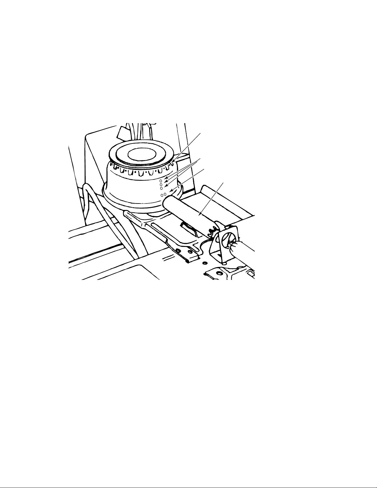
BURNER HEAD
When gas leaves the orifice, it passes through the venturi, and is forced into the burner head. As
the gas passes between the orifice and the burner head, primary air is mixed with the gas to form
a combustible mixture. The burner head disperses the gas/air mixture for ignition.
In addition to the burner ports at the top of the burner head, there are also ports along the side of
the burner, called
to be ignited by the pilot flame. The climber ports allow the flame to climb the side of the burner head
and ignite the gas at the top ports.
charge ports
and
climber ports
. The charge ports inject gas down the flash tube
Top Burner Ports
Climber Ports
Charge Ports
Flash Tube
Figure 3-13
Page 3-10
Page 29

FLAME CHARACTERISTICS
A Properly Burning Flame
A properly burning flame has an inner cone, an outer cone, and an outer envelope. These three
parts should be definable and distinguishable, although the outer envelope may not be easy to see.
(see Figure 3-14).
The inner cone is the point where the air/gas mixture ignites and the combustion process begins.
High levels of Carbon Monoxide and Aldehydes are produced in this cone.
Outer Envelope
Proper Flame Characteristics:
• Blue Color
• Flame Seated On Burner Port
• Well Defined Shape
The outer cone surrounds the inner cone. The outer cone is the hottest part of the flame. Secondary
air is drawn into the flame at this point and accelerates combustion. As the by-products from the
inner cone move into the outer cone, they are burned and transformed into harmless water vapor
(H2O) and Carbon Dioxide (CO2). If there is not enough secondary air, or if it is poorly ventilated
and stagnant, this process cannot occur completely, and some of the harmful by-products from the
inner cone will skip into the outer envelope.
Unburned Air/Gas
Inner Cone
Outer Cone
Figure 3-14
The outer envelope surrounds the outer cone. The combustion process has been completed by
the time the chemicals reach this point. The glow of the envelope is the result of the hot Carbon
Dioxide and Water Vapor exiting the outer cone.
Too Much Primary Air
As the primary air is increased, the gas/air mixture burns at a faster speed (like fanning a flame).
The additional primary air results in a greater volume of air/gas flow through the burner ports.
With increased delivery pressure and a faster burning flame, the result is a flame that blows straight
out of the burner and burns with a sound similar to a blow torch. The flames lift off the burners and
the cone structure of the flame is disrupted. (see Figure 3-15).
Outer Envelope
Outer Cone
Flame Lifts
Off Burner
Inner Cone Pushes
Through Outer Cone
Figure 3-15
Page 3-11
Page 30
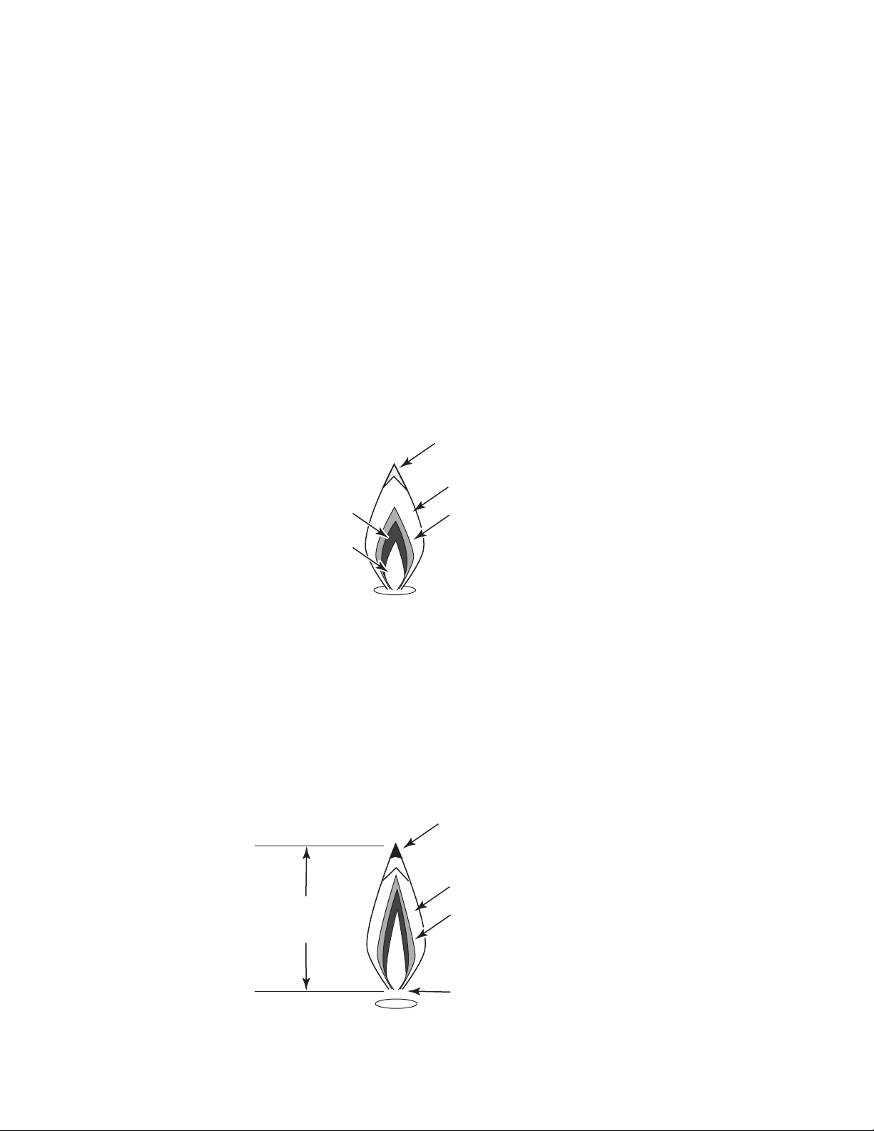
The inner-cone combustion process will occur in increased levels, and will release more of the
harmful by-products, CO and Aldehydes. The level of secondary air will no longer be enough to
2
convert these chemicals into the safe by-products CO
and H2O, and there will be higher levels of
dangerous chemicals released into the room.
NOTE: It is normal for the burners without mixing tubes to have blowing flames during the first
minute of operation. When the burner is cold, primary air injection is increased. Once the burner
heats, the injection of primary air is reduced and the flames settle.
Not Enough Primary Air
The reduction of primary air slows the burning process and results in the inner cone rising higher
in the flame. Less burning takes place in the inner cone. A larger amount of the by-products that
would be consumed in the inner cone pass into the outer cone.
The size of the outer cone is also reduced by the lack of primary air. The outer cone cannot consume
the volume of by-products flowing from the inner cone. A percentage of these by-products flow into
the outer envelope where the carbon content of the by-product is burned, causing the flame to have
yellow tips (see Figure 3-16).
Yellow Tipping In
Outer Envelope
Outer Envelope
Inner Cone
Outer Cone
Unburned
Air/Gas
Figure 3-16
Over-Fueled Burner
Over-fueling of the burner can be caused by one of three common causes:
• Excessive gas pressure entering the burner
• The BTU rating of the gas can be too high for the burner
• An oversized gas metering orifice
It is difficult to recognize the difference between an over-fueled burner and too much primary air.
In both cases, the burner flame length extends too far off of the burner (see Figure 3-17).
Yellow Tipping
And Soot Can Appear
In Extreme Cases
Outer Envelope
Flame
Too Tall
Outer Cone
Page 3-12
Flame Lifts
Off Burner
Figure 3-17
Page 31
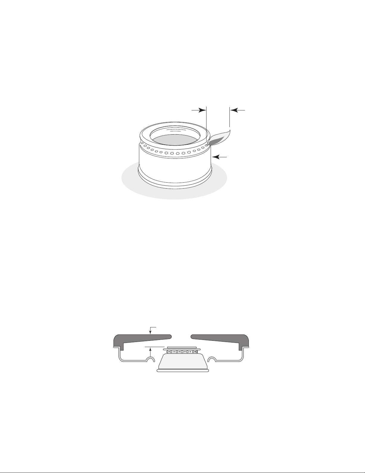
The over-fueled burner has more of a normal flame structure and less of a blowing noise than a
burner with too much primary air. The easiest way to determine whether the burner is over-fueled
is to vary the air shutter opening size. If the flame length can be reduced to the correct size and
structure by adjusting the air shutter, then the problem is not an over-fueled burner.
Top burners should have a cone length of approximately 5/8" (see Figure 3-18).
For L.P. installations and models without adjustable orifices, the orifice must be replaced with a
recommended L.P. sized orifice.
Outer Cone
5/8
"
Cooktop
Burner
Figure 3-18
Flame Quenching
Flame quenching occurs when the flame is cooled before complete combustion occurs. Placing
an object, such as an oven flame spreader into the flame, will cool or quench the flame, resulting
in incomplete combustion. The object interrupts the combustion process and releases the
unburned by-products from the inner or outer cone of the flame.
The height of the surface burners in relation to the burner grates should always be closely
examined and measured. If the burner is too close to the grate or too close to the maintop,
quenching can result and possibly cause damage to the maintop.
Top burners can be bent out of adjustment easily by putting excessive weight on them, for example,
by leaning on them. The distance from the highest point of the burner to the top of the grate should
be approximately 3/4" (see Figure 3-19).
3/4
"
Figure 3-19
Page 3-13
Page 32
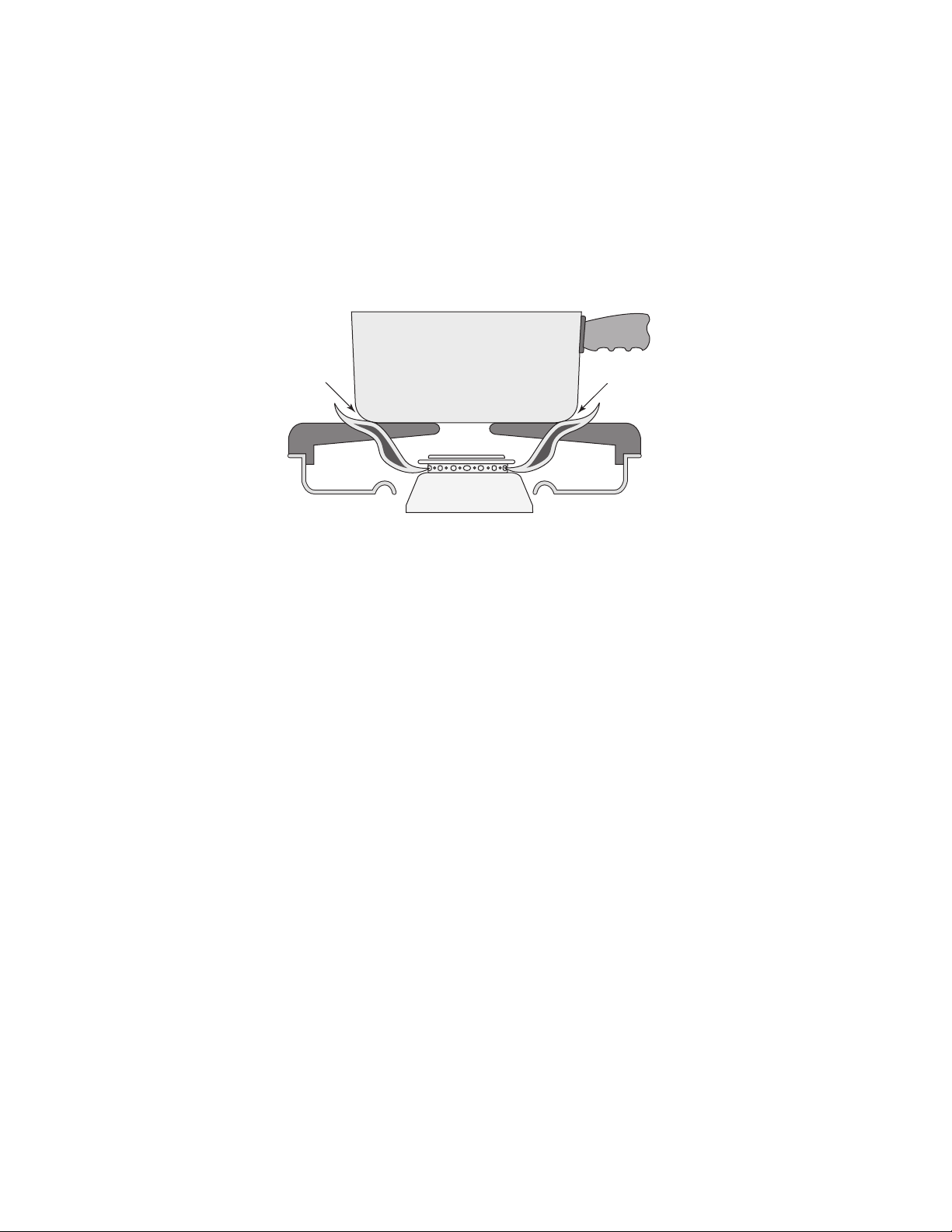
In the case of an over-fueled burner, the excessive length of the flames can result in the quenching
at the oven flame spreader or top burner grate even though the flame spreader and grate may be
at the proper distance. Check for this before adjusting the burners.
When quenching occurs, (see Figure 3-20), the customer may complain of a chemical odor. This
odor results from the Aldehydes being released from the flame as one of the by-products of
incomplete combustion. Some customers may associate this odor with a gas smell, but the two
odors are quite different. By examining the flame length between the burners and other
components, and by looking for an out of place component, the cause of the quenching can easily
be located.
Flame Quenching
Flame Quenching
Figure 3-20
Page 3-14
Page 33

IMPROPER FLAME DIAGNOSTICS
For any of the improper flames discussed, refer to the following chart for the appropriate corrective
actions. In most of the malfunctions described thus far, the burner flames will change characteristics when a problem develops. However, there are times when the symptom of a burner problem
is an unusual noise. The noise may be a “rumbling” or “gurgling” sound or a “high pitched squeal”
or “burr.” In any event, the table lists burner noise malfunctions and their respective causes and
corrective actions.
Symptom Cause
Flame is white-blue and has hard,
sharp features.
Flame is small and blue in color. 1. Clogged burner orifice.
Flame is yellow. 1. Insufficient primary air.
Flame is noisy (rumbles or
gurgles).
Orifice noise (burr or high-pitched
squeal).
Excessive primary air.
2. Clogged venturi.
3. Restricted or clogged gas line.
4. Excessive low gas pressure.
2. Blocked primary air shutter.
3. Oversized burner orifice.
1. Excessive primary air.
2. Excessive gas pressure.
1. Debris lodged in orifice.
2. Improper orifice size.
3. Excessive gas pressure.
Corrective Action
Adjust air shutter.
1. Clean or replace burner orifice.
2. Clean venturi. Replace burner, if
necessary.
3. Remove & clean the gas supply
line. Relace, if necessary.
4. Use a manometer and adjust the
gas pressure.
1. Adjust primary air shutter.
2. Clean primary air shutter &
adjust for proper air-gas mixture.
3. Replace burner orifice.
1. Clean primary air shutter &
adjust for proper air-gas mixture.
2. Use a manometer and adjust the
gas pressure.
1. Clean orifice. Replace, if
necessary.
2. Replace orifice.
3. Use a manometer and adjust the
gas pressure.
Air intake or mixing noise.
Erratic burner flame (fluctuates
high to low).
1. Rough area in mixing tube or
venturi.
2. Loose debris in mixing tube or
venturi.
3. Burner not seated correctly over
orifice. Distance between orifice
and venturi too large.
1. Gas regulator flutter.
2. Control valve malfunction.
Page 3-15
1. Smooth interior surface. Replace
burner, if necessary.
2. Clean mixing tube.
3. Seat burner over orifice.
1. Replace pressure regulator, if
necessary.
2. Adjust regulator on control valve.
Replace, if necessary.
Page 34
CLEANING THE BURNERS
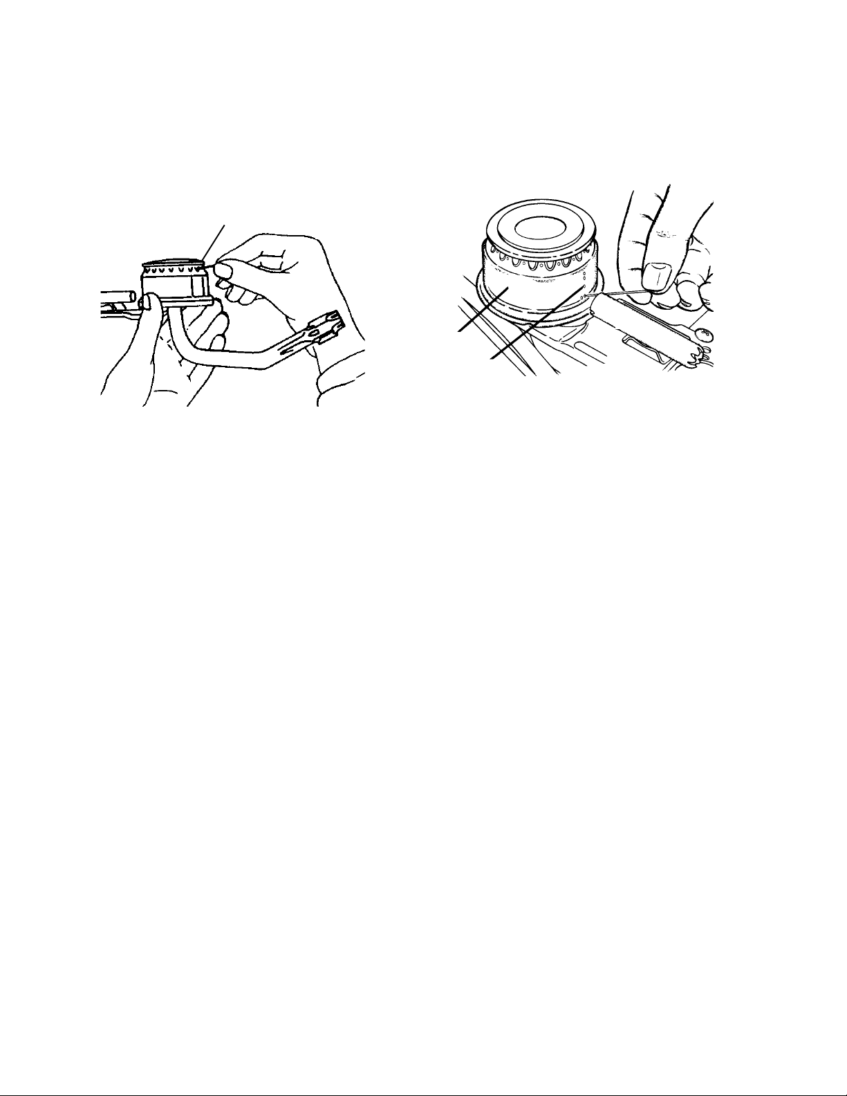
The most common burner maIfunction is clogging due to excess dirt and debris, which can enter
the burner through the burner ports. This excess dirt can block one or several of the ports so that
the burner will have trouble lighting, or will not light at all. In this case, the burner ports must be
cleared using a pin (see Figures 3-21 and 3-22).
Port
Burner
Climber Port
Figure 3-22
Figure 3-21
The primary air shutter is an additional inlet where dust can enter a main burner. Whether or not
the burner is operating, dust can still be drawn into the burner through the air shutter. The debris
can clog the venturi, orifice, or burner ports. Again, this type of clogging can reduce, if not stop, the
flow of gas through the burner. In addition, the primary air shutter itself can become blocked,
restricting the flow of primary air into the burner.
In any event, cleaning the burner normally eliminates most of the dirt buildup. Also, it is a good
practice to keep the area immediately surrounding the main burner as clean as possible to reduce
the possibility of clogging any part of the main burner.
Page 3-16
Page 35
STANDING PILOT IGNITION SYSTEM
OPERATION
The ignition system provides heat, which is the third element necessary for combustion. Whirlpool
ranges use two different processes to provide this element. The first process is a standing pilot
ignition, and the second is an electronic ignition.
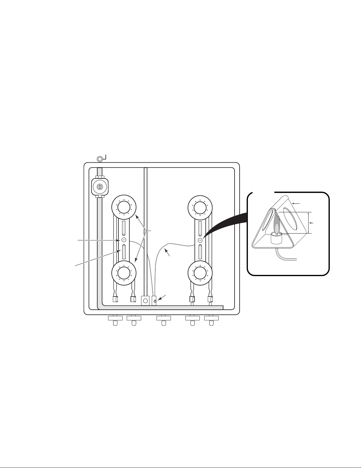
The primary purpose of a standing pilot is to ignite the main burner. Pilot assemblies consist of a
gas supply tube and an adjustment screw that controls the amount of gas flow to the pilot.
To produce a pilot flame, gas is supplied through the gas supply tube (see Figure 3-23), and
directed toward the pilot opening, or port. As the gas is available it is manually lit. The pilot flame
is usually set to a height of approximately 1/4". This is accomplished by turning the pilot adjustment
screw until the desired flame is produced (see the inset). The flame should have a distinct blue
body.
Inset
Bracket
Pilot Flame
or Spark Ignitor
Flash Tube
Burner
Heads
Gas Supply
Tube
Pilot
Adjustment
Screw
Figure 3-23
1/4"
Flame
Pilot Flame Size
Page 3-17
Page 36
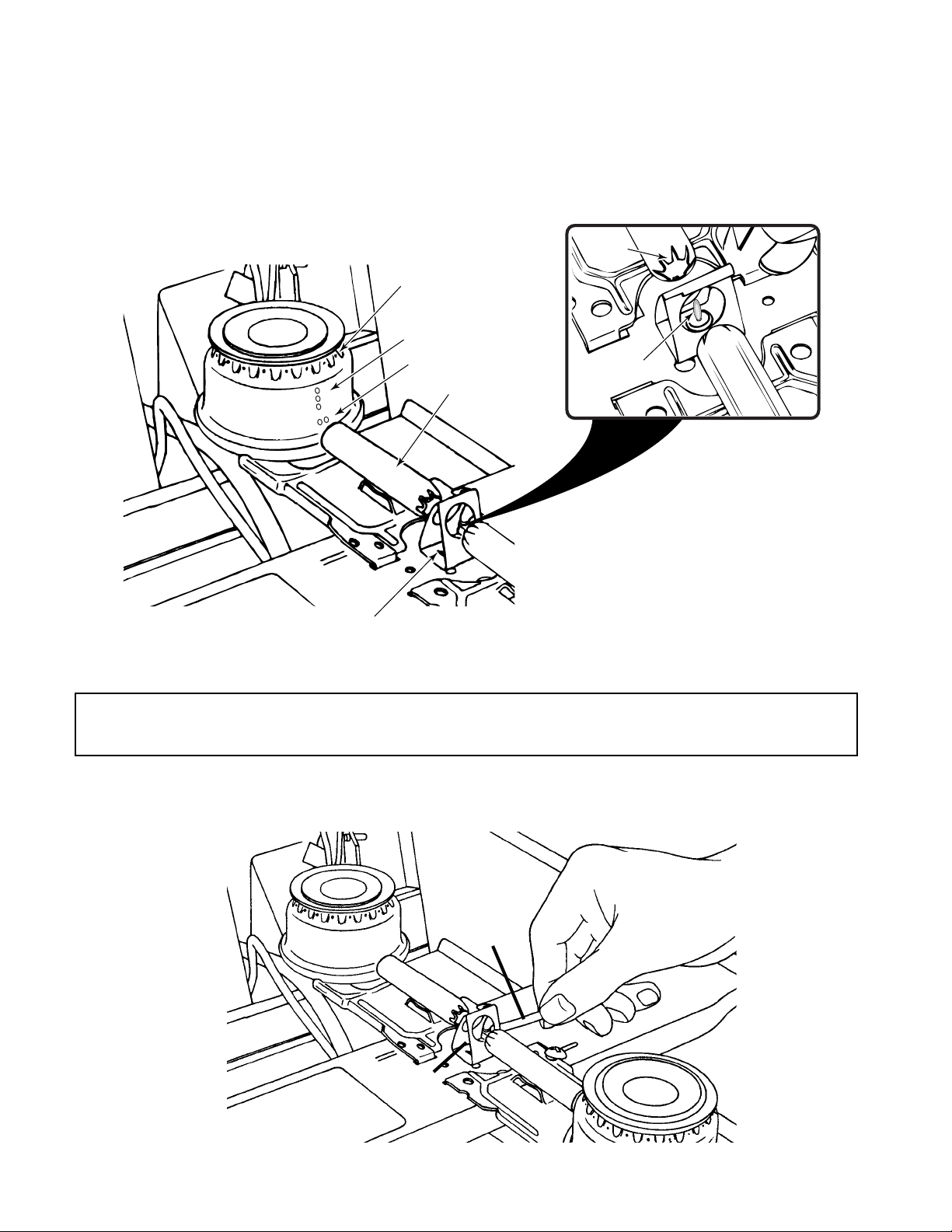
When the gas control valve is turned on, gas flows to the burner head, and out the ports. There are
ports at both the top and side of the burner head, as shown in Figure 3-25. The side ports direct
gas to a
flash tube
, where it is drawn through the tube to the pilot flame, where it is ignited inside
the tube. The ignited gas is then flashed back to the main burner, where gas from the top ports is
ignited by the pilot flame. The burning gas from the pilot also helps to draw gas through the tube
for combustion.
Flash
Tube
Top Burner Ports
Climber Ports
Charge Ports
Flash Tube
Pilot Flame
Figure 3-25
Pilot Flame (Inside Shield)
RELIGHTING A STANDING PILOT
Caution: If the pilot has been out for some time and you detect a strong odor of gas,
ventilate the room before trying to relight the pilot.
Turn off all range controls and prop open the cooktop. Place a lighted match near the opening of
the pilot, located midway between two burners, as shown in Figure 3-26. If the pilot does not stay
lit, clean, or adjust it.
Match
Pilot
Figure 3-26
Page 3-18
Page 37
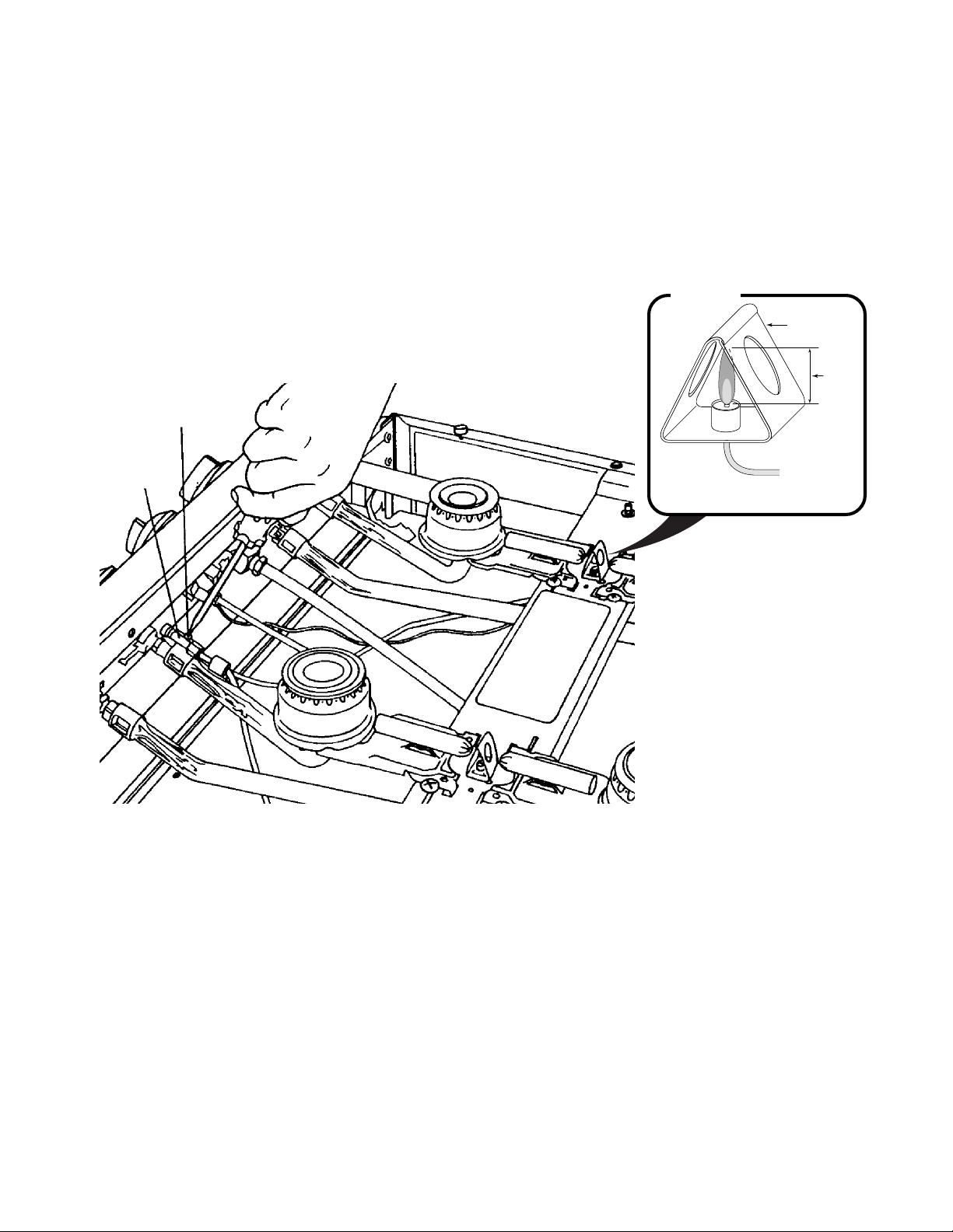
ADJUSTING THE PILOT FLAME HEIGHT
A pilot that frequently blows out may be set too high, or too low. To adjust the pilot flame to the
correct height, perform the following steps:
1. Turn off the controls and prop open the cooktop.
2. Using a screwdriver, turn the needle valve screw slowly in the direction necessary to set the
size of the pilot flame, as shown in Figure 3-27. The flame should have a sharp, blue cone that
is approximately 1/4" high, as shown in the inset.
3. Lower the cooktop.
Adjustment
Screw
Pilot
Gas Line
Inset
Bracket
1/4"
Flame
Proper Flame Size
Figure 3-27
Page 3-19
Page 38
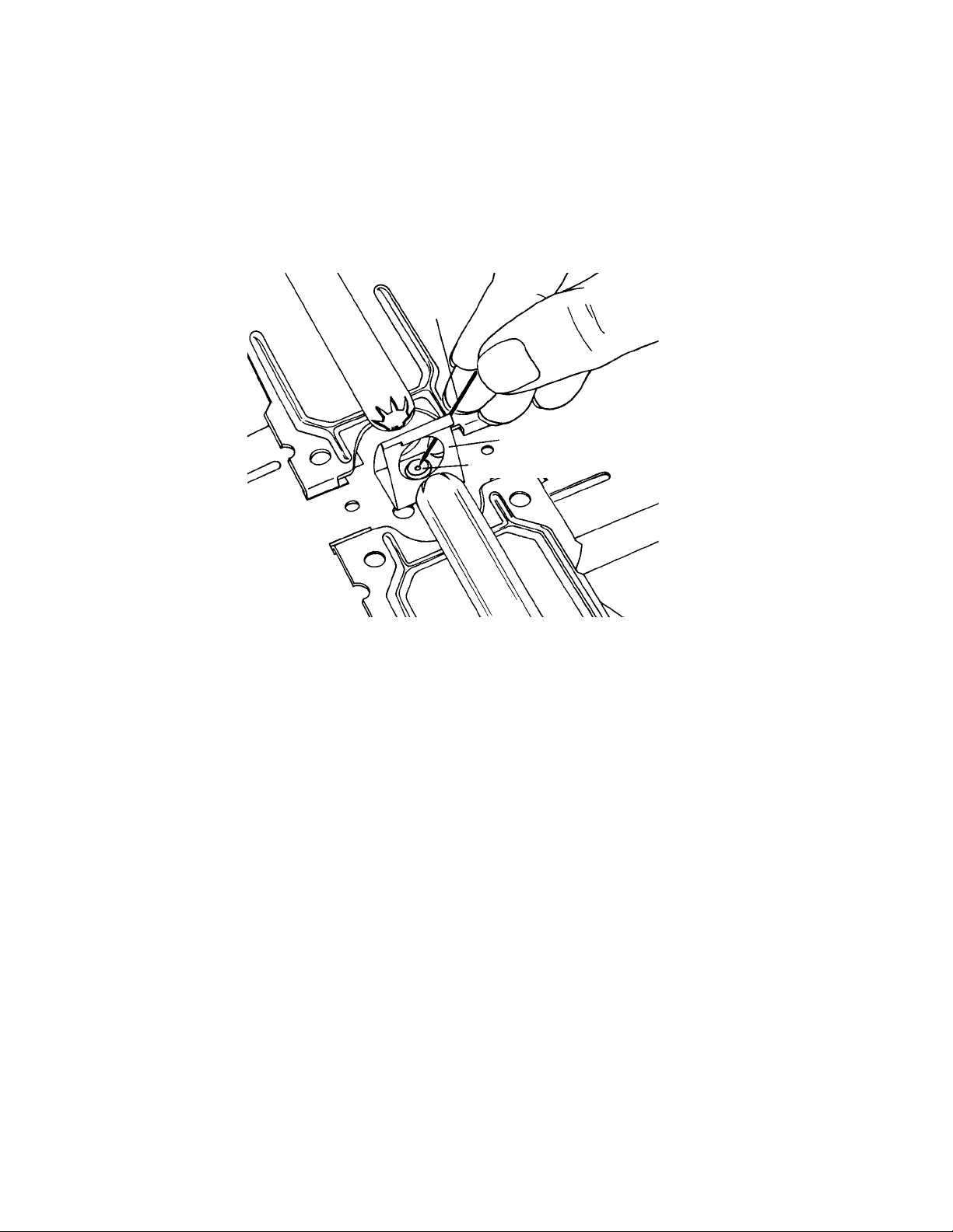
CLEANING THE PILOT
The small opening of a pilot can easily become clogged with dust, grease, or food, preventing
proper gas flow. A pilot that will not light, or will not stay lit, may simply need to be cleaned.
To clean the pilot, insert a straight pin into the pilot opening, as shown in Figure 3-28, and move
it up and down gently, being careful not to enlarge or deform the opening. If there is a protective
metal shield over the pilot that prevents you from reaching the opening, remove it by pressing in
on the tabs on either side, and unhooking it.
Straight
Pin
Shield
Pilot Opening
Figure 3-28
Page 3-20
Page 39
ELECTRONIC IGNITION SYSTEM
OPERATION
The
Electronic Ignition System
However, instead of using a standing pilot flame to ignite the main burners, a spark from a surface
burner ignitor is used.
The electronic ignition system consists of the following components:
1. Ignitor Switches
2. Ignitor Spark Module
3. Surface Burner Ignitors (electrodes)
performs the same function as the standing pilot ignition system.
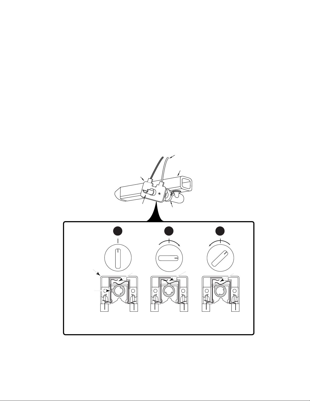
Ignitor Switches
control the voltage to the ignitor spark module by opening and closing the circuit.
The ignitor switches are mounted on the stem of each burner control valve, and are rotary-actuated.
There are two types of switches used on Whirlpool ranges. One is for a 90˚ valve, shown in Figure
3-29, and the other is for a 220˚ valve. Each gas valve has its own ignitor switch. The ignitor
switches are wired in parallel.
TO IGNITOR SPARK MODULE
MANIFOLD
IGNITOR SWITCH
STEM
GAS VALVE
1 2 3
LITE
ON
OFF
Contacts
Open
Ignitor Switch
ON
LITE
OFF
Contacts
Open
LITE
ON
90˚
OFF
Contacts
Closed
Rotating
Collar Stop
Burner Off
Switch Contacts Open
Burner Off
Switch Contacts Closed
Ignitors Sparking
Figure 3-29
Page 3-21
Burner Off
Switch Contacts Open
Burner Lit
Page 40
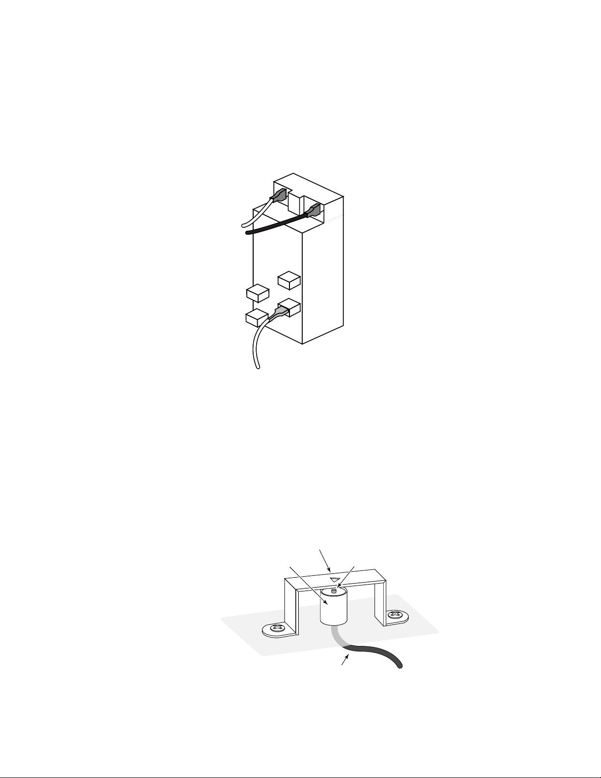
The
Ignitor Spark Module
is a solid-state device that is used to provide high voltage for the top
burner ignitors (see Figure 3-30). Whenever the ignitor module is energized by one of the ignitor
switches, a solid state circuit and pulse transformer within the module electronically increases the
constant AC line voltage to periodic high voltage pulses, and sends these pulses to all of the ignitor
electrodes at the same time. The pulses will be sent to the ignitors at about 2 pulses (sparks) per
second. There are no adjustments that can be made to the module and it is serviced only as an
assembly. The system operates at very low amperage (4 milliamps) so that the high voltage
pulses, or sparks, present no severe shock hazard.
TO IGNITOR
SWITCHES
IGNITOR
SPARK
MODULE
Figure 3-30
TO SURFACE BURNER IGNITOR
A
Surface Burner Ignitor
is a metal rod with a ceramic insulating body that is wired directly to the
ignitor spark module. Pulses from the ignitor module cause the ignitor to arc to the ground strap
(see Figure 3-31). These pulses, or sparks, light the top burners through the flash tube.
The surface burner ignitors are manual ignitors that spark whenever a burner valve is in the “lite”
position. The module will continue to send pulses to the ignitor until the valve is turned to any
position other than “lite.”
Since the system operates on high voltage pulses sparking to ground, it is very important that the
range be properly grounded, and that chassis ground through the range is continuous.
Ground Strap
Ceramic
Insulated Body
(Bracket)
Metal Rod
Figure 3-31
Electrode Wire
Page 3-22
Page 41
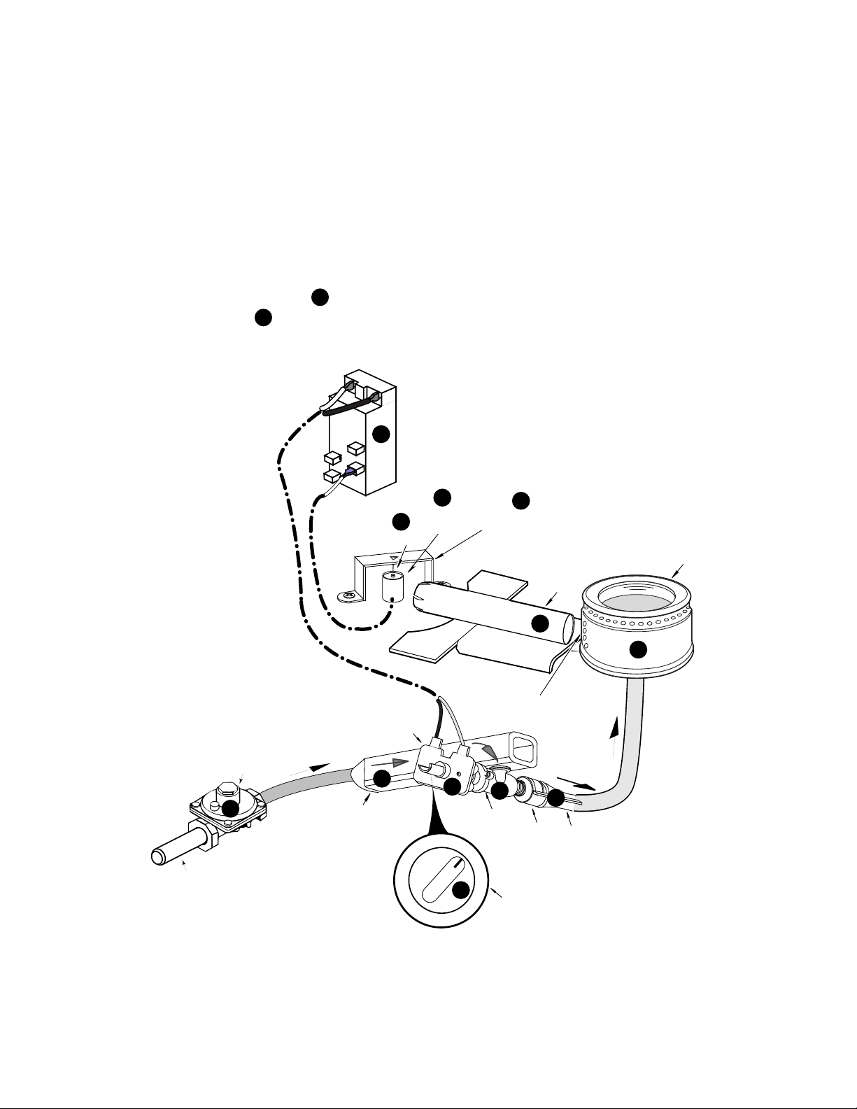
Refer to Figure 3-32 for the following sequence.
CONVENTIONAL BURNER
When a main burner control knob q is turned to the “lite” position, the gas valve r opens, and
gas flows through the pressure regulator s into the manifold t through the open valve. As gas
passes through the valve and its orifice, it is directed into the venturi u, where it mixes with
primary air to create the proper mixture necessary for combustion.
At the same time, line voltage is applied through the ignitor switch v, to the ignitor spark module
w, which produces high-voltage pulses to all of the spark ignitors x. The pulses cause a spark
y to occur between the spark ignitor electrode, and the ground strap (bracket) z. The gas and
air mixture at the burner head, flows through the three climber ports in the side of the head,
and into the flash tube . As gas flows through the flash tube, it is ignited by the spark. The
12
combusted gas flashes back through the tube, and ignites the burner.
120 VAC
LINE VOLTAGE
11
HIGH
VOLTAGE
PULSES
7
SPARK
IGNITOR
SPARK
MODULE
SPARK
9
IGNITOR
8
10
GROUND STRAP
(BRACKET)
BURNER
FLASH
TUBE
PRESSURE
REGULATOR
GAS INLET
12
11
CLIMBER
IGNITOR SWITCH
GAS FLOW
4
3
GAS
MANIFOLD
OFF
6
GAS VALVE
LITE
PORTS (3)
2
SHUTTER
AIR
GAS FLOW
5
VENTURI
Figure 3-32
1
BURNER
CONTROL
KNOB
Page 3-23
Page 42
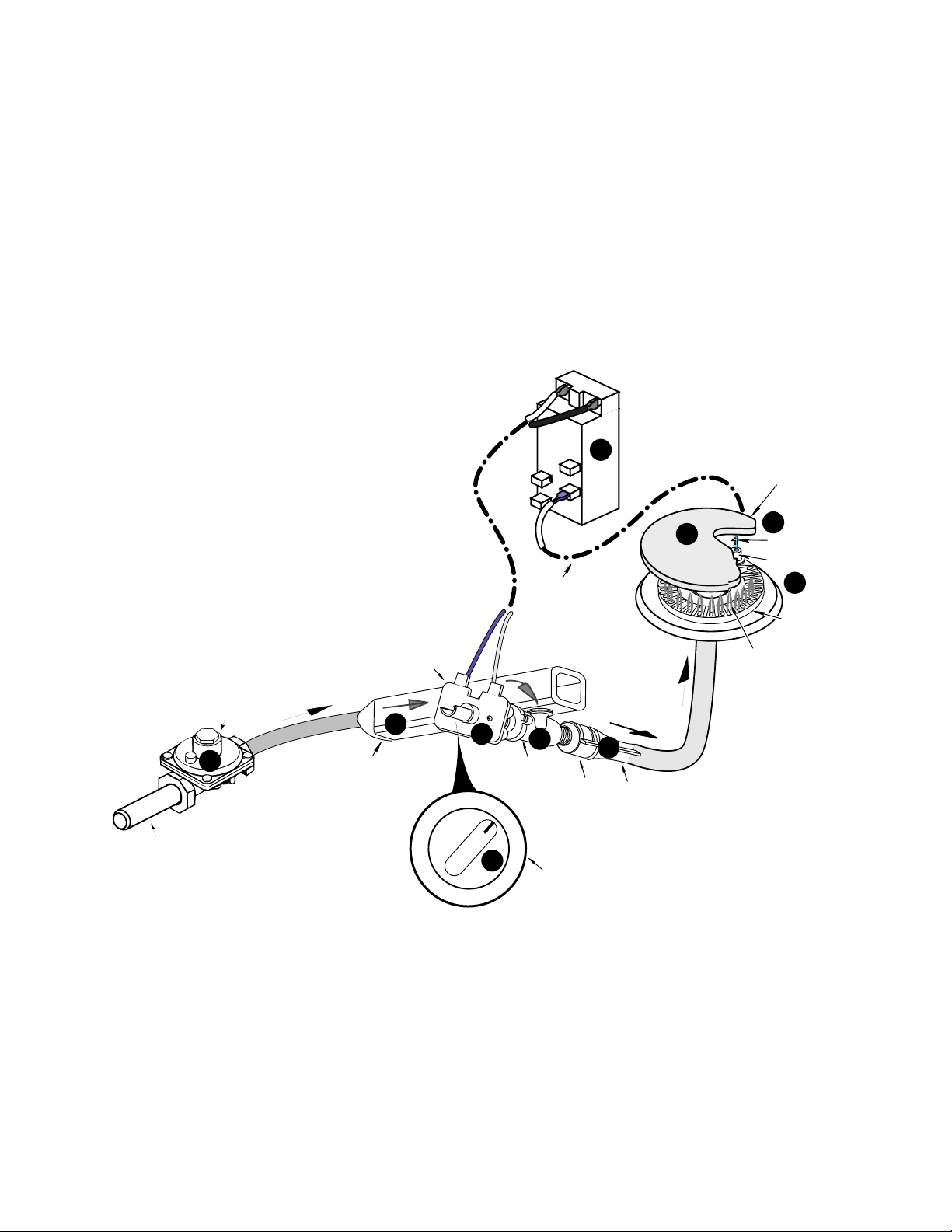
Refer to Figure 3-33 for the following sequence.
SEALED BURNER
When a main burner control knob q is turned to the “lite” position, the gas valve r opens, and
gas flows through the pressure regulator s into the manifold t through the open valve. As gas
passes through the valve and its orifice, it is directed into the venturi u, where it mixes with
primary air to create the proper mixture necessary for combustion.
At the same time, line voltage is applied through the ignitor switch v, to the ignitor spark module w, which produces high-voltage pulses to all of the spark ignitors x. The pulses cause a
spark y to occur between the spark ignitor electrode, and the grounded burner cap z. The
gas and air mixture at the burner head is ignited by the spark, and a flame is produced at each
of the top burner ports.
IGNITOR
SPARK
MODULE
7
HIGH VOLTAGE
PULSES
BURNER CAP
GAS INLET
PRESSURE
REGULATOR
3
GAS FLOW
IGNITOR SWITCH
GAS
MANIFOLD
4
120 VAC
LINE VOLTAGE
6
OFF
LITE
1
TO SPARK
IGNITOR
2
GAS VALVE
AIR SHUTTER
BURNER
CONTROL
KNOB
GAS FLOW
5
VENTURI
10
BURNER FLAME
Figure 3-33
9
SPARK
SPARK
IGNITOR
8
BURNER
Page 3-24
Page 43

ELECTRONIC IGNITION DIAGNOSTICS
Problems with electronic ignition systems usually occur in one of two ways: the electrode will not
spark, or the sparking will not stop.
If the ignitors are in series, and one is not sparking, none will spark. Also, all spark ignitors use the
same ignitor spark module, but different switches. If one burner is not igniting while the gas valve
is still open to that burner, turn on another burner that does not share the same ignitor. In this way
you can isolate the problem to the switch, the spark ignitor, or the ignitor spark module.
To check for a bad ignitor switch, pull the leads from the switch, touch the bare lead ends together,
and see if the ignitor sparks. CAUTION: When testing these switches, do not forget that they
operate on 110 volts, so do not touch the lead ends, or you will receive an electrical shock.
Use a pair of insulated needle nose pliers to pull the leads off the switch.
If the ignitors will not stop sparking, usually one of the ignitor switches has shorted. A short is usually
caused by moisture getting into the switch contacts. To determine the defective switch:
1. Pull one lead off each switch, one at a time, until the sparking stops.
2. Pull the defective switch off the control valve, and replace it.
A defective ignitor spark module can also cause a “no spark” condition. If none of the ignitor
switches seem to be defective, replace the ignitor spark module.
Page 3-25
Page 44

PERFORMANCE CHECK
1. Remove the burners.
2. Remove the ignition system (ignitor spark module, ignitor switches, and surface burner
ignitors).
Page 3-26
Page 45
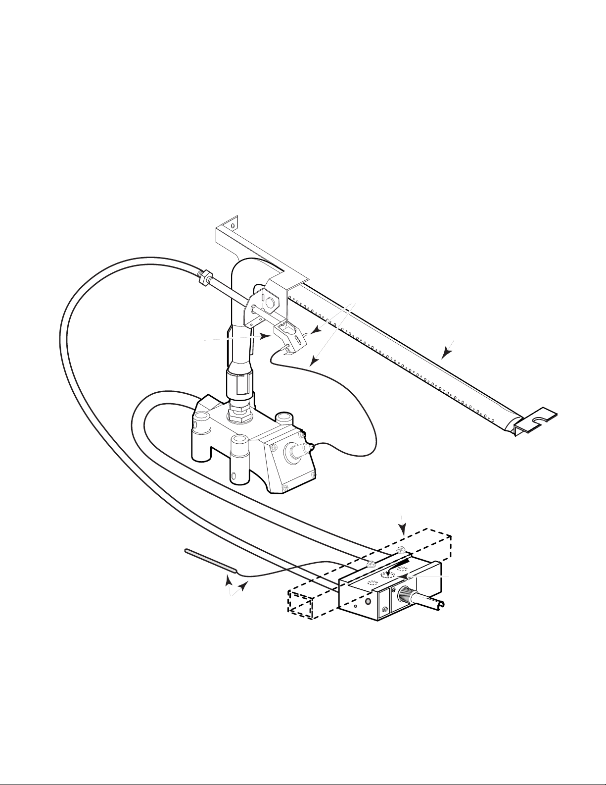
THE OVEN BURNER SYSTEM
STANDING PILOT IGNITION
The complete
Standing Pilot Ignition System
(see Figure 4-1) is controlled by two very important
mechanical components. The first is a thermostat that is mounted on the manifold pipe and
accessible to the customer, and the other is an oven safety valve that controls the gas flow into the
oven burner. If either of these components is not working properly, the system will not function. The
burner, air shutter, and venturi are also critical components, and work the same as on the cooktop
burners that were discussed in Section 3.
Pilot Gas Line
Pilot Flame
Sensing Bulb &
Capillary Tube
Oven
Pilot
Assembly
Main Gas Line
Burner
Sensing Bulb &
Capillary Tube
Safety
Valve
Figure 4-1
Page 4-1
Manifold
T
OFF
A
N
P
L
Thermostat
Gas In
Oven
Page 46
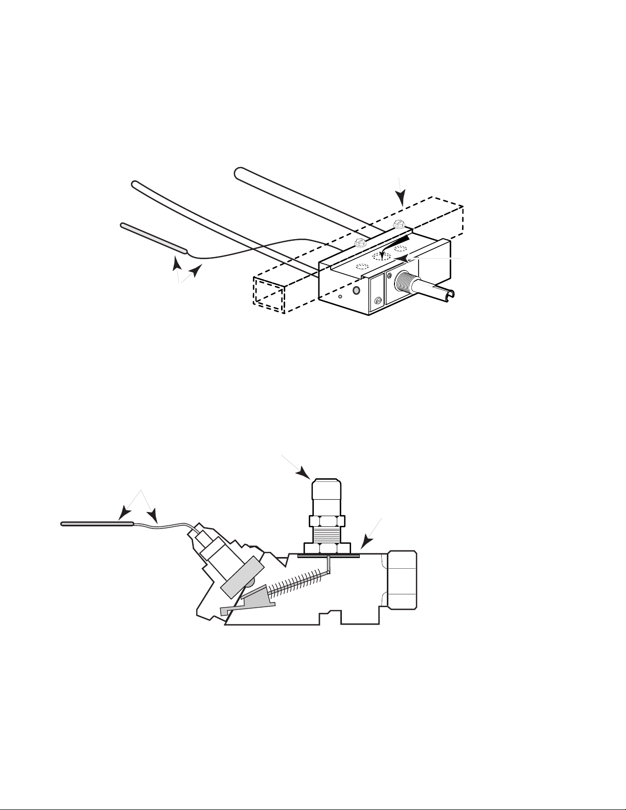
The
Thermostat
Figure 4-2 ). The
gas to the oven safety valve. The
is a hydraulic valve that has two separate gas lines and a sensing bulb (see
pilot
gas line maintains a pilot flame in the oven, and the
sensing bulb
is a mercury-filled tube that controls the thermostat
main
gas line provides
to open or close the gas lines, and release gas from the manifold pipe to the oven safety valve. The
thermostat operates based on the temperature it senses in the oven cavity.
Manifold
Main Gas Line
Pilot Gas Line
Gas In
T
OFF
A
N
Sensing Bulb &
Capillary Tube
Figure 4-2
P
L
Thermostat
Oven
The
Oven Safety Valve
is also a hydraulic valve that has a gas inlet line and a gas port that is
metered by an orifice hood (see Figure 4-3). It also has a mercury-filled sensing bulb that controls
its operation. The safety valve has one function: to release gas to the oven burner from the
thermostat.
Orifice Hood
Heater Sensing
Bulb & Capillary Tube
Valve Closed
No Gas Flow
Cold Sensor
Gas Inlet
(From Thermostat)
Safety Valve
Figure 4-3
Page 4-2
Page 47
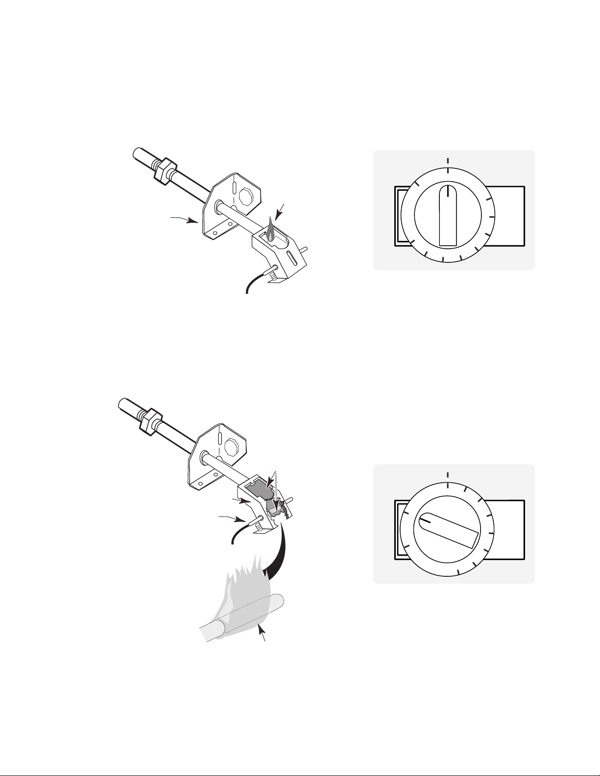
The interaction between the thermostat and the safety valve is very important and critical to the
operation of the oven. The thermostat provides two separate functions each time it is turned on,
but first, we need to know what the thermostat does when it is in the “OFF” position. Even with the
thermostat in the “Off” position, a supply of gas from the manifold pipe is always available through
the thermostat to the oven pilot assembly. It supplies enough gas to maintain a constant or
“standing” pilot flame in the oven at all times (see Figure 4-4).
Standing Pilot
Assembly
Standing
Pilot Flame
P
L
OFF
BROIL
T
A
N
550
500
OFF
450
200
250
300
350
400
The Standing Pilot
Figure 4-4
Thermostat Off
When the thermostat is turned “ON” to any temperature, its primary function is to increase the flow
of gas to the oven pilot assembly so that the “standing” pilot flame enlarges to create a “larger
standing pilot” or a “
heater pilot flame
.” This larger flame is deflected by a
flame spreader
(see
Figure 4-5) to heat the sensing bulb from the safety valve and hydraulically open it.
Heater Pilot
Flame Spreads
Down To Sensing Bulb
Flame Spreader
Safety Valve
Sensing Bulb
Heater Pilot
Flame Wraps
Around Sensor
Page 4-3
P
L
Figure 4-5
200
250
300
OFF
OFF
T
A
N
BROIL
350
400
450
500
550
The Standing Pilot
Thermostat On
Page 48
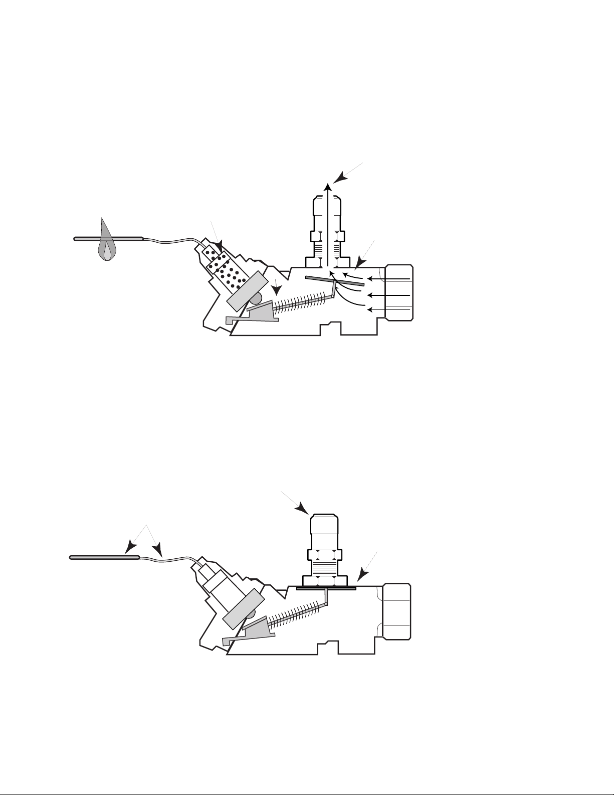
As this is taking place, the thermostat also opens the main gas line, and provides gas to the safety
y
Orifice Hood
Heater Sensing
Bulb & Capillary Tube
Gas Inlet
(From Thermostat)
Cold Sensor
Valve Closed
No Gas Flow
Safety Valve
valve (see Figure 4-6). As soon as the safety valve is hydraulically opened by the signal from the
sensing bulb, gas is released from the safety valve to the oven burner, and ignited by the heater
pilot flame. NOTE: If the heater pilot flame is not available to heat the safety valve sensing bulb,
the safety valve will not open, and gas can not enter the oven.
Gas Flows Out
Pressure Forces
Orifice Hood
Contact Against
Switch & Opens Valve
Valve Opens & Gas
Flows To Oven Burner
Heater Flame
Heats Sensor
Gas Inlet
(From Thermostat)
Gas Safety Valve Open
Safet
When the oven reaches the selected temperature, the sensing bulb for the thermostat closes the
thermostat gas lines and reduces the heater pilot flame back to a smaller “standing pilot” flame.
With no heater pilot flame, the sensing bulb for the safety valve cools, closes the safety valve, (see
Figure 4-7), stops the gas supply to the oven burner, and eliminates the flame. This cycling will
continue for the duration of the cooking cycle.
Valve
Figure 4-6
Gas Safety Valve Closed
Figure 4-7
Page 4-4
Page 49
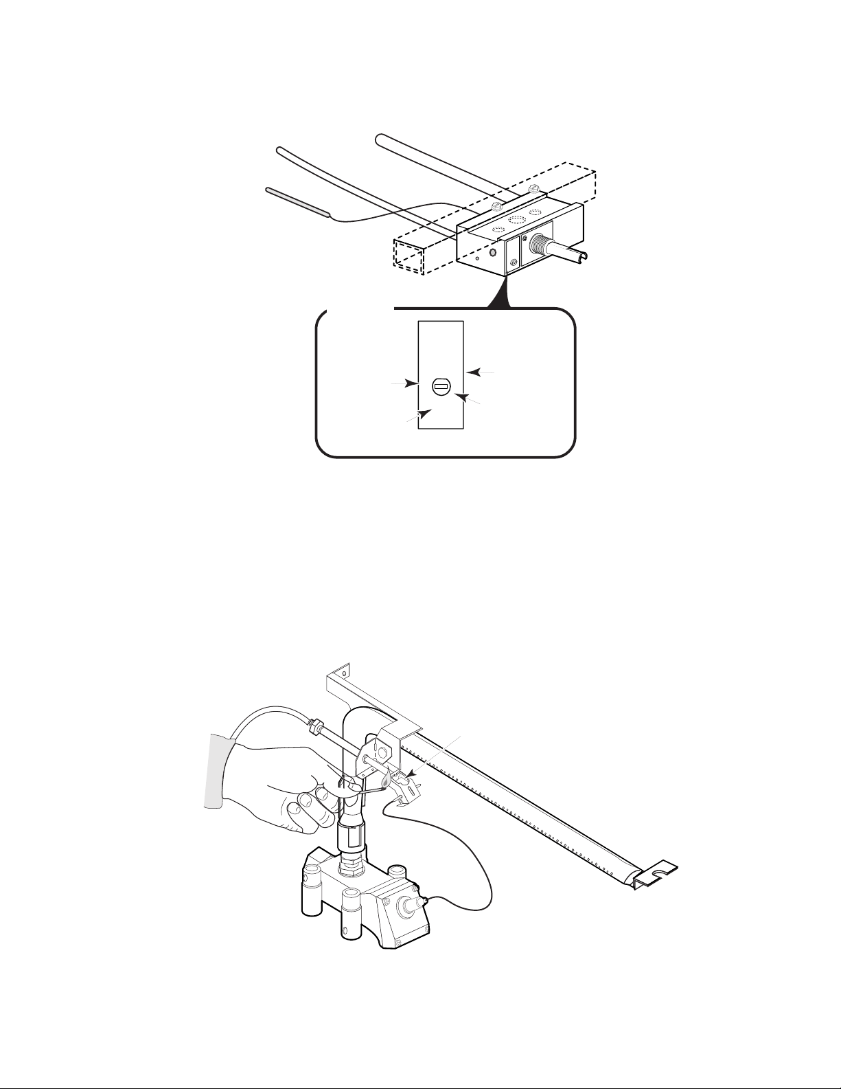
NOTE: The thermostat used in the Standing Pilot range needs to be converted if L.P. gas is being
used. A "Nat" or “L.P.” setting is located on the front face of the thermostat (see Figure 4-8 and its
inset).
Main Gas Line
Pilot Gas Line
T
OFF
A
N
P
L
Oven
Thermostat
Inset
L.P. Gas
Setting
Gas “OFF”
Setting
N
L
P
OFF
A
T
Adjustment
Natural Gas
Setting
Figure 4-8
Screw
LIGHTING THE OVEN PILOT
To light the pilot, perform the following steps (see Figure 4-9):
1. Turn off all the range controls.
2. If your range is equipped with a broiler drawer, open it and wait five minutes for any gas inside
the range to dissipate.
3. Remove the baffle and oven bottom.
4. Hold a lighted match near the tip of the pilot on the burner assembly until a flame appears.
Apply Match Flame
To Gas Outlet Of Pilot
Safety
Valve
5. Replace the baffle and oven bottom.
6. Turn on the oven thermostat and allow the burner to light.
Page 4-5
Figure 4-9
Page 50
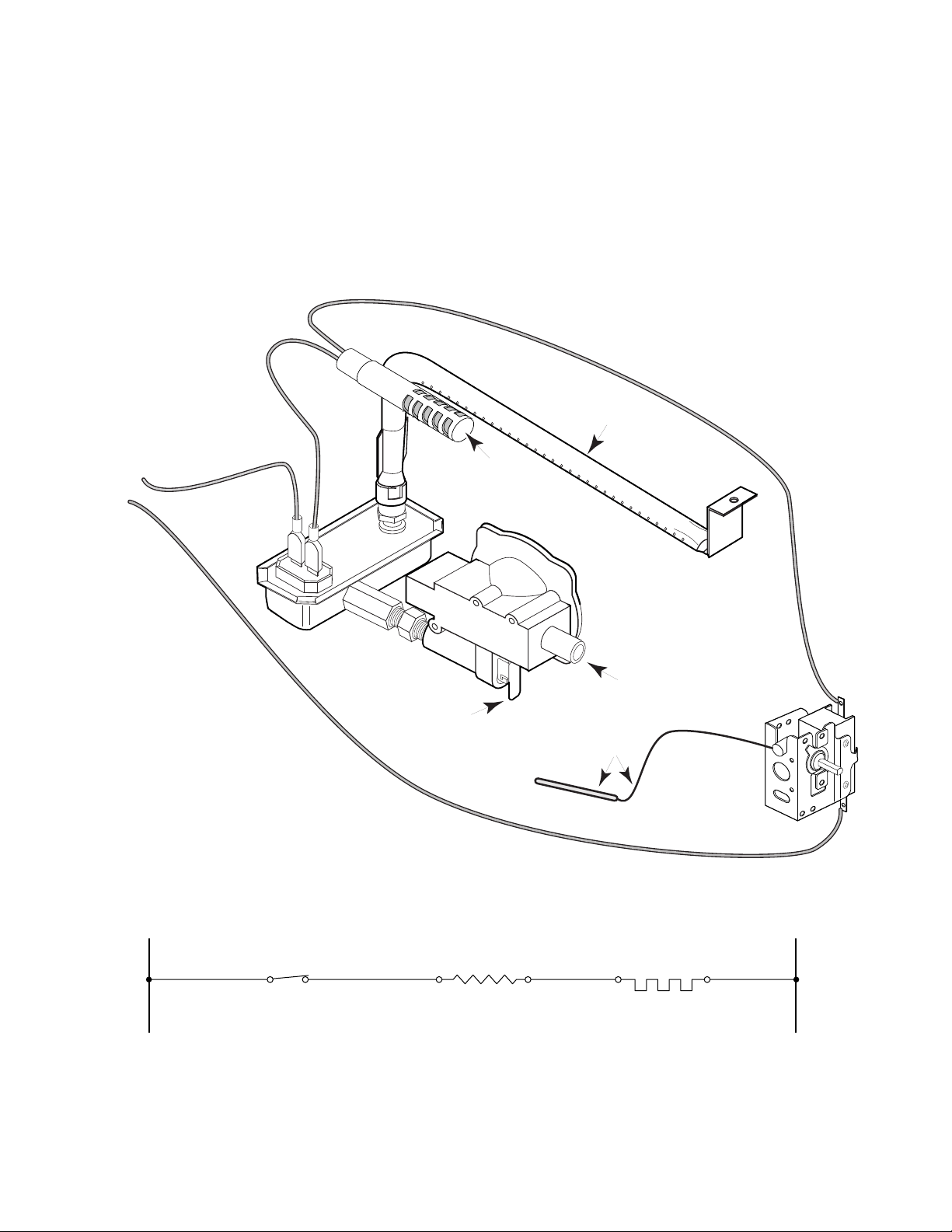
GLO-BAR IGNITION
The
Glo-Bar Ignition System
three important components. The three components, a thermostat that is controlled by the
customer, an ignitor and a safety valve, both located inside the oven, create a very efficient system
that is safe and dependable. Unlike the mechanical system that works with a sensor and capillary
tube to operate the safety valve, this system operates entirely on an electrical system requiring 120volts AC (alternating current).
(see Figure 4-10) is a 120-volt electrical system that consists of
Oven
Burner
120-Volt
Supply
Safety
Valve
Glo-Bar
Ignitor
Manual
Gas Shutoff
Valve
Pressure
Regulator
Main Gas
Inlet
Sensing Bulb &
Capillary Tube
Oven
Thermostat
Thermostat
Switch Contacts
Oven Ignitor
Figure 4-10
Page 4-6
NL1
Safety Valve
Page 51
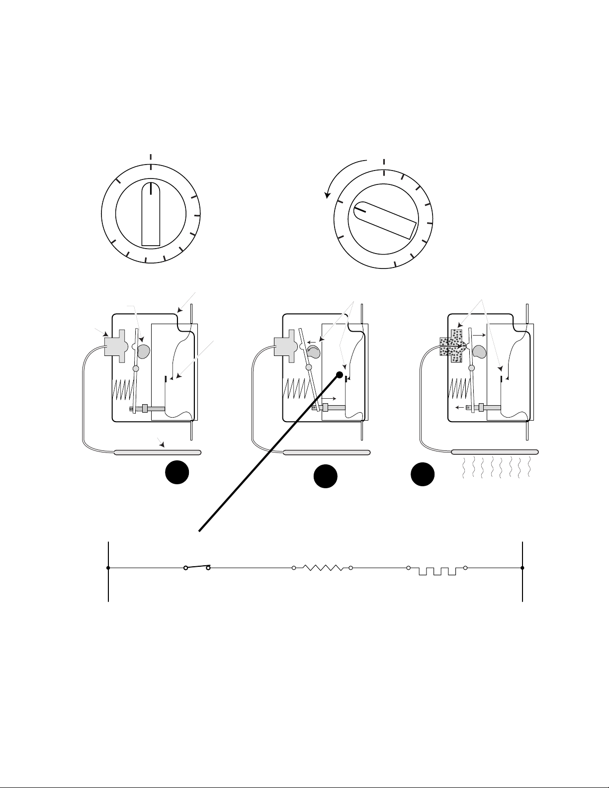
The
Thermostat
contains a set of contacts that open and close, (see Figure 4-11A), depending
on the temperature selected by the customer, and the temperature monitored in the oven cavity.
When the thermostat is turned to the “ON” position, contacts within the thermostat close to
complete an electrical circuit (see Figure 4-11B). As the oven heats up to a selected temperature,
the internal pressure within the sensing bulb increases until the thermostat contacts are forced
open (see Figure 4-11C).
Sensor
Actuator
OFF
BROIL
550
500
1. Oven Off
Switch Open
Shaft
Sensing Bulb
450
350
400
200
250
300
Oven
Thermostat
Switch
Contacts
200
OFF
BROIL
2. Oven On
Shaft Rotates Against
Actuator - Switch Closes
250
300
350
400
450
500
550
3. Oven Temp Reached
Pressure Expands Sensor Actuator
& Pushes Against Switch Actuator
- Switch Opens - Oven Turns Off
A
B
C
200˚ Heat From Oven
Figure 4-11
Thermostat
Switch Contacts
Oven Ignitor
Safety Valve
NL1
Figure 4-12
As the oven cools, the pressure from the sensor actuator decreases, and the thermostat contacts
close. This cycling of the contacts opening & closing continues until the cooking function is
complete. The electrical contacts of the thermostat complete an electrical circuit through the ignitor
and safety valve to the neutral side of the 120-volt circuit (see Figure 4-12).
Page 4-7
Page 52
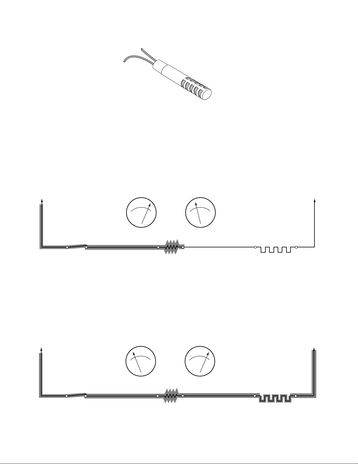
The
Oven Ignitor
is made of a silicon-carbide material (see Figure 4-13).
Oven Glo-Bar
Ignitor
Figure 4-13
When voltage is applied to the ignitor, it heats up to 2000˚F. As its temperature increases, its
resistance decreases, allowing 2.5 to 3.0 amps to flow to the bimetal in the safety valve. This
measurement is critical to the proper operation of the ignitor. In many cases, the ignitor can glow
red, but not provide the proper amperage to the safety valve. At a room temperature of 75˚F, the
resistance of the ignitor should be between 50 and 1100 Ω. At room temperature the ignitor can
not provide enough amperage to properly operate the safety valve (see Figure 4-14).
Amperage = voltage divided by resistance (cold ignitor)
Amperage = 120 volts ÷ 500 ohms
Amperage = .24
Thermostat
Switch Contacts
50 to 1100 Ω
Oven Ignitor
.24 AMPS
NL1
Safety Valve
Bimetal
Figure 4-14
As the ignitor heats toward 2000˚F, its resistance drops to approximately 40 to 45 Ω, and can then
operate the safety valve (see Figure 4-15).
Amperage = voltage divided by resistance (hot ignitor)
Amperage = 120 volts ÷ 40 ohms
Amperage = 3.0
50 to 1100 Ω
2.5 to 3.0 AMPS
NL1
Thermostat
Switch Contacts
Oven Ignitor
Figure 4-15
Page 4-8
Safety Valve
Bimetal
Page 53
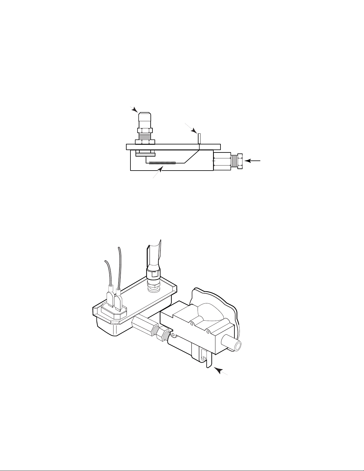
The oven uses a
inlet and one gas outlet, for the combination Bake and Broil burner. The safety valve uses an
electrically-operated device at the gas outlet to control the gas flow to the oven burner. The device
consists of an electric heater coil wrapped around a bimetal strip. One end of the bimetal is riveted
to the plate of the valve. The other end has a rubber seat attached to it that covers the gas outlet.
At room temperature, the spring force of the bimetal presses the rubber seat against the gas outlet.
Single Safety Valve
Gas Outlet
(To Oven Burner)
that is bimetal-operated (see Figure 4-16). It has one gas
120 Volt
Supply Terminal
Safety Valve
Bimetal & Heater Coil
No Current Flow -
Valve Is Closed
Gas is available at the safety valve at all times, but can be shut off by a manual shutoff valve on
the regulator (see Figure 4-17).
Figure 4-16
Gas Inlet
(From Regulator)
Pressure
Regulator
Safety
Valve
Figure 4-17
Manual Gas
Shutoff Valve
Page 4-9
Page 54
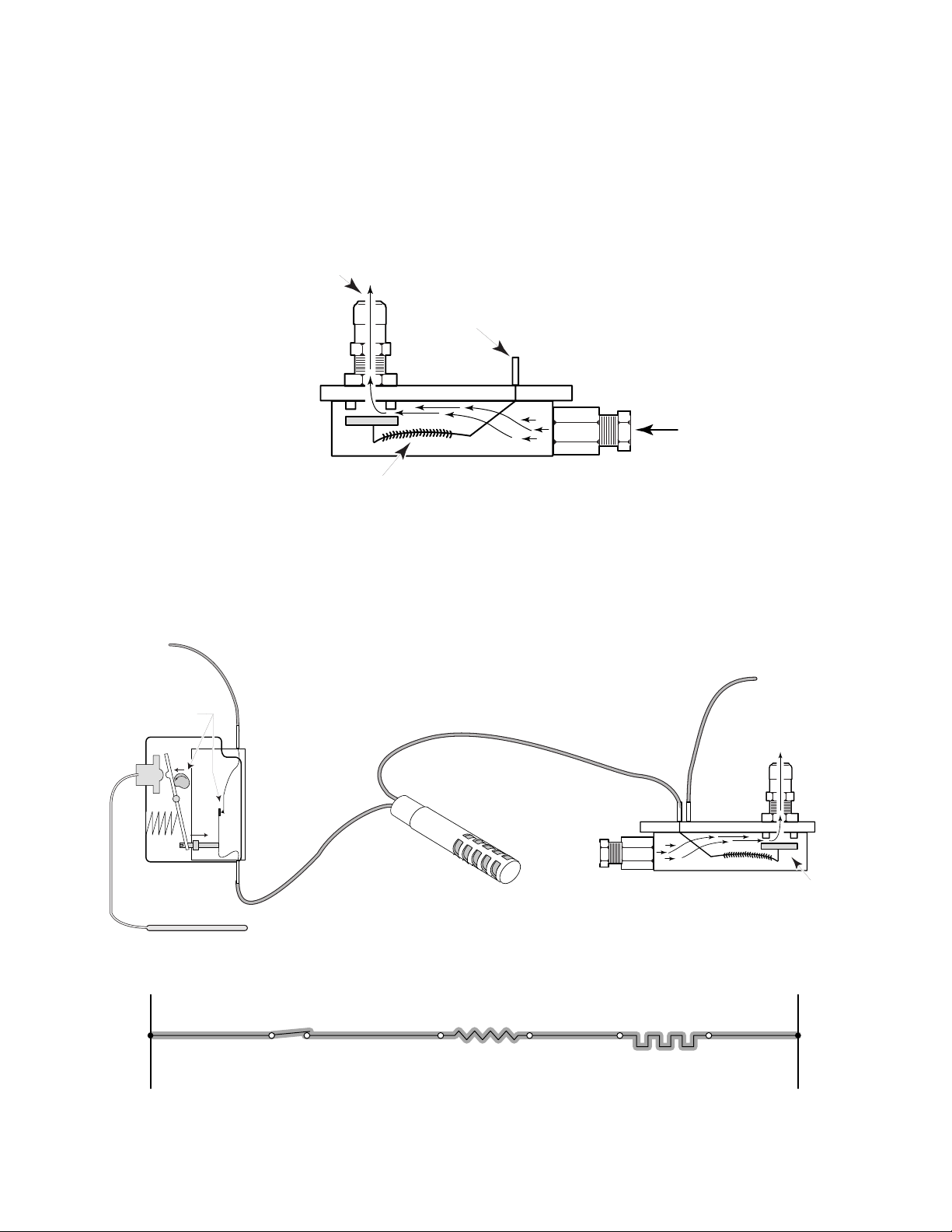
p
When current flows through the ignitor, heat is applied to the bimetal strip. The amount of heat
necessary to warp the bimetal enough to open the valve requires 3.0 amps of current flow in the
circuit (see Figure 4-18). The reason the valve is designed not to open below 3.0 amps, is to insure
that the temperature of the oven ignitor is above 1800˚F before the valve opens. The operation of
the system is complete when gas is flowing from the safety valve to the oven burner, and is ignited
with the hot glo-bar ignitor. The entire process may take between 40 to 60 seconds to start.
Gas Outlet
(To Oven Burner)
120 Volt
Supply Terminal
Safety Valve
Gas Inlet
(From Regulator)
Current Warps Bimetal
& Valve O
ens
Figure 4-18
Throughout the cooking cycle, the oven will continue to “heat up” and “cool down” to maintain the
selected temperature (see Figure 4-19). This operation is controlled by the thermostat’s sensing
bulb.
L1
Thermostat Switch
Contacts Closed
Oven Is Heating
Oven Glo-Bar
Ignitor
N
To Oven Burner
Thermostat
Switch Contacts
3.0 Amps
Oven Ignitor
Figure 4-19
Page 4-10
Safety Valve
Safety Valve
Safety Valve Opens
& Gas Flows
To Oven Burner
NL1
Page 55
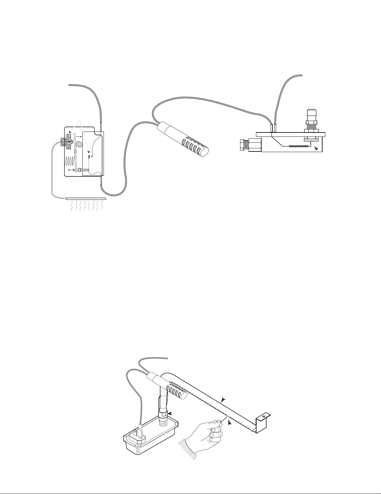
When the thermostat senses that the selected oven temperature is reached, its internal contacts
open, as discussed earlier, and the electrical circuit is terminated (see Figure 4-20). The bimetal
cools and closes the safety valve to shut off the gas flow to the oven burner. This cycling of the
electrical system continues throughout the cooking cycle.
N
L1
Thermostat Switch
Contacts Open
Oven Is Cooling
To Oven Burner
Oven Glo-Bar
Ignitor
Low Amperage
Safety Valve
Safety Valve Closed
No Gas Flow
To Oven Burner
Figure 4-20
200˚ Heat From Oven
CLEANING THE OVEN BURNER
The most common burner maIfunction is clogging due to excess dirt and debris, which can enter
the burner through the burner ports. This excess dirt can block one or several of the ports so that
the burner will have trouble lighting, or will not light at all. In this case, the burner ports must be
cleared using a pin (see Figure 4-21).
The air shutter is an additional inlet where dust can enter a main burner. Whether or not the burner
is operating, dust can still be drawn into the burner through the air shutter. The debris can clog the
venturi, orifice, mixing tube, or burner ports. Again, this type of clogging can reduce, if not stop, the
flow of gas through the burner. In addition, the primary air shutter itself can become blocked,
restricting the flow of primary air into the burner.
In any event, cleaning the burner normally eliminates most of the dirt buildup. Also, it is a good
practice to keep the area immediately surrounding the main burner as clean as possible to reduce
the possibility of clogging any part of the main burner.
Oven
Burner
Air Shutter
Pin
Figure 4-21
Page 4-11
Page 56
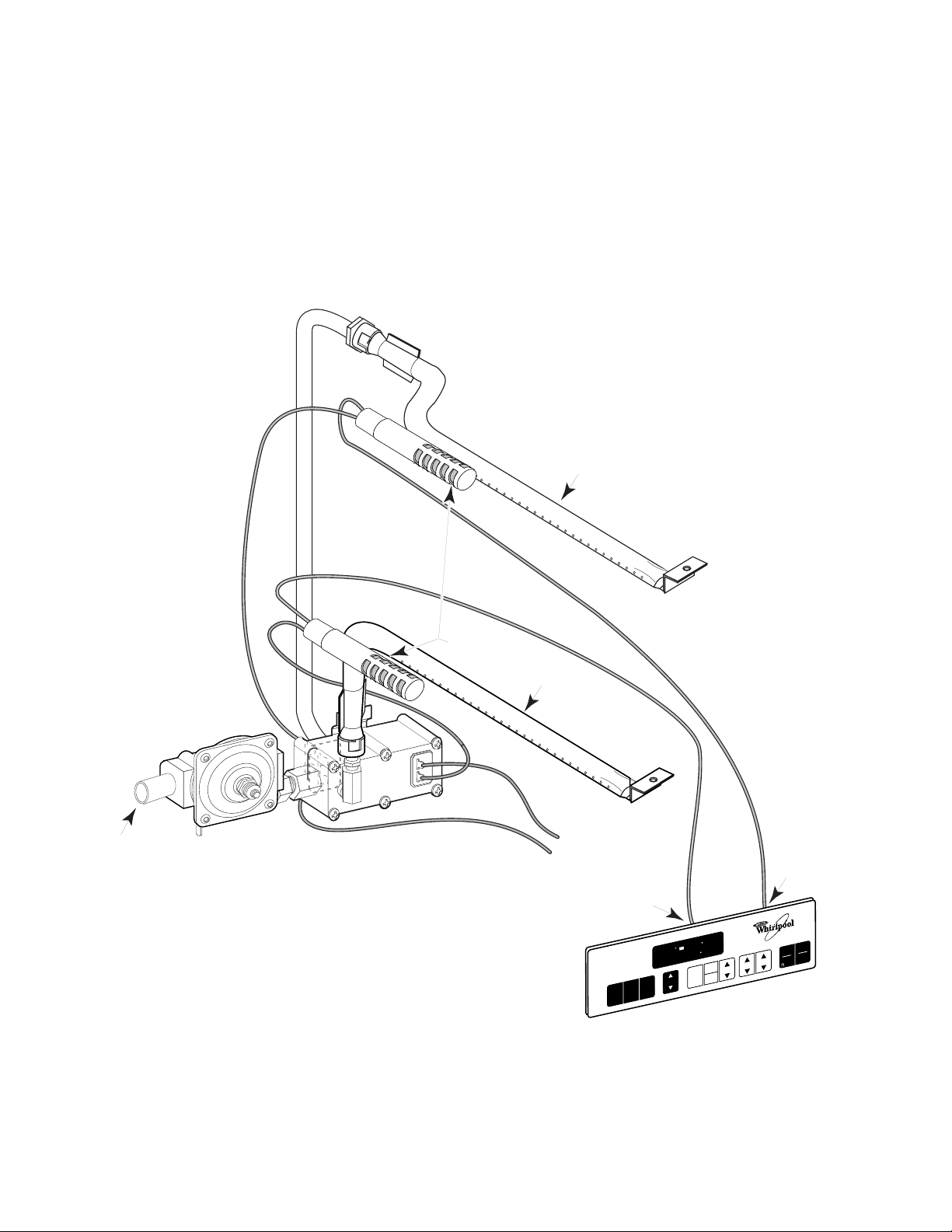
SELF-CLEANING SYSTEM
All Whirlpool Self-Cleaning Gas ranges use two burners in the oven to provide even heating during the
Bake and Broil functions, and higher temperature during the Self-Clean cycle (see Figure 4-22). To
provide each of these features, the system incorporates a
Glo-Bar Ignition System already discussed, plus an additional
bake burner
broil burner
benefit of broiling inside the same oven cavity. All Self-Clean ranges feature electronic controls,
which utilize an accurate and responsive electronic sensor.
Broil Gas
Line
Broil Burner
that operates just like the
that provides the
Main Gas
Inlet
Pressure
Regulator
Dual Safety Valve
Figure 4-22
Glo-Bar
Ignitors
Bake Burner
120-Volt
Supply
Bake Relay
Wires To
SELF-CLEANING OVEN
CUSTOM
BROIL
BAKE
N
O
P
M
TE
N
A
LE
88 88
C
D
K
C
888
IL LO
O
R
B
E
K
A
T B
A
E
H
AUTO
CLEAN
TIMER
SET
CLOCK
TIMER
OFF
TEMP
Oven Control Panel
(Thermostat)
MIN
Broil Relay
MIN
HR
Wires To
OFF
START
CANCEL
ENTER
5 SEC
Page 4-12
Page 57
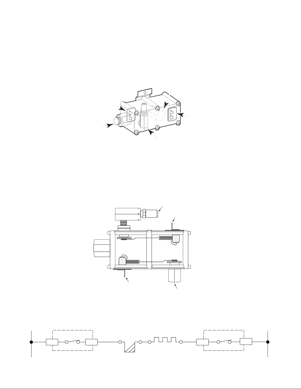
Self-Clean ovens use a dual safety valve that is bimetal-operated. The dual valve has one gas inlet
and two gas outlets; one for the Bake burner and the other for the Broil burner (see Figure 4-23).
It uses two identical electrically-operated devices, one for each outlet, to control thc gas flow. The
devices consist of an electric heater coil wrapped around a bimetal strip. One end of the bimetal
is riveted to the plate of the valve. The other end has a rubber seat attached to it that covers a gas
outlet. At room temperature, the spring force of the bimetal presses the rubber seat against the gas
outlet.
Broil Burner
Gas Outlet
Broil Bimetal
Terminals
Bake Bimetal
Terminals
Main Gas Inlet
Dual
Safety Valve
Bake Burner
Gas Outlet
Figure 4-23
When current flows through the ignitor, heat is applied to the bimetal strip. The amount of heat
necessary to warp the bimetal enough to open the valve requires 3.0 amps of current flow in the
circuit (see Figure 4-24). The reason the valve is designed not to open below 3.0 amps, is to insure
that the temperature of the oven ignitor is above 1800˚F before the valve opens.
To prevent miswiring, the Bake terminals and Broil terminals are sized differently.
Gas Outlet
To Bake Burner
Bake Terminals
Bake
Gas Valve
Bimetal
Coil
Bimetal
Coil
Broil
Gas Valve
Figure 4-24
Broil Terminals
Gas Outlet
To Broil Burner
The electrical circuit is initiated by relays on the electronic control board. The electrical circuit is
similiar to the circuit used with the Glo-Bar Ignition System (see Figure 4-25).
L1 N
BK
OVEN CONTROL
BROIL RELAY
P3-4P3-1
R
BAKE IGNITOR
BAKE VALVE
WW
OVEN CONTROL
BAKE RELAY
P2-4
P2-1
Figure 4-25
Page 4-13
Page 58
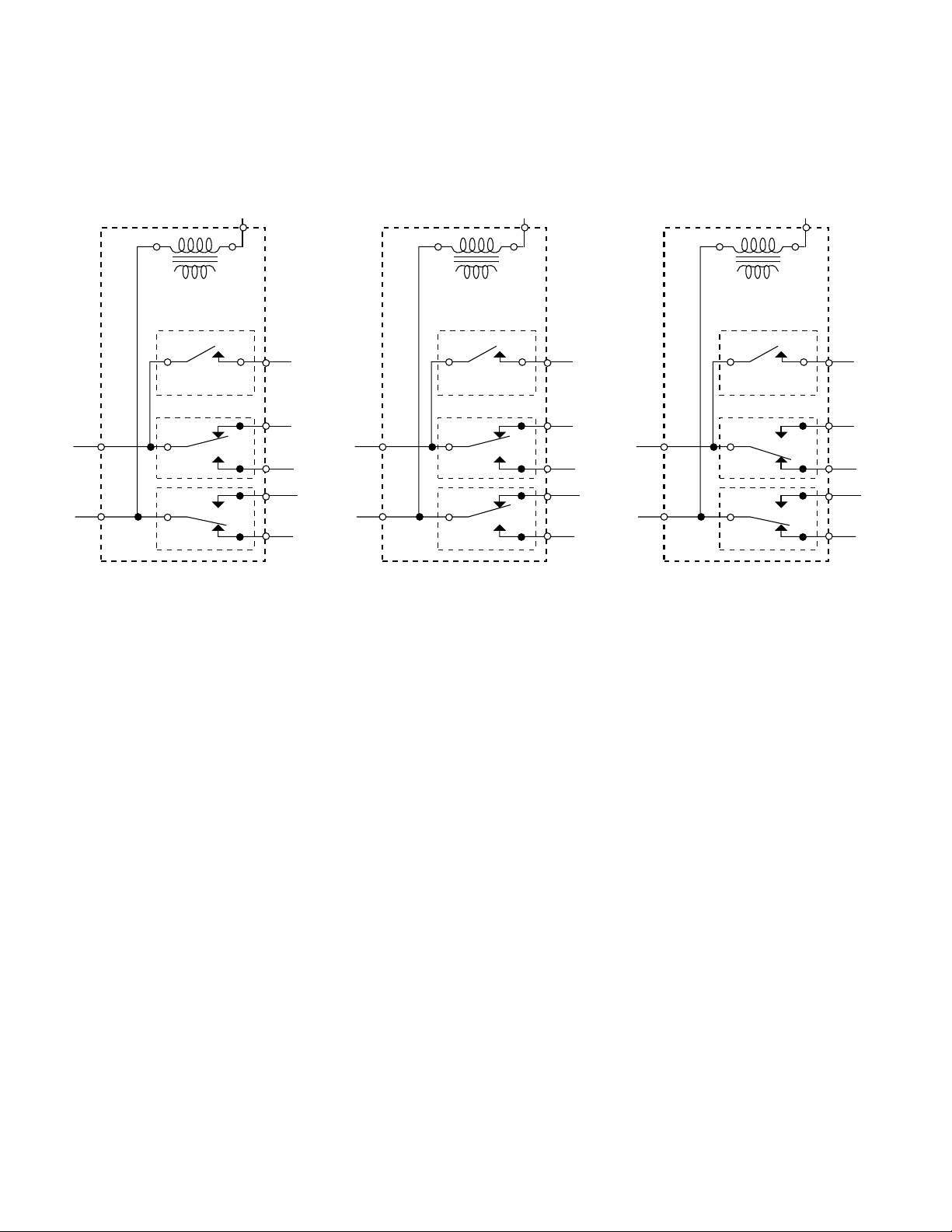
The electronic board is constructed with individual relays to operate the Bake, Broil, and Self Clean
functions independently of each other. The Microcomputer board electrical diagrams (see Figure
4-26) show how opening and closing the relays operate the various customer-selected cycles.
OVEN CONTROL
TRANSFORMER
LATCH SOLENOID
P3-1
BROIL
RELAY
P2-1
BAKE
RELAY
Oven Off Bake Cycle Broil Cycle
RELAY
OVEN CONTROL
P5
TRANSFORMER
P4
LATCH SOLENOID
RELAY
P3-4
P3-1
P3-2
P2-4
P2-1
P2-2
BROIL
RELAY
BAKE
RELAY
P5
P4
P3-4
P3-2
P2-4
P2-2
OVEN CONTROL
TRANSFORMER
LATCH SOLENOID
P3-1
BROIL
RELAY
P2-1
BAKE
RELAY
P5
P4
RELAY
P3-4
P3-2
P2-4
P2-2
Figure 4-26
Page 4-14
Page 59
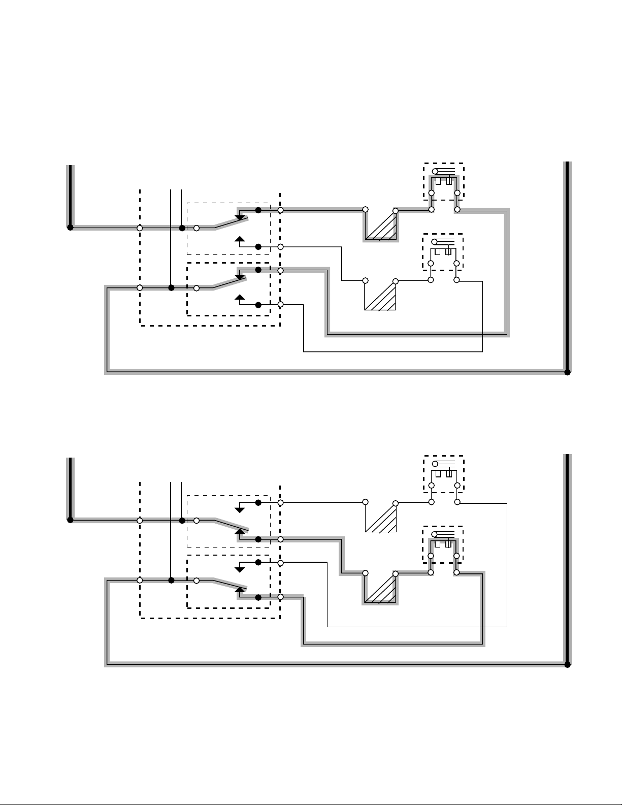
By the construction of the relays, both the Bake Function (see Figure 4-27), and the Broil function
(see Figure 4-28), can not operate at the same time. The normally-closed position of the opposite
relay is needed to complete the circuit.
BAKE
NL1
BROIL
P3-1
P2-1
P3-1
P2-1
BROIL
RELAY
BAKE
RELAY
BROIL
RELAY
BAKE
RELAY
N.C.
N.C.
N.C.
N.C.
P3-4
P3-2
P2-4
P2-2
RR
BU
W
W
Figure 4-27
P3-4
P3-2
P2-4
P2-2
RR
BU
W
BAKE VALVE
BAKE IGNITOR
BU
BROIL VALVE
BROIL IGNITOR
NL1
BAKE VALVE
BAKE IGNITOR
BU
BROIL VALVE
BROIL IGNITOR
W
Figure 4-28
Page 4-15
Page 60

F-CODE GUIDELINES
F0 = If the most recent F-code is recalled via user input, F0 indicates no failure has occurred.
F1 = Electronics Subsystem Failure.
Replace electronic control board.
E0 = EEPROM communication error.
E1 = EEPROM checksum error.
E2 = A/D converter error (is there an error bit in the micro?; does this mean lost a voltage
rail?).
E5 = Calibration shifted.
E9 = Stack overflow.
F2 = Keypad Subsystem Failure. Replace keypad if properly connected and this F-code is
displayed.
E0 = Shorted key / key stuck.
E1 = Keypad / keytail not connected.
E5 = Cancel key low or open.
F3 = Cavity Temperature Sensor Failure.
Check for welded relays; if OK then replace temperature sensor.
E0 = Sensor open.
E1 = Sensor shorted.
E2 = Non-self-clean over temperature (usually 550˚F).
E3 = Self-clean over temperature (usually 900˚F).
F5 = Latch Subsystem Failure.
Check for proper latch movement; check for proper switch actuation; check for proper
clearance between latch and door.
E0 = Latch switch does not agree with door switch (i.e. Iatch in locked position with door
open).
E1 = Latch will not lock.
E5 = Self-clean temperature set point not reached within required time range (usually
30 to 45 minutes).
E7 = Latch will not unlock.
NOTE: Never lock the door in association with an F-code. The door should only lock at high
temperatures (usually above 550˚F) or while in Self Clean. The door should unlock immediately
when the cavity falls below the unsafe temperature.
Page 4-16
Page 61

PERFORMANCE CHECK
1. Remove the oven’s operating system (burners, safety valves, and ignitors).
Page 4-17
Page 62
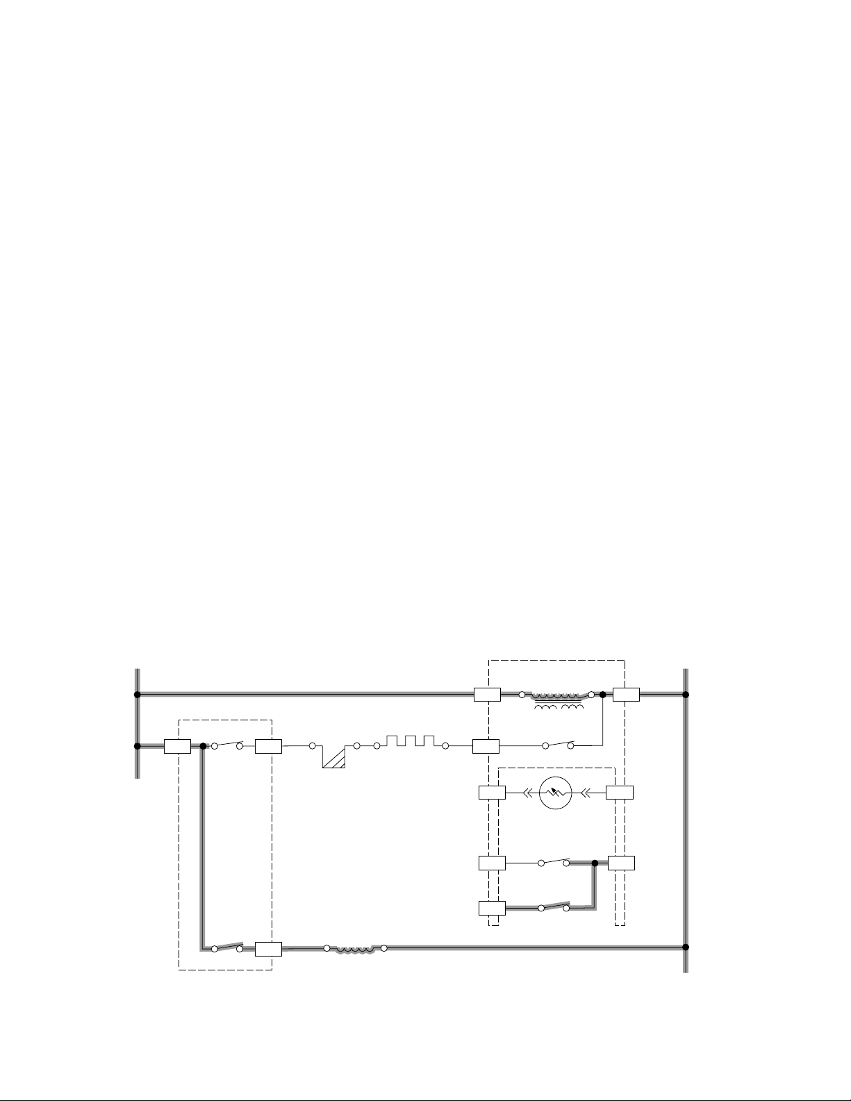
THE SELF-CLEAN OVEN DOOR LOCKING SYSTEM
At any time a range is in a self-clean operation, it needs to provide a safe environment for the
customer. A self-clean cycle will reach temperatures of over 800˚F during its 2- to 4-hour cycle. To
prevent the consumer from accessing the oven while these extreme temperatures are present,
every self-clean range is equipped with an oven door lock system. This system locks the oven door
whenever the oven cavity temperature exceeds 600˚F. The system can be activated by the
consumer manually, using a lock lever, or electrically. Whirlpool ranges utilize an electronic locking
system to assure that the range will not operate unless the oven door is safely locked during high
temperatures.
The electronic system consists of:
• An electronic control.
• A door latch switch.
• A door latch solenoid.
• A door latch switch to provide feedback to the microcomputer board.
• A door latch. NOTE: The oven sensor is also a critical component of the system because
it monitors temperatures needed to control the system.
The Self-Clean System begins at the control board (see Figure 4-29). As the CLEAN function is
programmed into the control and the START pad is pushed, the latch relay on the microcomputer
board closes for less then a second. This allows just enough time to provide a 110 volt pulse to the
solenoid.
The solenoid is a spring-loaded “push-push” mechanism. As voltage is applied, the solenoid
pushes against the spring-loaded plunger, and extends it. This operation only requires a pulse of
electricity. As the plunger is extended, the next pulse of electricity will again push against the spring
loaded plunger, and retract it. This “push-push” function can be related to the extension and
retraction of a fountain pen.
L1 N
P5 P2-1
OVEN CONTROL
BAKE VALVE
W
W
P2-4
P1-6
P1-3
P3-1
BROIL RELAY
LATCH RELAY*
(N.O.)
P3-4
P4
BK
BU
BR
BAKE IGNITOR
LATCH
SOLENOID
OVEN CONTROL
TRANSFORMER
BAKE RELAY
VV
P1-7
SENSOR
DOOR LATCH
SWITCH
SWITCH
GY
P1-5P1-1
GY
Y
DOOR LATCH
BU
WBK
* PULSE 1 SECOND
Figure 4-29
Page 4-18
Page 63
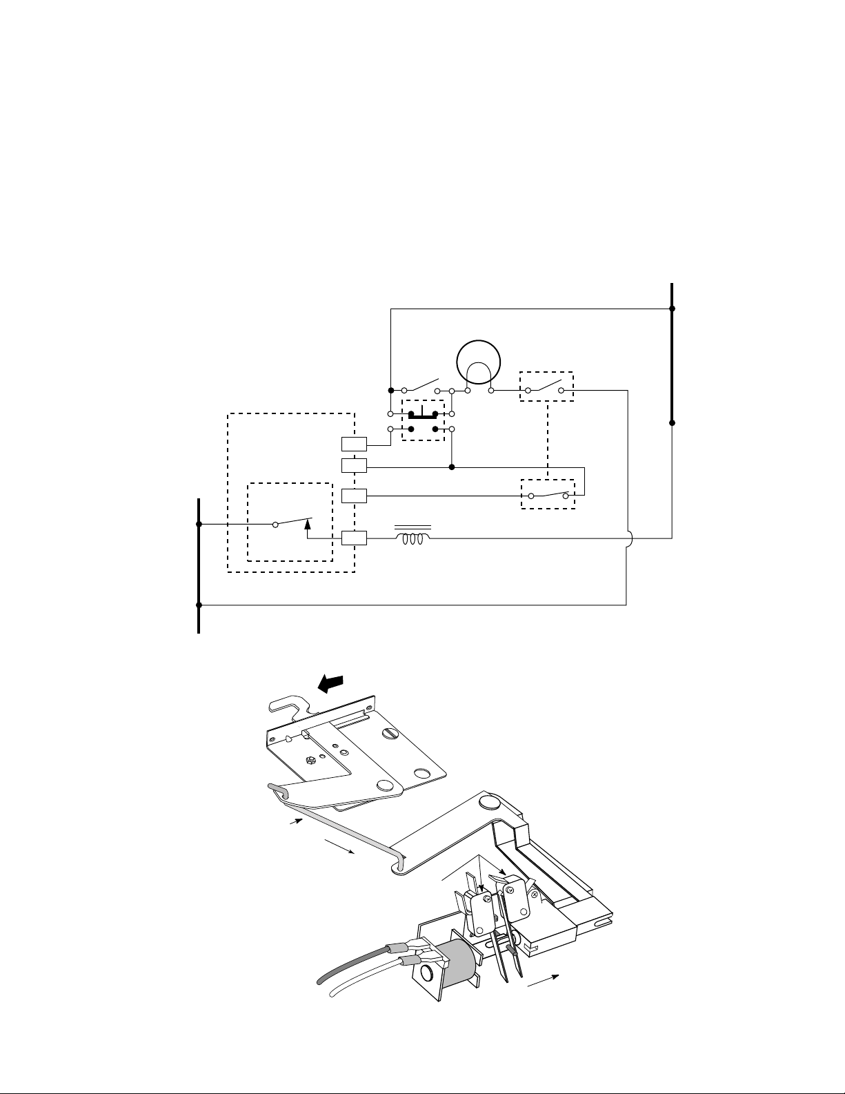
When the solenoid plunger extends, two things happen (see Figure 4-30). As the latch solenoid
locks the door, it also activates the two door latch switches. Both door switches are normally-open
switches. As the solenoid moves to lock the door, the switches toggle, and:
a) Open the oven light circuit so that the light cannot be operated during the Clean function.
b) Provide a logic circuit for the electronic board to indicate that the door is locked and that
the Clean cycle can continue.
N
OVEN LIGHT
DOOR LATCH
BK
SWITCH
R
N.O.
W
OVEN CONTROL
W
MANUAL
OVEN LIGHT
SWITCH
W
W
L1
BK
Actuator Rod
LATCH SOLENOID
RELAY
1 SEC PULSE
DOOR LOCKED
P1-1
P1-5
P1-3
P4
Y
DOOR
LIGHT SW.
BU
LATCH
SOLENOID
Y
GY
DOOR LATCH
SWITCH
N.O.
Figure 4-30
Door Latch
Switches
Page 4-19
Solenoid Plunger
Extended
Page 64
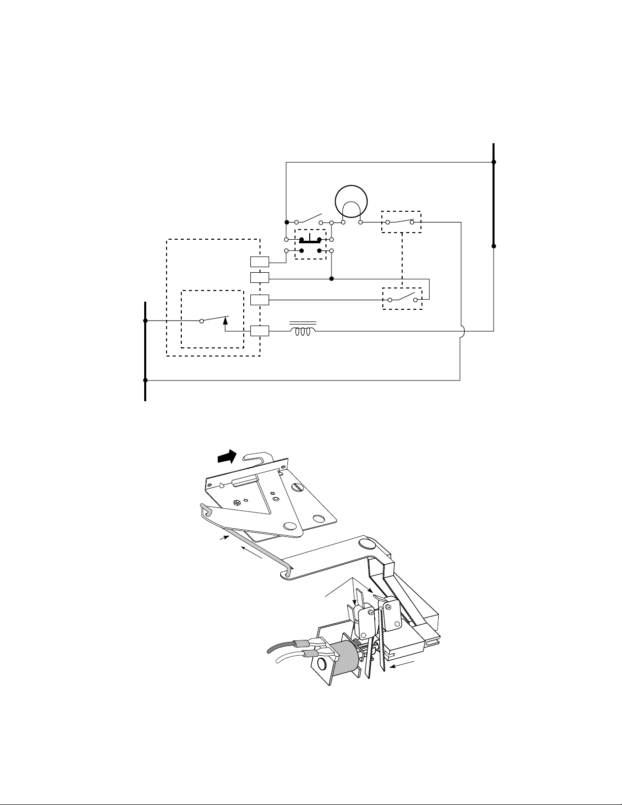
When the oven temperature reaches 600˚, the oven door cannot be opened until the oven cools
down to below 550˚. At that point, the latch solenoid relay will close for just a second, and provide
a 120 VAC pulse to the latch solenoid (see Figure 4-31). This unlocks the door and toggles the door
latch switches to their normal state.
N
OVEN LIGHT
OVEN CONTROL
W
MANUAL
OVEN LIGHT
SWITCH
W
W
DOOR LATCH
BK
SWITCH
R
N.O.
W
L1
BK
LATCH SOLENOID
RELAY
1 SEC PULSE
DOOR UNLOCKED
Actuator Rod
P1-1
P1-5
P1-3
P4
Y
DOOR
LIGHT SW.
BU
LATCH
SOLENOID
Y
GY
N.O.
DOOR LATCH
SWITCH
Figure 4-31
Door Latch
Switches
Page 4-20
Solenoid Plunger
Retracted
Page 65

NATURAL AND L.P. GAS CONVERSION
GENERAL
Ranges must be adjusted when going from one type of fuel to another due to the characteristics
of the gases. This means that, for efficient combustion, air must be mixed with the gas. The amount
of air to be mixed with the amount of gas is called the
air-to-gas ratio
different between natural and L.P. gas. L.P. gas requires much more air (24:1) to be mixed with
it than natural gas (10:1).
. The combustion ratio is
Also, there are differences in
caloric values
between the gasses. When a cubic foot of L.P. gas
is burned, it produces much more heat than the same volume of natural gas. This is why the burner
orifices must be changed to restrict the gas flow when converting to L.P. use. In other words, the
range uses less fuel and more air with L.P. gas to create the same amount of heat with natural gas.
L.P. gas is also distributed and used at higher pressure (11" WCP) than natural gas (4" WCP). This
is why the pressure regulator must be converted when changing from natural gas to L.P. operation
(refer to the following chart).
NATURAL PROPANE BUTANE
CHARACTERISTICS
Colorless, Odorless, Non-Toxic, Gaseous
B.T.U./Cu. Ft. 900 to 1100 2500 3010
Combustion Ratio Cu.
Ft. Air/Cu. Ft. Gas
Operating Pressures:
Manual
Service
Range
10 24 31
8.25 PSI
5" - 14" WCP
4" WCP
(Oxidizer Added)
Not Applicable
11" - 15" WCP
10" WCP
Not Applicable
11" - 15" WCP
10" WCP
GAS CHARACTERISTICS
Change Regulator Orifices & Air Shutters Due To Differences In Gasses
COOKTOP
RANGE TYPE REGULATOR
NON SELF-CLEAN X X 1 X X
SELF-CLEAN X X 2 X
COOKTOPS WITH
CONVENTIONAL
BURNERS
COOKTOPS WITH
SEALED
BURNERS
XX X
XX
BURNER
SPUDS
OVEN
BURNERS
THERMOSTAT
AIR
ADJUST
Page 5-1
Page 66
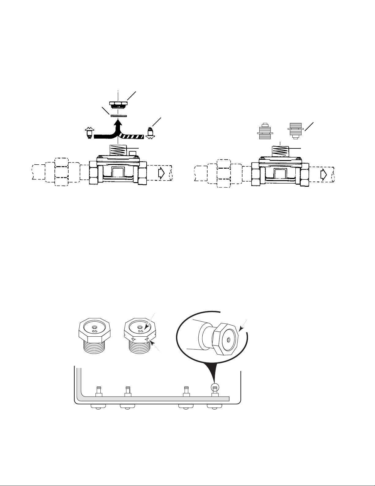
CONVERTING A PRESSURE REGULATOR
By varying the tension of the regulator spring, the gas outlet pressure can be controlled for natural
and L.P. gas. The regulator spring tension is adjusted by reversing the spring retainer (see Figure
5-1A) or the regulator cap (see Figure 5-1B).
Cap
Gasket
Spring Retainer
Natural L.P.
L.P.Natural
Cap
Gas Intlet
Figure 5-1A
Spring
Gas Outlet
Gas Intlet
Figure 5-1B
Spring
Gas Outlet
CONVERTING COOKTOP BURNERS
The cooktop burners can be converted from natural to L.P. gas operation by changing the orifice
spuds on the gas valves. The L.P. orifice spuds are packed in the literature package that is shipped
with the range. Always make sure that the correct spud is installed in the valves at the proper
location (see Figure 5-2). The spuds are color-coded and identified with an orifice opening number
stamped on top.
Orifice Opening
Orifice Spuds
Number
Remove & Replace
Orifice Spud On Valve
Nat. L.P.
Notch
L.R. L.F. R.F. R.R.
Figure 5-2
Page 5-2
Page 67
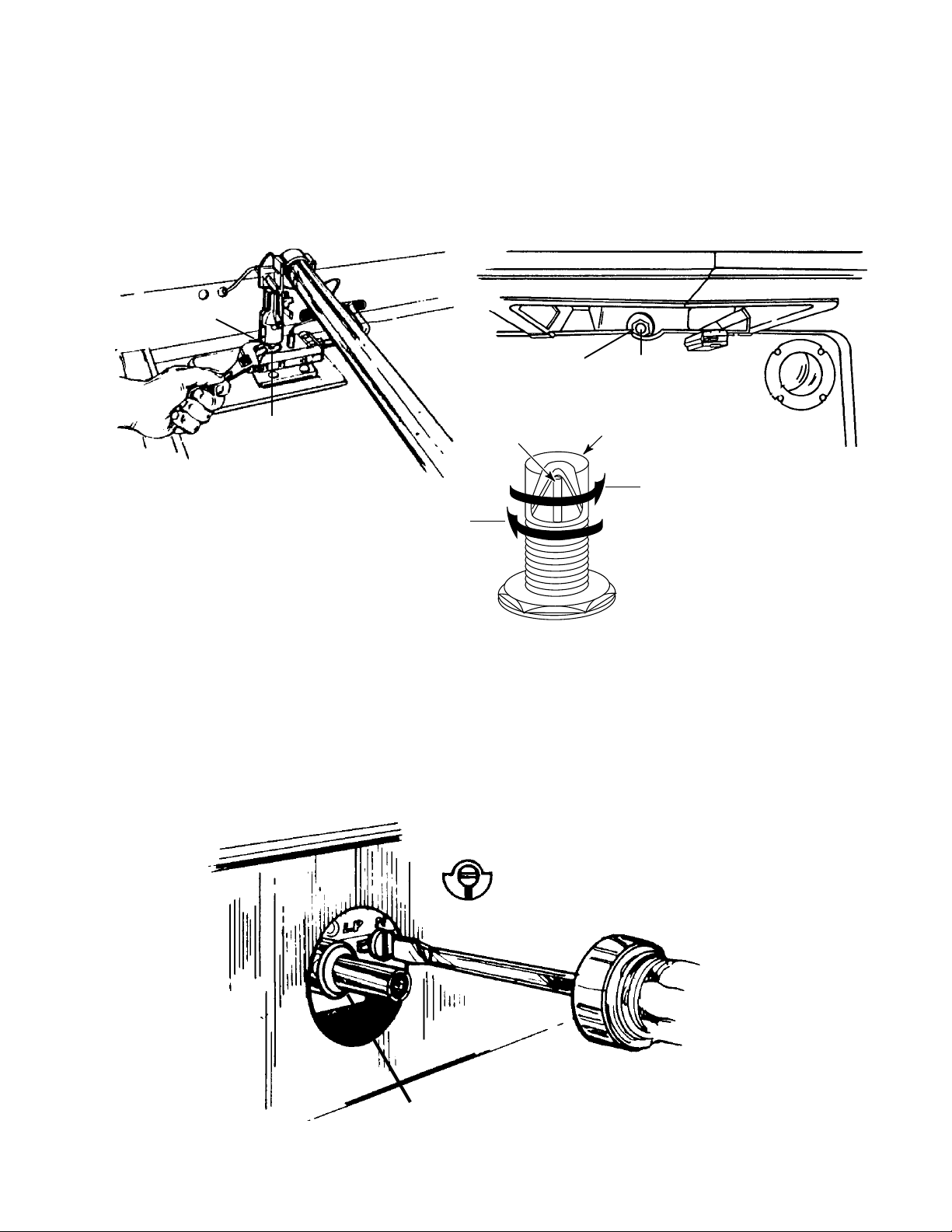
CONVERTING AN OVEN BURNER
L.P. GAS:
DECREASES GAS
AND FLAME SIZE
IN THIS DIRECTION
NATURAL GAS:
INCREASES GAS
AND FLAME SIZE
IN THIS DIRECTION
HOOD
PIN
The oven burners use universal orifice hoods. To convert the oven burners, use a 1/2" combination
wrench and turn the orifice hood 2 to 2-1/2 turns so it is just against the L.P. orifice inlet. DO NOT
OVERTIGHTEN the hood, or you will damage the inlet. The burner flame cannot be properly
adjusted if this conversion is not made. In self-cleaning ovens, both burners must be converted
using the same procedure (see Figures 5-3A and 5-3B).
Bake Orifice
Turn Orifice
Hood Down
2-1/2 turns
Broil Orifice
INSERT
Turn Orifice
Hood Down
2-1/2 turns
Figure 5-3B
Figure 5-3A
CONVERTING AN OVEN THERMOSTAT
If the range is equipped with a standing pilot in the oven, an adjustment for the pilot must be made.
The gas for the oven’s standing pilot is supplied by the oven thermostat. Thermostats used on
standing pilot ranges have a screw to adjust for natural or L.P. gas (see Figure 5-4). Turn the
adjustment screw to the correct setting for the type of gas being used in the oven.
L.P. N
OFF
Figure 5-4
OVEN THERMOSTAT
Page 5-3
Page 68
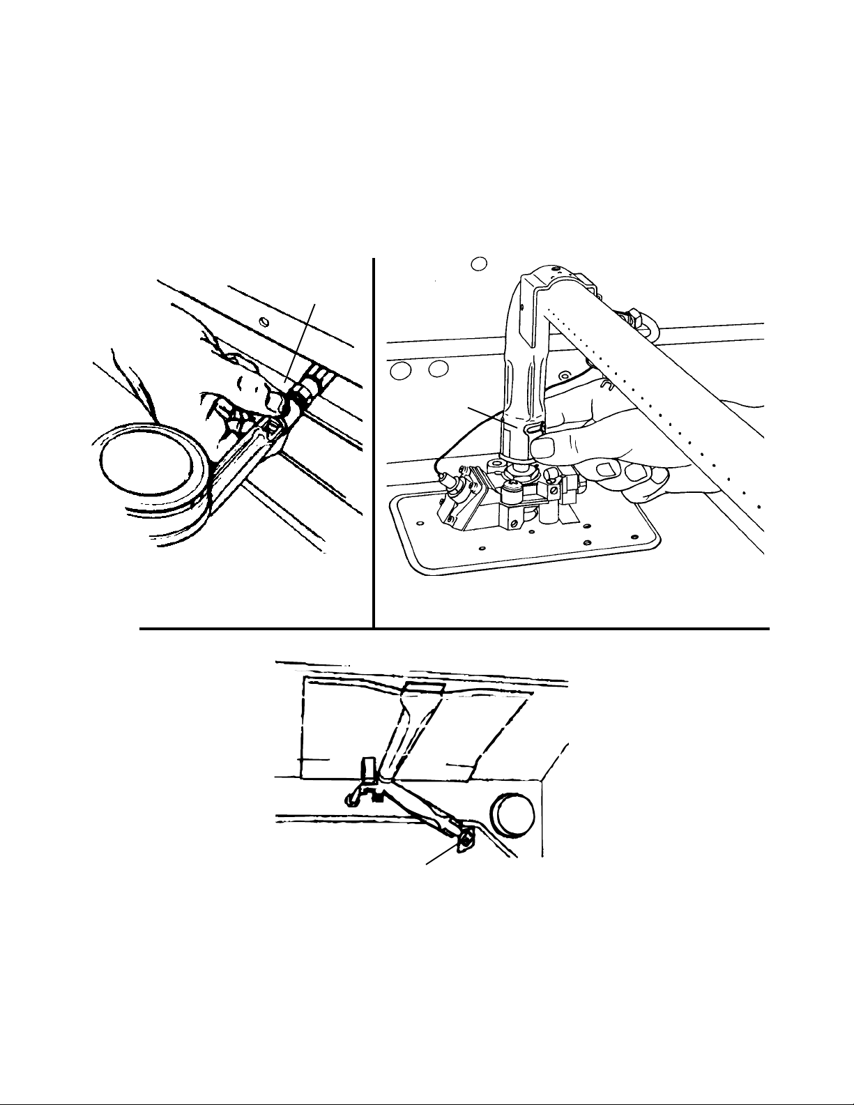
BURNER FLAME ADJUSTMENT
After converting the range to L.P. gas operation, it may be necessary to adjust each burner flame
"
(cooktop and oven burners). A proper cooktop burner flame should be approximately 5/8
have a well-defined blue flame. The oven burner flame should be approximately 3/4
"
a distinct blue flame. If the flame is noisy, or blowing off the burner, it is getting too much air. If the
flame is soft and lazy, it is not getting enough air. Air adjustments can be made by adjusting the
air shutter at each burner (see Figures 5-5A, B, & C). NOTE: There is no air adjustment for sealed
burner cooktops.
Air Shutter
Bake Burner
Air Shutter
Cooktop
Burner
high and
high and have
Figure 5-5A
Broil Burner
Air Shutter
Figure 5-5B
Figure 5-5C
Page 5-4
Page 69

PERFORMANCE CHECK
1. Convert the pressure regulator, cooktop and oven burners, for use with L.P. gas.
Page 5-5
Page 70

— NOTES —
Page 5-6
Page 71
TESTING THE COMPONENTS
WARNING LABELS
This manual is intended for factory-service technicians only. We recommend that customers DO
NOT service their own units, because of the complexity and risk of high-voltage electrical shock.
The following information should be read carefully.
Page 6-1
Page 72
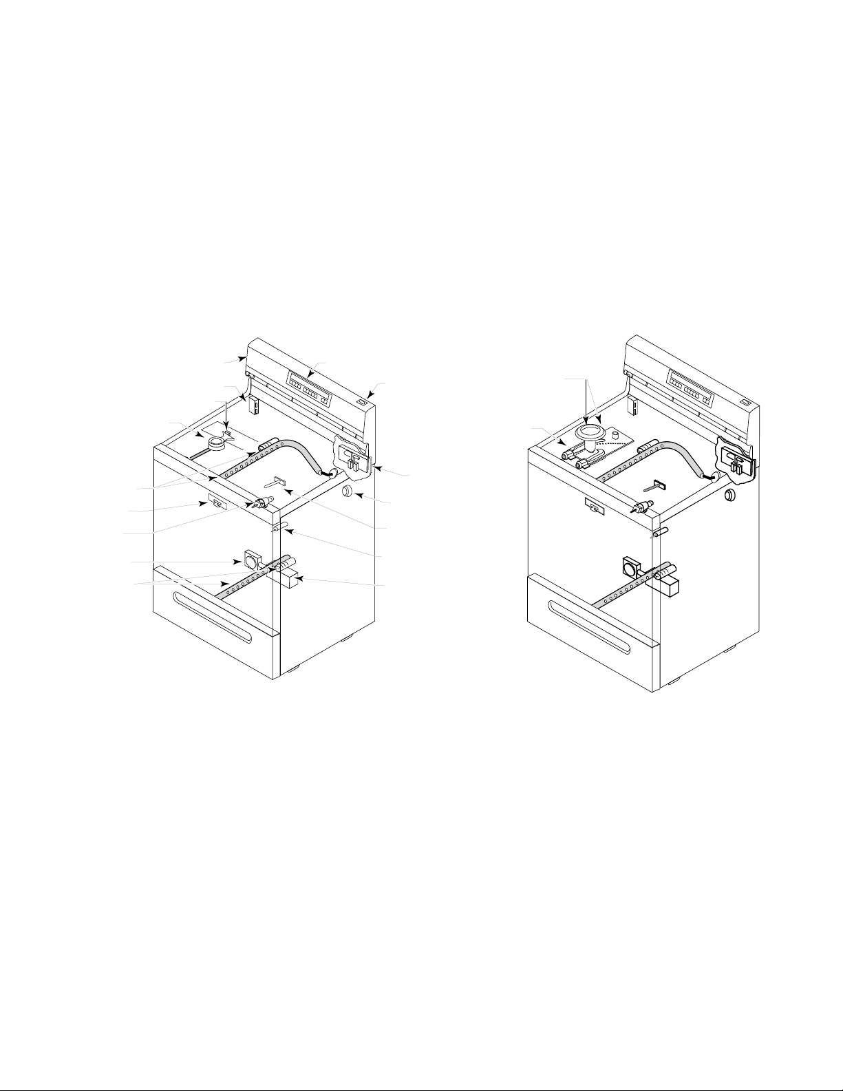
GENERAL INFORMATION
1. When diagnosing a problem, always begin by checking the range for the proper line voltage,
open fuses, and defective components.
2. New ranges that have been in operation for only a short time should be checked for loose
connections or incorrect wiring.
3. When using a test meter, use one that has a sensitivity of 20,000 ohms-per-volt, or greater.
4. The ranges described in this section have spark ignition top burners, and silicon carbide (glowbar) oven igniters with combination bake and broil burners.
5. The following pages provide a general procedure for troubleshooting each of the major
components in the range. The component locations are shown in Figure 6-1.
IGNITOR SPARK MODULE
CONVENTIONAL
BURNER
BROIL BURNER
& IGNITOR
DOOR LATCH
GAS VALVE
& SPARK IGNITOR
SWITCH
PRESSURE
REGULATOR
BAKE BURNER
& IGNITOR
CONSOLE
BURNER IGNITOR
OVEN CONTROL
MANUAL OVEN
LIGHT SWITCH
TEMPERATURE SENSOR
AUTOMATIC OVEN
LIGHT SWITCH
GAS SAFETY
VALVE
DOOR LATCH
SWITCHES & DOOR
LATCH SOLENOID
OVEN LIGHT
Figure 6-1
SEALED BURNER
& BURNER IGNITOR
VENTURI
Page 6-2
Page 73
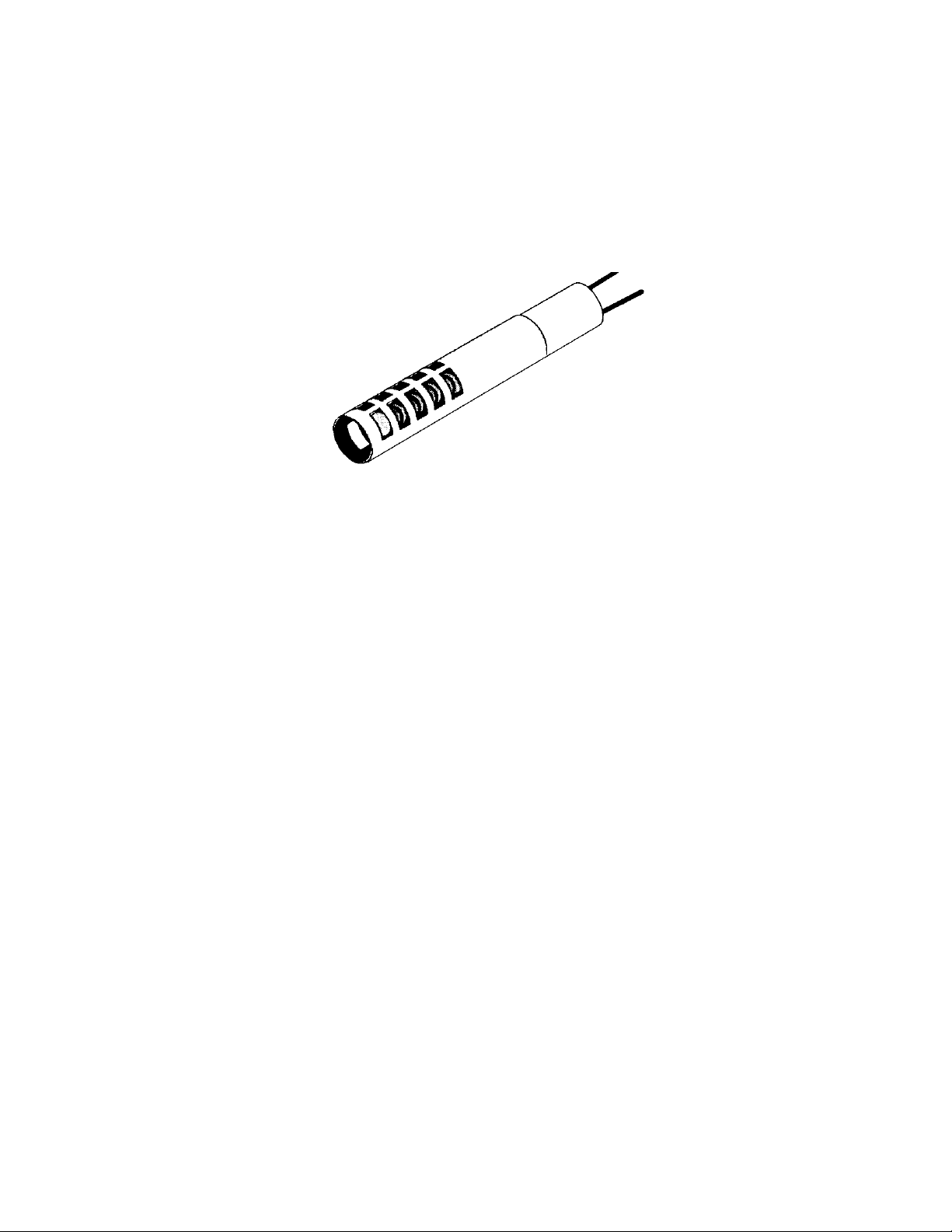
TESTING AN OVEN GLO-BAR IGNITER
If the glo-bar ignitor (see Figure 6-2) does not glow, perform the following steps to test it:
1. Turn off the gas and electrical power to the range.
2. Disconnect the oven igniter quick-disconnect plug from the main harness connector.
3. Connect an ohmmeter across the wire ends or terminals of the glo-bar. If the meter reads over
1100 Ω, replace the igniter.
Figure 6-2
Carborundum Ignitor
Steady State Current = 3.0 Amps @ 115 ±1 VAC @ 75˚F ±10˚
Ambient.
Cold Resistance = 500 Ω TO 1100 Ω @ 75˚F ±10˚ Ambient.
Maximum Operating Temperature Not To Exceed 2650˚F @
115 ±1 VAC @ 75˚F ±10˚ Ambient.
Page 6-3
Page 74
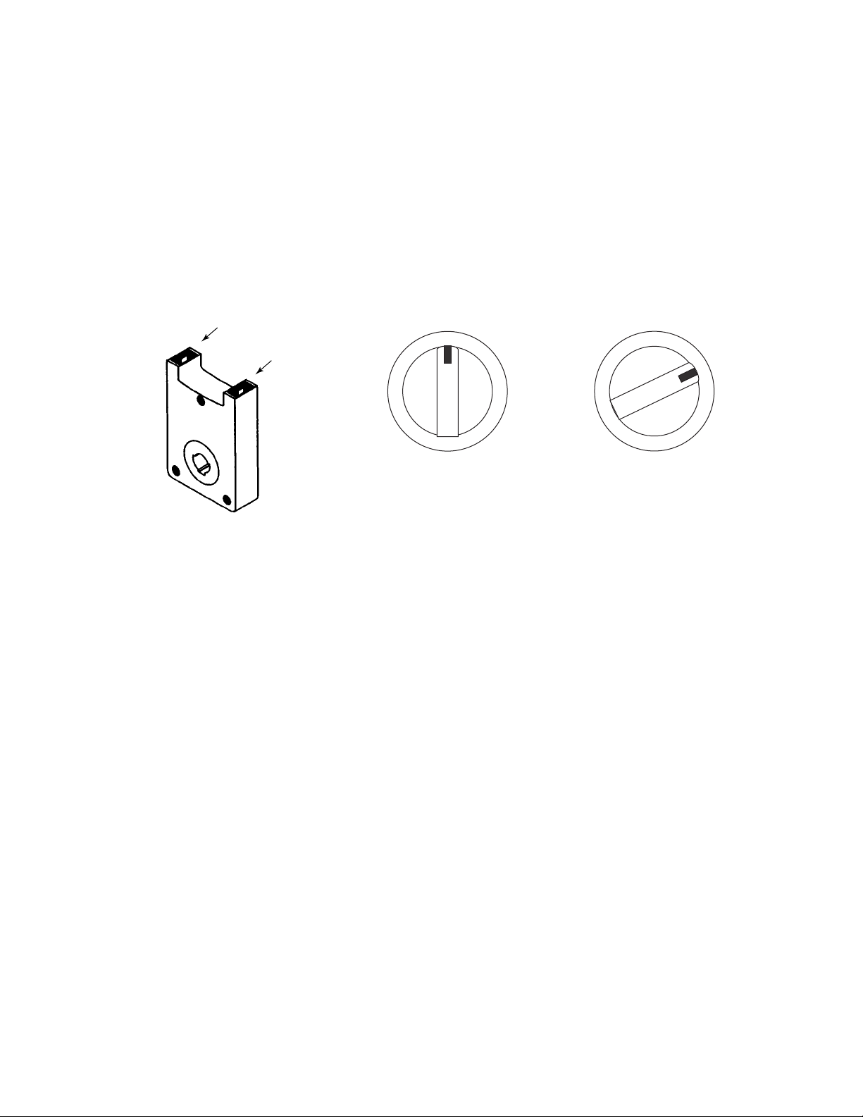
TESTING AN IGNITOR SWITCH
The ignitor switch (see Figure 6-3A) is located on the gas control valve stem and closes when the
knob is turned to the LITE position (see Figure 6-3B) to provide power to the ignitor spark module.
To test a switch:
1. Turn off the gas and electrical power to the range.
2. Disconnect the wires from the ignitor switch terminals.
3. Set the ohmmeter to the R x 1 position.
4. With the control knob in the OFF position, touch the meter leads to the switch terminals. The
meter should indicate
no continuity
.
Terminals
OFF
Control OFF
Switch Open
LITE
Control Set To Lite
Switch Closed
Figure 6-3B
Figure 6-3A
5. Turn the control knob to the LITE position, and the meter should indicate
If the readings are not as indicated in the test, replace the switch.
OFF
continuity
LITE
.
Page 6-4
Page 75
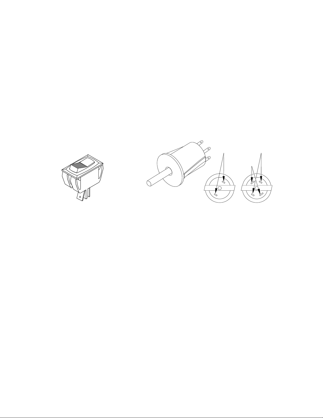
TESTING AN OVEN LIGHT SWITCH
The oven light switch can be a rocker-type, (see Figure 6-4A), or a pushbutton-type (see Figure
6-4B) switch. The rocker switch is manually operated, and the pushbutton switch is operated by
the oven door. The pushbutton switch may have more that two terminals, depending on the model.
The terminal callouts for the two types of pushbutton switches are shown below. NOTE: It may be
necessary to pull the range out of its location.
To test a switch:
1. Turn off the gas and electrical power to the range.
2. Set the ohmmeter to the R x 1 position.
3. Touch the meter leads to the rocker or pushbutton switch terminals and operate the switch.
The meter should switch between
continuity
(see the following illustrations). If the meter does not indicate a change, replace the switch.
and
no continuity
as the switch is operated
NORMALLY OPEN
(GOLD) CONTACTS
DOOR OPEN = SWITCH OPEN
NORMALLY CLOSED
DOOR OPEN =
SWITCH CLOSED
Rocker Switch Pushbutton Switch
Figure 6-4A
Figure 6-4B
Page 6-5
Page 76
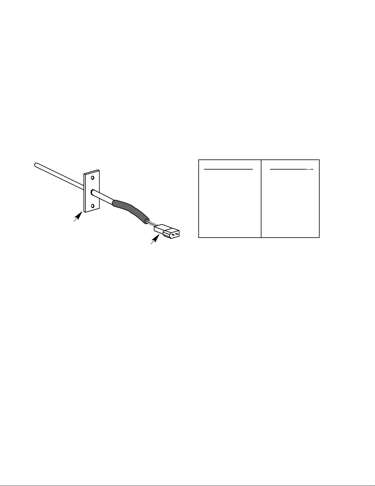
TESTING AN OVEN TEMPERATURE SENSOR
Some oven controls use an oven temperature sensor (see Figure 6-5) to operate the bake, broil,
and self-clean functions. The oven temperature sensor is a “Resistance Temperature Detector
(RTD)” and is composed of a stainless steel tube with a thin film of platinum on the end. The sensor
is usually located inside the oven cavity at one of the upper rear corners. The RTD is nonadjustable,
but it may be checked with an ohmmeter at various temperatures. To test a switch:
1. Turn off the gas and electrical power to the range.
2. Unplug the connector from the oven temperature sensor.
3. Set the ohmmeter to the R x 10 position.
4. Touch the meter leads to the plug pins. The meter should indicate approximately 1100 Ω at
75 ˚F. For resistances at other temperatures, refer to the chart below. NOTE: The readings
are approximate.
Temperature (˚F) Resistance (Ω)
32 1000
75 1100
250 1450
350 1650
450 1850
550 2050
Oven Temperature
Sensor
650 2230
900 2700
Figure 6-5
Connector
Page 6-6
Page 77
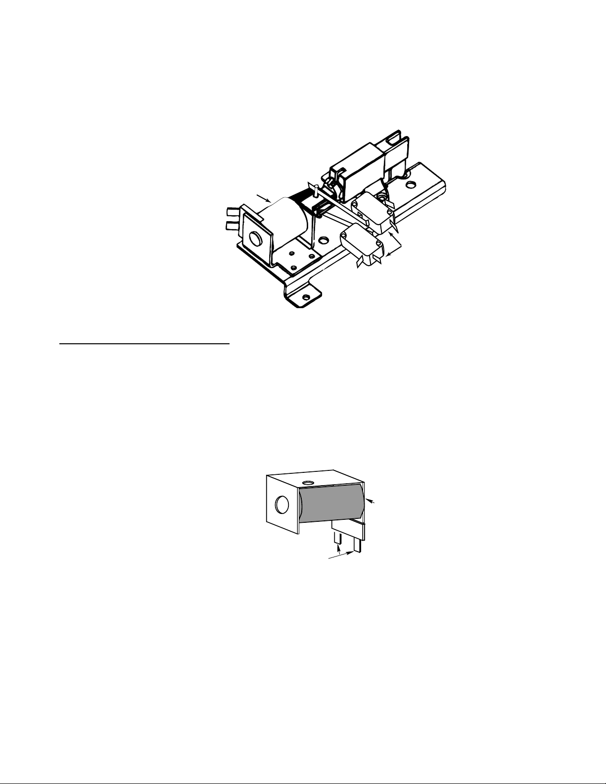
D
TESTING AN OVEN DOOR LATCH
Gas ranges that have a self-clean feature incorporate an oven door latching system, (see Figure
6-6), which locks the oven door during the self-clean cycle. The door latch assembly consists of
a solenoid and one or two switches.
Solenoid
Door Latch
Switches (N.O.)
Figure 6-6
To test the solenoid windings, perform the following steps:
1. Turn off the gas and electrical power to the range.
2. Set the ohmmeter to the R x 1 position.
3. Remove the wire from either solenoid terminal (see Figure 6-7).
4. Touch the ohmmeter leads to the terminals of the solenoid. You should obtain a reading of
between 40 Ω and 70 Ω.
If the reading is not within the range shown, the solenoid may be considered defective and should
be replaced.
SOLENOI
Figure 6-7
TERMINALS
Page 6-7
Page 78
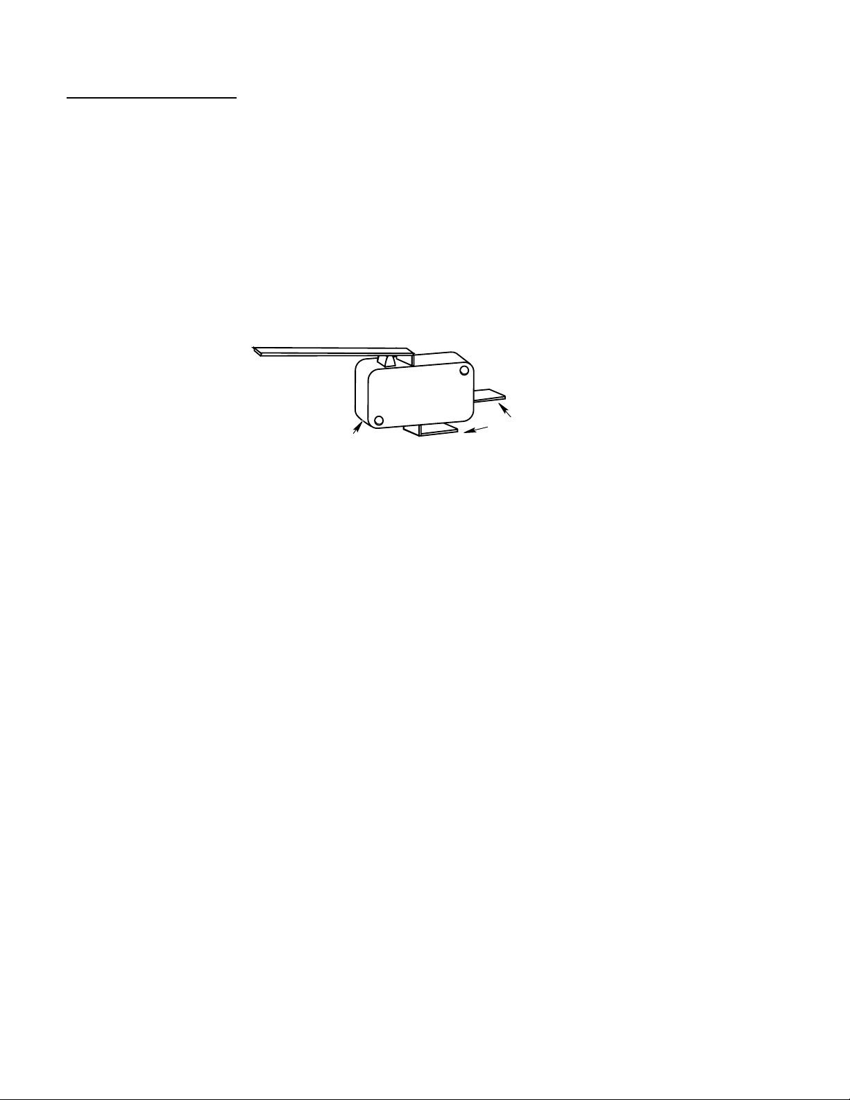
To test the switch(es):
1. Turn off the gas and electrical power to the range.
2. Disconnect the wires from the switch terminals.
3. Set the ohmmeter to the R x 1 position.
4. Connect one of the ohmmeter leads to the common (COM) terminal.
5. Touch the other ohmmeter lead to the normally-open (N.O.) switch terminal. The ohmmeter
should indicate infinity (∞), or an open circuit.
6. Close the switch and the ohmmeter should now indicate continuity (0 Ω).
If the above results are not obtained, the switch is defective and should be replaced.
SWITCH
COM
Figure 6-8
NO
TERMINALS
Page 6-8
Page 79
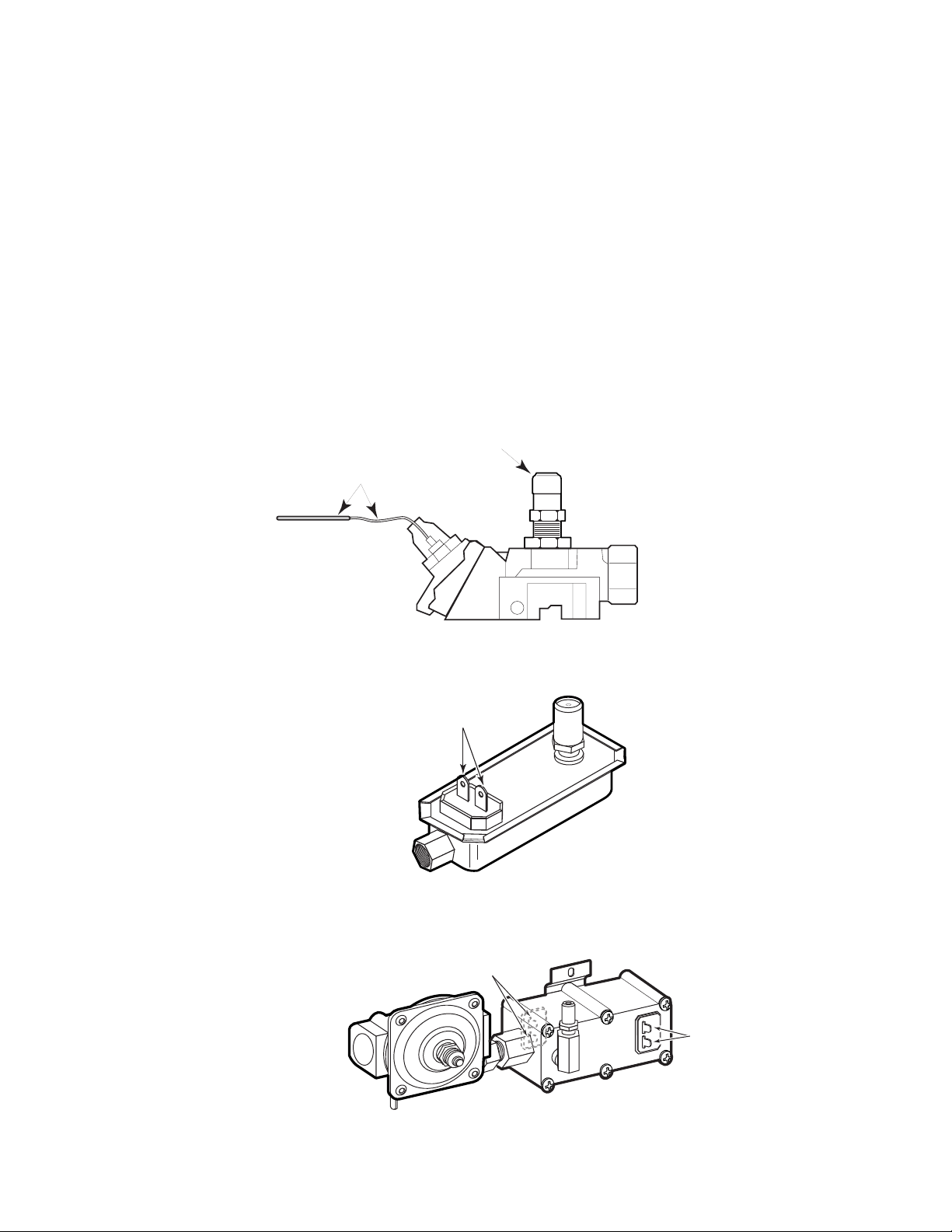
TESTING A GAS SAFETY VALVE
Some gas ranges use an electrically-controlled gas safety valve to control the flow of gas to the
oven burner. The electric safety valve controls the gas flow by means of a bimetal-controlled
diaphragm. Self-clean models have a single inlet, dual outlet, bimetal-operated safety valve. To
prevent miswiring, the bake and broil terminals are sized differently. Several typical safety valves
are shown in Figures 6-9 through 6-11. To test a gas safety valve:
1. Turn off the gas and electrical power to the range.
2. Set the ohmmeter to the R x 1 position.
3. Disconnect the wires from the bake and broil terminals.
4. Touch the meter leads to each set of terminals. The meter should indicate a low resistance
reading of between 1Ω and 5Ω. If the meter indicates an open circuit, or a high resistance,
replace the valve.
Orifice Hood
Heater Sensing
Bulb & Capillary Tube
Figure 6-9
Figure 6-10
Gas Inlet
Standing-Pilot Safety Valve
Terminals
Combination Bake/Broil
Gas Safety Valve
Broil Terminals
Figure 6-11
Bake Terminals
Dual Gas Safety Valve
Page 6-9
Page 80
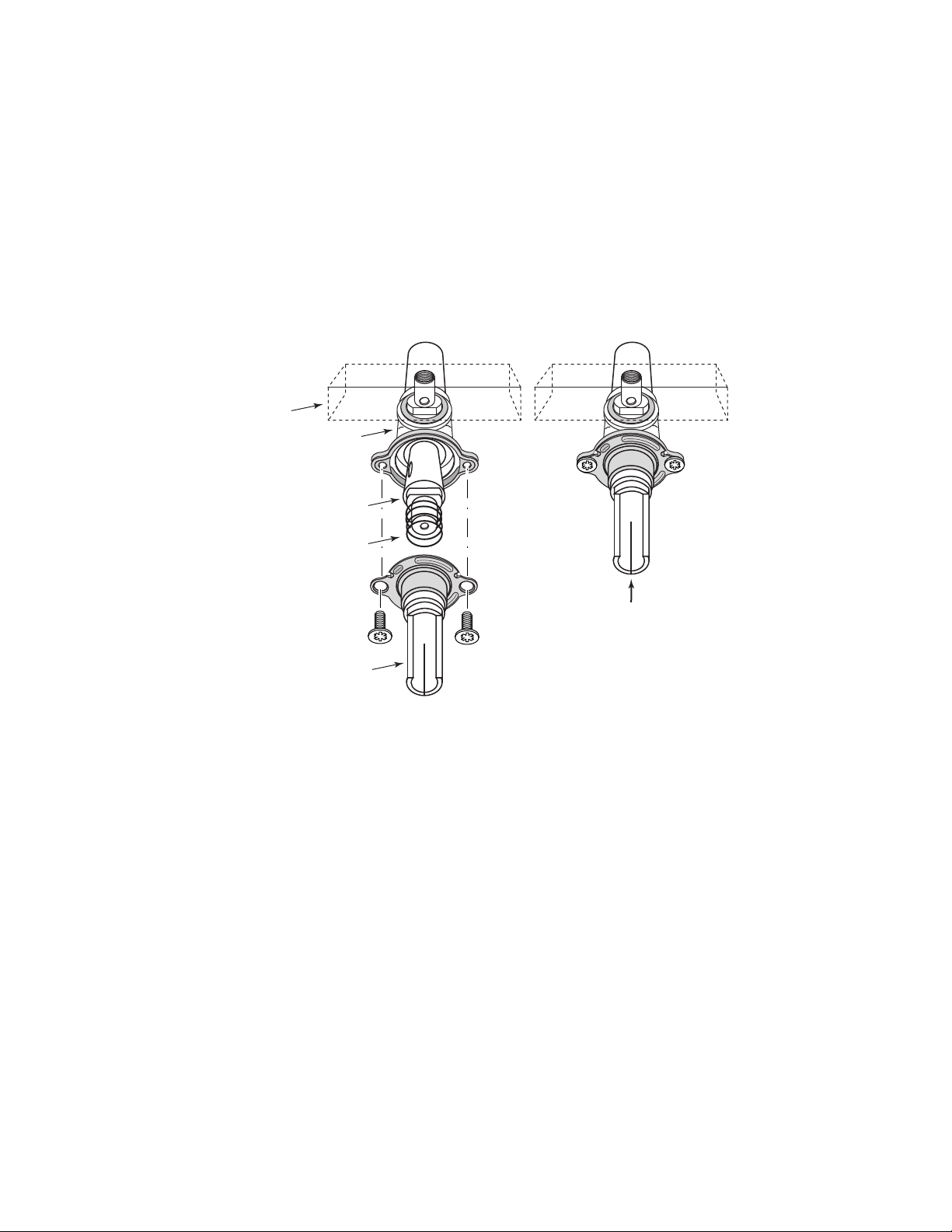
TESTING THE GAS CONTROL VALVES
The top burner gas valves control the gas flow to the top burners. The valve is a barrel and core,
grease sealed, locking type valve (see Figure 6-12). Before the stem can be turned, it must be
pushed in to unlock the valve. Gas flows from the manifold pipe into the rear of the valve and enters
into the hollow core. The core has one large and two small holes in its side. When the stem of the
valve is rotated, the core rotates with it. As the core is rotated, gas is allowed to flow from the large
hole into the mixer elbow.
When the core is rotated 90-degrees, the large hole in the core matches the hole in the barrel
allowing the maximum amount of gas to flow. When the core is rotated past 90˚, the gas flow is
reduced.
Manifold Pipe
Valve Body
Barrel
Spring
Push To Turn
Stem
To test a gas control valve:
1. Gas leak at the valve.
a) Check to see if either the knob or the valve stem is rubbing the control panel. If so, align
the manifold pipe before replacing the valve. If the alignment is good, replace the valve.
Note: Any type of side pressure on the valve stem will cause the valve to leak.
2. The valve stem is hard to turn, or cannot be turned.
a) Check to see if the control panel is preventing the stem from being pushed in. If so, adjust
the manifold pipe. If not, replace the valve.
Figure 6-12
Page 6-10
Page 81
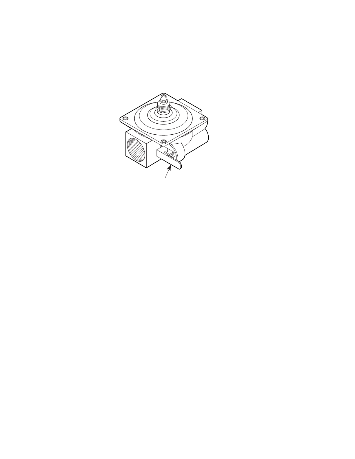
TESTING THE GAS PRESSURE REGULATOR
The pressure regulator is a mechanical device that reduces the higher incoming gas pressure to
a lower outgoing pressure, and maintains a steady, even flow of gas.
The pressure regulator has one outlet that is connected directly to the gas safety valve. The inlet
has a manual shutoff valve so that the gas to the safety valve can be turned off (see Figure 6-13).
N
N
PRESSURE
REGULATOR
Manual Shutoff Valve
Figure 6-13
The common causes of pressure regulator failure are:
a) Ruptured diaphragm.
b) Broken or weak valve.
c) Accumulated debris around the valve seat.
d) Plugged vent.
The pressure regulator is normally replaced rather than serviced, since it has few replaceable or
serviceable parts, and is a relatively inexpensive device.
Use a manometer, or a magnehelic gauge, to test the pressure regulator.
Natural Gas = 4" WCP
L.P. Gas = 11" WCP
If the reading is not within the range shown, the pressure regulator is defective and should be
replaced.
Page 6-11
Page 82

TROUBLESHOOTING CHART
PROBLEM POSSIBLE CAUSE SOLUTION
Gas odor.
Gas odor with all pilots lit or with
electronic ignition.
Surface burner does not light.
Surface burner pilot does not stay
lit.
Pilot light out.
Burner control on slightly.
Gas line leak.
Pilot light out.
Burner pilot port hole blocked.
Burner or flash tube out of position.
No power to range (ranges with
electronic igniters).
Electronic igniter does not spark.
Burner flame openings clogged.
Too much air to burner.
Not enough gas to burner.
Pilot opening blocked.
Pilot light set too low.
Too much air to burner.
Not enough gas to burner.
Ventilate room, then relight pilot.
Turn off burner controls.
Turn off gas to range, ventilate
room, call gas company.
Relight pilot.
Clear burner portholes.
Reposition burner or flash tube.
Make sure range is plugged in.
Also check for blown fuse or
tripped circuit breaker.
Inspect ignitor and ignitor module.
Clean burner.
Adjust air shutter.
Check pressure regulator.
Clear pilot opening.
Adjust pilot light.
Adjust air shutter.
Check pressure regulator.
Surface burner flame low or
uneven.
Surface burner flame too high,
noisy, or blowing.
Surface burner flame yellow or
sooty.
Burner port openings clogged.
Not enough air to burner.
Not enough gas to burner.
Too much air to burner.
Too much gas to burner.
Burner out of position.
Not enough air to burner.
Too much gas to burner.
Clean burner.
Adjust air shutter.
Check pressure regulator.
Adjust air shutter.
Check pressure regulator.
Reposition burner.
Adjust air shutter.
Check pressure regulator.
Page 6-12
Page 83

PROBLEM POSSIBLE CAUSE SOLUTION
Oven burner does not light.
Oven burner pilot does not stay lit.
Oven does not hold set tempera ture so that oven bakes unevenly.
Pilot light out.
Pilot light set too low.
Clock timer set improperly.
No power to range (ranges with
electronic igniters).
Electronic igniter does not spark.
Fuses blown (ranges with glow-bar
igniter).
Glow-bar igniter faulty.
Thermostat, selector switch, or
safety valve faulty.
Pilot light set too low.
Pilot opening blocked.
Door misaligned or gasket faulty.
Burner port openings clogged.
Thermostat or capillary tube faulty.
Relight pilot.
Adjust pilot light.
Refer to “Use and Care manual”
and reset timer.
Make sure that range is plugged in.
Also check for blown fuse or
tripped circuit breaker.
Inspect igniter and ignitor module.
Test fuse.
Check Glow-bar igniter.
Check pressure regulator.
Adjust pilot light.
Clear pilot opening.
Check door and oven gasket.
Clear burner openings.
Replace thermostat assembly.
Self-cleaning oven does not
clean.
Control setting incorrect.
Oven door not locked.
Thermostat, selector switch, or
door lock faulty.
Door misaligned or gasket faulty.
No power to range.
Check “Use and Care manual” and
reset controls.
Close and lock door.
Check door lock assembly.
Check door and oven gasket.
Make sure that range is plugged in,
check for blown fuse or tripped
circuit breaker.
Page 6-13
Page 84
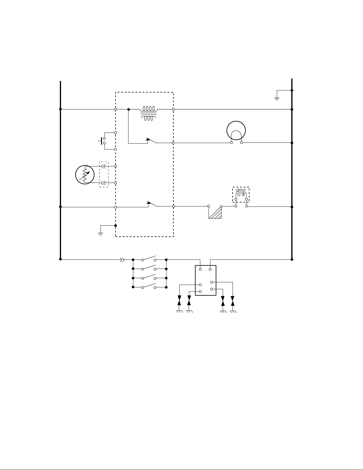
SCHEMATIC DIAGRAMS
Standard Range
L1
BK
BK
DOOR
OVEN
TEMP
SENSOR
BK
SW.
GND
OVEN CONTROL
P4-3 P4-1
TRANSFORMER
Y
P3-3
Y
P3-4
V
P3-6
P3-7
V
P2-2
GN
P3-5
P4-4
P2-1
OVEN LIGHT
BK
RR
BAKE VALVE
BAKE IGNITOR
N
GND
W
W
W
SURFACE BURNER
IGNITOR SWITCHES
IGNITOR MODULE
Page 6-14
Page 85
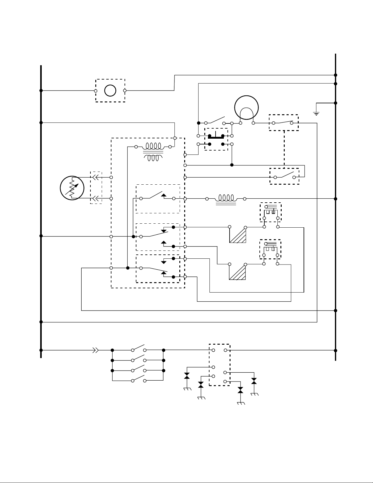
L1
BK
Self-Clean Range
N
TIMER
(IF EQUIPPED)
BK
OVEN
TEMP
SENSOR
BK
MANUAL
OVEN LIGHT
SWITCH
(IF EQUIPPED)
OVEN CONTROL
TRANSFORMER
V
V
P1-6
P1-7
LATCH SOLENOID
RELAY
P3-1
BROIL
RELAY
P2-1
BAKE
RELAY
P5
W
P1-1
P1-5
P1-3
P4
P3-4
P3-2
P2-4
P2-2
Y
DOOR
LIGHT SW.
BU
BR
RR
BU
W
W
OVEN LIGHT
W
W
LATCH
SOLENOID
BAKE IGNITOR
BROIL IGNITOR
DOOR
LATCH SW.
GND
BK BK
N.O.
W
Y
GY
N.O.
DOOR
W
LATCH SW.
BAKE VALVE
BU
BROIL VALVE
W
BK
SURFACE BURNER
IGNITOR SWITCHES
IGNITOR MODULE
Page 6-15
Page 86
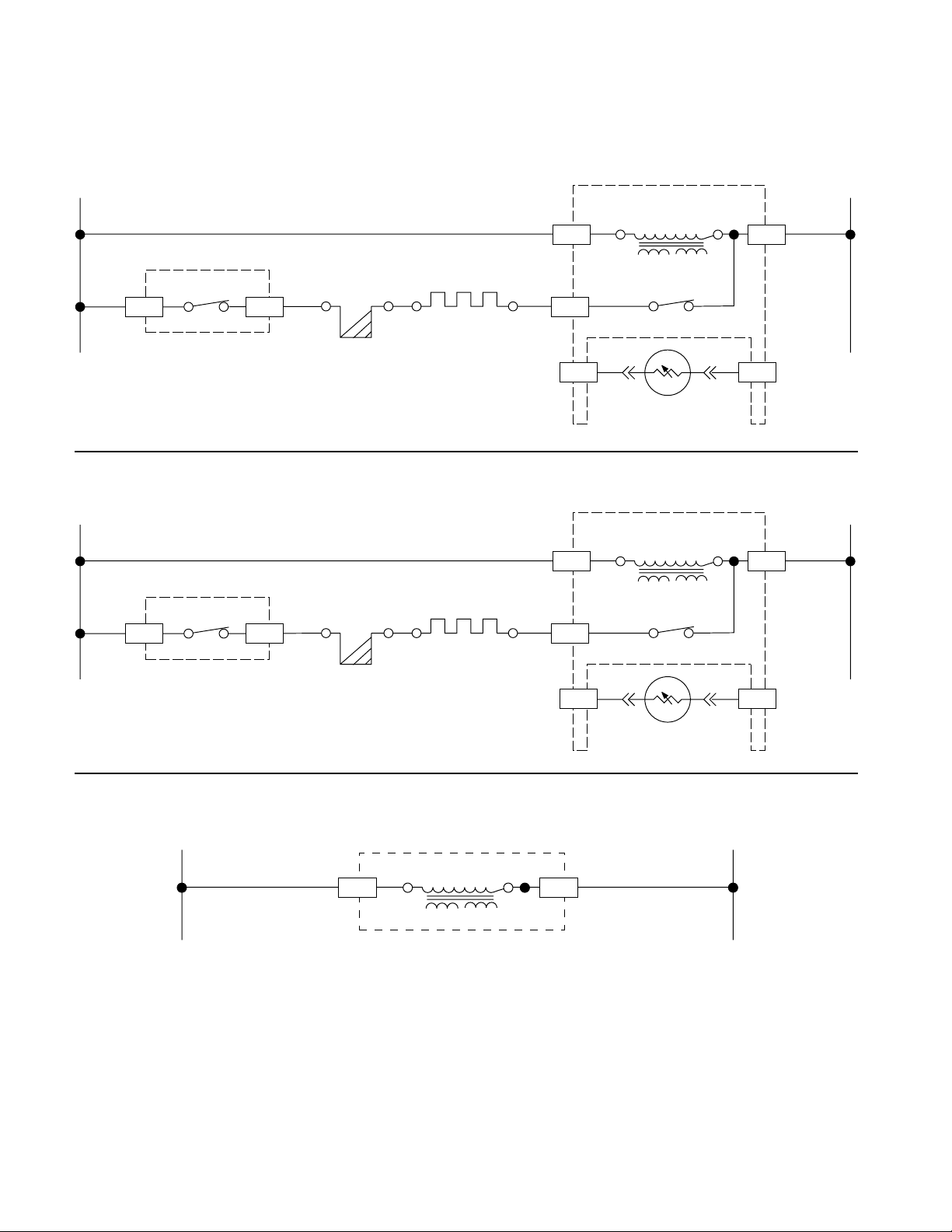
STRIP CIRCUITS
BAKE
OVEN CONTROL
L1 N
BK
OVEN CONTROL
BROIL RELAY
P3-4P3-1
BAKE IGNITOR
R
BAKE VALVE
P5 P2-1
TRANSFORMER
W
P2-4
BAKE RELAY
VV
WBK
P1-6 P1-7
SENSOR
BROIL
OVEN CONTROL
L1 N
BK
OVEN CONTROL
BROIL RELAY
P3-2P3-1
BROIL IGNITOR
BU
BROIL VALVE
P5 P2-1
TRANSFORMER
W
P2-2
BAKE RELAY
WBK
CONTROL BOARD POWER
L1
OVEN CONTROL
TRANSFORMER
P5 P2-1
VV
P1-6 P1-7
SENSOR
N
WBK
Page 6-16
Page 87
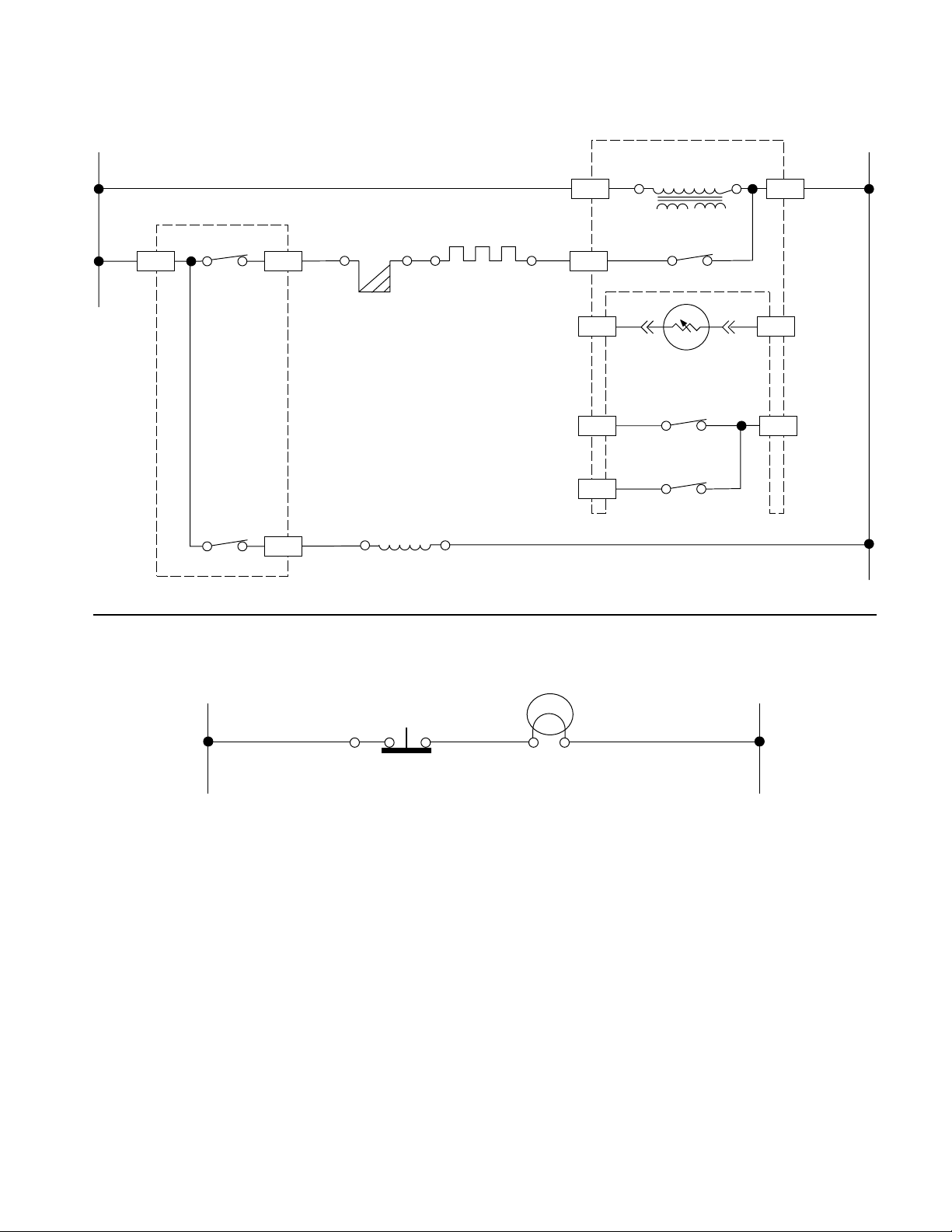
SELF-CLEAN
OVEN CONTROL
L1 N
BK
OVEN CONTROL
P3-1
* PULSE 1 SECOND
BROIL RELAY
LATCH RELAY*
(N.O.)
P3-4
P4
BAKE IGNITOR
BU
BR
LATCH
SOLENOID
BAKE VALVE
W
P5 P2-1
TRANSFORMER
W
P2-4
BAKE RELAY
VV
P1-6
SENSOR
DOOR LATCH
P1-3
SWITCH
DOOR LATCH
SWITCH
BU GY
GYY
WBK
P1-7
P1-5P1-1
OVEN LIGHT
N
OVEN LIGHT
L1
WWBK
Page 6-17
Page 88

— NOTES —
Page 6-18
 Loading...