


TABLE OF CONTENTS
1
I M P O R T A N T
INFORMATION
HOW TO INSTALL
2
THE STAND
3 PREFACE
4
SAFETY
PRECAUTIONS
5 IN THE CARTON
FRONT/BACK
6CONNECTIONS OF LCD TV
TV INSTALLATION
7
DRAWINGS
8 REMOTE CONTROL
9 Menu Operation
10Troubleshooting
11SPECIFICATIONS
|
2 |
|
|
|
|
|
4 |
|
|
|
|
|
5 |
|
|
|
|
|
5 |
|
|
|
|
|
7 |
|
|
|
|
|
8 |
|
|
|
|
Power Cord Connection |
9 |
Antenna Connection |
9 |
AV Connection |
10 |
YPbPr(component) Connection |
10 |
VGA(PC) Connection |
11 |
COAX Connection |
11 |
HDMI Connection |
12 |
Service Port Function |
12 |
|
|
|
|
Remote control instructions in TV mode |
13 |
Remote control setup |
14 |
|
|
|
|
Setup Wizard |
15 |
Select Input Source |
16 |
Basic Operation |
16 |
Picture Menu |
17 |
Sound Menu |
20 |
Channel Menu |
23 |
Parental Control |
25 |
Setup Menu |
28 |
Other Menu |
30 |
Picture Menu |
31 |
|
|
|
|
|
35 |
|
|
|
|
|
36 |
English
1

IMPORTANT INFORMATION
English
The lightning flash with arrowhead symbol, within an equilateral triangle, is intended to alert the user to the presence of un-insulated dangerous voltage within the products enclosure that may be of sufficient magnitude to constitute a risk of electric to persons.
The exclamation point within an equilateral triangle is interded to aler the user to the presence of important operating and maintenance (servicing) instruction the literature accompanying the appliance.
CAUTION: USE OF ANY CONTROLS, ADJUSTMENTS, OR PROCEDURES OTHER THAN THOSE SPECIFIED HEREIN MAY RESULT IN HAZARDOUS RADIATION EXPOSURE.
CAUTION: These servicing instructions are for use by qualified service personnel only. To reduce the risk of electric shock, do not perform any servicing other than that contained in the operating instructions unless you are qualified to do so.
Refer to service manual for servicing instructions.
Important Safety Instructions
Note:
1.Read these instructions. 2.Keep these instructions. 3.Heed all warnings.
4.Follow all instructions. 5.Do not use near water. 6.Clean only with dry cloth.
7.Do not block any ventilation openings. Install in accordance with the manufacturer's instructions. 8.Do not install near any heat sources such as radiators, heat registers, stoves, or other apparatus
(including amplifiers) that produce heat.
9.Do not defeat the safety purpose of the polarized or grounding-type plug. A polarized plug has two blades with one wider than the other. A grounding type plug has two blades and a third grounding prong. The wide blade or the third prong are provided for your safety. If the provided plug does not fit into your outlet, consult an electrician for replacement of the obsolete outlet.
2

IMPORTANT INFORMATION
10.Protect the power cord from being walked on or pinched particularly at plugs, convenience receptacles, and the point where they exit from the apparatus.
11.Only use attachments / accessories specified by the manufacturer.
12.Use only with the cart, stand, tripod, bracket, or table specified by the manufacturer, or sold with the apparatus. When a cart is used, use caution when moving the cart / apparatus combination to avoid injury from tip-over.
English
13.Unplug this apparatus during lightning storms or when unused for long periods of time.
14.Refer all servicing to qualified service personnel. Servicing is required when the apparatus has been damaged in any way, such as power-supply cord or plug is damaged, liquid has been spilled or objects have fallen into the apparatus, the apparatus has been exposed to rain or moisture, does not operate normally, or has been dropped.
15.Apparatus shall not be exposed to dripping or splashing and that no objects filled with liquids, suchas vases, shall be placed on the apparatus.
16.WARNING:To reduce the risk of fire or electric shock, do not expose this apparatus to rain or moisture. 17.Mains plug or appliance coupler is used as the disconnect device, shall be readily operable.
3
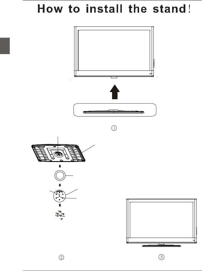
HOW TO INSTALL THE STAND
English
Limit
Base cover
Fixed-ring base
Hole spacing
Rotating base fixed plate
Screw holes


 Screws
First, fix the base cover to the fixed-ring base; then, let the rotating base fixed plate align the three limit pillar; Last, fix it with the screws.
4

PREFACE
3. PREFACE
Thank you for buying this TV! Please read this manual thoroughly before operating the TV. Make sure the TV was not damaged in transit. Should the TV be damaged, do not install it and contact your dealer. Check that you have all the accessories according to the model.
4. SAFETY PRECAUTIONS
Put the TV on a stable surface.
Do not place any material on the TV.
Minimum distances
10cm |
10cm 5cm |
Do not use the TV with fixtures other than those provided or
20cm
suggested by the manufacturer.
Do not block or cover the ventilation openings on the TV.
If you have a wall mount, check that it is steady.
Power cord and cables must be properly routed and protected to prevent people from stepping on them and causing the TV to fall.
English
5

SAFETY PRECAUTIONS
Keep the TV dry and away from humidity.
English
Keep the TV away from heat sources.
Unplug the TV before cleaning it. Do not use solvent or liquid to clean the TV.
Only clean the TV with a soft and dry cloth.
In case of troubleshooting, do not use spare parts other than those suggested by the manufacturer. Using inadequate spare parts can
lead to electric shocks, short-circuits, fire or other incidents.
Unplug the TV during lightning storms or when unused for long periods of time.
6

IN THE CARTON
5. IN THE CARTON
PO WE R MU TE
DI SP LAY
ASPECT
ME NU EX IT
OK
EN TE R
SL EE P SO UR CE
CC FAV LIST MTS
LCD TV SET |
Remote Control |
|
|
1.5V |
|
|
|
V |
|
.5 |
|
|
1 |
|
Power Cable |
AAA Batteries |
Quick Connect Guide
USER'S MANUAL |
Quick Connect Guide |
Warranty Card
Warranty Card |
Small cover for back cover |
7
English
English
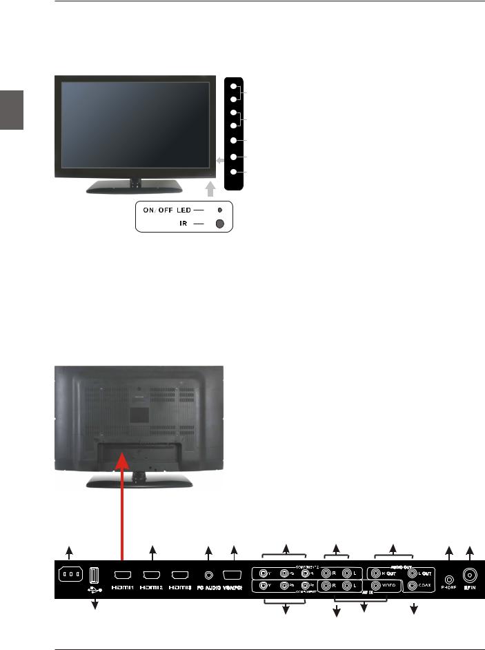
FRONT/BACK CONNECTIONS OF LCD TV
6. FRONT/BACK CONNECTIONS OF LCD TV
Front View
VOL+ 4
VOL-
CH+ 3
CH-
2
MENU
1
SOURCE
5
POWER
1.Press“SOURCE”to select the input source.
2.Press “MENU”to bring up the main menu on the screen.
3.Press“CH+”or “CH-”to scan through channels.
4.Press“VOL+”or “VOL-”to increase or decrease the volume.
5.Press“POWER” button to turn the TV on or off.
6.POWER INDICATOR: Shows amber in standby mode.
Shows amber or blue when your TV is switched on.
7.REMOTE SENSOR: infrared sensor for the remote control.
7
6
Back View and Control Connections
1.AC IN: Main power input.
2.HDMI1/HDMI2/DMI3: Connect the HDMI output
jack of DVD.
3. PC AUDIO: Connect the Audio output jack of PC.
4.VGA(PC): Connect the PC-RGB output jack of PC.
5.YPbPr1/YPbPr2: Connect the YPbPr output jack of DVD or VCR.
6.Y-L/R1,Y-L/R2: For YPbPr audio.
7.VIDEO: Connect the Video input jack of DVD or VCR.
L/R: For VIDEO audio.
8.AUDIO OUT: Connect to the audio equipment.
9.PHONE: Connect the headphone.
10.RF IN: Connect the antenna.
11. USB SERVICE: USB Port for Factory Use Only.
12. COAX out: Connect the COAX receiver.
1 |
2 |
3 |
4 |
5 |
6 |
|
8 |
9 |
10 |
|
|
|
|
|
|
|
|
|
|
|
|
5 |
|
|
|
|
|
|
|
AC IN |
|
|
Y1 |
Pb1 Pr1 |
Y-R1 Y-L1 |
VIDEO COAX |
|
|
|
|
11 |
|
|
|
|||||
|
|
|
|
|
|
|
|
|
|
|
|
|
|
|
|
|
|
|
|
|
|
|
5 |
6 |
7 |
|
12 |
|
|
8
TV INSTALLATION DRAWINGS
7. TV INSTALLATION DRAWINGS
Power Cord Connection
- Connect the power cord correctly as shown. |
English |
|
- Press the POWER switch of your LCD TV to switch on the LCD TV. The power indicator |
||
|
||
on the front panel lights up in amber or blue. |
|
AC IN
Antenna Connection
To ensure good picture and sound, TV antenna system needs to be installed. The antenna system as shown can be sourced from TV equipment shops, which will provide service for correct installation and connection. After installation, insert the 75-ohm antenna plug into the antenna jack as shown.
VHF ANTENNA |
UHF ANTENNA |
OUTDOOR
ANTENNA
AMPLIFIER
INDOOR
ANTENNA RF IN
AMPLIFIER
75 OHM
ANTENNA PLUG
POWER PLUG OF
ANTENNA
AMPLIFIER
9

English
TV INSTALLATION DRAWINGS
AV Connection
Connect the VIDEO and AUDIO output jack of the DVD or VCR to the VIDEO jacks on the set using the RCA cable. Match the jack colors: Video is yellow, Audio left is white, and Audio right is red. Select the AV input source using the SOURCE button on the remote control.
5
TV Back
Y1 Pb1 Pr1 Y-R1 Y-L1
Video Cable
VIDEO |
R |
L |
DVD or VCR Back
DVD or VCR
YPbPr(Component) Connection
Connect the YPbPr output of the DVD or VCR to the YPbPr input on the set. The picture quality is improved; compared to connecting a regular VCR to the video input. Connect the Audio output of the DVD or VCR to the Audio input jacks on the set using the RCA cable.
Match the jacks colors :Y is green,Pb is blue,Pr is red,Audio left is white and Audio right in red.
Select component input source using the SOURCE button on the remote control.
TV Back
TV Back
AUDIO cable |
AUDIO cable |
YPbPr cable |
YPbPr cable |
|
|
|
|
Y Pb Pr R L |
|
|
|
|
|
Y Pb Pr R L |
|
||||||||||||||||
|
|
|
|
|
|
|
|
DVD or VCR Back |
|
|
|
|
|
|
|
|
DVD or VCR Back |
||||||||||
|
|
|
|
|
|
|
|
|
|
|
|
|
|
|
|
|
|
|
|
|
|
|
|
|
|
|
|
|
|
|
|
|
|
|
|
|
|
|
|
|
|
|
|
|
|
|
|
|
|
|
|
|
|
|
|
|
|
|
|
|
|
|
|
|
|
|
|
|
|
|
|
|
|
|
|
|
|
|
|
|
|
|
|
|
|
|
|
|
|
|
|
|
|
|
|
|
|
|
|
|
|
|
|
|
|
|
|
|
|
|
|
|
|
|
|
|
|
|
|
|
|
|
|
|
|
|
|
|
|
|
|
|
|
|
|
|
|
|
|
DVD or VCR |
DVD or VCR |
10
 Loading...