


TECHNICAL
SPECIFICATIONS
Q7RD Series |
FEATURES and BENEFITS |
|
|
|
|||
Single Packaged Heat Pump, |
• Quality Compressor: State of the art compressor is standard |
||
equipment. |
|||
Single Phase |
• R-410A Refrigerant: Earth friendly non-ozone depleting |
||
13 SEER, R-410A |
refrigerant. |
||
• Hi/Low Pressure Switches: Ensure long compressor life. |
|||
2 thru 5Ton Units |
• CopperTube / Aluminum Fin Coils: Outdoor coils are designed |
||
Cooling: 24,000 to 56,000 Btuh |
to optimize heat transfer, minimize size and cost, and increase |
||
Heating: 24,000 to 54,400 Btuh |
durability and reliability. |
||
|
• Anteater Evaporator Coil: for increased resistance against |
||
The Q7 Series single packaged heat pumps are high |
formicary corrosion, the number one cause of coil leaks. |
||
~ The 2, 2.5 and 3 ton models include all-aluminum |
|||
efficiency self contained cooling and heating units that |
|||
Anteater Micro-channel technology. |
|||
can be installed on a slab. Units are ETL and ETLc listed. |
|||
~ The 3.5, 4 and 5 ton models include Anteater™ tubing |
|||
|
|||
|
technology. |
||
|
• DesignedusingGalvanizedSteel:with a polyester urethane coat |
||
|
finish. The 950 hour salt spray finish is 1.5 mil thick and resists |
||
|
corrosion 50% better than comparable units. |
||
|
• Compact Footprint and Profile: make the Q7 Series easy to |
||
|
install and transport. |
||
|
• 0” Clearance: to combustibles on duct side of the unit allows |
||
|
for installations in tight areas. |
||
|
• Wire guard coated with Earth Friendly Epoxy and plastic |
||
|
mesh hail guard: A guard that will never rust and protects the |
||
|
units coil from being damaged. |
||
|
• Raised Base Pan: allows water to drain away from away from |
||
|
the unit. |
||
|
• Easy Compressor and Control Access: Designed to make |
||
|
servicing easier for the contractor, access panels are provided |
||
|
to all controls and the compressor from the side of the unit. |
||
|
• Easy access: to the evaporator coil for cleaning and general |
||
|
maintenance. |
||
|
• Removable Top Grille Assembly: Allows ease of service to |
||
|
the fan motor. |
||
|
• Time/TemperatureDefrost:areliable,industrystandardcontrol |
||
|
offers various time settings to meet any type climate. |
||
|
• Five Minute RestartTime Delay: when the units shuts down, |
||
|
a five minute delay keeps the unit from restarting, eliminating |
||
|
the highest cause of compressor failure. |
||
|
• Liquid Line Filter Driers: Factory installed at a convenient |
||
|
location for service. |
||
|
• AccessibleServiceValves:simplifyservicingoftherefrigeration |
||
|
system. |
||
|
• Suction Accumulator: provides protection from liquid flood |
||
|
back and future compressor failures. |
||
|
• Permanently Lubricated Condenser Motor: A heavy duty |
||
|
PSC motor for long lasting reliability and quiet operation. |
||
|
• Low voltageTransformer: Includes 3 Amp fuse to protect low |
||
|
voltage circuit. |
||
|
• DrainTrap Included: design optimizes drainage capabilities. |
||
|
• Outdoor thermostat: is standard equipment. |
||
|
• Optional Electric Heat: Field installed 5 – 20 KW. |
||
|
|
|
|
MODEL IDENTIFICATION CODE
|
|
Q |
7 |
|
R |
|
D |
- |
024 |
|
K |
|
A |
|||||||||||||||
Application |
|
|
|
|
|
|
|
|
|
|
|
|
|
|
|
|
|
|
|
|
|
|
|
|
|
|
|
Revision |
|
|
|
|
|
|
|
|
|
|
|
|
|
|
|
|
|
|
|
|
|
|
|
|
|
|
|
||
Q = Heat Pump |
|
|
|
|
|
|
|
|
|
|
|
|
|
|
|
|
|
|
|
|
|
Electrical Code |
||||||
|
|
|
|
|
|
|
|
|
|
|
|
|
|
|
|
|
|
|
|
|
|
|
|
|
|
|
||
Generation 1, 3, 5, Etc. |
|
|
|
|
|
|
|
|
|
|
|
|
|
|
|
|
|
|
|
|
|
|
K = 208/230-60-1 |
|||||
|
|
|
|
|
|
|
|
|
|
|
|
|
|
|
|
|
||||||||||||
|
Round Duct |
|
|
|
|
|
|
D = 13 SEER |
|
|
|
|
|
|
|
|
|
Nominal Capacity |
||||||||||
|
|
|
|
|
|
|
|
|
|
|
|
|
|
|
|
|||||||||||||
|
|
|
|
|
|
|
|
|
|
|
|
|
|
|
|
|
|
|
|
|||||||||
|
|
|
|
|
|
|
|
|
|
|
|
|
|
|
|
|
|
|
|
x 1000 Btu |
||||||||
|
|
|
|
|
|
|
|
|
|
|
|
|
|
|
|
|
||||||||||||
|
|
|
|
|
|
|
|
|
|
|
|
|
|
|
|
|
|
|
|
|
|
|
|
|
|
|
|
|
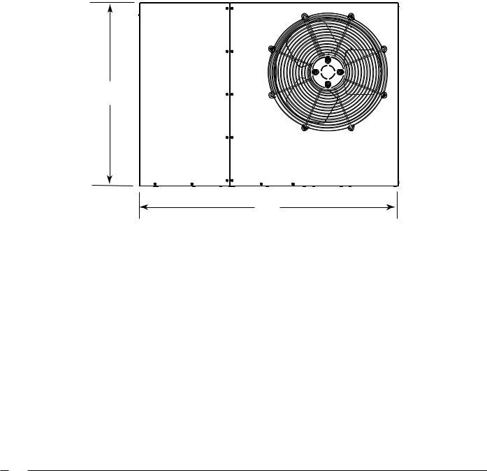
DIMENSIONS
W
L
Top View
Model Number |
(L) |
(W) |
(H) |
A |
B |
|
Q7RD- |
Length |
Width |
Height |
|||
|
|
|||||
|
|
|
|
|
|
|
024K |
49 |
35 |
30.2 |
40.15 |
7.61 |
|
030K |
49 |
35 |
30.2 |
40.15 |
7.61 |
|
036K |
49 |
35 |
30.2 |
35.02 |
2.48 |
|
042K |
49 |
35 |
30.2 |
35.02 |
2.48 |
|
048K |
49 |
35 |
34.2 |
35.02 |
2.48 |
|
060K |
49 |
35 |
38.2 |
35.02 |
2.48 |
|
|
|
|
|
|
|
2

DIMENSIONS Continued
Electric Heater Power Supply
Power Supply
Low Voltage Supply
H |
|
Control |
Blower Access Panel |
||
17.86 |
Access |
|
|
|
|
|
|
|
|
||
|
Panel |
|
|
|
|
|
15.36 |
|
|
|
|
|
|
|
|
|
|
|
10.10 |
|
|
|
1" |
|
|
|
|
|
|
|
|
|
3/4" NPT |
|
|
|
1.38 |
|
Drain Connection |
|
|
|
3.2 |
|
|
|
|
|
|
18.01 |
|
|
|
|
|
|
3.2 |
5.29 |
|
|
|
12.13 |
|
||
|
|
|
|
|
|
Side View
Model Number |
Return |
|
|
|
|
Q7RD- |
Diameter (in) |
|
|
|
|
024K |
14 |
|
|
|
|
030K |
14 |
|
|
|
|
036K |
14 |
|
|
|
|
042K |
14 |
|
|
|
|
048K |
14 |
|
|
A |
|
060K |
14 |
|
3.0 |
5.5 |
B |
|
|
|
9.15 |
|
|
|
|
3.15 |
1" |
|
|
|
|
|
|
|
|
|
|
|
9.04 |
17.50 |
|
|
|
|
|
12" diameter |
14" diameter |
|
|
|
|
Supply Duct |
Return Duct |
|
|
|
|
Opening |
Opening |
Back (Duct) View
3

PHYSICAL Specifications
Q7RD Models
Model No. Q7RD- |
024K |
030K |
036K |
042K |
048K |
060K |
|
|
|
|
|
|
|
Systen Heating and Cooling Capacities |
|
|
|
|
|
|
Cooling Btuh |
24,000 |
29,000 |
34,600 |
40,500 |
46,000 |
56,000 |
SEER |
13 |
13 |
13 |
13 |
13 |
13 |
EER |
11.0 |
11.0 |
11.0 |
11.0 |
11.0 |
10.8 |
Heating Btuh |
24,000 |
28,400 |
34,600 |
40,500 |
44,500 |
54,500 |
HSPF |
7.7 |
7.7 |
7.7 |
7.7 |
7.7 |
7.7 |
Electric Rating — 60 Hz (a) |
|
|
|
|
|
|
Operating Voltage Range |
187 - 253 |
187 - 253 |
187 - 253 |
187 - 253 |
187 - 253 |
187 - 253 |
Min. Circuit Ampacity (a) |
16.9 |
17.5 |
23.7 |
29.3 |
34.2 |
39.9 |
Field Wire Size — AWG (a) |
12 |
12 |
10 |
8 |
8 |
6 |
Delay Fuse — Max. (b) |
25 |
25 |
35 |
45 |
50 |
60 |
Total Unit — AMPS |
14.5 |
15.0 |
19.9 |
24.8 |
28.7 |
33.3 |
Compressor |
|
|
|
|
|
|
Volts |
208 - 230 |
208 - 230 |
208 - 230 |
208 - 230 |
208 - 230 |
208 - 230 |
Rated Load Amps |
9.6 |
10.1 |
15.0 |
17.9 |
21.8 |
26.4 |
Lock Rotor Amps |
60.5 |
60.0 |
88 |
112 |
117 |
134 |
Condenser Motor |
|
|
|
|
|
|
Fan Motor — HP - RPM |
1/8 - 1100 |
1/8 - 1100 |
1/4 - 1100 |
1/4 - 1100 |
1/4 - 1100 |
1/3 - 1100 |
Fan Motor — Amps |
1.1 |
1.1 |
1.5 |
1.5 |
1.5 |
1.5 |
Fan Dia. — CFM |
20” - 2800 |
20 - 2800 |
20” - 2800 |
20” - 3000 |
20” - 3000 |
20” - 3400 |
Evaporator Motor |
|
|
|
|
|
|
Blower Motor — HP - ECM |
1/2 |
1/2 |
1/2 |
3/4 |
3/4 |
3/4 |
Blower Motor — Amps |
3.8 |
3.8 |
3.8 |
5.4 |
5.4 |
5.4 |
Refrigerant (R410-A) — Oz. |
144 |
138 |
144 |
132 |
179 |
200 |
Shipping Weight -- Lbs. |
295 |
306 |
308 |
355 |
385 |
401 |
Sound Ratings |
77 |
77 |
77 |
78 |
79 |
79 |
(a)Amperage and wire size based on refrigeration system only with 60° C wire, 50 ft. length. See Electrical Data tables for supplemental electric heaters. Refer to National Electric Code for additional derating factors for field installed conductors.
(b)Use time delay fuse or "HACR" type circuit breaker.
Accessories
Description |
Part Number |
4-Pole single circuit adaptor |
913350 |
6-Pole single circuit adaptor |
913556 |
Circuit Breaker Single Phase (2-pole) |
913554 |
Extreme high Wind Kit - Ground Mount |
903694 |
Duct collars - 12" |
917701 |
Duct collars - 14" |
917702 |
COPPER WIRE SIZE — AWG
(1% Voltage Drop)
Supply Wire Length-Feet |
Supply Circuit |
|||
200 |
150 |
100 |
50 |
Ampacity |
6 |
8 |
10 |
14 |
15 |
4 |
6 |
8 |
12 |
20 |
4 |
6 |
8 |
10 |
25 |
4 |
4 |
6 |
10 |
30 |
3 |
4 |
6 |
8 |
35 |
3 |
4 |
6 |
8 |
40 |
2 |
3 |
4 |
6 |
45 |
2 |
3 |
4 |
6 |
50 |
Wire Size based on N.E.C. for 60° type copper conductors.
4
 Loading...