

Page 1

Operator’s manual
DF32
Rev.: 1.03 Date: 2007-03-12 Page 1 of 32
Operator’s manual
for Displacement Filler
DF32
File:
DF32 OM 1.03 EN
Page 2

Operator’s manual
DF32
Rev.: 1.03 Date: 2007-03-12 Page 2 of 32
1 Content
1
CONTENT....................................................................................................................................2
2 DECLARATION OF CONFORMITY.............................................................................................4
3 CAUTION.....................................................................................................................................5
3.1 Explanations to the pictograms........................................................................................5
4 GENERAL INFORMATION.......................................................................................................... 6
4.1 Use..................................................................................................................................6
4.2 Unpacking and inspection................................................................................................ 6
4.3 The pump head................................................................................................................ 6
4.4 Installation........................................................................................................................7
4.5 Fitting of filling stand........................................................................................................8
5 CONTROL................................................................................................................................... 9
5.1 Filler lay-out..................................................................................................................... 9
5.2 Dispenser head................................................................................................................ 9
5.3 Display........................................................................................................................... 10
5.4 Keyboard....................................................................................................................... 11
6 PROGRAMMING....................................................................................................................... 12
6.1 Starting DF32................................................................................................................. 12
6.2 Parameters.................................................................................................................... 12
6.3 Programs....................................................................................................................... 12
6.4 General information on the programming of DF32 ......................................................... 12
6.5 List of functions..............................................................................................................13
6.6 Description of functions.................................................................................................. 13
7 DAILY USE................................................................................................................................ 17
7.1 Choice of product connections....................................................................................... 17
7.2 “Step-by-step” assembly of pump head..........................................................................18
7.3 Fitting the pump head to the machine............................................................................ 19
7.4 Used as a filler...............................................................................................................20
7.5 Stop filling...................................................................................................................... 21
7.6 Used as a pump............................................................................................................. 21
7.7 Used with a bottle handling system................................................................................ 21
8 CALIBRATION...........................................................................................................................22
8.1 Volume calibration with measuring cylinder.................................................................... 22
8.2 Volume calibration with balance..................................................................................... 23
8.3 Re-calibration................................................................................................................. 23
9 PRINT-OUT ............................................................................................................................... 24
9.1 Print current parameters ................................................................................................ 24
9.2 Print current status......................................................................................................... 25
9.3 Print programs............................................................................................................... 27
10 INTERFACE............................................................................................................................28
10.1 RS-232 ..........................................................................................................................29
10.2 Change of main power................................................................................................... 29
11 CLEANING AND MAINTENANCE........................................................................................... 30
11.1 Daily cleaning ................................................................................................................ 30
11.2 Sterilization.................................................................................................................... 30
11.3 Maintenance.................................................................................................................. 30
11.4 Disposal of electrical components..................................................................................30
File:
DF32 OM 1.03 EN
Page 3

Operator’s manual
DF32
Rev.: 1.03 Date: 2007-03-12 Page 3 of 32
11.5
Accessories and spare parts.......................................................................................... 31
12 ANNEXA..................................................................................................................................32
File:
DF32 OM 1.03 EN
Page 4
Operator’s manual
®
DF32
Rev.: 1.03 Date: 2007-03-12 Page 4 of 32
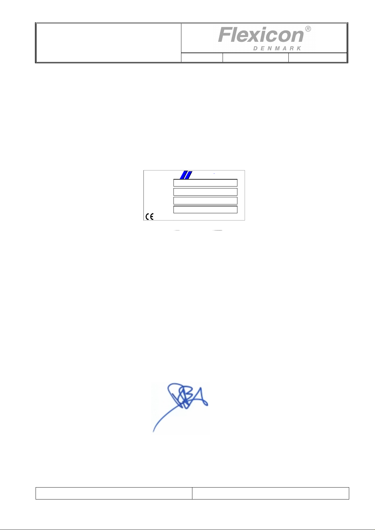
2 Declaration of conformi ty
We Flexicon A/S
Frejasvej 2-6
DK-4100 Ringsted
declare on our sole responsibility that the product:
Displacement Filler DF32
Flexicon a s
denmark
Model
Serial No.
Supply
Year
to which this declaration relates is in conformity with the following standard(s):
DS/EN ISO 12100 Safety of machinery - Basic concepts, general
principles of design
DS/EN 60204 Safety of machinery – Electrical equipment of
machines
according to the provisions in the Directives:
98/37/EC On the approximation of the laws of the Member
States relating to machinery.
73/23/EEC On the harmonization of the laws of Member
States relating to electrical equipment designed
for use within certain voltage limits
2004/108/EC On the approximation of the laws of the Member
States relating to electromagnetic compatibility
Signature
March 2007
Ringsted, Denmark
Flemming Jørgensen
DF32
“see label on product”
230V/50Hz/350W
2007
File:
DF32 OM 1.03 EN
Page 5
Operator’s manual
DF32
Rev.: 1.03 Date: 2007-03-12 Page 5 of 32
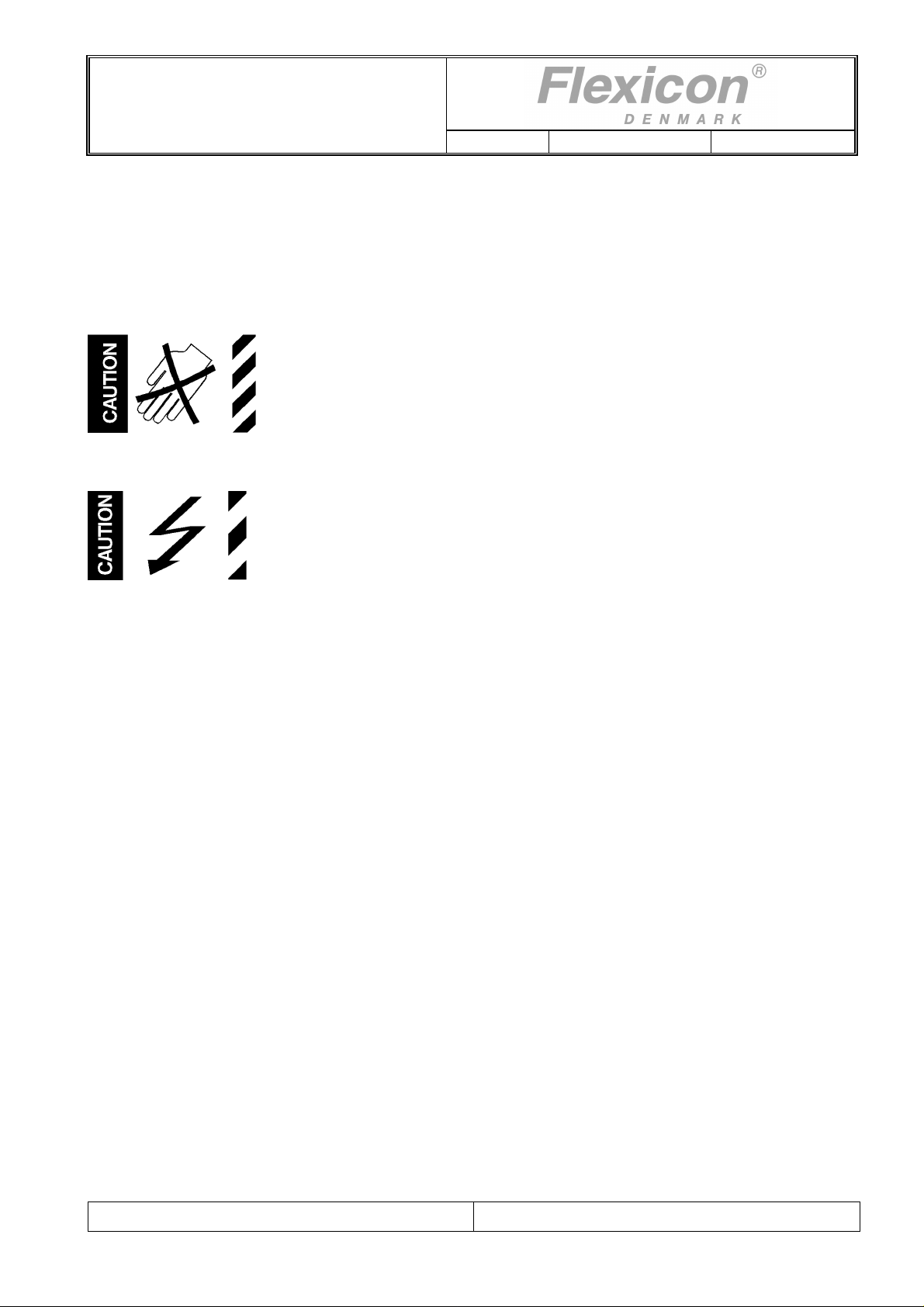
3 Caution
This manual should be read before using the DF32.
3.1 Explanations to the pictograms
Warning against touching/Warning against opening:
Warning against high voltage:
The DF32 should only be used for dosing and filling of viscous fluids.
The DF32 must be placed on a stable bed plate. It should not be exposed to great humidity, high
temperatures or other abnormal operating-environments.
When a hopper is mounted on DF32, the supplied support must be mounted under the pump head as
shown in section 7.3
It is not to be used in explosion hazardous environments.
It is prohibited to maintain or clean the DF32, when it is connected to the power supply.
It is prohibited for unauthorised personnel to open the cover of the DF32's electrical parts.
Always remember that the DF32 must be earthed by way of the switch.
Handle the filling needles with caution.
The mains switch is used for emergency stopping.
File:
DF32 OM 1.03 EN
Page 6

Operator’s manual
DF32
Rev.: 1.03 Date: 2007-03-12 Page 6 of 32
4 General information
4.1 Use
DF32 is a fully programmable, displacement filler (dispenser) which as a single unit can dispense
liquids of volumes from 10 ml up to more than 2500 ml.
DF32 has been specially developed for laboratory and small scale industrial applications where gentle
handling of product, absolute accuracy and minimum use of time for preparation of production are key
parameters.
DF32 is programmable for a number of different applications, and full production documentation can
be printed, if a printer is connected.
This manual contains all information necessary for the daily operation of the unit and so the DF32
manual should be read before using the filler.
4.2 Unpacking and inspection
Please check that all ordered items have been received and that no items were damaged during
transport. In case of any defects or omissions, please contact Flexicon A/S or your local supplier
immediately.
When ordering spare parts or accessories for the DF32, please state the serial number, which is
stamped on the label on the bottom of DF32.
ALWAYS REMEMBER that this machine must be earthed.
4.3 The pump head
DF32 operates with a positive displacement pump, which has a very low impact on the product.
The pump head is made of materials which are compatible with pharmaceutical products.
The materials used are stainless steel AISI 316 and plastic PEEK.
The displacement pump of the DF32 is not suitable for products containing particles.
File:
DF32 OM 1.03 EN
Page 7
Operator’s manual
DF32
Rev.: 1.03 Date: 2007-03-12 Page 7 of 32
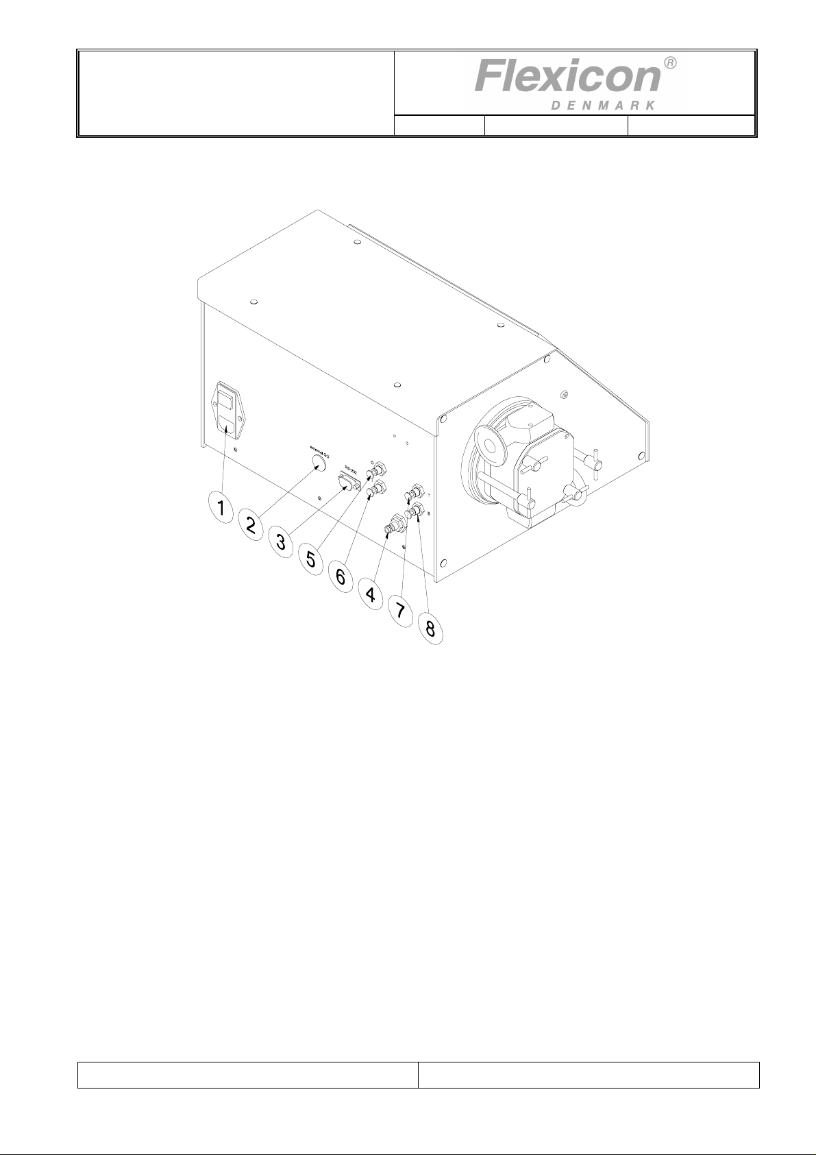
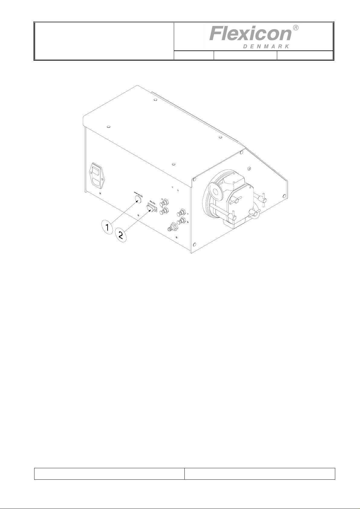
4.4 Installation
DF32 must be placed on a stable bed plate. All connections are on the rear of the machine.
Fig. 4.1
Electrical connections:
The main cable supplied is connected to the integrated main socket (1) in the main isolator, which also
1
contains master fuses. The plug is connected to an earthed switch.
2 External GO plug for the connection of a foot switch or for an external starting signal.
3 RS-232 plug for printer connection.
Connections of pneumatics:
4 If DF32 is to run with pneumatic equipment, a supply of compressed and dry air should be connected to
the quick release clutch (4).
The female part of the quick release clutch is supplied with the machine, but is not fitted.
Filling nozzles with pneumatic cut-off valves:
5 Nozzles with internal cut-off valve shall be connected to connector 5.
6 Nozzles with external cut-off valve shall be connected to connector 6.
Pneumatically driven diving nozzles:
7 Hoses giving the downward movement should be connected to connector 7,
8 Hoses giving the upward movement should be connected to connector 8.
File:
DF32 OM 1.03 EN
Page 8
Operator’s manual
DF32
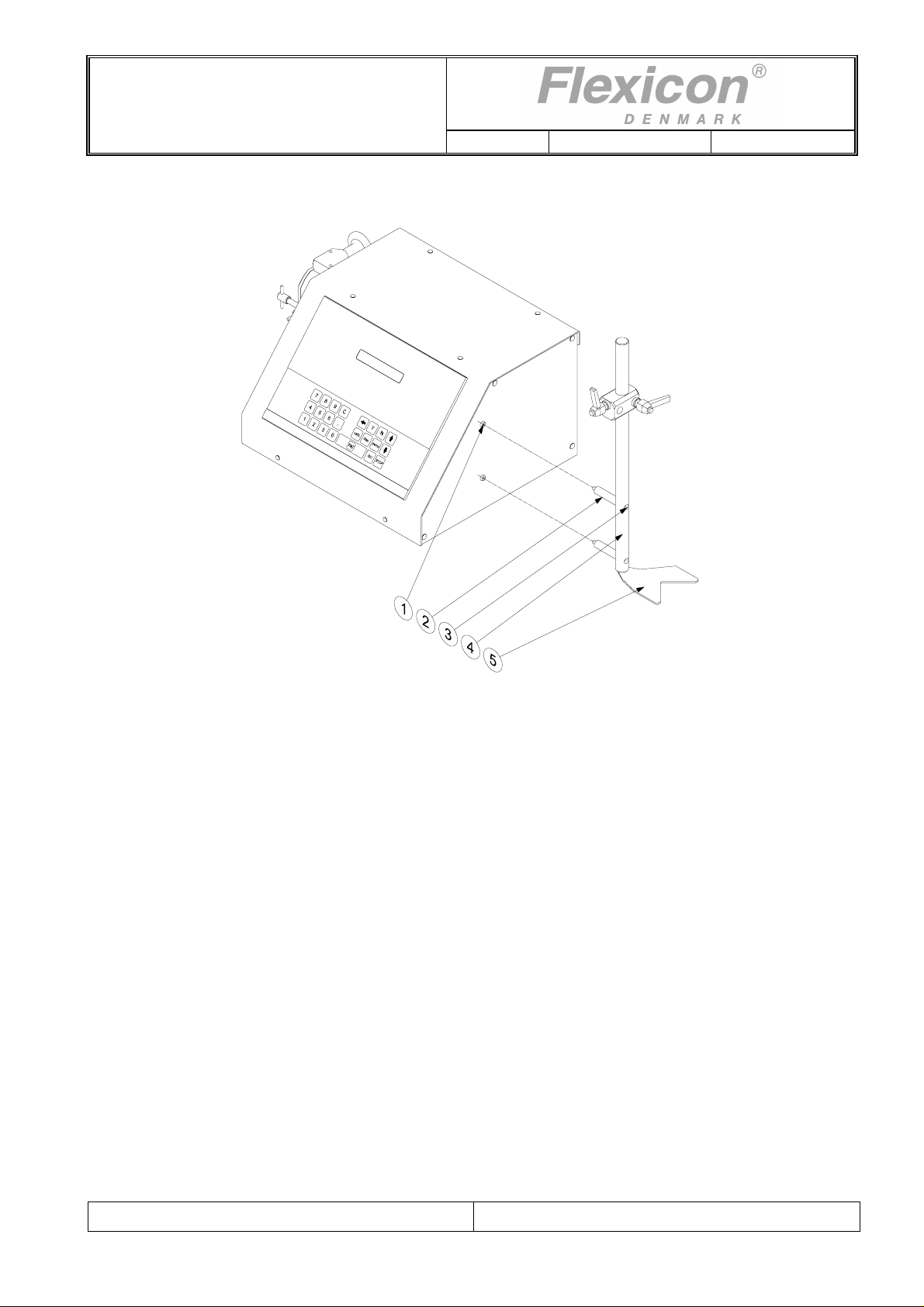
4.5 Fitting of filling stand
Rev.: 1.03 Date: 2007-03-12 Page 8 of 32
Fig. 4.2
The filling stand can be fitted to both ends of DF32.
First remove the s cre ws (1)
Now you are able to fit the filling stand (4) by using the supplied distance tubes (2) and the screws (3).
The bottle guide (5) can be turned upside / down for adjusting to low or high bottles or containers.
DF32 is now ready to be switched on and to be programmed.
File:
DF32 OM 1.03 EN
Page 9
Operator’s manual
DF32
5 Control
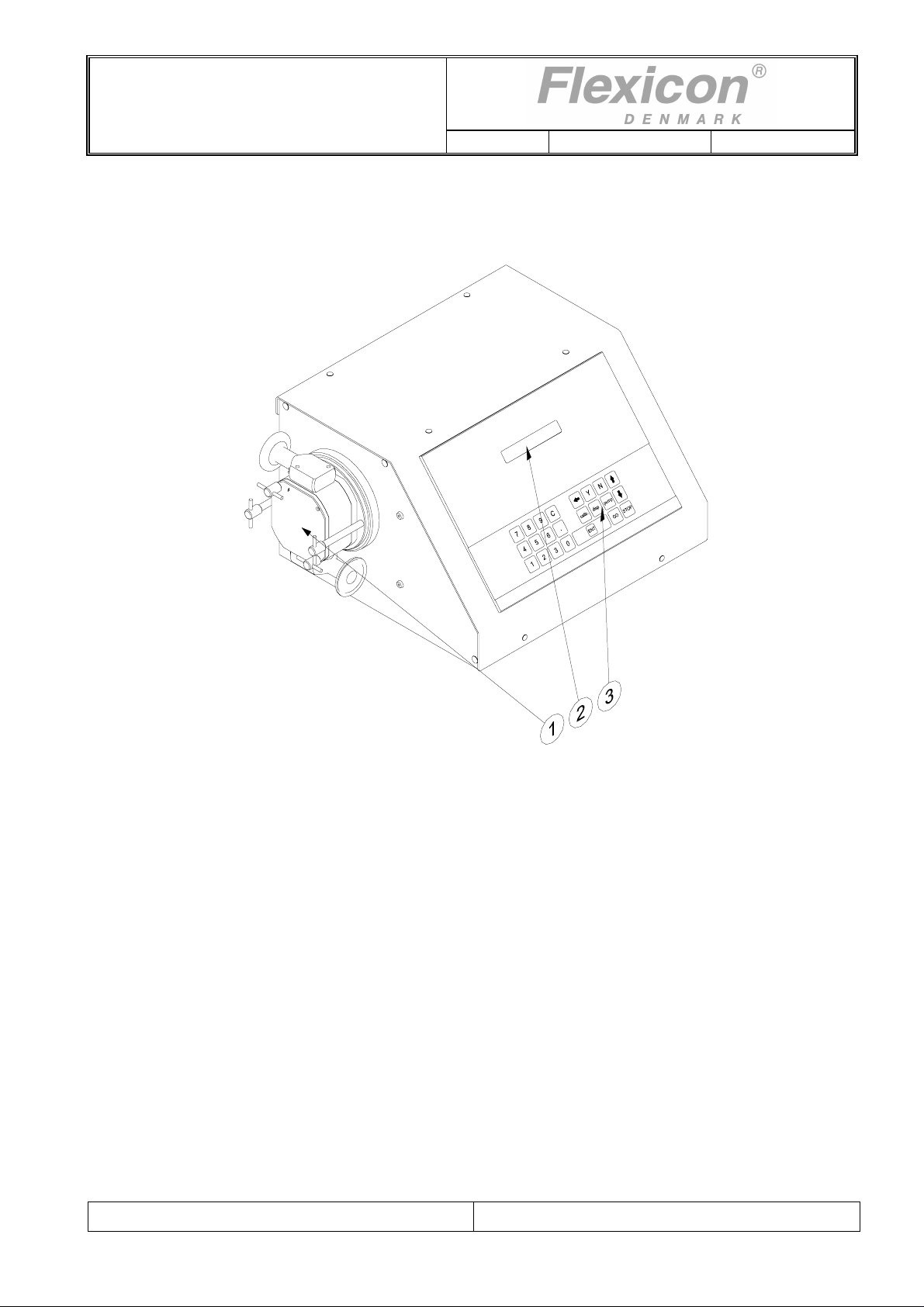
5.1 Filler lay-out
Rev.: 1.03 Date: 2007-03-12 Page 9 of 32
Fig. 5.1
1 Dispenser head
2 Display
3 Membrane-type keyboard
5.2 Dispenser head
The dispenser head can be equipped with connectors for different tube dimensions or a hopper for
product intake. For product dispensing the dispenser head can be equipped with connectors for
different tube dimensions.
The dispenser head is fitted with a safety system which prevents starting of the machine without the
head mounted on the machine.
File:
DF32 OM 1.03 EN
Page 10

Operator’s manual
DF32
Rev.: 1.03 Date: 2007-03-12 Page 10 of 32
5.3 Display
FUNCTION NO.:
F 1: VOLUME (ml): 100.00
Fig. 5.2
The display of DF32 consists of 2 lines of 24 characters each and has constant background lighting.
There will always be a blinking cursor on the display, which indicates where a character will appear, if
a key is activated.
The top line is the prompt line where DF32 communicates with the operator.
The bottom line is the status line that always shows the current operating parameters. This status line
can be scrolled by pressing the UP or DOWN ARROW of the keyboard.
When operating DF32, it is VERY important to watch the top line constantly, as any current question
or instruction will be displayed here.
File:
DF32 OM 1.03 EN
Page 11

Operator’s manual
DF32
Rev.: 1.03 Date: 2007-03-12 Page 11 of 32
5.4 Keyboard
It is a foil-type keyboard with built-in click. The keyboard is quite tight and plane and can be cleaned
with alcohol and other detergents.
7
8
9
C
4
5
6
1
2
3
7
8
9
C
4
5
6
1
2
3
Numerical keys 0 to 9 as well as decimal point.
.
0
.
0
calib.Ydisp.
ENT
N
pump
STOPGO
C
Y
N
disp.
pump
calib.
GO
“C” : Cancel
Delete Character to the left of the cursor
Scroll the status line one line up
Scroll the status line one line down
YES key for YES/NO questions on display
NO key for YES/NO questions on display
Activates filling
Activates continuous pumping
Activates calibration
Start Button
STOP
ENT
Fig. 5.3
File:
DF32 OM 1.03 EN
Stop Button
Enter / return to enter values typed on the keyboard.
Page 12
Operator’s manual
DF32
Rev.: 1.03 Date: 2007-03-12 Page 12 of 32
6 Programming
6.1 Starting DF32
When turning on the main switch, the display will show the following:
DF32 V1.1 (C) Flexicon’ 00
PRESS GO TO CONTINUE
Fig. 6.1
Press the <GO> key and the display will show the following:
FUNCTION NO.:
F 1: VOLUME (ml): 100.00
Fig. 6.2
The value shown in the status line will be the above or the last value used.
DF32 is now ready to be programmed.
6.2 Parameters
In the following, a parameter will be the value of a single function, for instance volume, velocity or
number of fills.
6.3 Programs
In the following descriptions, a program will be a complete set of parameters which together will
constitute the DF32 work instructions.
6.4 General information on the programming of DF32
DF32 is equipped with a battery in the memory and will therefore always remember the programmed
parameters, even if the main isolator is turned off.
The programming is done using functions, i.e. every operating parameter has its own function
number.
The programming is carried out by entering the function number followed by "ENT".
This will make the required function appear in the prompt line of the display and show the current
value or information of the function.
This value will automatically be overwritten when entering a new value.
After being entered, the new value will be shown in the prompt line. The new value is entered into the
computer by pressing "ENT".
The new value will be shown in the status line at once.
Example:
If a volume of 8.5 ml is required, the following must be entered:
<1>+<ENT>+<8>+<.>+<5>+<ENT>
File:
DF32 OM 1.03 EN
Page 13

Operator’s manual
DF32
Rev.: 1.03 Date: 2007-03-12 Page 13 of 32
6.5 List of functions
1. Volume 21. Batch number
3. Velocity 24. Print status
4. Acceleration/deceleration 29. Print parameters
5. Reversing (back suction) 31. Save program
6. Batch size 32. Load program
7. Delay 33. Delete program
8. Completed fills 34. Print programs
9. Specific gravity 46. Set language
10. Filling rate 47. Printer set-up
15. Input mode 72. Volume format
18. Timer 2 80. Reset memory
20. Operator number
6.6 Description of functions
The individual functions will be described in the following:
1. Volume
Value: Choice of ml and grams.
Required volume from 0.01 to 9999.9 ml.
3. Velocity
Value: Revolutions per minute (rpm).
Enter the required velocity.
Min.: 30 rpm.
Max.: 500 rpm.
4. Acceleration/deceleration
Value: An integral number.
The filling can start and stop more or less abruptly.
This function offers a choice of values between 1 and 100.
1 = slowest acceleration.
100 = fastest acceleration.
5. Reversing (back suction)
Value: An integral number.
When the filling stops, the filler can be asked to produce a minor back suction to prevent dripping.
The back suction can be set at values between 0 and 10.
0 = no back suction.
10 = maximum back suction.
File:
DF32 OM 1.03 EN
Page 14

Operator’s manual
DF32
Rev.: 1.03 Date: 2007-03-12 Page 14 of 32
6. Batch size
Value: Number.
Enter the number of fills you want the filler to perform when started by <GO>, foot switch or via
electrical signal. Any number of fills between 1 and 65,000 can be selected.
When the filler is operating in automatic system, where the system itself starts the filler each time a
bottle is in position, THE VALUE IN THIS FUNCTION MUST ALWAYS BE 1.
7. Delay
Value: Seconds.
If more than one fill is chosen in function 6, enter the required delay between the fills.
The value of the delay can range between 0.1 - 25.0 seconds, with a graduation of 0.1 second.
8. Completed fills
Value: Number.
Nothing can be entered in this function since it only displays the number of fills completed since the
latest reset of the function.
To reset this function, press the <C> key.
9. Specific gravity
Value: Decimal number.
Enter the specific gravity of the liquid in g/ml if the required volume was entered in function 1,
and if this volume is controlled by balance.
10. Filling rate
Value: Number of fills per minute.
Nothing can be entered in this function, since it only displays the current filling rate.
15. Input mode
Value: 1 or 2.
1 = The foot switch will only function as a starter.
2 = First press on the foot switch starts the filler.
Second press on the foot switch stops the filler.
Third press on the foot switch starts the filler.
18. Timer 2
Value: Seconds
Range: 0.0 to 25.5 seconds.
If the filler operates with a pneumatic diving nozzle, can a delay be set between the starting signal
and the time the pump actually starts.
20. Operator number
An operator number of up to 10 digits can be entered in this function.
This operator number will appear on print-outs.
21. Batch number
A batch number of up to 10 digits can be entered in this function.
This batch number will appear on print-outs.
File:
DF32 OM 1.03 EN
Page 15

Operator’s manual
DF32
Rev.: 1.03 Date: 2007-03-12 Page 15 of 32
24. Print status
If a printer is connected, this function will start the printing of the current production status.
29. Print parameters
This function prints the current parameters via the connected printer.
31. Save program
Saves a complete set of parameters as a program.
It is possible to save up to 5 sets of parameters in the memory.
32. Load program
Loads a previously saved program and overwrites the current parameters with the values of t he
loaded program.
33. Delete program
This function will delete the required program.
34. Print programs
This function prints the individual parameters in all the programs stored in the memory.
46. Select language
Value: An integral number.
This version offers a choice of 2 languages.
1 - English
2 - German
The languages will be active on the display and on the print-outs.
47. Printer set-up
Function 47 tells the system which protocol to use when transmitting to connected printer.
When this function is activated, it will first require the operator to enter the transmission velocity. One
of the following values must be chosen:
75 110 134 150 300 600 1200 1800 2000 2400 4800 9600
Subsequently DF32 will ask the operator to enter a protocol number. There is a choice between the
following protocols:
1 : 7 data bits 1 stop bit no parity
2 : 7 data bits 1 stop bit even parity
3 : 7 data bits 1 stop bit uneven parity
4 : 7 data bits 2 stop bits no parity
5 : 7 data bits 2 stop bits even parity
6 : 7 data bits 2 stop bits uneven parity
7 : 8 data bits 1 stop bit no parity
8 : 8 data bits 1 stop bit even parity
9 : 8 data bits 1 stop bit uneven parity
10 : 8 data bits 2 stop bits no parity
11 : 8 data bits 2 stop bits even parity
12 : 8 data bits 2 stop bits uneven parity
Fig. 6.3
File:
DF32 OM 1.03 EN
Page 16

Operator’s manual
DF32
Rev.: 1.03 Date: 2007-03-12 Page 16 of 32
72. Volume format
This function sets the unit for volume. If the value 1 is chosen then the volume unit is set to ml and if
value 2 is chosen then the volume unit is set to gram. The unit ml or gram is shown in F1 and log print
outs.
80. Reset memory
This function will reset the memory with the exception of the part used for saving programs.
DF32 will pass into stand-by, and when switched on again the built-in parameters will be valid.
IF DF32 DOES NOT WORK OR DOES NOT OPERATE AS EXPECTED –
ACTIVATE FUNCTION 80.
File:
DF32 OM 1.03 EN
Page 17

Operator’s manual
DF32
7 Daily use
7.1 Choice of product connections
Rev.: 1.03 Date: 2007-03-12 Page 17 of 32
Fig. 7.1
For product intake either a hose connector (1) or a hopper (6) can be
used.
The higher viscosity of the product, the larger diameter of suction hose
should be used.
For high viscosity products or sticky products, the hopper should be
chosen for good product flow towards the pump.
Hose ID Flexicon Part no.
½ “ 84-080-125
¾ “ 84-080-190
1 “ 84-080-250
1½ “ 84-080-380
Hopper
15 litres
88-350-010
When using hose for product intake, the pump head normally should be mounted with the straight
connector (7) facing down (left drawing Fig. 7.1).
If the product container is situated above the pump head, the pump head could be mounted with the
straight connector facing up, or an angled connector could be chosen, in order to have a straight
product path.
When using hopper for product intake, the pump head should be mounted with the straight connector
facing up (right drawing Fig. 7.1).
The arrow on the pump head will show the direction of product flow.
NOTE: The following items are included with the DF32 filler:
Position no Quantities Description
Item 1 1 pcs Hose connector ½”
Item 1 1 pcs Hose connector 1”
Item 2 2 pcs Clamp ring
Item 3 2 pcs Clamp seal (Nitril rubber)
Item 4 1 pcs Angled connector
File:
DF32 OM 1.03 EN
Page 18

Operator’s manual
DF32
Rev.: 1.03 Date: 2007-03-12 Page 18 of 32
Position no Quantities Description
Item 5 2 pcs O-ring (Viton)
Item 7 1 pcs Straight connector
7.2 “Step-by-step” assembly of pump head
Fig. 7.2
Step Action
1
2 Mount the O-ring (12) on the rear part.
3
4
5 Place the shaft assembly in the rear part.
6
7 Mount the driving hub (9) on the shaft.
8 Mount the impeller plates (10) into the grooves of the driving hub.
File:
DF32 OM 1.03 EN
Place the rear part (1) with the curved rim facing upwards.
The centre hole should be placed above a hole or a groove with a depth of 5 cm.
If the ceramic ring (16) and the O-ring (17) have been removed from the rear part, they must be
mounted again. The O-ring first, and then the ceramic ring.
Use the supplied tool when mounting (and dismounting) the ceramic ring.
Note: The chamfered edge on the ceramic ring must face the rear side of the pump.
Mount the O-ring (7) on the bearing (6), and place both on the shaft (8).
Then put the wave spring (20) on the shaft.
Mount the Quad seal (19) into the sealing ring (18), and place both on the shaft, make sure that
the flat face in the sealing ring matched the corresponding face on the shaft.
Fit the pump housing (2) to the rear part. The longer pin on the pump housing should be fitted into
the hole in the rear part. This indicates correct positioning.
Page 19

Operator’s manual
DF32
Rev.: 1.03 Date: 2007-03-12 Page 19 of 32
Step Action
9 Mount the O-ring (12) to the front part (5).
10 Mount the O-ring (7) on the bearing (11), and mount both in the front part.
11
12
Fit the front part to the pump housing.
A pin on the pump housing and a hole in the front part indicates correct positioning.
Close the pump head by fastening the finger screws (21) firmly.
Note: If the front part is angled during fastening, the pump might not be leak tight.
7.3 Fitting the pump head to the machine
Fig. 7.3
Step Action
1 Hold the pump head (2), with the arrow pointing in the desired direction of flow.
Align the key (1) on the drive shaft, with the groove on the pump head shaft.
2
3 Fasten the pump head with the 2 finger screws (3).
4 Set up DF32 with product tubes and filling nozzles.
Press the pump head towards the flange on the machine front, and make sure that the pin on the
rear of the pump head fits into the corresponding hole in the flange.
NOTE!
When a hopper is used for product supplied, the pump head of DF32 must be supported by the
supplied support, for safety reasons. See Fig. 7.4
File:
DF32 OM 1.03 EN
Page 20

Operator’s manual
DF32
Rev.: 1.03 Date: 2007-03-12 Page 20 of 32
Hopper
The s upport is fixed by
use of 2 screws.
M4 x 35.
The support must be
resting on the surface
that DF32 stands on.
Fig. 7.4
7.4 Used as a filler
Switch on DF32 and press <GO>.
Example of filling job:
Volume: 50 ml
Velocity: 250 rpm
Acceleration: 35
Small back suction.
100 fills to be completed
A delay of 1.1 seconds between the fills.
Product with specific gravity of 1.0
The above job is to be programmed as follows:
The above job is programmed:
Volume: <1>+<ENT>+<5>+<0>+<ENT>
Velocity: <3>+<ENT>+<2>+<5>+<0>+<ENT>
Acceleration: <4>+<ENT>+<3>+<5>+<ENT>
Back suction: <5>+<ENT>+<1>+<ENT>
Number of fills: <6> +< ENT>+<1>+<0>+<0>+<ENT>
Delay: <7>+<ENT>+<1>+<.>+<1>+<ENT>
Specific Gravity <9>+<ENT>+<1>+<.>+<0>+<ENT>
You have now programmed the DF32 for the job, but want to reset the built- in counters. In function 8
the counters indicate "number of completed fills".
Number of fills: <8>+<ENT>+<C>+<ENT>
Now inform DF32 that you want to enter filling mode by pressing <disp.>.
Every time <GO> or the foot switch is pressed, or every time an electric signal is given, DF32 will run
100 fills of 8.5 ml with a delay of 1.1 seconds between the fills.
Press <GO>, verify that DF32 starts and let it run.
Press ARROW DOWN until you see function 8 on the status line and that F8: is counting each fill.
File:
DF32 OM 1.03 EN
Page 21

Operator’s manual
DF32
Rev.: 1.03 Date: 2007-03-12 Page 21 of 32
F10: gives a current indication of the number of fills completed per minute.
The fills have not been calibrated. For this function, please see chapter 5 of this manual.
7.5 Stop filling
When DF32 has completed the number of fills asked for in DF32: it will stop automatically.
If <GO> is pressed again, DF32 will complete the programmed number of fills once more.
If you want to stop the filling before the programmed number has been completed, press <STOP>,
and DF32 will stop after completing the filling in progress.
The filling series can be completed by pressing <GO>.
If you want to stop IMMEDIATELY, such as in the middle of a fill, press <STOP> twice, and DF32 will
stop immediately.
The filling series can be completed by pressing <disp.>+<GO>, and the interrupted filling will be
included.
7.6 Used as a pump
DF32 can also be used as a pump.
In this case only tube diameter and velocity should be entered.
Start the pumping by pressing <pump>+<GO>.
DF32 will start with the entered acceleration and run up to the required number of revolutions per
minute.
DF32 will pump at this velocity until stopped by pressing <STOP>.
7.7 Used with a bottle handling system
DF32 can also be used together with a bottle handling system like FlexFeed 20 from Flexicon.
When DF32 is integrated in an automatic bottle handling system, it is important to observe the
following:
The batch size in case of running with a bottle handling system must be set to 1.
The DF32 should be in dispense mode before starting the fill sequence.
The Go signal which activates filling should be generated by the bottle handling system.
The Go signal should be inserted into DF32 via External Go port.
For information on External Go port, please refer to section 10.
File:
DF32 OM 1.03 EN
Page 22

Operator’s manual
DF32
Rev.: 1.03 Date: 2007-03-12 Page 22 of 32
8 Calibration
As the surroundings of the DF32 may vary from time to time and as pump head and products have
small tolerances, it is necessary to calibrate the filler when it is started.
If the quantity has been entered as volume in ml, a measuring cylinder or a balance may be used as a
control and measuring unit. The balance will always be the more accurate, especially for small
quantities.
The calibration in DF32 is made as following.
This re-calibration can be carried out simultaneously with the fills.
! The DF32 should always be re-calibrated after changing any of the pump parameters:
That is: Volume, Velocity, Acceleration or Reversing!
8.1 Volume calibr ation with measurin g cylinder
IF A VOLUME HAS BEEN ENTERED IN FUNCTION 1, AND A COMPLETED FILL IS MEASURED
IN A MEASURING CYLINDER,
THE SPECIFIC GRAVITY IN FUNCTION 9 MUST ALWAYS BE SET AT THE VALUE 1.0.
The parameters already entered may be used for a trial.
Prepare the measuring cylinder and make sure that the tubes are completely filled, up to and
including the filling needle.
It is recommended to let the filler complete a few fills before the calibration is carried out.
Keep the measuring cylinder below the filling needle and press <calib>+<GO> to complete a single fill
and DF32 will now ask the dispensed volume showing the following display:
CALIB. WEIGHT: 0.0000_
F 1: VOLUME (ml): 50.0
Fig. 8.1
In the prompt line, DF32 prompts for the weight. THE WEIGHT MUST BE ENTERED, i.e. 48.5:
<4>+<8>+<.>+<5>+<ENT>.
DF32 has now automatically adjusted from 48.5 ml to 50.0 ml.
Function 8 should now be reset, and the filling may be started by pressing <disp.>+<GO>.
File:
DF32 OM 1.03 EN
Page 23

Operator’s manual
DF32
Rev.: 1.03 Date: 2007-03-12 Page 23 of 32
8.2 Volume calibr ation with balance
IF A VOLUME HAS BEEN ENTERED IN FUNCTION 1, AND A COMPLETED FILL IS MEASURED
WITH A BALANCE,
THE SPECIFIC GRAVITY OF THE LIQUID IN QUESTION IS TO BE ENTERED IN FUNCTION 9.
The parameters already entered may be used for a trial.
Prepare the balance by tarring the container and make sure that the tubes are completely filled, up to
and including the filling needle.
It is recommended to let the filler complete a few fills before the calibration is carried out.
Keep the tarred container below the filling needle and complete a single fill by pressing
<calib>+<GO> and DF32 will now ask for the completed volume showing the following display:
CALIB. WEIGHT: 0.0000_
F 1: VOLUME (ml): 50.0
Fig. 8.2
In the prompt line, DF32 asks the weight, and the WEIGHT of the trial fill in question must be entered,
i.e. 46.8: <4>+< 6>+<.>+<8>+<ENT>
DF32 has now automatically adjusted from 46.8 g to 50.0 ml.
Function 8 should now be reset, and the filling may be started by pressing <disp.>+<GO>.
8.3 Re-calibration
During production it may be necessary to recalibrate the volume dispensed by the filler to compensate
for changes in the environment e.g. the liquid level of the feed vessel will sink. This re-calibration may
be carried out without stopping the filling.
IT IS IMPORTANT TO USE THE SAME MEASURING METHOD FOR THE RECALIBRATION AS
USED FOR THE INITIAL CAL IBRATION.
Draw off a filled sample and measure it. Subsequently, the procedure is the same as used when
starting the filling series.
DF32 will now automatically adjust the subsequent fills.
File:
DF32 OM 1.03 EN
Page 24

Operator’s manual
DF32
Rev.: 1.03 Date: 2007-03-12 Page 24 of 32
9 Print-out
DF32 can be connected to a printer (via RS-232) which can produce three different types of printouts.
9.1 Print current parameters
Function 29 prints the current parameters, and print-outs should be made after programming and
calibrating DF32 and resetting function 8.
The print-out is started in the following way:
<2>+<9>+<ENT>, and the following display will be shown:
F29 PRN PARAM (Y/N):_
F 1: VOLUME (ml): 50.0
Fig. 9.1
Press the <Y> key to confirm start of printing, and the printer will start.
Example of print-out:
* Flexicon DF32 V1.1 *
OPERATOR 2641
BATCH NO. 9604084438
VOLUME (ml) 50.0
VELOCITY (rpm) 400
ACCELERATION 35
REVERSE 1
BATCH SIZE 100
DELAY (sec) 1.1
SPECIFIC GRAVITY (g/ml) 1.0000
NUMBER OF FILLS 0
Fig. 9.2
File:
DF32 OM 1.03 EN
Page 25

Operator’s manual
DF32
Rev.: 1.03 Date: 2007-03-12 Page 25 of 32
9.2 Print current status
Function 24 prints the current parameters, and print-outs should be made after completion of the
filling series.
The printing is to be started in the following way:
<2>+<4>+<ENT>, and the following display will be shown:
F24 PRN STATUS (Y/N):_
F 1: VOLUME (ml): 50.0
Fig. 9.3
Press the <Y> key to confirm start of printing, and the printer will start.
Example of print-out:
* Flexicon DF32 V1.1 *
OPERATOR 2641
BATCH NO. 9604084438
VOLUME (ml) 50.0
FILLS PER MIN 17
NUMBER OF FILLS 100
AT FILL NO: 51
RECALIB VOL (ml): 48.7
AT FILL NO: 74
RECALIB VOL (ml): 47.9
Fig. 9.4
In addition to registering the filling series, DF32 also registers when and from which value
recalibrations were carried out.
If the print-out of the current parameters is left in the printer till the status print-out has been made,
this will give a full production documentation which might look like the one shown overleaf.
File:
DF32 OM 1.03 EN
Page 26

Operator’s manual
DF32
Rev.: 1.03 Date: 2007-03-12 Page 26 of 32
* Flexicon DF32 V1.1 *
OPERATOR 2641
BATCH NO. 9604084438
VOLUME (ml) 50.0
VELOCITY (rpm) 250
ACCELERATION 35
REVERSE 1
BATCH SIZE 100
DELAY (sec) 1.1
SPECIFIC GRAVITY (g/ml) 1.0000
NUMBER OF FILLS 0
* Flexicon DF32 V1.1 *
OPERATOR 2641
BATCH NO. 9604084438
VOLUME (ml) 50.0
FILLS PER MIN 17
NUMBER OF FILLS 100
AT FILL NO: 51
RECALIB VOL (ml): 48.7
AT FILL NO: 74
RECALIB VOL (ml): 47.9
Fig. 9.5
After the status print-out the printer memory is deleted automatically.
File:
DF32 OM 1.03 EN
Page 27

Operator’s manual
DF32
Rev.: 1.03 Date: 2007-03-12 Page 27 of 32
9.3 Print programs
Up to five programs can be stored in DF32, and a list of saved programs can be printed by means of
function 34.
The printing is to be started in the following way:
<3>+<4>+<ENT>, and the following display will be shown:
F34 PRINT PROGS (Y/N):_
F 1: VOLUME (ml): 50.0
Fig. 9.6
Press the <Y> key to confirm start of printing, and the printer will start.
Example of print-out:
* Flexicon DF32 V1.1 *
PROGRAM NO. 1
VOLUME (ml) 50.0
VELOCITY(rpm) 250
ACCELERATION 35
REVERSE 1
BATCH SIZE 100
DELAY (sec) 1.1
SPECIFIC GRAVITY (g/ml) 1.0000
PROGRAM NO. 2
VOLUME (ml) 25.0
Velocity(rpm) 300
ACCELERATION 28
REVERSE 0
BATCH SIZE 500
DELAY (sec) 1.0
SPECIFIC GRAVITY (g/ml) 1.0100
Fig. 9.7
File:
DF32 OM 1.03 EN
Page 28
Operator’s manual
DF32
10 Interface
Rev.: 1.03 Date: 2007-03-12 Page 28 of 32
Fig. 10.1
DF32 has two electrical interface connectors.
(1) "External GO"
(2) RS-232
"External GO" is designed as a 5-pin DIN plug with the following PIN configuration:
PIN 1 Input for start signal. +5 - 50 VDC, min. 100 msec. positive edge-
triggered.
PIN 2:
PIN 3:
PIN 4: Status output, max. +24 VDC, 100 mA.
PIN 5: Status output, max. + 24 VDC, 100 mA.
Output, +24 VDC, max. 250 mA.
Ground
Pin 4 is grounded via an open collector during filling.
Pin 5 is complementary to Pin 4.
File:
DF32 OM 1.03 EN
Page 29
Operator’s manual
DF32
10.1 RS-232
RS-232 has a 9-pin SUB-D plug.
PIN 1 No connection
PIN 2 Receive data
PIN 3: Transmit data
PIN 4: +12 VDC (at 1 kOhm)
PIN 5: Ground
PIN 6: No connection
PIN 7: Request to send
PIN 8: Clear to send
PIN 9 No connection
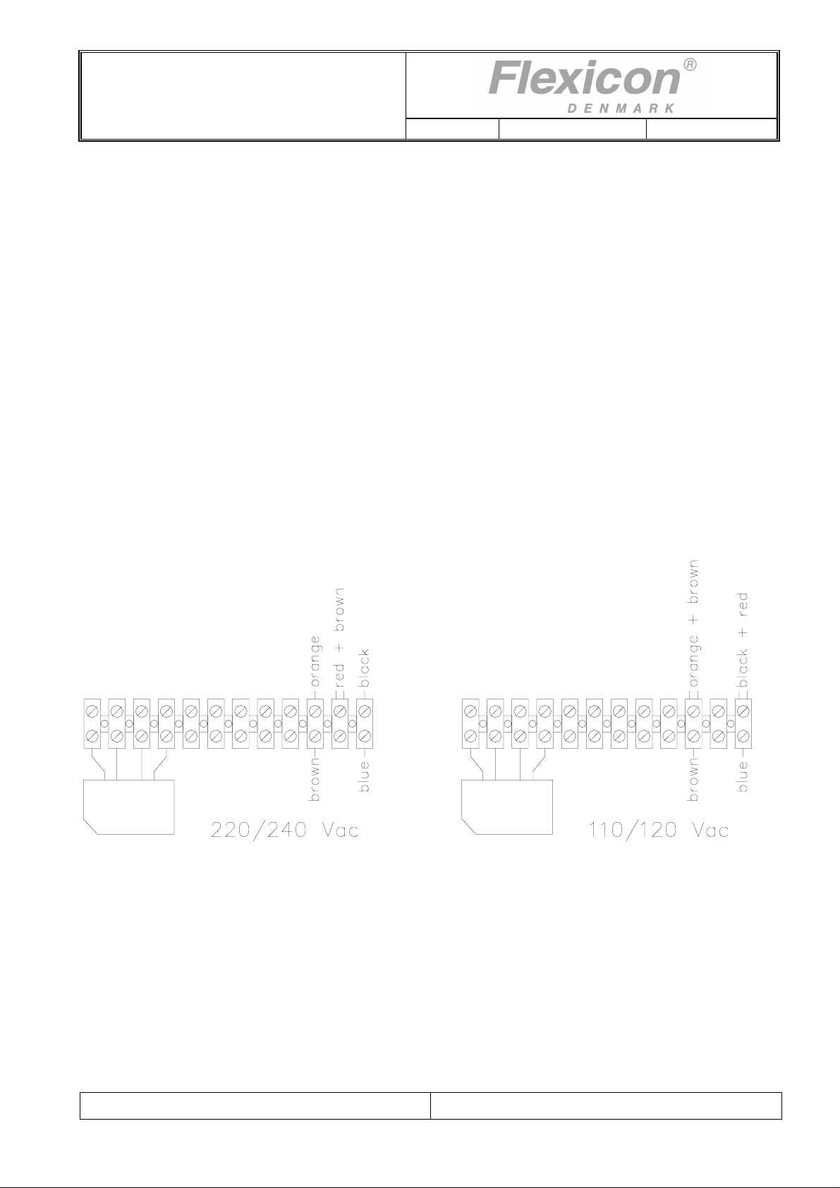
10.2 Change of main power
Rev.: 1.03 Date: 2007-03-12 Page 29 of 32
Fig. 10.2
DF32 can be switched between two different main power supply voltages.
The change over is carried out inside the machine by moving the wires to the positions indicated in
Fig. 10.2.
File:
DF32 OM 1.03 EN
Page 30
Operator’s manual
DF32
Rev.: 1.03 Date: 2007-03-12 Page 30 of 32
11 Cleaning and maintenance
11.1 Daily cleaning
11.1.1 Cabinet
As the cabinet of DF32 is not in direct contact with the dispensed product, daily cleaning will not be
necessary except for the normal routine cleaning of production equipment.
When cleaning, please note that the cabinet of DF32 is not provided with sealing, and is to be
considered as open. Therefore, liquids are NOT to be splashed onto DF32.
It may only be cleaned with a damp piece of paper towel or a cloth.
The cabinet is made of anodized aluminum and stainless steel, and normal detergents as spirit and
isopropanol may be used.
11.1.2 Pump head
As the pump head is intended for direct contact with the dispensed product it is made of materials,
which can be washed in hot water with detergents. The components can all be autoclaved for sterility.
NOTE! The pump head must be dismantled while autoclaved.
11.2 Sterilization
If DF32 is placed in an aseptic environment, the sterilisation may be made as described in section
11.1, or you may sterilise DF32 by gases observing the following precautions.
If you use gasses that might injure and corrode contacts and other metals, air slots and sockets
MUST be covered with tape.
11.3 Maintenance
As all movable parts in DF32 are maintenance-free, no maintenance is required apart from normal
cleaning of the equipment.
If service should be needed, please contact your supplier or Flexicon A/S.
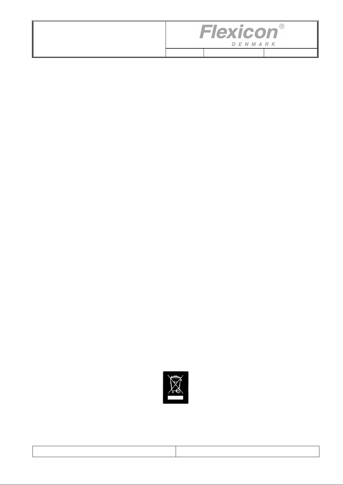
11.4 Disposal of electrical components
Flexicon machines may not be disposed using normal refuse collection. The machines must be
collected and disposed separately as they contain electrical components such as batteries, electrolyte
capacitors, liquid crystal displays and printed circuit boards. Further information is available on our
web-site www.flexicon.dk.
File:
DF32 OM 1.03 EN
Page 31

Operator’s manual
DF32
Rev.: 1.03 Date: 2007-03-12 Page 31 of 32
11.5 Accessories and spare parts
11.5.1 Accessories
Spare part no. Description
88-350-010 HOPPER 15L
84-080-125 CONNECTOR FOR 1 TUBE 12,5 ID/1CLAMP
84-080-190 CONNECTOR FOR 1 TUBE 19.0 ID/1"CLAMP
84-080-250 CONNECTOR FOR 1 TUBE 19.0 ID/1"CLAMP
84-080-380 CONNECTOR F. 1 TUBE 38.0 ID/1"CLAMP
84-100-050 ARMED PVC TUBING 1/2"
84-100-075 ARMED PVC TUBING 3/4"
84-100-100 ARMED PVC TUBING 1"
84-100-250 ARMED PVC VACUUM TUBING 1 1/2"
52-460-600 TUBE CLAMP FOR 1/2' TUBE, 13X20MM
52-460-800 TUBE CLAMP FOR 1' TUBE, 22-32MM
52-460-900 TUBE CLAMP FOR 1½" TUBE
11.5.2 Spare parts
Spare part no. Description
32-400-051 PADDLE
32-400-056 RING FOR SHAFT SEAL
84-085-220 CLAMP SEAL
84-085-230 CLAMP GASKET W. 1" BORE, SILICONE
54-021-120 O-RING, VITON, Ø75X2,5
File:
DF32 OM 1.03 EN
Page 32

Operator’s manual
DF32
Rev.: 1.03 Date: 2007-03-12 Page 32 of 32
12 AnnexA
Sound pressure level: LAeq < 70 dB(a)
COPYRIGHT
*********
Copyright (c) 2007 Flexicon A/S. All rights to this manual belong to Flexicon A/S. Neither the complete
manual nor parts of it may be translated, copied, printed or published in any form or by any means
without permission in writing from Flexicon A/S
Flexicon A/S is convinced that the information of this manual is correct, but Flexicon A/S can not be
held responsible for it.
Flexicon A/S reserves the right to update and amend this manual without previous notice. Flexicon
A/S is under no obligation to update manuals already published.
File:
DF32 OM 1.03 EN
 Loading...