

Page 1

Disc
The disc inserted in the front cover contains the user manual of the models Bredel 40,
Bredel 50, Bredel 65, Bredel 80 and Bredel 100. The user manual is available in the
following languages:
The disc also contains quick-reference instructions for the replacement of the pump
hose. This replacement instruction is only for users that are familiar with the
replacement procedures in the user manual.
How to use the disc
1 Put the disc in the disc drive.
2 Close the disc drive.
The disc will start automatically.
3 Wait until the various language versions appear on screen.
4 Select the required language (click 1x with the left mouse button).
The PDF reader program will automatically start and the required user manual
appears on screen.
Shortcuts
In the left margin you will find the various chapters and paragraphs. These can be
accessed directly by clicking on the required chapter or paragraph.
In the text you will find hyperlink s to chapter s or para graphs . These hy perli nks are li nked
with the required chapters or paragraphs. By clicking a shortcut the required chapter or
paragraph appears on screen.
System requirements
The program on the disc requires a PC with the following minimum system
requirements:
• Disc drive
The following software must be installed on the PC:
• PDF reader program
• An Internet browser
1
Page 2

2
Page 3
Hose pump series
Bredel 40, Bredel 50, Bredel 65, Bredel 80 and
Bredel 100
Manual
3
Page 4

© 2013 Watson-Marlow Bredel B.V.
All rights reserved.
The information provided herein may not be reproduced and/or published in any form,
by print, photoprint, microfilm or any other means whatsoever (electronically or
mechanically) without the prior written authorisation of Watson-Marlow Bredel B.V.
The information provided can be changed without prior notification. Watson-Marlow
Bredel B.V. or one of its representatives cannot be held liable for possible damage
resulting from use of this manual. This is an extensive limitation of the liability which
applies to all damage, inclusive of (without limitation) compensating, direct , indirect or
consequential damage, loss of data, income or profit, loss or damage to possessions
and claims of third parties.
Watson-Marlow Bredel B.V. provides the information in this manual "as is" and does not
take any responsibility and does not give any guarantee on this manual or its content.
Watson-Marlow Bredel B.V. rejects all responsibilities and guarantees. Furthermore,
Watson-Marlow Bredel B.V. does not take responsibility for and does not guarantee that
the information in this manual is accurate, complete or up to date.
Names, trade names, brands, etc. used by Watson-Marlow Bredel B.V. may not, as per
the legislation concerning the protection of trade names, be considered as available.
4
Page 5

CONTENTS
1 GENERAL
1.1 How to use this manual .......................................................................... 8
1.2 Original instructions .................................................... ...... ...... ..... ...... ..... 8
1.3 Other supplied documentation ................................................................ 8
1.4 Service and support ................................................................................ 8
1.5 Environment and disposal of waste ........................................................ 9
2SAFETY
2.1 Symbols ................................................................................................ 10
2.2 Intended use ......................................................................................... 10
2.3 Use in potentially explosive atmospheres ............................................. 11
2.4 Responsibility ........................................................................................ 11
2.5 Qualification of the user ........................................................................ 12
2.6 Regulations and instructions ................................................................. 12
3 WARRANTY CONDITIONS
4 DESCRIPTION
4.1 Identification of the product ................................................................... 14
4.1.1 Identification of the product ....................................................... 14
4.1.2 Identification of the pump .......................................................... 14
4.1.3 Identification of the gearbox ...................................................... 14
4.1.4 Identification of the electric mo tor .................... ...... ...... ..... ......... 15
4.1.5 Identification of the pump hose .................. ..... .......................... 15
4.2 Construction of the pump ...................................................................... 16
4.3 Operation of the pump .......................................................................... 16
4.4 Pump hose ............................................................................................ 18
4.4.1 General ...................................................................................... 18
4.4.2 Hose compression force adjustment (shimming) ...................... 19
4.4.3 Lubrication and cooling ............................................................. 19
4.5 Gearbox ................................................................................................ 19
4.6 Electric motor ........................................................................................ 20
4.7 Available options ................................................................................... 20
5 INSTALLATION
5.1 Unpacking ............................................................................................. 21
5.2 Inspection ............................................................................................. 21
5.3 Installation conditio ns .......... ................................................................. 21
5
Page 6

5.3.1 Ambient conditions .................................................................... 21
5.3.2 Set-up ........................................................................................ 21
5.3.3 Pipework ................................................................................... 22
5.4 Lifting and moving the pump ................................................................ 23
5.5 Placing the pump .................................................................................. 24
6 COMMISSIONING
6.1 Preparations ......................................................................................... 25
6.2 Commissioning ..................................................................................... 25
7 MAINTENANCE
7.1 General ................................................................................................. 26
7.2 Maintenance and periodic inspections ................................................. 26
7.3 Cleaning the pump hose ...................................................................... 28
7.4 Changing lubricant ............................................................................... 28
7.5 Changing oil in gearbox ........................................................................ 29
7.6 Replacing pump hose ................................. ....................................... ... 30
7.6.1 Removing pump hose ............................................................... 30
7.6.2 Cleaning the pump head ........................................................... 32
7.6.3 Fitting the pump hose ...................... ..... ..................................... 33
7.7 Exchanging replacement parts ............................................................. 36
7.7.1 Replacing pressing sh oes ......................................................... 36
7.7.2 Replacing seal and wear ring ...................................... .............. 38
7.7.3 Replacing bearings .. ...... ...... ..................................................... 41
7.8 Adjusting hose compression force (shimming) ..................................... 42
7.9 Fitting options ....................................................................................... 45
7.9.1 Fitting a high-level float switch .................................................. 45
7.9.2 Fitting a low level float switch .................................................... 47
7.9.3 Fitting revolution counter ....................................... ...... ...... ........ 47
8 STORAGE
8.1 Hose pump ........................................................................................... 50
8.2 Pump hose ........................................................................................... 50
9 TROUBLESHOOTING
10 SPECIFICATIONS
10.1 Pump head ........................................................................................... 56
10.1.1 Performance .............................................................................. 56
10.1.2 Materials .................................................................................... 57
6
Page 7

10.1.3 Surface treatment ...................................................................... 58
10.1.4 Lubricant table pump ................................................................. 58
10.1.5 Weights ..................................................................................... 58
10.1.6 Torque figures ........................................................................... 59
10.1.7 Shims specifications .................................................................. 60
10.2 Lubricant table gearbox .................................................... ...... ..... ...... ... 61
10.3 Electric motor ........................................................................................ 62
10.4 Parts list ................................................................................................ 63
10.4.1 Overview ................................................................................... 63
10.4.2 Cover assembly .......................................... ..... .......................... 64
10.4.3 Rotor assembly ......................................................................... 65
10.4.4 Pump housing assembly ........................................................... 66
10.4.5 Support assembly ...................................................................... 68
10.4.6 Flange assembly ....................................................................... 69
10.4.7 Revolution counter assembly .................................................... 70
10.4.8 Lubricants .................................................................................. 71
7
Page 8

GENERAL
1 GENERAL
1.1 How to use this manual
This manual is intended as a reference book by means
of which qualified users are able to install, commission
and maintain the hose pumps mentioned on the front
cover.
1.2 Original instructions
The original instructions for this manual have been
written in English. Other language versions of this
manual are a translation of the original instructions.
1.3 Other supplied documentation
Documentation of components such as motors and
inverters is normally not included in this manual.
However, if additional documentation is supplied, you
must follow the instructions in this additional
documentation.
1.4 Service and support
For information with respect to specific adjustments,
installation, maintenance or repair jobs which fall
beyond the scope of this manual, contact your Bredel
representative. Make sure you have the following data
at hand:
• Serial number hose pump
• Article number pump hose
• Article number gearbox
• Article number electric motor
• Article number frequency controller
You will find these data on the identification plates or
stickers of the pumphead, the pump hose, the gearbox
and the electric motor. Refer to § 4.1.1.
8
Page 9

1.5 Environment and disposal of waste
CAUTION
Always observe the local rules and regulations with respect to processing (non reusable) parts of the hose pump.
Enquire within your local government about the
possibilities for reuse or environment-friendly
processing of packaging materials, (contaminated)
lubricant and oil.
GENERAL
9
Page 10
SAFETY
2SAFETY
2.1 Symbols
In this manual the following symbols are used:
WARNING
Procedures which, if not carried out with
the necessary care, may result in serious
damage to the hose pump or i n serious
bodily harm.
CAUTION
Procedures which, if not carried out with
the necessary care, may result in serious
damage to the hose pum p, the surrounding
area or the environment.
Remarks, suggestions and advice.
WARNING
Procedures, remarks, suggestions or
advice which refer to use in potentially
explosive atmos phe res in a ccordance with
the ATEX Directive 94/9/EC.
2.2 Intended use
The hose pump is exclusively designed for pumping
suitable products. Every other or further use is not in
conformance with the intended use.
The "Intended use" as laid down in EN 292-1 is "... the
use for which the technical product is intended in
accordance with the specifications of the manufacturer,
inclusive of his indications in the sales brochure". In
case of doubt it is the use which appears to be its
intended use judging from the construction, execution
10
Page 11

and function of the product . Observing the i nstructions
in the user's documentation also belongs to intended
use.
Only use the pump in conformance with the intended
use described above. The manufacturer cannot be held
responsible for damage or harm resulting from use that
is not in conformance with the intended use. If you want
to change the application of your hose pump, contact
your Bredel representative first.
2.3 Use in potentially explosive atmospheres
The pump head and gearbox mentioned in this manual
are suitable for use in a potentially explosive
atmosphere . Use in Potenti ally explosive at mospheres
requires special configuration of the pump unit (See
4.7). The pumps mentioned meet the requirements as
stated in the European Directive 94/9/EC (ATEX
Directive).
The pumps belong to:
• Group II Appliances, category 2 G ck T4
SAFETY
2.4 Responsibility
The manufacturer does not accept any responsibility for
damage or harm caused by not (strictly) observing the
safety regulations and instructions in this manual and
the also supplied documentation, or by negligence
during installation, use, maintenance and repair of the
hose pumps mentioned on the front cover. Depending
on the specifi c worki ng cond itions or acce ssories used,
additional safety instructions can be required.
11
Page 12

SAFETY
Immediately contact your Bredel representative, if you
noticed a potential danger while using your hose pump.
WARNING
The user of the hose pump is always fully
responsible for observing the local valid
safety regulations and directives. Observe
these safety regulation s and directives
when using the hose pump.
2.5 Qualification of the user
The installation, use and maintenance of the hose
pump should only be performed by well-trained and
qualified users. Temporary staff and persons in training
may use the hose pump only under the supervision and
responsibility of trained and qualified users.
2.6 Regulations and instructions
• Everyone who works with the hose pump must
be aware of the contents of this manual and
observe the instruc tions with great care.
• Never change the order of the actions to be
carried out.
• Always store the manual near the hose pump.
12
Page 13

3 WARRANTY CONDITIONS
The manufacturer offers a two-year warranty on all
parts of the hose pum p. Thi s m ean s th at al l parts will be
repaired or replaced free of charge, with the exception
of consumables, such as pump hoses, hose clamps,
ball bearings, wear rings, and seals, or parts which
have been misused or have been intentionally
damaged.
If parts are used that are not Watson-Marlow Bredel
B.V. (hereafter called Bredel) parts, every warranty
becomes void.
Damaged parts which are covered by the applicable
warranty conditions can be returned to the
manufacturer. The parts must be accompanied by a
fully filled in and signed safety form, as present in the
back of this manual. The safety form must be applied to
the outside of the shipping carton. Parts which have
been contaminated or which have been corroded by
chemicals or other substances which can pose a health
risk, must be cleaned before they are returned to the
manufacturer. Furthermore, it should be indicated on
the safety form which specific cleaning procedure has
been followed, and it should be indicated that the
equipment has been decontaminated. The safety form
is required at all items, even if the parts have not been
used.
WARRANTY CONDITIONS
Warranties purporting to be on behalf of Bredel, made
by any person, including representatives of Bredel, its
subsidiaries, or its distributors, which do not accord with
the terms of this warranty shall not be binding upon
Bredel unless expressly approved in writing by a
Director or Manager of Bredel.
13
Page 14

DESCRIPTION
4 DESCRIPTION
4.1 Identification of the product
4.1.1 Identification of the product
The hose pump can be identified based on the
identification plates or stickers on:
A: Pump head
B: Gearbox
C: Electric motor
D: Pump hose
4.1.2 Identification of the pump
The identification plate on the pump head contains the
following data:
A: Type number
B: Serial number
C: ATEX code
D: ATEX document number
E: Year of manufacture
4.1.3 Identification of the gearbox
The identification plate on the gearbox contains the
following data:
A: Serial number (S.N.)
B: Type number (Type/Output)
C: Reduction (i=)
D: Input (adaptation of the motor to the gearbox)
E: Date
F: Bredel article or order number (PN)
14
Page 15
4.1.4 Identification of the electric motor
The identification plate on the electric motor contains
the following data:
A: Serial number
B: Type number
C: Power
D: Voltage
E: Frequency
F: Speed
G: Insul ati on cl ass
H: Protection class
I: Bredel article or order number
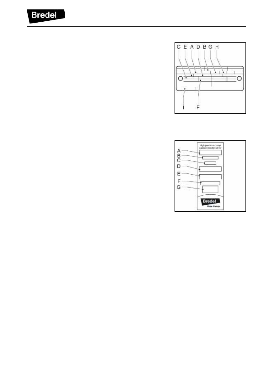
4.1.5 Identification of the pump hose
The identification stic ker on the pump hose cont ai ns the
following data:
A: Pump type
B: Reorder number
C: Internal diameter
D: Type of material of inner liner
E: Remarks, if applicable
F: Maximum permissible working pressure
G: Production code
DESCRIPTION
15
Page 16
DESCRIPTION
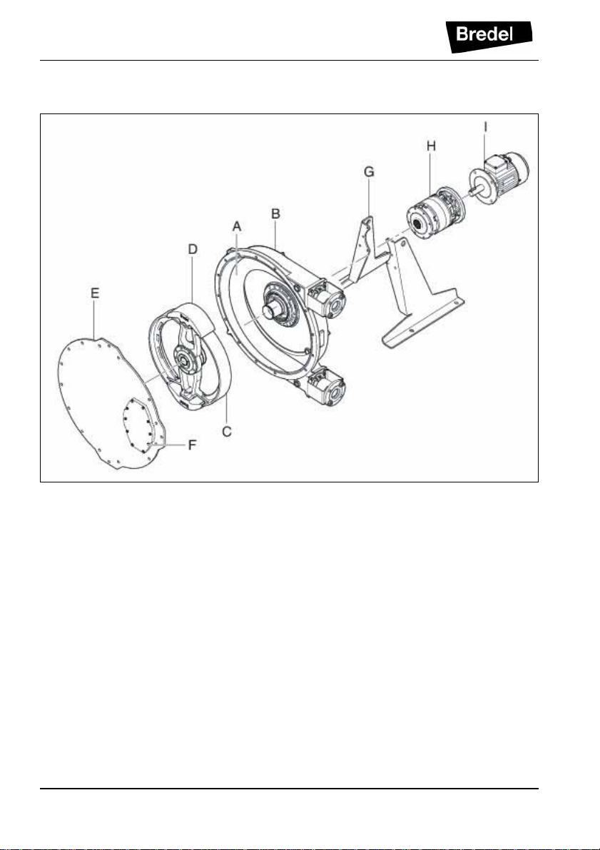
4.2 Construction of the pump
A: Pump hose
B: Pump housing
C: Rotor
D: Pressing shoes
E: Cover
F: Inspection window
G: Supports
H: Gearbox
I: Electric motor
4.3 Operation of the pump
The heart of the pump head consists of a specially
constructed pump hose (A) which lies contorted against
the inside of the pump housing (B). Both ends of the
hose are c onnected to the suction and discha rge lines
16
Page 17
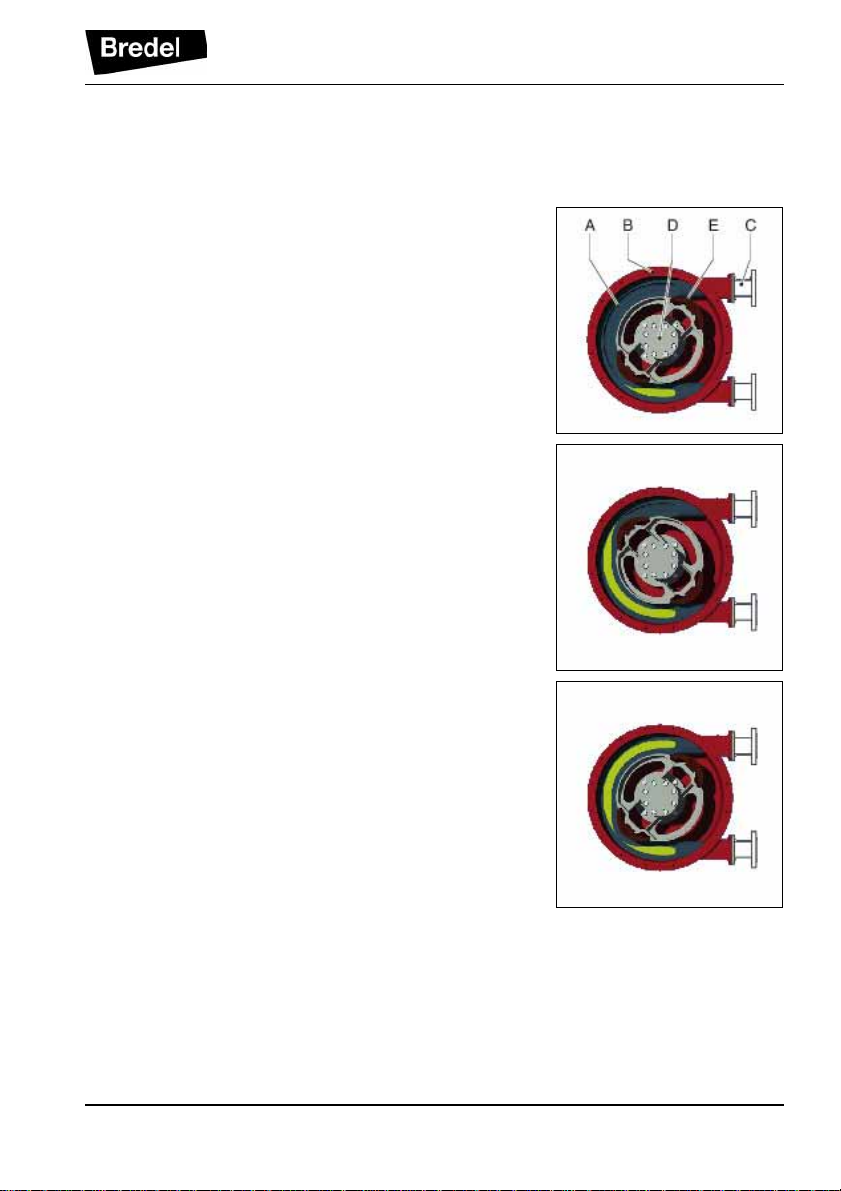
by means of a flange construction (C). A bearingmounted rotor (D) with two facing pressing shoes (E) is
in the centre of the pump head.
In phase 1 the lower pressing shoe compresses the
pump hose by the rotational movement of the rotor,
forcing the fluid through the hose. As soon as the
pressing shoe has passed, the hose recovers to its
original shape due to the mechanical properties of the
material.
In phase 2 the product is drawn into the hose by the
(continuous) turning motion of the rotor.
DESCRIPTION
In phase 3, the second pressing shoe will subsequently
compress the pump hose. Due to the continuous
rotating movement of the rotor not only new product is
sucked in, but also the already present product is
pressed out by the pressing shoe. When the first
pressing shoe runs from the pump hose, the second
pressing shoe has already closed the pump hose and
the product is prevented from flowing back. This
method of liquid displacement is also known as the
"positive displaceme nt principle".
17
Page 18
DESCRIPTION
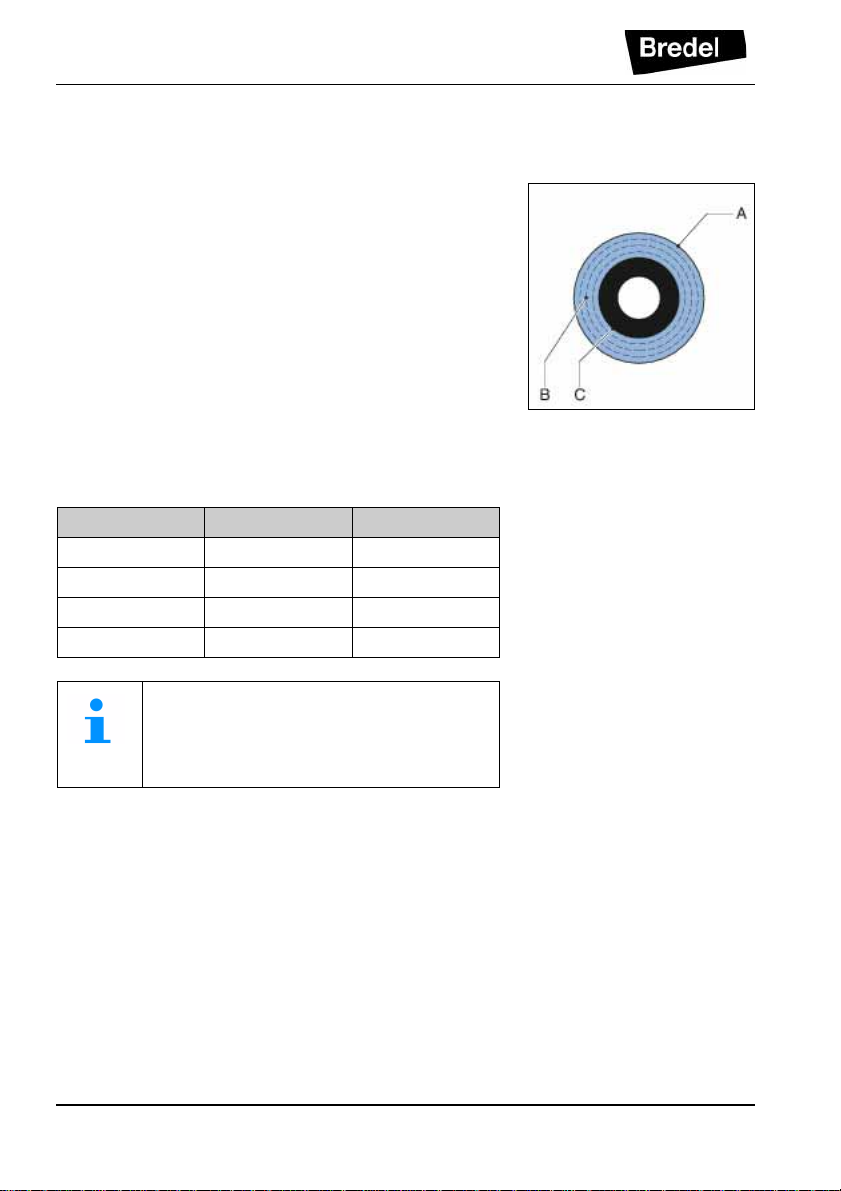
4.4 Pump hose
4.4.1 General A: Outer extruded layer made of natural rubber B: Four nylon reinforcement layers C: Inner extruded liner
The pump hose liner material should be chemically
resistant with the product to be pumped. Dependent on
the specific requirements of your application a
corresponding pump hose must be selected. For each
pump model various hose types are available.
The material of the inner liner of the pump hose
determines the hose type. Each hose type is marked by
a unique colour code.
Hose type Material Colour code
NR Natural rubber Purple
NBR Nitrile rubber Yell ow
EPDM EPDM Red
CSM CSM Blue
Consult your Bredel representative for
more detailed information about the chem ical and temperature resistance of pump
hoses.
The Bredel pump hoses have been carefully machined,
therefore there are minimum tolerances in wall
thickness. It is very important to guarantee the correct
compression of the pump hose, because:
• When the compre ssion is too high , it creates a
too high load of the pump and pump hose,
which may result in a reduction of the life of the
pump hose and bearings.
• When the compression is too low, this will result
in loss of yield and backflow. Backf low res ults in
a reduction of the life of the pump hose.
18
Page 19
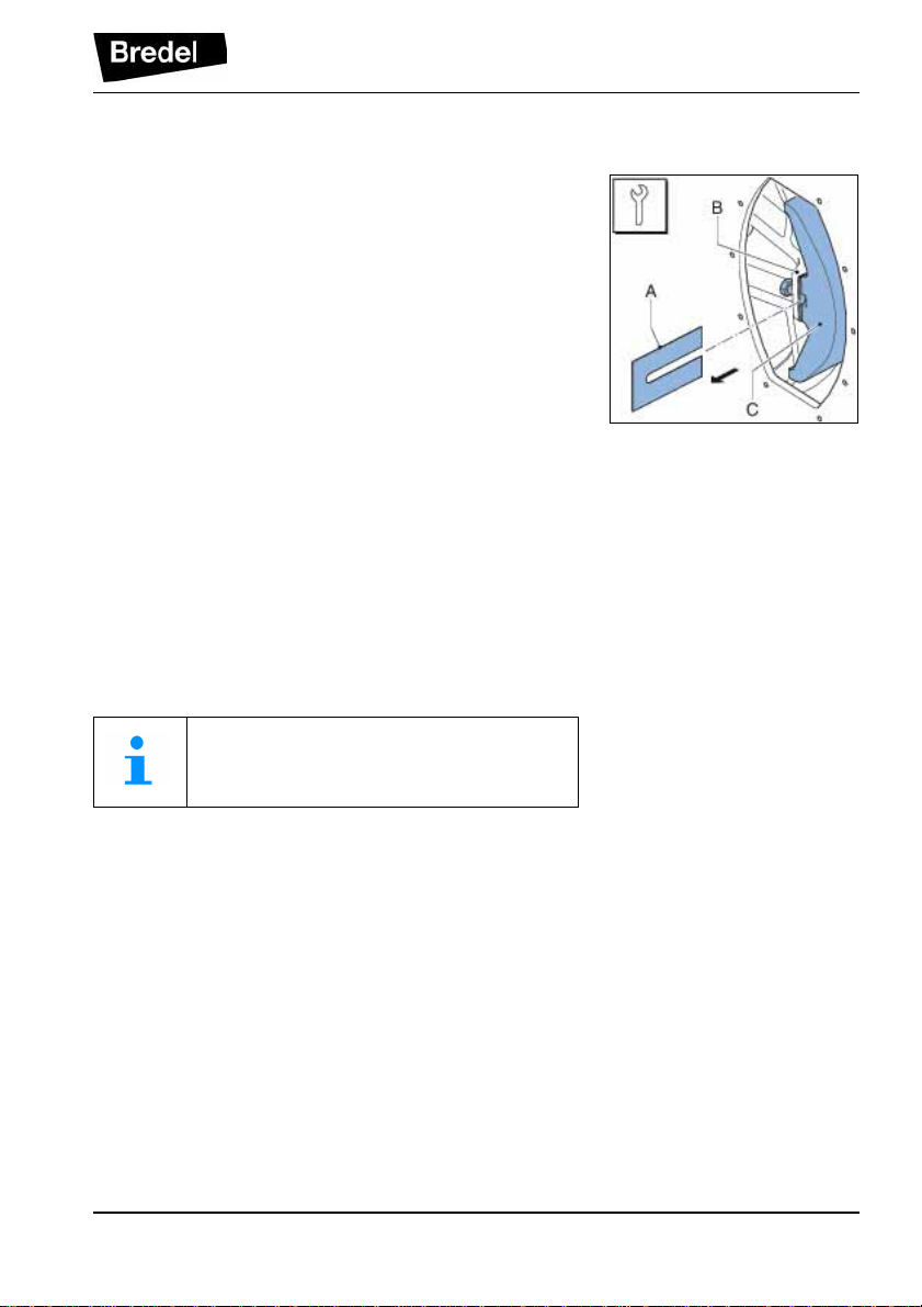
4.4.2 Hose compression force adjustment
(shimming)
In order to achieve optimal life of the pump hose, the
compression force of the pump hose can be adjusted by
placing a number of shims under the pressing shoes.
The shims (A) are fitted between the rotor (B) and the
pressing shoe (C). The number of shims will vary for
each counterpressure situation.
The paragrap h 7.8 describes how to sele ct and install
the shims.
4.4.3 Lubrication and cooling
The pumphead, in which the rotor and pump hose can
be found, is filled with Bredel Genuine Hose Lubricant.
This lubricant lubricates the movement between the
hose and the pressing shoes and dissipates the
generated heat via the pump housing and the cover.
The lubricant is food grade. See § 10.1.4 for the
required quantity and NSF registration.
DESCRIPTION
Consult your Bredel representative for
lubrication recommendations when operating the hose pump below 2 rpm.
4.5 Gearbox
The hose pump types described in this manual use
planetary gearbox units. The gearbox units are
characterized by their compact and modular
construction.
This modular construction enables a wide range of
reductions, torques and connection possibilities for the
electric motor.
19
Page 20

DESCRIPTION
4.6 Electric motor
If the electric motor has been standard supplied by the
manufacturer, it is a standardized squirrel-cage motor.
Refer to § 10.3 for specifications. If the pump is to be
used in potentially explosive atmospheres, contact your
Bredel representative.
4.7 Available options
The following options are available for the hose pump:
• High (lubricant) level float switch
• Low (lubricant) level fl oat switch
• Revolution counter
• Adapter for heavy duty drive (Bredel 65 and
Bredel 80 only)
The high level flo at switc h is mand ator y for
use in potentially explosive atmospheres.
If the pump is to be used in potentially
explosive atmospheres, contact your
Bredel representative.
20
Page 21

5 INSTALLATION
5.1 Unpacking
When unpacking carefully follow the instructions as
given on the packaging or on the hose pump.
5.2 Inspection
Check that your delivery is correct and check it for any
transport damage. Refer to § 4.1.1. Report any damage
immediately to your Bredel representative.
5.3 Installation conditions
5.3.1 Ambient conditions
Make sure that the hose pump is in an area where the
ambient temperature during operation is not lower than
-20 °C and not higher than +45 °C.
5.3.2 Set-up
• The pump materials and protective layers are
suitable for indoor set-up and a protected
outdoor set-up. Under certain conditions the
pump is suitable for limited outdoor set-up or a
salty or aggressive atmosphere. Consult your
Bredel representative for more information.
• Make sure that the floor surface is horizontal
and has a maximum slope of 10 mm per metre.
• Make sure that there is sufficient room around
the pump to carry out the necessary
maintenance activities.
• Make sure that the room is sufficiently
ventilated, so that the heat developed by the
pump and drive can be discharged. Keep some
distance between the ventilation cover of the
electric motor and wall to enable the supply of
necessary cooling air.
INSTALLATION
21
Page 22

INSTALLATION
5.3.3 Pipework
When determining and connecting suction and
discharge lines consider the following points:
• The bore size of the suction an d dis ch arge lin es
must be larger than the bore size of the pump
hose. For more information consult your Bredel
representative.
• Limit the presence of sharp bends in the
discharge line. Make sure that the radius of the
bent discharge line is as large as possible
(preferably 5S). It is recommended to use Yconnections instead of T-connections.
• Keep the piping at a minimum equal to or
greater than the bore si ze of the pum p. Inc rease
the bore size of the pipe work when the duty
fluid has a high velocity or inertia. This will help
keep friction and impulse losses to a minimum.
Where critical velocities are a concern consult
your Bredel representative.
• For the flexible hoses select compatible
materials and ensure the installation is suited
for the design pressure of the system.
• Keep the delivery and suction lines as sh ort a nd
direct as possible.
• Prevent any possibilities of exceeding the
maximum working pressure of the hose pump.
Refer to § 10.1.1. If necessary fit a pressure
relief valve.
CAUTION
Consider the maximum permissible working pressure on the discharge side.
Exceeding the maximum working pressure
may lead to serious damage to the pump.
• Make sure that the maximum forces on the
flanges are not exceeded. The permissible
loads are given in the following table.
22
Page 23
Maximum permissible loads [N] on the pump
flange
Force Bredel 40Bredel 50Bredel 65Bredel 80Bredel
100
F1 1000 1400 1400 2000 2000
F2 200 300 300 400 400
F3 500 700 700 1000 1000
5.4 Lifting and moving the pump
For lifting and moving the pump, it has been fitted w ith a
lifting point. This lifting point (A) is fitted on the upper
side of the cover. The m ax im um ra tin g of the lifting point
depends on the pump mode l. Make s ure that the tot al of
weight to be moved will not exceed this maximum
rating.
For the weights, refer to § 10.1.5.
INSTALLATION
Maximum rating of the lifting point of the pump
head
Bredel 40Bredel 50Bredel 65Bredel 80Bredel
100
200 kg 390 kg 670 kg 1020 kg 1580 kg
The complete hose pump, i.e. pump head, gearbox and
electric motor, must be lifted using the lifting point of the
pump head plus additional support using suitably rated
straps or slings (A). Never exceed the maximum rating
of the lifting point of the pump head.
WARNING
If the pump is to be lifted ensure that all
standard lifting practices are adhered to
and carried out by qualified personnel only.
23
Page 24

INSTALLATION
WARNING
Do not use the holes in th e pum p supports
to lift the hose pump.
5.5 Placing the pump
Position the pump on a horizontal surface. Use suitable
anchor bolts to attach the pump to the floor surface.
24
Page 25

6 COMMISSIONING
6.1 Preparations
1. Connect the electric motor in conformance with
the locally applicable rules and regulations.
Ensure that the electrical installation work is
carried out by qualified personnel.
2. Check that the lubricant level is above the
minimum level line in the inspection window. If
necessary add Bredel Genuine Hose Lubricant
via the breather/vent plug. See also § 7.4.
3. Check the rotation direction of the rotor.
4. Check that the correct number of shims
corresponds with your application. Refer to
§ 10.1.7.
For adjusting the compression force of the
hose, refer to § 7.8.
COMMISSIONING
6.2 Commissioning
1. Connect the pipework. Make sure that there are
no obstructions such as closed valves.
2. Switch on the hose pump.
3. Check the rotation of the pump rotor.
4. Check the capacity of the hose pump. If the
capacity differs from your specification, follow
the instructions in chapter 9 or consult your
Bredel representative.
5. Check the hose pump in acc orda nc e w it h po in ts
1 to 4 of the maintenance table from §7.2.
25
Page 26

MAINTENANCE
7 MAINTENANCE
7.1 General
WARNING
Only use original Bredel parts when maintaining the hose pump. Bredel cannot
guarantee a correct functioning and any
consequential damage that occurs from
the use of non-original Bred el components.
See also chapters 2 and 3.
WARNING
If the cover is removed when the pump
hose is still in the pump head, the compression forces on the pump hose may
cause deformation of the pump housing.
The hose needs to be safely removed
before the cover can be replaced.
Normally the compression forces are partially compensated by the cover.
7.2 Maintenance and periodic inspections
The following maintenance scheme shows the
maintenance and periodic inspections that need to be
carried out on the hose pump to guarantee an optimal
safety, operation and life of the pump.
26
Page 27

MAINTENANCE
Point Action To be carried out Remark
1 Check the lubricant
level.
Before startup of the
pump and on a scheduled interval duri ng o peration.
Make sure that the lubricant level is above the
minimum level lin e in the
inspection window.
If necessary refill the
lubricant. See also § 7.4.
2 Check the pump head
for any leakage of lubricant around the cover,
the flanges and the rear
Before startup of the
pump and on a scheduled interval duri ng o peration.
See § 9.
of the pump head.
3 Check the gearbox on
any leakage.
Before startup of the
pump and on a scheduled interval duri ng o per-
In case of leakage consult your Bredel representative.
ation.
4 Check pump for deviat-
ing temperature or
On a scheduled interval
during operation.
See § 9.
strange noises.
5 Check pressing shoes
for excessive damage.
6 Internal cleaning of the
pump hose.
7 Replacing pump hose. Preventive, this means
When replacing the
pump hose.
Cleaning of the system
or product change.
See § 7.6.
See § 7.3.
See § 7.6.
after 75% of the hose li fe
of the first hose.
8 Changing lubricant. After every 2
nd
hose
See § 7.4
change or after 5,000
service hours, whic hever
comes first or after hose
rupture.
9 Changing oil in gearbox. After the first 100 ser vice
See § 7.5.
hours and subsequently
annually or every 2500
service hours.
10 Replacing pump seal. If necessary. See § 7.7.2.
27
Page 28

MAINTENANCE
Point Action To be carried out Remark
11 Replacing wear ring. If necessary. See § 7.7.2.
12 Replacing pressing
shoes.
13 Replacing bearings. If necessary. See § 7.7.3.
7.3 Cleaning the pump hose
The inside of the pump hose can be easily cleaned by
rinsing the pump with clean water. If a cleaning fluid is
added to the water, check if the hose liner material is
resistant to it. Also check if the pump hose can resist
the cleaning temperature. Special cleaning balls are
also available. Contact your Bredel representative for
more details.
Wear on the runni ng s urface.
In potentially explosive
atmospheres preventive
after 20,000 hrs. service
or when damage is suspected.
See § 7.7.1.
See § 7.7.1.
Exclusively applic able in
potential l y explosive
atmospheres (Group II
Appliances, category
2GckT4).
7.4 Changing lubricant
1. Place a tray (A) under the drain plug in the
bottom of the pump. Remove the drain plug (B).
Drain the lubricant from the pump housing into
the tray. Check that the sealing ring (C) is not
damaged and replace it if necessary. Position
the drain plug and tighten it firmly.
28
Page 29

2. The pump housing can be filled with lubricant
via the breather/vent (A) on the rear of the
pump housing. For this purpose remove the
breather cap (B) and position a funnel (C) in the
breather. In order to facilitate the filling with
lubricant the plug (D) on the front of the pump
housing can be removed. Pour the lubricant in
the pump housing via the funnel. Continue until
the lubricant level has reached above the
minimum level line.
For the required quantity of lubricant, refer
to § 10.1.4.
7.5 Changing oil in gearbox
1. Isolate the pump from the electrical supply.
2. Position a tray under the gearbox. Remov e pl ug
(A) and drain the gearbox.
3. The plug (A) is magnetically loaded. In this way
metal particles in the oil are pulled to the plug.
Clean the plug and remove any metal particles
if necessary. Check that the sealing ring is not
damaged and replace it if necessary. Place the
plug back in the gearbox and tighten it firmly.
MAINTENANCE
4. Remove level plug (B) and breather (C).
Position a funnel in the hole of breather (C) and
fill the gearbox with oil until the oil just comes
out of the level plug hol e (B). Pl ace plu g (B) a nd
plug (C) back and tighten them firmly.
For the required lubricant, refer to § 10.2.
5. Switch on the electrical supply to the pump.
29
Page 30

MAINTENANCE
7.6 Replacing pump hose
7.6.1 Removing pump hose
1. Isolate the pump from the electrical supply.
2. Close any shut-off valves in both the suction
and discharge line to minimize product loss.
3. Place a tray (A) under the drain plug in the
bottom of the pump head. The tray must be
large enough to contain the lubricant, possibly
contaminated with product fluid, from the pump
head. Remove the drain plug (B). Catch the
lubricant from the pump housing in the tray.
Check that the breather vent mounted on the
rear is not obscured. C h ec k th at t he s ea lin g ri ng
(C) is not damaged and replace it if necessary.
Position the drain plug and tighten it firmly.
4. Loosen the retaining bolts (A) of both the
suction and discharge line (B). Disconnect the
suction and discharge lines.
5. Loosen hose clamp (A) of both the inlet and
outlet ports by loosening retaining bolt (B).
30
Page 31

6. Pull the insert (B) from the ho se an d remove the
flanges (A). Carry out this procedure both for
the inlet and outlet ports.
7. Loosen the retaining bolts (A) of the flange
bracket (B) and remove the bolts. Slide the
flange bracket and the hose clip (C) off the
hose. Carry out this procedure both for the inlet
and outlet ports.
8. Slide off the sealing ring (A). Check that the
sealing ring is not deformed or damaged and
replace it if necessary. Carry out this procedure
both for the inlet and outlet ports.
MAINTENANCE
9. Connect the pump to the electrical supply.
31
Page 32

MAINTENANCE
10. Power out the hose (A) from the pump chamber
by jogging the drive motor.
WARNING
During jogging the drive:
- Do not stand in front of the pump
ports.
- Do not try to guide the hose by
hand.
7.6.2 Cleaning the pump head
1. Isolate the pump from the electrical supply.
WARNING
Never dismount the cover, when the pump
hose is in the pump head. The compression forces on the pump hose are partially
compensated by the cover. By removing
the cover, the pump housing may become
deformed.
2. Use lifting hole (D) to move the cover. Remove
the cover (B) by loosening the retaining bolts
(A).
3. Check the sealing ring (C) and replace it if
necessary.
4. Rinse the pump head with clean water and
remove all residues. Make sure that no rinsing
water remains in the pump head.
32
Page 33

5. Check the pressing shoes for wear or damage
and replace them if necessary. Refer to § 7.7.1.
Also see the maintenance scheme in § 7.2.
CAUTION
When the pressing shoes are worn the
compression force of the hose decreases.
If the compression force is too low, this
results in a loss of cap acity by the backflow
of the liquid to be pumped.
Backflow result s in a reduct ion of the life of
the pump hose.
6. Replace the cover and fasten the retaining bolts
with the correct torque. Refer to § 10.1.6.
7. Switch on the electrical supply to the pump.
7.6.3 Fitting the pump hose
1. Clean the (new) pump hose on the outside and
fully lubricate it with Bredel Genuine Hose
Lubricant.
MAINTENANCE
2. Fit the pump hose (A) via one of the ports.
3. Let the motor run to draw the hose in the pump
housing. The rotor will move the hose. Stop the
motor when the hose protrudes out equally fro m
both sides of the pump housing.
WARNING
During jogging the drive:
- Do not stand in front of the pump
ports.
- Do not try to guide the hose by
hand.
33
Page 34

MAINTENANCE
4. First fit the inlet port. Fit the sealing ring. Before
mounting, check that the sealing ring (A) is not
deformed or damaged and replace it if
necessary.
5. Before fitting check that the hose clamp is not
damaged and replace it if necessary. Slide the
flange bracket (B) and the hose clamp (C) over
the hose together. Align the holes in the flange
bracket with the ones at the front of the port.
Position the four retaining bolts (A) and tighten
them until they are approx. 5 mm from the port,
so that the gap between the flange bracket and
the port remains.
6. Slide insert (B) in the flange (A) and press the
insert in the hose. If necessary lubricate the
insert with Bredel Genuine Hose Lubricant in
order to simplify mounting. Make sure that the
holes in flange (A) are aligned with the holes in
flange bracket (C). Check that the insert is in
the correct place. If the insert is not positioned
correctly the product to be pumped may leak or
the lubricant may leak.
7. Turn the rotor in such a way that the hose (A) is
pressed firmly against the flange surface (B).
34
Page 35

8. Now fully tighten the retaining bolts (A) of the
flange bracket (B). Make sure the bolts are
tightened with the correct torque. Refer to
§ 10.1.6.
9. Position hose clamp (A) against O-ring cham ber
of the flange bracket (B) and fasten the
retaining bolt. Make sure the bolts are tightened
with the correct torque. Refer to § 10.1.6.
10. Now fit the other port. For this port proceed in
the same way as described above for the inlet
port.
11. Fill the pump housing with Bredel Genuine
Hose Lubricant. Refer to §7.4.
12. Connect the suction and discha rge line s (B) and
fit the retaining bolts (A). Tighten the retaining
bolts with the correct torque. Refer to § 10.1.6.
MAINTENANCE
35
Page 36

MAINTENANCE
7.7 Exchanging replacement parts
7.7.1 Replacing pressing shoes
1. Jog the motor until the pressing shoe (B) is
positioned in view of the inspection window (A).
2. Isolate the pump from the electrical supply.
3. Place a tray (A) under the drain plug (B) in the
bottom of the pumphead. Remove the drain
plug. Drain as much Bredel Genuine Hose
Lubricant until the level has lowered just below
the inspection window (D). Check that the
sealing ring (C) is not damaged and replace it if
necessary. Position the drain plug and tighten it
firmly
4. Loosen the retaining bolts (A) of the inspection
window (B) and remove the bolts. Remove the
inspection window. Care must b e taken not to
damage the gasket (C).
36
Page 37

5. Loosen the retaining bolt(s) (A) of pressing
shoe (B) a few turns. Remove the shims (C) if
present. Loosen the retaining bolt(s) (A) of
pressing shoe (B) completely and remove the
pressing shoe.
MAINTENANCE
6. Position the (new) pressing shoe (A), ch eck th at
the NordLock
®
-rings (B) have been positioned
correctly and tighten the retaining bolt(s) a few
turns.
7. Fit the removed shims (A) again. Tighten the
retaining bolt(s) (B) with the correct torque.
Refer to § 10.1.6.
8. Refit the inspection window (B). Check the
inspection window gasket (C) for damag e and
replace if necessary. Make sure that all bolts (A)
are refitted and that they are tightened in the
correct order, diagonally opposite each other.
9. Switch on the electrical supply.
10. Jog the motor until the second pressing shoe is
positioned in front of the inspection window.
37
Page 38

MAINTENANCE
11. Isolate the pump from the electrical supply.
12. Repeat the procedure for removing and fitting
this second pressing shoe by repeating steps 4
through 9.
13. Refill the lubricant. Refer to § 7.4.
7.7.2 Replacing seal and wear ring
1. Remove the pump hose. Refer to § 7.6.1.
2. Isolate the pump from the electrical supply.
3. Use lifting hole (D) to move the cover. Remove
the cover (B) by loosening the retaining bolts
(A). Check the sealing ring (C) of the pump
cover for damage.
4. Remove the retaining bolts (A) of the drive shaft
(B) and remove the drive shaft. Check the
sealing ring (C) for damage.
If the drive shaf t cannot be removed manu ally, use a screwdriver in the slots in the
rotor provided for this purpose.
5. Remove the rotor retaining circlip (A), which
locks the rotor on the hub. Use the correct tools
to do this.
38
Page 39

6. Fit the necessary lifting means before
dismounting the rotor. Extract the rotor (A) from
the hub. A suitable puller or similar extraction
tool will be required during this stage of the
disassembly.
WARNING
When removing the rotor a belt or similar
lifting aid mu st carry the w eight of th e rotor .
For the specific weight of the rotor, refer to
§ 10.1.5.
7. Remove the seal (A) from the hub (B). Clean
and degrease the bore.
8. Fit a new seal using a wooden block and
hammer. Carefully hit the seal crosswise and
with equal strength in the bore until it touches
the hub. The seal must be fitted in the correct
orientation (C). Make sure that the open side
points to the pump cover.
MAINTENANCE
9. Support the rotor with wooden blocks at 90° to
the spokes, with the ring (A) facing down.
Position a suitable punch against the rear of the
glued wear ring. Prevent damage to the wear
ring seat or other parts.
39
Page 40

MAINTENANCE
10. Turn the rotor over. Make sure that the seats of
the new we ar ring (A) and rotor are cl ean, dry
and free of grease. Apply Loctite
®
type 641 or
603 both on the rotor and the wear ring.
Position the new wear ring with the tapered
edge facing up. Use a plastic hammer to fit the
ring on the rotor until it touches the rotor
completely.
11. Check that the hub is clean and free of grease.
Fit rotor (A). The bearings have been placed on
the hub with a slight interference fit. Use a
pressing tool to press the rotor on the hub.
12. Check rotor retaining circlip (A) for any signs of
damage and replace if necessary. Refit the
circlip. Use the correct tools for this purpose.
13. Heavily grease the spline (D) of the drive shaft
(B) with a graphite-loaded grease. Ensure the
mating faces of the drive shaft and rotor are
clean, dry and free from lubricant. Check that
the sealing ring (C) is not damaged and replace
it if necess ary. Fit the seal ing ring in th e gro ove
of the shaft flange. Fit the drive shaft. Turn the
40
Page 41

rotor until the bolt holes in the drive shaft
correspond with the threaded holes in the rotor.
Mount the re taining bolts (A) of the d rive shaft.
Tighten the bolts finger-tight. Tighten them
diagonally opposite to each other to the
specified torque limits. Refer to § 10.1.6.
14. Replace the cover and fasten the retaining bolts
with the correct torque. Refer to § 10.1.6.
15. Switch on the electrical supply to the pump.
16. Fit the (new) pump hose. Refer to § 7.6.3.
7.7.3 Replacing bearings
1. Dismount the pump hose, the cover and rotor
by following steps 1 through 6 from § 7.7.2.
2. Lay the rotor on a flat surface with the wear ring
face up. Remove retaining circlip (A) with the
correct tools.
MAINTENANCE
3. Turn the rotor over. Remove using the correct
pressing tools, first the first bearing (C), the
spacer ring (B) and the second be arin g (A) from
the rotor. Check the spacer ring for damage.
Retain the spacer ring (B).
41
Page 42

MAINTENANCE
4. Turn the rotor over. Check that the hub is clean
and dry. Press using the pressing tool the firs t
bearing (C) in its place. Position the spacer ring
(B). Subsequently press the second bearing (A)
in its place.
5. Refit the retaining circlip (A) i n t he roto r. Use the
correct tools for this purpose.
6. Fit the rotor, the cover and pump hose by
following steps 11 through 16 from § 7.7.2.
7.8 Adjusting hose compression force (shimming)
Fitting and removing shims is a simple action which can
be carried out via the inspection window on the front of
the pump housi ng. The pump hose or the pump cover
does not need to be removed. In order to determine the
correct number of shims for your specific application
refer to § 10.1.7.
CAUTION
Too many shims, this means a too high
compression force on the pump hos e, create a too high load on the pump head and
pump hose, which results in a reduction of
the life of the pump hose and bearings.
42
Page 43

CAUTION
Too few shims, this means a too low compression force on the pump hos e, crea te a
loss of yield and slip or backflow. Backflow
results in a re duction of the life of the pum p
hose.
1. Jog the motor until the pressing shoe (B) is
positioned in view of the inspection window (A).
2. Isolate the pump from the electrical supply.
3. Place a tray (A) under the drain plug (B) in the
bottom of the pump head. Remove the drain
plug. Drain as much Bredel Genuine Hose
Lubricant until the level has lowered just below
the inspection window (D). Check that the
sealing ring (C) is not damaged and replace it if
necessary. Position the drain plug and tighten it
firmly.
MAINTENANCE
4. Loosen the retaining bolts (A) of the inspection
window (B) and remove the bolts. Remove the
inspection window. When doing this prevent the
gasket (C) from damaging.
43
Page 44

MAINTENANCE
5. Loosen the retaining bolt(s) (A) of pressing
shoe (B) a few turns. Fit the shims (C) or
remove them, until the correct number of shims
is present. Refer to § 10.1.7. Tighten the
retaining bolt(s) of the pressing shoe with the
correct torque. Refer to § 10.1.6.
6. Check the inspection window gasket for
damage and replace if necessary. Refit the
inspection window (B). Make sure that all bolts
(A) are refitted and that they are tightened in the
correct order, diagonally opposite each other, to
the specified torque limits. Refer to §10.1.6.
7. Switch on the electrical supply.
8. Jog the motor until the second pressing shoe is
positioned in front of the inspection window.
9. Isolate the pump from the electrical supply.
10. Repeat the procedure for this pressing shoe by
repeating steps 4, 5, 6 and 7.
11. Refill the lubricant via the breather. Refer to
§ 7.4.
44
Page 45

7.9 Fitting options
7.9.1 Fitting a high-level float switch
MAINTENANCE
For explosive environments, contact your
Bredel representative.
1. Dismount the standard breather (A) on the rear
of the pump, by dismounting it from crimp
connector (B).
2. Slide the standard breather cap (A) from
breather (B).
3. Replace the standard breather cap with the
breather cap with high level float switch (A) and
slide it over breather (B).
45
Page 46

MAINTENANCE
4. Fit the breather (A) on the rear of the pump, by
mounting it to crimp connector (B).
5. Connect the high-level float switch to the
auxiliary po wer circui t via th e 2-m etre long PVC
cable (2 x 0.34mm
2
). Bear in mind that the
electrical contact of the float switch is normally
closed (NC). The knob is upwards for normally
closed operation. When the lubricant level is
(too) high the contact will open.
Specifications
*
Voltage: Max. 230 V AC/DC
Current: Max. 2 A
Power: Max. 40 VA
* For use in non-explosive atmospheres
Where the float switch is constructed to
stop the equipment, operating has to be
arranged so that the stop function locksout, preventing the equipment from being
re-started without re-setting. Check if the
float switch is mounted with the NC si gn a t
the top.
46
Page 47

7.9.2 Fitting a low level float switch
MAINTENANCE
For explosive environments, contact your
Bredel representative.
For specifications, refer to § 7.9.1.
1. If the pump is filled with lubricant this must be
removed first. Place a clean tray (A) under the
drain plug in the bottom of the pump. Remove
the drain plug (B). Drain the lubricant from the
pump housing into the tray. Check the sealing
ring (C) for damage.
2. Fit the crimp connector (A) together with the
sealing ring (B) to the pump housing. Fit the
low-level float switch (C) to the crimp connector
(A).
3. Connect the low-level float switch to the
electrical supply. Bear in mind that the electrical
contact of the float switch is normally closed
(NC). When the lubricant level is (too) low the
contact will open.
4. Refill the pump housing to the proper level with
Bredel Genuine Hose Lubricant.
5. Breath the float switch by carefully opening plug
(D) until lubricant escapes. Subsequently close
the plug again.
7.9.3 Fitting revolution counter
1. Remove one of the pressing shoes of the rotor
by following steps 1 through 5 from § 7.7.1.
47
Page 48

MAINTENANCE
2. Replace pressing shoe by the special pressing
shoe with a magnet (A) by following the steps 6
through 8 from § 7.7.1.
3. Fit the inductive sensor (A) in plug (B) and
adjust it to dimension "X" as indicated in the
table below.
Pump type Dimension “X”
Bredel 40 32 +0 /-1
Bredel 50 32 +0 /-1
Bredel 65 32 +0 /-1
Bredel 80 45 +0 /-1
Bredel 100 45 +0 /-1
4. Tighten the adjusting nuts.
5. Remove a plug (A) and the sealing ring (B) on
the back side of the pump housing.
48
Page 49

6. Fit the plug with the inductive sensor (A)
together with sealing ring (B) on the pump
housing.
7. Refill the pump housing to the proper level with
Bredel lubricant.
MAINTENANCE
8. Connect the sensor via the 2-meter long PVC
cable (3 x 0.34 mm
2
).
Specifications
Voltage: 10...30 VDC
Current: Max. 150 mA
WARNING
Contact your Bredel representative for
proper connection of the sensor.
For explosive environments, contact your
Bredel representative.
49
Page 50

STORAGE
8 STORAGE
8.1 Hose pump
• Store the hose pump or pump parts in a dry
area. Make sure that the hose pump or pump
parts are not exposed to temperatures lower
than -40 °C or higher than +70 °C.
• Cover the openings of the inlet and outlet ports.
• Prevent corrosion of untreated parts. For this
purpose use the correct protection or packaging
means.
• After a long period of standstill or storage, the
static load on the pump hose may have caused
permanent deformation, which will reduce the
life of the pump hose. To prevent this, remove a
pressing shoe. Jog the rotor until the second
pressing shoe is positioned between the inlet
and outlet port. In this way there is no load put
on the pump hose.
8.2 Pump hose
• Store the pump hose in a cool and dark room.
After two years the h ose m aterial will age , which
will reduce the life of the hose.
50
Page 51

TROUBLESHOOTING
9 TROUBLESHOOTING
WARNING
Disconnect and lock the power su pp ly to the pu mp driv e befor e any work is
carried out.
In case the motor is fitted with a frequency controller and has a singlephase power supply, wait two minutes to make sure that the capacitors
have discharged.
If the hose pump does not function (correctly), consult the following checklist to see if
you can remedy the error yourself. If this is not the case, contact your Bredel
representative.
Problem Possible cause Correction
Failure to operate. No voltage. Check that the supply power
switch is on.
Check the electrical supply is
available at the pump.
Stalled rotor. Check if the pump is stalled by
incorrect fitting of the hose.
Lubricant level monitoring
system has been ac tiva ted.
Check that the lubricant level monitoring system has stalled the
pump.
Check the functioning of the lubri cant level monitoring system, or
check the lubricant level .
51
Page 52

TROUBLESHOOTING
Problem Possible cause Correction
High pump tem-
perature.
Non standard hose lubricant used.
Low lubricant level. Add Bredel Genuine Hose Lubri-
Consult t h e Bredel representative
for the correct lubricant.
cant. For the required amount of
lubricant refer to § 10.1.4.
Product temperature too
high.
Internal friction o n the hose
caused by blocked or poor
suction characteristic s.
Over-shimming of the
pump rotor shoes.
High pump speed. Reduce pump speed to a mini-
Consult t h e Bredel representative
about the maximum temperature
range of the product.
Check pipework/valves for blockages. Ensure that the sucti on p ipework is as sh ort as possible and
that the diameter is large enough.
Consult the diagram. Refer to
§ 10.1.7. Remove excess shims.
mum. Consult with your Bredel
pump representative for advice on
optimum pump speeds.
52
Page 53

Problem Possible cause Correction
Low capacity /
pressure.
Shut-off valve in the suction line (partly) closed.
Fully open the shut-off valve .
TROUBLESHOOTING
Under shimming of the
pressing shoes.
Hose rupture or badly wo rn
hose.
(Partial) blockage of the
suction line or too little
product on the suction
side.
Connections and hose
clamps not correctly
mounted, which makes th e
pump suck air.
The filling degree of the
pump hose is too low,
because the speed is too
high in relation to the viscosity of the product to be
pumped and the inlet pressure.
The suction l ine c an be to o
long or too narrow or a
combination of these factors.
Consult the diagram in § 10.1.7.
Fit the correct number of shims.
Replace hose. Refer to § 7.6.
Ensure that the suction line is cl ear
of blockages and that sufficient
product is available.
Tighten connections and hose
clamps.
Consult your Bredel repres entative
for a recommendation.
53
Page 54

TROUBLESHOOTING
Problem Possible cause Correction
Vibration of the
pump and pipework.
Suction and discharge
lines are not secured correctly.
Check and secure pipework.
High pump speed with lon g
suction and discharg e lines
or high relative den sity or a
combination of these factors.
Too narrow diameter of
suction an d/or discharge
line.
Broken front
cover bolts.
Short hose life. Chemical attack of the
Pump cover (dis)mounted
with the hose in the pump.
hose.
High pump speed. Reduce pump speed.
High discharge pressures. Maximum working pressure
High product temperature. Consult your Bredel representative
Reduce pump speed.
Reduce the line lengths on both
suction and discharge where possible. Consult your Bredel representative for a recommendation.
Increase the diameter of the suction/disc harge lines.
Never (dis)mount the pump cover
when the hose is still in the pump.
Check the compatibility of the hose
material with the product to be
pumped. Consult your Bredel representative for correct hose selection.
1600 kPa. Check that the discharge line is not blocked, the
shut-off valves are ful ly opened
and the pressure relief valve functions properly (if present in the discharge line).
for correct hose selection.
54
High pulsations. Restructure the discharge and inlet
conditions.
Page 55

Problem Possible cause Correction
Hose pulled into
the pump.
Insufficient or no hose
lubricant in the pump he ad.
Add extra lubricant. Refer to § 7.4.
TROUBLESHOOTING
Lubricant leakage at flange
bracket.
Leakage from the
rear of the pump
housing "Buffer
zone".
Motor functions,
but rotor does
not.
Incorrect lubricant: no
Bredel Genuine Hose
Lubricant in the pump
head.
Extremely high inlet pressure - larger than 300 kPa.
Hose blocked by an inc om pressible object in the
hose. The hose cannot be
compressed and will be
pulled into the pump housing.
Bolts of flange bracket
loose.
Bolts of hose clamps loose. Tighten to the specified torque set-
Damaged wear or sealing
ring.
Broken undercut on the
pump shaft.
Consult the Bredel representative
for the correct lubricant.
Reduce the inlet pressure.
Remove hose, check for blockages and replace if necessary.
Tighten to the specified torque settings. Refer to § 10.1.6.
tings. Refer to § 10.1.6.
Replace wear or sealing ring.
Follow installation procedure supplied with replacement shaft.
55
Page 56

SPECIFICATIONS
10 SPECIFICATIONS
10.1 Pump head
10.1.1 Performance
Description Bredel 40Bredel 50Bredel 65Bredel 80Bredel
100
3
Max. capacity, continuous [m
Max. capacity, intermittently [m
/h] 6.0 10.5 20.0 28.0 36.0
3
*
/h]
9.6 17.5 32.0 42.0 60.0
Capacity per revolution [l/rev] 1.33 2.9 6.7 1 1. 7 20.0
Max. permissible working pressure [kPa] 1600
Permissible ambient temperature [°C] -20 to +45
Permissible product te m per at ur e [ °C] -10 to +80
Sound level on 1 m [dB(A)] 70
* Intermitted duty: Let the pump stand still to cool down for at least 1 hour after 2 hours of
operation.
56
Page 57

10.1.2 Materials
SPECIFICATIONS
Pos Description Material
1 Pum p housing Cast-iron
2 Cover Commercial grade mi ld st eel 37
3 Pum p ro to r Cast-iron
4 Pres sing shoes Aluminium (Epoxy opt io nal)
5 Supports Mild steel , galvanised
6 Hose flange brackets Mild steel, galvanised
7 Cover fixings Mild steel , galvanised
8 Motor fixings Mild steel , galvanised
9 Mounting material of supports Mild steel, galvanised
10 Seals and glands Neoprene or Nitrile
57
Page 58

SPECIFICATIONS
10.1.3 Surface treatment
• After surface preparation, one layer of two-component acrylate is used for
surface protection. Standard colour is RAL 3011, however other colours are
optional. Contact your Bredel representative for details on surface treatment.
• All galvanised parts have been provided with an electrolytic zinc layer of 15 - 20
microns.
10.1.4 Lubricant table pump
Bredel 40Bredel 50Bredel 65Bredel 80Bredel
100
Lubricant Bredel
*
Bredel*Bredel*Bredel*Bredel
Required quantity [litres] 5 10 20 40 60
* Bredel Genuine Hose Lubricant is registered at NSF: NSF Registration No 123204; Cate-
gory Code H1. See also: www.NSF.org/ USDA .
Should you require additional information with respect to the safety data
sheet, cons ult your Brede l representative.
10.1.5 Weights
*
Description Weight [kg]
Bredel 40Bredel 50Bredel 65Bredel 80Bredel
100
Hose pump, maximum w eight
Pump head
Rotor 14244077 118
Pressing shoe 0.8 1.8 4 6.6 12.6
Pump cover 16 30 62.5 106.5 195
Drive shaft 2.5 5.9 7.7 16.6 19.5
Hub 10161838 53
Hose 3.8 6.4 11.5 21 31
* Maximum net weight of the hose pump with the heaviest gearbox and electric motor.
** Weight of a completely mounted pump head (inclusive of hose, lubricant and supports).
**
*
180 325 558 930 1300
121 227 398 672 1032
58
Page 59

10.1.6 Torque figures
DBCAF E H
G I
SPECIFICATIONS
Pos Description Torques [Nm]
Bredel 40Bredel 50Bredel 65Bredel 80Bredel
100
A Pressing shoe bolt(s) 50 85 85 208 208
B Inspection window 5 8 8 8 8
C Cover 50 85 210 210 400
D Hose clamp
*
25 40 40 40 40
E Flange bracket 25 50 50 85 85
F Drive shaft 25 50 85 210 210
G Hub 50 50 85 210 210
H Supports 50 50 85 210 210
I Gearbox 25 85 85 85 135
* Due to creeping of the hose material, the hose clamp force reduces in time. If leakage
starts, re-tighten the hose clamp to the specified torque level. The listed torque values
apply to a new hose clamp.
59
Page 60

SPECIFICATIONS
10.1.7 Shims specifications
• When the product temperatures are above 60 °C always use one s him less th an
indicated in the diagrams.
• Always round up the number of shims.
60
Page 61

SPECIFICATIONS
10.2 Lubricant table gearbox
Below is an overview of some of the recommended lubricants for the planetary gearbox.
In the majority of the cases a mine ral oil ISO VG 150 or ISO VG 220 is reco mmended . In
case of very low or ambient temperatures a mineral ISO VG 100 is advised. In case of
high ambient temperatures or relatively wide range of ambient temperatures a synthetic
oil is recommended. Also in case of very high loads, resulting in high operating
temperatures a synthetic oil is to be preferred. Contact your Bredel representative for
advice.
Recommended lubr icants for the B r edel planetary gearboxes
-20 °C / +5 °C
IV 95 min
ISO 3448 VG 100 VG 150 VG 320 VG 150 - 220
AGIP Blasia 100 Blasia 150 Blasia 320 Blasia SX 220
ARAL Drgol BG 100 Drgol BG 150 Drgol BG 220 Drgol PAS 220
BP MACH Energol GR-XP
100
CASTROL Al ph am ax 100 Alphamax 150 Alphamax 320 Alphasyn SN 150
ESSO Spartan EP 100 Spartan EP 150 Spartan EP 320 Spartan SEP 200
Q8 Goya NT 100 Goya NT 150 Goya NT 320 El Greco 220
I.P. Mellana 100 Mellana 150 Mellana 320 Telesia Oil 150
MOBIL Mobilgear XMP
100
SHELL Omala oil 100 Omala oil 150 Omala oil 320 Omala HD 220
TOTAL Carter EP 100 Carter EP 150 Carter EP 320 Carter SH 220
KLÜBER Kluberoil GEM
1-150
Texaco Meropa 100 Me ropa 15 0 Meropa 320 Pinnac le E P 220
* For a complete overview of the recommended lubricants contact your Bredel representa-
tive.
+5 °C / +30 °C
IV 95 min
Energol G R-XP
150
Mobilgear XMP
150
Kluberoil GEM
1-150
+30 °C / +50 C
IV 95 min
Energol GR-XP
320
Mobilgear XMP
320
Kluberoil GEM
1-320
*
-30 °C / +65 °C
IV 165 min
Enersyn EXP 220
Mobilgear SHC
XMP 220
Klubersynth EG
4-220
61
Page 62

SPECIFICATIONS
10.3 Electric motor
Construction IM B5 (flange type)
Materials size IEC-80/90:
Housing and connecti on box: aluminium
End shields: cast-iron
size IEC-100 and larger :
Housing, connection box and end shields: cast-iron
Number of poles 4 or 6 poles
Voltage - frequency
*
up to 2.2 kW:
230 / 400 V - 3 phases - 50 Hz
3.0 kW and larger:
400 / 690 V - 3 phases - 50 Hz
Protection class in accor d-
IP55
ance with IEC 34-5
Insulation class F
Temperature class B
* unless specified otherwise
62
Page 63

10.4 Parts list
10.4.1 Overview
SPECIFICATIONS
Pos. Description
1 Cover assembly. Refer to § 10.4.2.
2 Rotor assembly. Refer to § 10.4.3.
3 Pump housing assembly. Refer to § 10.4.4.
4 Pump support assembly. Refer to § 10.4.5.
5 Flange assembly. Refer to § 10.4.6.
6 Lubricant. Refer to § 10.4.8.
63
Page 64

SPECIFICATIONS
10.4.2 Cover assembly
Pos. Qty. Description Product codes for parts of pump type
Bredel 40Bredel 50Bredel 65Bredel 80Bredel
1 1 Sticker 240238 250238 265238 280238 200238
2 8 Bolt, hex . he ad F111042 F111074 F101038 F101038 F101040
3 8 Washer, plain F322009 F322012 F322012 F322012 F3220 12
4 1 Inspec tion window 240155 250155 265155 280155 200155
5 1 Gasket 240156 250156 265156 280156 200156
6 14 Bol t, hex. head F111096 F1111 30 F111182 F1111 82 F11121 8
7 14 Washer, plain F322013 F322 015 F322017 F322017 F322019
8 1 Pump cover 240102 250102 265102 280102 200102
9 1 Quad ring 240123 250123 265123 280123 200123
100
64
Page 65

SPECIFICATIONS
10.4.3 Rotor assembly
Pos. Qty. De sc ription Product codes for parts of pump type
Bredel 40Bredel 50Bredel 65Bredel 80Bredel
18
28
3 1 Dri ve shaft
*
Bolt, h ex. head F111073 F111 098 F11113 2 F111184 F111184
*
Washer, spring Lock F336011 F336012 F3 36013 F336015 F336015
**
240104 250104 265104 280104 200104
4 1 O-ring S122431 S122541 122541 122611 S122611
***
52
62
Bolt, hex. head F101058 F101082 F101085 F101131 F101132
***
NordLock® ring F34900 5 F349007 F349007 F349009 F349009
7 1 Rotor 240103 250103 265103 280103 200103
****
812
9 2 Pressing shoe: alu-
Shim 240107 250107 265107 280107 20010 7
240110 250110 265110 280110 200110
minium
2 Epoxy , with st ainless
240109A 250109A 265109A 280109A 200109A
steel insert
10 1 Retaining ring F343056 F343071 F343071 F34307 5 F343075
11 2 Bearing B141460 B142060 B142060 B142460 B 142460
12 1 Spacer outside 29110201 29150201 29151201 29180201 29181201
100
65
Page 66

SPECIFICATIONS
Pos. Qty. Description Product codes for parts of pump type
Bredel 40Bredel 50Bredel 65Bredel 80Bredel
100
13 1 Retaining ring F344077 F344087 F344087 F344 093 F344093
14 1 Wear ring 29140202 29180202 29180202 29240202 29240202
* Pos. 1 and 2: Bredel 65, Bredel 80, Bredel 100: 12 pieces
** Pos. 3: Standard drive shaft. For the drive shaft of the Bredel 65 heavy duty drive (gear-
*** Pos. 5 and 6: Bredel 65, Bredel 80, Bredel 100: 4 pieces
**** Pos. 8: Bredel 40: 12 pieces, Bredel 50 and Bredel 100: 14 pieces, Bredel 65 and Bredel
boxes G0217… and G0218…) and the Bredel 80 heavy duty drive (gearboxes G0224…
and G0225…), consult your Bredel representative.
80: 20 pieces
10.4.4 Pump housing assembly
Pos. Qty. Description Product codes for parts of pump type
Bredel 40Bredel 50Bredel 65Bredel 80Bredel
1 1 Pump housing 240101 250101 265101 280101 200101
2 4 Packing ring 29040257 29040257 29040257 29056244 29056244
3 2 Plug, int. hex. hd F901006 F901006 F901006 F901008 F901008
4 1 Breather cap 29065223 29065223 29065223 29089223 29089223
5 1 Breather 29110146 29110146 29110146 29125146 29125146
66
100
Page 67

SPECIFICATIONS
Pos. Qty. De sc ription Product codes for parts of pump type
Bredel 40Bredel 50Bredel 65Bredel 80Bredel
100
6 1 Co upling, straight F602006 F602006 F602006 F602008 F602008
7 2 Plug, ext. hex. hd. F911006 F911006 F911006 F91 1008 F911008
8 1 O-ring S122641 S122711 S122711 S122771 S122801
9 1 Do wel pi n F416082 F 416082 F416082 F416121 F416 121
10 1 Hub 240203 250203 265203 280203 200203
11 8 Washer, spring Lock F336012 F336 012 F336013 F336015 F336015
12 8 Bolt, hex. head F115098 F115098 F115132 F115186 F115186
13 1 Seal S212811 S213611 S213611 S214811 S214811
14 1 NR 040020 050020 065020 080020 100020
1 NBR 040040 050040 065040 080040 100040
1 EPDM 040075 050075 065075 080075 100075
1 CSM 040070 050070 065070 080070 100070
15 8 Washer
*
F332005 - - - 10 - F332007 F332007 F332007 12 - - - - F332010
16 8 Bolt, hex. socket ca p
10 - F201106 F201106 F201106 -
head
*
F201064 - - - -
12 - - - - F201250
* For fixation of the standard drive. For fixation of the Bredel 65 heavy duty drive (gearboxes
G0217... and G0218...) and the Bredel 80 heavy duty drive (gearboxes G0224... and
G0225...), consult your Bredel representative.
67
Page 68

SPECIFICATIONS
10.4.5 Support assembly
Pos. Qty. Description Product code s fo r parts of pump type
Bredel 40Bredel 50Bredel 65Bredel 80Bredel
100
1 1 Support, right 240106B 2501 06B 265106B 28 0106B 200106B
2 1 Support, left 240106A 250106A 265106A 280106A 200106A
3 8 Washer, spring Lock F336012 F336012 F336013 F336015 F336015
4 8 Bolt, hex. head F111096 F111098 F111132 F111186 F111186
68
Page 69

SPECIFICATIONS
10.4.6 Flange assembly
Pos. Qty. Description Product codes for parts of pump type
Bredel 40Bredel 50Bredel 65Bredel 80Bredel
1 2 O-ring S112301 S112371 S 112431 S112501 S115571
2 2 Flange bracket, DIN
Steel
2 Flan ge bracket, DIN SS 240197E 250197 E 265197E 280197E 200197E
2 Flange bracket, ANSI
Steel
2 Flange bracket, ANSI SS240197F 250197E 265197E 280197F 200197E
240197 250197 265197 280197 200197
240197A 250197 265197 280197A 200197
100
3 8 Washer, spring lock F336011 F336012 F336012 F33601 3 F336013
4 8 Bolt, hex. head F111071 F111096 F111096 F111128 F111130
5 2 Hose clamp C101021 C101045 C101048 C101 051 C101054
6 2 Flange, DIN Steel 040198 050198 065198 080198 100198
2 Flan ge, DIN SS 240199 250199 265 199 280199 200199
2 Flan ge, ANSI Steel 040198A 050198A 06 5198A 080198A 100198A
2 Flan ge, ANSI SS 240199A 250199A 265199A 280199A 200199A
69
Page 70

SPECIFICATIONS
Pos. Qty. Description Product codes for parts of pump type
Bredel 40Bredel 50Bredel 65Bredel 80Bredel
7 1 Insert, AISI 316 040186 050186 265186 280186 200186
1 Insert, PP 240189 250189 265189 280189 200189
1 Insert, PVC 240187 250187 265187 280187 200187
1 Insert, PVDF 240190 250190 265190 280190 200190
10.4.7 Revolution counter assembly
100
Pos. Qty. Description Product codes for parts of pump type
Bredel 40Bredel 50Bredel 65Bredel 80Bredel
1 1 Gasket 29040257 29040257 29040257 29056244 29056244
2 1 Revolution counter 29040462 29040462 29040462 29040462 29040462
3 1 Adapter 29039460 29039460 29039460 29055460 29055460
70
100
Page 71

SPECIFICATIONS
10.4.8 Lubricants
Pos. Qty. De sc ription Product codes for parts of pump type
Bredel 40Bredel 50Bredel 65Bredel 80Bredel
1 1 5 l can Bredel Genu-
ine Hose Lubr i cant
1 10 l can Bredel Gen-
uine Hose Lubricant
1 20 l can Bredel Gen-
uine Hose Lubricant
2 - - - 905143 3 - - - - 905143
903143 - - - -
- 904143 - - -
- - 905143 - -
100
71
Page 72

ORIGINAL
EC Declaration of Con formity for machinery
EC DECLARATION OF CONFORMITY OF THE MACHINERY
(according to Annex II.1.A. of Directive 2006/42/EC on machinery)
We,
Watson -Ma rlow Bredel B.V .
Sluisstraat 7
P.O. Box 47
7490 AA Delden
The Netherlands,
herewith declare, on our own responsibility, that the following machinery fulfils all the
relevant provisions of Directive 2006/42/EC:
Peristaltic hose pump: Bredel 40-100 series,
for the transportation of various kinds of fluids.
In addition, the machi nery co mplie s with the h armoni sed s tan dard(s ), other st and ards or
technical specifications, applicable requirements of these standards and/or
specifications as listed below:
NEN-EN 809
NEN-EN-ISO 12100-2
NEN-EN-IEC 60204-1
The undersigned is responsible for compilation of the technical file and makes this
declaration on behalf of the manufacturer.
J. van den Heuvel
Managing Director
The Netherlands, Delden
1 June 2013
72
Page 73

SAFETY FORM
Safety form
SAFETY FORM
Product Use and Decontamination Declaratio n
In compliance with the Health and Safety Regulations, the user is re quired to declare those substances that
have been in contact with the item(s) you are returning to Watson-Marlow Bredel B.V. or any of its subsidiaries or
distributors. Failure to do so will cause delays in servicing the item or in issuing a response. Therefore, please
complete this form to make sure we have the information before receipt of the item(s) being returned. A completed copy must be attached to the outside of the packaging containing the item(s). You, the user, are responsible for cleaning and decontaminating the item(s) before returning them.
Please complete a separate Decontamination Certificate for each item returned. RGA/KBR no...................
1 Company ............................................................. .........................................................................................
Address ................. ........... .......... ........... .......... ..... ............... .......... ...... .......... ........... .....................................
Postal code...........................................................
Telephone .............................................................
2 Product ................................................................ 3.4 Cleaning fluid to be used if residue of chemical is
2.1 Serial Number ......................................................
2.2 Has the Product been used?
YES NO
If yes, please complete all the following para-
graphs.
If no, please complete paragraph 5 only
3 Details of substances pumped 4 I hereby confirm that the only substances(s) that
3.1 Chemical Names
a) ...................... ................ ............... ................ .....
b) ...................... ................ ............... ................ .....
c) ...................... ............................... .....................
d) ...................... ................ ............... ................ .....
3.2 Precautions to be taken in handling these substances:
a) ...................... ................ ............... ................ .....
b) ...................... ................ ............... ................ .....
c) ...................... ............................... .....................
d) ...................... ................ ............... ................ .....
3.3 Action to be taken in the event of human contact:
a) .........................................................................
b) .........................................................................
c) .........................................................................
d) .........................................................................
Fax number ..........................................................
found during servicing;
a) ........................................................................
b) ........................................................................
c) ......................... ..... ...... ..... ..... ..... ...... ...............
d) ........................................................................
the equipment specified has pumped or come into
contact w it h a r e t h ose na me d , th at t h e in f or ma t ion
given is correct, and the carrier has been informed
if the consignment is of a hazardous nature.
5 Signed ............. ....................................................
Name ......................... ........................... ...............
Position ...................... ...... ..... ..... ..... .....................
Date ...................... .......................... .....................
Note:
To assist us in our servicing please describe
any fault condition you ha ve witn essed.
.............................................................................
.............................................................................
.............................................................................
.............................................................................
.............................................................................
73
Page 74

NOTES
Notes
NOTES
74
Page 75

NOTES
75
Page 76

Watson-Marlow Bredel B.V.
P.O. Box 47
NL-7490 AA Delden
The Netherlands
Telephone: +31 (0)74 3770000
Fax: +31 (0)74 3761175
E-mail: bredel@wmpg.com
Internet: http://www.bredel.com
76
29210301 TS 02-002-E
© 2013 Watson-Marlow Bredel B.V.
 Loading...