

Page 1

Disc
The disc, which is inserted in the cover, contains the user manual(s) of the Bredel 265,
Bredel 280 and Bredel 2100 hose pumps in the following languages:
English (UK)
English (US)
Español
Français
The disc also contains quick-reference instructions for the replacement of the pump
hose. This replacement instruction is only for users that are familiar with the
replacement procedures in the user manual.
How to use the disc
1 Put the disc in the disc drive.
2 Close the disc drive.
The disc will start automatically.
3 Wait until the various language versions appear on screen.
4 Select the required language (click 1x with the left mouse button).
The PDF reader program will automatically start and the required user manual
appears on screen.
Shortcuts
In the left margin you will find the various chapters and paragraphs. These can be
accessed directly by clicking on the required chapter or paragraph.
In the text you will find hyperlinks to chapters or paragraphs. These hyperlinks are linked
with the required chapters or paragraphs. By clicking a shortcut the required chapter or
paragraph appears on screen.
System requirements
The program on the disc requires a PC with the following minimum system
requirements:
Nederlands
Polski
Portiguês
Svenska
Suomi
• Disc drive
The following software must be installed on the PC:
• PDF reader program
• an Internet browser
1
Page 2

2
Page 3
Hose pump series
Bredel 265, Bredel 280 and Bredel 2100
Manual
Hose Pumps
TYPE EL - CLASS I
AUGUST 2012
ISO
9001
Quality
Management
ISO
14001
Environmental
Management
3
Page 4

© 2013 Watson-Marlow Bredel B.V.
All rights reserved.
The information provided herein may not be reproduced and/or published in any form,
by print, photoprint, microfilm or any other means whatsoever (electronically or
mechanically) without the prior written authorisation of Watson-Marlow Bredel B.V.
The information provided can be changed without prior notification. Watson-Marlow
Bredel B.V. or one of its representatives cannot be held liable for possible damage
resulting from use of this manual. This is an extensive limitation of the liability which
applies to all damage, inclusive of (without limitation) compensating, direct , indirect or
consequential damage, loss of data, income or profit, loss or damage to possessions
and claims of third parties.
Watson-Marlow Bredel B.V. provides the information in this manual "as is" and does not
take any responsibility and does not give any guarantee on this manual o r its content.
Watson-Marlow Bredel B.V. rejects all responsibilities and guarantees. Furthermore,
Watson-Marlow Bredel B.V. does not take responsibility for and does not guarantee that
the information in this manual is accurate, complete or up to date.
Names, trade names, brands, etc. used by Watson-Marlow Bredel B.V. may not, as per
the legislation concerning the protection of trade names, be considered as available.
4
Page 5

CONTENTS
1GENERAL
1.1 How to use this manual .................................. ........................................ 8
1.2 Original instructions ................................................................................ 8
1.3 Other supplied documentation ................................................................ 8
1.4 Service and support .................................................................... ... ... ...... 8
1.5 Environment and disposal of waste ........................................................ 9
2SAFETY
2.1 Symbols ................................................................................................ 10
2.2 Intended use ......................................................................................... 10
2.3 Responsibility ........................................................................................ 11
2.4 Qualification of the user ........................................................................ 11
2.5 Regulations and instructions ................................................................. 12
3 WARRANTY CONDITIONS
4 DESCRIPTION
4.1 Identification of the product ................................................................... 14
4.1.1 Identification of the product ....................................................... 14
4.1.2 Identification of the pump .......................................................... 14
4.1.3 Identification of the gearbox ...................................................... 14
4.1.4 Identification of the electric motor .............................................. 15
4.1.5 Identification of the pump hose ................................................. 15
4.2 Construction of the pump ...................................................................... 16
4.3 Operation of the pump .......................................................................... 16
4.4 Pump hose ...................................... .. ..................................... ... ............ 18
4.4.1 General ...................................................................................... 18
4.4.2 Hose compression force adjustment (shimming) ...................... 19
4.4.3 Lubrication and cooling ............................................................. 19
4.5 Gearbox ................................................................................................ 19
4.5.1 General ...................................................................................... 19
4.5.2 Maintenance .............................................................................. 20
4.6 Electric motor ........................................................................................ 20
4.7 Available options ................................................................................... 21
5 INSTALLATION
5.1 Unpacking ............................................................................................. 22
5.2 Inspection ............................................................................................. 22
5
Page 6

5.3 Installation conditions ........................................................................... 22
5.3.1 Ambient conditions .................................................................... 22
5.3.2 Set-up ........................................................................................ 23
5.3.3 Pipework ................................................................................... 23
5.3.4 Flange sizes of the pipework ..................................................... 26
5.4 Lifting and moving the pump ................................................................ 27
5.4.1 Lifting the complete unit ............................................................ 27
5.4.2 Lifting the pumphead ................................................................. 28
5.4.3 Lifting the pump cover ............................................................... 28
5.5 Placing the pump .................................................................................. 28
6 COMMISSIONING
6.1 Preparations ......................................................................................... 31
6.2 Commissioning ..................................................................................... 31
7 OPERATION
7.1 Temperature ......................................................................................... 32
7.2 Power rating ................................................. ... ... .................................. 32
7.3 Dry running ........................................................................................... 34
7.4 Hose failure ...................................................................................... ... . 35
7.5 Fluid leakage ........................................................................................ 35
8 MAINTENANCE
8.1 General ................................................................................................. 37
8.2 Maintenance and periodic inspections ................................................. 38
8.3 Cleaning the pump hose ...................................................................... 40
8.4 Changing lubricant ............................................................................... 40
8.5 Changing oil in gearbox ........................................................................ 41
8.6 Replacing pump hose ........................................................................... 41
8.6.1 Removing pump hose ............................................................... 41
8.6.2 Cleaning the pump head ........................................................... 44
8.6.3 Fitting the pump hose ................................................................ 45
8.7 Exchanging replacement parts ............................................................. 48
8.7.1 General ..................................................................................... 48
8.7.2 Replacing pressing shoes ......................................................... 48
8.7.3 Replacing seal and wear ring .................................................... 50
8.7.4 Replacing bearings ............................................................. .. .... 54
8.8 Adjusting hose compression force (shimming) ..................................... 55
8.9 Fitting options ....................................................................................... 58
8.9.1 Fitting a high-level float switch .................................................. 58
6
Page 7

8.9.2 Fitting a low level float switch .................................................... 59
8.9.3 Fitting revolution counter .......................................................... . 60
8.9.4 Installing the cover lifting device (CLD) on a horizontal
configuration .............................................................................. 62
8.9.5 Installing the cover lifting device (CLD) on a vertical
configuration .............................................................................. 63
9 STORAGE
9.1 Hose pump ........................................................................................... 65
9.2 Pump hose ...................................... .. ..................................... ... ............ 65
9.3 Electric motor and gearbox ................................................................... 65
10 TROUBLESHOOTING
11 SPECIFICATIONS
11.1 Pump head ........................................................................................... 71
11.1.1 Performance .............................................................................. 71
11.1.2 Materials .................................................................................... 72
11.1.3 Surface treatment ...................................................................... 73
11.1.4 Lubricant table pump ................................................................. 73
11.1.5 Weights ..................................................................................... 73
11.1.6 Torque figures ........................................................................... 74
11.1.7 Shims specifications .................................................................. 75
11.2 Lubricant for gearbox ............................................................................ 76
11.3 Parts list ................................................................................................ 76
11.3.1 Overview complete unit ............................................................. 76
11.3.2 Overview pump head ................................................................ 77
11.3.3 Cover assembly ......................................................................... 78
11.3.4 Rotor assembly ......................................................................... 79
11.3.5 Pump housing assembly ........................................................... 80
11.3.6 Flange assembly ....................................................................... 81
11.3.7 Lubricants per pumphead .......................................................... 82
11.3.8 Adaption assembly .................................................................... 83
11.3.9 Frame assembly ......................................................... ... ............ 85
11.3.10Shaft assembly ......................................................................... 87
11.3.11Revolution counter assembly .................................................... 88
EC DECLARATION OF CONFORMITY OF THE MACHINERY
SAFETY FORM
NOTES
7
Page 8

GENERAL
1GENERAL
1.1 How to use this manual
This manual is intended as a reference book by means
of which qualified users are able to install, commission
and maintain the hose pumps mentioned on the front
cover.
1.2 Original instructions
The original instructions for this manual have been
written in English. Other language versions of this
manual are a translation of the original instructions.
1.3 Other supplied documentation
Documentation of components such as motors,
gearboxes and inverters is normally not include d in this
manual. However, if additional documentation is
supplied, you must follow the instructions in this
additional documentation.
1.4 Service and support
For information with respect to specific adjustments,
installation, maintenance or repair jobs which fall
beyond the scope of this manual, contact your Bredel
representative. Make sure you have the following data
at hand:
• Serial number hose pump
• Article number pump hose
• Article number gearbox
• Article number electric motor
• Article number frequency controller
You will find these data on the identification plates or
stickers of the pumphead, the pump hose, the gearbox
and the electric motor. Refer to § 4.1.1.
8
Page 9

1.5 Environment and disposal of waste
CAUTION
Always observe the local rules and regulations with respect to processing (non reusable) parts of the hose pump.
Enquire within your local government about the
possibilities for reuse or environment-friendly
processing of packaging materials, (contaminated)
lubricant and oil.
GENERAL
9
Page 10

SAFETY
2SAFETY
2.1 Symbols
In this manual the following symbols are used:
WARNING
Procedures which, if not carried out with
the necessary care, may result in serious
damage to the hose pump or in serious
bodily harm.
CAUTION
Procedures which, if not carried out with
the necessary care, may result in serious
damage to the hose pump, the surrounding
area or the environment.
Remarks, suggestions and advice.
2.2 Intended use
The hose pump is exclusively designed for pumping
suitable products. Every other or further use is not in
conformance with the intended use.
The "Intended use" as laid down in EN 292-1 is "... the
use for which the technical product is intended in
accordance with the specifications of the manufacturer,
inclusive of his indications in the sales brochure". In
case of doubt it is the use which appears to be its
intended use judging from the construction, execution
and function of the product. Observing the instructions
in the user's documentation also belongs to intended
use.
Only use the pump in conformance with the intended
use described above. The manufacturer cannot be h eld
responsible for damage or harm resulting from use that
10
Page 11

is not in conformance with the intended use. If you want
to change the application of your hose pump, contact
your Bredel representative first.
2.3 Responsibility
The manufacturer does not accept any responsibility for
damage or harm caused by not (strictly) observing the
safety regulations and instructions in this manual and
the also supplied documentation, or by negligence
during installation, use, maintenance and repair of the
hose pumps mentioned on the front cover. Depending
on the specific working conditions or accessories used,
additional safety instructions can be required.
Immediately contact your Bredel representative, if you
noticed a potential danger while using your hose pump.
WARNING
The user of the hose pump is always fully
responsible for observing the local valid
safety regulations and directives. Observe
these safety regulations and directives
when using the hose pump.
SAFETY
2.4 Qualification of the user
The installation, use and maintenance of the hose
pump should only be performed by well-trained and
qualified users. Temporary staff and persons in training
may use the hose pump only under the supervision and
responsibility of trained and qualified users.
11
Page 12

SAFETY
2.5 Regulations and instructions
• Everyone who works with the hose pump must
be aware of the contents of this manual and
observe the instructions with great care.
• Never change the order of the actions to be
carried out.
• Always store the manual and the manuals of the
gearbox and the electric motor near the hose
pump.
12
Page 13

3 WARRANTY CONDITIONS
The manufacturer offers a two-year warranty on all
parts of the hose pump. This means that all parts will be
repaired or replaced free of charge, with the exception
of consumables such as pump hoses, hose clamps, ball
bearings, wear rings, seals and rubber bushes, or parts
which have been used wrongly, misused, whether or
not they have been intentionally damaged. If genuine
Watson-Marlow Bredel (hereafter called Bredel) parts
are not used, any warranty claim is void.
Damaged parts which are covered by the applicable
warranty conditions can be returned to the
manufacturer. The parts must be accompanied by a
fully filled in and signed safety form, as present in the
back of this manual. The safety form must be applied to
the outside of the shipping carton. Parts which have
been contaminated or which have been corroded by
chemicals or other substances which can pose a health
risk must be cleaned before they are returned to the
manufacturer. Furthermore, it should be indicated on
the safety form which specific cleaning procedure has
been followed, and that the equipment has been
decontaminated. The safety form is required even if the
parts have not been used.
WARRANTY CONDITIONS
Warranties purporting to be on behalf of Bredel B.V.
made by any person, including representatives of
Bredel B.V., its subsidiaries, or its distributors, which do
not accord with the terms of this warranty shall not be
binding upon Bredel B.V. unless expressly approved in
writing by a Director or Manager of Bredel B.V.
13
Page 14
DESCRIPTION
4 DESCRIPTION
4.1 Identification of the product
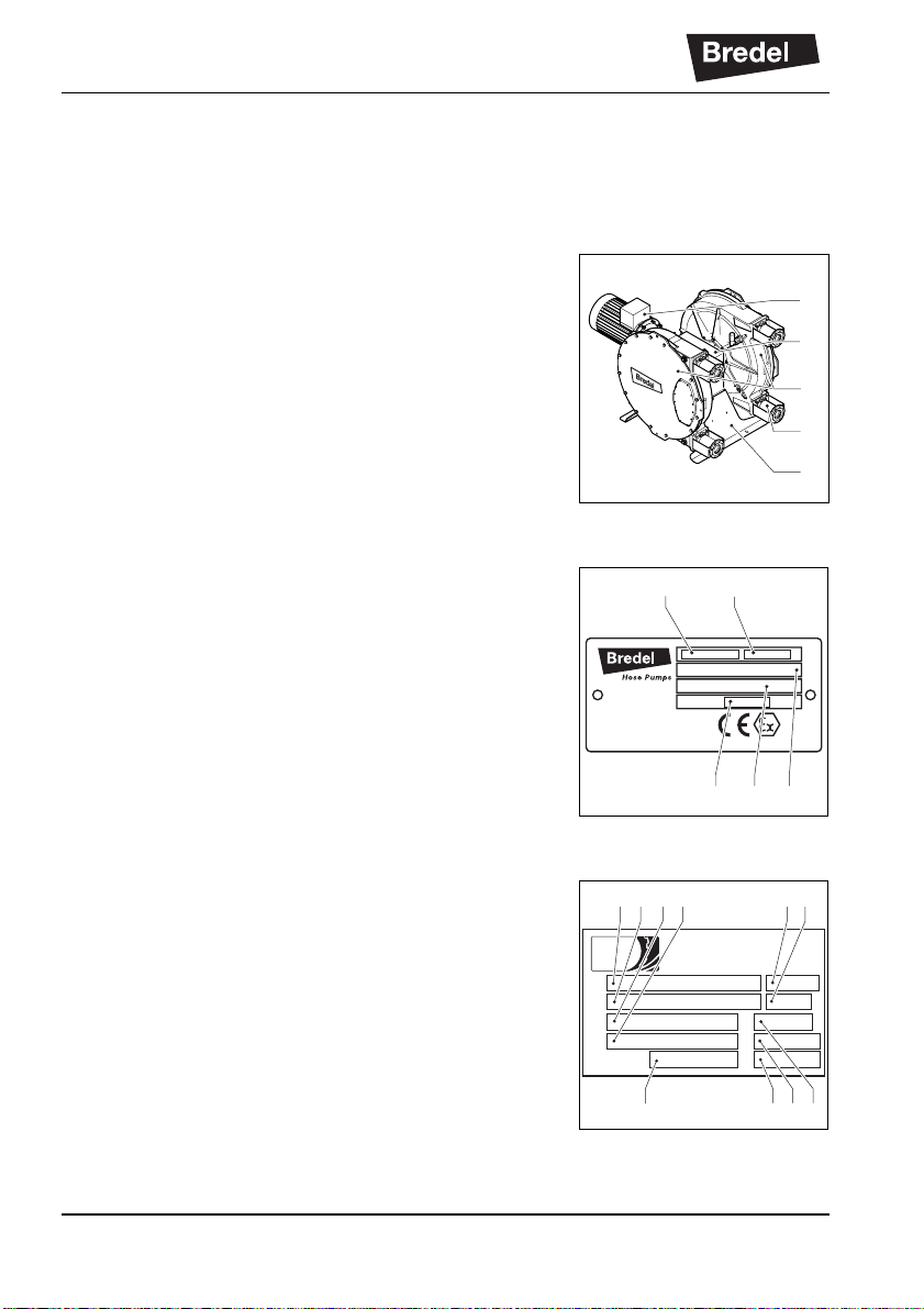
4.1.1 Identification of the product
The hose pump can be identified based on the
identification plates or stickers on:
A: Pumphead
B: Gearbox
C: Electric motor
D: Pump hose
E: Frame
4.1.2 Identifica tion of the pump
The identification plate on the pump head contains the
following data:
A: Type number
B: Serial number
C: ATEX code
D: ATEX document number
E: Year of manufacture
Hose Pumps
A
Watson-Marlow Bredel B.V.
Sluisstraat 7-Delden-NL
www.bredel.com
YEAR:
C
B
A
D
E
B
Patent applied
4.1.3 Identification of the gearbox
The identification plate on the gearbox contains the
following data:
A: Type number
B: Batch number
C: Motor power
D: Gear motor output speed
E: Gear reducer nomi nal power
F: Two months and year of manufacture
G: Mounting position
H: Gear motor service factor
J: Transmission ratio
K: Diameter Flange - motor shaft
14
E D C
A F GB C D
a company of the Habasit Group
Rossi
www.rossi-group.com Made in Italy
1423382
kW
-1
min
kW
EK
J H
Page 15

4.1.4 Identification of the electric motor
The identification plate on the electric motor contains
the following data:
A: Serial number
B: Type number
C: Power
D: Voltage
E: Frequency
F: Speed
G: Insulation class
H: Protection class
I: Bredel article or order number
4.1.5 Identif ication of the pump hose
The identification sticker on the pump hose contains the
following data:
A: Pump type
B: Reorder number
C: Internal diameter
D: Type of material of inner liner
E: Remarks, if applicable
F: Maximum permissible working pressure
G: Production code
DESCRIPTION
B A E
R
cosjIsol.
As. mot.
kW
V
DC
High precision pump
element machined for
No.
A
B
C
D
E
F
G
Hz.
-1
min
A
FIG H
15
Page 16

DESCRIPTION
4.2 Construction of the pump
B
A
D
I
H
E
C
F
A: Pump hose
B: Pump housing
C: Rotor
D: Pressing shoes
E: Cover
F: Inspection window
G: Frame
H: Gearbox
I: Electric motor
4.3 Operation of the pump
The heart of the pump head consists of a specially
constructed pump hose (A) which lies contorted against
the inside of the pump housing (B). Both ends of the
hose are connected to the suction and discharge lines
B
G
16
Page 17

by means of a flange construction (C). A bearingmounted rotor (D) with two facing pressing shoes (E) is
in the centre of the pump head.
DESCRIPTION
In phase 1 the lower pressing shoe compresses the
pump hose by the rotational movement of the rotor,
forcing the fluid through the hose. As soon as the
pressing shoe has passed, the hose recovers to its
original shape due to the mechanical properties of the
material.
In phase 2 the product is drawn into the hose by the
(continuous) turning motion of the rotor.
In phase 3, the second pressing shoe will subse quently
compress the pump hose. Due to the continuous
rotating movement of the rotor not onl y new product is
sucked in, but also the already present product is
pressed out by the pressing shoe. When the first
pressing shoe runs from the pump hose, the second
pressing shoe has already closed the pump hose and
the product is prevented from flowing back. This
method of liquid displacement is also known as the
"positive displacement principle".
D E CBA
17
Page 18
DESCRIPTION
4.4 Pump hose
4.4.1 General A: Outer extruded layer made of natural rubber B: Four nylon reinforcement layers C: Inner extruded liner
The pump hose liner material should be chemically
resistant with the product to be pumped. Dependent on
the specific requirements of your application a
corresponding pump hose must be selected. For each
pump model various hose types are available.
The material of the inner liner of the pump hose
determines the hose type. Each hos e ty pe i s marked by
a unique colour code.
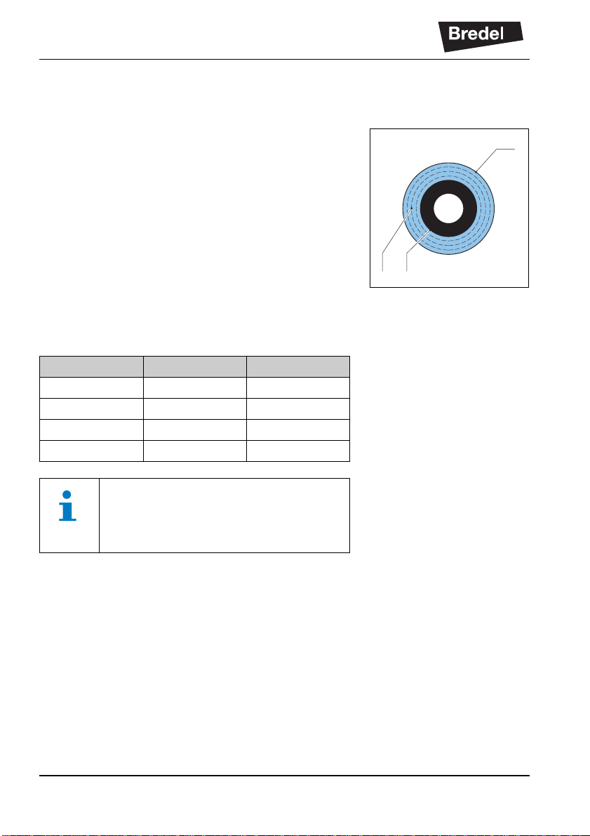
Hose type Material Colour code
NR Natural rubber Purple
NBR Nitrile rubber Yellow
EPDM EPDM Red
CSM CSM Blue
A
B C
Consult your Bredel representative for
more detailed information about the chemical and temperature resistance of pump
hoses.
The Bredel pump hoses have been carefully machined,
therefore there are minimum tolerances in wall
thickness. It is very important to guarantee the correct
compression of the pump hose, because:
• When the compression is too high, it creates a
too high load of the pump and pump hose,
which may result in a reduction of the life of the
pump hose and bearings.
• When the compression is too low, this will result
in loss of yield and backflow. Backflow results in
a reduction of the life of the pump hose.
18
Page 19

4.4.2 Hose compression force adjustment (shimming)
In order to achieve optimal life of the pump hose, the
compression force of the pump hose can be adjusted by
placing a number of shims under the pressing shoes.
The shims (A) are fitted between the rotor (B) and the
pressing shoe (C). The number of shims will vary for
each counterpressure situation.
DESCRIPTION
B
A
The paragraph 8.8 describes how to select and install
the shims.
4.4.3 Lubrication and cooling
The pumphead, in which the rotor and pump hose can
be found, is filled with Bredel Genuine Hose Lubricant.
This lubricant lubricates the movement between the
hose and the pressing shoes and dissipates the
generated heat via the pump housing and the cover.
The lubricant is food grade. See § 11.1.4 for the
required quantity and NSF registration.
Consult your Bredel representative for
lubrication recommendations when operating the hose pump below 2 rpm.
4.5 Gearbox
4.5.1 General
The hose pump types described in this manual use a
bevel-helical gearbox. The gearbox is mainly used for
high reduction ratios and low input speeds. This
modular construction enables a wide range of
reductions, torques and connection possibilities for the
electric motor.
C
19
Page 20

DESCRIPTION
4.5.2 Maintenance
For all information on maintenance and lubrications,
see the manual of the gearbox.
Check the oil level regularly. If necessary, refill the oil
level. Avoid mixing oils of different types. In case
of doubt, change the oil completely. Also check that
there are no metallic parts with unusual dimensions in
the oil.
Special attention must be paid to very loaded output
stages and with very low speeds (<1 rpm). In such
cases, always use high viscosity oils with a good
amount of Extreme Pressure (EP) additive.
Gearboxes, which are not particularly loaded and that
have a discontinuous operating cycle without
considerable temperature ranges, can be lubricated
with mineral oil.
When the gearboxes are heavily loade d and used in a
continuous way, this can result in temperature increase.
In this case, it is best to use polyalphaolefin synthetic
lubricants (PAO). Use a synthetic lubricant when the
ambient temperature is below -20 °C.
For special applications where high powers and speeds
are involved, consult your Bredel representative.
4.6 Electric motor
The standard-supplied electric motor is a completely
enclosed three-phase asynchronous motor.
The interface between motor and gearbox is an IEC or
Nema flange.
The motor connection must meet the local applicable
regulations. A thermal safety device should reduce the
risk of a motor overload. For connecting PTC
thermistors (if present) a special thermistor relay must
be used.
In case of doubt, contact your Bredel representative for
advice.
20
Page 21

DESCRIPTION
Item Specification
Construction IM B5 (flange type)
Materials Housing, connection box and end shields: cast-iron
Number of poles 4, 6 or 8 poles
Voltage - frequency
Protection class in accordance
with IEC 34-5
Insulation class F (temperature limit 155 °C)
Temperature rise Within class B
* Unless specified otherwise
4.7 Available options
The following options are av ai l a bl e for the hose pump:
*
400 / 690 V - 3 phases - 50 Hz
IP55
• High (lubricant) level float switch
• Low (lubricant) level float switch
• Revolution counter
• Cover lifting device (CLD)
• Heavy duty bearings
• Epoxy pressing shoes
• Stainless steel 316 flanges, flange brackets,
hose clamps, support and mounting articles
• Different flange standards (EN, ANSI, JIS)
• Vacuum assist facility
21
Page 22

INSTALLATION
5 INSTALLATION
5.1 Unpacking
When unpacking, carefully follow the instructions as
given on the packaging or on the hose pump. This also
applies to the unpacking of the geabox and the electric
motor.
5.2 Inspection
Check that your delivery is correct and check it for any
transport damage. Also when replacing parts, check
that the delivery of the replacement parts is correct and
check them for any transport damage. Refer to § 4.1.1.
Report any damage immediately to your Bredel
representative.
5.3 Installation conditions
5.3.1 Ambient conditions
Temperature
Make sure that the hose pump is in an area where the
ambient temperature during operation is not lower than
-20 °C and not higher than +45 °C.
The minimum start-up temperature for the gearbox
is -10 °C. A heater is required for tempertures below
-10 °C.
Atmospheric humidity
When the unit must be stored for a lo ng period of time,
especially in humid conditions, fill the gearbox
completely with oil and protect the machined parts with
rust inhibitors.
For extreme conditions, special precautions must be
taken. Contact your local Watson-Marlow
Bredel representative for additional information.
22
Page 23

5.3.2 Set-up
• The pump materials and protective layers are
suitable for indoor set-up and a protected
outdoor set-up. Under certain conditions the
pump is suitable for limited outdoor set-up or a
salty or aggressive atmosphere. Consult your
Bredel representative for more information.
• Position the pump on a horizontal surface. Use
suitable anchor bolts to attach the pump to the
floor surface.
• Make sure that there is sufficient room around
the pump to carry out the necessary
maintenance activities.
• Make sure that the room is sufficiently
ventilated, so that the heat developed by the
pump and drive can be discharged. Keep some
distance between the ventilation cover of the
electric motor and wall to enable the supply of
necessary cooling air.
5.3.3 Pipework
When determining and connecting suction and
discharge lines consider the following points:
• The bore size of the suction and discharge lines
must be larger than the bore size of the pump
hose. For more information consult your Bredel
representative.
• Limit the presence of sharp bends in the
discharge line. Make sure that the radius of the
bent discharge line is as large as possible
(preferably 5S). It is recommended to use Yconnections instead of T-connections.
• Keep the piping at a minimum equal to or
greater than the bore size of the pump. Increase
the bore size of the pipe work when the duty
fluid has a high velocity or inertia. This will help
keep friction and impulse losses to a mi nimum.
Where critical velocities are a concerned,
consult your Bredel representative.
INSTALLATION
1m
max 10 mm
23
Page 24

INSTALLATION
• For the flexible hoses select compatible
materials and ensure the installation is suited
for the design pressure of the system.
• Keep the delivery and suction lines as short and
direct as possible.
• Prevent any possibilities of exceeding the
maximum working pressure of the hose pump.
Refer to § 11.1.1. If necessary fit a pressure
relief valve.
CAUTION
Consider the maximum permissible working pressure on the discharge side.
Exceeding the maximum working pressure
may lead to serious damage to the pump.
• Consult your Bredel representative for
recommendations on mounting pulsation
dampening devices. A pulsation dampener and/
or inlet pulse accumulator may be necessary if
the relative density and and pump speed is high
and the line lengths are long.
• The self-priming and positive displacement
nature of peristaltic pumps means that valves
are not required. If for whatever reason valves
are fitted into the system, they must have a
straight fluid path and cause minimum
restriction to flow in the pumping circuit. Note
that the presence of check valves directly in the
process stream may increase pulsation and
negatively impact hose life.
• For the ease of hose changing and some
pulsation suppression, it is recommended to
use a segment of flexible hose between the
pump flange and hard piping of the suction and/
or discharge line. A segment of three quarters
(3/4) of the pump hose length for the flexible
pipe work is recommended. Bredel also
recommends installing an isolation valve and
pipe-drain in the suction and discharge
24
Page 25

pipework to allow fluid isolation and drainage
from the pump during maintenance. Following
these recommendations will help to minimize
the exposure of process fluid to maintenance
personnel.
• Make sure that the maximum forces on the
flanges are not exceeded. The permissible
loads are given in the following table.
Maximum permissible loads [N] on the pump
flange
Force Bredel 265 Bredel 280 Bredel 2100
F1 1400 2000 2000
F2 300 400 400
F3 700 1000 1000
INSTALLATION
F2
F1
F3
25
Page 26

INSTALLATION
5.3.4 Flange sizes of the pipework
The table below shows the flange sizes on the pumphead for external connection.
d6
d2
b
øk
D
CAUTION
Apply a sufficiently large pipe diameter when joining both discharge lines or
both suction lines.
Flange sizes
Pump EN-ANSI D d6 b k Number d2
Bredel
265
Bredel
280
Bredel
2100
EN1092-1 [mm] 185 81 20 145 4 18
ANSI [inches] 7 2.94 7/8 5-1/2 4 3/4
EN1092-1 [mm] 200 94 20 160 8 18
ANSI [inches] 7-1/2 3.57 15/16 6 4 3/4
EN1092-1 [mm] 220 119 22 180 8 18
ANSI [inches] 9 4.57 15/16 7-1/2 8 3/4
26
Page 27

5.4 Lifting and moving the pump
5.4.1 Lifting the complete unit
The pump can be delivered in several mounting
positions. The gear motor unit can be placed in a
vertical and horizontal position.
1. Applicable for both configurations, use the
through holes or tapped holes of the gear
reducer casing when lifting and transporting the
pump unit. Make sure that the load is properly
balanced and provide hooks, lifting systems and
cables suitable for the total mass of the pump
unit. The illustrations show the proper way to lift
the units.
CAUTION
Do not use the eye bolts on th e
motor when lifting the pump unit.
The maximum ratings are shown in the table
below.
INSTALLATION
Maximum rating Weight [kg] Weight [lbs]
Bredel
265
Pump with gearbox 1261 1948 2715 2774 4286 5972
WARNING
If the pump is to be lifted ensure that all
standard lifting practices are adhered to
and carried out by qualified personnel only.
Bredel
280
Bredel
2100
Bredel
265
Bredel
280
Bredel
2100
27
Page 28

INSTALLATION
5.4.2 Lifting the pumphead
1. Lift the pumphead by using the lifting hole on
the top of the pump cover, see §5.4.3.
2. During the (dis)assembly of the pumphead from
the adaption ring, use the special-made lifting
tool (A).
The lifting tool makes sure that the
pumphead is positioned vertically
in front of the adaption ring. This
makes it easier to mount or dismount the pumphead. The lifting
tool can be supplied by Bredel.
The working load limit (WLL) of the lifting tool is
11 00 kg/2420 lbs. For weights of the pumphead,
refer to §11.1.5.
5.4.3 Lifting the pump cover
1. The cover (B) can be lifted by using the lifting
hole (C) on the top of the pump cover.
For weights of the pump cover, refer to §11.1.5.
The cover can also be lifted by means of a
cover lifting device (A), also called CLD. For
mounting the cover lifting device, refer to §8.9.4
for the horizontal configuration and §8.9.5 for
the vertical configuration.
A
A
C
B
5.5 Placing the pump
Follow the next steps to make sure the anchor bolts are
used properly.
1. Drill the holes.
2. Clean the bore holes.
28
Page 29

3. Use a hammer to drive the anchor into the bore.
4. Tighten the bolt to the applicable moment
setting (MD).
da
l
hs
t
d
INSTALLATION
da: Min. material thickness
t: Min. drill depth
h
: Min. hole depth
s
d: Foundation depth
l: Anchor bolt depth
Bredel
265
Flange dimensions da [mm] 10 15 15
Flange hole dimensions [mm] 18 x 30 22 x 45 22 x 45
Bredel part no. F550041 F550048 F550048
Bolt thread M16 M20 M20
Bolt length l [mm] 145 145 145
Foundation height d [mm] 250 250 250
Drill diameter Ø [mm] 16 20 20
Min. drill depth t [mm] 110 110 110
Bredel
280
Bredel
2100
29
Page 30

INSTALLATION
Bredel
265
Bredel
280
Bredel
2100
Mounting depth hs [mm] 100 100 100
Torque setting M
[Nm] 50 100 100
D
CAUTION
Install the pump unit before
drilling the
holes. Then mark the positions of the bolt
holes. Drill the bolt holes and install the
installation bolts according to the table
above.
Contact your local Bredel representative
for additional information.
30
Page 31

6 COMMISSIONING
6.1 Preparations
1. Check that the correct number of shims
corresponds with your application. Refer to
§ 11.1.7.
For adjusting the compression force of the
hose, refer to § 8.8.
2. Check that the lubricant level is above the
minimum level line in the inspection window. If
necessary add Bredel Genuine Hose Lubricant
via the breather/vent plug. See also § 8.4.
3. Connect the electric motor in conformance with
the locally applicable rules and regulations.
Refer to the manual of the electric motor.
Ensure that the electrical installation work is
carried out by qualified personnel.
6.2 Commissioning
COMMISSIONING
1. Connect the pipework.
2. Make sure that there are no ob structions such
as closed valves.
3. Switch on the hose pump.
4. Check the rotation direction of the pump rotor.
5. Check the capacity of the hose pump. If the
capacity differs from your specification, follow
the instructions in chapter 10 or consult your
Bredel representative.
6. Check the hose pump in accordance with points
1 to 4 of the maintenance table from § 8.2.
31
Page 32

OPERATION
7 OPERATION
7.1 Temperature
The pump will heat up during normal operation. Heat is
generated in the contact zone between the pressing
shoe and the hose. The heat is removed by the
lubricant and transported to the pump casing and cover.
Under conditions of high pressure and running speed,
casing and cover temperatures can reach values of
over 65 °C.
Under these conditions a person should not be in direct
contact with the pump surface to avoid injury by
burning.
WARNING
Do not touch the pump surface during
operation. The pump can run very hot.
7.2 Power rating
The pump requires a certain amount of power for the
specified operating condition(s). The gearbox and
motor should be capable of handling these powers at
the given revolution speeds.
32
WARNING
Overloading the motor can lead to serious
motor damage. Do not exceed the maximum power rating of the motor.
WARNING
Overloading the gearbox leads to
increased tooth wear and shortened bearing life. This can lead to serious gearbox
damage. Do not exceed the maximum
power rating of the gearbox.
Page 33

Check the rated powers of the motor and
gearbox as indicated on the name plate
and check these with the power ratings
required for your operating condition.
7.2.1 Performance graph Bredel 265:
Required Motor
Power[kW]
22.0
20,0
Pump
16,0
12,0
Speed [rpm]
Capacitiy [l/h]
Inter mittent Duty
8,0
4,0
0,0
0 10
8000
16000
20
1600 kPa
24000
30
1000 kPa
32000
40
750 kPa
40000
50
7.2.2 Performance graph Bredel 280:
48000
60
500 kPa
100 kPa = 1 barContinuous duty
Product
Temperature [
40
50
60
70
80
70
56000
64000
OPERATION
°C]
80
Required Motor
Power [kW]
28.0
24.0
20.0
16.0
12.0
Pump Speed [rpm]
Capacity [l/h]
Intermittent Duty
1000 kPa
1600 kPa
8.0
4.0
0.0
0 5 10 15 20 25 30 35 40 45 50 55 60
7000 14000 21000 28000 35000 42000 49000 56000 63000 70000 77000 84000
Continuous Duty
750 kPa
500 kPa
100 kPa =1 bar
Product
Temperature [ °C]
40
50
60
70
80
33
Page 34

OPERATION
7.2.3 Performance graph Bredel 2100:
Required Motor
Power [kW]
36.0
Intermittent Duty
32.0
28.0
24.0
20.0
16.0
12.0
Pump Speed [rpm]
Capacity [l/h]
750 kPa
1600 kPa
1000 kPa
8.0
4.0
0.0
0 5 10 15 20 25 30 35 40 45
12000 24000 36000 48000 60000 72000 84000 96000 108000
Continuous Duty
500 kPa
Product
Temperature [ °C]
100 kPa =1 bar
40
50
60
70
80
7.3 Dry running
Dry running is a running condition of the pump when no
process flow (pumped product) is flowing through the
pump. The Bredel peristaltic pumps are very suitable for
dry running.
Dry running does impose an additional thermal lo ad on
the pump hose, because the internal heat associated
with repetitive hose compression is normally removed
by convection of the process fluid. So dry running
increases the wear of the hose. The magnitude of the
thermal load depends on the size and running speed of
the pump as well as the amount of shims mounted on
the rotor. To minimize the extra wear, it is advised to
minimize the dry running periods.
34
WARNING
Do not apply dry running in combination
with a flammable process fluid. In case of
doubt, consult your Bredel representative.
Page 35

7.4 Hose failure
The hose in a peristaltic pump has to withstand many
load cycles of considerable magnitude. The repetitive
stress cycles will deteriorate the hose and will
eventually cause hose failure. The hose life strongly
depends on the operating condition, process fluid and
hose material. The end-user should be aware of this
and accept the need for regular hose replacement.
A hose failure will result in direct contact between the
pump lubricant and the pumped medium. In general,
this will not cause a hazardous situation as the Bredel
Genuine Hose Lubricant is harmless (FDA approved),
but it will result in additional downtime since the pump
needs to be cleaned prior to new hose installation.
WARNING
Exceptions to this general rule are when
the pumped product is either a strong oxidizer or a strong acid. These products
should be avoided as they can cause
unwanted chemical reactions with the
Bredel Genuine Hose Lubricant and a
hazardous situation may arise. In such
cases an alternative lubricant should be
used. Contact your Bredel representative
for more details.
OPERATION
These consequences can be avoided by preventive
hose replacement. The moment for preventive
maintenance depends on the particular application and
use of the hose. The end-user needs to find out the
moment for preventive maintenance.
7.5 Fluid leakage
The Bredel pump series uses lubricated shoes to
compress the hose. This means the pumphead must be
filled with a sufficient amount of lubricant during
operation. This lubricant is contained in the pump
35
Page 36

OPERATION
housing by the cover on the front side and by a dynamic
seal on the back side. The gearbox is also filled with
lubricant.
Seal damage can occur due to normal wear in time, but
is seriously accelerated if the seal gets in contact with
contaminated fluid (during hose failure). Thorough
cleaning of the pump housing after a hose failure is
strongly advised.
Both the pumphead and gearbox are directly coupled to
each other. A special feature is included in the
pumphead to enable early detection of seal damage of
the pump or gearbox.
This feature is called the leakage zone. When a seal
starts to show increased leakage, this can be detected
at the back side of the pump. When drops of lubricant
are visible, it indicates upcoming seal failure. To avoid
consequential damage, the pump must be stopped and
lubricant levels of the pumphead and gearbox must be
checked. The damaged seal should be replaced.
36
Regularly inspect the pump on fluid leakage.
WARNING
Risk of injury from falling! Process fluid
mixed with pump lubricant that is leaking
from the pump can lead to slippery floors.
Page 37

8 MAINTENANCE
8.1 General
WARNING
Make sure that during maintenance the
power supply is disconnected.
CAUTION
Only use original Bredel parts when maintaining the hose pump. Bredel cannot
guarantee a correct functioning pump and
any consequential damage that occurs
from the use of non-original Bredel components. See also chapters 2 and 3.
CAUTION
Check that your delivery of original parts is
correct and check it for any transport damage. When in doubt, consult your Bredel
representative
MAINTENANCE
WARNING
Do not remove the pump cover if the power
cable is connected to the motor. Do not
connect the power cable to the motor if the
pump cover is removed.
37
Page 38

MAINTENANCE
WARNING
If the cover is removed when the pump
hose is still in the pumphead, the compression forces on the pump hose may cause
deformation of the pump housing. The
hose needs to be safely removed before
the cover can be replaced.
Normally the compression forces are partially compensated by the cover.
The following steps must be taken:
1 Rem ove pump hose from the
2 Isolate the motor from the electrical
3 Do not remove the cover if the
Prior to installation, always check the condition of the supplied parts. Do not install
damaged parts. In case of doubt, contact
your Bredel representative.
pump
supply.
pump hose is still in the pump.
8.2 Maintenance and periodic inspections
The following checklist shows the maintenance and
periodic inspections that need to be carried out on the
hose pump to guarantee an optimal safety, operation
and life of the pump.
It is also necessary to carry out periodic
inspection of the gearbox and the electric
motor. Consult their separate manuals to
guarantee an optimal safety, operation and
life of the gearbox and the electric motor.
38
Page 39

MAINTENANCE
Point Action To be carried out Remark
1 Check the lubricant
level.
Before startup of the
pump and on a scheduled interval during operation.
Make sure that the lubricant level is above the
minimum level line in the
inspection window.
If necessary refill the
lubricant. See also § 8.4.
2 Check the pumphead for
any leakage of lubricant
around the cover, the
flanges and the rear of
Before startup of the
pump and on a scheduled interval during operation.
See § 10.
the pumphead.
3 Check the gearbox on
any leakage.
Before startup of the
pump and on a scheduled interval during oper-
In case of leakage consult your Bredel representative.
ation.
4 Check pump for deviat-
ing temperature or
On a scheduled interval
during operation.
See § 10.
strange noises.
5 Check pressing shoes
for excessive damage.
6 Internal cleaning of the
pump hose.
7 Replacing pump hose. Preventive, this means
When replacing the
pump hose.
Cleaning of the system
or product change.
See § 8.6.
See § 8.3.
See § 8.6.
after 75% of the hose life
of the first hose.
8 Changing lubricant. After every 2
nd
hose
See § 8.4
change or after 5,000
service hours, whichever
comes first or after hose
rupture.
9 Changing oil in gearbox. Check the lubrication
plate attached to the
gear reducer.
Check the operating
instructions of the gear
reducer . An overall guide
to the oil change interval
is given in the table.
10 Replacing pump seal. If necessary. See § 8.7.3.
39
Page 40

MAINTENANCE
Point Action To be carried out Remark
11 Replaci ng wear ring. If necessary. See § 8.7.3.
12 Replacing pressing
shoes.
Wear on the running surface.
See § 8.7.2.
13 Replacing bearings. If necessary. See § 8.7.4.
14 Maintenance and peri-
odic inspection of the
gearbox and motor.
Before start-up of the
pump and on a scheduled interval during oper-
Check the manuals of
the gearbox and the
motor.
ation.
8.3 Cleaning the pump hose
The inside of the pump hose can be easily cleaned by
rinsing the pump with clean water. If a cleaning fluid is
added to the water, check if the hose liner material is
resistant to it. Also check if the pump hose can resist
the cleaning temperature. Special cleaning balls are
also available. Contact your Bredel representative for
more details.
8.4 Changing lubricant
1. Place a tray (A) under the drain plug in the
bottom of the pump. Remove the drain plug (B).
Catch the lubricant from the pump housing in
the tray. Check that the sealing ring (C) is not
damaged and replace it if necessary. Position
the drain plug and tighten it firmly.
40
A
B
C
Page 41

2. The pump housing can be filled with lubricant
via the breather/vent (A) on the rear of the
pump housing. For this purpose remove the
breather cap (B) and position a funnel (C) in the
breather. In order to facilitate the filling with
lubricant the plug (D) on the front of the pump
housing can be removed. Pour the lubricant in
the pump housing via the funnel. Continue until
the lubricant level has reached above the
minimum level line.
For the required quantity of lubricant, refer
to § 11.1.4.
8.5 Changing oil in gearbox
1. Isolate the pump from the electrical supply .
2. Position a tray under the gearbox.
3. Refer to gearbox manual for procedure on oil
change.
DB
MAINTENANCE
C
A
Refer to gearbox manual for service intervals and advised lubricants.
4. Switch on the electrical supply to the pump.
8.6 Replacing pump hose
8.6.1 Removing pump hose
1. Isolate the pump from the electrical supply .
2. Close any shut-off valves in both the suction
and discharge line to minimize product loss.
41
Page 42

MAINTENANCE
3. Place a tray (A) under the drain plug in the
bottom of the pump head. The tray must be
large enough to contain the lubricant, possibly
contaminated with product fluid, from the pump
head. Remove the drain plug (B). Catch the
lubricant from the pump housing in the tray.
Check that the breather vent mounted on the
rear is not obscured. Check that the sealing ring
(C) is not damaged and replace it if necessary.
Position the drain plug and tighten it firmly.
4. Loosen the retaining bolts (A) of both the
suction and discharge line (B). Disconnect the
suction and discharge lines.
5. Loosen hose clamp (A) of both the inlet and
outlet ports by loosening retaining bolt (B).
A
B
A
C
B
A
6. Pull the insert (B) from the hose and remove the
flanges (A). Carry out this procedure both for
the inlet and outlet ports.
42
B
A
B
Page 43

7. Loosen the retaining bolts (A) of the flange
bracket (B) and remove the bolts. Slide the
flange bracket and the hose clip (C) off the
hose. Carry out this procedure both for the inlet
and outlet ports.
8. Slide off the sealing ring (A). Check that the
sealing ring is not deformed or damaged and
replace it if necessary. Carry out this procedure
both for the inlet and outlet ports.
9. Connect the pump to the electrical supply.
10. Power out the hose (A) from the pump chamber
by jogging the drive motor.
MAINTENANCE
B
A C
A
A
WARNING
During jogging the drive:
- Do not stand in front of the pump
ports.
- Do not try to guide the hose by
hand.
43
Page 44

MAINTENANCE
8.6.2 Cleaning the pump head
1. Isolate the pump from the electrical supply.
WARNING
Never dismount the cover, when the pump
hose is in the pump head. The compression forces on the pump hose are partially
compensated by the cover. By removing
the cover, the pump housing may become
deformed.
2. Use lifting hole (D) to move the cover. Remove
the cover (B) by loosening the retaining bolts
(A).
WARNING
Because of the heavy weight, use the
Cover Lifting Device (refer to 8.9.4 and
8.9.5) or suitable equipment to move the
cover.
3. Check the sealing ring (C) and replace it if
necessary.
D
A
B
C
4. Rinse the pump head with clean water and
remove all residues. Make sure that no rinsing
water remains in the pump head.
44
Page 45

5. Check the pressing shoes for we ar or damage
and replace them if necessary. Refer to § 8.7.2.
Also see the maintenance scheme in § 8.2.
CAUTION
When the pressing shoes are worn the
compression force of the hose decreases.
If the compression force is too low, this
results in a loss of capacity by the backflow
of the liquid to be pumped.
Backflow results in a reduction of the life of
the pump hose.
6. Replace the cover and fasten the retaining bolts
with the correct torque. Refer to § 11.1.6.
7. Switch on the electrical supply to the pump.
8.6.3 Fitting the pump hose
1. Clean the (new) pump hose on the outside and
fully lubricate it with Bredel Genuine Hose
Lubricant.
MAINTENANCE
2. Fit the pump hose (A) via one of the ports.
3. Let the motor run to draw the hose in the pump
housing. The rotor will move the hose. Stop the
motor when the hose protrudes out equally from
both sides of the pump housing.
WARNING
During jogging the drive:
- Do not stand in front of the pump
ports.
- Do not try to guide the hose by
hand.
X
A
X
45
Page 46

MAINTENANCE
4. First fit the inlet port. Fit the sealing ring. Before
mounting, check that the sealing ring (A) is not
deformed or damaged and replace it if
necessary.
5. Before fitting check that the hose cl amp is not
damaged and replace it if necessary. Slide the
flange bracket (B) and the hose clamp (C) over
the hose together. Align the holes in the flange
bracket with the ones at the front of the port.
Position the four retaining bolts (A) and tighten
them until they are approx. 5 mm from the port,
so that the gap between the flange bracket and
the port remains.
6. Slide insert (B) in the flange (A) and press the
insert in the hose. If necessary lubricate the
insert with Bredel Genuine Hose Lubricant in
order to simplify mounting. Make sure that the
holes in flange (A) are aligned with the holes in
flange bracket (C). Check that the insert is in
the correct place. If the insert is not positioned
correctly the product to be pumped may leak or
the lubricant may leak.
7. Turn the rotor in such a way that the hose (A) is
pressed firmly against the flange surface (B).
C A
A
5mm
A
A
C
B
B
A
46
BB
Page 47

8. Now fully tighten the retaining bolts (A) of the
flange bracket (B). Make sure the bolts are
tightened with the correct torque. Refer to
§ 11.1.6.
9. Position hose clamp (A) against O-ring chamber
of the flange bracket (B) and fasten the
retaining bolt. Make sure the bolts are tightened
with the correct torque. Refer to § 11.1.6.
10. Now fit the other port. For this port proceed in
the same way as described above for the inlet
port.
11. Fill the pump housing with Bredel Genuine
Hose Lubricant. Refer to § 8.4.
12. Connect the suction and discharge lines (B) and
fit the retaining bolts (A). Tighten the retaining
bolts with the correct torque. Refer to § 11.1.6.
MAINTENANCE
A
B
B
A
B
A
47
Page 48

MAINTENANCE
8.7 Exchanging replacement parts
8.7.1 General
CAUTION
Items may be heavy. For all weight and
torque adjustments for replacement procedures under this section, please see the
technical information in chapter 11.
8.7.2 Replacing pressing shoes
1. Jog the motor until the pressing shoe (B) is
positioned in view of the inspection window (A).
2. Isolate the pump from the electrical supply.
3. Place a tray (A) under the drain plug (B) in the
bottom of the pumphead. Remove the drain
plug. Drain as much Bredel Genuine Hose
Lubricant until the level has lowered just below
the inspection window (D). Check that the
sealing ring (C) is not damaged and replace it if
necessary. Position the drain plug and tighten it
firmly.
A
B
D
B
48
A
C
Page 49

4. Loosen the retaining bolts (A) of the inspection
B
window (B) and remove the bolts. Remove the
inspection window. Care must be taken not to
damage the gasket (C).
5. Loosen the retaining bolt(s) (A) of pressing
shoe (B) a few turns. Remove the shims (C) if
present. Loosen the retaining bolt(s) (A) of
pressing shoe (B) completely and remove the
pressing shoe.
6. Position the (new) pressing shoe (A), check that
the NordLock
®
-rings (B) have been positioned
correctly and tighten the retaining bolt(s) a few
turns.
MAINTENANCE
CAB
A
C
B
7. Fit the removed shims (A) again. Tighten the
retaining bolt(s) (B) with the correct torque.
Refer to § 11.1.6.
B A
B
A
49
Page 50

MAINTENANCE
8. Refit the inspection window (B). Check the
inspection window gasket (C) for damage and
replace if necessary. Make sure that all bolts (A)
are refitted and that they are tightened in the
correct order, diagonally opposite each other.
9. Switch on the electrical supply.
10. Jog the motor until the second pressing sh oe is
positioned in front of the inspection window.
11. Isolate the pump from the electrical supply.
12. Repeat the procedure for removing and fitting
this second pressing shoe by repeating steps 4
through 9.
13. Refill the lubricant. Refer to § 8.4.
8.7.3 Replacing seal and wear ring
1. Remove the pump hose. Refer to § 8.6.1.
2. Isolate the pump from the electrical supply.
3. Use lifting hole (D) to move the cover. Remove
the cover (B) by loosening the retaining bolts
(A). Check the sealing ring (C) of the pump
cover for damage.
31
24
CAB
D
A
50
WARNING
Because of the heavy weight, use the
Cover Lifting Device (refer to 8.9.4 and
8.9.5) or suitable equipment to move the
cover.
B
C
Page 51

4. Mark the position of the dri ve shaft in re lation to
the rotor before removing the drive shaft. Also,
mark the position of the rotor in relation to the
pump house before removing the retaining
bolts. This will ensure that the angle between
the two rotors will be 90 degrees.
5. Remove the retaining bolts (A) of the drive shaft
(B) and remove the drive shaft. Check the
sealing ring (C) for damage.
If the drive shaft cannot be removed manually, use a screwdriver in the slots in the
rotor provided for this purpose.
MAINTENANCE
A
6. Remove the rotor retaining circlip (A), which
locks the rotor on the hub. Use the correct tools
to do this.
B
A
C
51
Page 52

MAINTENANCE
7. Fit the necessary lifting means before
dismounting the rotor. Extract the rotor (A) from
the hub. A suitable puller or similar extraction
tool will be required during this stage of the
disassembly.
WARNING
When removing the rotor a belt or similar
lifting aid must carry the weight of the rotor.
For the specific weight of the rotor, refer to
§ 11.1.5.
A
8. Remove the seal (A) from the hub (B). Clean
and degrease the bore.
9. Fit a new seal using a wooden block and
hammer. Carefully hit the seal crosswise and
with equal strength in the bore until it touches
the hub. The seal must be fitted in the correct
orientation (C). Make sure that the open side
points to the pump cover.
10. Support the rotor with wooden blocks at 90° to
the spokes, with the ring (A) facing down.
Position a suitable punch against the rear of the
glued wear ring. Prevent damage to the wear
ring seat or other parts.
B
A
C
A
52
Page 53

11. Turn the rotor over. Make sure that the seats of
the new wear ring (A) and rotor are clean, dry
and free of grease. Apply Loctite
®
type 641 or
603 both on the rotor and the wear ring.
Position the new wear ring with the tapered
edge facing up. Use a plastic hammer to fit the
ring on the rotor until it touches the rotor
completely.
MAINTENANCE
A
12. Check that the hub is clean and free of grease.
Use the markings made in step 4 to fit the rotor
(A) in the correct position. The bearings have
been placed on the hub with a slight
interference fit. Use a pressing tool to press the
rotor on the hub.
13. Check rotor retaining circlip (A) for any signs of
damage and replace if necessary. Refit the
circlip. Use the correct tools for this purpose.
14. Heavily grease the spline (D) of the drive shaft
(B) with a graphite-loaded grease. Ensure the
mating faces of the drive shaft and rotor are
clean, dry and free from lubricant. Check that
the sealing ring (C) is not damaged and replace
it if necessary. Fit the sealing ring in the groove
of the shaft flange. Use the marks for the exact
position to fit the drive shaft. Turn the rotor until
A
A
A
31
24
B D C
53
Page 54

MAINTENANCE
the bolt holes in the drive shaft correspond with
the threaded holes in the rotor. Mount the
retaining bolts (A) of the drive shaft. Tighten the
bolts finger-tight. Tighten them diagonally
opposite to each other to the specified torque
limits. Refer to § 11.1.6.
15. Replace the cover and fasten the retaining bolts
with the correct torque. Refer to § 11.1.6.
16. Switch on the electrical supply to the pump.
17. Fit the (new) pump hose. Refer to § 8.6.3.
8.7.4 Replacing bearings
1. Dismount the pump hose, the co ver and rotor
by following steps 1 through 7 from § 8.7.3.
2. Lay the rotor on a flat surface with the wear ring
face up. Remove retaining circlip (A) with the
correct tools.
A
3. Turn the rotor over. Remove using the correct
pressing tools, first the first bearing (A), the
spacer ring (B) and the second bearing (C) from
the rotor. Check the spacer ring for damage.
Retain the spacer ring (B).
54
C
B
A
Page 55

4. Turn the rotor over. Check that the hub is clean
and dry. Press using the pressing tool the first
bearing (C) in its place. Position the spacer ring
(B). Subsequently press the second bearing (A)
in its place.
5. Refit the retaining circlip (A) in the rotor. Use the
correct tools for this purpose.
6. Fit the rotor, the cover and pump hose by
following steps 11 through 16 from § 8.7.3.
8.8 Adjusting hose compression force (shimming)
MAINTENANCE
A
B
C
A
Fitting and removing shims is a simple action which can
be carried out via the inspection window on the front of
the pump housing. The pump hose or the pump cover
does not need to be removed. In order to determine the
correct number of shims for your specific application
refer to § 11.1.7.
CAUTION
Too many shims, this means a too high
compression force on the pump hose, create a too high load on the pump head and
pump hose, which results in a reduction of
the life of the pump hose and bearings.
55
Page 56

MAINTENANCE
CAUTION
Too few shims, this means a too low compression force on the pump hose, create a
loss of yield and slip or backflow. Backflow
results in a reduction of the life of the pump
hose.
1. Jog the motor until the pressing shoe (B) is
positioned in view of the inspection window (A).
2. Isolate the pump from the electrical supply.
3. Place a tray (A) under the drain plug (B) in the
bottom of the pump head. Remove the drain
plug. Drain as much Bredel Genuine Hose
Lubricant until the level has lowered just below
the inspection window (D). Check that the
sealing ring (C) is not damaged and replace it if
necessary. Position the drain plug and tighten it
firmly.
4. Loosen the retaining bolts (A) of the insp ection
window (B) and remove the bolts. Remove the
inspection window. When doing this prevent the
gasket (C) from damaging.
A
B
D
B
A
C
56
CAB
Page 57

MAINTENANCE
B
5. Loosen the retaining bolt(s) (A) of pressing
shoe (B) a few turns. Fit the shims (C) or
remove them, until the correct number of shims
is present. Refer to § 11.1.7. Tighten the
retaining bolt(s) of the pressing shoe with the
correct torque. Refer to § 11.1.6.
6. Check the inspection window gasket for
damage and replace if necessary. Refit the
inspection window (B). Make sure that all bolts
(A) are refitted and that they are tightened in the
correct order, diagonally opposite each other, to
the specified torque limits. Refer to § 11.1.6.
7. Switch on the electrical supply.
8. Jog the motor until the second pressing shoe is
positioned in front of the inspection window.
9. Isolate the pump from the electrical supply .
10. Repeat the procedure for thi s pressing shoe by
repeating steps 4, 5, 6 and 7.
A
C
31
24
CAB
11. Refill the lubricant via the breather. Refer to
§ 8.4.
57
Page 58

MAINTENANCE
8.9 Fitting options
8.9.1 Fitting a high-level float switch
1. Dismount the standard breather (A) on the rear
of the pump, by dismounting it from crimp
connector (B).
2. Slide the standard breather cap (A) from
breather (B).
A
B
A
B
3. Replace the standard breather cap with the
breather cap with high level float switch (A) and
slide it over breather (B).
58
A
B
Page 59

4. Fit the breather (A) on the rear of the pump, by
mounting it to crimp connector (B).
5. Connect the high-level float switch to the
electrical supply. Bear in mind that the electrical
contact of the float switch is normally closed
(NC). When the lubricant level is (too) high the
contact will open.
6. The floater has to be connected to the a uxiliary
power circuit via the 2 metre long PVC cable
(2 x 0,34 mm
2
).
MAINTENANCE
A
B
NC
Specifications
*
Voltage Max. 230 V AC/DC
Current Max. 2 A
Power Max. 40 VA
* For use in non-explosive atmospheres
8.9.2 Fitting a low level float switch
For use in non-explosive environments: Switch rating:
230 VAC, 2 A, max. power load 40 VA.
WH BN
59
Page 60

MAINTENANCE
1. If the pump is filled with lubricant this must be
removed first. Place a clean tray (A) under the
drain plug in the bottom of the pump. Remove
the drain plug (B). Catch the lubricant from the
pump housing in the tray. Check the sealing ring
(C) for damage.
2. Fit the crimp connector (A) together with the
sealing ring (B) to the pump housing. Fit the
low-level float switch (C) to the crimp connector
(A).
3. Connect the low-level float switch to the
electrical supply. Bear in mind that the electrical
contact of the float switch is normally closed
(NC). When the lubricant level is (too) low the
contact will open.
4. Refill the pump housing to th e proper level with
Bredel Genuine Hose Lubricant.
5. Breath the float switch by carefully opening plug
(D) until lubricant escapes. Subsequently close
the plug again.
6. Refer to step 6 of § 8.9.1.
8.9.3 Fitting revolution counter
1. Remove one of the pressing shoes of the rotor
by following steps 1 through 5 of § 8.7.2.
A
B
D
C
BAC
60
Page 61

2. Replace pressing shoe by the special pressing
shoe with a magnet (A) by following the steps 6
through 8 of § 8.7.2.
Make sure that the pressing shoe is placed
in such a way that the magnet (A) is at the
backside and facing the pump housing.
3. Fit the inductive sensor (A) in plug (B) and
adjust it to dimension "X" as indicated in the
table below. Use sealant Loctite 572 or similar
to prevent leakage.
Pump type Dimension “X” [mm]
Bredel 265 32 +0 /-1
Bredel 280 45 +0 /-1
Bredel 2100 45 +0 /-1
4. Tighten the adjusting nuts.
5. Remove a plug (A) and the seali ng ring (B) on
the back side of the pump housing.
MAINTENANCE
A
AXB
A B
61
Page 62

MAINTENANCE
6. Fit the plug with the inductive sensor (A)
together with sealing ring (B) on the pump
housing.
7. Refill the pump housing to th e proper level with
Bredel lubricant.
A B
8. Connect the sensor electrically vi a the 2 meter
long PVC cable (3 x 0,34 mm
2
). Refer to
connection scheme below.
Specifications
Voltage 10 ... 30 V DC
Current Max. 150 mA
8.9.4 Installing the cover lifting device (CLD) on a horizontal configuration
1. Define the position.
The cover lifting device (CLD) must be mounted
on the frame on the opposite position of the
motor side. Refer to the illustration.
2. Fit the bracket.
Fit the bracket (A) with the supplied fasteners
(B) on the frame of the unit.
The torque on the bolts should be 210 Nm.
3. Insert the lifting pole.
pnp
BN
BU
BK
+
C
E
A
B
D
62
Page 63

The lifting pole (C) is fastened on the bottom
side of the bracket with a bolt (D). Furthermore,
the lifting pole is supported by a ring (E), which
is placed in the hole of the bracket.
WARNING
Do not exceed the maximum
allowed lifting weight of 200 kg/
440 lbs during the lifting of the
cover. This is also indicated on the
CLD.
8.9.5 Installing the cover lifting device (CLD) on a vertical configuration
1. Define the position
The cover lifting device (CLD) must be mounted
with the help of a female threaded bush on the
gear reducer. This can be done on both sides of
the gear reducer. Refer to the illustration.
2. Fit the bracket
Fit the bracket (A) with the supplied fasteners
(B) and female threaded bush (F) on the gear
reducer. The bush should be placed in the
spacing of the gear reducer used for attaching
the gear reducer to a frame or support.
The torque on the bolts should be as given in
the table below.
MAINTENANCE
C
E
A
B
DF
Bolt size Torque
M16 210 Nm
M20 400 Nm
3. Insert the lifting pole.
63
Page 64

MAINTENANCE
The lifting pole (C) is fastened on the bottom
side of the bracket with a bolt (D). Furthermore,
the lifting pole is supported by a ring (E), which
is placed in the hole of the bracket.
WARNING
Do not exceed the maximum
allowed lifting weight of 200 kg/
440 lbs during the lifting of the
cover. This is also indicated on the
CLD.
64
Page 65

9 STORAGE
9.1 Hose pump
• Store the hose pump or pump parts in a dry
area. Make sure that the hose pump or pump
parts are not exposed to temperatures lower
than -40 °C or higher than +70 °C.
• Cover the openings of the inlet and outlet ports.
• Prevent corrosion of untreated parts. For this
purpose use the correct protection or packaging
means.
• After a long period of standstill or storage, the
static load on the pump hose may have caused
permanent deformation, which will reduce the
life of the pump hose. To prevent this, remove a
pressing shoe. Jog the rotor until the second
pressing shoe is positioned between the inlet
and outlet port. In this way there is no load put
on the pump hose.
9.2 Pump hose
STORAGE
• Store the pump hose in a cool and dark room.
After two years the hose material will age, which
will reduce the life of the hose.
9.3 Electric motor and gearbox
• When the unit must be stored for a long period
of time, especially in humid conditions, fill the
gearbox completely with oil and protect the
machined parts with rust inhibitors.
• For further requirements regarding storage of
the electric motor and the gearbox, see the
supplied documentation of the electric motor
and gearbox.
65
Page 66

TROUBLESHOOTING
10 TROUBLESHOOTING
WARNING
Disconnect and lock the power supply to the pump drive before any work is
carried out.
In case the motor is fitted with a frequency controller and has a singlephase power supply, wait two minutes to make sure that the capacitors
have discharged.
If the hose pump does not function (correctly), consult the following checklist to see if
you can remedy the error yourself. If this is not the case, contact your Bredel
representative.
Problem Possible cause Correction
Failure to operate. No voltage. Check that the supply power
switch is on.
Check the electrical supply is
available at the pump.
Stalled rotor. Check if the pump is stalled by
incorrect fitting of the hose.
Check the VFD settings, if applica-
ble.
Lubricant level monitoring
system has been activated.
Check that the lubricant level monitoring system has stalled the
pump.
Check the functioning of the lubr icant level monitoring system, or
check the lubricant level.
66
Page 67

Problem Possible cause Correction
High pump tem-
perature.
Non standard hose lubricant used.
Low lubricant level. Add Bredel Genuine Hose Lubri-
Product temperature too
high.
Internal friction on the hose
caused by blocked or poor
suction characteristics.
Consult the Bredel representative
for the correct lubricant.
cant. For the required amount of
lubricant refer to § 11.1.4.
Consult the Bredel representative
about the maximum temperature
range of the product.
Check pipework/valves for blockages. Ensure that the suction pipework is as short as possible and
that the diameter is large enough.
TROUBLESHOOTING
Over-shimming of the
pump rotor shoes.
High pump speed. Reduce pump speed to a mini-
Consult the diagram. Refer to
§ 11.1.7. Remove excess shims.
mum. Consult with your Bredel
pump representative for advice on
optimum pump speeds.
67
Page 68

TROUBLESHOOTING
Problem Possible cause Correction
Low capacity /
pressure.
Shut-off valve in the suction line (partly) closed.
Fully open the shut-off valve.
Under shimming of the
pressing shoes.
Hose rupture or badly worn
hose.
(Partial) blockage of the
suction line or too little
product on the suction
side.
Connections and hose
clamps not correctly
mounted, which makes the
pump suck air.
The filling degree of the
pump hose is too low,
because the speed is too
high in relation to the viscosity of the product to be
pumped and the inlet pressure.
The suction line can be too
long or too narrow or a
combination of these factors.
Consult the diagram in § 11.1.7. Fi t
the correct number of shims.
Replace hose. Refer to § 8.6.
Ensure that the suction line is clear
of blockages and that sufficient
product is available.
Tighten connections and hose
clamps.
Consult your Bredel representative
for a recommendation.
68
Page 69

Problem Possible cause Correction
Vibration of the
pump and pipework.
Suction and discharge
lines are not secured correctly.
Check and secure pipework.
TROUBLESHOOTING
High pump speed with long
suction and discharge lines
or high relative density or a
combination of these factors.
Too narrow diameter of
suction and/or discharge
line.
Rotors are not correctly
aligned.
Broken front
cover bolts.
Short hose life. Chemical attack of the
Pump cover (dis)mounted
with the hose in the pump.
hose.
High pump speed. Reduce pump speed.
High discharge pressures. Maximum working pressure
High product temperature. Consult your Bredel representative
Reduce pump speed.
Reduce the line lengths on both
suction and discharge where possible. Consult your Bredel representative for a recommendation.
Increase the diameter of the suction/discharge lines.
Align the rotors in relation to each
other at an angle of 90 degrees.
Never (dis)mount the pump cover
when the hose is still in the pump.
Check the compatibility of the hose
material with the product to be
pumped. Consult your Bredel representative for correct hose selection.
1600 kPa. Check that the discharge line is not blocked, the
shut-off valves are fully opened
and the pressure relief valve functions properly (if present in the discharge line).
for correct hose selection.
High pulsations. Restructure the discharge and inlet
conditions.
69
Page 70

TROUBLESHOOTING
Problem Possible cause Correction
Hose pulled into
the pump.
Insufficient or no hose
lubricant in the pump head.
Add extra lubricant. Refer to § 8.4.
Lubricant leakage at flange
bracket.
Leakage from the
rear of the pump
housing "Buffer
zone".
Motor functions,
but rotor does
not.
Incorrect lubricant: no
Bredel Genuine Hose
Lubricant in the pump
head.
Extremely high inlet pressure - larger than 300 kPa.
Hose blocked by an incompressible object in the
hose. The hose cannot be
compressed and will be
pulled into the pump housing.
Bolts of flange bracket
loose.
Bolts of hose clamps loose. T ighten to the specified torque set-
Damaged wear or sealing
ring.
Broken undercut on the
pump shaft.
Consult the Bredel representative
for the correct lubricant.
Reduce the inlet pressure.
Remove hose, check for blockages and replace if necessary.
Tighten to the specified torque settings. Refer to § 11.1.6.
tings. Refer to § 11.1.6.
Replace wear or sealing ring.
Follow installation procedure supplied with replacement shaf t.
70
Page 71

SPECIFICATIONS
11 SPECIFICATIONS
11.1 Pump head
11.1.1 Performance
Description Bredel 265 Bredel 280 Bredel 2100
Max. capacity, continuous [m
Max. capacity, intermittent [m
3
/h] 40.0 56.0 72.0
3
*
/h]
64.4 78.2 108.0
Capacity per revolution [l/rev] 13.4 23.4 40.0
Max. permissible working pressure [kPa] 1600
Permissible ambient temperature [°C] -20 to +45
Permissible product temperature [°C] -10 to +80
Sound level on 1 m [dB(A)] 70
* Intermittent duty: Let the pump stand still to cool down for at least 1 hour after 2 hours of
operation.
71
Page 72

SPECIFICATIONS
11.1.2 Materials
8
1
4
2
6
3
10
7
Pos Description Material
1 Pump housing Cast-iron
2 Cover Commercial grade mild steel 37
3 Pump rotor Cast-iron
4 Pressing shoes Aluminium (Epoxy optional)
5 Frame Mild steel, galvanised
6 Hose flange brackets Mild steel, galvanised
7 Cover fixings Mild steel, galvanised
8 Motor fixings Mild steel, galvanised
9 Mounting material of frame Mild steel, galvanised
*
*
*
*
*
10 Seals and glands Neoprene or Nitrile
11 Pumphead fixings Mild steel, galvanised
* available in Stainless Steel upon request
*
11
5
9
72
Page 73

SPECIFICATIONS
11.1.3 Surface treatment
• After surface preparation, one layer of two-component acrylate is used for
surface protection. Standard colour is RAL 3011, however other colours are
optional. Contact your Bredel representative for details on surface treatment.
• All galvanised parts have been provided with an electrolytic zinc layer of 15 - 20
microns.
11.1.4 Lubricant table pump
Bredel 265 Bredel 280 Bredel 2100
Lubricant Bredel
*
Required quantity per pump head [litres] 20 40 60
* Bredel Genuine Hose Lubricant is registered at NSF: NSF Registration No 123204; Cate-
gory Code H1. See also: www.NSF.org/USDA.
Should you require additional information with respect to the safety data
sheet, consult your Bredel representative.
11.1.5 Weights
For additional information on weights of gearbox or motor, refer to the supplied manuals.
Bredel* Bredel*
Description Weight [kg]
Bredel 265 Bredel 280 Bredel 2100
Pump with gearbox
Pumphead complete
Pumphead assembly
Rotor 40 77 118
Pressing shoe 3.2 5.6 10.2
Pump cover 62.5 106.5 195
Drive shaft 7.7 16.6 19.5
Hub 18.3 35.2 53
Hose 11.5 21 31
Frame (maximum size) 95 129 144
* Maximum net weight of the hose pump with the gearbox and electric motor.
** Weight of a completely mounted pumphead, hose, lubricant included.
*** Pumphead without cover, hose, lubricant, flanges, flange brackets, hose clamps, inserts
and drive shaft.
*
**
***
1261 1948 2715
360 576 916
244 360 560
73
Page 74

SPECIFICATIONS
11.1.6 Torque figures
G IJ
DBCAF E H
Pos Description Bredel 265 Bredel 280 Bredel 2100
Torque
[Nm]
Bolt
size
*
Torque
[Nm]
Bolt
size
*
Torque
[Nm]
Bolt size
A Pressing shoe bolt(s) 85 M12x70 208 M16x90 208 M16x100
B Inspection window 8 M8x35 8 M8x35 8 M8x45
C Cover 210 M16x35 210 M16x35 400 M20x55
D Hose clamp
**
40 M10 40 M10 40 M10
E Flange bracket 50 M10x25 85 M12x25 85 M12x30
F Drive shaft 85 M12x35 210 M16x45 210 M16x45
G Hub 85 M12x35 210 M16x55 210 M16x55
H Frame 400 M20x70 400 M20x70 400 M20x70
- - 700 M24x80 700 M24x80
I Adaption flange 85 M12x40 85 M12x35 135 M14x40
- - 85 M12x40 - -
J Adaption flange 210 M16 210 M16 210 M16
- - 400 M20 400 M20
*
74
Page 75

SPECIFICATIONS
* All bolts are class 8.8.
** Due to creeping of the hose material, the hose clamp force initially reduces in time. If leak-
age starts, re-tighten the hose clamp to the specified torque level. The listed torque values
apply to a new and properly greased hose clamp. See also § 8.6.3 point 10 for extra
instructions and hose clamp installation.
11.1.7 Shims specifications
How to use the diagrams:
1 Find the pump speed in [rpm] on the horizontal axis.
2 Go straight up and meet the proper discharge-pressure line.
3 At that point, go straight to the left and read the number of shims on the vertical
axis.
• When the product temperatures are above 60 °C always use one shim less than
indicated in the diagrams.
• Always round up the number of shims.
• Each diagram gives the number of shims per pressing shoe.
• Shim both pressing shoes identically.
10
7
6
5
4
3
2
1
0
1600kPa - 16bar - 232psi
9
8
1250kPa - 12.5bar - 181psi
7
1000kPa - 10bar - 145psi
6
5
750kPa - 7.5bar - 109psi
4
3
2
1
0
500kPa - 5bar - 72.5psi
250kPa - 2.5bar - 36psi
0kPa - 0bar
20 40
06080
1600kPa - 16bar - 232psi
1250kPa - 12.5bar - 181psi
1000kPa - 10bar - 145psi
750kPa - 7.5bar - 109psi
500kPa - 5bar - 72.5psi
250kPa - 2.5bar - 36psi
0kPa - 0bar
01020304050
Bredel 2100
10
1600kPa - 16bar - 232psi
9
1250kPa - 12.5bar - 181psi
8
7
1000kPa - 10bar - 145psi
6
5
750kPa - 7.5bar - 109psi
4
500kPa - 5bar - 72.5psi
3
2
250kPa - 2.5bar - 36psi
1
0kPa - 0bar
0
010 6020 30 40 50
Bredel 280Bredel 265
75
Page 76

SPECIFICATIONS
11.2 Lubricant for gearbox
Please check the documentation that is supplied with
the gearbox for specified lubricants. Please be aware
that the type of lubricant depends on running conditions
and ambient conditions. Special features might be
required to keep the gearbox temperatures within limits.
Please check the gearbox manual. In case of doubt,
consult your Bredel representative.
11.3 Parts list
11.3.1 Overview complete unit
12 4
Pos. Description
1 Pump head assembly. Refer to § 11.3.2.
2 Adaption assembly. Refer to § 11.3.8.
3 Frame assembly. Refer to § 11.3.9.
4 Shaft assembly. Refer to § 11.3.10.
76
3
Page 77

11.3.2 Overview pump head
SPECIFICATIONS
3
5
1
2
Pos. Description
1 Cover assembly. Refer to § 11.3.3.
2 Rotor assembly. Refer to § 11.3.4.
3 Pump housing assembly. Refer to § 11.3.5.
4 Flange assembly. Refer to § 11.3.6.
5 Lubricants. Refer to § 11.3.7.
4
77
Page 78

SPECIFICATIONS
11.3.3 Cover assembly
Pos. Qty. Description Product codes for parts of pump type
Bredel 265 Bredel 280 Bredel 2100
1 1 Sticker 29265238 29280238 29200238
2 8 Bolt, hex. head F101038 F101038 F101040
3 8 Washer, plain F322012 F322012 F322012
4 1 Inspection window 265155 280155 200155
5 1 Gasket 265156 280156 200156
6 14 Bolt, hex. head F111182 F111182 F111218
7 14 Washer, plain F322017 F322017 F322019
8 1 Pump cover 265102 280102 200102
9 1 Quad ring 265123 280123 200123
78
Page 79

SPECIFICATIONS
11.3.4 Rotor assembly
Pos. Qty. Description P rod uct cod es for parts of pump type
Bredel 265 Bredel 280 Bredel 2100
*
18
Bolt, hex. head F111132 F111184 F111184
28* Washer, spring Lock F336013 F336015 F336015
3 1 Drive shaft 265104 280104 200104
4 1 O-ring S122541 S122611 S122611
5 4 Bolt, hex. head F101085 F101131 F101132
®
64NordLock
ring F349007 F349009 F349009
7 1 Rotor 265103 280103 200103
**
820
Shim 265107 280107 200107
9 2 Pressing shoe: aluminium 265110 280110 200110
2 Epoxy, with stainless steel insert 265109A 280109A 200109A
10 1 Retaining ring F343071 F343075 F343075
11 2 Bearing B142060 B142460 B142460
12 1 Sp acer outside 29151201 29180201 29181201
13 1 Retaining ring F344087 F344093 F344093
14 1 Wear ring 29180202 29240202 29240202
* Pos. 1 and 2: Bredel 265 and Bredel 280: 8 pieces; Bredel 2100: 12 pieces.
** Pos. 8: Bredel 265, Bredel 280: 20 pieces, and Bredel 2100: 14 pieces
79
Page 80

SPECIFICATIONS
11.3.5 Pump housing assembly
Pos. Qty. Description Product codes for parts of pump type
Bredel 265 Bredel 280 Bredel 2100
1 1 Pump housing 265101 280101 200101
2 4 Packing ring 29040257 29056244 29056244
3 2 Plug, int. hex. hd F901006 F901008 F901008
4 1 Breather cap 29065223 29089223 29089223
5 1 Breather 29110146 29125146 29125146
6 1 Coupling, straight F602006 F602008 F602008
7 2 Plug, ext. hex. hd. F911006 F911008 F911008
8 1 O-ring S122711 S122771 S122801
9 1 Dowel pin F416082 F416121 F416121
10 1 Hub 265203 280203 200203
11 8 Washer, spring Lock F336013 F336015 F336015
12 8 Bolt, hex. head F115132 F115186 F115186
13 1 Seal S213611 S 214811 S214811
14 1 NR 065020 080020 100020
1 N BR 065040 080040 100040
1 EPDM 065075 080075 100075
1 C SM 065070 080070 100070
80
Page 81

SPECIFICATIONS
11.3.6 Flange assembly
Pos. Qty. Description Product codes for parts of pump type
Bredel 265 Bredel 280 Bredel 2100
1 2 O-ring S112431 S112501 S115571
2 2 Flange bracket, EN Steel 265197 280197 200197
2 Flange bracket, EN SS 265197E 280197E 200197E
2 Flange bracket, ANSI Steel 265197 280197A 200197
2 Flange bracket, ANSI SS 265197E 280197F 200197E
3 8 Washer, spring lock F336012 F336013 F336013
4 8 Bolt, hex. head F111096 F111128 F111130
5 2 Hose clamp C101048 C101051 C101054
6 2 Flange, EN Steel 065198 080198 100198
2 Flange, EN SS 265199 280199 200199
2 Flange, ANSI Steel 065198A 080198A 100198A
2 Flange, ANSI SS 265199A 280199A 200199A
7 2 Insert, AISI 316 265186 280186 200186
2 Insert, PP 265189 280189 200189
2 Insert, PVC 265187 280187 200187
2 Insert, PVDF 265190 280190 200190
81
Page 82

SPECIFICATIONS
11.3.7 Lubricants per pumphead
Pos. Qty. Descript io n (lit re per pu m p-
head)
1 1 20 l can Bredel Genuine Hose
Lubricant
2 - 905143 3 - - 905143
Product codes for parts of pump type
Bredel 265 Bredel 280 Bredel 2100
905143 - -
82
Page 83

SPECIFICATIONS
11.3.8 Adaption assembly
1
6
14
5 6
2 33
Pos. Description Product codes for parts of pump type
Bredel 265 Bredel 280 Bredel 280
Qty. Code Qty. Code Qty. Code
1 Adaption flange 160V 2 29300465 - - - -
Adaption flange 160H 2 29300365 - - - Adaption flange 180V 2 29350465 2 29350480 - Adaption flange 180H 2 29350365 2 29350380 - Adaption flange 200V - - - - 2 29400480
Adaption flange 200H - - - - 2 29400380
Adaption flange 225V - - - - - Adaption flange 225H - - - - - -
2 Bolt, hex. (socket)
head
3 Spring washer 20 F332007 20 F336013 20 F332007
4 Stud bolt 16 F521057 16 F521057 4 F521059
5 Hex. nut 16 F301010 16 F301010 4 F301010
6 Spring washer 16 F336015 16 F336015 4 F336015
20 F201106 20 F111132 20 F201106
- - - - 12 F521070
- - - - 12 F301012
- - - - 12 F336017
5
83
Page 84

SPECIFICATIONS
Pos. Description Product codes for parts of pump type
Bredel 2100 Bredel 2100 Bredel 2100
Qty. Code Qty. Code Qty. Code
1 Adaption flange 160V - ---- -
Adaption flange 160H----- Adaption flange 180V 2 29355300 - - - Adaption flange 180H 2 29355300 - - - Adaption flange 200V - - 2 29400300 - Adaption flange 200H - - 2 29400300 - Adaption flange 225V - - - - 2 29450300
Adaption flange 225H - - - - 2 29450300
2 Bolt, hex. (socket)
head
3 Spring washer 24 F336014 24 F336014 24 F332008
4 Stud bolt 16 F521059 4 F521059 16 F521070
5 Hex. nut 16 F301010 4 F301010 16 F301012
6 Spring washer 16 F336015 4 F336015 16 F336017
24 F111164 24 F111164 24 F201124
- - 12 F521070 - -
- - 12 F301012 - -
- - 12 F336017 - -
84
Page 85

11.3.9 Frame assembly
SPECIFICATIONS
1
2 3
4
5
Pos. Description Product codes for parts of pump type
Bredel 265
Steel Galv.
Qty. Code Qty. Code Qty. Code Qty. Code
1 Frame 160V 1 29345765 1 29345766 - - - -
Frame 160H 1 29345665 1 29345666 - - - Frame 180V 1 29345765 1 29345766 1 29440780 - Frame 180H 1 29345665 1 29345666 1 29440680 - Frame 200V ------129395780
Frame 200H ------129395680
Frame 225V -------Frame 225H --------
2 Bolt, hex.
head
3 Plain
washer
4 Spring
washer
5 Hex. nut 4 F301012 4 F516018 4 F301012 4 F301014
4 F111221 4 F504173 4 F111221 4 F111247
4 F322017 4 F523018 4 F322017 4 F322021
4 F336017 4 F532015 4 F336017 4 F336019
Bredel 265
AISI 316
Bredel 280
Steel Galv.
Bredel 280
Steel Galv.
85
Page 86

SPECIFICATIONS
Pos. Description Product codes for parts of pump type
Bredel 280
AISI 316
Qty. Code Qt y. Code Qty. Code
1Frame 160V ------
Frame 160H ------
Frame 180V 1 29440781 - - 1 29540700
Frame 180H 1 29440681 - - 1 29540600
Frame 200V - - 1 29395781 - -
Frame 200H - - 1 29395681 - -
Frame 225V ------
Frame 225H ------
2 Bolt, hex. head 4 F504173 4 F504197 4 F111221
3 Plain washer 4 F523018 4 F523020 4 F322017
4 Spring washer 4 F532015 4 F532017 4 F336017
5 Hex. nut 4 F516018 4 F516020 4 F301012
Pos. Description Product codes for parts of pump type
Bredel 2100
AISI 316
Qty. Code Qty. Code Qty. Code
1Frame 160V ------
Frame 160H - - - - - -
Frame 180V 1 29540701 - - - -
Frame 180H 1 29540601 - - - -
Frame 200V - - 1 29495700 1 29495701
Frame 200H - - 1 29495600 1 29495601
Frame 225V - - 1 29495700 1 29495701
Frame 225H - - 1 29495600 1 29495601
2 Bolt, hex. head 4 F504173 4 F111247 4 F504197
3 Plain washer 4 F523018 4 F 322021 4 F523020
4 Spring washer 4 F532015 4 F336019 4 F532017
5 Hex. nut 4 F516018 4 F301014 4 F516020
Bredel 280
AISI 316
Bredel 2100
Steel Galv.
Bredel 2100
Steel Galv.
Bredel 2100
AISI 316
86
Page 87

11.3.10Shaft assembly
4
SPECIFICATIONS
4
1
3
1
3
2
Pos. Descrip-
tion
1Shaft
160V/H
Shaft
180V/H
Shaft
200V/H
Shaft
225V/H
2 Parallel
key
3 Retaining
ring
4 Spline
sleeve
Product codes for parts of pump type
Bredel 265 Bredel 265 Bredel 280 Bredel 280
Qty. Code Qty. Code Qty. Code Qty. Code
1 29475565 ------
- - 1 29485565 1 29490580 - -
------129650580
--------
1 F436908 1 F436909 1 F436909 1 F436906
2 F343061 2 F343066 2 F343066 2 F343071
--------
87
Page 88

ORIGINAL
Pos. Description Product codes for parts of pump type
Bredel 2100 Bredel 2100 Bredel 2100
Qty. Code Qty. Code Qty. Code
1 Shaft 160V/H - - - - - -
Shaft 180V/H 1 29525500 - - - Shaft 200V/H - - 1 29650500 - -
Shaft 225V/H - - - - 1 29600500
2 Parallel key 1 F436909 1 F436906 1 F436906
3 Retaining ring 2 F343066 2 F343071 2 F343073
4 Spline sleeve 2 29110500 - - - -
11.3.11 Revolution counter assembly
1
2
3
2
Pos. Qty. Description Product codes for parts of pump type
Bredel 265 Bredel 280 Bredel 2100
1 1 Gasket 29040257 29056244 29056244
2 1 Revolution counter 29040462 29040462 29040462
3 1 Adapter 29039460 29055460 29055460
88
Page 89

ORIGINAL
Translation of original certificate
EC DECLARATION OF CONFORMITY OF THE MACHINERY
(according to Annex II.1.A. of Directive 2006/42/EC on machinery)
We,
Watson-Marlow Bredel B.V.
Sluisstraat 7
P.O. Box 47
NL-7490 AA Delden
The Netherlands
herewith declare, on our own responsibility, that the machinery:
Peristaltic hose pump: Bredel 265-2100 series,
for the transportation of all kinds of fluids,
fulfils all the relevant provisions of Directive 2006/42/EC.
and, where appropriate, the machinery complies with the harmonised standard(s), other
standards or technical specifications, applicable requirements of these standards and/or
specifications as listed below:
NEN-EN 809:1998 + A1:2009EN-ISO
NEN-EN-ISO 12100-2:2003/A1:2009
NEN-EN-IEC60204-1
Authorized to compile the technical file:
J. van den Heuvel, Sluisstraat 7, 7491GA, Delden, The Netherlands
The Netherlands, Delden
1 July 2013
J. van den Heuvel
Managing Director
89
Page 90

SAFETY FORM
Safety form
SAFETY FORM
Product Use and Decontamination Declaration
In compliance with the Health and Safety Regulations, the user is required to declare those substances that
have been in contact with the item(s) you are returnin g to W atso n-Marlow Bredel B.V. or any of its subsidiaries or
distributors. Failure to do so will cause delays in servicing the item or in issuing a response. Therefore, please
complete this form to make sure we have the information before receipt of the item(s) being returned. A completed copy must be attached to the outside of the p ackaging cont ainin g the it em(s). You, the user, are responsible for cleaning and decontaminating the item(s) before returning them.
Please complete a separate Decontamination Certificate for each item returned. RGA/KBR no..................
1 Company .......... .......................... ....................... ... .......... .......................... .....................................................
Address ................. .................................. ............. ............ .................................. ...........................................
Postal code...........................................................
Telephone..............................................................
2 Product ................................................................. 3.4 Cleaning fluid to be used if residue of chemical is
2.1 Serial Number ......................................................
2.2 Has the Product been used?
YES NO
If yes, please complete all the following para-
graphs.
If no, please complete paragraph 5 only
3 Details of substances pumped 4 I hereby confirm that the only substances(s) that
3.1 Chemical Names
a) ........................ .................................. ................
b) ........................ .................................. ................
c) ........................ ..................................................
d) ........................ .................................. ................
3.2 Precautions to be taken in handling these substances:
a) ........................ .................................. ................
b) ........................ .................................. ................
c) ........................ ..................................................
d) ........................ .................................. ................
3.3 Action to be taken in the event of human contact:
a) .........................................................................
b) .........................................................................
c) .......... ... ............................................................
d) .........................................................................
Fax number ..........................................................
found during servicing;
a) ........................................................................
b) ........................................................................
c) .........................................................................
d) ........................................................................
the equipment specified has pumped or come into
contact with are those named, that the information
given is correct, and the carrier has been informed
if the consignment is of a hazardous nature.
5 Signed .................................................................
Name ......................... ..........................................
Position .................... ............................ ................
Date ........................... ..........................................
Note:
To assist us in our serv icing please describe
any fault condition you have witnessed.
..............................................................................
..............................................................................
..............................................................................
..............................................................................
..............................................................................
90
Page 91

Notes
NOTES
NOTES
91
Page 92

Watson-Marlow Bredel B.V.
P.O. Box 47
NL-7490 AA Delden
The Netherlands
Telephone: +31 (0)74 3770000
Fax: +31 (0)74 3761175
E-mail: hosepumps@bredel.com
Internet: http://www.bredel.com
92
29210338 TS 13-006-0
ISO
9001
Quality
Management
ISO
14001
Environmental
Management
© 2013 Watson-Marlow Bredel B.V.
 Loading...