

Page 1

Disc
The disc inserted in the front cover contains the user manual of the models Bredel 10,
Bredel 15 and Bredel 20. The user manual is available in the following languages:
The disc also contains quick-reference instructions for the replacement of the pump
hose. This replacement instruction is only for users that are familiar with the
replacement procedures in the user manual.
How to use the disc
1 Put the disc in the disc drive.
2 Close the disc drive.
The disc will start automatically.
3 Wait until the various language versions appear on screen.
4 Select the required language (click 1x with the left mouse button).
The PDF reader program will automatically start and the required user manual
appears on screen.
Shortcuts
In the left margin you will find the various chapters and paragraphs. These can be
accessed directly by clicking on the required chapter or paragraph.
In the text you will find hyperlink s to chapter s or para graphs . These hy perli nks are li nked
with the required chapters or paragraphs. By clicking a shortcut the required chapter or
paragraph appears on screen.
System requirements
The program on the disc requires a PC with the following minimum system
requirements:
• Disc drive
The following software must be installed on the PC:
• PDF reader program
• An Internet browser
1
Page 2

2
Page 3
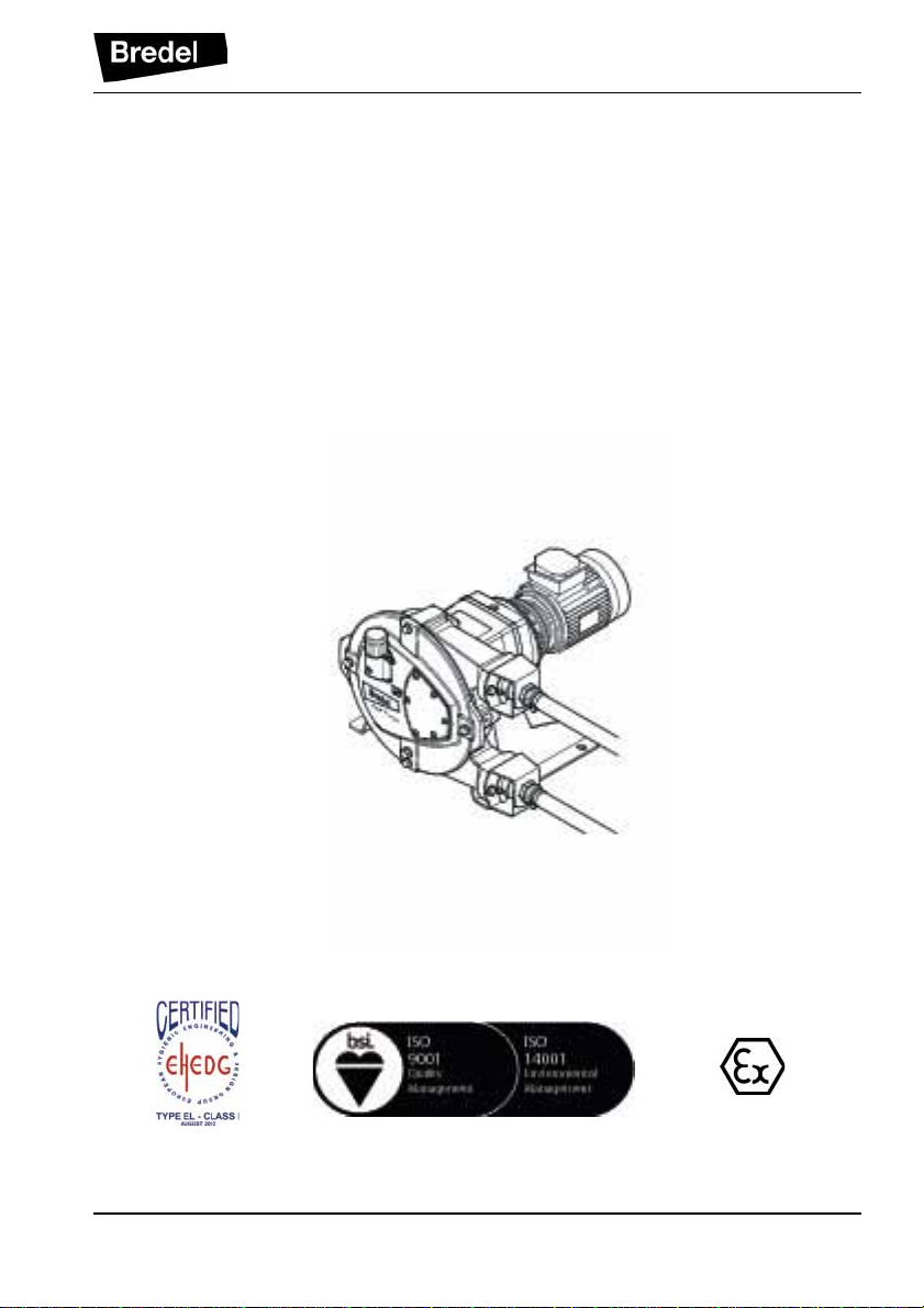
Hose pump series
Bredel 10, Bredel 15 and Bredel 20
Manual
3
Page 4

© 2013 Watson-Marlow Bredel B.V.
All rights reserved.
The information provided herein may not be reproduced and/or published in any form,
by print, photoprint, microfilm or any other means whatsoever (electronically or
mechanically) without the prior written authorisation of Watson-Marlow Bredel B.V.
The information provided can be changed without prior notification. Watson-Marlow
Bredel B.V. or one of its representatives cannot be held liable for possible damage
resulting from use of this manual. This is an extens ive limitation of the liability which
applies to all damage, inclusive of (without limitation) compensating, direct, indirect or
consequential damage, loss of data, income or profit, loss or damage to possessions
and claims of third parties.
Watson-Marlow Bredel B.V. provides the information in this manual "as is" and does not
take any responsibility and does not give any guarantee on this manual or its content.
Watson-Marlow Bredel B.V. rejects all responsibilities and guarantees. Furthermore,
Watson-Marlow Bredel B.V. does not take responsibility for and does not guarantee that
the information in this manual is accurate, complete or up to date.
Names, trade names, brands, etc. used by Watson-Marlow Bredel B.V. may not, as per
the legislation concerning the protection of trade names, be considered as available.
4
Page 5

CONTENTS
1 GENERAL
1.1 How to use this manual .......................................................................... 8
1.2 Original instructions .......................................................... ...... ..... ........... 8
1.3 Other supplied documentation ................................................................ 8
1.4 Service and support ................................................................................ 8
1.5 Environment and disposal of waste ........................................................ 9
2SAFETY
2.1 Symbols ................................................................................................ 10
2.2 Intended use ......................................................................................... 11
2.3 Use in potentially explosive atmospheres ............................................. 11
2.4 Responsibility ........................................................................................ 12
2.5 Qualification of the user ........................................................................ 12
2.6 Regulations and instructions ................................................................. 12
3 WARRANTY CONDITIONS
4 DESCRIPTION
4.1 Identification of the product ................................................................... 14
4.1.1 Identification of the product ....................................................... 14
4.1.2 Identification of the pump .......................................................... 14
4.1.3 Identification of the rotor ............................................................ 14
4.1.4 Identification of the gearbox ...................................................... 15
4.1.5 Identification of the electric mo tor .................... ...... ...... ..... ......... 15
4.1.6 Identification of the frequency controller .................................... 16
4.1.7 Identification of the pump hose ................................................. 16
4.2 Construction of the pump ...................................................................... 17
4.3 Operation of the pump .......................................................................... 17
4.4 Pump hose ............................................................................................ 19
4.4.1 General ...................................................................................... 19
4.4.2 Hose compression force adjustment ......................................... 20
4.4.3 Lubrication and cooling ............................................................. 20
4.5 Gearbox ................................................................................................ 20
4.6 Electric motor ........................................................................................ 21
4.7 Frequency controller ............................................................................. 21
4.8 Available options ................................................................................... 21
5
Page 6

5 INSTALLATION
5.1 Unpacking ............................................................................................ 22
5.2 Inspection ............................................................................................. 22
5.3 Installation conditions ........................................................................... 22
5.3.1 Ambient conditions .................................................................... 22
5.3.2 Set-up ........................................................................................ 22
5.3.3 Pipework ................................................................................... 23
5.3.4 Frequency controller ................................................................. 24
5.4 Lifting and moving the pump ................................................................ 25
5.5 Placing the pump .................................................................................. 25
6 COMMISSIONING
6.1 Preparations ......................................................................................... 26
6.2 Commissioning ..................................................................................... 26
7 MAINTENANCE
7.1 General ................................................................................................. 28
7.2 Maintenance and periodic inspections ................................................. 28
7.3 Additional maintenance in potentially explosive environments ............ 30
7.4 Cleaning the pump hose ...................................................................... 30
7.5 Changing lubricant ............................................................................... 31
7.6 Replacing pump hose ................................. .......................................... 31
7.6.1 Removing pump hose ............................................................... 31
7.6.2 Cleaning the pump head ........................................................... 33
7.6.3 Fitting the pump hose ...................... ..... ..................................... 33
7.7 Exchanging replacement parts ............................................................. 35
7.7.1 Replacing rotor, bearings and seal ring .................................... 35
7.8 Fitting options ....................................................................................... 39
7.8.1 Fitting a high-level float switch .................................................. 39
7.8.2 Revolution counter .................................................................... 40
8 STORAGE
8.1 Hose pump ........................................................................................... 41
8.2 Pump hose ........................................................................................... 41
9 TROUBLESHOOTING
10 HAZARDOUS ENVIRONMENTS (ATEX)
10.1 ATEX compliance ................................................................................. 47
10.2 Identification ......................................................................................... 47
6
Page 7

10.2.1 Pump head ................................................................................ 47
10.2.2 Gearbox ..................................................................................... 48
10.2.3 Electric motor ............................................................................ 48
10.2.4 Frequency controller ....................... ...... ...... ..... ...... .................... 48
11 SPECIFICATIONS
11.1 Pump head ........................................................................................... 49
11.1.1 Performance .............................................................................. 49
11.1.2 Materials .................................................................................... 50
11.1.3 Surface treatment ...................................................................... 51
11.1.4 Lubricant table pump ................................................................. 51
11.1.5 Weights ..................................................................................... 51
11.1.6 Torque figures ........................................................................... 52
11.2 Gearbox ................................................................................................ 52
11.3 Electric motor ........................................................................................ 53
11.4 Variable Frequency Drive (VFD) (optional) ........................................... 53
11.5 Parts list ................................................................................................ 54
11.5.1 Overview ................................................................................... 54
11.5.2 Cover assembly .......................................... ............................... 55
11.5.3 Pump head assembly ................................................................ 56
11.5.4 Support assembly ...................................................................... 57
11.5.5 Barbed nipple assembly (PTFE/PDVF) ..................................... 58
11.5.6 Barbed or threaded nipple assembly (stainless steel) ............... 59
11.5.7 Flange assembly (1) .................................................................. 60
11.5.8 Flange assembly (2) .................................................................. 61
11.5.9 Revolution counter assembly ................................ ...... .............. 62
11.5.10Lubricants ................................................................................. 62
EC DECLARATION OF CONFORMITY OF THE MACHINERY
SAFETY FORM
NOTES
7
Page 8

GENERAL
1 GENERAL
1.1 How to use this manual
This manual is intended as a reference book by means
of which qualified users are able to install, commission
and maintain the hose pumps mentioned on the front
cover.
1.2 Original instructions
The original instructions for this manual have been
written in English. Other language versions of this
manual are a translation of the original instructions.
1.3 Other supplied documentation
Documentation o f co mpone nt s su ch as th e gearb ox, the
motor and the frequency co ntrolle r is not inc luded in this
manual. However, if additional documentation is
supplied, you must follow the instructions in this
additional documen t ati on.
1.4 Service and support
For information with respect to specific adjustments,
installation, maintenance or repair jobs which fall
beyond the scope of this manual, contact your Bredel
representative. Make sure you have the following data
at hand:
• Serial number hose pump
• Article number pump hose
• Article number gearbox
• Article number electric motor
• Article number frequency controller
You will find these data on the identification plates or
stickers of the pumphead, the pump hose, the gearbox
and the electric motor. Refer to § 4.1.1.
8
Page 9

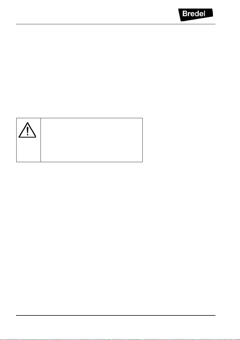
1.5 Environment and disposal of waste
CAUTION
Always observe the local rules and regulations with respect to processing (non reusable) parts of the hose pump.
Enquire within your local government about the
possibilities for reuse or environment-friendly
processing of packaging materials, (contaminated)
lubricant and oil.
GENERAL
9
Page 10
SAFETY
2SAFETY
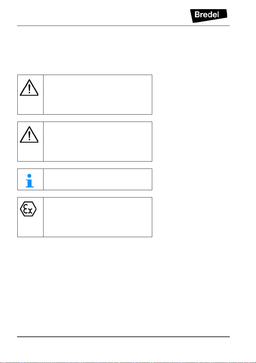
2.1 Symbols
In this manual the following symbols are used:
WARNING
Procedures which, if not carried out with
the necessary care, may resu lt in serious
damage to the hose pump or in serious
bodily harm.
CAUTION
Procedures which, if not carried out with
the necessary care, may resu lt in serious
damage to the hose pum p, the surrounding
area or the environment.
Remarks, suggestions and advice.
10
WARNING
Procedures, remarks, suggestions or
advice which refer to use in potentially
explosive atmos phe res in a ccordance with
the ATEX Directive 94/9/EC.
Page 11

2.2 Intended use
The hose pump is exclusively designed for pumping
suitable products. Every other or further use is not in
conformance with the intended use.
The "Intended use" as laid down in EN 292-1 is "... the
use for which the technical product is intended in
accordance with the specifications of the manufacturer,
inclusive of his indications in the sales brochure". In
case of doubt it is the use which appears to be its
intended use judging from the construction, execution
and function of the product . Observing the i nstructions
in the user's documentation also belongs to intended
use.
Only use the pump in conformance with the intended
use described above. The manufacturer cannot be held
responsible for damage or harm resulting from use that
is not in conformance with the intended use. If you want
to change the application of your hose pump, contact
your Bredel representative first.
2.3 Use in potentially explosive atmospheres
SAFETY
Refer to chapter 10 for a description of pump
configurations th at are suitable in a potentially exp losiv e
atmosphere. Such configurations are suitable for use in
a potentially explosive atmosphere. For use in Europe,
the pump complie s with the European Directi ve 94 /9/EC
(ATEX).
The pumps belong to:
• Group II Appliances, category 2 GD bck T5
Use in Potentially explosive atmospheres
requires special configuration of the pump
unit. Contact y our Bredel rep resentativ e for
use in explosive atmosphe res .
11
Page 12
SAFETY
2.4 Responsibility
The manufacturer does not ac ce pt any resp ons ib ili ty for
damage or harm caused by not (strictly) observing the
safety regulations and instructions in this manual and
the also supplied documentation, or by negligence
during installation, use, maintenance and repair of the
hose pumps mentioned on the front cover. Depending
on the specific working conditions or accessories used,
additional safety instructions can be required.
Immediately contact your Bredel representative, if you
noticed a potential danger while using your hose pump.
WARNING
The user of the hose pump is always fully
responsible for observing the local valid
safety regulations and directives. Observe
these safety regulation s and directives
when using the hose pump.
2.5 Qualification of the user
The installation, use and maintenance of the hose
pump should only be performed by well-trained and
qualified users. Temporary staff and persons in training
may use the hose pump only under the supervision and
responsibility of trained and qualified users.
2.6 Regulations and instructions
• Everyone who works with the hose pump must
be aware of the contents of this manual and
observe the instructions with great car e.
• Never change the order of the actions to be
carried out.
• Always store the manual near the hose pump.
12
Page 13

3 WARRANTY CONDITIONS
The manufacturer offers a two-year warranty on all
parts of the hose pum p. Thi s m ean s th at al l parts will be
repaired or replaced free of charge, with the exception
of consumables, such as pump hoses, hose clamps,
ball bearings, wear rings, and seals, or parts which
have been misused or have been intentionally
damaged.
If parts are used that are not Watson-Marlow Bredel
B.V. (hereafter called Bredel) parts, every warranty
becomes void.
Damaged parts which are covered by the applicable
warranty conditions can be returned to the
manufacturer. The parts must be accompanied by a
fully filled in and signed safety form, as present in the
back of this manual. The safety form must be applied to
the outside of the shipping carton. Parts which have
been contaminated or which have been corroded by
chemicals or other substances which can pose a health
risk, must be cleaned before they are returned to the
manufacturer. Furthermore, it should be indicated on
the safety form which spec ific cleaning procedure has
been followed, and it should be indicated that the
equipment has been decontaminated. The safety form
is required at all items, even if the parts have not been
used.
WARRANTY CONDITIONS
Warranties purporting to be on behalf of Bredel, made
by any person, including representatives of Bredel, its
subsidiaries, or its distributors, which do not accord with
the terms of this warranty shall not be binding upon
Bredel unless expressly approved in writing by a
Director or Manager of Bredel.
13
Page 14
DESCRIPTION
4 DESCRIPTION
4.1 Identification of the product
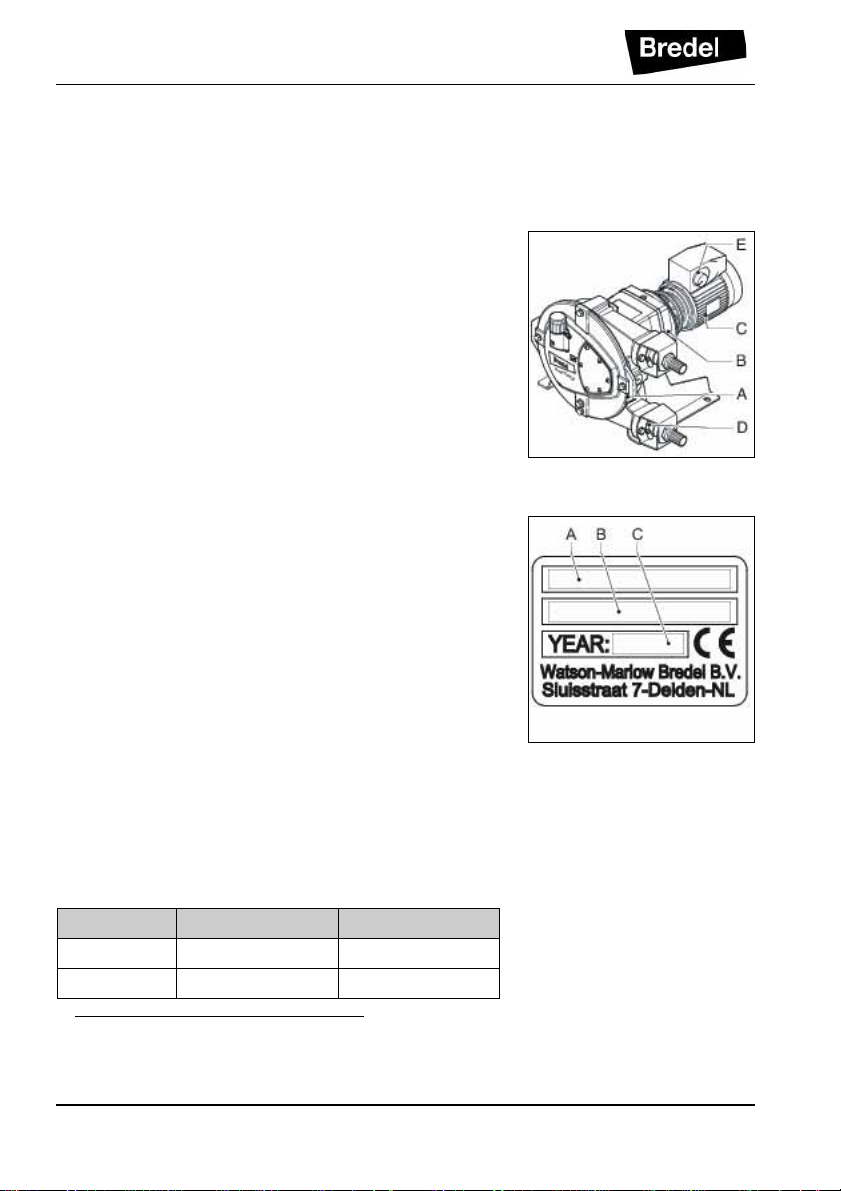
4.1.1 Identification of the product
The hose pump can be identified based on the
identification plates or stickers on:
A: Pump head
B: Gearbox
C: Electric motor
D: Pump hose
E: Frequency controller (option)
4.1.2 Identification of the pump
The identification plate on the pump head contains the
following data:
A: Pump type
B: Serial number and rotor identification letter
1
C: Year of manufacture
4.1.3 Identification of the rotor
The rotor identification letter identifies which type of
rotor is mounted to the pump. The table below shows
the rotor identification letter and the article number of
the mounted rotor. Also refer to 11.5.3.
Letter Bredel 10 Bredel 15-20
blank no rotor no rotor
A 210103L 215103L
1 For information on the rotor identification letter, refer
to 4.1.3.
14
Page 15
Letter Bredel 10 Bredel 15-20
B 210103H 215103H
C - 220103L
D - 220103H
E 210103X 215103X
F - 220103X
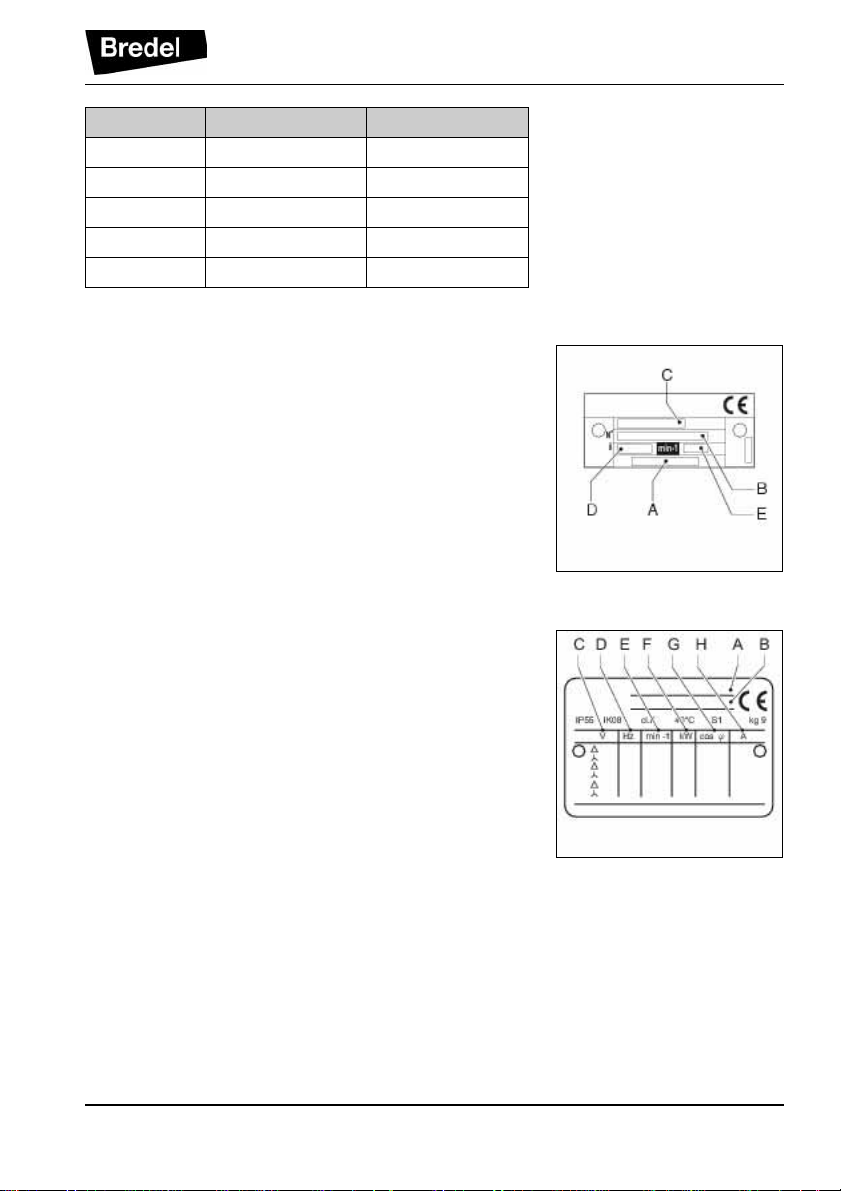
4.1.4 Identification of the gearbox
The identification plate on the gearbox contains the
following data:
A: Article number
B: Serial number
C: Type number
D: Reduction ratio
E: Number of revolutions per minute
4.1.5 Identification of the electric motor
The identification plate on the electric motor contains
the following data:
A: Type number
B: Serial number
C: Article number
D: Mains
E: Frequency
F: Speed
G: Power
H: Power factor
I: Current
DESCRIPTION
15
Page 16
DESCRIPTION
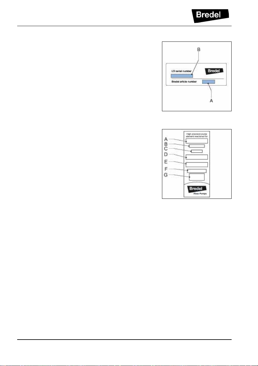
4.1.6 Identification of the frequency controller
The identification of the Bredel Variable Frequency
Drive (VFD) can be found inside the VFD. Remove the
cover by loosening the two screws. The identification
sticker contains the following data:
A: Article number
B: Serial number
4.1.7 Identification of the pump hose
The identification st icker on the pump hose contains the
following data:
A: Pump type
B: Reorder number
C: Internal diameter
D: Type of material of inner liner
E: Remarks, if applicable
F: Maximum permissible working pressure
G: Production code
16
Page 17
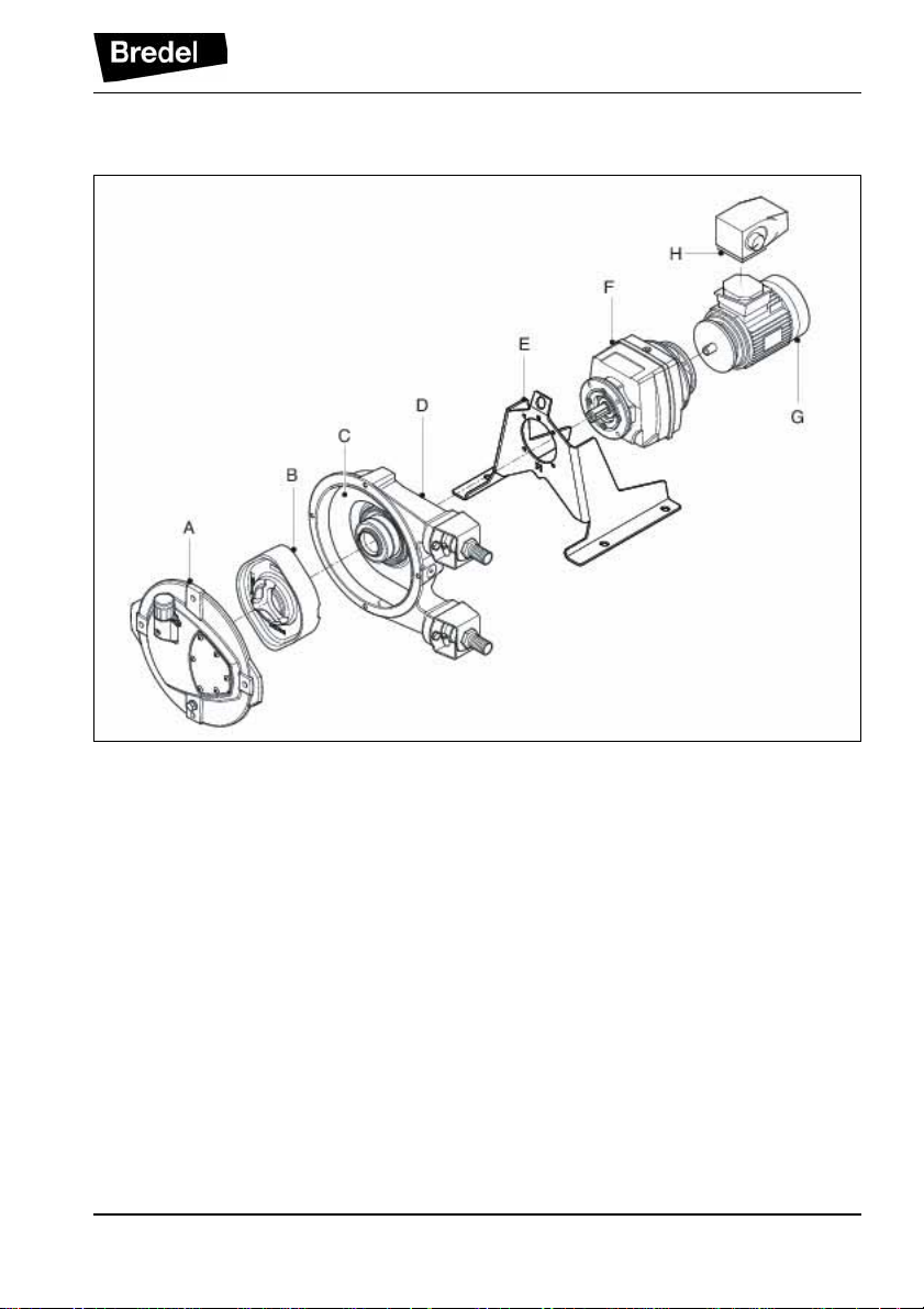
4.2 Construction of the pump
DESCRIPTION
A: Cover
B: Rotor
C: Pump hose
D: Pump housing
E: Support
F: Gearbox
G: Electric motor
H: Frequency controller
4.3 Operation of the pump
The heart of the pump head consists of a specially
constructed pump hose (A) which lies contorted against
the inside of the pump housing (B). Both ends of the
hose are c onnected to the suction and discha rge lines
17
Page 18
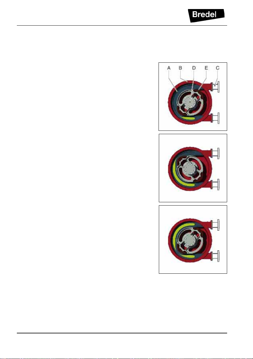
DESCRIPTION
(C). A bearing-mounted rotor (D) with two facing
integral pressing shoes (E) is in the centre of the pump
head.
In phase 1 the lower shoe compresses the pump hose
by the rotational movement of the rotor, forcing the fluid
through the hose. As soon as the shoe has passed, the
hose recovers to its original shape due to the
mechanical properties of the material.
In phase 2 the product is drawn into the hose by the
(continuous) turning motion of the rotor.
In phase 3, the second integral pressing shoe will
subsequently compress the pump hose. Due to the
continuous rotating movement of the rotor not only new
product is sucked in, but also the already present
product is pressed out by the shoe. When the first shoe
runs from the pump hose, the second shoe has already
closed the pump hose and the product is prevented
from flowing back . T his m ethod of liquid displacement is
also known as the "positive displacement principle".
18
Page 19
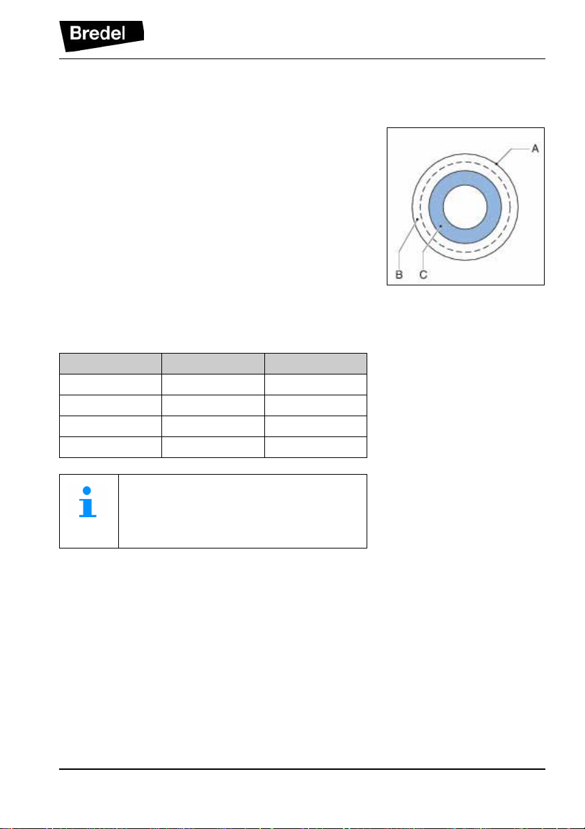
4.4 Pump hose
4.4.1 General A: Outer extruded layer made of natural rubber B: Two nylon reinforcement layers C: Inner extruded liner
The pump hose liner material should be chemically
resistant with the product to be pumped. Dependent on
the specific requirements of your application a
corresponding pump hose must be selected. For each
pump model various hose types are available.
The material of the inner liner of the pump hose
determines the hose type. Each hose type is marked by
a unique colour code.
Hose type Material Colour code
NR Natural rubber Purple
NBR Nitrile rubber Yell ow
EPDM EPDM Red
CSM CSM Blue
DESCRIPTION
Consult your Bredel representative for
more detailed information about the chemical and temperature resistance of pump
hoses.
The Bredel pump hoses have been carefully machined,
therefore there are minimum tolerances in wall
thickness. It is very important to guarantee the cor rect
compression of the pump hose, because:
• When the compression is too high, it creates a
too high load of the pump and pump hose,
which may result in a reduction of the life of the
pump hose and bearings.
19
Page 20

DESCRIPTION
• When the compression is too low, this will result
in loss of capacity and backflow. Backflow
results in a reduction of the life of the pump
hose.
4.4.2 Hose compression force adjustment
The compression force of the pump hose can be
adjusted by installing a rotor with a different dimension
between the tips of the integral pressing shoes. The
rotor is chosen to achieve an optimal life of the pump
hose for the intended us e of th e hos e pu mp . If yo u w ant
to change the application of your hose pump, contact
your Bredel representative .
4.4.3 Lubrication and cooling
The pumphead, in which the rotor and pump hose can
be found, is filled with Bredel Genuine Hose Lubricant.
This lubricant lubricates the movement between the
hose and the pressing shoes and dissipates the
generated heat via the pump housing and the cover.
The lubricant is food grade. See §11.1.4 for the
required quantity an d NSF registration.
Consult your Bredel representative for
lubrication recommendations when operating the hose pump below 2 rpm.
4.5 Gearbox
The hose pump types described in this manual use
helical gearbox units. The gearboxes are fitted with a
flange connection. Refer to § 11.2 for specifications. If
the pump is to be used in potentially explosive
atmospheres, refer to chapter 10.
20
Page 21

4.6 Electric motor
If the electric motor has been standard supplied by the
manufacturer, it is a standardized squirrel-cage motor.
Refer to § 11.3 for specifications. If the pump is to be
used in potentially explosive atmospheres, refer to
chapter 10.
4.7 Frequency controller
Refer to the also s upp lie d documentation of the supplier
and § 11.4. If the pump is to be used in potentially
explosive atmospheres, refer to chapter 10.
4.8 Available options
The following options are available for the hose pump:
• High (lubricant) level float switch
• Revolution counter
• Low, medium, or high pressure rotor
• Rotor and coupling for heavy duty
• Frequency controller
• Special configuration for use in explosive
atmospheres
DESCRIPTION
21
Page 22

INSTALLATION
5 INSTALLATION
5.1 Unpacking
When unpacking carefully follow the instructions as
given on the packaging or on the hose pump.
5.2 Inspection
Check that yo ur deliv ery is c orrect an d check i t for any
transport damage. Refer to § 4.1.1. Report any damage
immediately to your Bredel representative.
5.3 Installation conditions
5.3.1 Ambient conditions
Make sure that the hose pump is in an area where the
ambient temperature during operation is not lower than
-20 °C and not higher than +45 °C.
5.3.2 Set-up
• The pump materials and protective layers are
suitable for indoor set-up and a protected
outdoor set-up. Under certain conditions the
pump is suitable for limited outdoor set-up or a
salty or aggressive atmosphere. Consult your
Bredel representative for more information.
• Make sure that the floor surface is horizontal
and has a maximum slope of 10 mm per metre.
• Make sure that there is sufficient room around
the pump to carry out the necessary
maintenance activitie s.
• Make sure that the room is sufficiently
ventilated, so that the heat developed by the
pump and drive can be discharged. Keep some
distance between the ventilation cover of the
electric motor and wall to enable the supply of
necessary cooling air.
22
Page 23

5.3.3 Pipework
When determining and connecting suction and
discharge lines consider the following points:
• The bore size of the suction and disch arge line s
must be larger than the bore size of the pump
hose. For more information consult your Bredel
representative.
• Limit the presence of sharp bends in the
discharge line. Make sure that the radius of the
bent discharge line is as large as possible
(preferably 5S). It is recommended to use Y-
connections instead of T-connections.
• It is recommended to use a minimum of three
quarters (3/4) of the hose length as flexible
hose in the suction or discharge line. This
avoids the need to remove the connection lines
when changing a pump hose.
• Keep the delivery a nd suction lines as short and
direct as possible.
• Select the correct mounting material for flexible
hoses and make sure that the installation is
suited for the design pressure of the system.
• Prevent any possibilities of exceeding the
maximum worki ng pressure of the ho se pump.
Refer to § 11.1.1. If necessary fit a pressure
relief valve.
INSTALLATION
CAUTION
Consider the maximum permissible working pressure on the discharge side.
Exceeding the ma ximu m wo rking press ure
may lead to serious damage to the pump.
• Make sure that the maximum forces on the
flanges are not exceeded. The permissible
loads are given in the following table.
23
Page 24

INSTALLATION
Maximum permissible loads [N] on the
pump connections
Force Bredel 10 Bredel 15 Bredel 20
F1 600 600 600
F2 300 300 300
F3 120 120 120
5.3.4 Frequency controller
WARNING
A frequency controller that is fitted without
the manual control can start automatically
when power is applied.
If the hose pump is fitted with a frequency controller,
consider the following points:
• Take precautions so the motor does not re-start
automatically af ter an uns ch eduled stop.
In the event of a power or mechanical failure,
the frequency controller controls the motor to
stop. When the cause of the failure is removed,
the motor can restart automatically. The
automatic restart can be dangerous in certain
pump installations.
• All control cables outside the enclosure must be
shielded and have a cross sectional area
between 0.22 and 1 mm
be connected to earth at both ends.
2
. The shielding must
24
Page 25

5.4 Lifting and moving the pump
For lifting and movi ng the hos e pump, the pump s upport
has a lifting eye (A).
The complete hose pump, i.e. pump head, gearbox and
electric motor, must be lifted using the lifting eye plus
additional support using suitably rated straps or
slings (A). For the weights, refer to § 11.1.5.
WARNING
If the pump is to be lifted ensure that all
standard lifting practises are adhered to
and carried out by qualified personnel only.
INSTALLATION
5.5 Placing the pump
Position the pump on a horizontal surface. Use suitable
anchor bolts to attach the pump to the floor surface.
25
Page 26

COMMISSIONING
6 COMMISSIONING
6.1 Preparations
WARNING
A frequency controller that is fitted without
manual control can start the pump auto-
matically when power is applied.
WARNING
Disconnect and lock the power supply to
the pump drive before any work is carried
out.
In case the motor is fitted with a frequency
controller and has a single-phase power
supply, wait two minutes to make sure that
the capacitors have discharged.
1. Connect the electric motor and, if present, the
frequency controller in conformance with the
locally applicab le rules an d regulati ons. Refer to
§ 5.3.4. Have the electrical installation work
carried out by qualified perso nne l.
2. Check that the lubricant level is above the
minimum leve l line in the inspec tion window. If
necessary refill with Bredel Genuine Hose
Lubricant via the breather plug. S ee also § 7.5.
6.2 Commissioning
1. Connect the pipework.
2. Make sure that there are no obstructions such
as closed valves.
3. Switch on the hose pump.
4. Check the rotation of the rotor.
26
Page 27

5. Check the capacity of the hose pump. If the
capacity differs from your specification, follow
the instructions in chapter 9 or consult your
Bredel representative.
6. Check the capacity range of the frequency
controller. In case of any deviations consult the
documentation of the supplier.
7. Check the hose pump in acc orda nc e w it h po in ts
2 to 4 of the maintenance table from §7.2.
COMMISSIONING
27
Page 28

MAINTENANCE
7 MAINTENANCE
7.1 General
WARNING
Disconnect and lock the power supply to
the pump drive before any work is carried
out.
In case the motor is fitted with a frequency
controller and has a single-phase power
supply, wait two minutes to make sure that
the capacitors have discharged.
WARNING
Only use original Bredel parts when maintaining the hose pump. Bredel cannot
guarantee correct operation and any consequential damage that occurs from the
use of non-original Bredel components.
See also chapters 2 and 3.
7.2 Maintenance and periodic inspections
The following maintenance scheme shows the
maintenance and periodic inspection that need to be
carried out on the hose pump to guarantee optimal
safety, operation and life of the pump.
28
Page 29

MAINTENANCE
Point Action To be carried out Remark
1 Check the lubricant
level.
Before startup of the
pump and on a scheduled interval duri ng o peration.
Make sure that the lubricant level is above the
minimum level lin e in the
inspection window.
If necessary refill the
lubricant. See also § 7.5.
2 Check the pump head
for any leakage of lubricant around the cover,
the brackets an d the rear
Before startup of the
pump and on a scheduled interval duri ng o peration.
See § 9.
of the pump head.
3 Check the gearbox for
any leakage.
Before startup of the
pump and on a scheduled interval duri ng o per-
In case of leakage consult your Bredel representative.
ation.
4 Check pump for deviat-
ing temperature or
On a scheduled interval
during operation.
See § 9.
strange noises.
5 Check rotor with integral
pressing shoes for
When replacing the
pump hose.
See § 7.6.
excessive wear.
6 Internal cleaning of the
pump hose.
7 Replacing pump hose. Preventive, this means
Cleaning of the system
or product change.
See § 7.4.
See § 7.6.
after 75% of the hose li fe
of the first hose.
8 Changing lubricant. After every 2
nd
hose
See § 7.5
change or after 5,000
service hours, whic hever
comes first or after hose
rupture.
9 Replacing seal ring. If necessary. See § 7.7.1.
29
Page 30

MAINTENANCE
Point Action To be carried out Remark
10 Replacing rotor with i nte-
gral pressing shoes.
11 Replacing bearings. If necessary. See § 7.7.1.
7.3 Additional maintenance in potentially explosive environments
The following maintenance scheme shows the
additional maintenance and periodic inspections that
need to be carried out on the hose pump to guarantee
an optimal safety, operation and life of the pump in a
potentially explosive environment.
Point Action To be carried out Remark
1 Replacing bearings. According to ATEX regu-
2 Cleaning the hose
pump.
Wear on the runni ng s urface of the pump hose
and/or seal ring.
See § 7.7.1.
lations after 40,000 hrs.
service or wh en damage is suspected.
In potentially explosive
(dust) atmospheres, the
dust must be removed
regularly.
7.4 Cleaning the pump hose
The inside of the pump hose can be easily cleaned by
rinsing the pump with clean water. If a cleaning fluid is
added to the water, check if the hose liner material is
resistant to it. Also check if the pump hose can resist
the cleaning temperature. Special cleaning balls are
also available. Contact your Bredel representative for
more details.
30
Page 31

7.5 Changing lubricant
1. Place a tray (A) under the drain plug in the
cover of the pu mp. Remove the dr ain plug (B) .
Catch the lubricant from the pump housing in
the tray. Position the drain plug and tighten it
firmly.
2. The pump housing can be filled with lubricant
via the breather (A) on the cover. For this
purpose remove the breather cap (B) and
position a funnel (C) in the breather. Pour the
lubricant in the pump housing via the funnel.
3. Keep on pouring until the lubricant level has
risen above the level line in the inspection
window. Place breather cap.
MAINTENANCE
For the required quantity of lubricant, refer
to § 11.1.4.
7.6 Replacing pump hose
7.6.1 Removing pump hose
1. Isolate the pump from the electrical supply.
2. Close any shut-off valves in both the suction
and discharge line to minimize product loss.
31
Page 32

MAINTENANCE
3. Place a tray (A) under the drain plug in the
bottom of the pump head. The tray must be
large enough to contain the lubricant, possibly
contaminated with product fluid, from the pump
head. Remove the drain plug (B). Catch the
lubricant from the pump housing in the tray.
Check that th e breather mounted on the cover
is not obscured. Position the drain plug and
tighten it firmly.
4. Disconnect the suction and discharge lines.
5. Loosen hose clamp (A) of both the inlet and
outlet ports by loosening bolt (B).
6. Loosen the retaining bolts (A) of the bracket (B)
and remove the bolts.
7. Pull the bracket and hose clamp from the hose.
Then pull off the rubber bush (C).
Do steps 6 to 7 both for the inlet and outlet
ports.
8. Switch on the electrical supply.
9. Power out the hose (A) from the pump chamber
by jogging the drive mot or.
WARNING
During jogging the drive:
- Do not stand in front of the pump
ports.
- Do not try to guide the hose by
hand.
32
Page 33

7.6.2 Cleaning the pump head
1. Isolate the pump from the electrical supply.
2. Remove the cover (B) by loosening the
retaining bolts (A).
3. Check the gasket (C) and replace it if
necessary.
4. Rinse the pump head with clean water and
remove all residues. Make sure that no rinsing
water remains in the pump head.
5. Check the rotor for wear or d am age a nd replace
the rotor if necessary. Also see the mainten ance
scheme in § 7.2.
CAUTION
When the rotor is worn the compression
force of the hose decreases. If the compression force is too low, this results in a
loss of capacity by the ba c kflow of the liquid to be pumped.
Backflow result s in a reduct ion of the life of
the pump hose.
MAINTENANCE
6. Replace the cover and fasten the retaining bolts
with the correct torque. Refer to § 11.1.6.
7. Switch on the electrical supply to the pump.
7.6.3 Fitting the pump hose
1. Clean the (new) pump hose on the outside and
fully lubricate it with Bredel Genuine Hose
Lubricant.
33
Page 34

MAINTENANCE
2. Fit the pump hose (A) via one of the ports.
3. Let the motor run to let the rotor pull the hose in
the pump housing. Stop the motor when the
hose sticks out equally from both sides of the
pump housing.
WARNING
During jogging the drive:
- Do not stand in front of the pump
ports.
- Do not try to guide the hose by
hand.
4. Check that the rubber bushes (A) are not
deformed or damaged and replace them if
necessary.
5. Check that the hose clamps (B) are not
damaged and replace them if necessary.
6. First fit the inlet port.
Slide the rubber bush (D) over the hose.
Push the bracket (A) and the hose clamp (B)
over the hose together. Align the holes in the
bracket with the ones at the front of the port.
Position the two retaining bolts (C) and tighten
them. Make sure th e bolt s are tighte ned with the
correct torque. Refer to § 11.1.6.
34
Page 35

7. Turn the rotor in such a way that the hose (A) is
pressed firmly against the bracket (B).
8. Tighten the bolt (A) of the hos e cla mp (B). M ak e
sure the bolt is tight ened w ith th e correct t orqu e.
Refer to § 11.1.6.
9. Now fit the other port. For this port proceed in
the same way as described above for the inlet
port.
10. Fill the pump housing with Bredel Genuine
Hose Lubricant. Refer to §7.5.
11. Connect the suction and discharge lines.
MAINTENANCE
7.7 Exchanging replacement parts
7.7.1 Replacing rotor, bearings and seal ring
1. Remove the pump hose. Refer to § 7.6.1.
2. Isolate the pump from the electrical supply.
3. Remove the cover (B) by loosening the
retaining bolts (A).
4. Check the gasket (C) and replace it if
necessary.
35
Page 36

MAINTENANCE
5. Put the hose pump on blocks. Make sure the
space between the blocks is wide enough for
the rotor to fall.
6. Remove the nuts (B), the washers (C) and the
pump drive (A).
7. Put a plastic or wooden drive pin (A) on the
rotor.
8. Hit the drive pin firmly with a hammer to remove
the rotor.
9. Put the hose pump upright on the support.
10. Dismount the circlip (A) with the correct tool.
36
Page 37

11. Dismount the bearings (A), the spac er ring (B)
and the retaining ring (C) with the correct tool.
Clean the hub.
12. Remove the seal ring (A). Clean and degrease
the bore.
13. Fit a new seal ring (A) using good engineering
practises. The seal ring must be fitted in the
correct orie ntati on (B ). Ma ke sur e that th e open
side points to the pump cover.
MAINTENANCE
14. Slightly oil the inner ring of the (new) bearings
and the seat on the hub. Fit the bearings and
the rings.
The bearings are pl ac ed on th e hub with a slight
interference fit. Use a pressing tool to press the
bearings on the hub.
37
Page 38

MAINTENANCE
15. Mount the circlip (A).
16. Fit the rotor (A). The rotor is placed on the
bearings with a loose fit. Press the rotor on the
hub until it clicks on the retaining ring.
17. Put the hose pump on two blocks.
18. Fit the pump drive (A) with the nuts (B) and
washers (C). Tighten to the specified torque
settings. Refer to § 11.1.6.
19. Put the hose pump upright on the support.
20. Check the position of the rotor. If necessary
press the rotor on the hub until it clicks on the
retaining ring.
21. Refit the cover (B). Make sure that the 4 bolts
(A) are refitted and that they are tightened in the
correct order, diagonally opposite each other.
Refer to § 11.1.6.
22. Switch on the electrical supply to the pump.
23. Fit the (new) pump hose. Refer to § 7.6.3.
38
Page 39

7.8 Fitting options
7.8.1 Fitting a high-level float switch
1. Dismount the standard breather (A) on the
cover of the pump head.
2. Mount the breather (A) with high-level float
switch.
MAINTENANCE
3. Connect the high-level float switch to the
auxiliary power circuit via the 2-metre long PVC
cable (2 x 0.34mm2). Bear in mind that the
electrical contact of the float switch is normally
closed (NC). The knob is upwards for normally
closed operation. When the lubricant level is
(too) high the contact will open.
Specifications
*
Voltage: Max. 230 V AC/DC
Current: Max. 2 A
Power: Max. 40 VA
* For use in non-explosive atmospheres
39
Page 40

MAINTENANCE
Where the float switch is constructed to
stop the equipment, operating has to be
arranged so that the stop function locks
out, preventing the equipment from being
re-started without re-setting. Check if the
float switch is mounted with the NC si gn a t
the top.
7.8.2 Revolution counter
For feedback of the pump revolutions to an "intelligent"
system, the pump can be provided with an inductive
sensor (A). This sensor is mounted between the two
ports.
Connection of the revolution counter:
The speed sensor can be connected via the 2 meter
long PVC cable (3x 0.34 mm
2
).
Specifications
*
Volt ag e: 10...65 V DC
Current: Max. 200 mA
* For use in non-explosive atmospheres
Adjustment sensor:
The sensor (A) must be adjusted at an offset of 0.75-
1.25 mm to the rotor (B).
40
Page 41

8 STORAGE
8.1 Hose pump
• Store the hose pump and pump parts in a dry
area. Make sure that the hose pump and pump
parts are not exposed to temperatures lower
than -40 °C or higher than +70 °C.
• Cover the openings of the inlet and outlet ports.
• Prevent corrosion of untreated parts. For this
purpose use the correct protection or
packaging.
• After a long period of standstill or storage, the
static load on the pump hose may have caused
permanent deformation, which will reduce the
life of the pump hose. To prevent this, remove
the pump hose when the pu mp is not to b e used
for a period.
8.2 Pump hose
• Store the pump hose in a cool and dark room.
After two years th e hose materi al will age, w hich
will reduce the life of the hose.
STORAGE
41
Page 42

TROUBLESHOOTING
9 TROUBLESHOOTING
WARNING
Disconnect and loc k the power s upply to the pump drive bef ore any w ork is
carried out.
In case the motor is fitted with a frequency controller and has a singlephase power supply, wait two minutes to make sure that the capacitors
have discharged.
If the hose pump does not function (correctly), consult the following checklist to see if
you can remedy the error yourself. If this is not the case, contact your Bredel
representative.
Problem Possible cause Correction
Failure to operate. No voltage. Check that the supply
power switch is on.
Check the electrical sup-
ply is available at the
pump.
Stalled rotor. Check if the pump is
stalled by incorrect fitt ing of
the hose.
Lubricant level monitoring
system has been ac tivate d.
Check that the lubricant
level monitoring system
has stalled the pump.
Check the functioning of
the lubricant level monitoring system, or check the
lubricant level.
42
Page 43

TROUBLESHOOTING
Problem Possible cause Correction
High pump temperature. Non standard hose lubri-
cant used.
Low lubricant level. Add Bredel Genuine Hose
Consult the Bredel representative for the correct
lubricant.
Lubricant. For the required
amount of lubricant refer to
§ 11.1.4.
Product temperature too
high.
Internal friction on the hose
caused by blocked or poor
suction characteristics.
High pump speed. Reduce pump speed to a
Consult the Bredel representative about the maximum temperature rang e of
the product.
Check pipework/valves for
blockages. Ensure that the
suction pipework is as
short as poss ible and that
the diameter is large
enough.
minimum. Consult with
your Bredel pump representative for advice on
optimum pump speeds .
43
Page 44

TROUBLESHOOTING
Problem Possible cause Correction
Low capacity / pressure. Shut-off valve in th e suc-
tion line (partly) closed.
Fully open the shut-off
valve.
Hose rupture or badly worn
hose.
(Partial) blockage of the
suction line or too little
product on the suction
side.
Connections and hose
clamps not correctly
mounted, which ma kes the
pump suck air.
The filling degree of the
pump hose is too low,
because the speed is too
high in relation to the viscosity of the product to be
pumped and the inlet pressure.
The suction line can be too
long or too narrow or a
combination of these factors.
Replace hose. Refer to
§ 7.6.
Ensure that the suction line
is clear of blockages and
that sufficient product is
available.
Tighten connections and
hose clamps.
Consult your Bredel representative for a recommendation.
44
Page 45

TROUBLESHOOTING
Problem Possible cause Correction
Vibration of the pump
and pipework.
Suction and discharge
lines are not secured correctly.
Check and secure pipework.
High pump speed with long
suction and discharge lines
or high relative dens ity or a
combination of these factors.
Too narrow diameter of
suction and/or discharge
line.
Short hose life. Chemical attack of the
hose.
High pump speed. Reduce pump speed.
High discharge pressures.
The hose life is reduced
significantly when the hose
has to suffer high working
pressures. The higher the
working pressure, the more
the hose life is reduced.
Reduce pump speed.
Reduce the line lengths on
both suction and discharge where possible.
Consult your Bredel representative for a recommendation.
Increase the diameter of
the suction/disc ha rge lines.
Check the compatibility of
the hose material with the
product to be pumped.
Consult your Bredel representative for correct hose
selection.
The maximum worki ng
pressure depends on the
hose type. Refer to 11.1.1.
Check that the discharge
line is not blocked, the
shut-off valve s are fully
opened and the pressure
relief valve functions properly (if present in the discharge line).
High product temperature. Consult your Bredel repre-
sentative for correct hose
selection.
High pulsations. Restructure the discharge
and inlet conditions.
45
Page 46

TROUBLESHOOTING
Problem Possible cause Correction
Hose pulled into the
pump.
Insufficient or no hose
lubricant in the pump head.
Add extra lubricant. Refer
to § 7.5.
Lubricant leakage at
bracket.
Leakage from the rear of
the pump housing
"Buffer zone".
Incorrect lubricant: no
Bredel Genuine Hose
Lubricant in the pump
head.
Extremely high inlet pressure - larger than 200 kPa.
Hose blocked by an in co mpressible object in the
hose. The hose cannot be
compressed and will be
pulled into the pump housing.
Bolts of bracket loose. Tighten to the specified
Bolts of hose clam ps loos e. Tighten to the specified
Damaged seal ring. Replace seal ring.
Consult the Bredel representative for the correct
lubricant.
Reduce the inlet pressure.
Remove hose, check for
blockages and replace if
necessary.
torque settings. Refer to
§ 11.1.6.
torque settings. Refer to
§ 11.1.6.
46
Page 47

HAZARDOUS ENVIRONMENTS (ATEX)
10 HAZARDOUS ENVIRONMENTS (ATEX)
10.1 ATEX compliance
Hose pumps that are configured for use in potentially
explosive en vi ro nm en ts co mply to CE di re ct i ve 94/9 / EC
(ATEX directive). The hose pumps as mentioned on the
front cover comply to: Group II Appliances, category
2 GD. Refer to § 10.2.1 for a more detailed definition.
10.2 Identification
10.2.1 Pump head
Hose pumps that are configured for use in potentially
explosive environments are identified by an extra ATEX
plate on the rear of the pump head on one of the ports.
The plate contains the following data:
A ATEX code
B ATEX document number
C year of manufactu re
The following table explains the ATEX code on the
ATEX plate.
II Group II equipment for use in potentially
explosive atmospheres, other than mines
susceptible to firedamp.
2 Category 2 equipment for the requisite level
of protection, even if frequently occurring disturbances or equipment faults have to be
taken into account.
G Equipment for use in expl osive atm osphe res
caused by gases, vapours or mists.
D Equipment for use in explosive atmospheres
caused by dusts.
k Equipment protected by liquid immersion.
c Equipment protected by constructional
safety.
b Equipment protected by control of ignition
source.
47
Page 48

HAZARDOUS ENVIRONMENTS (ATEX)
T5 Classification for Group II G equipment con-
cerning the maximum surface tempe rature.
T90°C Maximum surface temperature for Group II D
equipment, according to thermal test (EN
13463).
10.2.2 Gearbox
The gearbox must be selected to meet your
requirements concerning ATEX. Please contact your
Bredel representative.
10.2.3 Electric motor
The electric motor must be selected to meet your
requirements concerning ATEX. Please contact your
Bredel representative.
10.2.4 Frequency controller
The frequency controller must be selected to meet your
requirements concerning ATEX. Please contact your
Bredel representative.
48
Page 49

SPECIFICATIONS
11 SPECIFICATIONS
11.1 Pump head
11.1.1 Performance
Description Bredel 10 Bredel 15 Bredel 20
Hose inner diameter [mm] 10 15 19
3
Max. capacity, continuous [m
Max. capacity, intermittent [m
/h] 0.11 0.38 0.62
3
*
/h]
0.16 0.60 1.09
Capacity per revolution [l/rev] 0.022 0.083 0.152
Permissible ambient temperature [°C] -20 to +45
Permissible product temperature [°C] -10 to +80
Sound level at 1 m [dB(A)] 60
* Intermittent duty: "Let the pump stand still to cool down for at least 1 hour after 2 hours of
operation".
Maximum working pressure [kPa]
Description Bredel 10 Bredel 15 Bredel 20
Rotor pres sur e
Low Medium High Low Medium High Low Medium High
range
Hose
type
NR 400 800 1200 400 800 1200 400 800 1000
NBR 400 800 1200 400 800 1200 400 800 1000
EPDM 400 800 1000 400 800 1000 400 800 1000
CSM 400 800 1000 400 800 1000 400 800 1000
49
Page 50

SPECIFICATIONS
11.1.2 Materials
Pos Description Material
1 Pump housing Cast-iron
2 Cover Cast-iron
3 Pump rotor Cast-iron
4 Pump support Galvanised steel (AI SI 316 optional)
5 Bracket AISI 316
6 Fasteners AISI 316
7 Seals, gaskets NBR
8 Seals, gaskets EPDM
9 Coupling Steel
50
Page 51

SPECIFICATIONS
11.1.3 Surface treatment
• After surface preparation, one layer of two-component acrylate is used for
surface protection. Standard colour is RAL 3011, however other colours are
optional. Contact your Bredel representative for details on surface treatment.
• All galvanised parts have been provided with an electrolytic zinc layer of 15 - 20
microns.
11.1.4 Lubricant table pump
Bredel 10 Bredel 15 - 20
Lubricant Bredel Genuine
Hose Lubricant
Required quantity [litres] 0.25 0.5
Bredel Genuine Hose Lubricant is registered at NSF: NSF Registration N
Category Code H1. See also: www.NSF.org/USDA.
Should you require additional information with respect to the safety data
sheet, consult your Bredel representative.
11.1.5 Weights
Bredel Genuine
Hose Lubricant
o
123204;
Description Weight [kg]
Bredel 10 Bredel 15 - 20
Pump head (inclusive of hose, lubricant and
pump support)
Pump support 1.8 2.4
Hose 0.4 0.8
Lubricant 0.3 0.6
Pump cover (comple te) 2.3 6.0
Coupling 0.4 0.4
Gearbox GA52... 9.5 9.0
GA53... 10 10
Electric motor 4.5 6.5
12.2 18.5
51
Page 52

SPECIFICATIONS
11.1.6 Torque figures
Pos Description Torques [Nm]
Bredel 10 Bredel 15 - 20
A Cover 10 25
B Hose clamp 3 3
C Bracket 10 25
D Support 10 10
E Inspection window 1.5 1.5
11.2 Gearbox
Type Co-axial gearbox with h elic al gea rs
Number of stages Two or three
Lubrication Lubricated for life
52
Page 53

SPECIFICATIONS
Mounting position IM 2001 (IM B5) flanged gearbox with keyed shaft in hori-
zontal position.
Motor adapter Electric motor has been integrated in the gearbox hou si ng,
by which the smallest possible dimension is achieved.
Optional motor adapter Adapters in conformance with IEC-B5 or NEMA TC.
11.3 Electric motor
Standard electric motor design is an enclosed three-phase asynchronous motor. A
thermal safety device to prevent motor overload is optional.
In case of doubt ab out the l oc al a pp lic ab le regulations for the drive connection, contact your Bredel representative.
Protection class IP55/I K08
Insulation class F
Increase in temperature Within class B
Voltage/frequency 230/400 V - 3 phases - 50 Hz
11.4 Variable Frequency Drive (VFD) (optional)
The Bredel Variable Frequency Drive (VFD) has been preprogrammed and only needs
to be connected to the mains.
RFI filter Integrated RFI filter B (industrial applications).
Control Manual control for setting the speed and the keys for starting
forward, stop and starting reverse.
Protection class IP65
Mains power su pply There are thr ee types available; the ch oice depends on the
local electricity grid:
• 200-240 V ± 10%; 50/60 Hz ± 5%; 1 ph
• 200-240 V ± 10%; 50/60 Hz ± 5%; 3 ph
• 400-480 V ± 10%; 50/60 Hz ± 5%; 3 ph
53
Page 54

SPECIFICATIONS
11.5 Parts list
11.5.1 Overview
Pos. Description
1 Cover assembly. Refer to § 11.5.2.
2 Pump head assembly. Refer to § 11.5.3.
3 Pump support assembly. Refer to § 11.5.4.
4 Barbed nipple assembly. Refer to § 11.5.5.
5 Threaded nipple assembly. Refer to § 11.5.6.
6 Flange assembly (1). Refer to § 11.5.8.
7 Flange assembly (2). Refer to § 11.5.7.
8 Lubricant. Refer to § 11.5.10.
54
Page 55

SPECIFICATIONS
11.5.2 Cover assembly
Pos. Qty. Description Bredel 10 Bredel 15 Bredel 20
1 1 Co ver 210102 215102 215102
2 2 Bolt, hex. head F504038 - -
4 - F504055 F504055
3 2 Washer F523010 - -
4 - F523012 F523012
4 1 Drain pl ug F9 11502 F911502 F911502
5 1 Gasket F342019 F342019 F342019
6 1 Insp ec tion window 210155 215155 215155
7 1 Gas ket 210156 215156 215156
8 3 Round head screw F552535 - -
6 - F552535 F552535
9 1 Breather 29093146 29093146 29093146
10 1 Gasket 29056334 29056334 29056334
11 1 Round head screw F552541 F552541 F552541
12 1 Sticker 210238 215238 220238
55
Page 56

SPECIFICATIONS
11.5.3 Pump head assembly
Pos. Qty. Description Bredel 10 Bredel 15 Bredel 20
1 1 Hose NR 010020 015020 020020
1 Hose NBR 010040 015040 020040
1 Hose EPDM 010075 015075 020075
1 Hose CSM 01007 0 015070 020070
2 1 Pump housing 210101 215101 215101
3 1 Gasket 210123 21 5123 215123
4 1 Rotor, low pressure 210103L 215103L 220103L
Rotor, medium pressure 210103H 215103H 220103H
Rotor, high pressure 210103X 215103X 220103X
5 1 Seal ring S211811 S211811 S211811
6 2 Bearing B141060 B141060 B141060
7 1 Spacer ring 29070201 29070201 29070201
8 1 Retaining ring 29080297 29080297 29080297
9 1 Circlip F343043 F343043 F343043
10 4 Stud F511001 F511001 F511001
56
Page 57

SPECIFICATIONS
Pos. Qty. Description Bredel 10 Bredel 15 Bredel 20
11 1 Coupling, ∅ 20 x 63 mm 29063255 29063255 29063255
Coupling, ∅ 20 x 68 mm 29068255 29068255 29068255
Coupling, ∅ 25 x 63 mm 29064255 29064255 29064255
Coupling, ∅ 25 x 68 mm 29069255 29069255 29069255
11.5.4 Support assembly
Pos. Qty. Description Bredel 10 Bredel 15 Bredel 20
1 1 Pum p sup port 210106 2151 06 215106
2 4 Nut, hex. head F516010 F516010 F516010
3 4 Washer F532008 F532008 F532008
4 1 Screw, countersunk head F507040 F507040 F507040
57
Page 58

SPECIFICATIONS
11.5.5 Barbed nipple assembly (PTFE/PDVF)
Pos. Qty. Description Bredel 10 Bredel 15 Bredel 20
1 2 Rubber bush 210119 215119 215119
2 2 Hose cl am p C112507 C112508 C112508
3 2 Barbe d nipple PTFE 21068801 0 215688015 215688020
Barbed nipple PVDF 210 69 0010 215690015 215690020
4 2 Brac ket 210197 215197 215197
5 4 Bolt, Hex. head F504036 F504054 F504054
6 4 Washer F532008 F532009 F532009
58
Page 59

SPECIFICATIONS
11.5.6 Barbed or threaded nipple assembly (stainless steel)
Pos. Qty. Description Bredel 10 Bredel 15 Bredel 20
1 2 Ru bbe r bush 210 119 215119 215119
2 2 Ho se clamp C112507 C112508 C112508
3 2 Brac ket 210197 215197 215197
4 4 Bolt, Hex. head F504036 F504054 F504054
5 4 Washer F532008 F532009 F532009
6 2 Thre ade d ni pple (BSP) SS 210693010 215693015 215693 020
Barbed nipple SS 210686010 215686015 215686020
Threaded nipple DIN 11851 SS210702010 215702015 215702020
Threaded nipple (NPT) PP 210696010 215696015 215696020
Threaded nipple (NPT) PVC 210697010 215697015 215697020
Threaded nipple (NPT) SS 210698010 215698015 215698020
59
Page 60

SPECIFICATIONS
11.5.7 Flange assembly (1)
Pos. Qty. Description Bredel 10 Bredel 15 Bredel 20
1 2 Rubber bush 210119 215119 215119
2 2 Hose cl am p C112507 C112508 C112508
3 2 Brac ket 210197 215197 215197
4 4 Bolt, Hex. head F504036 F504054 F504054
5 4 Washer F532008 F532009 F532009
6 2 Thre ade d ni pple (BSP) SS 210693010 215693015 215693020
7 2 Nut F519003 F519004 F519004
8 2 Flange D IN SS A304504 A 304505 A304505
2 Flange ASA SS A305504 A305505 A30 5505
60
Page 61

SPECIFICATIONS
11.5.8 Flange assembly (2)
Pos. Qty. Description Bredel 10 Bredel 15 Bredel 20
1 2 Ru bbe r bush 210 119 215119 215119
2 2 Ho se clamp C112507 C112508 C112508
3 2 Flange bracket 210197A 215197A 215197A
4 4 Bolt, Hex. head F504036 F504054 F504054
5 4 Washer F532008 F532009 F532009
6 2 Flange ASA 210199A 215199A 215199A
7 2 Insert PP 21018 9 2 15189 220189
61
Page 62

SPECIFICATIONS
11.5.9 Revolution counter assembly
Pos. Qty Description Bredel 10 Bredel 15 Bredel 20
1 1 Pum p housing 210101A 215 101 A 215101A
2 1 Revol ut i on c ounter 29060367 29060367 29060367
3 1 Gasket ring F724009 F724009 F724009
11.5.10 Lubricants
Pos. Qty. Description Bredel 10 Bredel 15 Bredel 20
- 1 0.5 l can Bredel Genuine
Hose Lubricant
901143 901143 901143
62
Page 63

ORIGINAL
EC Declaration of Co nformity for machinery
EC DECLARATION OF CONFORMITY OF THE MACHINERY
(according to Annex II.1.A. of Directive 2006/42/EC on machinery)
We,
Watson-Marlow Bredel B.V.
Sluisstraat 7
P.O. Box 47
7490 AA Delden
The Netherlands,
herewith declare, on our own responsibility, that the following machinery fulfils all the
relevant provisions of Directive 2006/42/EC:
Peristaltic hose pump: Bredel 10-20 series,
for the transportation of various kinds of fluids.
In addition, the machi nery compl ies wi th the ha rmoni sed st an dard(s) , ot her st and ards o r
technical specifications, applicable requirements of these standards and/or
specifications as listed below:
NEN-EN 809
NEN-EN-ISO 12100-2
NEN-EN-IEC 60204-1
The undersigned is responsible for compilation of the technical file and makes this
declaration on behalf of the manufacturer.
J. van den Heuvel
Managing Director
The Netherlands, Delden
1 June 2013
63
Page 64

SAFETY FORM
Safety form
SAFETY FORM
Product Use and Decontamination Declaratio n
In compliance with the Health and Safety Regulations, the user is required to declare those substances that
have been in contact with the item(s) you are returning to Watson-Marlow Bredel B.V. or any of its subsidiaries or
distributors. Failure to do so will cause delays in servicing the item or in issuing a response. Therefore, please
complete this form to make sure we have the information before receipt of the item(s) being returned. A completed copy must be attached to the outside of the packaging containing the item(s). You, the user, are responsible for cleaning and decontaminating the item(s) before returning them.
Please complete a separate Decontamination Certificate for each item returned. RGA/KBR no...................
1 Company ............................................................. .........................................................................................
Address ................. ........... .......... ........... .......... ..... .................... ..... ........... .......... ...........................................
Postal code...........................................................
Telephone .............................................................
2 Product ................................................................ 3.4 Cleaning fluid to be used if residue of chemical is
2.1 Serial Number ......................................................
2.2 Has the Product been used?
YES NO
If yes, please complete all the following para-
graphs.
If no, please complete paragraph 5 only
3 Details of substances pumped 4 I hereby confirm that the only substances(s) that
3.1 Chemical Names
a) ...................... ................ ............... ................ .....
b) ...................... ................ ............... ................ .....
c) ...................... ............................... .....................
d) ...................... ................ ............... ................ .....
3.2 Precautions to be taken in handling these substances:
a) ...................... ................ ............... ................ .....
b) ...................... ................ ............... ................ .....
c) ...................... ............................... .....................
d) ...................... ................ ............... ................ .....
3.3 Action to be taken in the event of human contact:
a) .........................................................................
b) .........................................................................
c) .........................................................................
d) .........................................................................
Fax number ..........................................................
found during servicing;
a) ........................................................................
b) ........................................................................
c) ................................................... ...... ..... ..... .....
d) ........................................................................
the equipment specified has pumped or come into
contact w it h a r e t h ose na me d , th at t h e in f or ma t ion
given is correct, and the carrier has been informed
if the consignment is of a hazardous nature.
5 Signed .................................................. ...............
Name ......................... ........................... ...............
Position ...................... ...... ..... ..... ..... .....................
Date ...................... .......................... .....................
Note:
To assist us in our servicing please describe
any fault condition you ha ve witn essed.
.............................................................................
.............................................................................
.............................................................................
.............................................................................
.............................................................................
Page 65

Notes
NOTES
NOTES
65
Page 66

NOTES
66
Page 67

NOTES
67
Page 68

Watson-Marlow Bredel B.V.
P.O. Box 47
NL-7490 AA Delden
The Netherlands
Telephone: +31 (0)74 3770000
Fax: +31 (0)74 3761175
E-mail: bredel@wmpg.com
Internet: http://www.bredel.com
68
29210309 TS04-026-C
© 2013 Watson-Marlow Bredel B.V.
 Loading...