

Page 1

Disc
The disc inserted in the front cover contains the user manual of the models APEX10,
APEX15 and APEX20. The user manual is available in the following languages:
The disc also contains quick-reference instructions for the replacement of the pump
hose. This replacement instruction is only for users that are familiar with the
replacement procedures in the user manual.
How to use the disc
1 Put the disc in the disc drive.
2 Close the disc drive.
The disc will start automatically.
3 Wait until the various language versions appear on screen.
4 Select the required language (click 1x with the left mouse button).
The PDF reader program will automatically start and the required user manual
appears on screen.
Shortcuts
In the left margin you will find the various chapters and paragraphs. These can be
accessed directly by clicking on the required chapter or paragraph.
In the text you will find hyperlinks to chapters or paragraphs. These hyperlinks are linked
with the required chapters or paragraphs. By clicking a shortcut the required chapter or
paragraph appears on screen.
System requirements
The program on the disc requires a PC with the following minimum system
requirements:
• CD drive
The following software must be installed on the PC:
• PDF reader program
• an internet browser
1
Page 2

2
Page 3
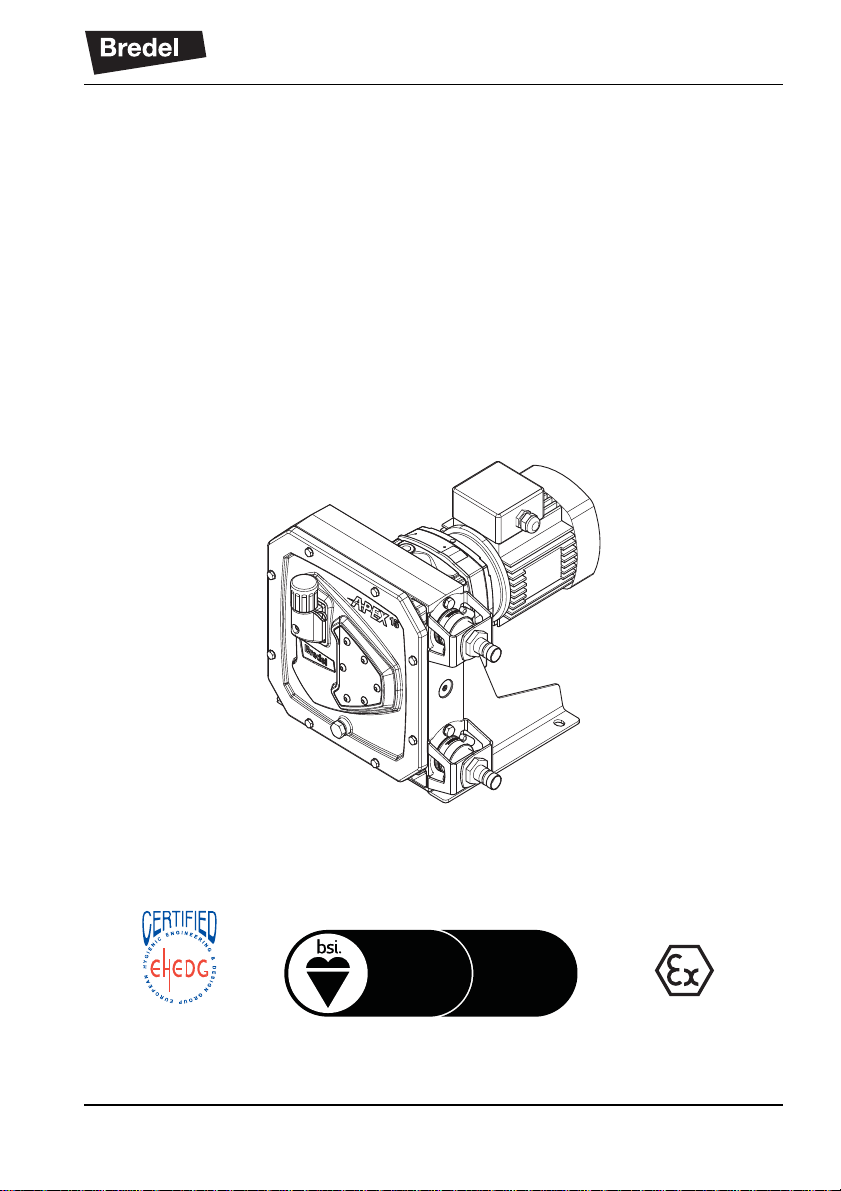
Hose pump series
TYPE EL - CLASS I
AUGUST 2012
Environmental
Management
ISO
14001
Quality
Management
ISO
9001
APEX10, APEX15 and APEX20
Manual
3
Page 4

© 2014 Watson-Marlow Bredel B.V.
All rights reserved.
The information provided herein may not be reproduced and/or published in any form,
by print, photoprint, microfilm or any other means whatsoever (electronically or
mechanically) without the prior written authorisation of Watson-Marlow Bredel B.V.
The information provided can be changed without prior notification. Watson-Marlow
Bredel B.V. or one of its representatives cannot be held liable for possible damage
resulting from use of this manual. This is an extensive limitation of the liability which
applies to all damage, inclusive of (without limitation) compensating, direct, indire ct or
consequential damage, loss of data, income or profit, loss or damage to possessions
and claims of third parties.
Watson-Marlow Bredel B.V. provides the information in this manual "as is" and does not
take any responsibility and does not give any guarantee on this manual o r its content.
Watson-Marlow Bredel B.V. rejects all responsibilities and guarantees. Furthermore,
Watson-Marlow Bredel B.V. does not take responsibility for and does not guarantee that
the information in this manual is accurate, complete or up to date.
Names, trade names, brands, etc. used by Watson-Marlow Bredel B.V. may not, as per
the legislation concerning the protection of trade names, be considered as available.
4
Page 5

CONTENTS
1GENERAL
1.1 How to use this manual .................................. ........................................ 8
1.2 Original instructions ................................................................................ 8
1.3 Other supplied documentation ................................................................ 8
1.4 Service and support .................................................................... ... ... ...... 8
1.5 Environment and disposal of waste ........................................................ 9
2SAFETY
2.1 Symbols ................................................................................................ 10
2.2 Intended use ......................................................................................... 10
2.3 Use in potentially explosive atmospheres ............................................. 11
2.4 EHEDG compliance .............................................................................. 11
2.5 Responsibility ........................................................................................ 12
2.6 Qualification of the user ........................................................................ 12
2.7 Regulations and instructions ................................................................. 12
3 WARRANTY CONDITIONS
4 DESCRIPTION
4.1 Identification of the product ................................................................... 14
4.1.1 Identification of the product ....................................................... 14
4.1.2 Identification of the pump .......................................................... 14
4.1.3 Identification of the gearbox ...................................................... 14
4.1.4 Identification of the electric motor .............................................. 15
4.1.5 Identification of the frequency controller .................................... 15
4.1.6 Identification of the pump hose ................................................. 15
4.2 Construction of the pump ...................................................................... 16
4.3 Operation of the pump .......................................................................... 17
4.4 Pump hose ...................................... .. ..................................... ... ............ 18
4.4.1 General ...................................................................................... 18
4.4.2 Hose compression force adjustment ......................................... 19
4.4.3 Lubrication and cooling ............................................................. 19
4.5 Gearbox ................................................................................................ 20
4.6 Electric motor ........................................................................................ 20
4.7 Available options ................................................................................... 20
5
Page 6

5 INSTALLATION
5.1 Unpacking ............................................................................................ 21
5.2 Inspection ............................................................................................. 21
5.3 Installation conditions ........................................................................... 21
5.3.1 Ambient conditions .................................................................... 21
5.3.2 Setup ......................................................................................... 21
5.3.3 Pipework ................................................................................... 22
5.3.4 Motor ......................................................................................... 23
5.3.5 Frequency controller ................................................................. 23
5.4 Lifting and moving the pump ................................................................ 24
5.5 Placing the pump .................................................................................. 24
6 COMMISSIONING
6.1 Preparations ......................................................................................... 25
6.2 Commissioning ..................................................................................... 26
7 OPERATION
7.1 Temperature ......................................................................................... 27
7.2 Power rating ................................................. ... ... .................................. 27
7.3 Performance graphs ........................................ ..................................... 28
7.4 Dry running ........................................................................................... 30
7.5 Hose failure ...................................................................................... ... . 31
7.6 Fluid leakage ........................................................................................ 33
8 MAINTENANCE
8.1 General ................................................................................................. 34
8.2 Maintenance and periodic inspections ................................................. 34
8.3 Cleaning the pump hose ...................................................................... 36
8.4 Changing lubricant ............................................................................... 36
8.5 Replacing the pump hose ..................................................................... 37
8.5.1 Removing the pump hose ......................................................... 37
8.5.2 Cleaning the pumphead ............................................................ 38
8.5.3 Fitting the pump hose ................................................................ 39
8.6 Exchanging replacement parts ............................................................. 41
8.6.1 Replacing rotor, bearings and seal ring .................................... 41
8.7 Fitting options ....................................................................................... 44
8.7.1 Fitting a high-level float switch .................................................. 44
8.7.2 Replacing the revolution counter ............................................... 46
6
Page 7

9 STORAGE
9.1 Hose pump ........................................................................................... 48
9.2 Pump hose ...................................... .. ..................................... ... ............ 48
10 TROUBLESHOOTING
11 SPECIFICATIONS
11.1 Pumphead ............................................................................................ 54
11.1.1 Performance .............................................................................. 54
11.1.2 Materials .................................................................................... 55
11.1.3 Surface treatment ...................................................................... 56
11.1.4 Lubricant table pump ................................................................. 56
11.1.5 Weights ..................................................................................... 57
11.1.6 Torque figures ........................................................................... 58
11.2 Gearbox ................................................................................................ 59
11.3 Electric motor ........................................................................................ 59
11.4 Variable Frequency Drive (VFD) (optional) ........................................... 60
11.5 Parts list ................................................................................................ 60
11.5.1 Ordering parts .................................................................... ... ... . 60
11.5.2 Overview ................................................................................... 61
11.5.3 Cover assembly ......................................................................... 62
11.5.4 Pumphead assembly ................................................................. 63
11.5.5 Support assembly ...................................................................... 64
11.5.6 Barbed nipple assembly (PTFE/PDVF) ..................................... 65
11.5.7 Barbed or threaded nipple assembly
(stainless steel/PP/PVC) ........................................................... 66
11.5.8 Flange assembly with insert with collar ..................................... 67
11.5.9 Flange assembly with threaded nipple ...................................... 68
11.5.10Lubricant ................................................................................... 68
EC DECLARATION OF CONFORMITY OF THE MACHINERY
SAFETY FORM
NOTES
7
Page 8

GENERAL
1GENERAL
1.1 How to use this manual
This manual is intended as a reference book by means
of which qualified users are able to install, commission
and maintain the hose pumps mentioned on the front
cover.
1.2 Original instructions
The original instructions for this manual have been
written in English. Other language versions of this
manual are a translation of the original instructions.
1.3 Other supplied documentation
Documentation of components such as the gearbox, the
motor and the frequency controller is not included in this
manual. However, if additional documentation is
supplied, you must follow the instructions in this
additional documentation.
1.4 Service and support
For information with respect to specific adjustments,
installation, maintenance or repair jobs which fall
beyond the scope of this manual, contact your Bredel
representative. Make sure you have the following data
at hand:
• Serial number of the hose pump
• Article number of the pump hose
• Article number of the gearbox
• Article number of the electric motor
• Article number of the frequency controller
You will find these data on the identification plates or
stickers on the pumphead, the pump hose, the gearbox
and the electric motor. Refer to § 4.1.1.
8
Page 9

1.5 Environment and disposal of waste
CAUTION
Always observe the local rules and
regulations with respect to processing (non
reusable) parts of the hose pump.
Enquire within your local government about the
possibilities for reuse or environment-friendly
processing of packaging materials, (contaminated)
lubricant and oil.
GENERAL
9
Page 10
SAFETY
2SAFETY
2.1 Symbols
In this manual the following symbols are used:
WARNING
Procedures which, if not carried out with
the necessary care, may result in serious
bodily harm.
CAUTION
Procedures which, if not carried out with
the necessary care, may result in serious
damage to the hose pump, the surrounding
area or the environment.
Remarks, suggestions and advice.
2.2 Intended use
The hose pump is exclusively designed for pumping
suitable products. Every other or further use is not in
conformance with the intended use.
Flammable fluids are not suitable products to be
pumped by this hose pump. This pump is not intended
to operate in potentially explosive atmospheres.
The "Intended use" as laid down in EN 292-1 is "... the
use for which the technical product is intended in
accordance with the specifications of the manufacturer,
inclusive of his indications in the sales brochure". In
case of doubt it is the use, which appears to be its
intended use judging from the construction, execution
and function of the product, and its description in the
user's documentation.
Only use the pump in conformance with the intended
use described above. The manufacturer cannot be h eld
responsible for damage or harm resulting from use that
10
Page 11

is not in conformance with the intended use. If you want
to change the application of your hose pump, contact
your Bredel representative first.
2.3 Use in potentially explosive atmospheres
The pumphead and drive mentioned in this manual may
be configured to be suitable for use in a potentially
explosive atmosphere. Such a pump meets the
requirements as stated in the European Directive 94/9/
EC (ATEX Directive). Such a pump belongs to: Group II
appliances, category 2 GD bck T5.
Use in potentially explosive atmospheres
requires special configuration of the pump
unit. Contact your Bredel representative for
use in explosive atmospheres.
See Bredel’s ATEX Instruction manual which is supplied
with pumps configured as mentioned above.
2.4 EHEDG compliance
SAFETY
The hose connections of the pumphead described in
this manual are EHEDG compliant when stainless steel
nipples are applied and the connections are properly
created. This only concerns the connection between
nipple and pump hose.
WARNING
The user is responsible for the EHEDG
compliance of the connection between
nipple and suction or discharge line if
compliance is needed.
See the user guide “NBR Hoses For Food Contact”
supplied with F-NBR hoses for a description of a proper
hose connection.
11
Page 12

SAFETY
2.5 Responsibility
The manufacturer does not accept any responsibility for
damage or harm caused by not observing the safety
regulations and instructions in this manual and other
supplied documentation, or by negligence during
installation, use, maintenance and repair of the hose
pumps mentioned on the front cover. Depending on the
specific working conditions or accessories used,
additional safety instructions can be required.
Immediately contact your Bredel representative if you
notice a potential danger while using your hose pump.
WARNING
The user of the hose pump is fully
responsible for observing local safety
regulations and directives. Observe these
safety regulations and directives when
using the hose pump.
2.6 Qualification of the user
The installation, use and maintenance of the hose
pump should only be performed by well-trained and
qualified users. Temporary staff and persons in training
may use the hose pump only under the supervision and
responsibility of trained and qualified users.
2.7 Regulations and instructions
• Everyone who works with the hose pump must
be aware of the contents of this manual and
observe the instructions with great care.
• Never change the order of the actions to be
carried out.
• Always store the manual near the hose pump.
12
Page 13

3 WARRANTY CONDITIONS
The manufacturer offers a two-year warranty on all
parts of the hose pump. This means that all parts will be
repaired or replaced free of charge, with the exception
of consumables such as pump hoses, hose clamps, ball
bearings, wear rings, seals and rubber bushes, or parts
which have been used wrongly, misused, whether or
not they have been intentionally damaged. If genuine
Watson-Marlow Bredel B.V. (hereafter called Bredel)
parts are not used, any warranty claim is void.
Damaged parts which are covered by the applicable
warranty conditions can be returned to the
manufacturer. The parts must be accompanied by a
fully filled in and signed safety form, as present in the
back of this manual. The safety form must be applied to
the outside of the shipping carton. Parts which have
been contaminated or which have been corroded by
chemicals or other substances which can pose a health
risk must be cleaned before they are returned to the
manufacturer. Furthermore, it should be indicated on
the safety form which specific cleaning procedure has
been followed, and that the equipment has been
decontaminated. The safety form is required even if the
parts have not been used.
WARRANTY CONDITIONS
Warranties purporting to be on behalf of Bredel made
by any person, including representatives of Bredel, its
subsidiaries, or its distributors, which do not accord with
the terms of this warranty shall not be binding upon
Bredel unless expressly approved in writing by a
Director or Manager of Bredel.
13
Page 14
DESCRIPTION
min-1
N
o
i
D A
B
E
C
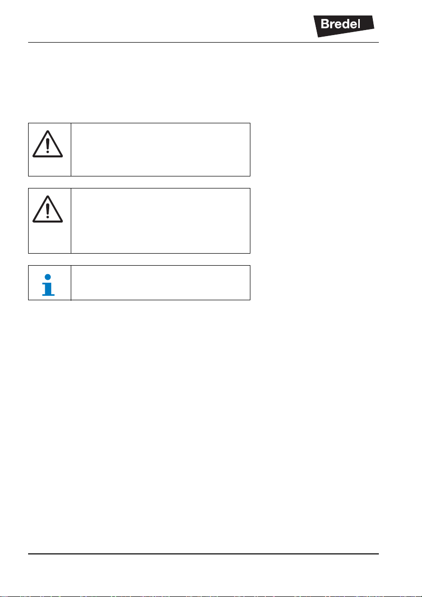
4 DESCRIPTION
4.1 Identification of the product
4.1.1 Identification of the product
The hose pump can be identified by identification plates
or stickers on:
A Pumphead
B Gearbox
C Electric motor
D Pump hose
E Frequency controller (option)
E
C
B
4.1.2 Identificati on of the pump
The identification plate on the pumphead contains the
following data:
A Pump type, hose diameter and rotor type (low
or medium pressure)
B Serial number
C Year of manufacture
4.1.3 Identification of the gearbox
The identification plate on the gearbox contains the
following data:
A Article number
B Serial number
C Type number
D Reduction ratio
E Number of revolutions per minute
A
A C
APEX
Serial No:.
YEAR:
Watson-Marlow Bredel B.V.
Sluisstraat 7-Delden-NL
www.bredel.com
B
10 15 20
LOW
D
MED.
14
Page 15
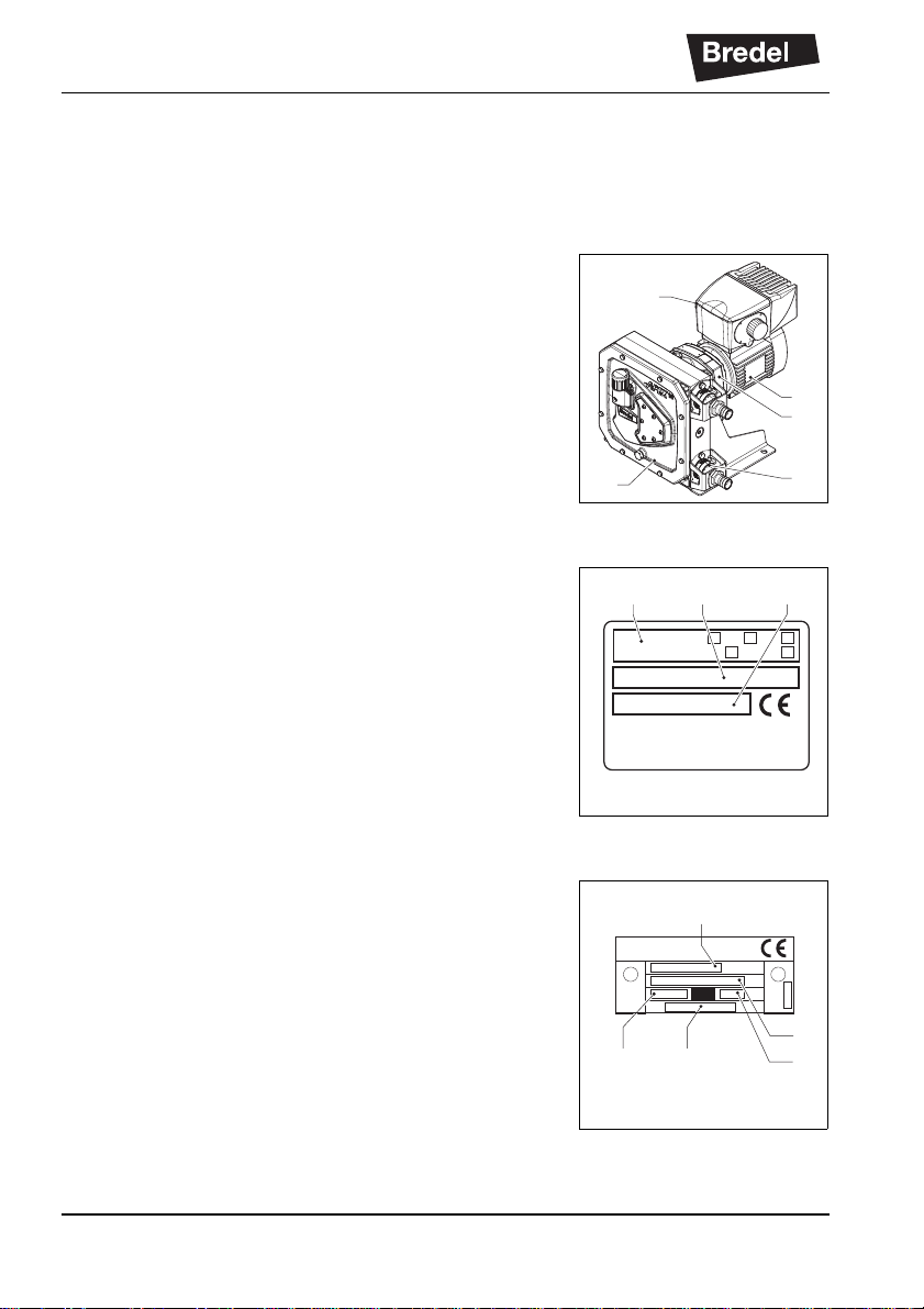
4.1.4 Identification of the electric motor
V
S
IP IK
Hz min-1 kW A
COS
C/h%
N
o
U
N
V
P
Mf
Nm
CF
o
D E F
GH I
C
B
The identification plate on the electric motor contains
the following data:
B Serial number
C Article number
D Mains
E Frequency
F Speed
G Power
H Power factor
I Current
4.1.5 Identification of the frequency controller
The identification of the Bredel Variable Frequency
Drive (VFD) can be found inside the VFD. Remove the
cover by loosening the two screws. The identification
sticker contains the following data:
A Article number
B Serial number
DESCRIPTION
B
LS serial number
sn20837003969
Bredel article number E384083
A
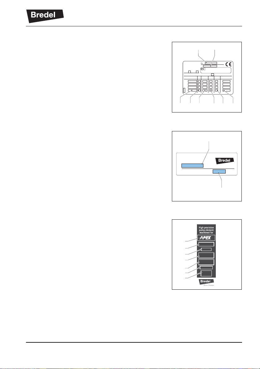
4.1.6 Identif ication of the pump hose
The identification sticker on the pump hose contains the
following data:
A: Pump type
B: Part code
C: Internal diameter
D: Type of material of inner liner
E: Remarks, if applicable
F: Maximum permissible working pressure
G: Production code
A
B
C
D
E
F
G
15
Page 16
DESCRIPTION
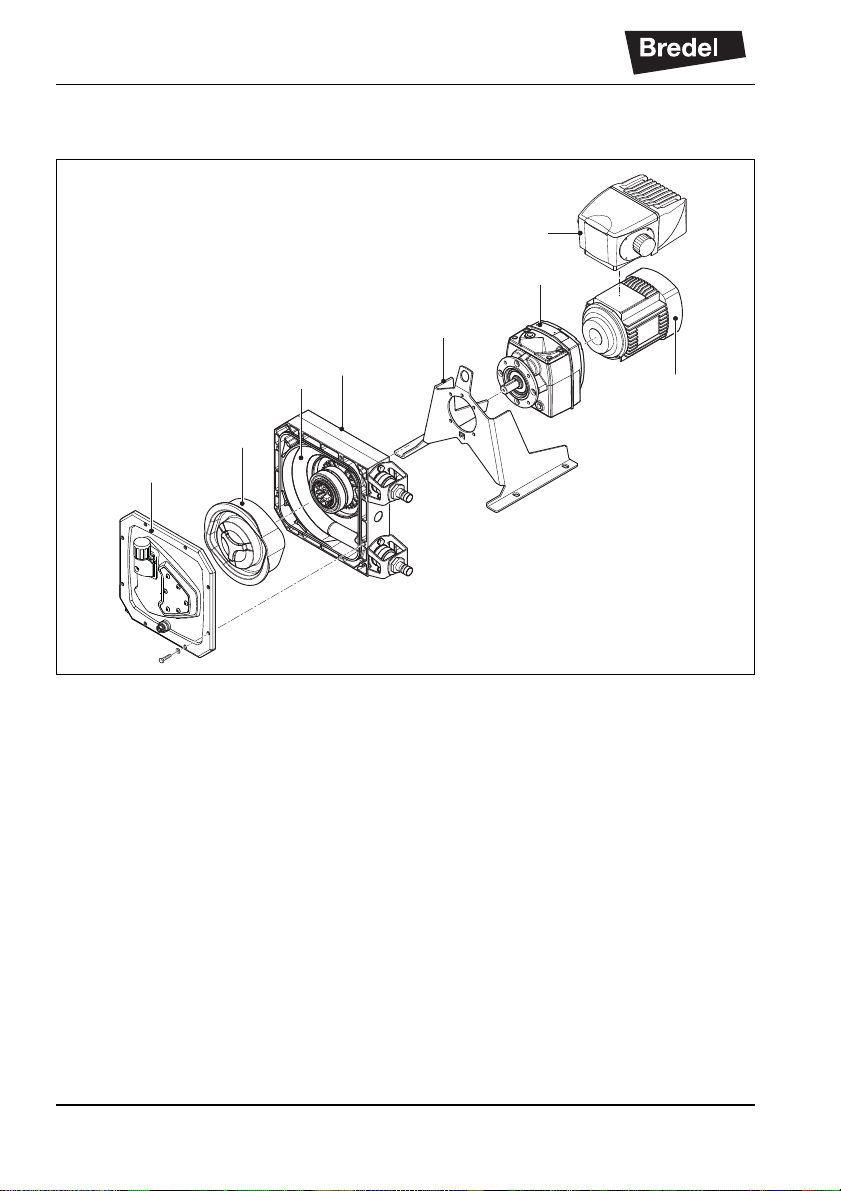
4.2 Construction of the pump
C
B
A
H
F
E
D
G
A Cover
B Rotor
C Pump hose
D Pump housing
E Support
F Gearbox
G Electric motor
H Frequency controller
16
Page 17
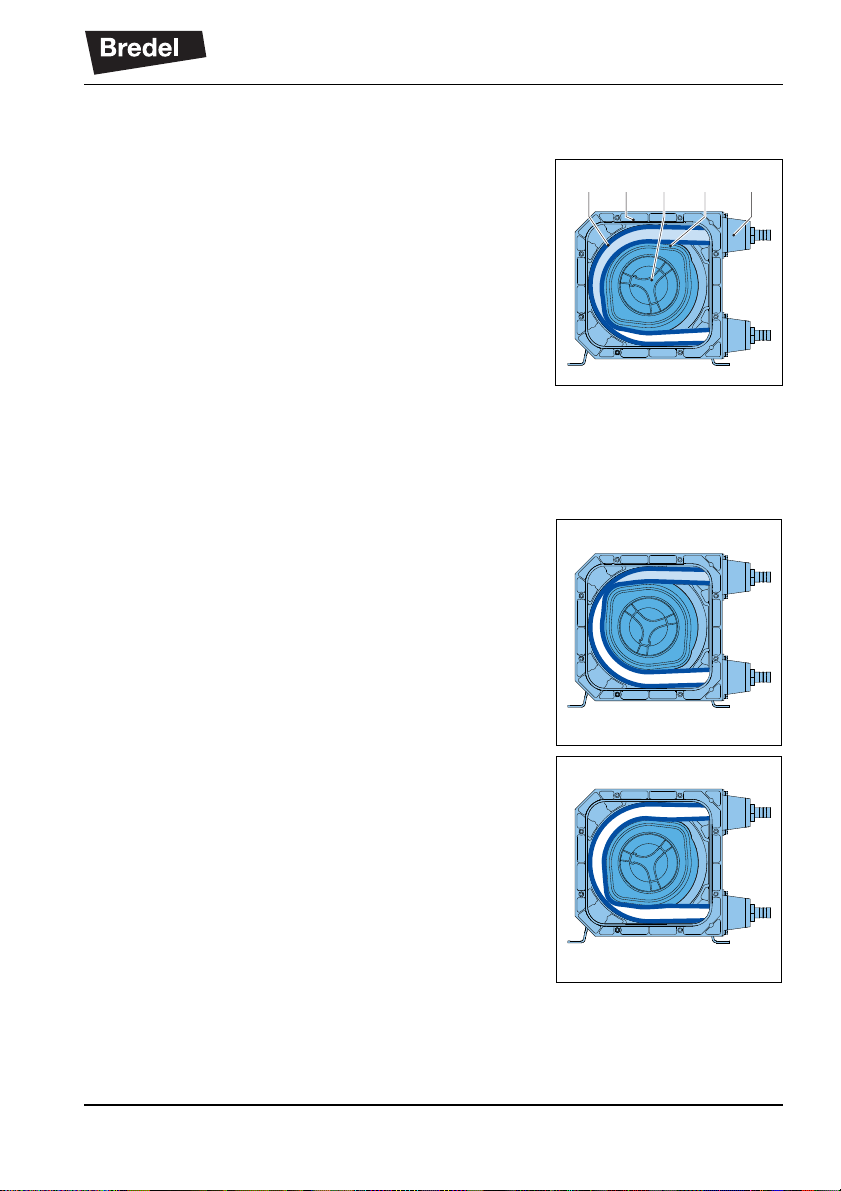
4.3 Operation of the pump
The heart of the pumphead consists of a specially
constructed pump hose (A) which lies against the inside
of the pump housing (B). The ends of the hose are
connected to the suction and discharge lines (C). A
bearing-mounted rotor (D) with two facing integral
pressing shoes (E) is in the centre of the pumphead. It
rotates clockwise.
In phase 1 the lower shoe compresses the pump hose
by the rotational movement of the rotor, forcing fluid
through the hose. As soon as the shoe has passed, the
hose recovers to its original shape due to the
mechanical properties of the material and fluid is drawn
into the hose.
In phase 2 fluid is drawn through the hose by the
(continuous) turning motion of the rotor.
DESCRIPTION
AB E CD
In phase 3, the second integral pressing shoe
compresses the pump hose. Due to the continuous
rotating movement of the rotor new fluid is sucked in
and fluid that is previously drawn in is pressed out by
the shoe. When the first shoe leaves the pu mp hose,
the second shoe has already occluded the pump hose
and fluid is prevented from flowing back. This method of
liquid displacement is known as the "positive
displacement principle".
17
Page 18
DESCRIPTION
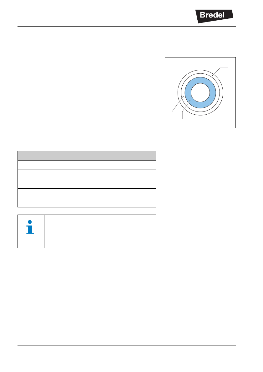
4.4 Pump hose
4.4.1 General A Extruded outer layer made of natural rubber B Two nylon reinforcement layers C Extruded inner liner
The pump hose liner material should be chemically
resistant to the product being pumped. For each pump
model various hose types are available. Choose the
most appropriate for your application.
The material of the inner liner of the pump hose
determines the hose type. Each hos e ty pe i s marked by
a unique colour code.
Hose type Material Colour code
NR Natural rubber Purple
NBR Nitrile rubber Yellow
F-NBR Nitrile rubber Yellow
EPDM EPDM Red
CSM CSM Blue
A
B C
Consult your Bredel representative for
more detailed information about the
chemical and temperature resistance of
pump hoses.
Bredel pump hoses have been carefully machined to
achieve minimum tolerances in wall thickness. It is very
important to guarantee the correct compression of the
pump hose, because:
• When the compression is too high, it creates an
excessive load on the pump and pump hose,
which may reduce the life of the pump hose and
bearings.
• When the compression is too low, it cuts
capacity and causes backflow. Backflow
reduces the life of the pump hose.
18
Page 19
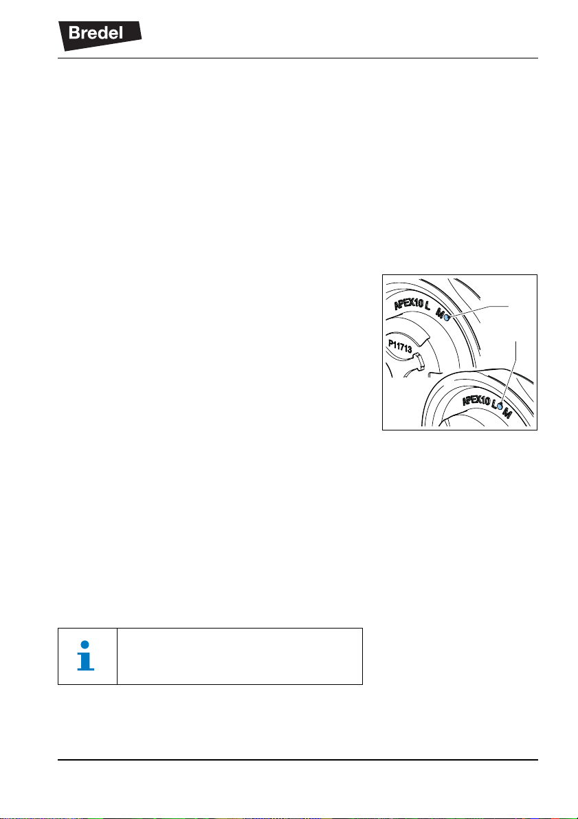
4.4.2 Hose compress ion force adjustment
The compression force on the pump hose can be
adjusted by installing a rotor with a different dimension
between the tips of the integral pressing shoes. The
rotor is chosen to achieve an optimal life of the pump
hose for the intended use of the hose pump. Each hose
size (10, 15 or 20 mm inner diameter) has its own lowpressure and medium-pressure rotors. This means
there are six types of rotors available. If you want to
change the application of your hose pump or if you want
to change the hose size, contact your Bredel
representative.
Low-pressure and medium-pressure rotors can be
recognized by a marked hole near the “L” for “Lowpressure” (B) or near the “M” for “Medium-pressure” (A)
on the rotor.
DESCRIPTION
A
B
4.4.3 Lubrication and cooling
The pumphead is filled with Bredel Genuine Hose
Lubricant. This lubricant lubricates the shoes and
dissipates the heat generated by the movement of the
pressing shoes against the pump hose.
The lubricant is food grade. The user is responsible to
ensure the chemical compatibility of the lubricant with
the fluid to be pumped. Refer to § 11.1.4 for the
required quantity and NSF registration.
Refer to § 7.5 for the consequences of a hose failure.
Consult your Bredel representative for
lubrication recommendations when
operating the hose pump below 2 rpm.
19
Page 20

DESCRIPTION
4.5 Gearbox
The hose pump types described in this manual use
helical gearbox units. Other gearbox types are available
as option. The gearboxes are fitted with a flange
connection. Refer to § 11.2 for specifications. Refer to
the documentation supplied with the gearbox for
installation and maintenance information. In case of
doubt, consult your Bredel representative.
4.6 Electric motor
The standard electric motor is a completely enclosed
three-phase asynchronous motor. The motor
connection must meet the local applicable regulations.
Refer to the documentation supplied with the electric
motor for installation and maintenance information. In
case of doubt consult your Bredel representative. Refer
to § 5.3.4 and § 6.1 for installation and connection
information.
4.7 Available options
The following options are available for the hose pump:
• High (lubricant) level float switch
• Revolution counter
• Medium- or low-pressure rotor (depending on
the discharge pressure)
• Frequency controller
1
• Three hose sizes
• Five hose types
• Various types of hose connection
• Worm gear drive
• Special configuration for use in explosive
atmospheres
1 Refer to the supplier’s documentation and § 11.4.
20
Page 21

5INSTALLATION
5.1 Unpacking
Follow the unpacking instructions on the packaging or
on the hose pump, the gearbox and the electric motor.
5.2 Inspection
Check that your delivery is correct and check it for any
transport damage. When replacing parts, check that the
delivery is correct and check these parts for any
transport damage. Refer to § 4.1.1. Report any damage
immediately to your Bredel representative.
5.3 Installation conditions
5.3.1 Ambient conditions
Make sure that the hose pump is in an area where the
ambient temperature during operation is not lower than
-20 °C and not higher than +45 °C.
INSTALLATION
5.3.2 Setup
• The pump materials and protective layers are
suitable for indoor setup and a protected
outdoor setup. Under certain conditions the
pump is suitable for limited outdoor setup or a
salty or aggressive atmosphere. Consult your
Bredel representative for more information.
• Make sure that the floor surface has a
maximum slope of 10 mm per metre.
• Make sure that there is sufficient room around
the pump to carry out the necessary
maintenance.
• Make sure that the room is sufficiently
ventilated, so that the heat developed by the
pump and drive can be dissipated. Keep some
distance between the ventilation cover of the
electric motor and the wall to allow the supply of
cooling air.
21
Page 22
INSTALLATION
5.3.3 Pipework
When determining and connecting suction and
discharge lines consider the following points:
• It is recommended that the bore size of the
suction and discharge lines is larger than the
bore size of the pump hose. For more
information consult your Bredel representative.
• Limit the presence of sharp bends in the
discharge line. Make sure that the radius of any
bend is as large as possible. Use Y-connections
instead of T-connections.
• It is recommended to use a minimum of three
quarters (3/4) of the hose length as flexible
hose in the suction or discharge line. This
avoids the need to remove the connection l ines
when changing a pump hose.
• Keep the delivery and suction lines as short and
direct as possible.
• Select the correct mounting material for flexible
hoses and make sure that the installation is
suited for the design pressure of the system.
• Do not exceed the maximum working pressure
of the hose pump. Refer to § 11.1.1. If
necessary fit a pressure relief valve.
CAUTION
Consider the maximum permissible
working pressure on the discharge side.
Exceeding the maximum working pressure
may lead to serious damage to the pump.
• Make sure that the maximum forces on the
flanges are not exceeded. The permissible
loads are given in the following table.
22
Page 23

Maximum permissible loads [N] on the
pump connections
Force APEX10, 15, 20
F1 600
F2 120
F3 300
5.3.4 Motor
The motor connection must meet the local applicable
regulations. A thermal safety device should reduce the
risk of a motor overload. For connecting PTC
thermistors (if present) a special thermistor relay must
be used. In case of doubt, contact your Bredel
representative for advice. Refer to § 11.3 for
specifications.
Refer to the documentation supplied with the electric
motor for information on how to connect the motor to
your power supply.
INSTALLATION
F2
F1
F3
5.3.5 Frequency controller
WARNING
A frequency controller that is fitted without
manual control can start the pump
automatically when power is applied.
If the hose pump is fitted with a frequency controller,
consider the following points:
• Take precautions so the motor does not restart
automatically after an unscheduled stop.
In the event of a power or mechanical failure,
the frequency controller stops the motor. When
the cause of the failure is removed, the motor
can restart automatically. The automatic restart
can be dangerous in certain pump installations.
23
Page 24

INSTALLATION
• All control cables outside the enclosure must be
shielded and have a cross sectional area
between 0.22 mm
must be connected to earth at both ends. In
case of doubt, consult your Bredel
representative.
5.4 Lifting and moving the pump
The pump support has a lifting eye (A) for lifting and
moving the hose pump.
The complete hose pump, i.e. pumphead, gearbox and
electric motor, must be lifted using the lifting eye plus
additional support using suitably rated straps or
slings (A). For the weights, refer to § 11.1.5.
2
and 1 mm2. The shielding
A
A
WARNING
If the pump is to be lifted ensure that all
standard lifting practices are adhered to
and carried out by qualified personnel only.
5.5 Placing the pump
Position the pump on a horizontal surface. Use suitable
anchor bolts to attach the pump to the floor surface.
24
Page 25

6 COMMISSIONING
6.1 Preparations
WARNING
A frequency controller that is fitted without
manual control can start the pump
automatically when power is applied.
WARNING
Disconnect and lock the power supply to
the pump drive before any work is carried
out.
In case the motor is fitted with a frequency
controller and has a single-phase power
supply, wait two minutes to make sure that
the capacitors have discharged.
1. Connect the electric motor and, if present, the
frequency controller in conformance with the
locally applicable rules and regulations. Refer to
§ 5.3.4 and § 5.3.5. Have the electrical
installation work carried out by qualified
personnel.
COMMISSIONING
2. Check that the lubricant level is above the
minimum level line in the inspection window. If
necessary refill with Bredel Genuine Hose
Lubricant via the breather plug. Also refer to
§ 8.4.
25
Page 26

COMMISSIONING
6.2 Commissioning
1. Connect the pipework.
2. Make sure that there are no obstructions such
as closed valves.
3. Switch on the hose pump.
4. Check the rotation of the rotor.
5. Check the capacity of the hose pump. If the
capacity differs from your specification, follow
the instructions in chapter 10 or consult your
Bredel representative.
6. If a frequency controller is present, check the
capacity range. In case of any deviations
consult the supplier’s documentation.
7. Check the hose pump in accordance with points
2 to 4 of the maintenance table at § 8.2.
26
Page 27

7 OPERATION
7.1 Temperature
The pump will heat up during normal operation. Heat is
generated in the contact zone between the pressing
shoe and the hose. The heat is removed by the
lubricant and transported to the pump casing and cover.
This will result in a temperature higher than the ambient
temperature.
WARNING
Avoid contact with the casing and cover
under conditions of high pressure and
running speed.
7.2 Power rating
The pump requires a certain amount of power for the
specified operating condition(s). The gearbox and
motor should be capable of handling that power at the
given revolution speeds. Refer to § 7.3 to determine the
required power.
OPERATION
WARNING
Overloading the motor can lead to serious
motor damage. Do not exceed the
maximum power rating of the motor.
WARNING
Overloading the gearbox leads to
increased tooth wear and shortened
bearing life. This can lead to serious
gearbox damage. Do not exceed the
maximum power rating of the gearbox.
27
Page 28

OPERATION
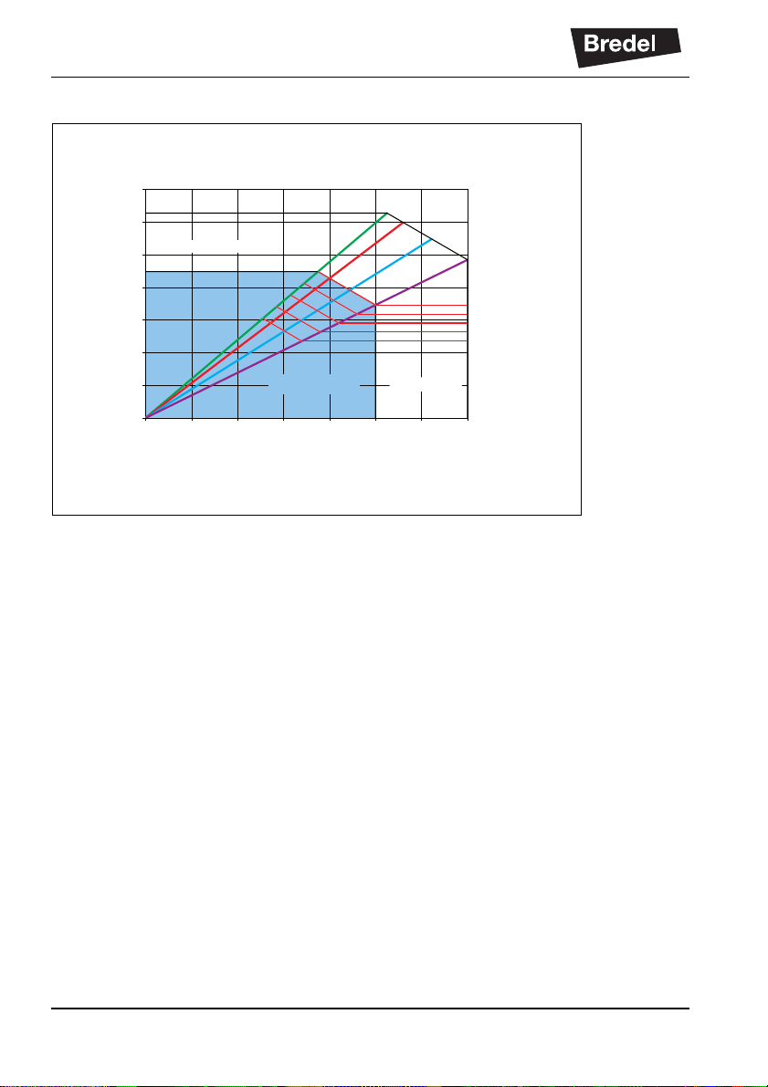
7.3 Performance graphs
Useful operating duties can be found in the
performance graphs in which discharge-pressure
curves are displayed in a speed-power diagram.
Even at 0 kPa discharge pressure a certain torque is
required to let the pump rotor rotate. The pump and
hose are designed to handle a discharge pressure up to
800 kPa. The triangular area between the 0 kPa and the
800 kPa lines describes the allowed performance area.
The required duty points have to fall within this area.
In the direction of higher speeds and powers, pump
operation is limited by the heat generated, the product
temperature and the ambient temperature. Producttemperature lines determine a distinction between
areas of continuous operation and intermittent
operation in the graphs. The graphs apply for a
maximum ambient temperature of 40 °C.
If the duty for an application is specified in the area of
intermittent operation, let the pump stand still to cool
down for at least one hour after three hours of
operation.
28
Page 29

7.3.1 Performance graph APEX10:
0.00
02040
40
50
60
70
80
60 80 100 120 140
0 55 110 165 220 275 330 385
0.05
0.10
0.15
0.20
0.25
0.30
0.35
0.40
0.45
0.50
Pump Speed [rpm]
Capacity [L/h]
Required Motor Power [kW]
0 kPa
300 kPa
600 kPa
800 kPa
Intermittent Duty
Continuous Duty
100 kPa =1 bar
Product
temperature
(°C)
0.00
0 20 40 60 80 100 120 140
0 110 220 330 440 550 660 770
0.10
0.20
0.30
0.40
0.50
0.60
Pump Speed [rpm]
Capacity [L/h]
Required Motor Power [kW]
0 kPa
300 kPa
600 kPa
800 kPa
Intermittent Duty
Product
temperature
(°C)
40
50
60
70
80
Continuous Duty
100 kPa =1 bar
7.3.2 Performance graph APEX15:
OPERATION
29
Page 30
OPERATION
0,00
0,10
0,20
0,30
0,40
0,50
0,60
0,70
02040
40
50
60
70
80
60 80 100 120 140
0 175 350 525 700 875 1050 1225
Pump Speed [rpm]
Capacity [L/h]
Required Motor Power [kW]
0 kPa
300 kPa
600 kPa
800 kPa
Intermittent Duty
Continuous Duty
100 kPa =1 bar
Product
temperature
(°C)
7.3.3 Performance graph APEX20:
7.4 Dry running
Dry running is a running condition of the pump when no
fluid is flowing through the pump. Bredel peristaltic
pumps are very suitable for dry run nin g.
Dry running imposes an additional thermal load on the
pump hose, because a part of the internal heat
associated with repetitive hose compression is normally
removed by the process fluid. So dry running increases
the wear on the hose. The thermal load depends on the
running speed of the pump, the hose size (10, 15, 20
mm) as well as the rotor type (low pressure or medium
pressure). To minimise the extra wear, it is advisable to
minimise dry running periods.
30
Page 31

7.5 Hose failure
Cause of a hose failure
The hose in a peristaltic pump has to withstand many
load cycles of considerable magnitude. The repetitive
stress cycles will cause the hose to deteriorate and
eventually fail.
Result of a hose failure
A hose failure will result in direct contact between the
pump lubricant and the pumped fluid.
Consequences of a hose failure
In general, this will not cause a hazardous situation
because the Bredel Genuine Hose Lubricant is
harmless (approved by the United States Food and
Drug Administration). However, there is an exception in
case of pumping a strong oxidiser or a strong acid.
Refer to § 11.1.4 about chemical compatibility.
OPERATION
31
Page 32

OPERATION
• Hazardous situations
WARNING
Avoid direct contact between a strong
oxidiser or a strong acid and Bredel
Genuine Hose Lubricant. This can cause
unwanted chemical reactions. Use an
alternative lubricant to avoid hazardous
situations. Contact your Bredel
representative for more details.
• Additional downtime
Hose failure will result in additional downtime,
because you must clean the pump before a new
hose installation.
Regularly replace the hose to avoid hose
failure and additional downtime. Hose life
depends on the operating condition,
process fluid and hose material. The enduser should be aware of this and establish
the frequency of preventive hose
replacement. Contact your Bredel
representative for advice.
• Large spill of product
In case the pressure in the process line
(reservoir) is above the pressure in the pump
housing (ambient pressure), the process fluid
can enter the pump housing. If there is no check
valve in the process line a serious amount of
fluid can flow from the reservoir into the pump
housing and escape through the breather onto
the floor. This could lead to a large spill of
product outside the pump. Reversed flow
protection is advised. This is not part of the
scope of delivery.
32
Page 33

7.6 Fluid leakage
The APEX pump uses a lubricated rotor to compress
the hose. This means the pumphead must be filled with
sufficient lubricant during operation. This lubricant is
contained in the pump housing by the front cover and
by a dynamic seal on the back. The gearbox is filled
with gearbox lubricant.
Seal damage can occur due to normal wear in time, but
is seriously accelerated if the seal gets in contact with
contaminated lubricant. Thorough cleaning of the pump
housing after a hose failure and regular replacement of
the lubricant is strongly advised.
The pumphead and gearbox are directly coupled to
each other. A special feature is included in the
pumphead to allow early detection of seal damage of
the pump or gearbox.
This feature is called the leakage zone. Drops of
lubricant visible at the back of the pump indicate likely
seal failure. To avoid consequential damage, the pump
must be stopped and lubricant levels of the pumphead
and gearbox must be checked. The damaged seal
should be replaced.
OPERATION
Regularly inspect the pump for fluid
leakage.
WARNING
Risk of injury from falling! Process fluid
mixed with pump lubricant that is leaking
from the pump can make floors slippery.
33
Page 34

MAINTENANCE
8 MAINTENANCE
8.1 General
WARNING
Disconnect and lock the power supply to
the pump drive before any work is carried
out.
In case the motor is fitted with a frequency
controller and has a single-phase power
supply, wait two minutes to make sure that
the capacitors have discharged.
WARNING
Do not remove the pump cover if the power
cable is connected to the motor. Do not
connect the power cable to the motor if the
pump cover is removed.
Only use original Bredel parts when maintaining the
hose pump. Bredel cannot guarantee correct operation
and any consequential damage that occurs from the
use of non-original Bredel components. Also refer to
chapters 2 and 3.
Check that your delivery of original parts is correct and
check it for any transport damage. If parts are
damaged, consult your Bredel representative.
Before installation, always check the
condition of the supplied parts. Do not
install damaged parts. In case of doubt,
contact your Bredel representative.
8.2 Maintenance and periodic inspections
The following diagram shows the maintenance and
periodic inspection that need to be carried out on the
hose pump to guarantee optimal safety, operation and
life of the pump.
34
Page 35

MAINTENANCE
Point Action To be carried out Remark
1 Checking the lubricant
level.
2 Checking the pump-
head for any leakage of
lubricant around the
cover, the brackets and
the rear of the pumphead.
3 Checking the gearbox
for any leakage.
4 Checking the pump for
deviating temperature or
strange noises.
5 Checking the rotor with
integral pressing shoes
for excessive wear.
6 Internal cleaning of the
pump hose.
7 Replacing the pump
hose.
8 Changing lubricant. After every second hose
9 Replacing the seal ring. If necessary. Refer to § 8.6.1.
Before starting the pump
and at scheduled intervals during operation.
Before starting the pump
and at scheduled intervals during operation.
Before starting the pump
and at scheduled intervals during operation.
At scheduled intervals
during operation.
When replacing the
pump hose.
Cleaning of the system
or fluid change.
Preventive, this means
after 75% of the hose life
of the first hose.
change or after 5,000
service hours, whichever
comes first, or after hose
rupture.
Make sure that the lubricant level is above the
minimum level line in the
inspection window.
If necessary refill the
lubricant. Also refer to
§ 8.4.
Refer to § 10.
In case of leakage consult your Bredel representative.
Refer to § 10.
Refer to § 8.5.
Refer to § 8.3.
Refer to § 8.5.
Refer to § 8.4
35
Page 36

MAINTENANCE
Point Action To be carried out Remark
10 Replacing the rotor with
integral pressing shoes.
Wear on the running surface of the pump hose
and/or seal ring.
11 Replacing the bearings. If necessary. Refer to § 8.6.1.
8.3 Cleaning the pump hose
The inside of the pump hose can be easily cleaned by
rinsing the pump with clean water. If a cleaning fluid is
added to the water, check if the hose liner material is
resistant to it. Also check if the pump hose can resist
the cleaning temperature. Special cleaning balls are
also available. Contact your Bredel representative for
more details.
8.4 Changing lubricant
1. Place a tray (A) under the drain plug, which is in
the cover of the pump. Remove the drain plug
(B). Drain the lubricant from the pump housing
into the tray. Place back the drain plug and
tighten it.
2. The pump housing can be filled with lubricant
via the breather (A) on the cover. For this
purpose remove the breather cap (B) and
position a funnel (C) in the breather. Pour the
lubricant into the pump housing through the
funnel.
36
B
A
C
B
A
Page 37

3. Keep on pouring until the lubricant level has
B
A
risen above the level line in the inspection
window. Place back the breather cap.
For the required quantity of lubricant, refer
to § 11.1.4.
8.5 Replacing the pump hose
8.5.1 Removing the pump hose
1. Isolate the pump from the electrical supply .
2. Close any shut-off valves in the suction and
discharge line to minimise product loss.
3. Place a tray (A) under the drain plug in the
bottom of the pumphead. The tray must be
large enough to contain the lubricant, possibly
contaminated with product fluid, from the
pumphead. Remove the drain plug (B). Catch
the lubricant from the pump housing in the tray.
Check that the breather mounted on the cover
is not obscured. Place back the drain plug and
tighten it.
4. Disconnect the suction and discharge lines.
MAINTENANCE
B
A
5. Loosen the hose clamp (A) of the inlet and
outlet ports by loosening the bolt (B).
37
Page 38

MAINTENANCE
A
6. Loosen the bolts (A) of the bracket (B) and
remove the bolts.
7. Pull the bracket and hose clamp from the ho se.
Then pull off the rubber bush (C).
Do steps 6 to 7 for both the inlet and outlet
ports.
8. Switch on the electrical supply.
9. Drive out the hose (A) from the pump chamber
by jogging the drive motor.
WARNING
During jogging the drive:
- Do not stand in front of the pump
ports.
- Do not try to guide the hose by
hand.
8.5.2 Cleaning the pumphead
1. Isolate the pump from the electrical supply.
2. Remove the cover (B) by loosening the bolts
(A).
3. Check the cover seal (C) and replace it if
necessary.
A
B
C
C
A
4. Rinse the pumphead with clean water and
remove all residues. Clean the pockets in the
pump housing. Make sure that no rinsing water
remains in the pumphead.
38
B
A
Page 39

5. Check the rotor for wear or damage and replace
A
the rotor if necessary. Also refer to the
maintenance diagram in § 8.2.
CAUTION
When the rotor is worn the compression
force of the hose decreases. If the
compression force is too low, this results in
a loss of capacity because of the backflow
of the liquid to be pumped.
Backflow results in a reduction of the life of
the pump hose.
6. Place back the cover and fasten the retaining
bolts to the correct torque. Refer to § 11.1.6.
7. Switch on the electrical supply to the pump.
8.5.3 Fitting the pump hose
1. Clean the (new) pump hose on the outside and
fully lubricate the outside with Bredel Genuine
Hose Lubricant.
MAINTENANCE
2. Fit the pump hose (A) via one of the ports.
3. Run the motor so that the ro tor pulls the hose
into the pump housing. Stop the motor when the
hose sticks out equally from both sides of the
pump housing.
WARNING
During jogging the drive:
- Do not stand in front of the pump
ports.
- Do not try to guide the hose by
hand.
39
Page 40

MAINTENANCE
A
BB
A
B
A
4. Check that the rubber bushes (A) are not
deformed or damaged and replace them if
necessary.
5. Check that the hose clamps (B) are not
damaged and replace them if necessary.
6. First fit the inlet port.
Slide the rubber bush (D) over the hose. Push
the bracket (A) and the hose clamp (B) over the
hose together. Align the holes in the bracket
with the ones at the front of the port. Position
the two bolts (C) and tighten them. Make sure
the bolts are tightened to the correct torque.
Refer to § 11.1.6.
7. Turn the rotor in such a way that the hose (A) is
pressed firmly against the bracket (B).
B
A
A
B
B
D
C
A
C
8. Place the hose clamp accurately on the track in
the rubber bush. Tighten the bolt (B) of the hose
clamp (A). Make sure the bolt is tightened to the
correct torque. Refer to § 11.1.6.
9. Now fit the other port in the same way.
10. Fill the pump housing with Bredel Genuine
Hose Lubricant. Refer to § 8.4.
1 1. Connect the suction and discharge lines.
40
Page 41

8.6 Exchanging replacement parts
8.6.1 Replacing rotor, bearings and seal ring
1. Remove the pump hose. Refer to § 8.5.1.
2. Isolate the pump from the electrical supply .
3. Remove the cover (B) by loosening the
retaining bolts (A).
4. Check the cover seal (C) and replace it if
necessary.
5. Put the hose pump on blocks, on its side as
shown. Make sure the space between the
blocks is wide enough for the rotor to fall into.
MAINTENANCE
C
B
A
6. Remove the nuts (B), the washers (C) and the
pump drive (A).
A
B
C
41
Page 42

MAINTENANCE
7. Put a plastic or wooden drive pin (A) on the
rotor.
8. Hit the drive pin firmly with a hammer to remove
the rotor.
9. Put the hose pump upright on the support.
10. Dismount the circlip (A) with the correct tool.
11. Dismount the bearings (A), the spacer ring (B)
and the retaining ring (C) with the correct tool.
Clean the hub.
A
A
12. Remove the seal ring (A). Clean and degrease
the bore. The holes in the pump housing can be
used to drive out the old seal.
42
ACB A
A
Page 43

13. Fit a new seal ring (A) using g ood engineering
A
practices. The seal ring must be fitted in the
correct orientation (B). Make sure that the open
side points to the pump cover.
14. Slightly oil the inne r ring of the (new) bearings
and the seat on the hub. Fit the bearings and
the rings.
The bearings are placed on the hub with a slight
interference fit. Use a pressing tool to press the
bearings on the hub.
15. Mount the circlip (A).
MAINTENANCE
B
A
16. Fit the rotor (A). The rotor is placed on the
bearings with a loose fit. Press the rotor on the
hub until it clicks on the retaining ring.
A
43
Page 44

MAINTENANCE
17. Put the hose pump on two blocks, on its side as
shown.
18. Fit the pump drive (A) with the nuts (B) and
washers (C). Make sure the coupling and rotor
are correctly oriented such that they fit onto
each other. Tighten to the specified torque
settings. Refer to § 11.1.6.
19. Put the hose pump upright on the support.
20. Refit the cover (B). Make sure that the eight
bolts (A) are refitted and that they are tightened
in the correct order, diagonally opposite each
other. Refer to § 11.1.6.
21. Switch on the electrical supply to the pump.
22. Fit the (new) pump hose. Refer to § 8.5.3.
8.7 Fitting options
8.7.1 Fitting a high-level float switch
1. Dismount the standard breather (A) on the
cover of the pumphead.
A
B
C
B
A
44
A
Page 45

2. Mount the breather (A) with high-level float
switch.
3. Connect the high-level float switch to the
auxiliary power circuit via the 1.5 metre long
PVC cable (2 x 0.34 mm
2
). Bear in mind that
the electrical contact of the float switch is
normally closed (NC). The knob is upwards for
normally closed operation. When the lubricant
level is (too) high the contact will open.
Specifications
*
Voltage: Max. 230 V AC/DC
Current: Max. 2 A
Power: Max. 40 VA
* For use in non-explosive atmospheres.
MAINTENANCE
A
NC
Where the float switch is constructed to
stop the equipment, operating has to be
arranged so that the stop function locksout, preventing the equipm en t from being
re-started without re-setting. Check if the
float switch is mounted with the NC sign at
the top.
45
Page 46

MAINTENANCE
8.7.2 Replacing the revolution counter
1. Jog the rotor until the pressing shoe is clearly
visible through the inspection window. Now the
pressing shoe faces the position of the sensor.
2. Remove the lubricant. Refer to 8.4.
3. Remove the cover (B) by loosening the
retaining bolts (A).
4. Remove the nut (A) and the old sensor (B).
C
B
A
5. Mount the nut (B) and the sealing ring (A) on the
new sensor (C).
6. Place the sensor (C) in the pump housing.
46
A
B
A
B
C
Page 47

MAINTENANCE
7. Tighten the nuts so that the distance between
the sensor and the rotor (X) is between 0.75
mm and 1.25 mm.
8. Check if the revolution counter works properly:
1 The sensor needs to send signals.
2 The rotor should be able to rotate freely.
9. Refit the cover (B). Make sure that the eight
bolts (A) are refitted and that they are tightened
in the correct order, diagonally opposite each
other. Refer to §11.1.6.
10. Refill the pumping house with lubricant. Refer to
8.4.
11. Connect the sensor electrically via the 2 metre
long PVC cable (3 x 0.34 mm
2
). Refer to the
connection scheme, right.
Specifications
*
Voltage 10 ... 30 V DC
Current Max. 200 mA
* For use in non-explosive atmospheres.
pnp
X
B
A
BN
BU
BK
+
47
Page 48

STORAGE
9STORAGE
9.1 Hose pump
• Store the hose pump and pump parts in a dry
area. Make sure that the hose pump and pump
parts are not exposed to temperatures lower
than -40 °C or higher than +70 °C.
• Cover the openings of the inlet and outlet ports.
• Prevent corrosion of untreated parts. For this
purpose use the correct protection or
packaging.
• After a long period of standstill or storage, the
static load on the pump hose may have caused
permanent deformation, which will reduce the
life of the pump hose. To prevent this, remove
the pump hose when the pump is not going to
be used for more than one month.
9.2 Pump hose
• Store the pump hose in a cool and dark room.
After two years the hose material will age, which
will reduce the life of the hose.
48
Page 49

TROUBLESHOOTING
10 TROUBLESHOOTING
WARNING
Disconnect and lock the power supply to the pump drive before any work is
carried out.
In case the motor is fitted with a frequency controller and has a singlephase power supply, wait two minutes to make sure that the capacitors
have discharged.
If the hose pump does not function (correctly), consult the following checklist to see if
you can remedy the error yourself. If you cannot, contact your Bredel representative.
Problem Possible cause Correction
Failure to operate. No voltage. Check if the power supply
switch is on.
Check if the electrical sup-
ply is available at the
pump.
Stalled rotor. Check if the pump is
stalled by incorrect fitting of
the hose.
Check the VFD settings, if
applicable.
Lubricant level monitoring
system has been activated.
Check if the lubricant level
monitoring system has
stalled the pump.
Check the functioning of
the lubricant level monitoring system, and check the
lubricant level.
49
Page 50

TROUBLESHOOTING
Problem Possible cause Correction
High pump temperature. Non-standard hose lubri-
cant used.
Low lubricant level. Add Bredel Genuine Hose
Fluid temperature too high . Consult your Bredel repre-
Internal friction on the hose
caused by blocked or poor
suction characteristics.
High pump speed. Reduce pump speed to a
Consult your Bredel representative for the correct
lubricant.
Lubricant. For the required
amount of lubricant refer to
§ 11.1.4.
sentative about the maximum temperature range of
the fluid.
Check pipework/valves for
blockages. Ensure that the
suction pipework is as
short as possible and that
the diameter is large
enough.
minimum. Consult your
Bredel representative for
advice on optimum pump
speeds.
50
Page 51

TROUBLESHOOTING
Problem Possible cause Correction
Low capacity / pressure. Shut-off valve in the suc-
tion line (partly) closed.
Fully open the shut-off
valve.
Hose rupture or badly worn
hose.
(Partial) blockage of the
suction line or too little fluid
on the suction side.
Connections and hose
clamps not correctly
mounted, which makes the
pump suck air.
The filling degree of the
pump hose is too low,
because the speed is too
high in relation to the viscosity of the product to be
pumped and the inlet pressure.
The suction line can be too
long or too narrow or a
combination of these factors.
Replace the hose. Refer to
§ 8.5.
Ensure that the suction line
is clear of blockages and
that sufficient fluid is available.
Tighten connections and
hose clamps.
Consult your Bredel representative for a recommendation.
51
Page 52

TROUBLESHOOTING
Problem Possible cause Correction
Vibration of the pump
and pipework.
Suction and discharge
lines are not secured correctly.
Check and secure pipework.
High pump speed with long
suction and discharge lines
or high relative density or a
combination of these factors.
Too narrow diameter of
suction and/or discharge
line.
Short hose life. Chemical attack of the
hose.
High pump speed. Reduce pump speed.
High discharge pressures. Maximum working pres-
Reduce pump speed.
Reduce the line lengths on
both suction and discharge where possible.
Consult your Bredel representative for a recommendation.
Increase the diameter of
the suction/discharge lines.
Check the compatibility of
the hose material with the
fluid to be pumped. Consult your Bredel representative for correct hose
selection.
sure 800 kPa. Check that
the discharge line is not
blocked, the shut-off valves
are fully opened and the
pressure relief valve functions properly (if present in
the discharge line).
52
High product temperature. Consult your Bredel repre-
sentative for correct hose
selection.
High pulsations. Restructure the discharge
and inlet conditions.
Page 53

TROUBLESHOOTING
Problem Possible cause Correction
Hose pulled into the
pump.
Insufficient or no hose
lubricant in the pumphead.
Add extra lubricant. Refer
to § 8.4.
Lubricant leakage at
bracket.
Leakage from the rear of
the pump housing
"Buffer zone".
Lubricant leakage at
cover.
Incorrect lubricant: no
Bredel Genuine Hose
Lubricant in the pumphead.
Extremely high inlet pressure - larger than 200 kPa.
Hose blocked by an incompressible object in the
hose. The hose cannot be
compressed and will be
pulled into the pump housing.
Bolts of bracket loose. Tighten to the specified
Bolts of hose clamps loose. T ighten to the specified
Damaged seal ring. Replace seal ring.
Damaged seal ring. Replace seal ring.
Bolts not tightened. Tighten to the specified
Consult your Bredel representative for the correct
lubricant.
Reduce the inlet pressure.
Remove hose, check for
blockages and replace if
necessary.
torque settings. Refer to
§ 11.1.6.
torque settings. Refer to
§ 11.1.6.
torque settings. Refer to
§ 11.1.6.
Bolting torque too low. Tighten to the specified
torque settings. Refer to
§ 11.1.6.
53
Page 54

SPECIFICATIONS
11 SPECIFICATIONS
11.1 Pumphead
11.1.1 Performance
Description APEX10 APEX15 APEX20
∅ 10 mm ∅ 15 mm ∅ 20 mm
Max. capacity, continuous [m
Max. capacity, intermittent [m
3
/h] 0.28 0.55 0.87
3
*
/h]
0.39 0.77 1.20
Capacity per revolution [l/rev] 0.046 0.091 0.145
Max. permissible
working pressure
[kPa]
with low-pressure rotor 400 400 400
with medium-pressure
800 800 800
rotor
Permissible ambient temperature [°C] -20 to +45
Permissible fluid temperature [°C] -10 to +80
Sound level at 1 m [dB(A)] 60
* Intermittent duty: "Let the pump stand still to cool down for at least one hour after three
hours of operation".
54
Page 55

SPECIFICATIONS
10
1
5
4
8
9
2
11
7
6
7
3
7
6
7
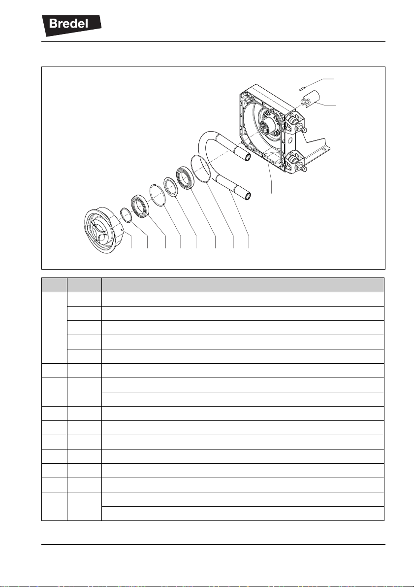
11.1.2 Materials
Pos Description Material
1 Pump housing Aluminium
2 Cover Aluminium
3 Cover window PMMA
4 Pump rotor Cast-iron
5 Pump support Galvanised steel (AISI 316 optional)
6 Bracket AISI 316
7 Fasteners AISI 316
8 Dynamic sealing behind the rotor NBR
9 Cover seal EPDM
10 Sealing bush at hose connection EPDM
11 Coupling Steel
55
Page 56

SPECIFICATIONS
11.1.3 Surface treatment
• After surface preparation, one layer of two-component acrylate is used for
surface protection. Standard colour is RAL 3011.
• All galvanised parts have been provided with an electrolytic zinc layer of 15 - 20
microns.
11.1.4 Lubricant table pump
APEX
Lubricant Bredel Genuine Hose Lubricant
Required quantity [litres] 1.0
Bredel Genuine Hose Lubricant is registered at NSF: NSF Registration N
Category Code H1. Also refer to: www.NSF.org/USDA.
Components:
Glycerol (C
Glycol (C
Water (H
) 50-100% w/w
3H8O3
) 2.5-10% w/w
2H6O2
O)
2
Consult your Bredel representative if you require additional information with
respect to the safety data sheet.
o
123204;
WARNING
It is the users responsibility to ensure the chemical compatibility of the fluid
to be pumped with the lubricant in the pumphead. Obey the local Health
and Safety regulations.
An alternative lubricant is available based on silicone. Also compatibility with this
lubricant must be checked if applied. Refer to the chemical compatibility chart at
www.wmpg.com/chemical or contact your Bredel representative for guidance.
56
Page 57

SPECIFICATIONS
11.1.5 Weights
Description Weight [kg]
Pumphead (inclusive of hose, lubricant and pump support) 17.6
Pump support 2.4
Rotor 4.8 ... 5.6
Hose 0.5 ... 0.7
Pump cover (complete) 1.8
Coupling 0.4
Gearbox coaxial two stages 4.7
coaxial three stages 4.8
worm gearbox 2.4
Electric motor 5.0 ... 8.3
57
Page 58

SPECIFICATIONS
1
5
3
4
2
1
3
2
6
11.1.6 Torque figures
Pos Description Bolt size
*
1Cover M6x25 10
2 Hose clamp
3 Bracket M8x20 25
**
4 Support + Gearbox nut M6 10
5 Drain plug M12x15-PA6 4
6 Inspection window M6x12 1.5
* All steel bolts are class 8.8.
** Due to creeping of the hose material, the hose clamp force initially reduces in time. If
leakage starts, re-tighten the hose clamp to the specified torque level. The listed torque
values apply to a new and properly greased hose clamp. Also refer to § 8.5.3 for extra
instructions and hose clamp installation
58
Torque [Nm]
3
Page 59

11.2 Gearbox
SPECIFICATIONS
Type Coaxial gearbox with helical gears
Number of stages Two or three
Lubrication Lubricated for life
Mounting position IM 3001 (IM B5) flanged gearbox with keyed shaft in horizontal
position.
Motor adapter Integrated
Optional motor adapter Adapter in conformance with IEC-B5 or NEMA C.
* Other gearbox types are available as option.
*
11.3 Electric motor
Standard electric motor design is an enclosed three-phase asynchronous motor. A
thermal safety device to prevent motor overload is optional.
In case of doubt about the local applicable regulations for the drive connection, contact your Bredel representative.
Protection class IP55/IK08
Insulation class F
Increase in temperature Within class B
Voltag e/frequency Refer to identification plate on motor.
59
Page 60

SPECIFICATIONS
11.4 Variable Frequency Drive (VFD) (optional)
The Bredel Variable Frequency Drive (VFD) has been preprogrammed and only needs
to be connected to the mains.
RFI filter Integrated RFI filter B (industrial applications).
Control Manual control for setting the speed and the keys for starting
forward, stop and starting reverse.
Protection class IP65
Mains power supply There are three types available; the choice depends on the
local electricity grid:
• 200-240 V ± 10%; 50/60 Hz ± 5%; 1 ph
• 200-240 V ± 10%; 50/60 Hz ± 5%; 3 ph
• 400-480 V ± 10%; 50/60 Hz ± 5%; 3 ph
11.5 Parts list
11.5.1 Ordering parts
Specify the item number, description and pump size (APEX10, APEX15 or APEX20) to
identify the component you need. Also specify the quantity you need.
60
Page 61

11.5.2 Overview
1
3
2
4,5,6,7
8
SPECIFICATIONS
Pos. Description
1 Cover assembly. Refer to § 11.5.3.
2 Pumphead assembly. Refer to § 11.5.4.
3 Pump support assembly. Refer to § 11.5.5.
4 Barbed nipple assembly. Refer to § 11.5.6.
5 Threaded nipple assembly. Refer to § 11.5.7.
6 Flange assembly (1). Refer to § 11.5.8.
7 Flange assembly (2). Refer to § 11.5.9.
8 Lubricant. Refer to § 11.5.10.
61
Page 62

SPECIFICATIONS
1 24 3
9
8d
8b
8e
8f
5
8c
6
7
8a
11.5.3 Cover assembly
Pos. Qty. Description
1 8 Cover screw
2 8 Cover screw washer
3 1 Drain plug O-ring
4 1 Drain plug
5 1 Breather screw
61Breather
7 1 Breat he r ga s k e t
8a 1 Cover
8b 1 Inspection window
8c 1 Inspection window gasket
8d 6 Inspection window screw
8e 1 Sticker ‘Bredel’
8f 1 Sticker ‘APEX’ (pump size specific)
9 1 Cover seal
62
Page 63
11.5.4 Pumphead assembly
12 17 14 16 15 14 13 10
11
18
19
Pos. Qty. Description
10 1 Hose NR
1Hose NBR
1Hose F-NBR
1Hose EPDM
1Hose CSM
11 1 Pump housing
12 1 Rotor, low-pressure (L)
Rotor, medium-pressure (M)
13 1 Seal ring
14 2 Bearing
15 1 Spacer ring
16 1 Retaining ring
17 1 Circlip
18 4 Support stud
19 1 Coupling, ∅ 20 x 63 mm
Coupling, ∅ 25 x 63 mm
SPECIFICATIONS
63
Page 64

SPECIFICATIONS
20
21
22
23
11.5.5 Support assembly
Pos. Qty. Description
20 1 Pump support
21 4 Support nut
22 4 Support nut washer
23 1 Orientation screw
64
Page 65

11.5.6 Barbed nipple assembly (PTFE/PDVF)
24
25
26
27
29
28
All parts differ for the APEX10, APEX15 and APEX20 except for the
bracket bolt and the bracket bolt washer.
SPECIFICATIONS
Pos. Qty. Description
24 2 Rubber bush
25 2 Hose clamp
26 2 Barbed nipple PTFE
Barbed nipple PVDF
27 2 Bracket
28 4 Bracket bolt
29 4 Bracket bolt washer
65
Page 66
SPECIFICATIONS
24
25
26
2829
27
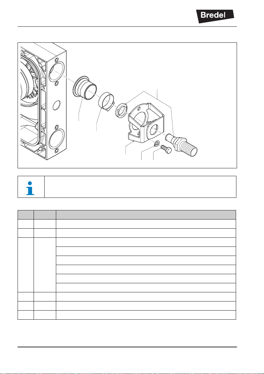
11.5.7 Barbed or threaded nipple assembly (stainless steel/PP/PVC)
All parts differ for the APEX10, APEX15 and APEX20 except for the
bracket bolt and the bracket bolt washer.
Pos. Qty. Description
24 2 Rubber bush
25 2 Hose clamp
26 2 Barbed nipple stainless steel
*
Threaded nipple BSP stainless steel*
Threaded nipple DIN 11851 stainless steel*
Threaded nipple NPT stainless stee l*
Threaded nipple NPT PP
Threaded nipple NPT PVC
27 2 Bracket
28 4 Bracket bolt
29 4 Bracket bolt washer
* A properly created connection between a stainless steel nipple and the pump hose is
EHEDG compliant.
66
Page 67

11.5.8 Flange assembly with insert with collar
24
25
All parts differ for the APEX10, APEX15 and APEX20 except for the
bracket bolt and the bracket bolt washer.
SPECIFICATIONS
29
28
27
32
33
Pos. Qty. Description
24 2 Rubber bush
25 2 Hose clamp
27 2 Flange bracket
28 4 Bracket bolt
29 4 Bracket bolt washer
32 2 Flange ASA
33 2 Insert with collar PP
67
Page 68

SPECIFICATIONS
24
25
26
27
26
31
29
28
32
11.5.9 Flange assembly with threaded nipple
All parts differ for the APEX10, APEX15 and APEX20 except for the
bracket bolt and the bracket bolt washer.
Pos. Qty. Description
24 2 Rubber bush
25 2 Hose clamp
26 2 Threaded nipple (BSP) stainless steel
*
27 2 Bracket
28 4 Bracket bolt
29 4 Bracket bolt washer
31 2 Nipple nut
32 2 Threaded flange DIN stainless steel
2 Threaded flange ASA stainless steel
* A properly created connection between a stainless steel nipple and the pump hose is
11.5.10Lubricant
EHEDG compliant.
Pos. Qty. Description
1 1 l can Bredel Genuine Hose Lubricant
68
Page 69

ORIGINAL
Translation of original certificate
EC DECLARATION OF CONFORMITY OF THE MACHINERY
(according to Annex II.1.A. of Directive 2006/42/EC on machinery)
We,
Watson-Marlow Bredel B.V.
Sluisstraat 7
P.O. Box 47
NL-7490 AA Delden
The Netherlands
herewith declare, on our own responsibility, that the machinery:
Peristaltic hose pump: APEX10-20 series,
for the transportation of various kinds of fluids,
fulfils all the relevant provisions of Directive 2006/42/EC.
and, where appropriate, the machinery complies with the harmonised standard(s), other
standards or technical specifications, applicable requirements of these standards and/or
specifications as listed below:
EN 809
EN-ISO 12100-2
NEN-EN-IEC60204-1
Authorised to compile the technical file:
J. van den Heuvel, Sluisstraat 7, 7491GA, Delden, The Netherlands
The Netherlands, Delden
1 March 2013
J. van den Heuvel
Managing Director
69
Page 70

SAFETY FORM
Safety form
SAFETY FORM
Product Use and Decontamination Declaration
In compliance with the Health and Safety Regulations, the user is required to declare those substances that
have been in contact with the item(s) you are returning to W atson-Marlo w Bredel B.V. or any of its subsidiaries or
distributors. Failure to do so will cause delays in servicing the item or in issuing a response. Therefore, please
complete this form to make sure we have the information before receipt of the item(s) being returned. A completed copy must be attached to the outside of the p ackaging cont aining the item(s). You, the user , are responsible for cleaning and decontaminating the item(s) before returning them.
Please complete a separate Decontamination Certificate for each item returned. RGA/KBR no...................
1 Company ............................................................. .........................................................................................
Address .................... ............. ........... ............. ....... .......................... ............. ........... .......................................
Postal code.................................................. .. ... ....
Telephone.............................................................
2 Product ................................................................ 3.4 Cleaning fluid to be used if residue of chemical is
2.1 Serial Number ............. ... .. ... .................................
2.2 Has the Product been used?
YES NO
If yes, please complete all the following para-
graphs.
If no, please complete paragraph 5 only
3 Details of substances pumped 4 I hereby confirm that the only substances(s) that
3.1 Chemical Names
a) ............................ .......... ............. ........... ............
b) ............................ .......... ............. ........... ............
c) ............................ ............................. .................
d) ............................ .......... ............. ........... ............
3.2 Precautions to be taken in handling these substances:
a) ............................ .......... ............. ........... ............
b) ............................ .......... ............. ........... ............
c) ............................ ............................. .................
d) ............................ .......... ............. ........... ............
3.3 Action to be taken in the event of human contact:
a) ................ .........................................................
b) ................ .........................................................
c) .........................................................................
d) ................ .........................................................
Fax number ................................... ... ... .................
found during servicing;
a) ........................................................................
b) ........................................................................
c) ............................... ... .................................... ..
d) ........................................................................
the equipment specified has pumped or co me in to
contact with are those named, that the information
given is correct, and the carrier has been informed
if the consignment is of a hazardous nature.
5 Signed .................................................................
Name ........................ ....................... ....................
Position .......................... ..... ........ ........ ........ ....... ..
Date .......................... ....................... ....................
Note:
To assist us in our servicing please describe
any fault condition you have witnessed.
.............................................................................
.............................................................................
.............................................................................
.............................................................................
.............................................................................
Page 71

Notes
NOTES
NOTES
71
Page 72

Watson-Marlow Bredel B.V.
Environmental
Management
ISO
14001
Quality
Management
ISO
9001
P.O. Box 47
NL-7490 AA Delden
The Netherlands
Telephone: +31 (0)74 3770000
Fax: +31 (0)74 3761175
E-mail: bredel@wmpg.com
Internet: http://www.bredel.com
72
29210320 TS11-003-B
© 2014 Watson-Marlow Bredel B.V.
 Loading...