

Page 1

Installation and Operating Instructions
Software Version 6.1
5O5XY Robot
PB0193 Issue 3
Page 2

Contents
505XY one-year warranty .................................................... Page 3
Safety .................................................... Page 3
Information for returning the robot ................................................... Page 3
Part 1: Installation
Siting .................................................... Page 4
Electrical connection .................................................... Page 4
Interfacing with the 505Di .................................................... Page 4
505Di setup procedure .................................................... Page 5
Dispensing head .................................................... Page 7
Part 2: Overview
Quick start for a pre-programmed robot ........................................... Page 8
Keypad layout .................................................... Page 8
Conventions used in the manual .................................................... Page 8
Part 3: Setup
Accessing the setup mode .................................................... Page 9
Selecting a language .................................................... Page 9
Clearing memory .................................................... Page 9
Remote control operation .................................................. Page 10
Exit setup mode .................................................. Page 10
Part 4: Setting the operating parameters
Requirements .................................................. Page 11
Setting the number of rows and columns ...................................... Page 11
Setting the tray fill pattern .................................................. Page 12
Setting up the drip delay and fill head speed ................................ Page 12
Setting the operating mode .................................................. Page 13
Setting the number of trays and the fill direction ........................... Page 14
Storing values and returning to the main menu ............................. Page 14
Setting batch fill delays .................................................. Page 15
Multiple tray setup .................................................. Page 15
Setting the XY robot filler start/end/corner points .......................... Page 15
The start point .................................................. Page 16
The end point .................................................. Page 16
The corner point .................................................. Page 17
Part 5: Operating the 505XY
Performing a test fill .................................................. Page 18
Fill in conjunction with the 505Di/L or 505Di/RL ............................ Page 18
Part 6: Memory facilities
Storing/recalling/reviewing memories ............................................ Page 20
Storing a setup in memory location ............................................... Page 20
Recalling memories .................................................. Page 21
Reviewing memories .................................................. Page 21
Error messages .................................................. Page 21
Specification .................................................. Page 22
Fill pattern examples .................................................. Page 23
Menu structure .................................................. Page 24
Outline dimensions .................................................. Page 27
Product Use and Decontamination Declaration ............................. Page 28
Declaration of Conformity .................................................. Page 29
2
Page 3
505XY one-year warranty
Watson-Marlow Limited warrants, subject to the conditions below, through
either Watson-Marlow Limited, its subsidiaries, or its authorised distributors,
to repair or replace free of charge, including labour, any part of this product
which fails within one year of delivery of the product to the end user. Such
failure must have occurred because of defect in material or workmanship
and not as a result of operation of the product other than in accordance with
the instructions given in this manual.
Conditions of and specific exceptions to the above warranty are:
· Consumable items are excluded.
· Products must be returned by pre-arrangement carriage paid to Watson-
Marlow Limited, its subsidiaries, or its authorised distributor.
· All repairs or modifications must have been made by Watson-Marlow
Limited, its subsidiaries, or its authorised distributors or with the express
permission of Watson-Marlow Limited, its subsidiaries, or its authorised
distributors.
· Products which have been abused, misused, or subjected to malicious or
accidental damage or electrical surge are excluded.
Warranties purporting to be on behalf of Watson-Marlow Limited made by
any person, including representatives of Watson-Marlow Limited, its
subsidiaries, or its distributors, which do not accord with the terms of this
warranty shall not be binding upon Watson-Marlow Limited unless expressly
approved in writing by a Director or Manager of Watson-Marlow Limited.
Safety
In the interests of safety, this unit should only be used by competent, suitably
trained personnel after they have read and understood this manual, and
considered any hazard involved.
Any person who is involved in the installation or maintenance of this
equipment should be fully competent to carry out the work. In the UK this
person should also be familiar with the Health and Safety at Work Act 1974.
Do not place any part of the body within the working envelope of the 505XY
during operation.
There are dangerous voltages (at mains potential) inside the unit. If access is
required, isolate from the mains supply before removing the cover.
Information for returning the robot
Any equipment which has been contaminated with, or exposed to, body
fluids, toxic chemicals or any other substance hazardous to health must be
decontaminated before it is returned to Watson-Marlow or its distributor.
A certificate (a suitable blank form is included at the rear of these operating
instructions), or signed statement, must be attached to the outside of the
shipping carton.
This certificate is required even if the equipment is unused. If the 505XY has
been used, the fluids that have been in contact with the 505XY and the
cleaning procedure must be specified along with a statement that the
equipment has been decontaminated.
3
Page 4
Part 1: Installation
Siting
The 505XY should be situated on a flat surface and is fitted with adjustable
feet to ensure that the unit can be levelled. Adequate area must be given to
allow tubing to pass from the 505L pumphead to the dispensing head of the
robot without kinking or unnecessary bends.
Electrical connection
The 505XY operates on single phase mains electricity only. It is fitted with a
mains voltage selector which must be set to either 120V for 100-120V
50/60Hz supplies or 240V for 220-240V 50/60Hz supplies.
The on/off switch of the 505XY is located at the mains socket as is the fuse.
A spare fuse is incorporated in the fuse holder and should be replaced with
the same value of fuse if used.
A mains cable fitted with a moulded plug is supplied with the 505XY, but if
another plug is to be fitted, the colour coding of the mains lead must be
observed.
The mains cable for 220-240V supplies is coded so that the live lead is
coloured brown, the neutral lead is coloured blue, and the earth lead is
coloured green and yellow.
The mains cable for 100-120V supplies is coded so that the live lead is
coloured black, the neutral lead is coloured white, and the earth lead is
coloured green.
Failure to
operate
Should the robot fail to operate, check that mains electricity is available at
the unit, that the voltage selector switch is in the correct position and that the
mains fuse is in tact.
There are dangerous voltages (at mains potential) inside the unit. If
access is required, isolate the pump from the mains before removing
the cover.
Interfacing with the 505Di
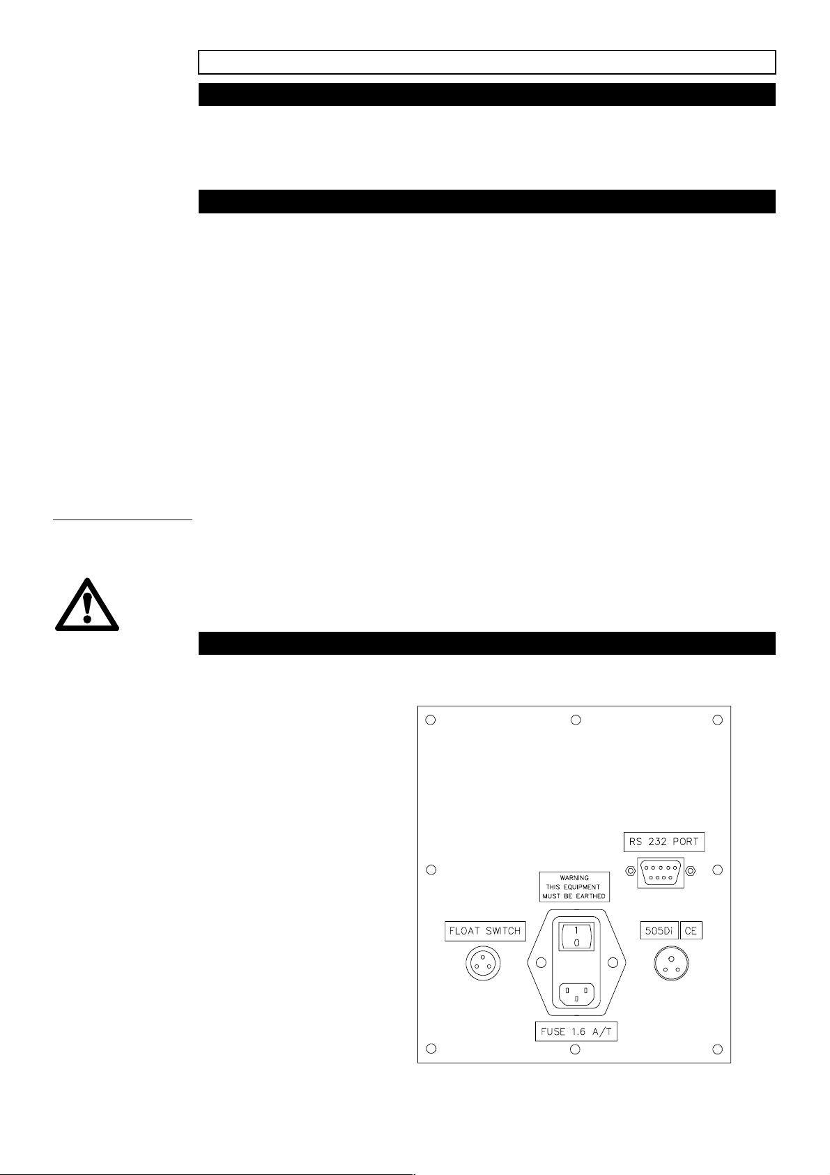
The 505XY has four connector/sockets on the rear panel.
· Mains socket
· 505Di socket
· RS 232 connector
· Floatswitch socket
4
Page 5
· Ensure that the voltage selector, found on the underside of the unit, is
switched to the appropriate voltage - either 120V for 110V-120V
operation, or 240V for 220-240V operation.
· Plug the mains power lead into mains socket at rear of unit.
· Level the robot using the adjustable feet.
· Connect the interface lead into socket at rear of unit marked 505Di
socket. Connect the other end into the 25 pin Dee connector on the rear
panel of the 505Di using the interface lead provided, Watson-Marlow part
number 059.7021.000.
· An RS 232 connector is provided to allow connection to a P.C. for remote
control.
· The float switch socket enables a remote stop facility to be set up
providing an over-ride to a preset dispensing run.
· Attach the delivery end of the tubing from the 505L pumphead to the
dispensing head of the XY Robot.
505Di setup procedure
The 505Di which is to be used in conjunction with the 505XY should be fitted
with EPROM version 2.03.
Ensure that mains power to the 505Di is on and the interface lead to the
505XY is correctly in position. The main menu of the pump will display:
D D S E C A L M A N U A L
N E T W O R K S E T U P
Step to SETUP and press Enter.
R O M D A T E / T I M E
B E E P R A M P D R I P >
B A U D = 9 6 0 0 A U X I L
P U M P = 1 M A X >
Using the step key, step through to AUXIL and press Enter, you will be given
an option under Line 1 of Dose or Motor:
L I N E 1
D O S E M O T O R
Press Enter at Dose.
The pump will then display the following message:
L I N E - 1
H I G H = R U N S T O P
5
Page 6
Step to Stop and press Enter.
L I N E - 2 D I R E C T I O N
H I G H = C W
Press Enter at CW. The pump can be set to operate in a counter-clockwise
or clockwise direction for this setup procedure. The following screens will
then be called:
L I N E - 1 H I G H = S T O P
L I N E - 2 H I G H = C W
B A U D = 9 6 0 0 A U X I L
P U M P = 1 M A X >
Press Main Menu calling up the display:
D D S E C A L M A N U A L
N E T W O R K S E T U P
The 505Di can now be calibrated and the dosing parameters set in the
normal way. (For more information reference the 505Di operating instruction.
It is a recommended that a trial run of the 505XY setup is completed before
full process operation. This will ensure that the traversing limits of the 505XY
have been programmed correctly. (Refer to Part 5 of this operating
instruction).
Following calibration and dose setup the pump screen will indicate:
* * * *
M L
* * * * *
D O S E
P R E S S S T A R T
The GO button can then be pressed on the 505XY Robot and dispensing will
commence.
The 505Di should be set up normally as if for a manual dispensing run. The
505XY robot filler controls when the pump should start dispensing ensuring
that the pump will always wait for the dispensing head to finish moving to the
next position before it starts pumping again.
Note: If the 505Di setup is complete and the pump is ready to start a
dispensing cycle, turning the mains power of the 505XY robot on or off will
initiate a single dose from the 505Di.
6
Page 7
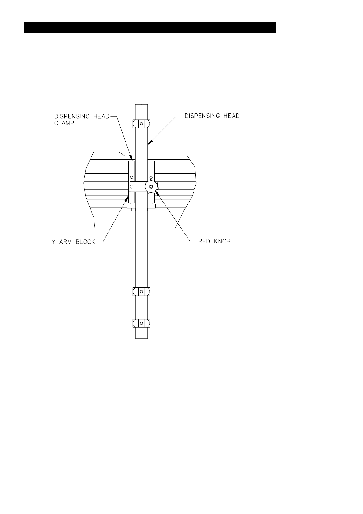
Dispensing head
The appropriate dispensing head for the size of tubing being used should be
attached to the Y arm block by loosening the red knob and lifting the
dispensing head clamp.
The dispensing head can then be inserted into the slot, the clamp lowered
and the red knob re-tightened.
In order to obtain the correct dispensing height, adjustable feet are fitted to
the base of the system.
An adjustable tray guide is also fitted to ensure that the filler trays locate
correctly.
Fine adjustment can be made using the dispensing head. It can be raised or
lowered by simply undoing the adjustable red knob, and sliding the guide to
the correct (200mm max) height, then re-tighten.
7
Page 8
Part 2: Overview
Quick start for a pre-programmed robot
To initiate a fill sequence on a pre-programmed XY robot filler switch on
power to the unit and the following screen will be displayed:
S O F T W A R E V E R X . X
M E M O R Y S E T U P G O
Ensure that the vial tray is located correctly within the tray guides
and press the 'GO' button to begin a fill cycle.
The remainder of the manual explains how to program the system
for a variety of filling applications using different tray sizes and
equipment configurations.
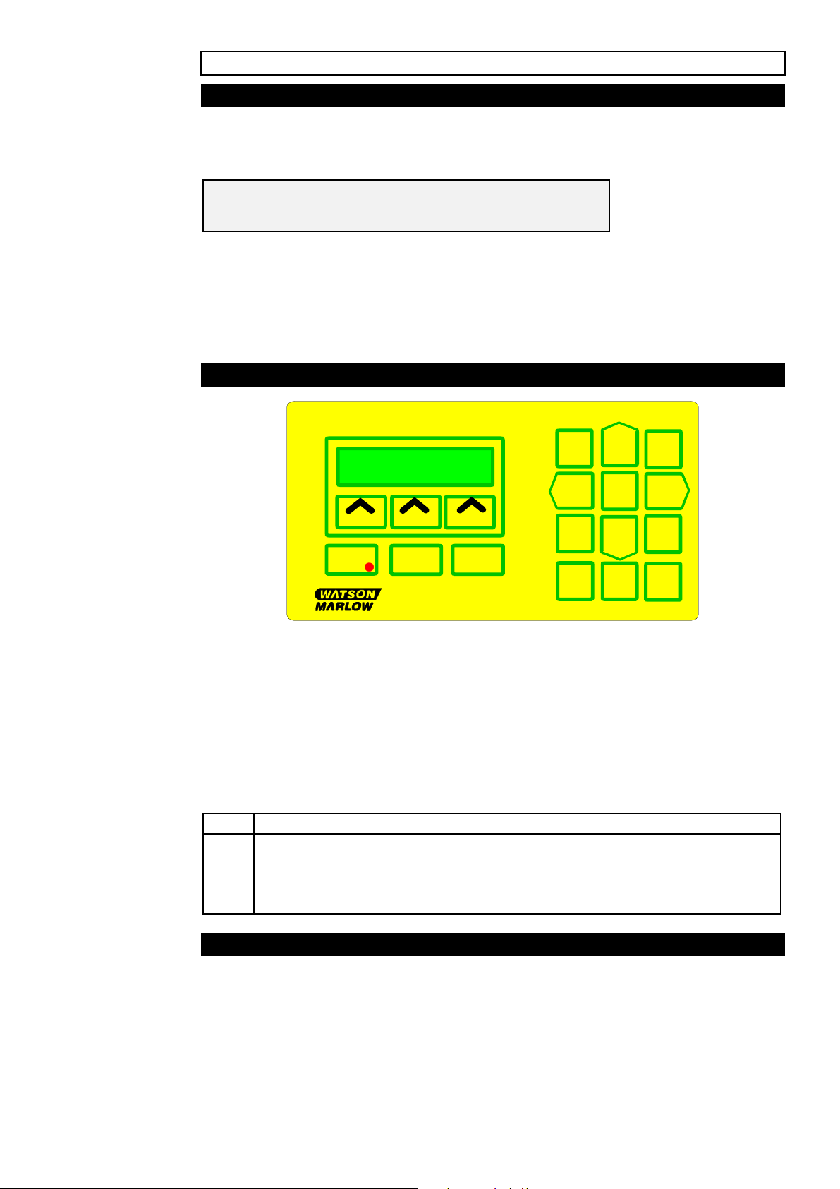
Keypad layout
1
4
7
Power
Start
505XY
Beneath the display are three rectangular soft function keys. The function of
each key at any one time in a procedure is denoted by the text in the bottom
line of the LCD display.
The keypad serves two functions;
· To enable parameters to be entered into the operating programme of the
XY robot.
· To enable the operator to move the fill head
· The keys and functions are listed below::
Key Function
2 Move fill head to fill rear of XY robot filler
4 Move fill head left
6 Move fill head right
8 Move the fill head forwards (towards the front of the XY robot filler)
Stop
Enter
Robot
2
5
8
0
3
6
9
.
Conventions used in the manual
Throughout the manual conventions are used to describe the keyboard keys:
The soft keys are referred to as 'buttons', e.g. from the main menu press the
MEMORY button.
The keypad keys and the START/STOP keys are shown enclosed thus
<START>.
8
Page 9

Part 3: Setup
Accessing the setup mode
This section illustrates how various parameters such as language used and
serial communication speed are set up upon receipt of a new machine. It
also shows that this procedure need only be carried out once, as all
parameters are stored, even when the unit is switched off.
Setup mode is accessed by holding down the soft key, which is positioned to
the extreme left of the three keypad softkeys, whilst the power is switched on
at the rear of the machine. When the key is released the display will show
the following message:
S E T U P P R O G R A M M E
E N T E R P A S S W O R D
Enter the system password (1212) the display will show the following
message:
S E T U P P R O G R A M M E
C O U N T R Y M E M O R Y N E X T
Selecting a language
Press the key beneath the "country" option on the display. The display will
show the following message:
E N G L I S H N E X T A C C E P T
Press the NEXT button to step through each available language option.
Press ACCEPT to select the desired option and return to the setup menu.
Clearing memory
NOTE. This should only be necessary after maintenance work or after a
software upgrade. This operation will erase all settings stored in the
module.
At the setup menu press the MEMORY button. The display will show the
following message:
E R A S E M E M O R Y
A C C E P T Q U I T
Press the ACCEPT button to erase all memory locations, or the QUIT button
to cancel the operation and return to the setup menu. After pressing the
NEXT button, the display will show:
9
Page 10

S E T U P P R O G R A M M E
R S 2 3 2 R E M O T E N E X T
Press the RS232 button, the display will show:
1 2 0 0 B P S N E X T A C C E P T
Press the NEXT button until the desired baud rate is shown in the display.
Press the ACCEPT button to store the selected value. The previous setup
menu will be displayed.
Remote control operation
Press the REMOTE button, the display will show:
X Y K E Y P A D M O D E
N E X T A C C E P T
Press the NEXT to alternate between XY keypad and XY remote mode,
followed by the ACCEPT button to store the selected value and return to the
setup menu.
NOTE: After selecting XY remote mode, the keypad will become redundant,
all control will be via a remote keypad. For diagnostic help, refer to the
engineering mode flow chart on page 24.
Exit setup mode
To exit the setup mode press the ACCEPT button, the XY robot filler will
reset and display the following screen, prompting to press <START> to move
the dispensing head to the home position.
P R E S S < S T A R T >
T O H O M E M A C H I N E
When the dispensing head has been moved to the home position the main
menu will be called:
S O F T W A R E V E R X . X
M E M O R Y S E T U P G O
10
Page 11

Part 4: Setting the operating parameters
Requirements
Before a fill sequence the XY robot filler needs to know the following:
1. Size of fill in rows & columns.
2. Fill pattern, the way the tray of bottles are arranged.
3. The delay from the end of dispensing liquid to moving to the next fill point
drip delay.
4. The speed at which the head will move from one fill point to the next.
5. Whether the XY robot filler will run continuously after finishing a fill pattern
or stop.
6. The number of trays to be placed within the working envelope.
7. The direction of the fill sequence.
8. The start point for each tray.
9. The end point, for each tray position.
10.The corner point, for each tray position.
Setting the number of rows and columns
Initially the screen will show:
S O F T W A R E V E R X . X
M E M O R Y S E T U P G O
Press the SETUP button and the display will show:
S E T U P / T E S T T R A Y N O 1
T E S T L I M I T S O P T I O N S
From the setup menu select OPTIONS, calling the display:
S E T U P F I L L O P T I O N S
C O L U M N S R O W S N E X T
P R E S S E N T E R T O R E T
C O L U M N S R O W S N E X T
The option to return to the previous setup/test menu will also toggle with this
display.
Press the COLUMNS button to call the display:
E N T E R N O O F C O L S 0 0
A C C E P T Q U I T
11
Page 12

The display will show the previously entered value (if any). Enter the
number of columns to be filled using the keypad (between 01 & 99). Press
the ACCEPT button to store the value, or the QUIT button to return to the
previous setup/fill/options menu without changing any settings. Press the
ROWS button to call the display:
E N T E R N O O F R O W S 0 0
A C C E P T Q U I T
Again, using the keypad, enter the number of rows to be filled and press the
ACCEPT button to store the value, or the QUIT button to return to the
previous setup/fill/options menu without changing any settings.
NOTE: Using the QUIT button provides a quick verification of the set number
of rows and columns.
Press the NEXT button, the display will show:
S E T U P F I L L O P T I O N S
P A T T E R N D R I P D E L N E X T
P R E S S E N T E R T O R E T
P A T T E R N D R I P D E L N E X T
The option to return to the previous setup/fill/options menu will also toggle
with this display.
Setting the tray fill pattern
The XY robot may, in addition to a straight fill, perform fill sequences on
trays with bottles arranged in a honeycomb pattern. Four distinct patterns
are available and these are shown on page 23, together with their
associated start/end points and number of columns/rows.
Press the PATTERN button, the display will show:
0 0 0 0 0 0 S T R A I G H T F I L L
0 0 0 0 0 0 N E X T A C C E P T
The display will show the previously entered fill pattern (if any), if no pattern
was previously stored the straight pattern will be displayed.
Press the NEXT button to scroll through the available fill patterns, press the
ACCEPT button to store the desired pattern. The previous setup/fill/options
menu will then be displayed.
Setting up the drip delay and fill head speed
The drip delay, is the time period between the XY robot filler completing one
delivery, and moving to the next fill point. Press the DRIPDEL button and the
display will show:
12
Page 13

D R I P D E L A Y 0 . 1 S
A C C E P T Q U I T
The previously entered drip delay (if any) will be shown. Enter the drip delay
in multiples of 0.1 seconds and press either the ACCEPT button to store the
new value, or the QUIT button to return to the previous setup/fill/options
menu without making any changes.
NOTE: Using the QUIT button provides quick verification of drip delay.
Press the NEXT to call the display:
S E T U P F I L L O P T I O N S
S P E E D M O D E N E X T
P R E S S E N T E R T O R E T
S P E E D M O D E N E X T
The option to return to the previous setup/fill/options menu will also toggle
with this display.
Press the SPEED button, the display will show:
S E T P O S I T I O N E R S P E E D
X . X C M / S N E X T A C C E P T
Use the NEXT button to select the desired filler head traversing speed.
Options of 6, 9 or 12cm/s are available. Press the ACCEPT button to store
the selected speed and return to the previous setup/fill/options menu.
Setting the operating mode
There are two modes of operation with the XY robot. Batch mode is where the
XY robot will perform a fill sequence and then stop, whilst continuous mode is
where the XY robot will repeat its fill sequence until stopped manually.
Press the MODE button, the display will show:
B A T C H M O D E
N E X T A C C E P T
Press the NEXT button to change the operating mode to continuous. Press
the ACCEPT button to store the selected mode and the previous
setup/fill/options menu will be displayed.
Press the NEXT button, the display will show:
13
Page 14
S E T U P F I L L O P T I O N S
T R A Y S S T E P D I R N E X T
P R E S S E N T E R T O R E T
T R A Y S S T E P D I R N E X T
The option to return to the previous menu will also toggle with this display.
Setting the number of trays and the fill direction
In order for the XY robot to operate correctly, it needs to know the number of
individual trays within the working envelope which are to be part of a fill
sequence.
For example, if three tray positions have been programmed into the system
setup, and all three are to be filled, then by setting the number of trays as 3,
all three trays will be filled.
If however, only tray 1 of the three trays was required to be filled, then by
setting the number of trays as 1 then this will be achieved.
This is a general setting applicable to fill sequences which can be set under
any individual tray setup option.
Press the TRAYS button, the display will show:
N O O F T R A Y S 1
A C C E P T Q U I T
Use the numeric keypad to enter the number of trays to be filled. Press the
ACCEPT button to exit and store the value, or the QUIT button to exit
without changing anything. The previous menu will be displayed.
Storing values and returning to the main menu
The XY robot can work either forwards (starting at the start point), or
backwards (starting at the end point). Press the STEP-DIR button, the display
will show:
N O R M A L T R A Y S T E P
A C C E P T N E X T
With NORMAL TRAY STEP displayed as shown below, the XY robot will
start at the nearest point to home and proceed from there.
Press the NEXT button to change the option to REVERSE TRAY STEP.
R E V E R S E F I L L
A C C E P T N E X T
Press the ACCEPT button to exit and store the selection and the previous
setup/fill/options menu will be displayed.
14
Page 15

Press the NEXT to call the following screen:
S E T U P F I L L O P T I O N S
D E L A Y N E X T
Setting batch fill delays
Press the DELAY button and the display will show:
B A T C H F I L L D E L A Y O O S
A C C E P T Q U I T
Set the time delay between each batch fill sequence in seconds using the
numeric keypad. Press ACCEPT to store the value or QUIT to return to the
previous display without changing any settings.
When all parameters have been entered the program will return to the setup
menu, from here press <ENTER> to return to the main menu.
If the limits have been set outside the fill area, or the start is further than the
end point an appropriate error message will appear on the display for
approximately 1.5 seconds. These setting errors must be rectified before
the program will return to the main menu.
Multiple tray setup
The setup for multiple trays within the fill area is identical to the setup of an
individual tray. Each individual setup procedure must be repeated for the
relevant position of each individual tray. Each tray number should be
entered at the following screen prior to its positional information being
inputed. Fill tests on specific trays can be carried out by entering the relevant
tray number and then running the fill test procedure.
S E T U P / T E S T T R A Y N O 1
T E S T L I M I T S O P T I O N S
The "1" in the figure above shows that the limits for a tray No.1 can be
changed. Pressing the <2> key will increase the number up to a maximum of
nine pressing the <8> key will decrease the number back down to "1".
Setting the XY robot filler start/end/corner points
S E T U P / T E S T T R A Y N O 1
T E S T L I M I T S O P T I O N S
Press the LIMITS button and the following display will be called:
S E T F I L L L I M I T S - 1
S T A R T E N D C O R N E R
15
Page 16

P R E S S E N T E R T O R E T
S T A R T E N D C O R N E R
The option to return to the previous setup/test menu will also toggle with this
display.
The start point
NOTE. The start point is always nearest the home position. When using a
honeycomb fill pattern refer to page 23 for an illustration of various patterns
and start/end points.
Press the START button, the display will show:
M O V E T O S T A R T P O I N T
A C C E P T Q U I T H O M E
The fill head will move to the previously set start point. Using the keypad
cursor keys move the fill head to the first fill point.
Press the ACCEPT button to store the setting. The XY robot will warn the
operator that the Y corner point has been reset by calling the display:
Y C O R N E R P O I N T R E S E T
Press the HOME button to move the fill head to the home position, or the
QUIT button to return to the previous menu without changing any settings.
NOTE. If the start point is moved, the end point will move with respect to the
change in co-ordinates. This is useful if the same tray is used but positioned
in a different position as the start point is then the only change required.
The end point
Press the END button, the display will show:
M O V E T O E N D P O I N T
A C C E P T Q U I T H O M E
The fill head will move to the previously set end point. Using the keypad
cursor keys move the fill head to the last fill point. Press the ACCEPT button
to store the setting. The XY robot will warn the operator that the X corner
point has been reset by calling the display:
X C O R N E R P O I N T R E S E T
16
Page 17

Press the HOME button to move the fill head to the home position, or the
QUIT button to return to the previous set fill limits menu without changing any
settings.
The corner point
The corner point feature is generally the point furthest away (in a horizontal
line) from the first fill point. When using a honeycomb fill pattern refer to
page 23 for an illustration of various patterns and start/end points.
NOTE: The corner point will be calculated by the robot and will generally not
need altering. The feature is included to allow for possible tray misalignment.
Press the CORNER button, the display will show:
M O V E T O C O R N E R P O I N T
A C C E P T Q U I T H O M E
The fill head will move to the corner point which has been calculated using
the START and END point settings. If tray misalignment is experienced use
the cursor keys to move the fill head to the actual corner point (the point
furthest left along the first fill row).
Press the HOME button to move the fill head to the home position, or the
QUIT button to return to the previous menu without changing any settings.
Press the <ENTER> key to return to the set fill limits menu. Within the setup
menu option the <2>and <8> keys can be used to select any one of a
number of possible trays within the fill area. Please refer to the section
covering multiple tray setup.
17
Page 18

Part 5: Operating the 505XY
Performing a test fill
Press the SETUP button, the display will show:
S E T U P / T E S T T R A Y N O 1
T E S T L I M I T S S I Z E
The display shows that the LIMITS and TEST options refer to tray No 1,
pressing key <2> increases the value up to 9, pressing key <8> decreases
the value down to 1. With the tray number shown as '1', pressing key <8>
will change the display to 'TEST ALL TRAYS', this allows the testing of the
programmed fill sequence for the number of trays entered.
Press the TEST button, the display changes to show the fill status:
0 0 : R X C F F T R A Y X
· 00 is the number of the current memory setup.
· R is the programmed number of rows in the tray.
· C is the programmed number of columns in the tray.
· FF is the tray fill pattern, e.g.
ST = Straight
H1 - H4 = Honeycomb
· TRAY X shows the tray number that is currently being filled.
A test fill sequence is now performed with the head passing over the
vials/bottles without the XY robot operating.
If at anytime the fill sequence must be stopped, press STOP, the display
changes to the pause screen:
P O S I T I O N E R P A U S E D
R E S U M E A B O R T
Press the RESUME button or the <START> key to continue. Press the
ABORT button to stop the test pattern.
The fill head moves to the home position after the sequence has finished or
if the sequence is aborted.
Fill in conjunction with the 505Di/L or 505Di/RL
Connect the dispenser to the XY robot using the 3 pin cable.
Setup the XY robot or load a setup from memory.
At the main menu press the GO button, the fill sequence will now begin and
the display changes to show the final status:
18
Page 19

0 0 : R X C F F T R A Y X M
M O D E
· M is the operating mode Batch/Continuous.
Pressing the MODE button will change the operating mode from Batch to
Continuous or vice versa.
If at any time the fill sequence must be stopped follow the procedure shown
on the previous page, otherwise the fill head will move to the home position
after the sequence has finished or if it is aborted.
If the XY robot detects an error in the signal from the 505Di the display will
change to show:
W A I T I N G F O R P U M P
R E S U M E A B O R T
Check the connections between the XY robot and the 505Di.
Press the RESUME button to continue or the ABORT button to reset the XY
robot and finish the fill sequence.
19
Page 20

Part 6: Memory facilities
Storing/recalling/reviewing memories
The XY robot has the ability to store and recall up to 50 settings, each setting
may have up to 20 character descriptions attached to it in order to describe
the type of fill, tray size etc. All operating information for the XY robot is
stored in a memory location, including the language in use as well as the
head speed and serial interface speed.
S O F T W A R E V E R X . X
M E M O R Y S E T U P G O
Press the MEMORY button to call the following screen:
R E C A L L / S T O R E / R E V I E W
R E C A L L S T O R E R E V I E W
P R E S S E N T E R T O R E T
R E C A L L S T O R E R E V I E W
The option to return to the previous main menu will also toggle with this
display. Press the ENTER key to return to the main menu.
Storing a setup in memory location
From the memory menu press the STORE button, the display will show:
S T O R E M E M O R Y N O 1
A C C E P T Q U I T
Enter the memory number in which you wish to store the current setup, using
the numeric keypad. Press the ACCEPT button to store the setup, or the
QUIT button to return to the previous memory menu. When the ACCEPT
button is pressed the operator is taken to the memory description screen as
shown below:
2 4 : 3 X 4 S T T R A Y 2 M
A C C E P T Q U I T
The display will show the current description stored for that location, or if the
location was previously unused the XY robot will suggest a description for
you as shown above, the format being the same as the status line when the
XY robot is operating. When the unit offers a description for a setup which is
being stored into a memory location, ensure that the description is different
from any previously stored setups to avoid any programs being overwritten.
Use the <4> and <6> keys to move the cursor left and right and the <2> and
<8> keys to increase or decrease the character to the left of the cursor.
20
Page 21

Pressing the <5> key will copy the character to the left of the cursor to the
current cursor position. Press the ACCEPT button to store the description.
The operator is returned to the memory menu.
Recalling memories
From the memory menu press the RECALL button, the display will show:
R E C A L L M E M O R Y N O 0 1
A C C E P T Q U I T
Enter the memory number to recall using the numeric keypad, press the
ACCEPT button to recall the setup, or the QUIT button to return to the
previous memory menu. If the memory number entered does not contain a
valid setup, then the display will show:
* * * E R R O R * * *
M E M O R Y I S E M P T Y
Re-enter a valid memory location number, or use the REVIEW button, as
described below, to select from the valid memories stored.
Reviewing memories
Press the REVIEW button, the display will show:
0 0 : R X C F F T R A Y X M
N E X T Q U I T R E C A L L
This is the description attached to memory location 01, pressing the NEXT
button moves to the next location with a valid setup stored in it, when the last
stored location is displayed and the NEXT button is pressed, the first
location is redisplayed. Press the RECALL button to load the contents of the
selected memory location and return to the main menu. Press the QUIT
button to return to the memory menu without recalling the memory location.
Error messages
If an attempt has been made to load an empty memory location, the display
will show:
* * * E R R O R * * *
M E M O R Y I S E M P T Y
Re-enter a valid number or use REVIEW to select. If 0 is entered as a
memory number or a the number of rows or columns the display will show:
* * * E R R O R * * *
O N L Y 0 1 - 5 0 A L L O W E D
21
Page 22

A memory number, or the number of rows/columns as has been entered as
0. Re-enter with a number between 01 and 50.
If the calculated fill area exceeds the area the XY robot can cover then
display will call:
I N V A L I D S T A R T O R E N D
P O I N T S - R E S E T L I M I T S
This can be a result of changing the START point when the END is near the
left hand limit or selecting a honeycomb pattern which has a fill point outside
the available fill area.
If the set START point is to the left of the END point the display will call:
I N V A L I D S T A R T / F I N I S H
P O I N T S - R E S E T L I M I T S
Reset so that the START point is to the right of the END point.
Specification
Power supply 110/120V&220/240V 50/60Hz Single phase
Power consumption 40W
Fuse rating T type 1.6A
Electronics Microprocessor controlled
Number of memories 50
Languages English, French, German, Spanish &
Italian(selectable)
In/Out ports Float switch, Serial RS232 300,600 1200,
2400,4800, 9600 Baud (selectable)
Dimensions Width 735mm x height 280mm x depth 385mm
Weight 14Kg
Number of fill points 99 (X), 99 (Y).
Fill patterns Straight & 4 Honeycomb patterns
Fill head speed 120mm/Sec (selectable 60, 90, 120mm/Sec,
excluding acceleration and deceleration times)
Fill direction Normal (start at start point) or Reverse (start at
end point)
Fill area 420x245 (Between fill centres)
Operating mode Batch (finishes after filling all trays), Continuous
(repeats the fill tray sequence until reset)
Positional accuracy Better than 0.3mm
Drip delay 0.0 - 0.9 Seconds (increment 0.1seconds)
Number of trays 9
Maximum vial height 200mm
Minimum vial diameter 6.5mm
22
Page 23

Fill pattern examples
23
Page 24

Menu structure
Depress and hold any of the soft keys whilst switching on the XY robot, then
release and, at the prompt, enter 1212 as the password.
SETUP PROGRAM
ENTER PASSWORD
SETUP PROGRAM
COUNTRY MEMORY NEXT
SETUP PROGRAM
ENGLISH NEXT ACCEPT
SETUP PROGRAM
FRENCH NEXT ACCEPT
SETUP PROGRAM
GERMAN NEXT ACCEPT
SETUP PROGRAM
SPANISH NEXT ACCEPT
SETUP PROGRAM
ITALIAN NEXT ACCEPT
ERASE MEMORY
ACCEPT QUIT
SETUP PROGRAM
300BPS NEXT ACCEPT
SETUP PROGRAM
600BPS NEXT ACCEPT
SETUP PROGRAM
1200BPS NEXT ACCEPT
SETUP PROGRAM
2400BPS NEXT ACCEPT
SETUP PROGRAM
4800BPS NEXT ACCEPT
SETUP PROGRAM
RS232 REMOTE NEXT
SETUP PROGRAM
NEXT ACCEPT
XY KEYPAD MODE
NEXT ACCEPT
XY REMOTE MODE
NEXT ACCEPT
SETUP PROGRAM
960BPS NEXT ACCEPT
NOTE: Once the remote keypad option has been selected, the XY robot
keypad will become redundant.
In order to regain control, the keypad mode must be reselected. This may
only be done by switching off the machine and returning to the set-up mode
as detailed above.
24
Page 25

SOFTWARE VER X.X
MEMORY SETUP GO
PRESS ENTER TO RETURN
RECALL/STORE/REVIEW
RECALL/STORE/REVIEW
00: RxC FF TRAY X
MOVE TO START POINT
ACCEPT QUIT HOME
NUMBER OF COLUMNS 01
ACCEPT QUIT
SETUP/TEST TRAY NO. X
TEST LIMITS OPTIONS
SET FILL LIMITS-1
START END CORNER
MOVE TO END POINT
ACCEPT QUIT HOME
SETUP FILL OPTIONS
COLUMNS ROWS NEXT
NUMBER OF ROWS 01
ACCEPT QUIT
00: RxC tray x M
MODE
MOVE TO CORNER POINT
ACCEPT QUIT HOME
SETUP FILL OPTIONS
PATTERN DRIP DEL NEXT
25
Page 26

SETUP FILL OPTIONS
N
PATTERN DRIP DEL NEXT
PRESS ENTER TO RETUR
STRAIGHT FILL
NEXT ACCEPT
HONEYCOMB 1
NEXT ACCEPT
HONEYCOMB 2
NEXT ACCEPT
HONEYCOMB 3
NEXT ACCEPT
HONEYCOMB 4
NEXT ACCEPT
DRIP DELAY 0.0S
ACCEPT QUIT
SET POSITIONER SPEED
6cm/s NEXT ACCEPT
SET POSITIONER SPEED
9cm/s NEXT ACCEPT
SET POSITIONER SPEED
12cm/s NEXT ACCEPT
BATCH MODE
NEXT ACCEPT
SETUP FILL OPTIONS
SPEED MODE NEXT
SETUP FILL OPTIONS
TRAYS STEPDIR NEXT
No. OF TRAYS 1
ACCEPT QUIT
NORMALL TRAY
ACCEPT NEXT
REVERSE TRAY
ACCEPT NEXT
SETUP FILL OPTIONS
DELAY NEXT
CONTINUOUS MODE
NEXT ACCEPT
BATCH FILL DELAY 20s
ACCEPT QUIT
26
Page 27

Outline dimensions
27
Page 28

Product Use and Decontamination Declaration
In compliance with the UK Health & Safety at Work Act and the Control of Substances Hazardous to Health
Regulations you, the user are required to declare the substances which have been in contact with the product(s)
you are returning to Watson-Marlow or any of its subsidiaries or distributors. Failure to do so will cause delays in
servicing the product. Therefore, please complete this form to ensure that we have the information before
receipt of the product(s) being returned. A FURTHER COPY MUST BE ATTACHED TO THE OUTSIDE OF THE
PACKAGING CONTAINING THE PRODUCT(S). You, the user, are responsible for cleaning and
decontaminating the product(s) before returning them.
Please complete a separate Decontamination Certificate for each pump returned.
RGA No: …………………...
1 Company
Address .................................................. Postcode
Telephone ................................................... Fax Number
2 Product ...................................................
2.1 Serial Number ..............................................
(a)
...................…...............................…………….. .
2.2 Has the Product been used? (b)
....................…...............................…………….
YES NO
(c)
3.4 Cleaning fluid to be used if residue of chemical is found
during servicing;
(d)
If yes, please complete all the following Sections
If no, please complete Section 5
only
3 Details of substances pumped
3.1 Chemical names:
(a) ......................................................
(b) ......................................................
(c).......................................................
(d) ......................................................
3.2 Precautions to be taken in
handling these substances:
(a) ........................................................................
(b) ........................................................................ Note: To assist us in our servicing
(c) ........................................................................ please describe any fault condition you
(d) ........................................................................ have witnessed.
3.3 Action to be taken in the event of human
contact:
(a) ........................................................................
(b) ........................................................................
(c).........................................................................
(d) ........................................................................
4 I hereby confirm that the only substances(s) that the equipment specified
has pumped or come into contact with are those named, that the information
given is correct, and the carrier has been informed if the consignment is of a
hazardous nature.
5 Signed ………………………………………………..
Name …………………………………………………
Position ……………………………………………….
Date …………………………………………………..
Watson-Marlow Limited Falmouth Cornwall TR11 4RU England Tel: 01326 370370 Fax: 01326 376009
28
Page 29

Declaration of Conformity
29
 Loading...