

Page 1

Page 1 of 47Watson-Marlow Bredel E-Manuals
Search manual for ...
Go
WATSON-MARLOW BREDEL E-MANUALS
PB0339gb-03
Watson-Marlow 521CC pumps
Contents
1. Declaration of conformity
2. Declaration of incorporation
3. Warranty
3.1 One year warranty - 521P/RC
and 521P/R2C models with air
motors
3.2 Two year warranty - 521CC
models with electric motors
4. Information for returning pumps
5. Peristaltic pumps - an overview
6. Safety notes
7. Dimensions
8. Unit installation
9. AC three-phase motors
9.1 AC three-phase motor wiring
9.2 AC three-phase troubleshooting
9.3 AC three-phase motors:
maintenance
9.4 Gearbox maintenance - simplex
(single pumphead) units
9.5 Gearbox maintenance - duplex
(twin pumphead) units
9.6 AC three-phase motors: pump
specifications
10. Varmeca drives
10.1 Installation
10.2 Connections
10.3 Cables and protection devices
10.4 Commissioning / start-up
10.5 Single phase connection
diagram
10.6 Keypad indicator light display
10.7 Specifications
10.8 Inverter factory settings
10.9 Care and maintenance
11. Air motors
11.1 Installation
11.2 Lubrication
11.3 Operation
11.4 Starting
11.5 Shutdown procedure
11.6 Specifications
11.7 Troubleshooting
12. 520RC, 520R2C and 520REC pumpheads
12.1 520RC, 520R2C and 520REC key
safety information
12.2 520RC, 520R2C and 520REC:
good pump installation practice
12.3 520RC, 520R2C and 520REC:
pumphead position, removal and
replacement
13. 520RC, 520R2C and 520REC installation
13.1 Opening the pumphead guard
13.2 520RC and 520R2C tube loading
13.3 520REC: fitting the drain port
13.4 520REC element loading
13.5 520REC element connection
14. 520RC, 520R2C and 520REC
maintenance
15. 520RC, 520R2C and 520REC rotor
settings
16. Pumphead spares
17. Flow rates
18. Tubing and element part numbers
19. 520 series pumping accessories
20. Trademarks
21. Patient-connected use: warning
22. Publication history
23. Decontamination certificate
14/12/2009file://M:\staging\pdfs-global\m-521-cc-gb-03.htm
Page 2

Page 2 of 47Watson-Marlow Bredel E-Manuals
1 Declaration of conformity
When this pump unit is used as a stand alone pump it complies with: Machinery
Directive 2006/42/EC, EMC Directive 2004/108/EC.
2 Declaration of incorporation
When this pump unit is to be installed into a machine or is to be assembled with other
machines for installations, it must not be put into service until the relevant machinery has
been declared in conformity with the Machinery Directive 2006/42/EC.
Responsible person: Christopher Gadsden, Managing Director, Watson-Marlow Limited,
Falmouth, Cornwall TR11 4RU, England. Telephone +44 (0) 1326 370370 Fax +44 (0) 1326
376009.
The information in this user guide is believed to be correct at the time of publication.
However, Watson-Marlow Limited accepts no liability for errors or omissions. WatsonMarlow Bredel has a policy of continuous product improvement, and reserves the right to
alter specifications without notice. This manual is intended for use only with the pump it
was issued with. Earlier or later models may differ. The most up-to-date manuals appear on
the Watson-Marlow website: http://www.watson-marlow.com
Product codes used in this manual
CC Close-coupled
F Fixed speed
DF, FD Hazardous atmosphere fixed speed
P Pneumatic variable speed
PD Pneumatic variable speed with duplex gearbox
I, V Stand-alone inverter driven
VI Varmeca IP55 integrated inverter driven
DFX, DFD Hazardous atmosphere fixed speed with duplex gearbox
FX, FD Fixed speed with duplex gearbox
RC 520RC 1.6mm wall tubing two-roller pumphead for close-coupled drives
R2C 520R2C 2.4mm wall tubing two-roller pumphead for close-coupled drives
14/12/2009file://M:\staging\pdfs-global\m-521-cc-gb-03.htm
Page 3

Page 3 of 47Watson-Marlow Bredel E-Manuals
3 Warranty
3.1 One year warranty - 521P/RC and 521P/R2C models
with air motors
Watson-Marlow Limited warrants, subject to the conditions below, through either WatsonMarlow Limited, its subsidiaries, or its authorised distributors, to repair or replace free of
charge, any part of this product which fails within one year of delivery of the product to the
end user. Such failure must have occurred because of defect in material or workmanship
and not as a result of operation of the product other than in accordance with the
instructions given in this manual.
3.2 Two year warranty - 521CC models with electric
motors
Watson-Marlow Limited warrants, subject to the conditions below, through either WatsonMarlow Limited, its subsidiaries, or its authorised distributors, to repair or replace free of
charge, any part of this product which fails within two years of delivery of the product to the
end user. Such failure must have occurred because of defect in material or workmanship
and not as a result of operation of the product other than in accordance with the
instructions given in this manual.
Conditions of and specific exceptions to the above warranties are:
Tubing as a consumable item is excluded.
Products must be returned by pre-arrangement carriage paid to Watson-Marlow Limited,
its subsidiaries, or its authorised distributor.
All repairs or modifications must have been made by Watson-Marlow Limited, its
subsidiaries or its authorised distributors or with the express permission of WatsonMarlow Limited, its subsidiaries, or its authorised distributors.
Products which have been abused, misused, or subjected to malicious or accidental
damage or electrical surge are excluded.
Warranties purporting to be on behalf of Watson-Marlow Limited made by any person,
including representatives of Watson-Marlow Limited, its subsidiaries, or its distributors,
which do not accord with the terms of this warranty shall not be binding upon WatsonMarlow Limited unless expressly approved in writing by a Director or Manager of WatsonMarlow Limited.
14/12/2009file://M:\staging\pdfs-global\m-521-cc-gb-03.htm
Page 4

Page 4 of 47Watson-Marlow Bredel E-Manuals
4 Information for returning pumps
Equipment which has been contaminated with, or exposed to, body fluids, toxic chemicals
or any other substance hazardous to health must be decontaminated before it is returned to
Watson-Marlow or its distributor. A certificate included at the rear of these operating
instructions, or signed statement, must be attached to the outside of the shipping carton.
This certificate is required even if the pump is unused. If the pump has been used, the
fluids that have been in contact with the pump and the cleaning procedure must be
specified along with a statement that the equipment has been decontaminated.
5 Peristaltic pumps - an overview
Peristaltic pumps are the simplest possible pump, with no valves, seals or glands to clog or
corrode. The fluid contacts only the bore of a tube, eliminating the risk of the pump
contaminating the fluid, or the fluid contaminating the pump. Peristaltic pumps can operate
dry without risk.
How they work
A compressible tube is squeezed between a roller and a track on an arc of a circle, creating
a seal at the point of contact. As the roller advances along the tube, the sea l al so advances.
After the roller has passed, the tube returns to its original shape, creating a partial vacuum
which is filled by fluid drawn from the inlet port.
Before the roller reaches the end of the track, a second roller compresses the tube at the
start of the track, isolating a packet of fluid between the compression points. As the first
roller leaves the track, the second continues to advance, expelling the packet of fluid
through the pump's discharge port. At the same time, a new partial vacuum is created
behind the second roller into which more fluid is drawn from the inlet port.
Backflow and siphoning do not occur, and the pump effectively seals the tube when it is
inactive. No valves are needed.
The principle may be demonstrated by squeezing a soft tube between thumb and finger and
sliding it along: fluid is expelled from one end of the tube while more is drawn in at the
other.
Animal digestive tracts function in a similar way.
Suitable applications
Peristaltic pumping is ideal for most fluids, including viscous, shear-sensitive, corrosive and
abrasive fluids, and those containing suspended solids. They are especially useful for
pumping operations where hygiene is important.
Peristaltic pumps operate on the positive displacement principle. They are particularly
suitable for metering, dosing and dispensing applications. Pumps are easy to install, simple
to operate and inexpensive to maintain.
14/12/2009file://M:\staging\pdfs-global\m-521-cc-gb-03.htm
Page 5

Page 5 of 47Watson-Marlow Bredel E-Manuals
6 Safety notes
In the interests of safety, this pump and the tubing selected should only be used by
competent, suitably trained personnel after they have read and understood this manual,
and considered any hazard involved. Any person who is involved in the installation or
maintenance of this equipment should be fully competent to carry out the work. In the UK
this person should also be familiar with the Health and Safety at Work Act 1974.
This symbol, used on the pump and in this manual, means: Caution, risk
of electric shock.
This symbol, used on the pump and in this manual, means: Caution, refer
to accompanying documents.
This symbol, used on the pump and in this manual, means: Do not allow
fingers to contact moving parts.
This symbol, used on the pump and in this manual, means: Recycle this
product under the terms of the EU Waste Electrical and Electronic
Equipment (WEEE) Directive.
Fundamental work with regard to lifting, transportation,
installation, starting-up, maintenan ce an d re pair should be
performed by qualified personnel only. No voltage must be
applied while work is being carried out on the geared motor.
The motor must be secured against accidental start-up.
14/12/2009file://M:\staging\pdfs-global\m-521-cc-gb-03.htm
Page 6
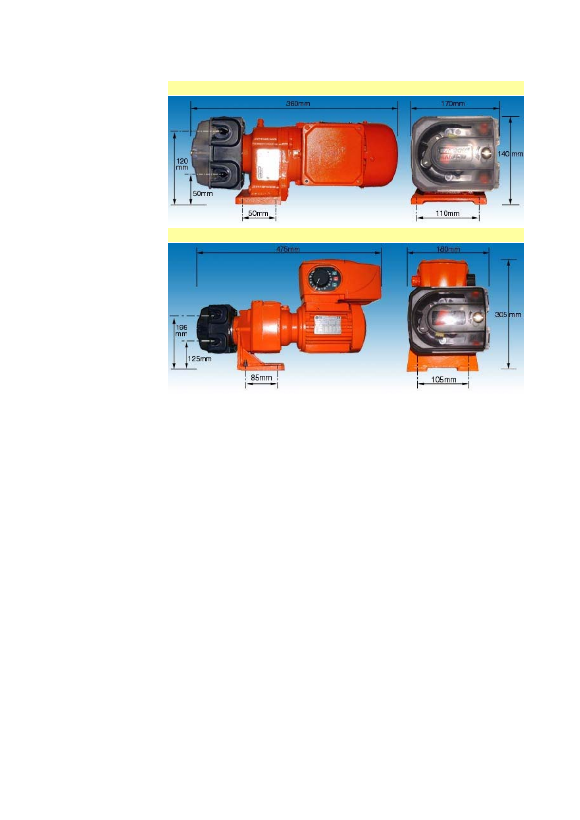
7 Dimensions
521F/RC, 521F/R2C, 521DF/RLA, 521DF/RL2A
521VI/RC, 521VI/R2C
Page 6 of 47Watson-Marlow Bredel E-Manuals
14/12/2009file://M:\staging\pdfs-global\m-521-cc-gb-03.htm
Page 7
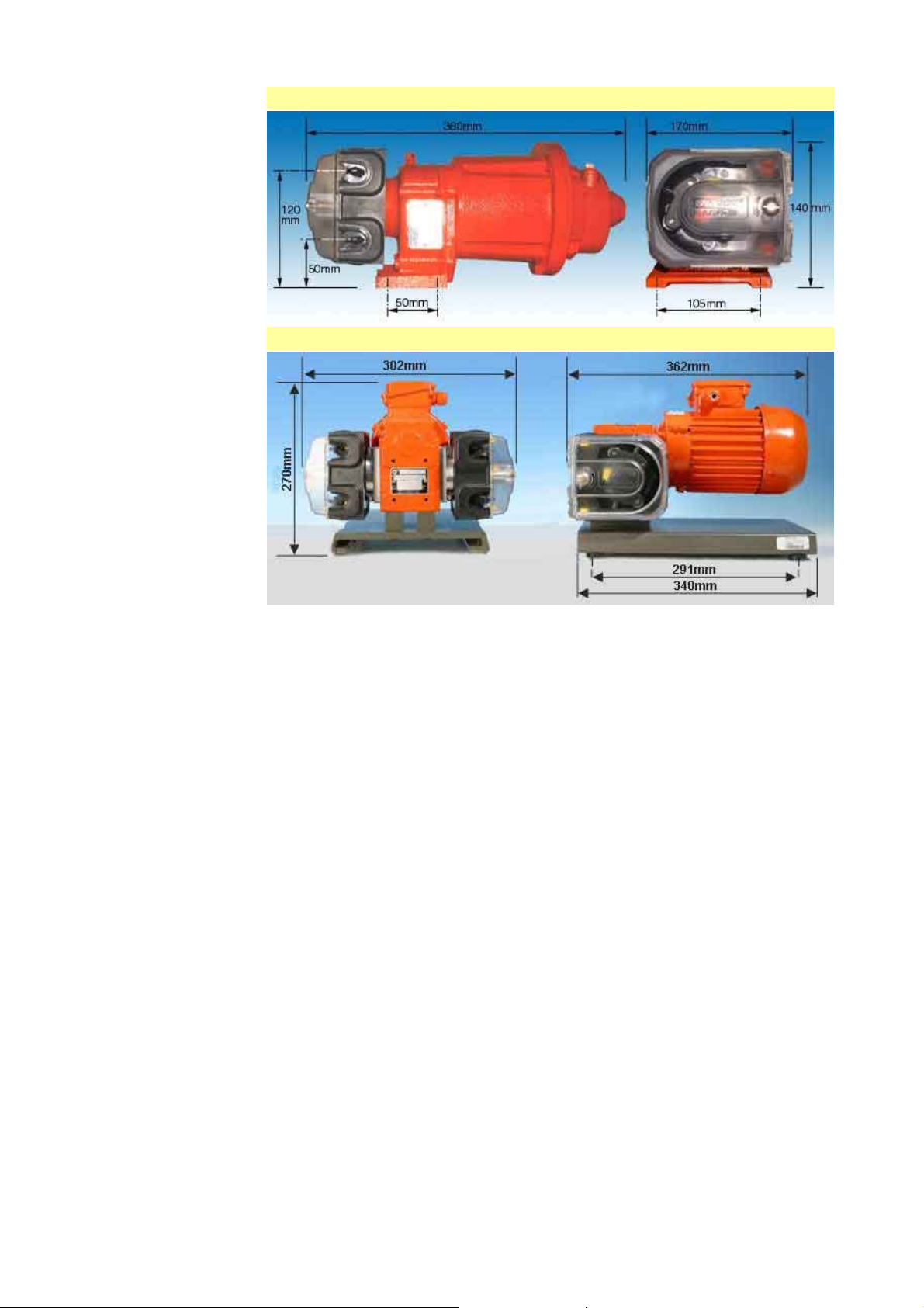
521P/RC, 521P/R2C
521DFX/RLA, 521DFX/RL2A
Page 7 of 47Watson-Marlow Bredel E-Manuals
Note: The pumphead fitted to the 521DFX is the 501RLA, not he 520RC as shown here.
14/12/2009file://M:\staging\pdfs-global\m-521-cc-gb-03.htm
Page 8
Page 8 of 47Watson-Marlow Bredel E-Manuals
8 Unit installation
Site the pump on a flat, horizontal, vibration-proof surface. allowing a free flow of air
around it. Ensure that there is 1m of straight, flexible tubing before the pumphead inlet and
after the pumphead outlet. Close-coupled simplex pumps must be bolted down with four M8
bolts through the gearbox foot mounting holes. The pumphead will need to be removed
before locating the bolts. See section 17: 520RC and 520R2C maintenance.
Duplex pumps are baseplate-mounted as standard.
The pump may be set up so that the direction of rotor rotation is clockwise or ant iclockwise, whichever is convenient. Please note, however, that tube life will be greater if
the rotor rotates clockwise; and that performance against pressure will be maximised if the
rotor rotates anti-clockwise.
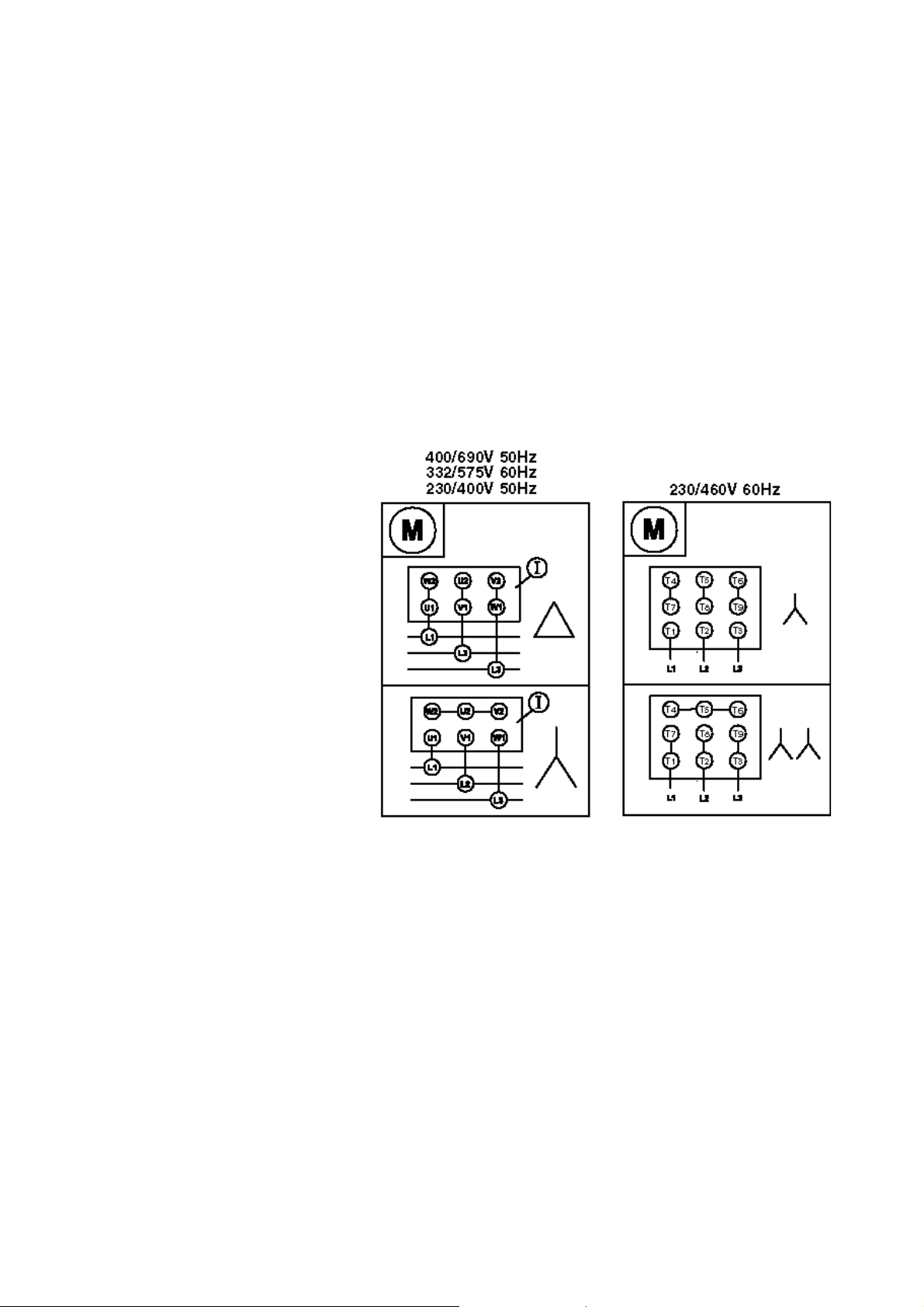
9 Standard AC three-phase motors (integrated)
9.1 AC (IEC) three-phase motors: motor wiring
For Nema C face motors or other options follow manufacturers' guidelines.
Ensure that
the mains
voltage and
frequency
are in
accordance
with the
motor
nameplate
information.
Secure
protective
conductor
connections.
If the motor
runs in the
wrong
direction for
your needs,
interchange
any two
phases.
Close the terminal box and unused cable entrance holes in a dust-tight and watertight
manner, ensuring that the IP55 protection is maintained.
A current overload relay should be fitted to a contact-breaker appropri ate to the current
rating of the motor. Connect the motor in a ccordance with the wiring diagram in the
motor terminal box.
When a thermal protection switch is fitted in the motor, the le ads will be found in the
motor terminal box. They should be connected to open the circuit and stop the pump if
an over-temperature condition occurs.
14/12/2009file://M:\staging\pdfs-global\m-521-cc-gb-03.htm
Page 9
Page 9 of 47Watson-Marlow Bredel E-Manuals
See the drawing below for drive motor connections, showing possible ancillary switches
and connections.
The ancillary switches should be rated to 220/240V 1ph 50Hz/60Hz. The Start contact
should have a sprung return which will disengage following energisation of coils C1 and
C1/1.
Ensure that an emergency stop switch is fitted within reach of the pump.
Do not under any circumstances wire switches directly across any of the
phases of a three-phase supply. If in doubt disconnect the pump
immediately.
Do not connect ancillary switches to the terminal box of a flame-proof
motor unless the switch has a suitable hazardous-atmosphere rating for
the area in which it is to be mounted.
AC three-phase motors must be connected to a suitable earth
terminal. It is imperative that the equipment is powered via an
isolating device and a circuit-breaking device (power contactor)
which can be controlled by an external safety system (emergency
stop, fault detector).
Correct installation and use of an AC three-phase motor with a suitably
rated frequency inverter is the responsibility of the user and should be
carried out by qualified personne l o n ly .
14/12/2009file://M:\staging\pdfs-global\m-521-cc-gb-03.htm
Page 10

Page 10 of 47Watson-Marlow Bredel E-Manuals
9.2 AC three-phase motors: troubleshooting
If the pump will not start make the following checks to determine whether servicing is
required:
Check that mains power is available to the pump.
Check that the motor is connected in the correct Star/Delta configuration.
Check that the pump is not stalled by incorrect fitting of tubing.
Always check to ensure that a hazardous atmosphere motor gearbox is
suitably rated for the hazardous zone area in which it is to be mounted.
Hazardous atmosphere moto r s sh ould be installed only by qualifie d
personnel.
Any deviation from normal operating conditions (increased power
consumption, temperature, vibrations, noise) or warning signals by
monitoring equipment suggest malfunction. Inform the responsible
maintenance personnel at once. If in doubt disconnect the pump
immediately.
9.3 AC three-phase motors: maintenance
Thoroughly clean and regrease the motor assembly every 10,000 working hours or after
two years at the latest.
Remove any dust deposits from the fan cover to avoid overheating.
Dismount anti-friction bearings for cleaning and refill with a grease such as BP
Energrease LS 2 or Mobil Mobilux 2.
Ensure that the bearing cage is packed about 1/3 full with an evenly distributed
lubricating grease such as BP Energrease LS 2 or Mobil Mobilux 2.
9.4 AC three-phase motors: gearbox maintenance simplex (single pumphead) units
Combine a lubricant change with a thorough cleaning of the gear unit every 10,000
working hours or after two years at the latest.
Extreme working conditions (high air humidity, aggressive media and large temperature
variations) will reduce the interval between lubricant changes.
The first oil change should be carried out after approximately 1,000 working hours to
compensate for run-in abrasion. Examples of suitable lubricating oils are BP Energol GRXP 220 and Mobil Mobilgear 630.
9.5 AC three-phase motors: gearbox maintenance duplex (twin pumphead) units
The gearbox is filled for life with synthetic lubricant so no maintenance is required.
14/12/2009file://M:\staging\pdfs-global\m-521-cc-gb-03.htm
Page 11

Page 11 of 47Watson-Marlow Bredel E-Manuals
9.6 AC three-phase motors: gearbox maintenance pump specifications
Control range See motor nameplate
Voltage/frequency See motor nameplate
Power consumption See motor nameplate
Full load current See motor nameplate
Operating temperature range 5C to 40C, 41F to 104F
Storage temperature range -40C to 70C, -40F to 158F
Noise <70dB(A) at 1m
Standards BS EN60529 (IP55)
Machinery directive 2006/42/EC
EMC directive 2004/108/EC
14/12/2009file://M:\staging\pdfs-global\m-521-cc-gb-03.htm
Page 12

Page 12 of 47Watson-Marlow Bredel E-Manuals
10 Varmeca drives
The Varmeca drive is an IP65 integrated electronically-variable speed drive fitted to a
standard enclosure IP55 motor gearbox. Standard Varmeca drives are single-phase but
three-phase Varmecas are available.
Standard Varmeca drives are set up for manual control with the run command enabled.
Current will be applied directly to the motor as soon as mains power is switched on.
Subsequently, speed, direction of rotation and stop control can be achieved from the control
knob and keypad.
For information on how to set up the Varmeca for remote control, please refer to
the Leroy Somer Varmeca-30 manual.
This Varmeca-30 must be connected to an approved earth terminal.
It is imperative that the equipment is powered via an isolating
device and a circuit-breaking device (power contactor) which can
be controlled by an external safety system (emergency stop, fault
detector).
The Varmeca-30 is fitted with safety devices which stop the motor in the event of a fault.
The motor can become jammed for mechanical reasons. Voltage fluctuations and power
cuts may also stop the motor.
Removing the cause of a shutdown can lead to restarting, which may be dangerous for
certain installations. It is essential that the user guards against the motor restarting after
shutdown, if this is undesirable.
10.1 Varmeca drives: installation
The standard Varmeca integrated drive requires no connection other than to the mains
power supply.
The Varmeca motor fan cools the whole unit. Make sure that the ventilation air inlet is
free of obstruction.
It is the responsibility of the owner or user to ensure that the installation, operation and
maintenance of the inverter complies with he alth and safety regulations of the relevant
country of use.
Before carrying out any work, disconnect and lock the drive power
supply. For single phase units, wait two minutes to make sure that
the capacitors have fully discharged. After connection work, make
sure that the seals are firmly in place, and the screws and cable
glands are watertight to ensure IP65 protection. Clear any
condensation from the drain holes at the bottom of the motor.
10.2 Varmeca drives: connections
The voltages on the power terminal blocks and the cables connected to them may cause
fatal electric shocks. The drive stop function does not protect against these high
voltages.
The drive power supply must be protected against overloads and short circuits.
It is vital to respect the rating of protection devices.
Connections should be made with copper conductors only.
14/12/2009file://M:\staging\pdfs-global\m-521-cc-gb-03.htm
Page 13

Page 13 of 47Watson-Marlow Bredel E-Manuals
10.3 Varmeca drives: cables and protection devices
Circuit breakers must be of the D-curve type suitable for a motor with an inverter.
Comply with the size of protection (gl) fuses given in the table below.
The cable size may vary according to legislation applicable in the country of use, which
will take precedence over the values given in the table below without exception.
Power VMA
230V/1/50/60Hz
110V/1/50/60Hz
0.25kW
1/3HP
0.25kW
1/3HP
rating
A or B
21M-025
A or B
21M-025
Current
(A)
gl fuses or circuit
breaker (A)
3.5 8 1.5
6.8 16 2.5
Cable
(sq mm)
NB: The mains current value is a typical value which depends upon the source impedance.
The higher the impedance, the lower the current. The fuses (UL approved) are intended for
installations capable of delivering 5,000A maximum at 480V.
10.4 Varmeca drives: commissioning / start-up
Remove the cover and connect a suitably rated mains cable via the cable gland to
connection points L1, L2 and PE (earth) of the Varmec a terminal block.
Secure the connection cover and cable gland into position, ensuring that the IP65 sealing
is not compromised.
The Varmeca must not be switched on with the connection cover
removed.
The motor Run command has been enabled: the motor will start as
soon as it is switched on.
Power-up at the mains: the green indicator lamp lights and remains on continuously.
Start rotation by pressing a direction button for one second.
Set the speed reference using the side control knob, adjusting speed between 10Hz and
80Hz. The speed control knob is calibrated in percentages of maximum speed.
Press the Stop button to stop the unit.
Varmeca drives fitted with electrical interlock pumpheads
Commissioning / start-up: as standard Varmeca units.
If the guard switch is activated:
Press the Stop button twice to reset the unit after the pumphead guard has been closed
Re-start rotation by pressing a direction button for one second
14/12/2009file://M:\staging\pdfs-global\m-521-cc-gb-03.htm
Page 14
Page 14 of 47Watson-Marlow Bredel E-Manuals
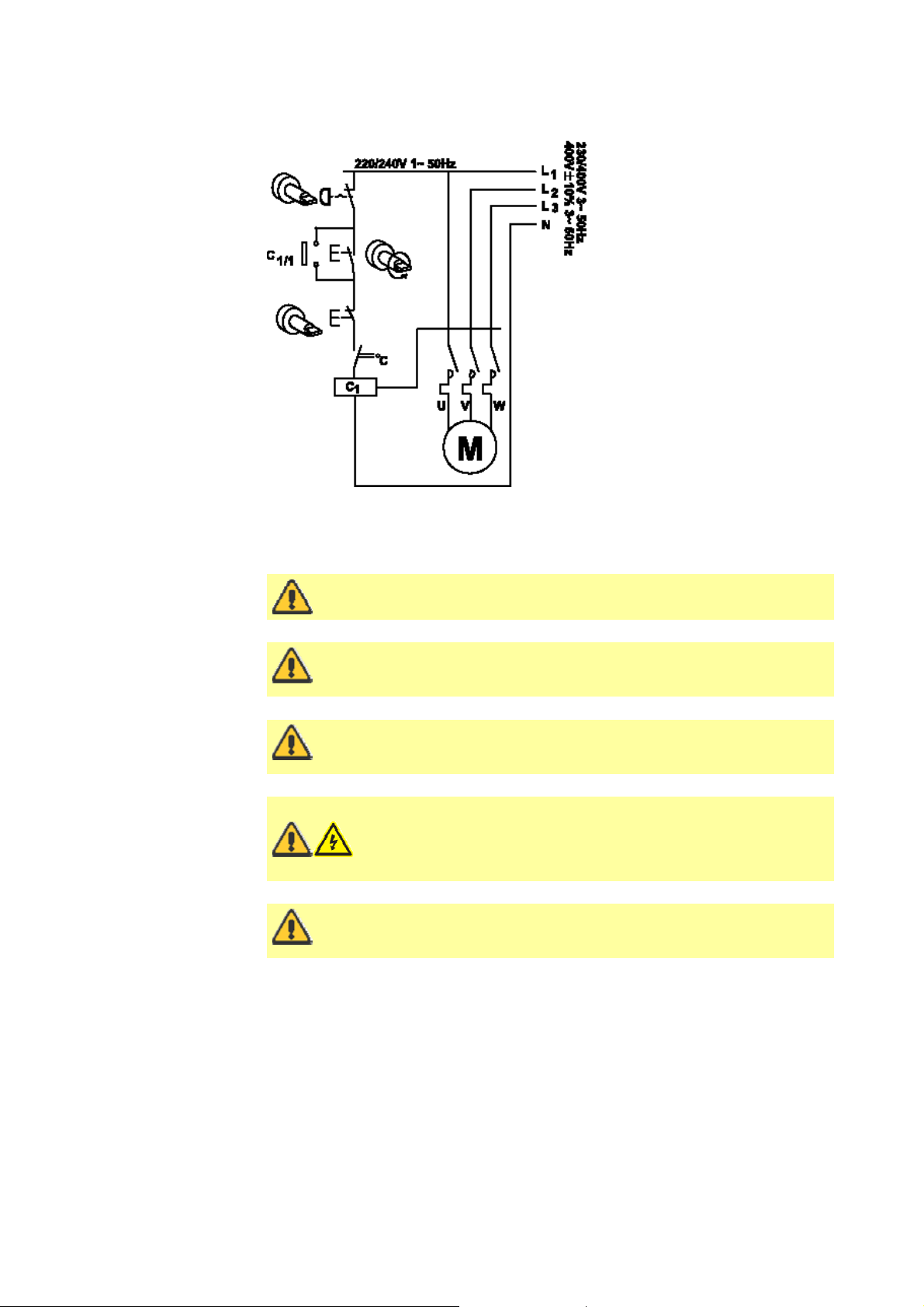
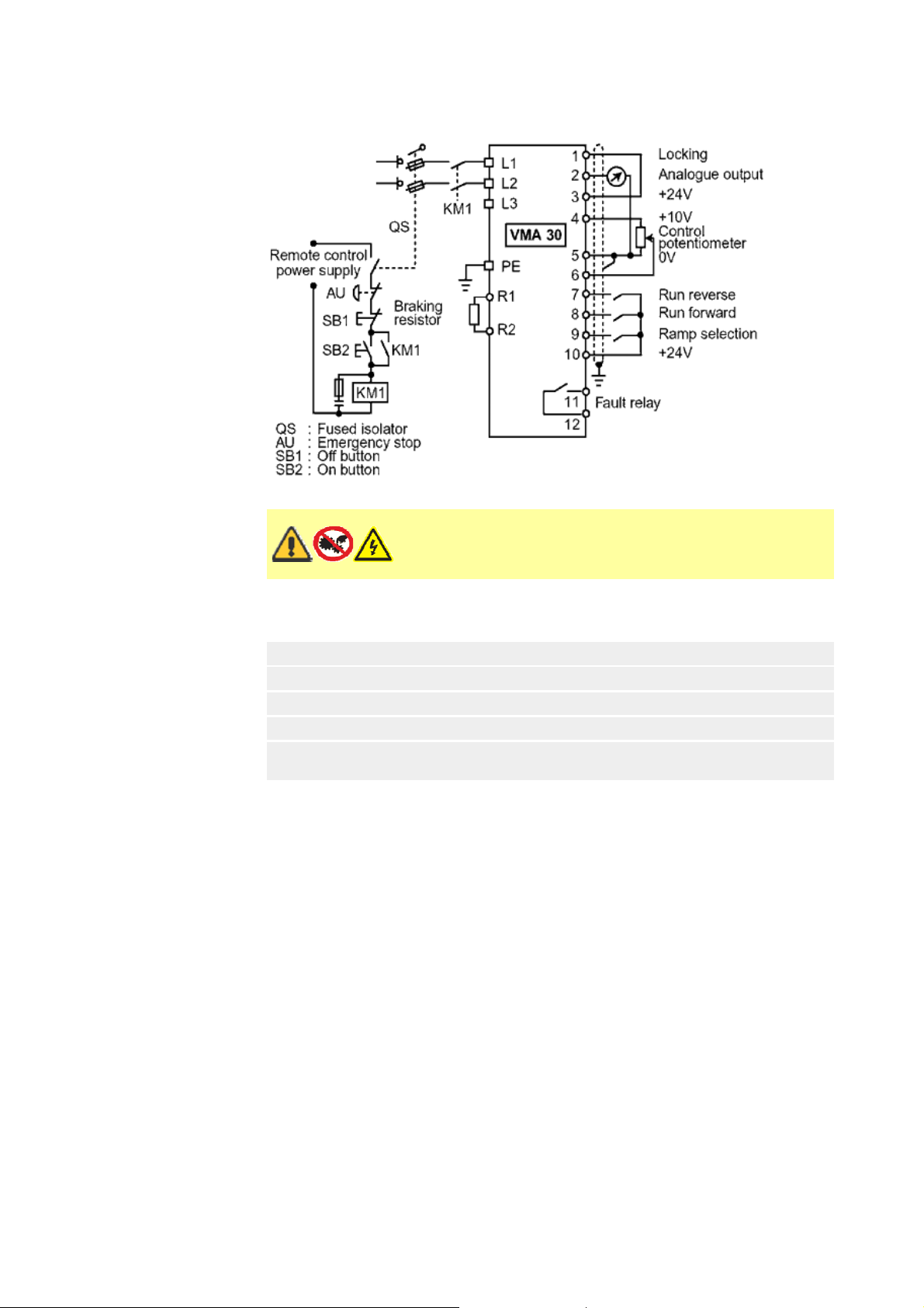
10.5 Varmeca drives: single phase connection diagram
Before switching on the Varmeca-30 motor, check that
electrical connections are correct and that any moving parts
are mechanically protected. The Varmeca-30 must not be
switched on with the protective cover removed.
10.6 Varmeca drives: keypad indicator light display
Steady green light
Flashing green light
Flashing green and red lights
Flashing red light
Steady red light
Fault: under/over voltage
Fault: short circuit; locked motor rotor; faulty winding
insulation; I²t overheating; or internal fault
Mains connected
Motor current overload
Motor current limit
14/12/2009file://M:\staging\pdfs-global\m-521-cc-gb-03.htm
Page 15

Page 15 of 47Watson-Marlow Bredel E-Manuals
10.7 Varmeca drives: Varmeca-30 specifications
Power supply Single phase, 208V -10% to 240V +10%, 50/60Hz
110V -10% to 120V +10%, 50/60Hz ±2%
Power range 0.25kW, 1/3HP
Maximum hourly mains
stop/starts
Overload 150% of nominal current for 60 seconds, 10 times
Efficiency 97.5% motor efficiency
Filter type Class B EMC filter (domestic and light industrial level)
Motor frequency variation range 10Hz-80Hz at constant torque
Enclosure IP65: Varmeca drive; IP55: motor
Storage temperature -40C to +70C (IEC 68.2.1), -40F to 158F
Operating temperature -20C to 50C, -4F to 122F; power derated by 1% per
degree C above 40C, 1% per 1.8 degrees F above
Altitude Up to 1000m without derating
UL standard Conforming to UL508c (E211799)
Weight 21kg, 46lb
±2%
10
per hour
104F
14/12/2009file://M:\staging\pdfs-global\m-521-cc-gb-03.htm
Page 16

T
Page 16 of 47Watson-Marlow Bredel E-Manuals
10.8 Varmeca inverter factory settings
The Watson-Marlow 521VI/RC and 521VI/R2C inverter default settings are listed in the
table below. For more information on each parameter and its options, consult the LeroySomer Varmeca-30 operating instructions.
Parameter Set
P01 F MIN 8 8Hz
P02 REF 0V -
4mA
P03 F MAX 80 80Hz
P04 REF 10V -
20mA
P05 ACCEL 3 3s
P06 DECEL 3 3s
P07 STOP
MODE
P08 Un MOT 400V 400V
P09 FN MOT 50Hz 50Hz
P10 U / F C C: 0.25-1.1kW;
P11 BOOST 8% Adapted to
P12
OVERBOOST
P13 F PWM 11 11: 0.25-2.2kW;
P14 CONFIG Standard
value
8 8Hz
80 80Hz
RAMP RAMP
20% Adapted to
Possible
settings
D: 1.5-7.5kW
motor according
to power
motor according
to power
8: 3-4kW
Standard
Parameter Set
P15 VP1-1 50Hz
P16 VP2-1
VP1-2
P17 VP2 40Hz
P18 VP3-2 70Hz
P19
ROTATION
P20 SELECT
3
P21 PI K PRO 10
P22 PI K INT 10
P23 F MOT P24 I MOT P25 FAULT 0
P26 STOP F
min
P27 LOG
CDC-VMA
P28 CAL MOT 21M
value
60Hz
FORWARD FORWARD
OUTPUT N
0
-
025:520
Possible
settings
Adapted
according to
motor power
10.9 Varmeca care and maintenance
emperature variations and excessive humidity encourage the formation of condensation.
If this occurs, the condensation drain plugs at the bottom of the motor should be
removed, even in a very humid atmosphere.
No specific servicing is required for Varmeca-30 motors, apart from regularly removing
dust from the fan grille and the cooling fins at the bottom of the unit.
Dismantling the Varmeca-30 while it is under warranty will invalidate the warranty.
14/12/2009file://M:\staging\pdfs-global\m-521-cc-gb-03.htm
Page 17

Page 17 of 47Watson-Marlow Bredel E-Manuals
11 Air motors
The air motor is designed for air only. Do not allow corrosive,
flammable or explosive gases or particulate material to enter the
motor. Water vapour, oil-based contaminants or other liquids must
be filtered out. The recommended air pressure should not exceed
7bar (100 psig) maximum.
Always disconnect the air supply before servicing.
11.1 Air motors: installation
The air motor is supplied with a silencer installed. The silencer incorporates a speed limiter.
Install a moisture trap and filter in the air line ahead of the motor. If condensates need to
be flushed out of the motor, use clean, dry air at low pressure. For efficiency of output and
speed control, use air lines of the same size or next pipe size larger than the intake port of
the motor.
A four-way valve which can be connected by piping to both air ports of the motor will make
reversing possible. Use a pressure regulator or a simple shut-off valve to obtain the desired
power and conserve air to regulate speed and torque. The motor should be regulated to
run at no more than 3000rpm.
The air motor should be mounted on a solid baseplate, preferably of metal, which in turn
should be anchored to a shelf, floor or other machinery.
11.2 Air motors: lubrication
Use a detergent SAE#10 automotive engine oil. Lubrication is necessary for all moving
parts and rust prevention. We recommend that an automatic air lubricator be installed in
the air line just ahead of the motor.
Automatic lubrication: An in-line oiler should be adjusted to feed one drop per minute for
high speed or continuous duty use. Do not overfeed oil. Contamination of the exhaust air
may occur.
Manual lubrication: Shut the pump down after every eight hours of operation, and add
10-20 drops of oil through the inlet port.
14/12/2009file://M:\staging\pdfs-global\m-521-cc-gb-03.htm
Page 18

Page 18 of 47Watson-Marlow Bredel E-Manuals
11.3 Air motors: operation
Do not drive an air motor with flammable or explosive gases nor operate
the unit in an atmosphere containing them. Solid or liquid material
leaving the motor can cause eye or ski n da ma ge . Ke ep away from the air
stream. Do not drive an air motor in excess of the recommended speed,
which is governed by a limiter on the outlet port. Do not allow an air
motor to run at high speed with no load: excessive internal heat build-up,
loss of internal clearances and rapid motor damage will result.
11.4 Air motors: starting
Starting torque is less than running torque. It could vary depending on where the vanes
stop in relation to the air intake port. To regulate speed and torque, use a pressure
regulator or simple shut-off valve to obtain desired power and conserve air.
11.5 Air motors: shutdown procedure
Turn off the air supply and remove the air lines from the motor.
Use clean, dry air at low pressure to flush out condensates such as water.
Re-lubricate the air motor with a squirt of oil in the chamber. Rotate the shaft by hand
several times.
Plug or cap each port.
11.6 Air motors: Air motor specifications
Maximum
speed
3,000rpm 7.0bar,
Maximum
pressure
100psig
Maximum
torque
26Nm,
19.2 lb-ft
Maximum air
consumption
14.15 l/s, 30cfm 0.0635mm,
Total internal
end clearance
0.0025in
Total top
clearance
0.0381mm,
0.0015in
11.7 Air motors: troubleshooting
Reason Low
Dirt, foreign material
Internal rust
Misalignment
Insufficient air
pressure
Air line too small
Restricted exhaust
Poor lubrication
Jammed machine
Compressor too small
Compressor too far
from unit
torque
Low
speed
Won't
run
Runs
hot
Runs well then
slows down
14/12/2009file://M:\staging\pdfs-global\m-521-cc-gb-03.htm
Page 19

Page 19 of 47Watson-Marlow Bredel E-Manuals
12 520RC, 520R2C and 520REC pumpheads
Identification of parts
1 Guard latch 5 Rotor cap 9 Pumping roller
2 Guard (520RC, 520R2C) 6 Tube guide roller 10 Tube clamp slider (520RC, 520R2C)
3 Track 7 Rotor 11 Tube clamp (520RC, 520R2C)
4 Clutch button cover 8 Follower roller 12 Guard with seal (520REC)
13
Drain port (520REC)
12.1 520RC, 520R2C and 520REC key safety information
Before opening the pumphead guard, ensure that the following
safety directions are followed.
For close-coupled drives, ensure that the pump is isolated fr om the mains voltage.
Ensure that there is no pressure in the pipeline.
Primary operator protection from rotating parts of the pump is provided by the tool-
unlockable safeguard.
Secondary (backup) protection is available in the form of an electrical interlock which
stops the pump if the pumphead guard is opened (and only for so long as the guard is
opened). The electrical interlock on close-coupled pumps should never be used as
primary protection. Always disconnect the mains power supply to the pump before
opening the pumphead guard.
If a tube failure has occurred, ensure that any fluid in the pumphead has been allowed to
drain to a suitable vessel, container or drain.
Ensure that protective clothing and eye protection are worn if hazardous fluids are being
pumped.
14/12/2009file://M:\staging\pdfs-global\m-521-cc-gb-03.htm
Page 20

Page 20 of 47Watson-Marlow Bredel E-Manuals
12.2 520RC, 520R2C and 520REC: good pump installation
practice
General recommendations
The pump may be set up so that the direction of rotor rotation is clockwise or counterclockwise, whichever is convenient. Please note, however, that for the 520R and 501RL
pumpheads tube life will be greater if the rotor rotates clockwise; and that performance
against pressure will be maximised if the rotor rotates counter-clockwise. To achieve 4 bar
and 7 bar pressures using a 520RE pump and the appropriate rotor and element, the pump
must rotate counter-clockwise.
Peristaltic pumps are self-priming and self-sealing against backflow. No valves are required
in inlet or discharge lines, except as described below. Valves in the process flow must be
opened before the pump operates. Users are advised to fit a pressure relief device between
the pump and any valve on the discharge side of the pump to protect against damage
caused by accidental operation with the discharge valve closed. Users of 520RE pumps at
pressures up to 4 bar and 7 bar are advised to fit a non-return valve between the pump and
the discharge pipework to avoid the sudden release of pressurised fluid in the unlikely event
of element failure.
Do keep delivery and suction tubes as short and direct as possible - though ideally not
shorter than 1m - and follow the straightest route. Use bends of large radius: at least four
times the tubing diameter. Any valves in the pipeline (not usually needed with a selfpriming peristaltic pump) must not restrict the flow.
Do use suction and delivery pipes equal to or larger than the bore of the tube in the
pumphead. When pumping viscous fluids use pipe runs with a bore several times larger
than the pump tube.
Do site the pump at or just below the level of the fluid to be pumped if possible. This will
ensure flooded suction and maximum pumping efficiency.
Do keep the pumphead track and all moving rollers clean and free from debris.
When using Marprene or Bioprene tubing, re-tension the tube after the first 30 minutes
of running.
Tube selection: The chemical compatibility list published in the Watson-Marlow catalogue
is only a guide. If in doubt about the compatibility of a tube material and the duty fluid,
request a Watson-Marlow tube sample card for immersion trials.
A correctly engineered installation will promote long tube life. Please ensure that these
guidelines are followed:
Avoid tight pipeline bends, pipe reducers and lengths of smaller bore tubing than the
pumphead section, particularly in pipelines on the suction side.
Ensure that at least 1m of smooth bore flexible tubing is connected to the discharge port
of the pumphead to help to minimise impulse losses and pulsation in the pipeline. This is
specially important with viscous fluids and when connecting to rigid pipework.
Ensure that connecting pipework and fittings are suitably rated to handle the predicted
pipeline pressure. If rigid pipework must be used close to the pumphead, a drop-out
section of pipe will simplify tube replacement.
14/12/2009file://M:\staging\pdfs-global\m-521-cc-gb-03.htm
Page 21

Page 21 of 47Watson-Marlow Bredel E-Manuals
12.3 520RC, 520R2C and 520REC: pumphead position,
removal and replacement
The pumphead track can be fitted in one of two orientations to provide left or right
input/output port positions, and clockwise or anti-clockwise rotor rotation, whichever is
convenient. Please note, however, that tube life will be greater if the rotor rotates
clockwise; and that performance against pressure will be maximised if the rotor rotates
anti-clockwise.
To reposition the track
Isolate the pump from the mains power supply.
Open the pumphead guard as described under Opening the pumphead guard, below.
Remove the rotor as described under Rotor removal.
Undo and withdraw the four track-retaining screws using a slotted screwdriver.
Remove the track.
Relocate the track in the desired position. Replace and tighten the track-retaining screws.
Replace the rotor as described under Rotor replacement below.
Close the guard, pushing it fully home until the latch engages.
14/12/2009file://M:\staging\pdfs-global\m-521-cc-gb-03.htm
Page 22

Rotor removal
Remove any tubing from the pumphead.
Open the flexible rotor cap in the centre of the rotor.
Undo and withdraw the central locating screw using a slotted screwdriver.
Pull the rotor hub off its dogged shaft.
Between the hub and the shaft is a split collet. If the collet
is retained by the shaft, pull it off, loosening it if necessary
by tapping it lightly. Avoid levering it off using a
screwdriver or other tool. If the collet is retained within
the hub, remove it, loosening it if necessary by reinserting
the central locating screw a turn or two and tapping the
screw head lightly.
Page 22 of 47Watson-Marlow Bredel E-Manuals
Rotor replacement
Re-locate the split collet onto the drive shaft, rotating it until it fully engages the dog. Fit
the rotor body over the drive shaft as one unit.
Open the flexible rotor cap in the centre of the rotor. Use a slotted screwdriver to tighten
the central locating screw to a torque of 3Nm (2.2 lb-ft) to prevent collet slip during
operation. When fitted correctly, the tube guid e rollers should align with the outer face of
the track. Close the flexible rotor cap.
Close the guard and ensure that the rotor is clear of t he guard by observing the first few
rotor rotations.
14/12/2009file://M:\staging\pdfs-global\m-521-cc-gb-03.htm
Page 23

Page 23 of 47Watson-Marlow Bredel E-Manuals
13 520RC, 520R2C and 520REC installation
13.1 Opening the pumphead guard
Isolate the pump from the mains power supply.
Unlock the pumphead guard by turning the guard fastener ¼ turn anticlockwise with a
flat-head screwdriver.
Open the guard to its full extent to create maximum clearance for the tube ports.
Ensure that the rollers rotate freely and that the tube clamps are clean.
13.2 520RC and 520R2C tube loading
520RC continuous tubing pumpheads are factory-set to accept Watson-Marlow 1.6mm-wall
tubing. 520R2C continuous tubing pumpheads for close-coupled drives are factory set to
accept Watson-Marlow 2.4mm-wall tubing. Pumping performance may be adversely
affected if Watson-Marlow tubing is not used.
Mark a 225mm length onto the section of the tubing which is to be located into the
pumphead.
Open the lower spring-loaded tube clamp and locate tubing, with the first 225mm length
mark aligned to the inside face of the spring-loaded part of the tube clamp. Release the
clamp.
Disengage the rotor clutch by fully depressing the yellow clutch button on the side of the
rotor hub and turning the hub a few degrees while the clutch button is still depressed.
The rotor can now rotate independently of the gearbox and motor for one full revolution.
If the clutch re-engages before tube fitting is complete, depress the clutch button again
and turn the rotor a few degrees.
14/12/2009file://M:\staging\pdfs-global\m-521-cc-gb-03.htm
Page 24

Page 24 of 47Watson-Marlow Bredel E-Manuals
Feed the tubing around the pumphead track, turning the rotor as necessary. Make sure
the tubing is not twisted. Ensure that the second 225mm mark is adjacent to the inner
edge of the upper tube clamp.
Open the upper spring-loaded tube clamp and locate the tubing into it, making sure ther e
is no residual twist in the tubing, and that the tube sits centrally between the tube guide
rollers. Release the clamp.
The spring-loaded tube clamps must grip the tubing tightly enough to stop it moving in
and out of the pumphead but must not over-squeeze the tube and throttle fluid flow. The
tubing clamps are fitted with yellow sliders which can be clicked into two positions while
the clamps are held open: the outer position will allow the clamps to grip the tube
tightly; the inner will grip the tube loosely. Adjust the sliders to prevent tube movement
during a few trial rotations of the rotor.
Close the guard, pushing it fully home until the latch engages.
Connect suitable pipework to the pumphead tubing using appropriate connectors.
Remember, when using Marprene or Bioprene tubing, re-tension the tubing after 30
minutes of running, as it may grow in length as it beds in. Re-tension so that 225mm of
tubing sits between the inside faces of the spring-loaded parts of the tube clamps.
14/12/2009file://M:\staging\pdfs-global\m-521-cc-gb-03.htm
Page 25

Page 25 of 47Watson-Marlow Bredel E-Manuals
13.3 520REC: fitting the drain port
The drain port is an optional extra, supplied with the pumphead. It is strongly
recommended that users fit it before the pump is operated. This may be done with the rotor
in position or removed.
Remove the drain plug from the bottom of the pumphead. The drain plug is flexible. It
may be removed using finger pressure from within the pumphead, or by accessing its
flange from outside with a fingernail.
Drop the port into position from inside the pumphead.
Fit the supplied port retaining nut (3/8in BSP) and finger-tighten.
Fit drainage pipework as required (not supplied).
14/12/2009file://M:\staging\pdfs-global\m-521-cc-gb-03.htm
Page 26

Page 26 of 47Watson-Marlow Bredel E-Manuals
13.4 520REC element loading
520RE tubing element pumpheads are factory-set to accept Watson-Marlow 2.4mm-wall
tubing elements. Elements fitted with either quick-release industrial connectors or Tri-clamp
sanitary connectors may be used; however, it is vital to match the pressure rating of
the element with the pressure rating of the pumphead so that the correct rollerspringing and occlusion settings are used. The pressure rating of the pumphead appears on
the flexible rotor cap in the centre of the rotor. The pressure rating of the element appears
on the connector sleeve.
Note that the rotor cap and the element connector sleeve are colour-coded.
Note: To achieve 4 bar and 7 bar pressures using a 520RE pump and th e appropriate rotor
and element, the pump must rotate counter-clockwise.
Element and rotor pressure ratings
Colour of flexible rotor cap and element connector sleeve
Grey Beige Blue
520REL
Pressures
up to 2 bar (30 psi)
3.2mm, 6.4mm and 9.6mm
Industrial
Marprene TL
Bore sizes
Sanitary
Bioprene TL
Pumpsil
Neoprene
ChemSure
Element connectors for industrial and sanitary use
Industrial Sanitary
Check that the conical connector sleeve of the element to be fitted is the
same colour as the pumphead rotor cap
Pumpsil
Sta-Pure
ChemSure
Industrial
Marprene TM
ChemSure
520REM
Pressures
up to 4 bar (60 psi)
Bore sizes
3.2mm and 6.4mm
Sanitary
Bioprene TM
Sta-Pure
520REH
Pressures
up to 7 bar (100 psi)
Bore size
3.2mm
Industrial
Marprene TH
Sta-Pure
Sanitary
Bioprene TH
Sta-Pure
14/12/2009file://M:\staging\pdfs-global\m-521-cc-gb-03.htm
Page 27

Page 27 of 47Watson-Marlow Bredel E-Manuals
520REC element loading procedure
Note: The element loading procedure is the same for industrial (pictured) and sanitary
elements.
Select an appropriate Watson-Marlow 520RE tubing element, paying attention to
pressure capability, bore size, tubing material and type of connector. See the table above
for pressure ratings. Check that the connector sleeve of the element to be fitted is
the same colour as the pumphead rotor cap.
Slide the connector D-flange at one end of the element into the lower connector D-slot.
Disengage the rotor clutch by fully depressing the yellow clutch button on the side of the
rotor hub and turning the hub a few degrees while the clutch button is still depressed.
The rotor can now rotate independently of the gearbox and motor for one full revolution.
If the clutch re-engages before tube fitting is complete, depress the clutch button again
and turn the rotor a few degrees.
Feed the tubing element around the pumphead track, turning the rotor as necessary.
Make sure the tubing is not twisted or pinched between the guide rollers and the track.
Slide the second connector D-flange into the upper connector D-slot.
Check that the element lies snugly in the middle of the track and that the connectior
flanges are pushed fully home.
Close the guard, pushing it fully home until the latch engages.
Connect suitable pipework to the pumphead tubing using appropriate connectors. See
below.
14/12/2009file://M:\staging\pdfs-global\m-521-cc-gb-03.htm
Page 28

Page 28 of 47Watson-Marlow Bredel E-Manuals
13.5 520REC element connection
Select suitable tubing to connect to the tubing element supply and discharge connectors.
Check that its pressure rating is appropriate to the application.
Sanitary ¾in Tri-clamp connectors
Sanitary connectors are connected to a tubing system using Tri-clamps and EPDM gaskets.
Hold the connector end of the supply or discharge tube against the element connector,
with a gasket between them.
Use a Tri-clamp to engage both flanges squarely, close it and tighten.
Industrial quick-release connectors
Industrial connectors are connected to a tubing system using quick-release fittings.
Hold the pump securely and push the female fitting (available from Watson-Marlow
Bredel) over the element until it clicks into place.
To disconnect, hold the pump securely and pull the connector outer sleeve and twist
counter-clockwise while pulling the female connector away.
14/12/2009file://M:\staging\pdfs-global\m-521-cc-gb-03.htm
Page 29

Page 29 of 47Watson-Marlow Bredel E-Manuals
14 520RC, 520R2C and 520REC maintenance
Always isolate the pump from the mains power supply before opening the
guard or performing any positioning, removal or maintenance activity.
As part of regular cleaning and maintenance (and at least every three months), lubricate
the pivot points, the follower rollers and the tube guide rollers with Ultra Lube (PA 1240),
which is a non-toxic perfluoroether-based grease.
The stainless steel pumping rollers run on externally-sealed bearings and are lubricated
for life.
Check that the pumphead track, rotor, rollers and spring-loaded tube clamps are clean
and operating properly.
If fluid is spilled inside the pumphead it should be cleaned as soon as possible, as
reducing pumphead exposure time to contamination will prolong service life.
To clean the pumphead, remove the rotor as described under Rotor removal, below.
Flush the pumphead out with water and mild detergent, or suitable cleaning agent. Clean
the rotor and rollers in the same way. If specific cleaning agents are required to clean the
spillage, consult the general guide to cleaning with solvents below or Watson-Marlow
technical support office before proceeding, in order to confirm chemical compatibility.
Note: the pumphead guard, rotor cap and clutch boot should be removed in advance of
some cleaning regimes. See the table below. These components are available as spares if
damaged.
Replace the rotor as described above.
General guide to cleaning with solvents
Chemical Cleaning precautions
Aliphatic hydrocarbons Remove guard. Minimise rotor cap and clutch boot exposure
Aromatic hydrocarbons Remove guard. Minimise rotor cap and clutch boot exposure
Ketone solvents Remove guard. Minimise rotor cap and clutch boot exposure
Halogenated/chlorinated
solvents
Alcohols, general No precaution necessary.
Glycols Minimise rotor cap and clutch boot exposure to less than one
Ester solvents Remove guard. Minimise rotor cap and tube clamp location
Ether solvents Not recommended: possible risk to polycarbonate tube
to less than one minute (risk of attack).
Re-lubricate follower and tube guide rollers.
to less than one minute (risk of attack).
Re-lubricate follower and tube guide rollers.
to less than one minute (risk of attack).
Re-lubricate follower and tube guide rollers.
Not recommended: possible risk to polycarbonate tube
clamp adjusters and polypropylene tube clamp locators.
Re-lubricate follower and tube guide rollers.
minute (risk of attack).
Re-lubricate follower and tube guide rollers.
cap exposure to less than one minute (risk of attack).
Re-lubricate follower and tube guide rollers.
clamp adjusters and polypropylene tube clamp locators.
14/12/2009file://M:\staging\pdfs-global\m-521-cc-gb-03.htm
Page 30

Page 30 of 47Watson-Marlow Bredel E-Manuals
15 520RC, 520R2C and 520REC rotor settings
520RC, 520R2C and 520REC pumpheads are factory-set to give optimum tube life with
Watson-Marlow tubing. Radial roller positions should not be adjusted in any circumstances
as this will adversely affect pumphead performance and invalidate warranty. Tamper-proof
rotor arm occlusion setting screws are fitted to warn operators from occlusion adjustment.
Tubing with a wall thickness other than 1.6mm or 2.4mm can be used only with a
pumphead set up for that purpose during manufacture. Contact Watson-Marlow technical
support.
Note: 520RC, 520R2C, and 520REC pumpheads can not be adapted to use tube with walls
thicker than 2.4mm.
14/12/2009file://M:\staging\pdfs-global\m-521-cc-gb-03.htm
Page 31

16 Pumphead spares
520RC/520R2C 520RELC/520REMC/520REHC
Page 31 of 47Watson-Marlow Bredel E-Manuals
1 MNA2050A (520RC, 520R2C)
2 MNA2044A (520RC, 520R2C) Track assembly for close-coupled pumps
3 MNA2076A
(520RC - 1.6mm wall tube)
MNA2077A
(520R2C - 2.4mm wall tube)
MNA2148A (grey) (520RELC)
MNA2149A (beige) (520REMC)
MNA2150A (blue) (520REHC)
4 MN2011M
S60022
5 MNA2043A
(520RC - 1.6mm wall tube)
MNA2001A
(520R2C - 2.4mm wall tube)
MNA2138A
(520RELC - 0-2 bar, 0-30 psi)
MNA2139A
(520REMC - 2-4 bar, 30-60 psi)
MNA2140A
(520REHC - 4-7 bar, 60-100 psi)
6 MNA2006A (520RC, 520R2C)
MN2002M (520RC, 520R2C)
MN2131M (520REC)
7 MNA2005A (520RC, 520R2C)
MN2002M (520RC, 520R2C)
8 MN2034B
MN2005M
9 MNA2147A (520REC) Pumphead guard complete with
10 MNA2145A (520REC) Track assembly for close-coupled pumps
11 MN2023T and MN2003T (520REC) Drain port and nut
Rotor assembly complete with pumping rollers,
complete with tool-unlockable latch
complete with spring-loaded tube clamps
Rotor cover, rotor cap and clutch button
follower rollers and tube guide rollers
Tube clamp location plug
Tube clamp location plug
Guard latch spring cartridge
seal and tool-unlockable latch
Pumphead guard
Clutch
Clutch spring
Bottom (LH) tube clamp
Drain plug
Top (RH) tube clamp
Guard latch spring
Parts may be ordered individually.
14/12/2009file://M:\staging\pdfs-global\m-521-cc-gb-03.htm
Page 32

Page 32 of 47Watson-Marlow Bredel E-Manuals
17 Flow rates
Pumping conditions
For precise and repeatable performance it is important to determine flow rates
under operating conditions for each new piece of tubing.
When rotating counter-clockwise, 520R, 520R2 and 520RE pumpheads' flow rates
are directly proportional to rotor speed. When rotating clockwise, 520R, 520R2
and 520RE pumpheads' flow rates are directly proportional to rotor speed up to
1.5 bar; their performance above 1.5 bar should be determined empirically.
Note: 520RE pumpheads should be used rotating counter-clockwise if pressures
above 1.5 bar are required.
If you wish to run the pump at a speed not shown in the tables below, flow figures
can be reached by dividing the maximum flow shown in the tables below by the
maximum rpm figure, and multiplying the result by your required speed in rpm.
Actual flow rates achieved may vary because of changes in temperature, viscosity, inlet and
discharge pressures, system configuration and tubing performance against time. Flow rates
may also vary due to normal manufacturing tolerances of the tubing. These tolerances will
make flow rate variance more pronounced at smaller bore sizes.
520R and 520R2
All performance figures for the 520R and 520R2 pumpheads have been recorded against
peak pipeline pressures.
Although rated to 2bar (30psi) peak pressure, this pump will generate in excess of 2bar
(30psi) peak pressure if the pipeline is restricted. Where it is important that 2bar (30psi) is
not exceeded, pressure relief valves should be installed in the pipeline.
Viscosity handling is maximised by using 2.4mm wall tubing with the 520R2 pumphead.
Flow rates are normalised test values obtained using 225mm (8 7/8) of new tubing
(measured from the inside faces of the tube clamps), and the pumphead rotating clockwise
pumping water at 20C with negligible inlet and discharge pressures.
Note: Flow rates quoted are for 1.6mm and 2.4mm wall tubes of nominal bore. Tubes of
0.5mm and 0.8mm bore are only available in 1.6mm wall thickness except for platinumcured silicone. Tubes of 9.6mm bore are only available in 2.4mm wall thickness.
520RE
Performance figures for the 520REL and 520REM have been recorded against 2bar peak
pressure and 4bar peak pressure respectively.
Performance figures for the 520REH have been recorded against 7bar constant pressure.
Although the 520REL is rated to 2bar (30psi) peak pressure, the 520REM is rated to 4bar
(60psi) peak pressure and the 520REH is rated to 7bar (100psi) constant pressure the
pumps will generate in excess of these pressures if the system pressures exceed this.
Where it is important that these rated pressures are not exceeded, pressure relief valves
should be installed in the pipeline.
Flow rates are normalised test values obtained using 520 elements and the pumphead
rotating anticlockwise pumping water at 20C with negligible inlet and discharge pressures.
14/12/2009file://M:\staging\pdfs-global\m-521-cc-gb-03.htm
Page 33

Continuous tubing
520RC Neoprene, Sta-Pure, Chem-Sure, PVC, Pumpsil (ml/min)
Speed
range
521F/RC, 521F/R2C
521I/RC, 521I/R2C
6-60rpm
21213rpm
29291rpm
521P/RC, 521P/R2C
26-
257rpm
521VI/RC, 521VI/R2C
6-63rpm
22220rpm
27275rpm
521FX/RC, 521FX/R2C
521DFX/RC, 521DFX/R2C
521IX/RC, 521IX/R2C
6-54rpm
21206rpm
0.5mm 0.8mm 1.6mm 3.2mm 4.8mm 6.4mm 8.0mm 9.6mm
0.26-
2.6
0.9-9.2 2.3-23 9.2-94 37-370 83-840
1.2-132 3.2-32 13-130 51-510
1.1-11 2.9-28 11-110
0.26-
2.7
0.95-
9.5
1.2-12 3.0-30 12-120 48-480
0.26-
2.3
0.9-8.9 2.3-23 9.2-91 37-360 83-820
0.66-
6.6
0.66-
6.9
2.4-24 9.7-97 39-390 87-870
0.66-
5.9
2.6-26 11-110 24-240 42-420 66-660 95-950
1101200
464500
2.6-28 11-110 24-250 42-440 66-690 95-1000
2.6-24 11-95 24-210 42-380 66-590 95-860
1001000
1101100
1501500
2002000
1801800
1501500
1901900
1501500
2302300
3203200
2902800
2402400
3003000
2302300
Page 33 of 47Watson-Marlow Bredel E-Manuals
3303400
4604600
4104100
3503500
4304400
3303300
520RC Marprene / Bioprene 64 shore tubing (ml/min)
Speed
range
521F/RC, 521F/R2C
521I/RC, 521I/R2C
6-60rpm
21213rpm
29291rpm
521P/RC, 521P/R2C
26-
257rpm
521VI/RC, 521VI/R2C
6-63rpm
22220rpm
27275rpm
521FX/RC, 521FX/R2C
521DFX/RC, 521DFX/R2C
521IX/RC, 521IX/R2C
0.5mm 0.8mm 1.6mm 3.2mm 4.8mm 6.4mm 8.0mm 9.6mm
0.25-
2.5
0.86-
8.7
1.2-12 3.0-31 12-120 49-490
1.1-11 2.7-27 11-110 44-430 98-970
0.25-
2.6
0.90-
9.0
1.1-11 2.8-29 11-120 45-460
0.25- 0.63-
0.63-
6.3
2.2-22 8.8-89 35-360 79-810
0.63-
6.6
2.3-23 9.2-92 37-370 83-830
2.5-25 10-100 23-230 40-400 63-630 91-910
1101100
2.5-26 10-110 23-240 40-420 63-660 91-950
1001000
1401400
1902000
1701700
1501500
1801800
2202200
3003100
2702700
2302300
2802900
3203200
4404400
3903900
3303300
4104200
14/12/2009file://M:\staging\pdfs-global\m-521-cc-gb-03.htm
Page 34

Page 34 of 47Watson-Marlow Bredel E-Manuals
6-54rpm
21-
206rpm
2.2 5.7 2.5-23 10-91 23-200 40-360 63-570 91-820
0.86-
8.4
2.2-22 8.8-87 35-350 79-780
1401400
2202200
3203100
14/12/2009file://M:\staging\pdfs-global\m-521-cc-gb-03.htm
Page 35

Page 35 of 47Watson-Marlow Bredel E-Manuals
520RC Fluorel (ml/min)
Speed range 1.6mm 3.2mm 4.8mm 6.4mm 8.0mm
521F/RC, 521F/R2C
521I/RC, 521I/R2C
6-60rpm
21-213rpm
29-291rpm
521P/RC, 521P/R2C
26-257rpm
521VI/RC, 521VI/R2C
6-63rpm 1.9-20 7.7-81 17-180 31-320 48-500
22-220rpm 7.0-70 28-280 63-630 110-1100 180-1800
27-275rpm
521FX/RC, 521FX/R2C
521DFX/RC, 521DFX/R2C
521IX/RC, 521IX/R2C
6-54rpm
21-206rpm
1.9-19 7.7-77 17-170 31-310 48-480
6.7-68 27-270 60-610 110-1100 170-1700
9.3-93 37-370 84-840 150-1500 230-2300
8.3-82 33-330 75-740 130-1300 210-2100
8.6-88 35-350 78-790 140-1400 220-2200
1.9-17 7.7-69 17-160 31-280 48-430
6.7-66 27-260 60-590 110-1100 170-1600
14/12/2009file://M:\staging\pdfs-global\m-521-cc-gb-03.htm
Page 36

520RC Neoprene, Sta-Pure, Chem-Sure, PVC, Pumpsil (USGPH)
Speed
range
521F/RC, 521F/R2C
521DF/RLA, 521DF/RL2A
521P/RC, 521P/R2C
521V/RC, 521V/R2C
5.7-57rpm
22.7227rpm
521VI/RC, 521VI/R2C
6.3-63rpm
22-220rpm
27.5275rpm
521FD/RC, 521FD/R2C
521DFD/RC, 521DFD/R2C
6.5-65rpm
24.7247rpm
0.5mm 0.8mm 1.6mm 3.2mm 4.8mm 6.4mm 8.0mm 9.6mm
0.004-
0.04
0.015-
0.15
0.004-
0.04
0.015-
0.15
0.019-
0.19
0.004-
0.04
0.017-
0.17
0.01-
0.1
0.04-
0.4
0.01-
0.1
0.04-
0.4
0.05-
0.5
0.01-
0.1
0.04-
0.4
0.04-
0.4
0.16-
1.6
0.04-
0.4
0.15-
1.5
0.19-
1.9
0.05-
0.5
0.17-
1.7
0.16-
1.6
0.63-
6.3
0.18-
1.8
0.61-
6.1
0.77-
7.7
0.18-
1.8
0.69-
6.9
0.36-
3.6
1.4-14 2.5-25 4.0-40 5.7-57
0.40-
4.0
1.4-14 2.5-25 3.8-38 5.5-55
1.7-17 3.1-31 4.8-48 6.9-69
0.41-
4.1
1.6-16 2.8-28 4.3-43 6.2-62
0.64-
6.4
0.70-
7.0
0.73-
7.3
Page 36 of 47Watson-Marlow Bredel E-Manuals
0.99-
9.9
1.1-11 1.6-16
1.1-11 1.6-16
1.4-14
14/12/2009file://M:\staging\pdfs-global\m-521-cc-gb-03.htm
Page 37

520RC Marprene / Bioprene 64 shore tubing (USGPH)
Speed
range
521F/RC, 521F/R2C
521DF/RLA, 521DF/RL2A
521P/RC, 521P/R2C
521V/RC, 521V/R2C
5.7-57rpm
22.7227rpm
521VI/RC, 521VI/R2C
6.3-63rpm
22-220rpm
27.5275rpm
521FD/RC, 521FD/R2C
521DFD/RC, 521DFD/R2C
6.5-65rpm
24.7247rpm
0.5mm 0.8mm 1.6mm 3.2mm 4.8mm 6.4mm 8.0mm 9.6mm
0.004-
0.04
0.015-
0.15
0.004-
0.04
0.014-
0.14
0.018-
0.18
0.004-
0.04
0.016-
0.16
0.01-
0.1
0.04-
0.4
0.01-
0.1
0.04-
0.4
0.05-
0.5
0.01-
0.1
0.04-
0.4
0.04-
0.4
0.15-
1.5
0.04-
0.4
0.15-
1.5
0.18-
1.8
0.04-
0.4
0.16-
1.6
0.15-
1.5
0.60-
6.0
0.17-
1.7
0.59-
5.9
0.73-
7.3
0.17-
1.7
0.66-
6.6
0.34-
3.4
1.4-14 2.4-24 3.8-38 5.4-54
0.38-
3.8
1.3-13 2.3-23 3.7-37 5.3-53
1.6-16 2.9-29 4.6-46 6.6-66
0.39-
3.9
1.5-15 2.6-26 4.1-41 5.9-59
0.61-
6.1
0.67-
6.7
0.69-
6.9
Page 37 of 47Watson-Marlow Bredel E-Manuals
0.95-
9.5
1.0-10 1.5-15
1.1-11 1.6-16
1.4-14
14/12/2009file://M:\staging\pdfs-global\m-521-cc-gb-03.htm
Page 38

Page 38 of 47Watson-Marlow Bredel E-Manuals
520RC Fluorel (USGPH)
Speed range 1.6mm 3.2mm 4.8mm 6.4mm 8.0mm
521F/RC, 521F/R2C
521DF/RLA, 521DF/RL2A
521P/RC, 521P/R2C
521V/RC, 521V/R2C
5.7-57rpm
22.7-227rpm
521VI/RC, 521VI/R2C
6.3-63rpm
22-220rpm
27.5-275rpm 0.14-1.4 0.56-5.6 1.3-13 2.2-22 3.5-35
521FD/RC, 521FD/R2C
521DFD/RC, 521DFD/R2C
6.5-65rpm
24.7-247rpm
0.03-0.3 0.12-1.2 0.26-2.6 0.46-4.6 0.72-7.2
0.12-1.2 0.46-4.6 1.0-10 1.8-18 2.9-29
0.03-0.3 0.13-1.3 0.29-2.9 0.51-5.1 0.80-8.0
0.11-1.1 0.45-4.5 1.0-10 1.8-18 2.8-28
0.03-0.3 0.13-1.3 0.30-3.0 0.53-5.3 0.82-8.2
0.13-1.3 0.50-5.0 1.1-11 2.0-20 3.1-31
14/12/2009file://M:\staging\pdfs-global\m-521-cc-gb-03.htm
Page 39

Elements
Page 39 of 47Watson-Marlow Bredel E-Manuals
520RELC Neoprene,
Sta-Pure, Chem-Sure,
Pumpsil (ml/min)
Speed range 3.2mm 6.4mm 9.6mm 3.2mm 6.4mm 9.6mm
521F/RELC, 521I/RELC
6-60rpm
21-213rpm
29-291rpm
521P/RELC
26-257rpm 46-450 180-1800 410-4100 44-430 170-1700 390-3900
521VI/RELC
6-63rpm 11-110 42-440 95-1000 10-110 40-420 91-950
22-220rpm
27-275rpm
521FX/RELC, 521IX/RELC
5-54rpm
21-206rpm
Speed range 3.2mm 6.4mm 9.6mm 3.2mm 6.4mm 9.6mm
521F/RELC, 521I/RELC
6-60rpm 0.167-1.7 0.67-6.7 1.5-15 0.160-1.6 0.64-6.4 1.4-14
21-213rpm 0.586-5.9 2.3-24 5.3-53 0.559-5.7 2.2-23 5.0-51
29-291rpm 0.809-8.1 3.2-32 7.3-73 0.772-7.7 3.1-31 7.0-70
521P/RELC
26-257rpm
521VI/RELC
6-63rpm 0.167-1.8 0.67-7.0 1.5-16 0.160-1.7 0.64-6.7 1.4-15
22-220rpm 0.614-6.1 2.5-25 5.5-55 0.586-5.9 2.3-23 5.3-53
27-275rpm 0.753-7.7 3.0-31 6.8-69 0.719-7.3 2.9-29 6.5-66
521FX/RELC, 521IX/RELC
5-54rpm 0.167-1.5 0.67-6.0 1.5-14 0.160-1.4 0.64-5.8 1.4-13
21-206rpm 0.586-5.7 2.3-23 5.3-52 0.559-5.5 2.2-22 5.0-49
11-110 42-420 95-950 10-100 40-400 91-910
37-370 150-1500 330-3400 35-360 140-1400 320-3200
51-510 200-2000 460-4600 49-490 190-2000 440-4400
39-390 150-1500 350-3500 37-370 150-1500 330-3300
48-480 190-1900 430-4400 45-460 180-1800 410-4200
8.8-95 35-380 79-860 8.4-91 34-360 76-820
37-360 150-1500 330-3300 35-350 140-1400 320-3100
520RELC Neoprene,
Sta-Pure, Chem-Sure,
Pumpsil (USGPH)
0.725-7.2 2.9-29 6.5-65 0.692-6.8 2.8-27 6.2-62
520RELC Marprene /
Bioprene TL (ml/min)
520RELC Marprene /
Bioprene TL (USGPH)
520REMC Sta-Pure,
Chem-Sure, (ml/min)
Speed range 3.2mm 6.4mm 3.2mm 6.4mm
521F/REMC, 521I/REMC
6-60rpm 11-110 42-420 10-100 40-400
21-213rpm 37-370 150-1500 35-360 140-1400
29-291rpm 51-510 200-2000 49-490 190-2000
521P/REMC
26-257rpm
521VI/REMC
46-450 180-1800 44-430 170-1700
520REMC Marprene /
Bioprene TM (ml/min)
14/12/2009file://M:\staging\pdfs-global\m-521-cc-gb-03.htm
Page 40

Page 40 of 47Watson-Marlow Bredel E-Manuals
6-63rpm
22-220rpm
27-275rpm
521FX/REMC, 521IX/REMC
5-54rpm 8.8-95 35-380 8.4-91 34-360
21-206rpm 37-360 150-1500 35-350 140-1400
Speed range 3.2mm 6.4mm 3.2mm 6.4mm
521F/REMC, 521I/REMC
6-60rpm
21-213rpm 0.586-5.9 2.3-24 0.559-5.7 2.2-23
29-291rpm 0.809-8.1 3.2-32 0.772-7.7 3.1-31
521P/REMC
26-257rpm 0.725-7.2 2.9-29 0.692-6.8 2.8-27
521VI/REMC
6-63rpm
22-220rpm
27-275rpm
521FX/REMC, 521IX/REMC
5-54rpm 0.167-1.5 0.67-6.0 0.160-1.4 0.64-5.8
21-206rpm 0.586-5.7 2.3-23 0.559-5.5 2.2-22
11-110 42-440 10-110 40-420
39-390 150-1500 37-370 150-1500
48-480 190-1900 45-460 180-1800
520REMC Sta-Pure,
Chem-Sure, (USGPH)
0.167-1.7 0.67-6.7 0.160-1.6 0.64-6.4
0.167-1.8 0.67-7.0 0.160-1.7 0.64-6.7
0.614-6.1 2.5-25 0.586-5.9 2.3-23
0.753-7.7 3.0-31 0.719-7.3 2.9-29
520REMC Marprene /
Bioprene TM (USGPH)
14/12/2009file://M:\staging\pdfs-global\m-521-cc-gb-03.htm
Page 41

Page 41 of 47Watson-Marlow Bredel E-Manuals
520REHC Marprene,
Bioprene TH,
Sta-Pure (ml/min)
Speed range 3.2mm 3.2mm
521F/REHC, 521I/REHC
6-60rpm 12-120 0.195-1.9
21-213rpm 43-440 0.681-6.9
29-291rpm 59-600 0.940-9.4
521P/REHC
26-257rpm
521VI/REHC
6-63rpm 12-130 0.195-2.0
22-220rpm 45-450 0.713-7.1
27-275rpm 55-560 0.875-8.9
521FX/REHC, 521IX/REHC
5-54rpm 10-110 0.195-1.8
21-206rpm 43-420 0.681-6.7
53-530 0.843-8.3
520REHC Marprene,
Bioprene TH,
Sta-Pure (USGPH)
14/12/2009file://M:\staging\pdfs-global\m-521-cc-gb-03.htm
Page 42

Page 42 of 47Watson-Marlow Bredel E-Manuals
18 Tubing and element part numbers
1.6mm wall tubing for 520R pumpheads
mm inch # Marprene Bioprene Chem-Sure
0.5 1/50" 112
0.8 1/32" 13
1.6 1/16" 14
3.2 1/8" 16
4.8 3/16" 25
6.4 1/4" 17
8.0 5/16" 18
mm inch # PVC Fluorel Neoprene
0.8 1/32" 13
1.6 1/16" 14
3.2 1/8" 16
4.8 3/16" 25
6.4 1/4" 17
8.0 5/16" 18
mm inch # Pumpsil Sta-Pure
0.5 1/50" 112
0.8 1/32" 13
1.6 1/16" 14
3.2 1/8" 16
4.8 3/16" 25 913.A048.016 960.0048.016
6.4 1/4" 17
8.0 5/16" 18
Note: 1.6mm wall Chem-Sure and Sta-Pure tubing are supplied in 305mm lengths.
902.0005.016 903.0005.016
902.0008.016 903.0008.016
902.0016.016 903.0016.016 965.0016.016
902.0032.016 903.0032.016 965.0032.016
902.0048.016 903.0048.016 965.0048.016
902.0064.016 903.0064.016 965.0064.016
902.0080.016 903.0080.016 965.0080.016
920.0008.016
950.0016.016 970.0016.016 920.0016.016
950.0032.016 970.0032.016 920.0032.016
950.0048.016 970.0048.016 920.0048.016
950.0064.016 970.0064.016 920.0064.016
950.0080.016 970.0080.016 920.0080.016
913.A005.016
913.A008.016
913.A016.016 960.0016.016
913.A032.016 960.0032.016
913.A064.016 960.0064.016
913.A080.016 960.0080.016
14/12/2009file://M:\staging\pdfs-global\m-521-cc-gb-03.htm
Page 43

Page 43 of 47Watson-Marlow Bredel E-Manuals
2.4mm wall tubing for 520R2C pumpheads
mm inch # Marprene Bioprene Pumpsil
0.5 1/50" 913.A005.024
0.8 1/32" 913.A008.024
1.6 1/16" 119
3.2 1/8" 120
4.8 3/16" 15
6.4 1/4" 24
8.0 5/16" 121
9.6 3/8" 122
mm inch # Chem-Sure Sta-Pure
1.6 1/16" 119
3.2 1/8" 120
4.8 3/16" 15
6.4 1/4" 24
8.0 5/16" 121 965.0080.024 960.0080.024
Note: 2.4mm wall Chem-Sure and Sta-Pure tubing are supplied in 355mm lengths.
9.6mm bore tubing is supplied in 610mm lengths.
902.0016.024 903.0016.024 913.A016.024
902.0032.024 903.0032.024 913.A032.024
902.0048.024 903.0048.024 913.A048.024
902.0064.024 903.0064.024 913.A064.024
902.0080.024 903.0080.024 913.A080.024
902.0096.024 903.0096.024 913.A096.024
965.0016.024 960.0016.024
965.0032.024 960.0032.024
965.0048.024 960.0048.024
965.0064.024 960.0064.024
14/12/2009file://M:\staging\pdfs-global\m-521-cc-gb-03.htm
Page 44

Page 44 of 47Watson-Marlow Bredel E-Manuals
2.4mm wall elements for 520RE pumpheads
0-2 bar (0-30 psi) pressure rated elements
Industrial
mm inch # Marprene TL Pumpsil Neoprene Chem-Sure
3.2 1/8" 16
6.4 1/4" 17
9.6 3/8" 122
Sanitary
mm inch # Bioprene TL Pumpsil Sta-Pure Chem-Sure
3.2 1/8" 16
6.4 1/4" 17 903.0064.PFT 913.A064.PFT 960.0064.PFT 965.0064.PFT
9.6 3/8" 122 903.0096.PFT 913.A096.PFT 960.0096.PFT 965.0096.PFT
2-4 bar (30-60 psi) pressure rated elements
Industrial
mm inch # Marprene TM Chem-Sure
3.2 1/8" 16
6.4 1/4" 17
Sanitary
mm inch # Bioprene TM Sta-Pure
3.2 1/8" 16 903.P032.PFT 960.M032.PFT
6.4 1/4" 17 903.P064.PFT 960.M064.PFT
902.0032.PFQ 913.A032.PFQ 920.0032.PFQ 965.0032.PFQ
902.0064.PFQ 913.A064.PFQ 920.0064.PFQ 965.0064.PFQ
902.0096.PFQ 913.A096.PFQ 920.0096.PFQ 965.0096.PFQ
903.0032.PFT 913.A032.PFT 960.0032.PFT 965.0032.PFT
902.P032.PFQ 965.M032.PFQ
902.P064.PFQ 965.M064.PFQ
4-7 bar (60-100 psi) pressure rated elements
Industrial
mm inch # Marprene TH Sta-Pure
3.2 1/8" 16
Sanitary
mm inch # Bioprene TH Sta-Pure
3.2 1/8" 16
902.H032.PFQ 960.H032.PFQ
903.H032.PFT 960.H032.PFT
14/12/2009file://M:\staging\pdfs-global\m-521-cc-gb-03.htm
Page 45

Page 45 of 47Watson-Marlow Bredel E-Manuals
19 520 series pumping accessories
Accessory Description Part code Pump compatibility
520ANC Network cable, RS232, with 9-pin D-
520ANX Network extension cable with 9-pin D-
520ANA Network adaptor, 25-pin to 9-pin D-
520AB Batch records cable with 9-pin D-
520AF Footswitch with 25-pin D-connector 059.3002.000 520U, 520Du, 520Di
520AH Handswitch with 25-pin D-connector 059.3022.000 520U, 520Du, 520Di
520AV Proximity switch 059.5072.000 520Di
520AVN Proximity switch 059.507N.000 520DiN
505LTC Tube clamp set for 505L pumphead 059.4001.000 520Di
505AS Filling stand 059.5001.000 All models
520AL Dispensing lance for use with 520AFN
505AFN Filling needle set 059.5101.000 All models
620AL Leak detector kit, bare lead 069.7131.000 520UN, 520DuN,
connectors
connectors
connectors
connectors
filling needles
Filling needle 1.6mm bore 059.5100.016 All models
Filling needle 3.2mm bore 059.5100.032 All models
Filling needle 4.8mm bore 059.5100.048 All models
Filling needle 6.4mm bore 059.5100.064 All models
Filling needle 8.0mm bore 059.5100.080 All models
Tube monitor with 25-pin D-connector 059.4501.520 520U, 520Du, 520Di
Tube monitor, bare lead 059.450N.520 520UN, 520DuN,
059.3121.000 520Du, 520Di
059.3122.000 520Du, 520Di
059.3123.000
059.3125.000 520Di
059.5052.000 All models
520DiN
520DiN
14/12/2009file://M:\staging\pdfs-global\m-521-cc-gb-03.htm
Page 46

Page 46 of 47Watson-Marlow Bredel E-Manuals
20 Trademarks
Watson-Marlow, Bioprene, LoadSure and Marprene are trademarks of Watson-Marlow
Limited.
Fluorel is a trademark of 3M.
Sta-Pure and Chem-Sure are trademarks of W.L.Gore and Associates.
21 Warning not to use pumps in patientconnected applications
Warning These products are not designed for use in, and should not be used for patient-
connected applications.
22 Publication history
PB0339gb-02; m-521cc-gb-03.htm: Watson-Marlow 521CC
First published 02 03. This edition 02 06.
14/12/2009file://M:\staging\pdfs-global\m-521-cc-gb-03.htm
Page 47

Page 47 of 47Watson-Marlow Bredel E-Manuals
23 Decontamination certificate
In compliance with the UK Health and Safety at Work Act and the Control of Substances
Hazardous to Health Regulations, you are required to declare the substances which have
been in contact with product(s) you return to Watson-Marlow or its subsidiaries or
distributors. Failure to do so will cause delays. Please ensure that you fax us this form and
receive an RGA (Returned Goods Authorisation) before you despatch the product(s). A copy
of this form must be attached to the outside of the packaging containing the product(s).
Please complete a separate decontamination certificate for each product.
You are responsible for cleaning and decontaminating the product(s) before return.
Your name
Address
Postcode/zip
Telephone
Product type
To speed the repair, please
describe all known faults
The product has ...
Names of chemicals handled
with product(s)
Precautions to be taken in
handling these chemicals
Company
Country
Fax
Serial number
Been used Not been used
If the product has been used, please complete all the following sections. If the product has
not been used, please just sign this form.
Action to be taken in the
event of human contact
Signature
I understand that the personal data collected will be kept confidentially in accordance with
the UK Data Protection Act 1998.
RGA number
Your position
Date
Please print out, sign and fax to Watson-Marlow Pumps at +44 1326 376009.
14/12/2009file://M:\staging\pdfs-global\m-521-cc-gb-03.htm
 Loading...