

Page 1
1974 Volvo 142 144 145
1 9 7 4
VOLVO
142 144 145
Notice to Owner: Your Volvo has been built to comply with all American safety and anti-pollution
regulations and evidence of this can be verified from the certification label attached on the door opening
sheet metal and on the firewall in the engine compartment. For further information regarding these
regulations, please talk to your selling dealer.
Volvo 142 144 145
Operating Instructions - Description - Servicing
Before you start driving your new Volvo please read through this manual carefully. It contains all the
information you need to be able to drive and service your vehicle in the best possible way. By following
the instructions given in this manual you will find that your Volvo will come up to all the expectations
concerning economical operation and excellent performance that you have every right to expect of a topquality vehicle.
This is not intended to be a comprehensive technical manual and does not claim to make the reader a
perfect car mechanic. It will, however, show you how to look after your vehicle so that trouble in the
http://new.volvocars.com/ownersdocs/1974/1974%20142%20144%20145/74142144145_00.htm (1 sur 4) [2013-03-14 11:43:24]
Page 2

1974 Volvo 142 144 145
future can be avoided. The better you know your Volvo, the better service it can give you. Even for an
experienced motorist it can contain some valuable information.
The specifications and constructional details given in this book are not binding.
We reserve the right to carry out modifications without previous notice.
AB VOLVO- GOTEBORG, SWEDEN
Reproduction permitted if source is quoted
pg. 2 Contents
INTRODUCTION
Volvo Service Organization 3
Warranty and Service Booklet 3
Service Inspections 3
OPERATING INSTRUCTIONS
Instruments and controls 4
Interior and body 15
Starting and driving 24
Running-in 24
Starting the engine 25
Shifting 26
Towing 29
Braking 30
Seat/Ignition Interlock System 8, 14, 18, 25
TECHNICAL DESCRIPTION
Engine compartment 31
Engine 32
Power transmission 34
Front end and steering 37
Heating system 37
Electrical system 38
Brakes 40
SERVICING
General 41
Maintenance schedule 42
Lubrication 46
Oil changes 47
http://new.volvocars.com/ownersdocs/1974/1974%20142%20144%20145/74142144145_00.htm (2 sur 4) [2013-03-14 11:43:24]
Page 3

1974 Volvo 142 144 145
Engine 50
Electrical system 56
Power transmission 61
Brakes 61
Front end 61
Wheels and tires 61
Body 63
Long-distance trip 65
Cold weather 65
Lubricating chart 84 - 85
SERVICE DIAGNOSIS
67
SPECIFICATIONS
Type Designations 72
Measurements and weights 73
Engine 74
Electrical system 75
Power transmission 76
Wheels and tires 76
Capacities 77
Tools 77
CONSUMER INFORMATION
78 - 83
INDEX
86 - 87
WHEN FILLING THE TANK
88
pg. 3 Introduction
Volvo Service Organization
To get the most out of the invested capital represented by a car, it must be looked after and serviced
regularly. Volvo has gone to a great deal of trouble in the design and selection of material to ensure that
the car in question only requires a minimum of servicing. We rely, however, on your co-operating with
regard to the future maintenance of your vehicle. To help you with this, Volvo has built up a world-wide
service organization.
All Volvo dealers have specially trained personnel and receive a continuous supply of technical
http://new.volvocars.com/ownersdocs/1974/1974%20142%20144%20145/74142144145_00.htm (3 sur 4) [2013-03-14 11:43:24]
Page 4

1974 Volvo 142 144 145
information from the Volvo Service Organization concerning repairs and adjustments. They have also
special tools, designed at the Volvo factory. Moreover, all Volvo dealers have a comprehensive stock of
parts which is a guarantee that the part you get is genuine Volvo. That is why our dealers are in the best
possible position to give your vehicle first-class service concerning both maintenance operations and
repairs.
You should also refer to your dealer for any information about your Volvo that is not included in this
manual.
Not only has Volvo a workshop within call in your own country, it also has a widely distributed service
network in other countries.
Warranty and Service Booklet
A warranty and service booklet accompanies each vehicle when it is delivered. This booklet contains a
coupon entitling you to a service inspection after 1,500 miles (2,500 km). If possible, let the dealer who
supplied the vehicle make this service inspection. Any of our dealers, however, can do this if required. If
our guarantee is to apply, we make one absolute condition and that is that the above-mentioned inspection
is made at roughly the mileage shown and that the vehicle has been looked after in accordance with the
instructions given in this manual.
Service Maintenance
After the 1,500 miles (2,500 km) service inspection has been made, you should come to some
arrangement with your dealer concerning continued, regular service maintenance in accordance
with the suggestions made in our Service Book. Thorough and regular servicing is of vital importance
for the performance and length of life of the vehicle.
Always use genuine Volvo parts.
Top of Page
http://new.volvocars.com/ownersdocs/1974/1974%20142%20144%20145/74142144145_00.htm (4 sur 4) [2013-03-14 11:43:24]
Page 5
1974 Volvo 142 144 145
1 9 7 4
VOLVO
142 144 145
pg. 4 OPERATING INSTRUCTIONS
pg. 5 OPERATING INSTRUCTIONS
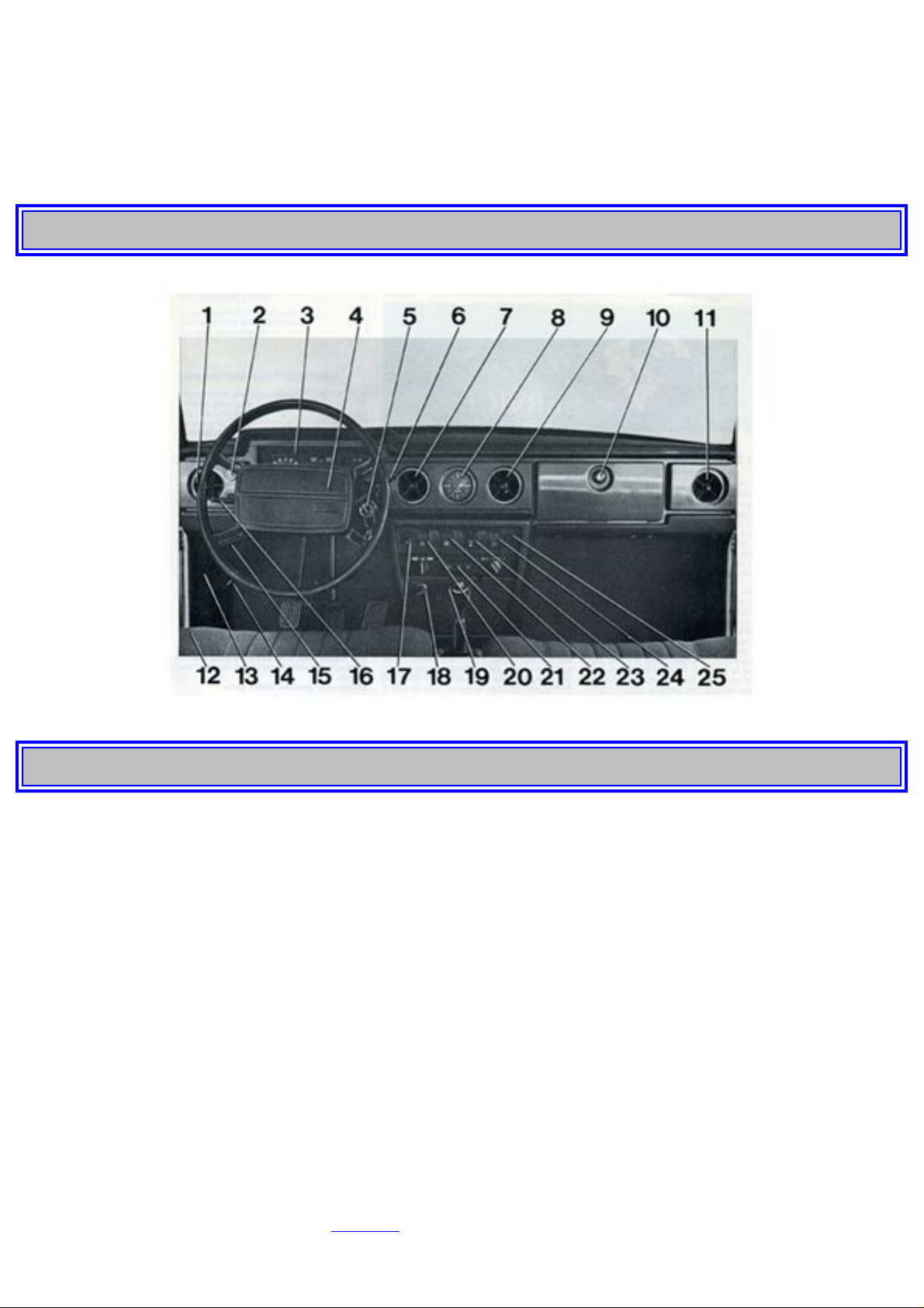
INSTRUMENTS AND CONTROLS
1. Air vent
2. Headlight switch
3. Combined instrument
4. Horn
5. Ignition switch and steering wheel lock
6. Windshield wiper/washer control lever
7. Air vent
8. Clock
9. Air vent
10. Glove locker
11. Air vent
12. Parking brake
13. Fuse box (fuse replacement, see page 60)
http://new.volvocars.com/ownersdocs/1974/1974%20142%20144%20145/74142144145_01.htm (1 sur 32) [2013-03-14 11:43:46]
Page 6
1974 Volvo 142 144 145
14. Fresh-air intake vent
15. Hood release handle
16. Turn signal, switch lever, dimmer and headlight flasher
17. Rheostat for instrument panel lighting
18. Cigarette lighter
19. Ash tray
20. Switch for tailgate window wiper/washer (145)
21. Heater and ventilation controls
22. Switch, electrically heated rear window
23. Switch, emergency warning flashers
24. Fan switch
25. Seat belt reminder light
The instruments and controls are described in more detail in the following pages with a reference to
the numbers in the picture above.
1, 7, 9, 11 Air vents
Air is supplied to the compartment by means of the four air vents. Air is blown through these vents by
the blower fan which is operated by switch (see page 12). The vents can be shut off completely by
turning the button in the center of each vent a 1/4 turn anti-clockwise. The vents can also be adjusted
to point to any particular place in the compartment. The two outer vents can even be used for
demisting the front door windows.
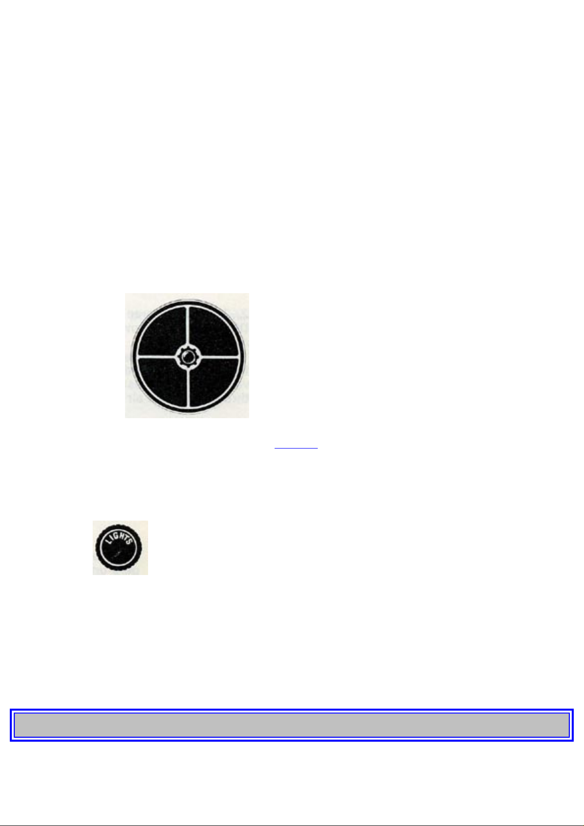
2 Light switch
The headlights are operated by a push-pull type switch on the dash-board as well as a lever (16) on the
steering column.
All the lights are extinguished when the light switch is pushed fully in. Pulling it out to the half-way
position, switches on the parking lights, and when it is fully out, the upper or lower beams are
switched on, depending on the position of the lever (16).
Since the lighting system is not connected across the ignition switch, the lights will function
irrespective of whether the ignition key is in position or not.
pg. 6 OPERATING INSTRUCTIONS
http://new.volvocars.com/ownersdocs/1974/1974%20142%20144%20145/74142144145_01.htm (2 sur 32) [2013-03-14 11:43:46]
Page 7
1974 Volvo 142 144 145
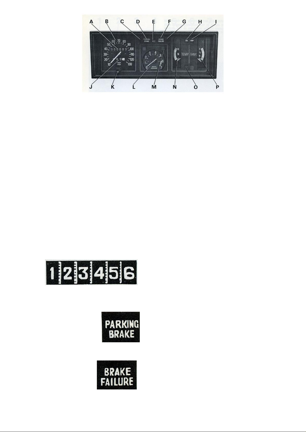
3 Combined Instrument
A Odometer
B Speedometer
C Left turn indicator light (green)
D Parking brake warning light (red)
E Upper beam control light (blue)
F Brake circuit warning light (red)
G Right turn indicator light (green)
H Oil pressure warning light (red)
I Battery charge warning light (red)
J Trip odometer
K Trip odometer reset knob
L Tachometer
M Bulb Integrity Sensor warning light (yellow)
N Temperature gauge
0 Overdrive control light (green)
P Fuel gauge
A Odometer
The odometer shows the total distance covered in miles. After 999999 miles it returns to zero and
starts to go round again.
D Parking brake warning light
This light gives a steady, red light when the ignition is on and the parking brake applied.
F Brake circuit warning light
This light gives a steady red light should a failure arise in one of the brake circuits. If the light goes on
during driving, the car should be driven to a workshop to check the brake system.
http://new.volvocars.com/ownersdocs/1974/1974%20142%20144%20145/74142144145_01.htm (3 sur 32) [2013-03-14 11:43:46]
Page 8
1974 Volvo 142 144 145
Observe due care when driving under these conditions.
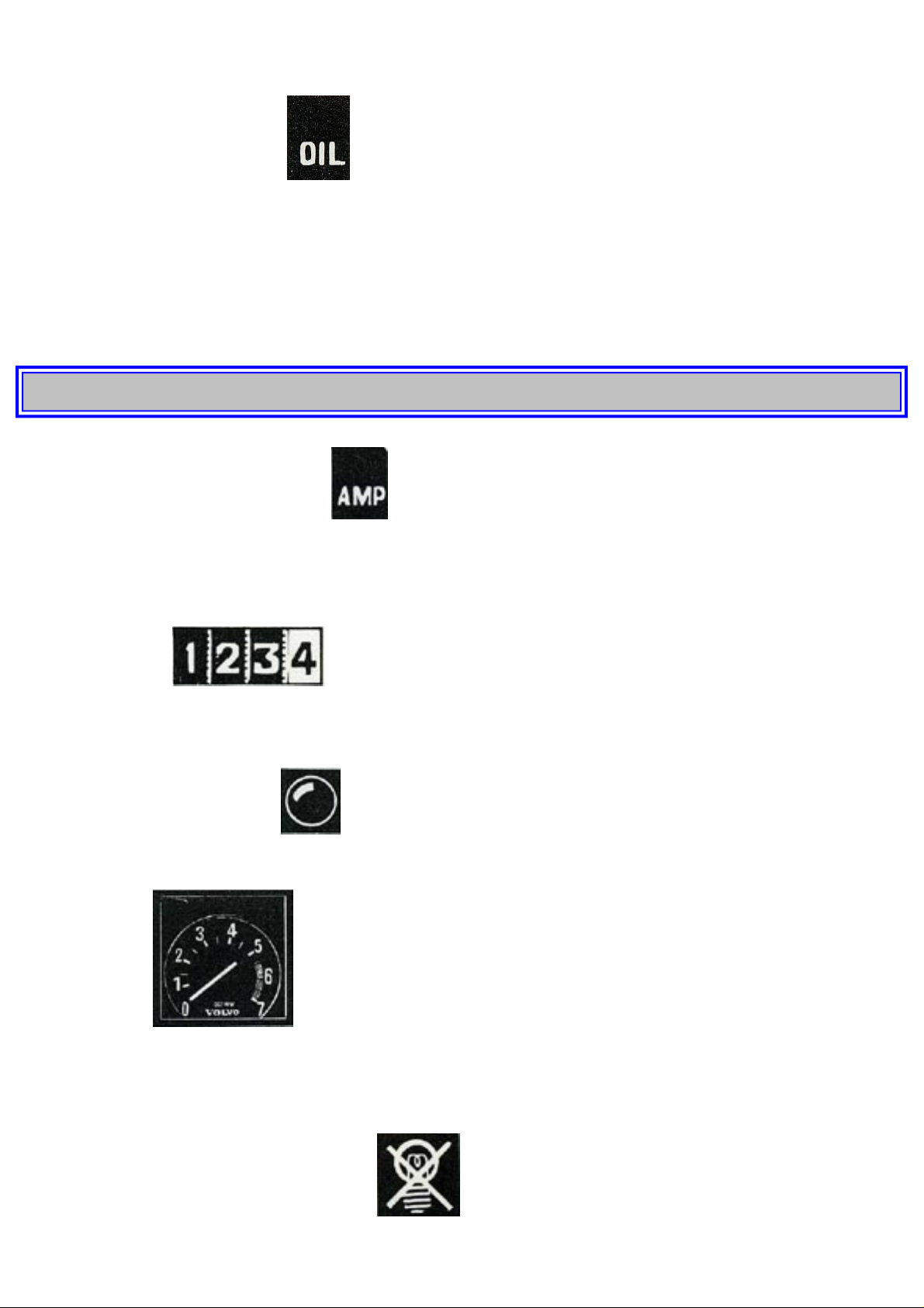
H Oil pressure warning light
This lights red when the engine oil pressure is too low. When the ignition is switched on, the light
should go on and then go out again when the engine starts. Never start driving until the light goes out.
If the light goes on during driving, stop the engine and find out the reason for this. In most cases it
means that the oil level is too low. After hard driving it may happen that the warning light comes on
when the engine is idling. This is normal providing it goes out again when engine speed is
increased.
pg. 7 OPERATING INSTRUCTIONS
I Warning light, battery charging
This lights red when the battery is discharging. Should it light during driving, either there is some
fault in the electrical system or the fan belt is not sufficiently tensioned and is thus slipping on the
alternator pulley, causing poor charging.
J Trip odometer
The trip odometer measures distances of up to maximum 999 miles. The window furthest to the right
shows tenths of a mile and is therefore useful for measuring short distances.
K Trip odometer reset knob
The trip odometer is reset to zero by pushing in the knob.
L Tachometer
The tachometer shows the engine rpm in thousands per minute. The area marked in orange color
between 6000 rpm and 6500 rpm indicates rpm-ranges momentarily permitted and may be used for
instance during fast acceleration. The rpm-area 6500 - 7000 rpm is marked red and must not be used.
M Bulb Integrity Sensor warning light
The light gives a steady yellow light should any of the bulbs for lower beam, tail light or license light
http://new.volvocars.com/ownersdocs/1974/1974%20142%20144%20145/74142144145_01.htm (4 sur 32) [2013-03-14 11:43:46]
Page 9
1974 Volvo 142 144 145
(not Volvo 145) go out. If any one of the stop lights is out, the warning light comes on when the brake
pedal is applied.
The light comes on when the ignition is switched on and goes out when the engine starts.
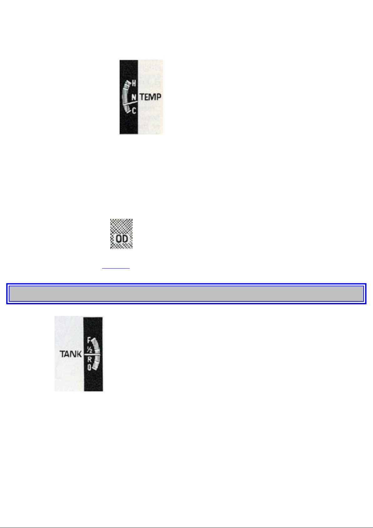
N Coolant temperature gauge
The temperature gauge shows the temperature of the coolant and thus indicates the working
temperature of the engine. The gauge pointer should normally remain within the green sector.
During town driving and idling when the weather is particularly warm, the temperature gauge pointer
may enter the amber field.
Should the pointer repeatedly point to the solid red field, coolant and fan belt tension should be
checked.
0 Warning lamp, overdrive
The lamp gives a steady green light when the overdrive is engaged. Concerning engaging and
disengaging overdrive, see
page 26.
pg. 8 OPERATING INSTRUCTIONS
P Fuel gauge
The fuel gauge is graduated "full", "half", "reserve", and "empty". The red field between "reserve" and
"empty" is a reminder that the tank should be filled. When the gauge pointer is on "reserve", there are
approx. 2 1/2 US galls/2 Imp. galls (8 liters) in the tank. The gauge pointer registers when the ignition
is switched on.
4 Horn
The horn blows when the pad in the center of the steering wheel is pushed in and the ignition has been
switched on.
http://new.volvocars.com/ownersdocs/1974/1974%20142%20144%20145/74142144145_01.htm (5 sur 32) [2013-03-14 11:43:46]
Page 10

1974 Volvo 142 144 145
5 Combined ignition switch and steering wheel lock
The switch has four positions: (0) Locking, (1) Intermediate, (2) Driving and (3) Starting. The key
can be taken out of the lock only in the Locking position.
On the rear cover inside page you will find space for noting the number of the door key and the
ignition key. If a key gets lost, contact your nearest Volvo dealer for new ones and indicate the
number of the lost key.
The ignition switch is provided with a buzzer to remind the driver should he forget to remove the
ignition key when his door is opened.
Removing the key automatically locks the steering wheel.
With the key in the Intermediate position, the steering wheel is not locked and some electrical
components are switched on.
To start the engine, turn the key to the Starting position. This engages the starter motor. As soon as
the engine starts, release the key which automatically returns to the Driving position.
Note: If this vehicle is equipped with an ignition interlock system as required by US safety standards,
the engine cannot be started unless the driver and front seat passenger have fastened their seat belts.
Because of a special sequencing circuit in the belt interlock control, the seat belts must be fastened
after the occupant is seated and before the key is turned to the starting position. If the proper sequence
is not followed, the seat belt reminder light and buzzer are actuated and the engine will not start (see
Engine Starting Instructions on
page 25).
If the car is parked in such a way as to make it difficult to unlock the steering wheel, unlocking
can be made easier by slightly turning the steering wheel one way and then the other.
When the ignition is switched on, but before the engine has started, the following lights will be on:
● Oil pressure warning light
● Battery charge warning light
● Bulb Integrity Sensor warning light
● Parking brake warning light
● Brake circuit warning light
This is an indication that the lights function. When the engine has started, all lights should be out
(except the Parking brake warning light if the parking brake should be applied).
pg. 9 OPERATING INSTRUCTIONS
http://new.volvocars.com/ownersdocs/1974/1974%20142%20144%20145/74142144145_01.htm (6 sur 32) [2013-03-14 11:43:46]
Page 11
1974 Volvo 142 144 145
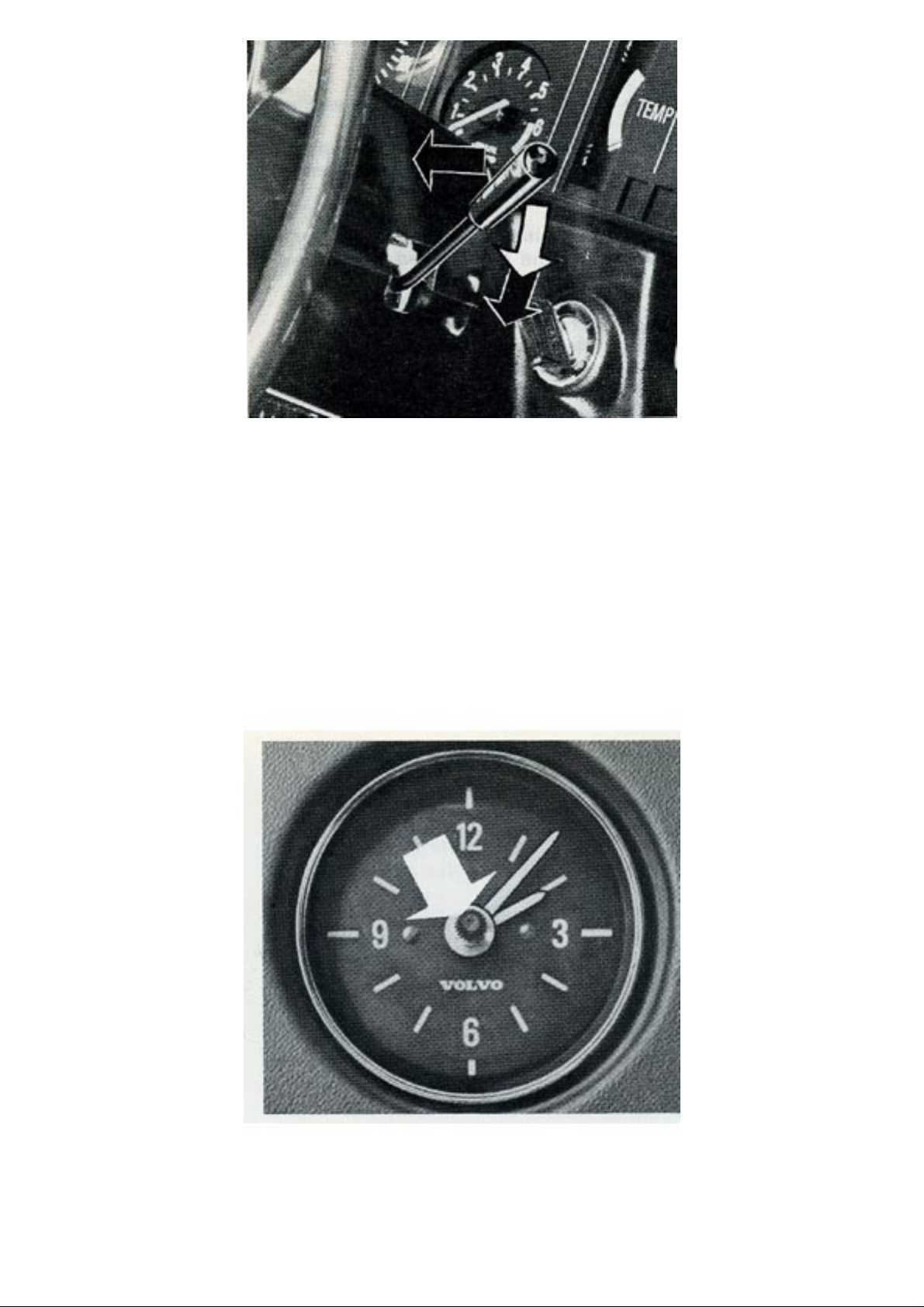
6 Windshield wiper/washer control lever
The windshield wipers have two speeds. Moving the lever downwards one stage operates the wipers
at normal speed. This speed is recommended for normal driving in rain or snow. Pushing the lever
down fully operates the wipers at full speed. This is recommended only when driving in heavy rain or
when driving at high speed in the rain.
The windshield washer is switched on by moving the control laver towards the steering wheel. The
washer can be used even when the wipers are not switched on.
The washer container is located in the engine compartment and holds about 1.3 US gallons = 1.1 Imp.
gallon = 5 liters.
8 Clock
The clock is operated electrically. To reset it, push in the re-setting knob and turn the hands.
http://new.volvocars.com/ownersdocs/1974/1974%20142%20144%20145/74142144145_01.htm (7 sur 32) [2013-03-14 11:43:46]
Page 12
1974 Volvo 142 144 145
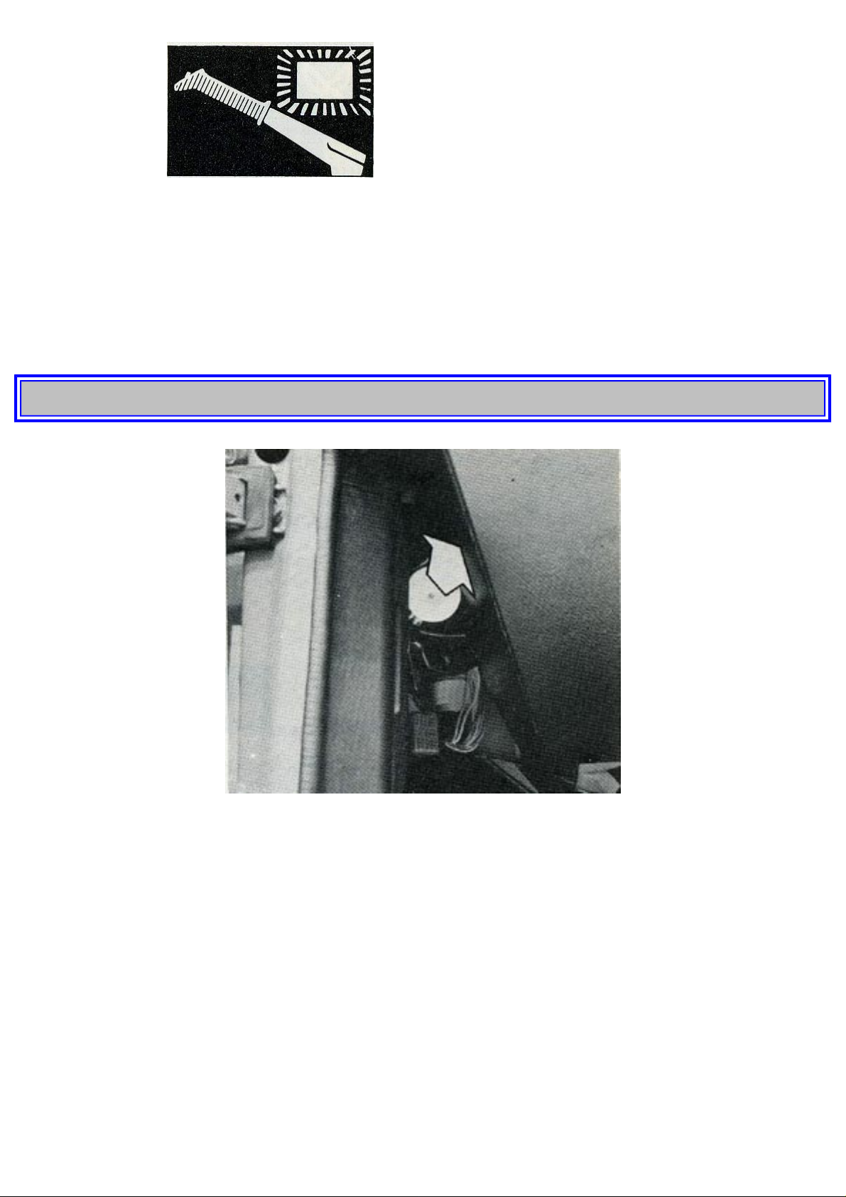
12 Parking brake
The parking brake lever is on the outside of the driver's seat and operates on the rear wheels only.
When the parking brake is applied and the ignition is on, a red warning light (3, D) shows on the
instrument panel.
14 Fresh-air control
Pushing the control forwards opens fresh air intake vents on the left side. Note that the fan should not
be operating if cool air is desired through this vent.
pg. 10 OPERATING INSTRUCTIONS
15 Hood release handle
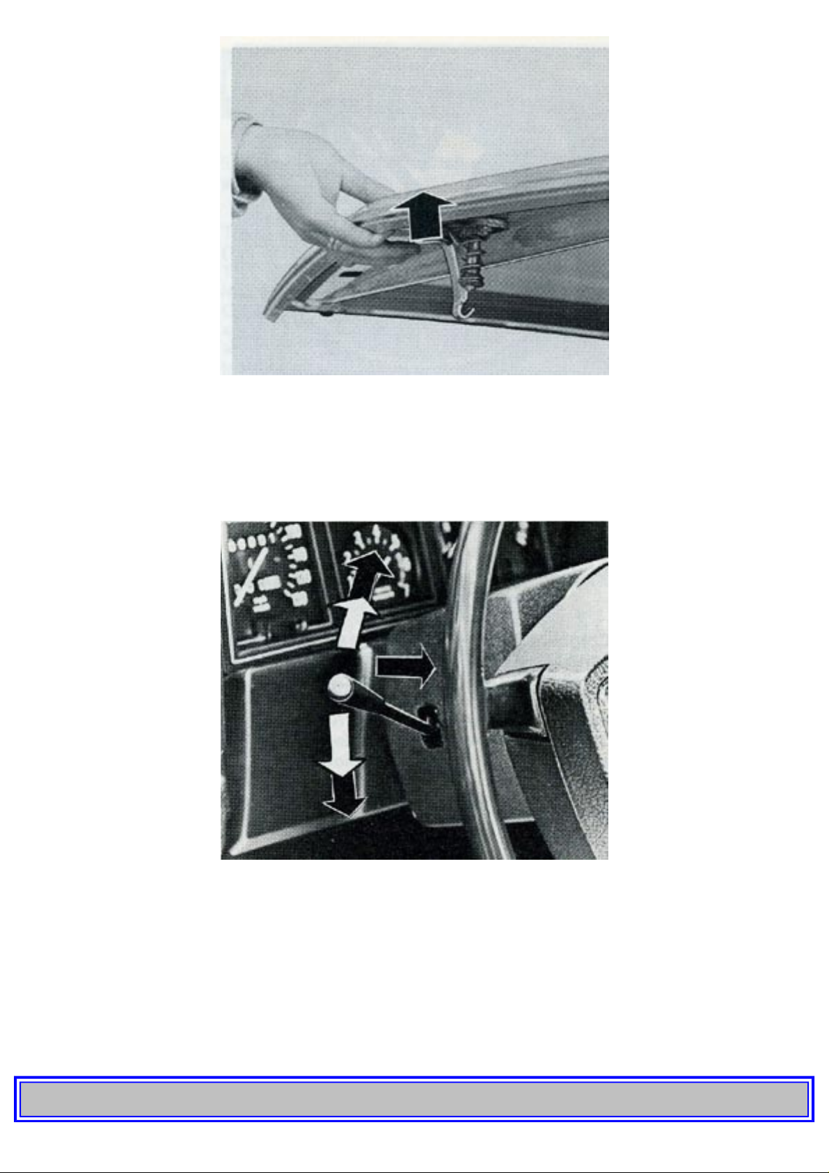
The hood is released by pulling out the handle situated to the extreme left under the dash. This
releases the hood which is still held by the safety latch.
http://new.volvocars.com/ownersdocs/1974/1974%20142%20144%20145/74142144145_01.htm (8 sur 32) [2013-03-14 11:43:46]
Page 13
1974 Volvo 142 144 145
The hood is opened by inserting the fingers under the front edge and pressing in the catch.
Check that it shuts properly when closed. The location of the hood when closed can be adjusted if
necessary by screwing in or out the rubber plugs underneath the hood at the front end and on the
mudguards below the windshield.
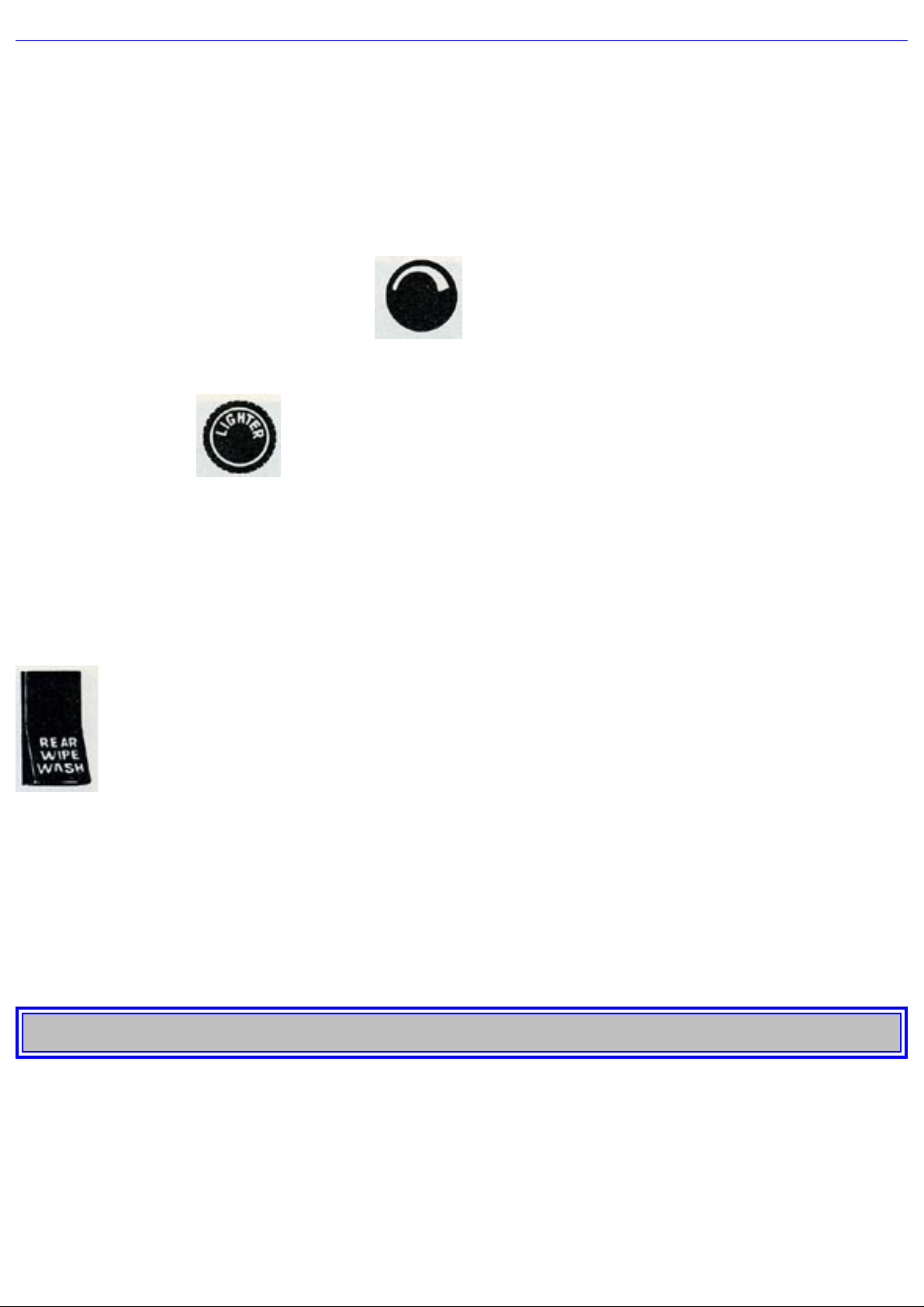
16 Turn signal lever, dimmer and headlight flasher
The lever on the left-hand side of the steering column just below the steering wheel controls turn
signals, headlights and headlight flasher. The lever has a stop point for lane changing. This means that
with small swings on the steering wheel (when, e.g., changing lanes, passing, etc.) the lever can be
moved up or down to this point and kept there. The right or left signal will then start flashing. When
the switch lever is released, it automatically returns to its off position. For normal swings on the
steering wheel, the lever is moved past this stop point to the end position.
pg. 11 OPERATING INSTRUCTIONS
http://new.volvocars.com/ownersdocs/1974/1974%20142%20144%20145/74142144145_01.htm (9 sur 32) [2013-03-14 11:43:46]
Page 14
1974 Volvo 142 144 145
Straightening up the steering wheel will return the lever to its off position. Switching from upper
beams to lower beams and vice versa is made by moving the lever towards the steering wheel and
then releasing it. Here the lighting switch (2) should be pulled fully out.
The lever is also used for flashing with upper beams when the headlights are not switched on. The
headlight flasher is switched on by moving the lever towards the steering wheel and it remains
switched on until the lever is released.
17 Rheostat for instrument panel light
Rotate knob clockwise to turn on panel light and counterclockwise to dim it.
18 Cigarette lighter
To use the cigarette lighter, push it in. The lighter releases automatically when it attains sufficient
heat.
19 Ash tray
To empty the ash tray, pull it straight out all the way while pressing down the tongue inside.
20 Tailgate window wiper/washer switch (145 Station Wagon)
The switch for the tailgate window wiper/washer is in the form of a tangent. At the first notch, both
wiper and washer are engaged. To keep both operating, the switch must be held in position by the
hand.
Pushing the lower part of the switch in fully operates only the wiper. It is stopped by pushing in fully
the upper part of the hand. The fluid container for the washer is placed in the cargo space at the very
back, to the right, and holds about 3 1/4 US pints, 2 3/4 Imp. pints (1 1/2 liters).
pg. 12 OPERATING INSTRUCTIONS
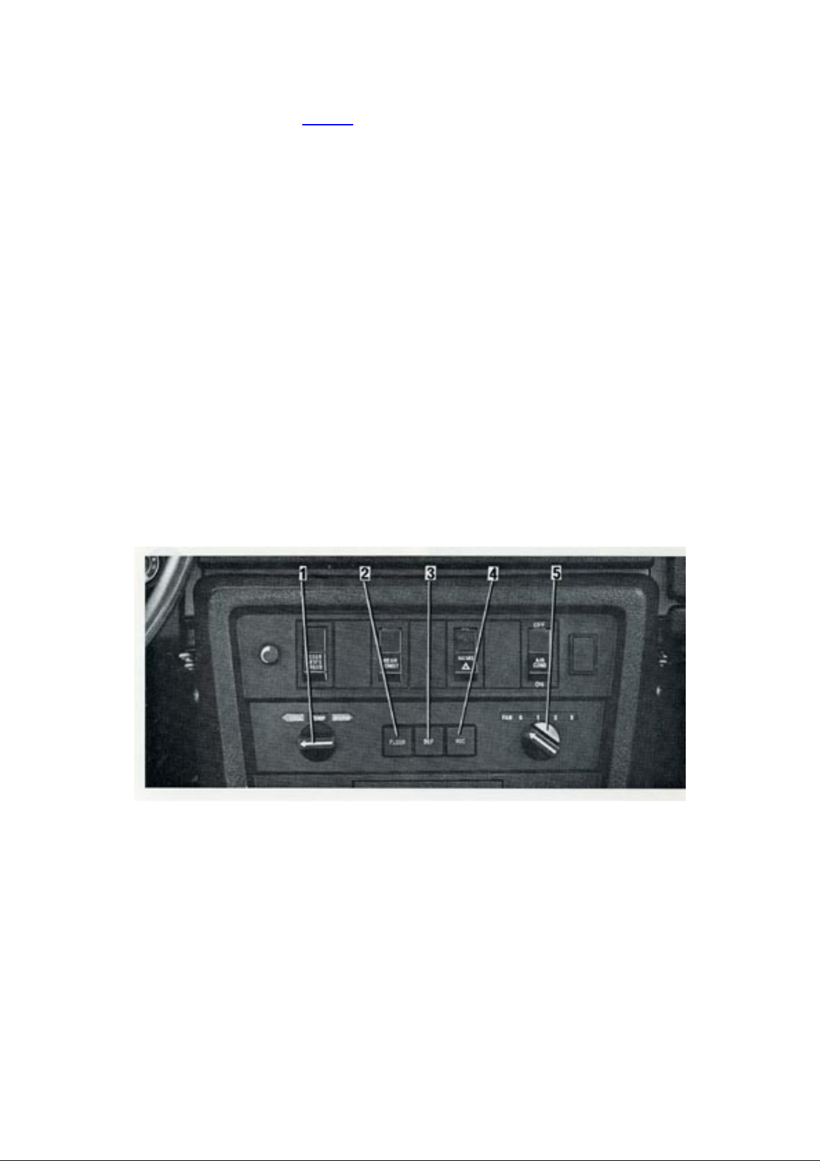
21 Heater/ventilation controls
The heating system is a combined warm air and fresh air system, available with or without air
conditioner.
The system comprises the following controls:
1. TEMP (temperature)
2. FLOOR (floor)
http://new.volvocars.com/ownersdocs/1974/1974%20142%20144%20145/74142144145_01.htm (10 sur 32) [2013-03-14 11:43:46]
Page 15
1974 Volvo 142 144 145
3. DEF (defroster)
4. REC (recirculation)
5. FAN (fan)
and partly also the four air vents, see page 5.
1. TEMP controls the incoming air temperature.
Counter-clockwise = COOL.
Clockwise = WARM.
2, 3, 4. The three push buttons FLOOR, DEF and REC provide well-balanced standard settings.
No buttons pushed In: No air to floor and very little to defroster. Air can be obtained through the
four air vents.
Only FLOOR pushed in: Full air flow to front and rear floor, very little to defroster.
Only DEF pushed in: Full defroster, no air to floor.
Push button REC is intended to be used in combination with air conditioner (extra equipment) and
should not be used for heating.
5. FAN controls the fan speed.
0 = Off.
3 = Full speed (mainly intended for air conditioner).
In order to obtain high temperature fast, adjust:
TEMP fully clockwise.
FAN position 2 (use pos. 3 in extreme cases, only).
FLOOR pressed in, only.
Air vents half way open.
This adjustment reduces the defroster efficiency.
http://new.volvocars.com/ownersdocs/1974/1974%20142%20144%20145/74142144145_01.htm (11 sur 32) [2013-03-14 11:43:46]
Page 16
1974 Volvo 142 144 145
If you want to avoid or rapidly remove mist inside the windows, adjust:
TEMP fully clockwise
FAN position 2 (use pos. 3 in extreme cases only)
DEF pushed in, only
The outer air vents half way open.
When starting a snow-covered car, any snow covering the heater air intakes should be removed to
avoid misting.
pg. 13 OPERATING INSTRUCTIONS
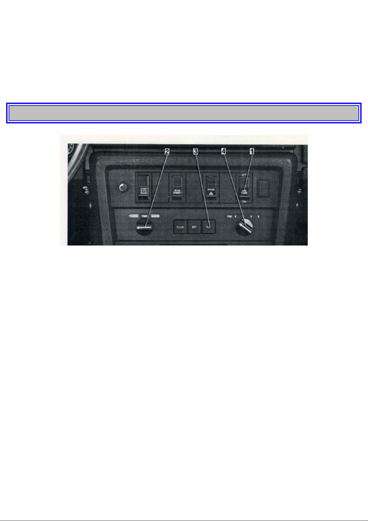
Air conditioner (optional)
1. Switch on the compressor with AIR COND.
2. Turn control TEMP to COOL( fully counter-clockwise) for rapid cooling. Thereafter, choose
desired temperature.
3. Push in button REC for rapid cooling. When desired temperature has been obtained, the button
may be pulled out again.
4. Select suitable fan speed with control FAN.
The best cooling effect is reached by keeping all windows closed and none of the buttons FLOOR or
DEF pushed in.
Most of the cooled air will then enter the four dash air vents which should be fully open.
A good tip: For rapid removal of mist, the air conditioner can be switched on also at temperatures
when it normally not should be used.
1. AIR COND pushed in.
2. REC pushed in.
3. FAN position 2 (use pos. 3 in extreme cases only).
http://new.volvocars.com/ownersdocs/1974/1974%20142%20144%20145/74142144145_01.htm (12 sur 32) [2013-03-14 11:43:46]
Page 17
1974 Volvo 142 144 145
4. TEMP regulated to desired temperature.
Run the air conditioner a few times every month, also in wintertime when it is not used, in order to
lubricate the compressor seals.
Check the air conditioner yearly at a Volvo shop.
pg. 14 OPERATING INSTRUCTIONS
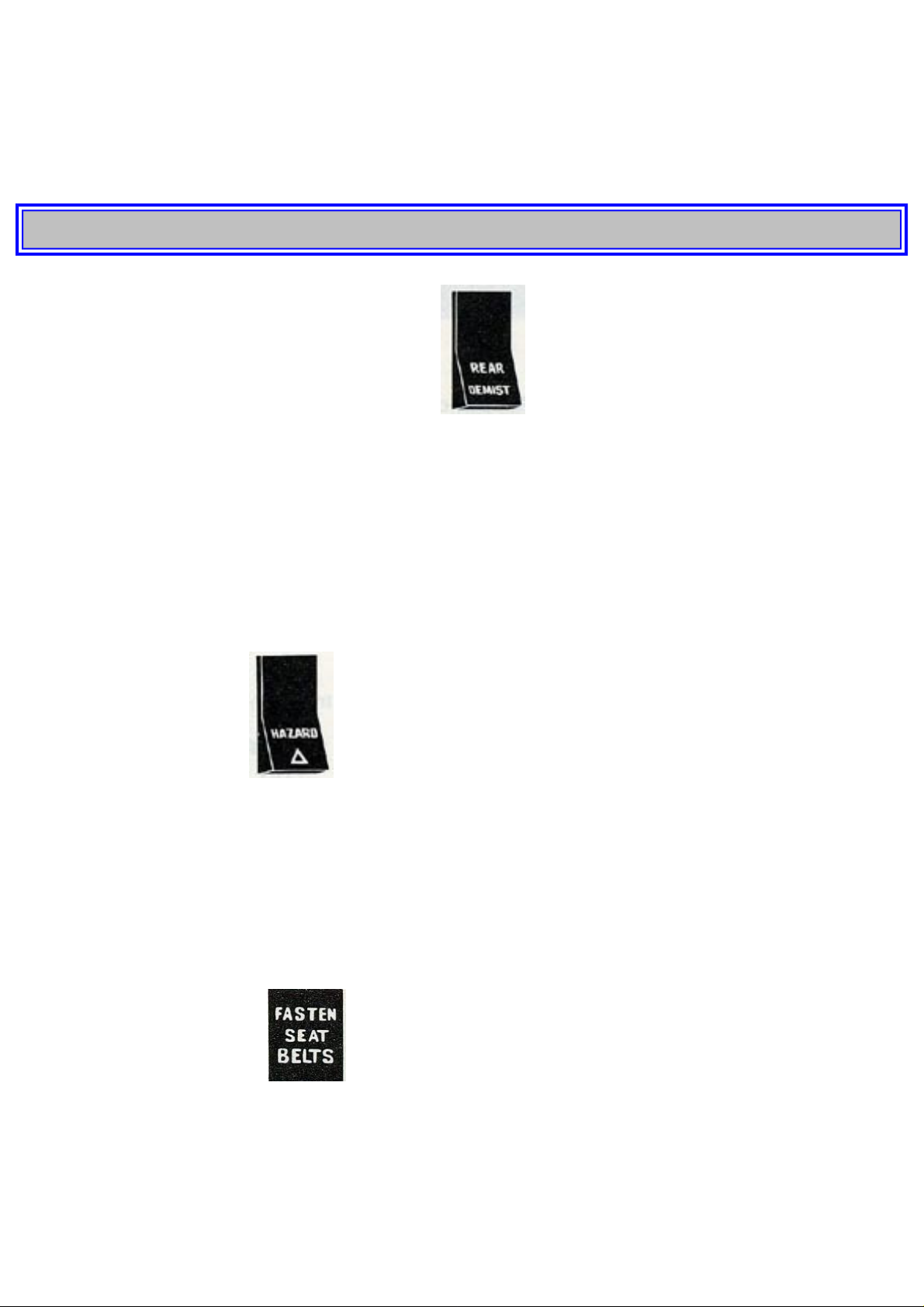
22 Switch for electrically heated rear window
In order to obtain a clear rear view during cold and damp weather, the car is equipped with an
electrically heated rear window. Heating is provided by wires on the inside of the rear window. Avoid
placing anything near the wires that might damage them. Observe due care when cleaning the
window inside, as rings etc may damage the wires.
The heating is switched on by pushing in the lower part of the switch. This lights up a warning lamp
mounted in the switch. Pushing in the upper part of the switch switches off the heating.
Switch off the heating when the rear window is clear of mist and ice in order not to overload the
battery unduly.
23 Switch for emergency
All four emergency warning lights start flashing when the lower part of the switch is pushed in. A
warning lamp in the switch blinks in union with them. This warning light is not wired across the
ignition and therefore functions irrespective of whether the ignition is switched on or not.
Pushing in the switch again puts out the flasher lights.
The emergency warning lights should only be used when the car must be stopped where there is
danger to other traffic. Note that regulations concerning the use of these lights may vary from place to
place.
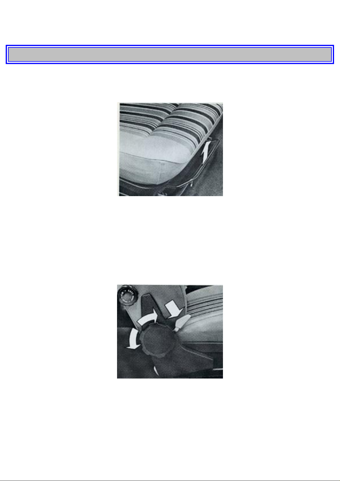
25 Seat belt reminder light
If either front seatbelt is unfastened after the engine has been started with the gear selector in any
forward gear, the seat belt reminder light and buzzer will actuate.
Note: If this vehicle is equipped with an ignition interlock system and the ignition key is turned to the
starting position without first fastening the front seat belts, the seat belt reminder light and buzzer will
actuate and the starter will not engage. Should the light and buzzer actuate while the engine is
running, even though the seat belts are fastened, it is an indication that the belt interlock control is out
http://new.volvocars.com/ownersdocs/1974/1974%20142%20144%20145/74142144145_01.htm (13 sur 32) [2013-03-14 11:43:46]
Page 18
1974 Volvo 142 144 145
of sequence, and the starter will not engage should the engine stop. In this case, release and refasten
the front seat belts at each occupied position which should turn off the reminder light and buzzer.
pg. 15 OPERATING INSTRUCTIONS
INTERIOR AND BODY
Front seats
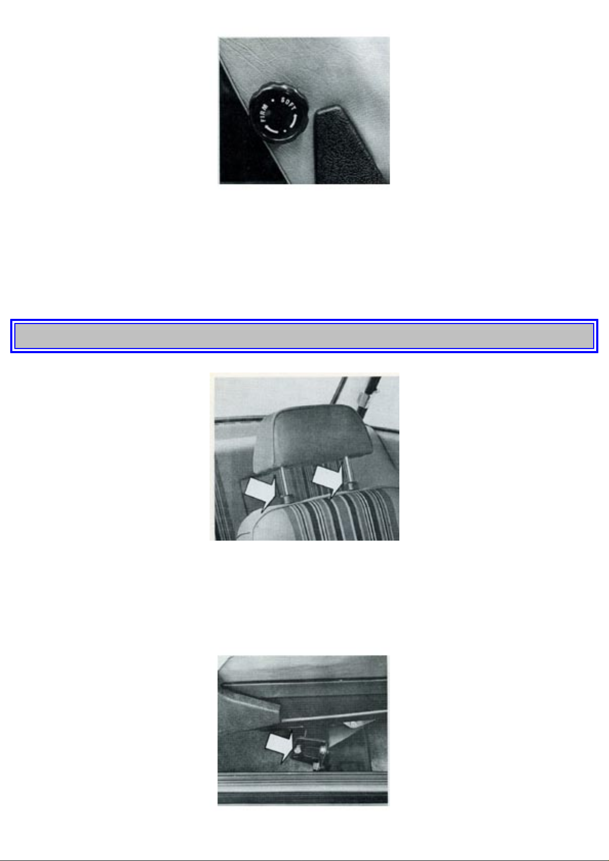
The front seats can be moved forwards and backwards after the loop handle on the seat front has been
pulled upwards. Exert leverage with your feet on the floor and slide the seat to position desired.
The seat back inclination is invariably adjustable by a hand wheel.
Certain models have electrically heated seat cushions and seat backs. The seat cushion is provided
with a thermostat which cuts in when the cushion temperature is below +14°C = 57°F and cuts out at
+26°C = 78°F. The heater pad is energized only when the ignition is on.
Seat back latches
The front seat back in the Volvo 142 model is latched against forward tilting. To fold the seat back
forwards, the latch device must be released by pressing down the lever as shown in the picture.
http://new.volvocars.com/ownersdocs/1974/1974%20142%20144%20145/74142144145_01.htm (14 sur 32) [2013-03-14 11:43:46]
Page 19
1974 Volvo 142 144 145
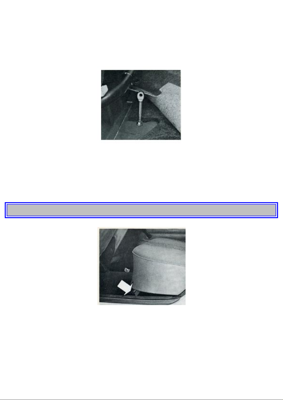
Lumbar support
The front seats are provided with an adjustable lumbar support. Adjustment is by means of the knob
on the backrest. To tension the lumbar support, and thus exert more pressure against the small of the
back, turn the knob clockwise "FIRM", and to relieve the pressure against the small of the back, turn
the knob anti-clockwise "SOFT".
pg. 16 OPERATING INSTRUCTIONS
Head restraints
The front seats are equipped with adjustable head restraints. Before driving, you should always make
sure that the head restraints is adjusted to your height. Adjust by slackening the plastic nuts on the
head restraints retainers, see picture. After adjustment, lock by turning the plastic nuts clockwise.
http://new.volvocars.com/ownersdocs/1974/1974%20142%20144%20145/74142144145_01.htm (15 sur 32) [2013-03-14 11:43:46]
Page 20
1974 Volvo 142 144 145
Adjustment
The seat level can be adjusted to three different positions. To do this, remove the seat cushion in order
to reach the bolts in the seat bracket. Remove the two bolts attaching the frame to the seat bracket. Set
the seat to the desired position and fit the bolts into the holes which are at the same height on both
sides.
When this adjustment is being made it may also be desirable or necessary to adjust the entire
inclination angle of the seat. This is done with the eyelet screw at the front under the seat frame.
Remove the bolt which goes through the eyelet and tilt the seat backwards. Then slacken the lock nut
on the floor and adjust the eyelet screw to the desired height. Re-install the bolt and secure the eyelet
screw with the lock nut.
pg. 17 OPERATING INSTRUCTIONS
Rear seat 145 Station Wagon
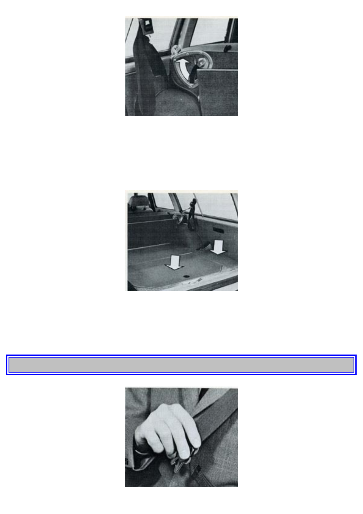
The rear seat back can be folded if extra cargo space is required. This is done as follows:
1 Push down one of the levers at the seat cushion front (rear or left side) and lift at the same time up
the cushion towards the front seat backs.
http://new.volvocars.com/ownersdocs/1974/1974%20142%20144%20145/74142144145_01.htm (16 sur 32) [2013-03-14 11:43:46]
Page 21
1974 Volvo 142 144 145
2 Move up one of the parallel-connected handles on the rear side of the seat back and fold the seat
back forward - downwards so that it lies flat. The rear seat back and seat are fixed automatically in
their respective positions. When folding up the seat back again, make sure that the latches grip
properly in their fittings. Make sure that the seat belts are on the top side of the seat cushion before it
is put back in its original position.
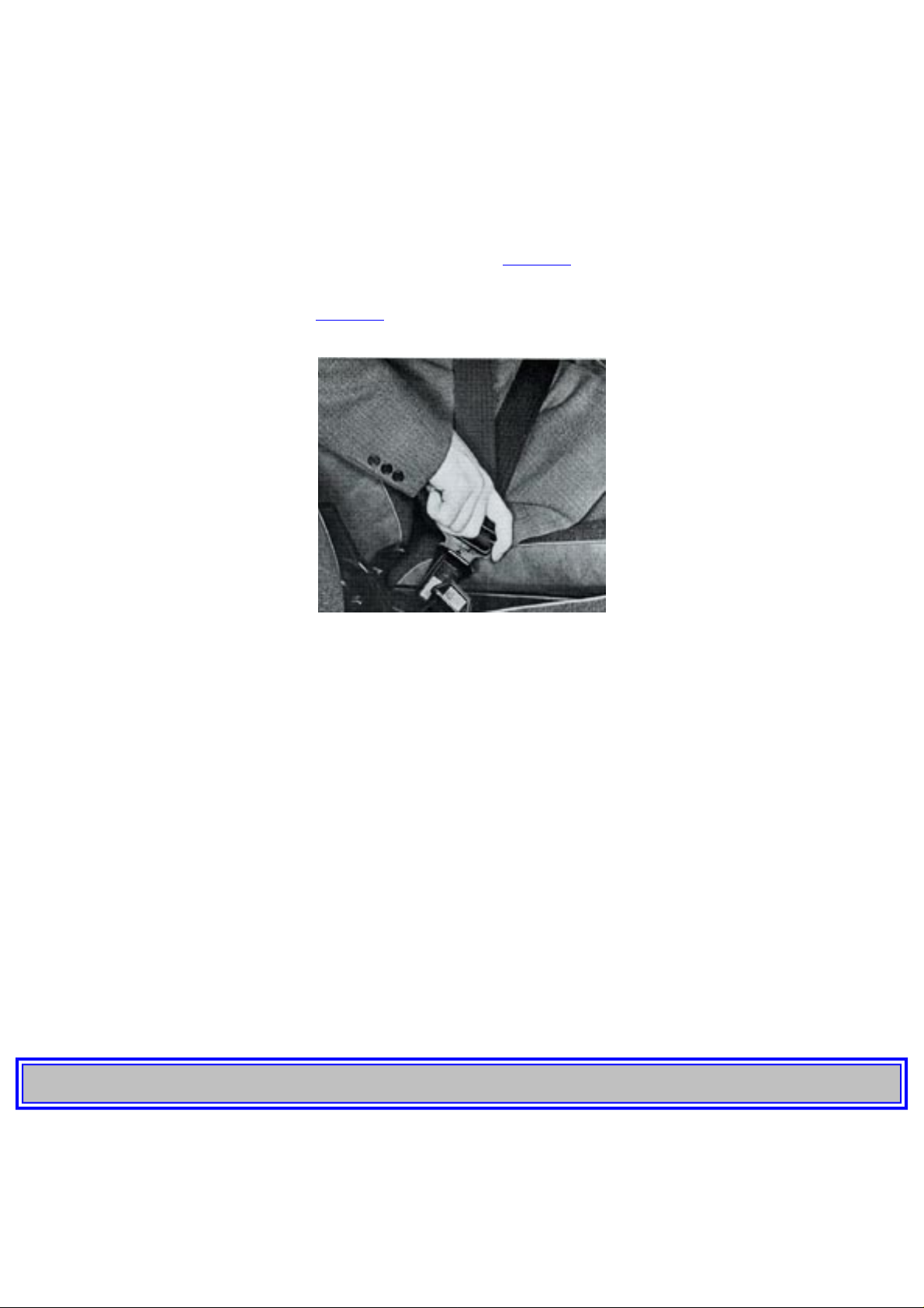
Extra storage space 145 Station Wagon
Underneath the floor of the cargo compartment there is extra storage space, which is accessible by
removing its cover. The tool set is located in this space.
The container for the rear window washer is located in the spare space all the way to the rear.
pg. 18 OPERATING INSTRUCTIONS
http://new.volvocars.com/ownersdocs/1974/1974%20142%20144%20145/74142144145_01.htm (17 sur 32) [2013-03-14 11:43:46]
Page 22
1974 Volvo 142 144 145
Seat belts
Always use the seat belt for all types of driving. Remember that it is possible even in slow city traffic
to incur serious injury from sudden, unexpected stopping.
Note: If this vehicle is equipped with an Ignition Interlock System as required by U.S. Safety
Standards, the engine cannot be started unless the driver and front seat passenger have fastened their
seat belts. The seat belts must be fastened after the occupant is seated and before the key is turned to
the starting position (see engine starting Instructions on
page 25).
There is a buzzer and a warning light on the instrument panel which both remind the driver that the
seat belts have to be fastened. See
page 14.
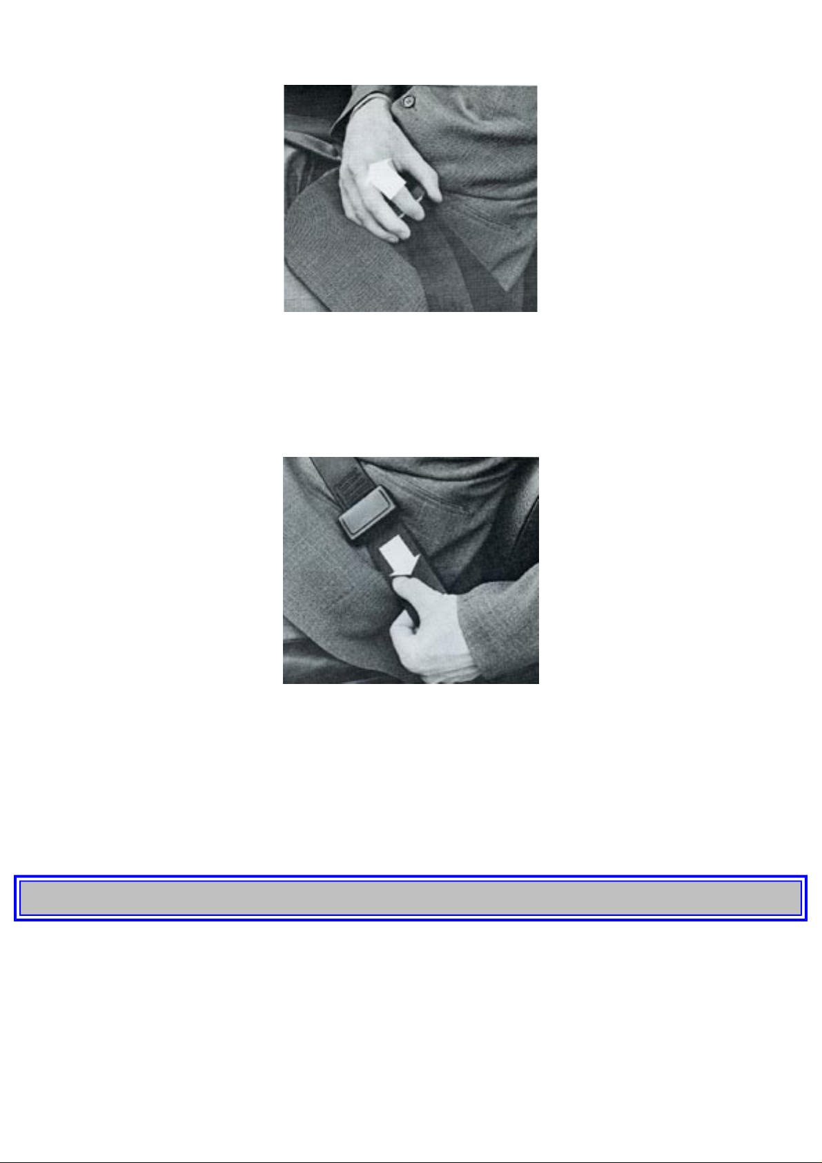
Your car is equipped with automatically retracting inertia seat belts.
To fasten the belt, pull out the strap slowly (with right hand for belt on left hand side, with left hand
for belt on right hand side) to prevent the mechanism from locking. Normally the belt roller is
"unlocked". The roller will lock automatically if pulled out quickly, or if the car brakes or inclines to
an angle greater than 10-15° or when taking a bend rather sharply.
The practical design of the belt makes it very easy to use. Place the belt with one strap over the lap
and the other across the shoulder-chest and fasten it by pushing the buckle tongue into the slot of the
locking device located between the front seats. A clearly audible clicking sound indicates that the belt
is locked. Make sure that those parts of the belt against the body are not twisted.
The belt is released from the lock by pushing in the square red button on the lock. Always make a
habit of letting the belt roller pull in the belt strap when the belt is unfastened.
If the belts do not retract fully, this may be due to the fact that they are twisted inside their casing.
This is remedied by pulling out the belt fully and then allowing it to be drawn into the casing.
Note that small children (up to the age of 8-10 years) should not use the seat belts.
pg. 19 OPERATING INSTRUCTIONS
Seat belts in rear seat
The seat belts at both sides of the rear seat are also of the automatic retracting type. When fastening
these belts pull them out rather slowly to prevent them from locking before being fastened. These
belts are fastened by pushing the tongue at the end of one strap into the lock on the other. To unfasten
http://new.volvocars.com/ownersdocs/1974/1974%20142%20144%20145/74142144145_01.htm (18 sur 32) [2013-03-14 11:43:46]
Page 23
1974 Volvo 142 144 145
just press in the square red button.
The belt in the middle of the rear seat is manually adjusted. It is fastened and unfastened in the same
way as the side belts in the rear seat.
To lengthen the center belt, turn the buckle and pull it out as shown in the picture.
To shorten the belt pull the upper belt strap.
Hang up the seat belt on its place when it is not in use.
Check now and then that the bolts are secure and the belt in good condition. Use water and a detergent
for cleaning.
As the seat belts lose much of their strength when exposed to violent stretching, they should be
replaced after collision, even though they may appear to be undamaged.
Never modify or repair the belt on your own, but have this done by a Volvo workshop.
pg. 20 OPERATING INSTRUCTIONS
http://new.volvocars.com/ownersdocs/1974/1974%20142%20144%20145/74142144145_01.htm (19 sur 32) [2013-03-14 11:43:46]
Page 24
1974 Volvo 142 144 145
Doors and locks
The car is equipped with a lock and keyhole on each of the front doors.
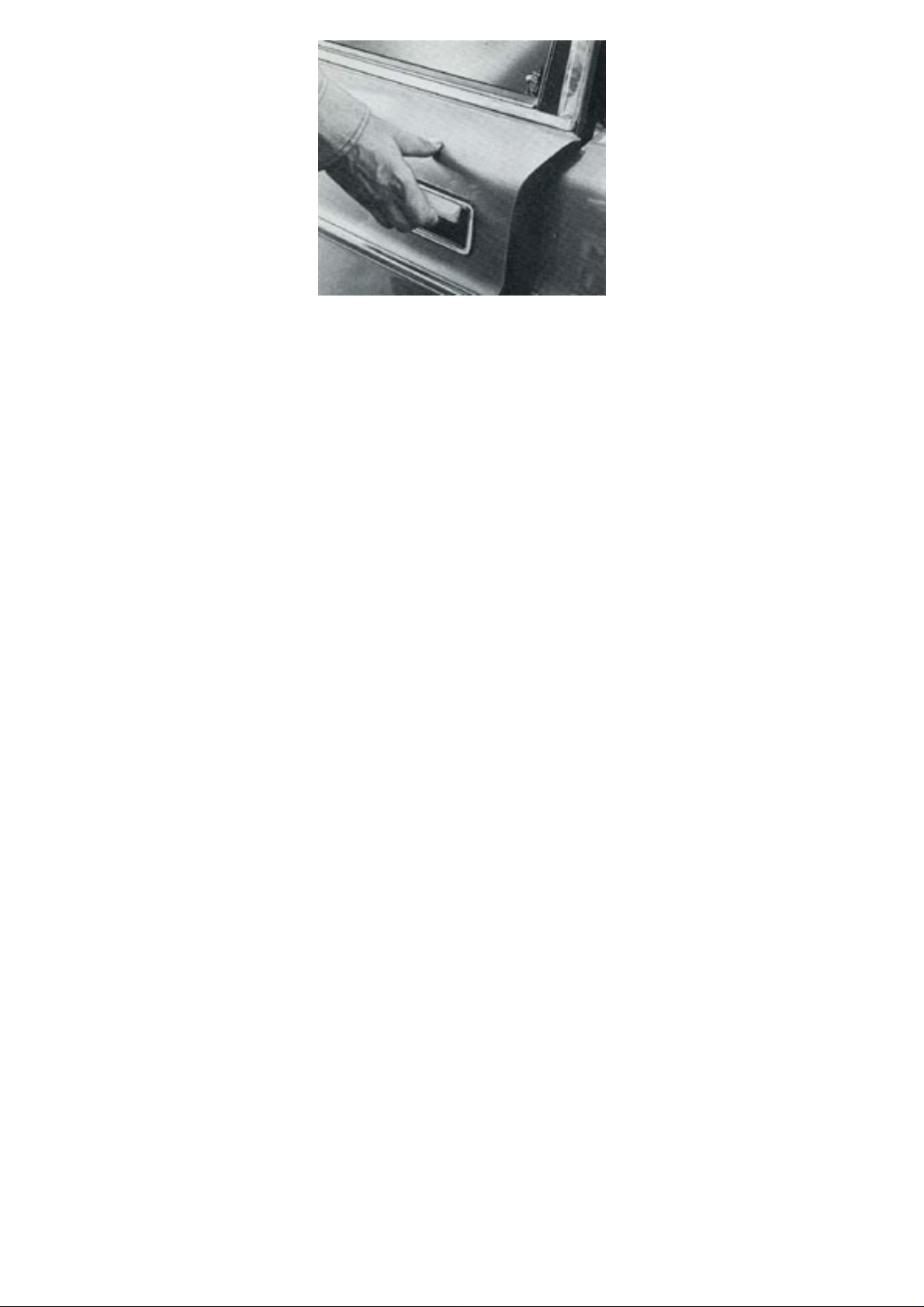
The front doors can be locked from the outside by pressing the lock button on the window ledge down
and shutting the door while holding the outside handle pulled out as shown in the picture.
To lock the rear doors, push down the inside lock button. It is not necessary to keep the outside handle
pulled out.
Do not leave the keys in the car.
All the doors can be locked on the inside by pressing down the lock button on the window ledge. On
the front doors this lock button lifts automatically when the door is opened from the inside. On the
rear doors, however, the lock button must first be pulled up before the doors can be opened from the
inside.
Note that the front doors are not better closed if the lock buttons are pressed down since this only
prevents the door from being opened from the outside.
During driving the lock buttons should not be pushed down as this would only prevent anyone
from opening the door on the outside should an accident occur.
The door locks have been designed to provide maximum possible protection against freezing during
the wintertime. As an extra measure, however, you should lubricate the locks regularly during very
cold weather with a suitable antifreeze agent. If the lock is already frozen, be careful not to break the
key in the lock. Instead, heat the key and immediately place it in the lock. This should unfreeze the
lock. Should you lose the car keys, contact your nearest Volvo dealer for new ones and quote the code
number of the keys which have been lost.
http://new.volvocars.com/ownersdocs/1974/1974%20142%20144%20145/74142144145_01.htm (20 sur 32) [2013-03-14 11:43:46]
Page 25
1974 Volvo 142 144 145
Child safety lock
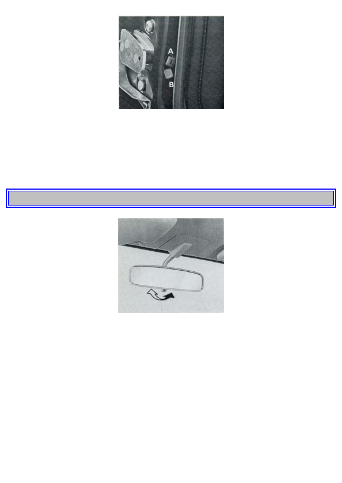
On the Volvo 144 and 145 there is a small red button located at the very back on the inside of the rear
doors. Move this button down to lower position (B). When the door is then closed, it cannot be
opened from the inside but, however, from the outside, providing the lock button on window ledge is
not depressed.
If the red button is at the upper position (A), the rear door lock will function normally.
pg. 21 OPERATING INSTRUCTIONS
Rear view mirrors
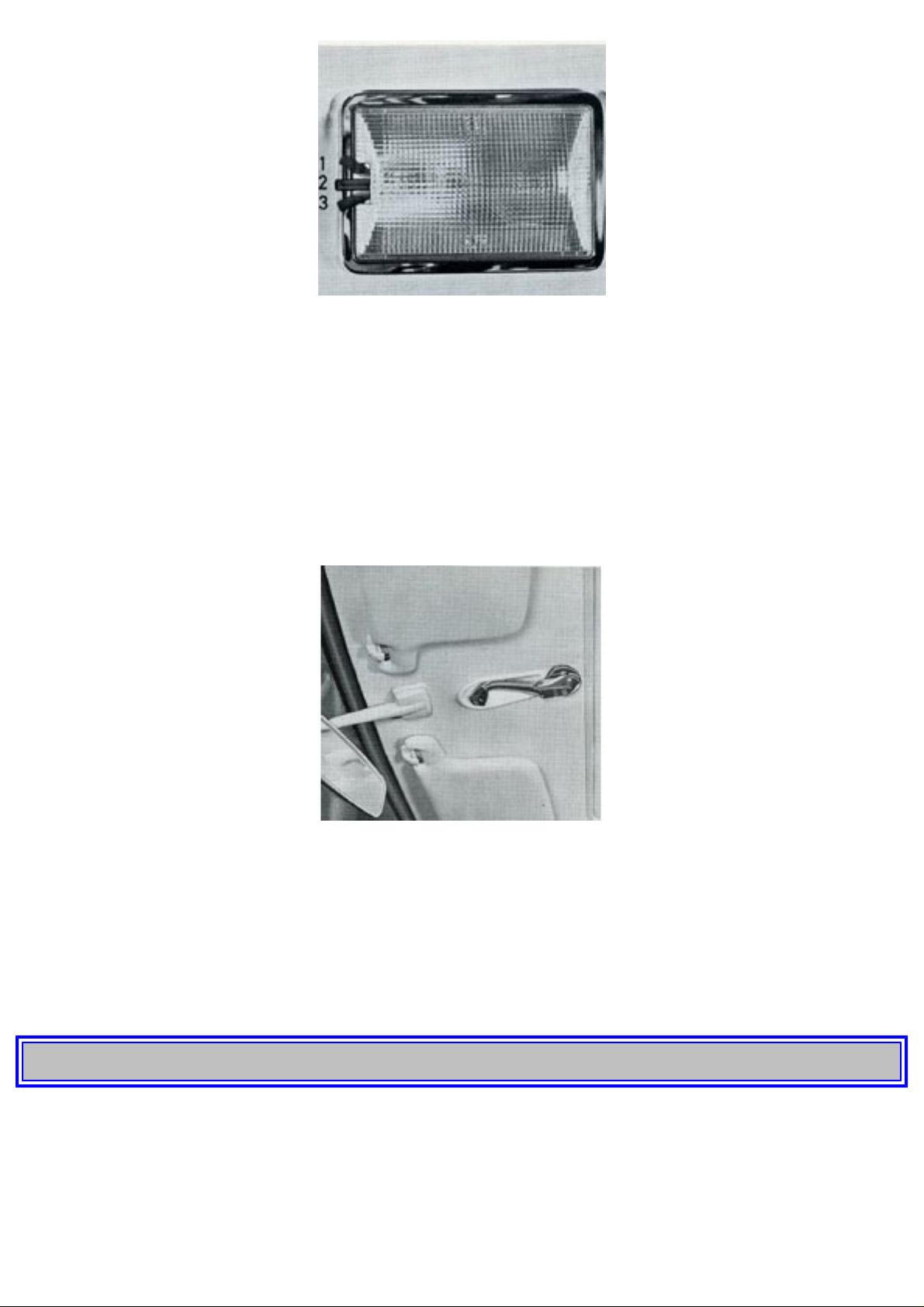
The inside rear view mirror is provided with an anti-dazzle knob at the bottom of the mirror. The
mirror is switched to anti-dazzle by pushing the knob.
The outside rear view mirrors can be adjusted sideways by moving the mirror arm and up and down
by moving the mirror itself.
http://new.volvocars.com/ownersdocs/1974/1974%20142%20144%20145/74142144145_01.htm (21 sur 32) [2013-03-14 11:43:46]
Page 26
1974 Volvo 142 144 145
Interior light
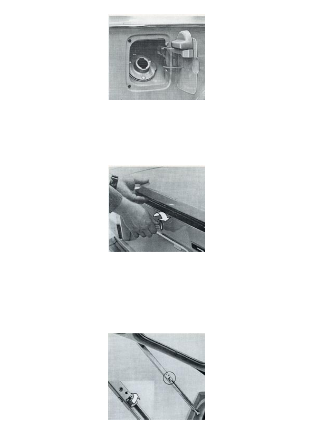
1. Lamp lights when front door is opened.
2. Lamp is always out.
3. Lamp is always on.
Ventilation window
On two-door cars, the rear side ventilation windows can be partly opened by turning the handle
upwards.
Sun-roof
Certain models are equipped with a sun-roof.
The sun-roof is opened and closed by a winding handle. When not in use, the handle is folded in the
recess in the roof between both the sun visors.
To close the sun-roof, wind it forwards fully, then wind back the handle a little and fold it into the
recess in the roof.
pg. 22 OPERATING INSTRUCTIONS
http://new.volvocars.com/ownersdocs/1974/1974%20142%20144%20145/74142144145_01.htm (22 sur 32) [2013-03-14 11:43:46]
Page 27
1974 Volvo 142 144 145
Fuel tank
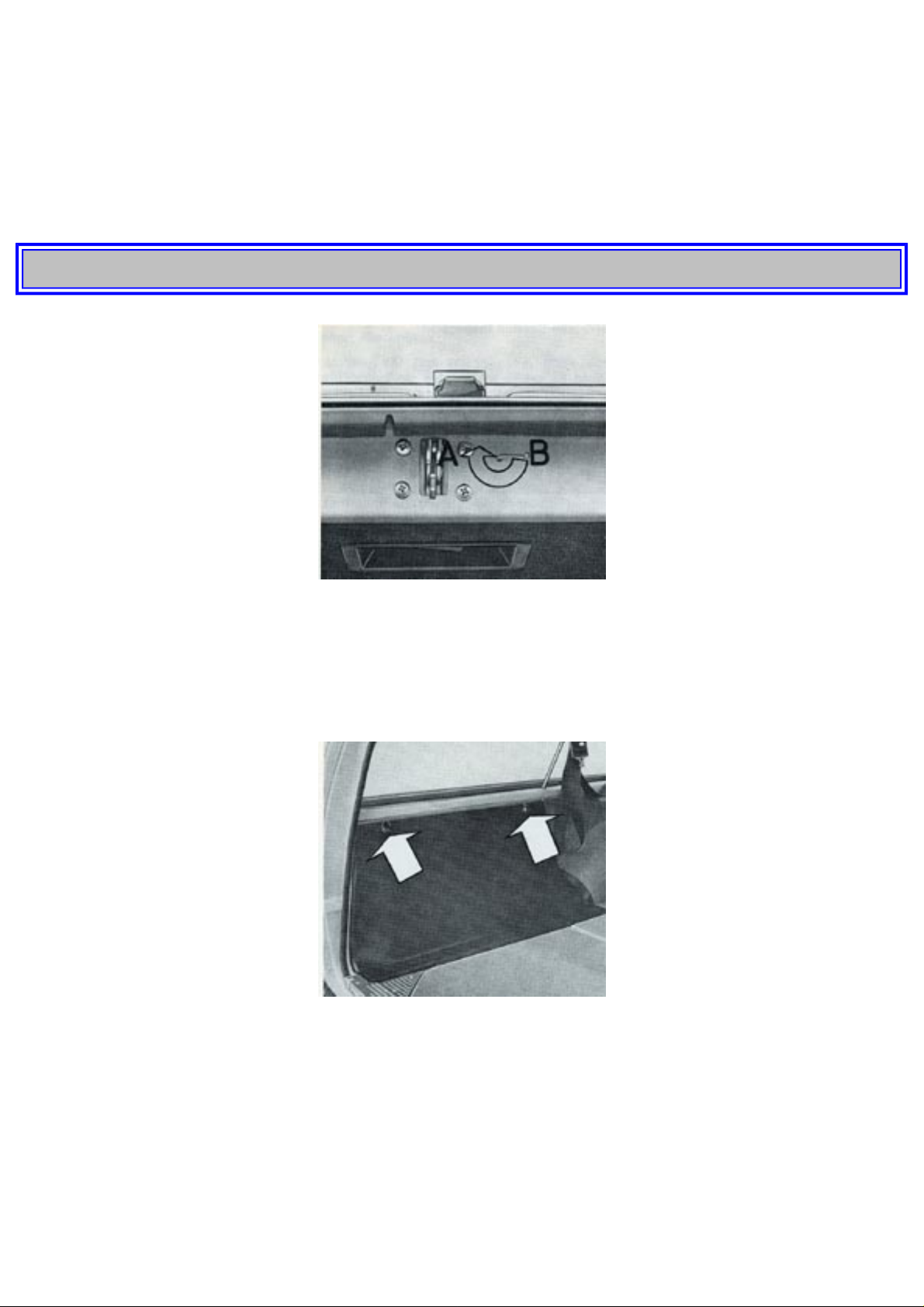
The door for the fuel tank filler cap is located on the right rear fender. When filling, it is advisable to
let the cap rest in a recess on the inside of the door, see the picture.
Note: if the tank cap is replaced, the new one should be of the non-ventilated type.
Trunk
The trunk is locked with the same key as that used for the doors. The lid is opened by turning the
handle clockwise and lifting the lid up at the same time. Note that the key must be taken out of the
lock in order to turn the knob and open the lid. The lid is balanced and will remain stationary in its
opened position.
The spare wheel is securely held in position to the left in the trunk. The jack and tool kit are stowed
with the spare wheel.
http://new.volvocars.com/ownersdocs/1974/1974%20142%20144%20145/74142144145_01.htm (23 sur 32) [2013-03-14 11:43:46]
Page 28
1974 Volvo 142 144 145
Cargo compartment 145 Station Wagon
The tailgate is opened from the outside by pushing down the lock plate. A gas spring and a lock arm
hold the tailgate in the desired open position.
To shut the tailgate, the red-marked latch on the lock arm must be pressed upwards. The tailgate can
be opened from the inside by pulling out the lock handle at the bottom. The tailgate is locked with the
same key used for the doors.
pg. 23 OPERATING INSTRUCTIONS
By turning a safety catch at the tailgate underside, it is possible to prevent it from being opened from
the inside.
Turn the catch to left position (A) and close the gate, which now can opened from the outside only.
The gate operates normally when the catch is in the right position (B).
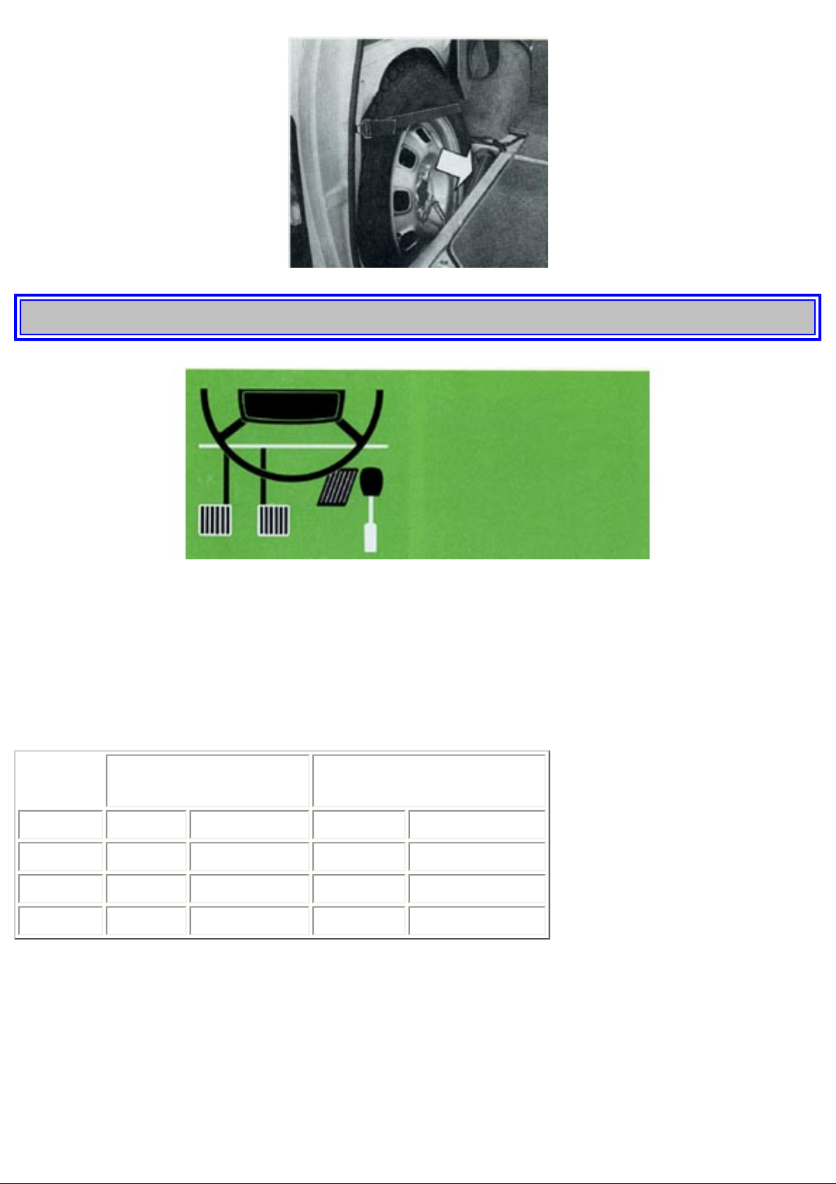
Spare wheel 145 Station Wagon
The spare wheel is stored in a well to the left of the cargo compartment underneath the floor. To get at
the wheel remove the two screws and lift the cover.
The jack is stored in this space.
http://new.volvocars.com/ownersdocs/1974/1974%20142%20144%20145/74142144145_01.htm (24 sur 32) [2013-03-14 11:43:46]
Page 29
1974 Volvo 142 144 145
pg. 24 OPERATING INSTRUCTIONS
STARTING AND DRIVING
Running-in
The maximum permissible speeds given below must not be exceeded in the beginning when the
moving parts of the car are in the process of bedding in order to achieve overall smooth function:
below the first 600 miles
(1000 km)
between 600 and 1200 miles
(1000 and 2000 km)
1st speed 20 mph (30 kmph) 30 mph (50 kmph)
2nd speed 35 mph (55 kmph) 47 mph (75 kmph)
3rd speed 50 mph (80 kmph) 60 mph (100 kmph)
4th speed 70 mph (110 kmph) 80 mph (130 kmph)
Avoid driving at low speed in high gear and using the kick-down (automatic transmission) during the
first 1200 miles (2000 km).
1500-mile Service Inspection
After 1500 miles (2500 km) the vehicle should be taken to a Volvo workshop for an inspection.
Included with the checks and adjustments then made is a change of oil in the engine, transmission and
rear axle. It is very important to ensure that the engine oil and filter change is made since during the
http://new.volvocars.com/ownersdocs/1974/1974%20142%20144%20145/74142144145_01.htm (25 sur 32) [2013-03-14 11:43:46]
Page 30

1974 Volvo 142 144 145
running-in period the engine oil usually collects a lot of impurities. Subsequent oil changes should be
made at approximately those intervals indicated in the maintenance schedule on page 42 and in the
lubricating chart at the end of the book. Before being delivered, all Volvo engines are test-run on test
benches and in the vehicles on test tracks. We are therefore assured that all clearances are satisfactory
and we thus accept no responsibility for damage caused by careless running-in (see Volvo Warranty
and Maintenance Record Book).
Your first drive
Before starting to drive your new Volvo, we would advise you to become acquainted with your car
and the various instruments and controls required for the driving. When you are seated comfortably
and can find the controls without bother you are ready to start driving.
pg. 25 OPERATING INSTRUCTIONS
Start the engine
as follows:
1. Enter the car and fasten the seat belts. If this vehicle is equipped with an ignition interlock system,
the engine can not be started unless the driver and front seat passenger have fastened their seat belts.
The belts must be fastened after the occupant(s) are seated and before turning the key to the starting
position. The seat belt reminder light and buzzer are actuated and the starter will not engage if this
sequence is not followed. (See combined ignition switch and steering wheel lock,
page 8).
2. Check that the parking brake is on and the gear lever is in neutral (position N or P. autom.
transmission).
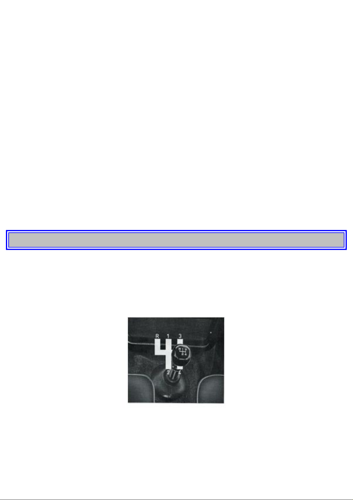
3. Always make a habit of depressing the clutch pedal until the engine starts.
4. Turn the ignition key to the starting position. Release the key as soon as the engine has started.
5. Avoid repeated short attempts to start. (In the case of each new attempt, the cold start injector
functions and causes fuel to be injected into the inlet duct).
Instead, allow the starter to operate for a rather long time (not more than 15-20 seconds, however)
each time.
Do not race the engine up to high speed immediately after starting from cold.
If the engine does not start at once, press the throttle approx. half way down and keep it there until the
engine starts.
6. If this vehicle is equipped with an ignition interlock system and the seat belt reminder light and
buzzer actuate after the engine has started, even though the seat belts are fastened, it is an indication
that the belt interlock control is out of sequence, and the starter will not engage should the engine
stop. In this case, release and refasten the front seat belts at each occupant position to turn off the light
and buzzer (see seat belt reminder light,
page 14).
Note: If the vehicle is parked on a steep incline the seat belts cannot be pulled out and, if the vehicle
is equipped with an Ignition Interlock System, the engine can not be started as long as either front seat
is occupied. If this occurs, or of the Interlock System malfunctions, open the fuse box cover (see
page
60) and remove fuse No. 9. This will allow the engine to be started in an emergency. While fuse No. 9
is removed, the seat belt reminder light will remain lit, even if the seat belts are fastened. When the
car is on level ground reinstall the fuse and fasten seat belts or see a Volvo Dealer to have the
http://new.volvocars.com/ownersdocs/1974/1974%20142%20144%20145/74142144145_01.htm (26 sur 32) [2013-03-14 11:43:46]
Page 31
1974 Volvo 142 144 145
interlock system checked if malfunctioning.
Starting in garage
Before starting your car in a garage, always open the garage doors. The exhaust gases from the engine
contain carbon monoxide gas which is poisonous and particularly dangerous since it is invisible and
odorless.
Warming up the engine
Experience has shown that engines in vehicles used for frequent stopping and starting are subject to
abnormally rapid wear. The reason for this is that the engine is not given a chance to reach its normal
working temperature. When the engine is cold, it should just be taken up to its normal working
temperature as quickly as possible. Therefore, do not idle the engine too long but start driving on light
throttle as soon as the oil pressure light has gone out.
Driving with the trunk lid open
While driving with the trunk lid partly or fully open, exhaust gases can be sucked into the car through
the trunk. Normally, this involves no risk to the passengers. However, the following advice should be
followed on such occasions:
1. Keep all windows closed.
2. Set the fresh air and defroster controls to the fully-opened position and the fan switch to full speed.
pg. 26 OPERATING INSTRUCTIONS
SHIFTING
The transmission is synchronized on all forward gears. If synchronization is to function satisfactorily,
the clutch pedal must be fully depressed. Never let the engine drag in high gear. Shift down in good
time.
Floor-mounted shift lever
Shifting with a floor-mounted shift lever is quite conventional and the different shift positions are
shown in the picture above.
http://new.volvocars.com/ownersdocs/1974/1974%20142%20144%20145/74142144145_01.htm (27 sur 32) [2013-03-14 11:43:46]
Page 32
1974 Volvo 142 144 145
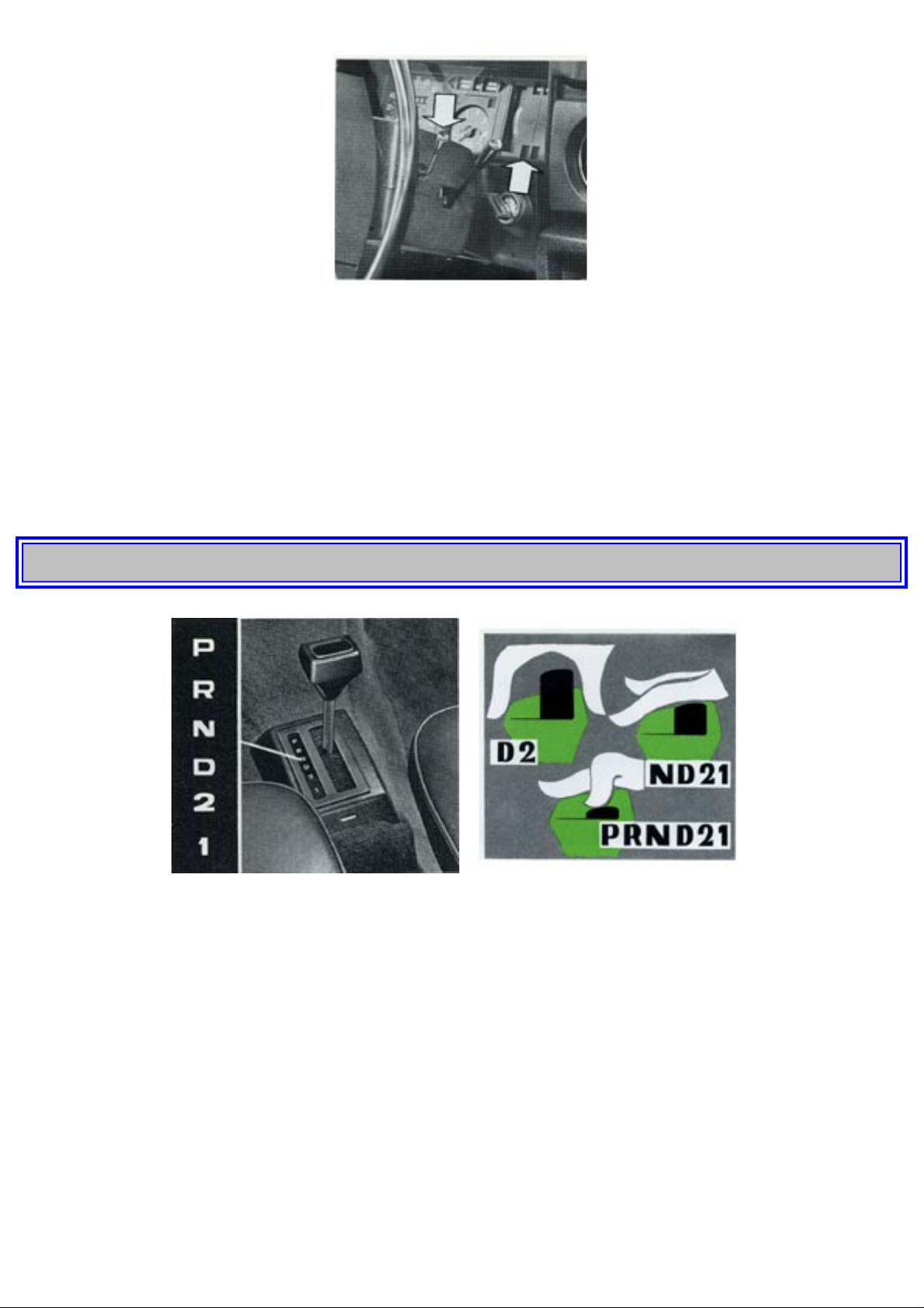
Overdrive
The overdrive, which can be engaged on fourth gear, is operated by a lever to the right under the
steering wheel. Moving the lever downwards engages and upwards disengages the overdrive. No extra
operation of the clutch pedal or accelerator is normally necessary but engagement of overdrive is
facilitated if the accelerator position is maintained steady. When disengaging the overdrive, light
pressure on the clutch pedal helps to make this operation more smooth.
The overdrive should not be used at speeds below 40 mph (60 kmph).
pg. 27 OPERATING INSTRUCTIONS
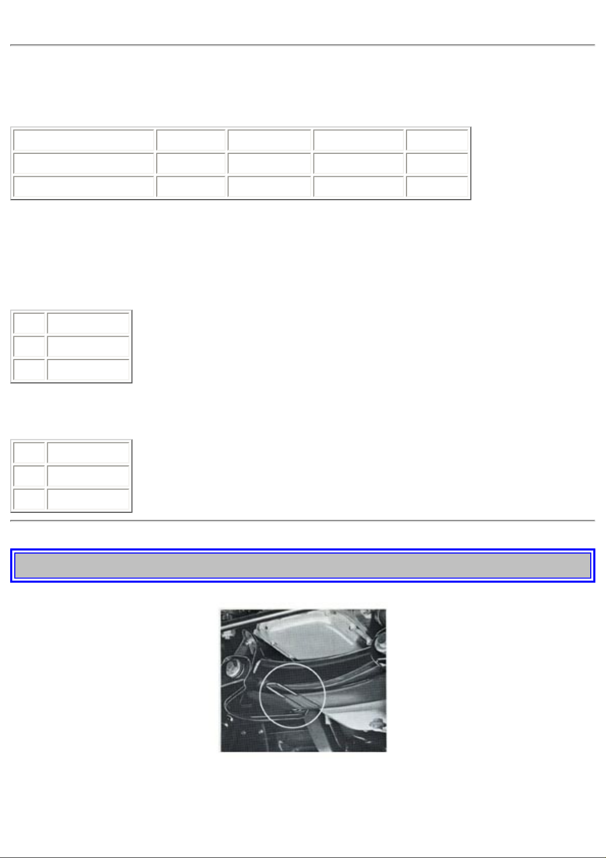
Automatic transmission
The selector lever positions are marked on the console next to the selector lever.
P= Parking
R= Reverse
N=Neutral
D=Driving
1
2= Low gear
The selector lever can be moved freely between positions D and 2 while the other positions are
provided with a gate which is "opened" with the button on the knob of the selector lever.
http://new.volvocars.com/ownersdocs/1974/1974%20142%20144%20145/74142144145_01.htm (28 sur 32) [2013-03-14 11:43:46]
Page 33

1974 Volvo 142 144 145
To change from D and 2 to positions N or 1 press lightly on the button with the palm of the hand.
With the button in this position the selector lever can thus be moved between the four positions 1, 2,
D and N
Changing to positions R and P requires more force on the button with, e.g. the thumb. This
manipulation is also required to move the lever out of P position. In other words, when the button is
pushed down fully, the selector lever can be moved freely between all the shift positions.
2-position
In position 2 the transmission can shift up or down automatically between 1st and 2nd gear.
In this position there is no shifting up to 3rd gear.
2 position can be used to obtain immediate downshifting (to 2nd gear) and also when shifting up from
2nd to 3rd gear is not desired, for example, at the following times:
● during certain types of highway driving
● during crawling town driving
● when driving in hilly country
● when overtaking
● in order to increase engine braking
Do not select 2 position for speeds exceeding 70 mph (110 kmph).
1-position
With 1 position there is automatic downshifting but no upshifting. If 1 position is selected at high
speed, 2nd gear is engaged. It is only when the speed has dropped to about 6 mph (10 kmph) that 1st
gear engages. The 1st gear can also be engaged by kick-down below about 30 mph (50 kmph). If you
want to drive in 1st gear without intending to shift up, use 1 position.
Do not choose 1 position for speeds exceeding 70 mph (110 kmph).
pg. 28 OPERATING INSTRUCTIONS
Kick-down
When the accelerator pedal is depressed past full throttle position, kick-down is obtained, that is, there
is an immediate shifting down to the next lower gear. As soon as a maximum speed for this gear has
been reached or if the accelerator pedal is eased from the kick-down position, automatic shifting takes
places to the next higher gear.
Driving
Starting the engine
Move the selector to P or N. The starting switch will be put out of function if the selector is moved to
any of the other positions.
Important
Do not select P or R when the car is moving.
Do not select D, 2, 1 or R at an engine speed higher than idling when the car is stationary.
P position may only be selected when the car is standing still.
http://new.volvocars.com/ownersdocs/1974/1974%20142%20144%20145/74142144145_01.htm (29 sur 32) [2013-03-14 11:43:46]
Page 34
1974 Volvo 142 144 145
STANDARD TRANSMISSION
Recommended max. and min. speeds mph (kmph) for the different gears
Car Model 1st gear 2nd gear 3rd gear 4th gear
142, 144, 145 0-35 (0-55) 10-55 (20-85) 20-80 (30-125) 25- (40-)*
142, 144 with overdrive 0-30 (0-50) 10-50 (20-80) 20-75 (30-120) 25- (40-)*
*) 40 mph (60 kmph) with overdrive engaged.
AUTOMATIC TRANSMISSION
Gear speeds at full throttle, kick-down, mph (kmph)
Gear 142, 144, 145
1-2 37 (60)
2-3 75 (110)
Max. speed when kick-down downshifting, mph (kmph)
Gear 142, 144, 145
3-2 63 (100)
3-1 30 (50)
pg. 29 OPERATING INSTRUCTIONS
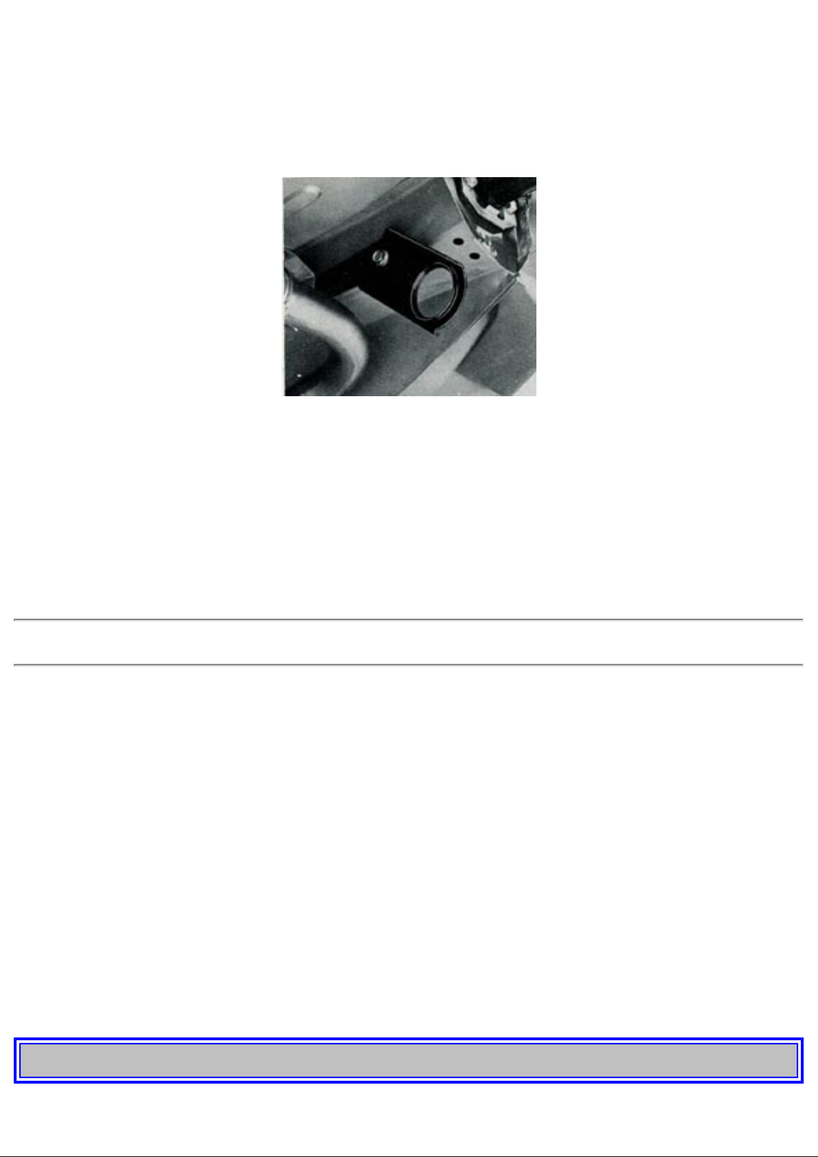
Emergency towing (pulling)
The line should be attached to one of the eyelets installed underneath the car.
http://new.volvocars.com/ownersdocs/1974/1974%20142%20144%20145/74142144145_01.htm (30 sur 32) [2013-03-14 11:43:46]
Page 35
1974 Volvo 142 144 145
At the front, the eyelet is situated at the right-hand side (above picture) on the front axle member, and
the rear eyelet on the right side (below picture). During pulling, the line should be kept stretched to
avoid unnecessary jerking.
The bumper must not be used for lifting (as for towing or transportation by fork lifts etc) as it
incorporates an energy absorption system.
Towing, automatic transmission
If necessary, your car can be towed with the selector lever in position N, providing that the
transmission is properly adjusted and that the oil level is correct. The maximum permissible speed
when towing is 20 mph (30 kmph) and the longest distance your car ought to be towed is 20 miles (30
km). If the car has to be towed longer than this or if you suspect that there is some fault in the
transmission, the rear wheels should be raised or the propeller shaft disconnected in order to avoid
possible damage to the transmission.
Check your state laws on towing!
Starting by pulling
The towing car should start smoothy and be driven at even speed in 2nd gear.
Standard transmission: Engage 3rd or 4th gear and gradually release the clutch pedal. Once the
engine starts running, depress the clutch pedal.
Attention!
Remember that a car with automatic transmission can not be started by pulling.
If your car can not be started because of a flat battery, an assist battery with cables must be used
instead.
NOTE. Always connect a plus cable from the assist starter battery to the plus pole on the car
battery and the minus cable to the minus pole.
pg. 30 OPERATING INSTRUCTIONS
http://new.volvocars.com/ownersdocs/1974/1974%20142%20144%20145/74142144145_01.htm (31 sur 32) [2013-03-14 11:43:46]
Page 36

1974 Volvo 142 144 145
Trailer hauling
Driving with a trailer involves no particular difficulties provided you follow the recommendations of
the trailer manufacturer concerning equipment and loading.
The hitch must be approved for trailers of at least 2000 lbs gross loaded weight.
Your Volvo dealer will certainly give you tips about suitable hitches for your Volvo.
The lighting for the trailer and car as well as the car's rear view mirrors must conform to the
requirements of the federal and local authorities.
The load in the trailer should be so distributed that there is a certain pressure on the car's hitch tongue,
but max. 160-200 lbs.
Remember to increase the rear wheel tire pressure when the hitch load approaches the maximum
allowed.
However, do not exceed the maximum permitted load (see
page 76).
The maximum speed when hauling a trailer is 75 mph.
IMPORTANT ABOUT BRAKING
When you drive your car in the rain or through pools of water, also when washing the car, water can
splash on the brake discs and linings and thereby alter the friction properties of the brake linings so
that a certain delay in braking effect can sometimes be noticed.
If you drive some distances in rain or slush, you should depress the brake pedal lightly now and
again in order to heat up the brake linings and remove the moisture on them. This should also be done
after washing the car and after starting in very damp weather.
When the brake servo is not functioning, e.g., on rolling the car with the engine switched off, pressure
on the brake pedal must be 3 to 4 times greater if the same braking effect is to be achieved as when
the servo is functioning.
Note that the brake pedal travel will be short and stiff.
If one of the brake circuits should stop functioning (the red warning lamp F, see
page 6. lights) double
pressure on the brake pedal is required in order to achieve approx. 80% of the normal braking effect.
About 50% braking effect is achieved with normal pedal pressure. Note that here the pedal stroke
will be long but the pedal will then feel stiff and hard in the braking position. The car should be
taken as soon as possible to a workshop for a check on the brake system.
Top of Page
http://new.volvocars.com/ownersdocs/1974/1974%20142%20144%20145/74142144145_01.htm (32 sur 32) [2013-03-14 11:43:46]
Page 37
1974 Volvo 142 144 145
1 9 7 4
VOLVO
142 144 145
pg. 31 TECHNICAL DESCRIPTION
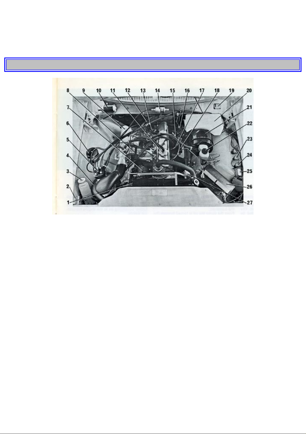
ENGINE COMPARTMENT
1. Radiator
2. Voltage regulator
3. Expansion tank
4. Air cleaner
5. Air-fuel control unit
6. Carbon canister, evaporative control system
7. Alternator
8. Idle adjust screw
9. Inlet duct
10. Windshield wiper motor
11. Oil filler cap
12. Oil dipstick, automatic transmission
13. Injector
14. Fuel filter
15. Distributor
16. Ignition coil
17. Oil dipstick, engine
18. Starter motor
19. Data plate
20. Washer fluid container
21. Brake power assist
22. Brake fluid container
23. Relay for fuel pump
24. Main relay for fuel injection
25. Switch relay, upper/lower beams
26. Battery
http://new.volvocars.com/ownersdocs/1974/1974%20142%20144%20145/74142144145_02.htm (1 sur 9) [2013-03-14 11:43:55]
Page 38
1974 Volvo 142 144 145
27. Steering
pg. 32 TECHNICAL DESCRIPTION
ENGINE
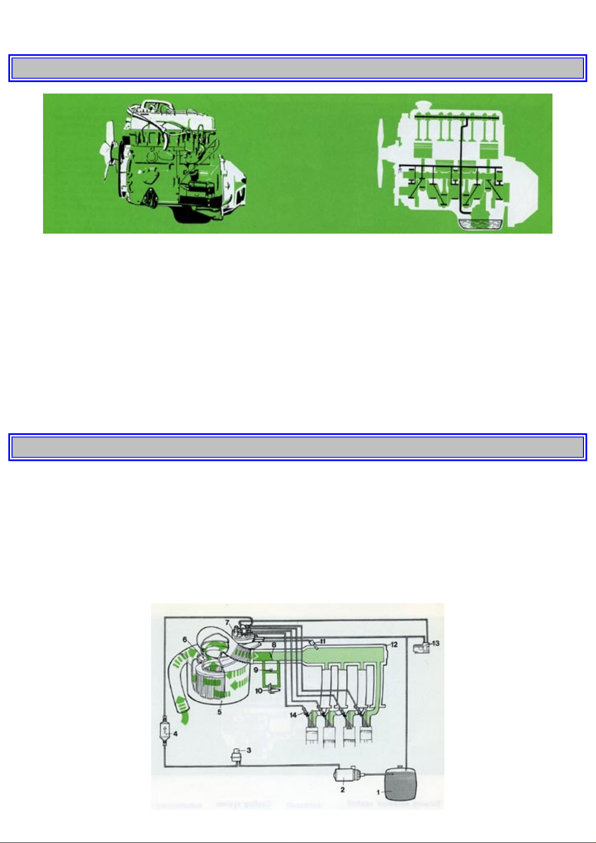
The engine is a four-cylinder, water-cooled unit with overhead valves.
The cylinder block is made of special alloy cast iron and is cast in a single unit. The cylinder liners, which are surrounded by
cooling jackets, are machined directly in the block. The cylinder head has separate inlet and exhaust ports, one for each
valve.
Lubricating system
Engine lubrication is taken care of by a gear pump located under the crankshaft in the sump. The pump is driven by a gear
from the camshaft.
From the pump the oil is forced through the oil filter and then along oilways to the various lubricating points. A relief valve
is built into the oil filter and prevents the oil pressure from reaching excessively high values. The oil filter is of the full-flow
type, that is, all the oil passes through the filter before continuing on to the engine lubricating points.
pg. 33 TECHNICAL DESCRIPTION
Fuel system
The engine is provided with a fuel injection system, called the Cl-system. Cl stands for Continuous Injection.
The system has no mechanical guidance. It has two systems: the air system and the fuel system. The idea is to measure the
inducted air quantity and then let it determine the fuel quantity to be injected.
The air system comprises: air intake, air cleaner (5), air flow sensor (6) throttle (8), auxiliary air valve (10) and intake
manifold (12). The air is cleaned, measured, controlled and directed by the system to the engine cylinders.
The fuel system comprises: fuel pump (2), fuel accumulator (3), fuel filter (4), fuel distributor (7), control pressure regulator
(13), injectors (14) and a cold start injector (11) with a thermal time switch.
http://new.volvocars.com/ownersdocs/1974/1974%20142%20144%20145/74142144145_02.htm (2 sur 9) [2013-03-14 11:43:55]
Page 39
1974 Volvo 142 144 145
Operation diagram, fuel system
1 Fuel tank
2 Fuel pump
3 Fuel accumulator
4 Fuel filter
5 Air cleaner
6 Air flow sensor
7 Fuel distributor
8 Throttle
9 Idle adjustment screw
10 Auxiliary air valve
11 Cold start injector
12 Intake manifold
13 Control pressure regulator
14 Injector
pg. 34 TECHNICAL DESCRIPTION
Exhaust emission control
Your Volvo is equipped with exhaust emission control, that is, a system which as a result of better mixing and distributing
of fuel and air provides a more complete combustion and thereby cleaner exhaust gases. The exhaust emission control is
provided by the fuel injection system.
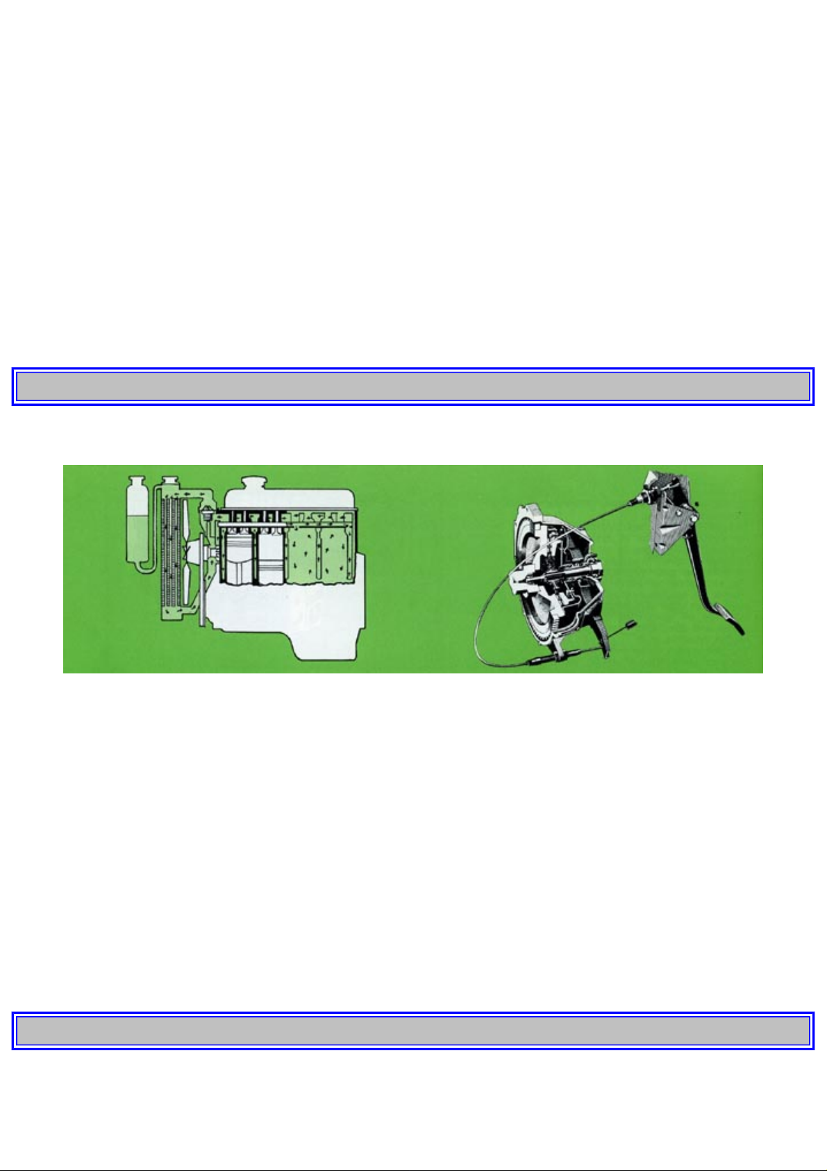
Cooling system
The cooling system is of the sealed pressure type and incorporates a circulation pump. An expansion tank prevents air from
circulating with the coolant as this would cause corrosion in the cooling system. The fan is driven via a slip coupling which
permits a max. fan speed of approx. 2500 rpm, resulting in a lower noise level.
POWER TRANSMISSION
Clutch
The function of the clutch is to transmit power from the engine to the transmission. The clutch is of the single dry plate type.
Pressure on the pressure plate is obtained from a diaphragm spring which in its turn is controlled by the clutch pedal via the
throw-out yoke.
pg. 35 TECHNICAL DESCRIPTION
http://new.volvocars.com/ownersdocs/1974/1974%20142%20144%20145/74142144145_02.htm (3 sur 9) [2013-03-14 11:43:55]
Page 40
1974 Volvo 142 144 145
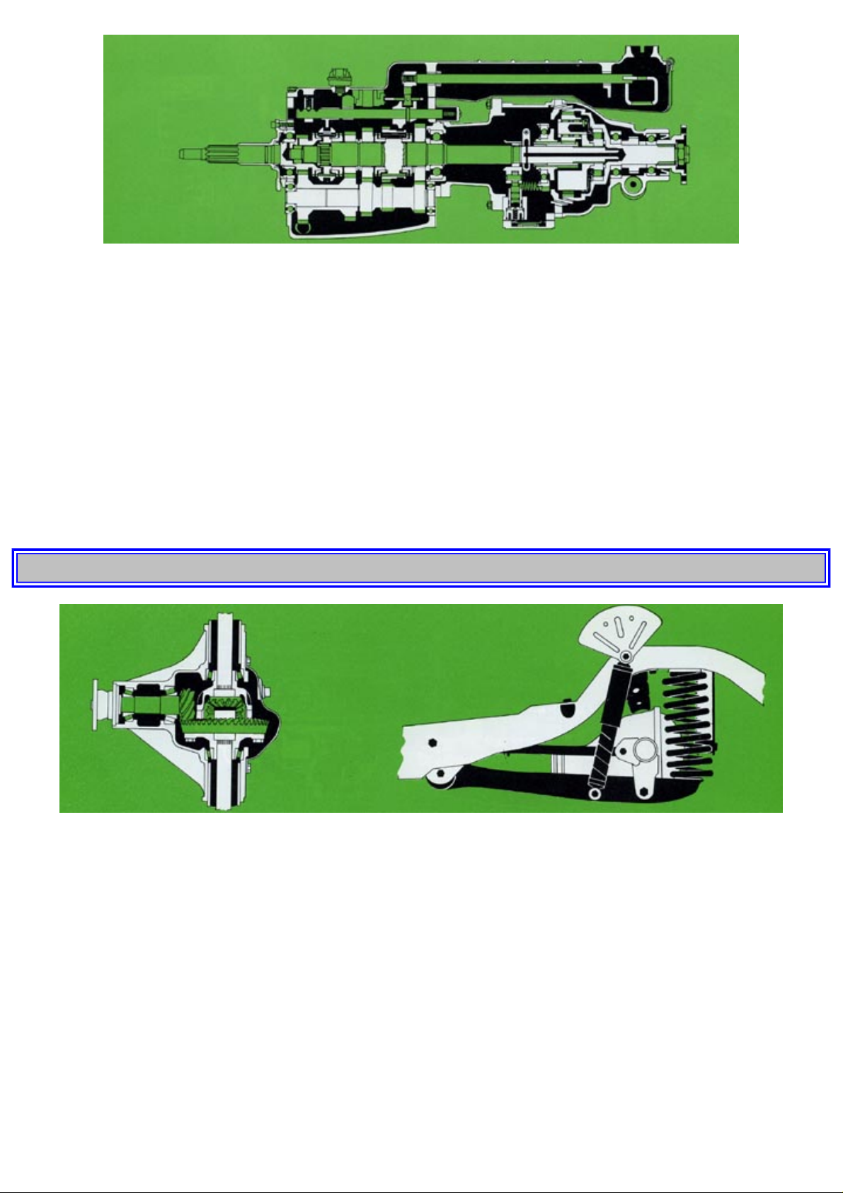
Transmission
The transmission has synchromesh on all forward gears. Since it is equipped with helical gears and the gear lever is rubberinsulated, good sound insulation is obtained.
Automatic transmission
As an alternative, your Volvo can be equipped with a BW 35 automatic transmission. In principle it consists of two main
components - a hydraulic torque converter and a hydraulically operated epicyclic gearbox with a control system. The
converter serves as a clutch and as an extra gear between engine and transmission.
Overdrive
As an alternative the Volvo Grand Luxe can be equipped with an overdrive. With the overdrive, it is possible to reduce
engine speed while maintaining road speed. This is less wearing on the engine and reduces fuel consumption at the same
time.
pg. 36 TECHNICAL DESCRIPTION
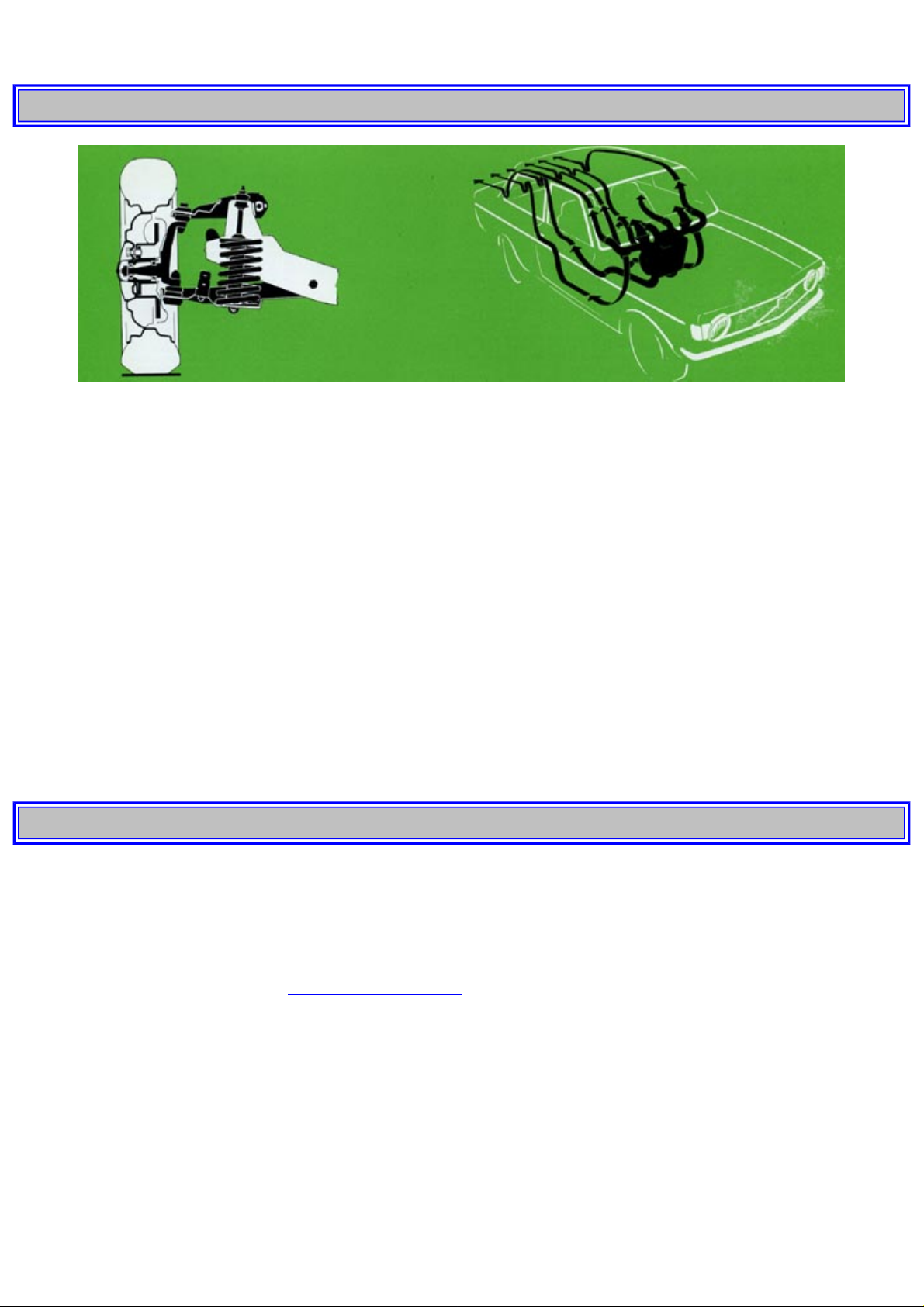
Final drive
Engine torque is transmitted via the propeller shaft to the rear wheels through the final drive. The final drive is of the hypoid
type, that is, the drive pinion lies below the center line of the drive shafts.
Limited slip
A limited slip differential can be obtained as extra equipment. A rear axle with a limited slip automatically transmits the
tractive power to the wheel having the best road grip when a wheel begins to spin. Except for the differential, the rear axle is
similar in design to a conventional rear axle.
Do not rotate a jacked-up rear wheel if the other rear wheel is still on the ground. Due to the differential, there is still drive
on the wheel in contact with the ground. Rotating the jacked-up rear wheel would thus move the other rear wheel and
may cause the car to topple off the jack.
Rear axle
The rear axle is carried on two trailing arms the front ends of which are bolted to the body. The rear axle casing is secured to
the trailing arms by means of levers. Two torque rods are journalled on the casing and the body. A "Panhard" rod prevents
http://new.volvocars.com/ownersdocs/1974/1974%20142%20144%20145/74142144145_02.htm (4 sur 9) [2013-03-14 11:43:55]
Page 41
1974 Volvo 142 144 145
lateral movement of the body and rear axle in relation to each other.
pg. 37 TECHNICAL DESCRIPTION
FRONT END AND STEERING
Front end
The front suspension units are mounted on a strong box member. The member is bolted firmly to the front section of the
body. The front wheels are journaled in tapered roller bearings. The front springs consist of coil springs in which telescopic
shock absorbers are fitted. The car is provided with stabilizers secured to the lower control arms and to the body.
Steering
The steering is of the cam-and-roller type. Movements of the steering wheel are transmitted via the worm on the steering
column to the roller on the pitman shaft, which in turn operates the wheels through a linkage system.
Some Volvo models are available with power steering.
HEATING SYSTEM
The heating system is a combined warm and fresh air system. The incoming fresh air is blown by a fan through the cell
system of the element into the vehicle. By means of the various ventilation controls, the fresh air can be warmed up and
directed to suitable places in the car.
From there the air passes out of the car through a number of extractor vents under the rear window. This system provides
good ventilation in the vehicle as well as effective demisting of the tailgate window and side windows.
pg. 38 TECHNICAL DESCRIPTION
ELECTRICAL SYSTEM
The electrical system is of the 12-volt type and is equipped with a voltage-regulated alternator. The starter motor is operated
by the ignition switch. This switch is also the main switch for the rest of the electrical system. The headlights, parking lights
and interior lighting, however, are not wired via the ignition switch so they can be switched on and off without the ignition
key being in position.
Concerning replacement of bulbs, see
pages 57, 58, 59 and 60.
Note: The Bulb Integrity Sensor is designed for a certain current flow and it is therefore not possible to make extra current
taps for auxiliary tail lights and stop light for trailers etc at any place in the electrical system. These wires should therefore
be directed to the firewall where the possibilities exist to make the electrical connections.
Wiring diagram, 142, 144, 145
1. Battery, 12V, 60 Ah
2. Connection box
3. Ignition switch
4. Ignition coil
5. Distributor, firing order 1-3-4-2
http://new.volvocars.com/ownersdocs/1974/1974%20142%20144%20145/74142144145_02.htm (5 sur 9) [2013-03-14 11:43:55]
Page 42

1974 Volvo 142 144 145
6. Spark plugs
7. Starter motor
8. Alternator
9. Voltage regulator
10. Fuse box
11. Headlight switch
12. Bulb integrity sensor
13. Relay for upper and lower beams and headlight flasher
14. Upper beam
15. Lower beam
16. Position light ,5W
17. Tail light, 5W
18. Side marker light, 5W
19. License plate light, 2x5W
20. Stop light switch
21. Stop light, 32 cp
22. Contact on transmission, M40, M41
23. Contact on transmission, BW35
24. Back-up light, 32 cp
25. Flasher unit
26. Turn signal switch
27. Hazard warning signal switch
28. Front turn signal, 32 cp
29. Rear turn signal, 32 cp
30. Connection at instrument
31. Connection at instrument
32. Brake failure pilot light, 1.2W
33. Connection at instrument
34. Tachometer
35. Thermometer
36. Fuel gauge
37. Voltage stabilizer
38. Turn signal pilot light, 1.2W
39. Diode
40. Upper beam pilot light, 1.2W
41. Bulb Integrity Sensor warning light
42. Charging pilot light, 1.2W
43. Parking brake pilot light, 1.2W
44. Choke pilot light, 1.2W
45. Oil pressure pilot light, 1.2W
46. Contact, passenger's seat
47. Contact, driver's seat
48. Parking brake contact
49. Choke control contact (certain markets only)
50. Temperature gauge
51. Oil pressure guard
52. Brake failure contact
53. Starter cut-out relay
54. Fuel level gauge
55. Horn
56. Horn ring
57. Windshield wiper-washer switch
58. Windshield wiper
59. Windshield washer
60. Blower switch
61. Blower
http://new.volvocars.com/ownersdocs/1974/1974%20142%20144%20145/74142144145_02.htm (6 sur 9) [2013-03-14 11:43:55]
Page 43

1974 Volvo 142 144 145
62. El. heated rear window switch
63. El. heated rear window
64. Clock
65. Cigarette lighter
66. Instrument lighting rheostat
67. Instrument lighting, 2W
68. Control panel lighting, 1.2W
69. Gear selector lighting, 1.2W
70. Glove compartment contact
71. Glove compartment light, 2W
72. Interior light, 10W
73. Door contact, driver's side
74. Door contact, passenger's side
75. Relay for headlight wiper (certain markets only)
76. Seat-ignition belt interlock unit
78. Safety belt pilot light, 1.2W
79. Safety belt contact, passenger's seat
80. Safety belt contact, driver's seat
81. Junction
82. Overdrive switch, M41
83. Overdrive contact on transmission M41
84. Overdrive solenoid on transmission M41
85. Overdrive pilot lamp, 1.2W
87. Headlight wiper (certain markets only)
89. Heating element with thermostat, driver's seat, 30W
90. Heating element, driver's seat, 30W
91. Light warning buzzer
97. Fuel pump relay
98. Main relay, fuel injection
99. Cold start injector
100. Thermal time switch
101. Control pressure regulator
102. Fuel pump
103. Air flow sensor
104. Rear interior light, 10W (only 145)
105. Rear door contact (only 145)
106. Rear window wiper (only 145)
107. Rear window washer (only 145)
108. Rear window wiper/washer switch (only 145)
109. Auxiliary air valve
NOTE: Variations may occur.
pg. 39 TECHNICAL DESCRIPTION
http://new.volvocars.com/ownersdocs/1974/1974%20142%20144%20145/74142144145_02.htm (7 sur 9) [2013-03-14 11:43:55]
Page 44
1974 Volvo 142 144 145
pg. 40 TECHNICAL DESCRIPTION
BRAKES
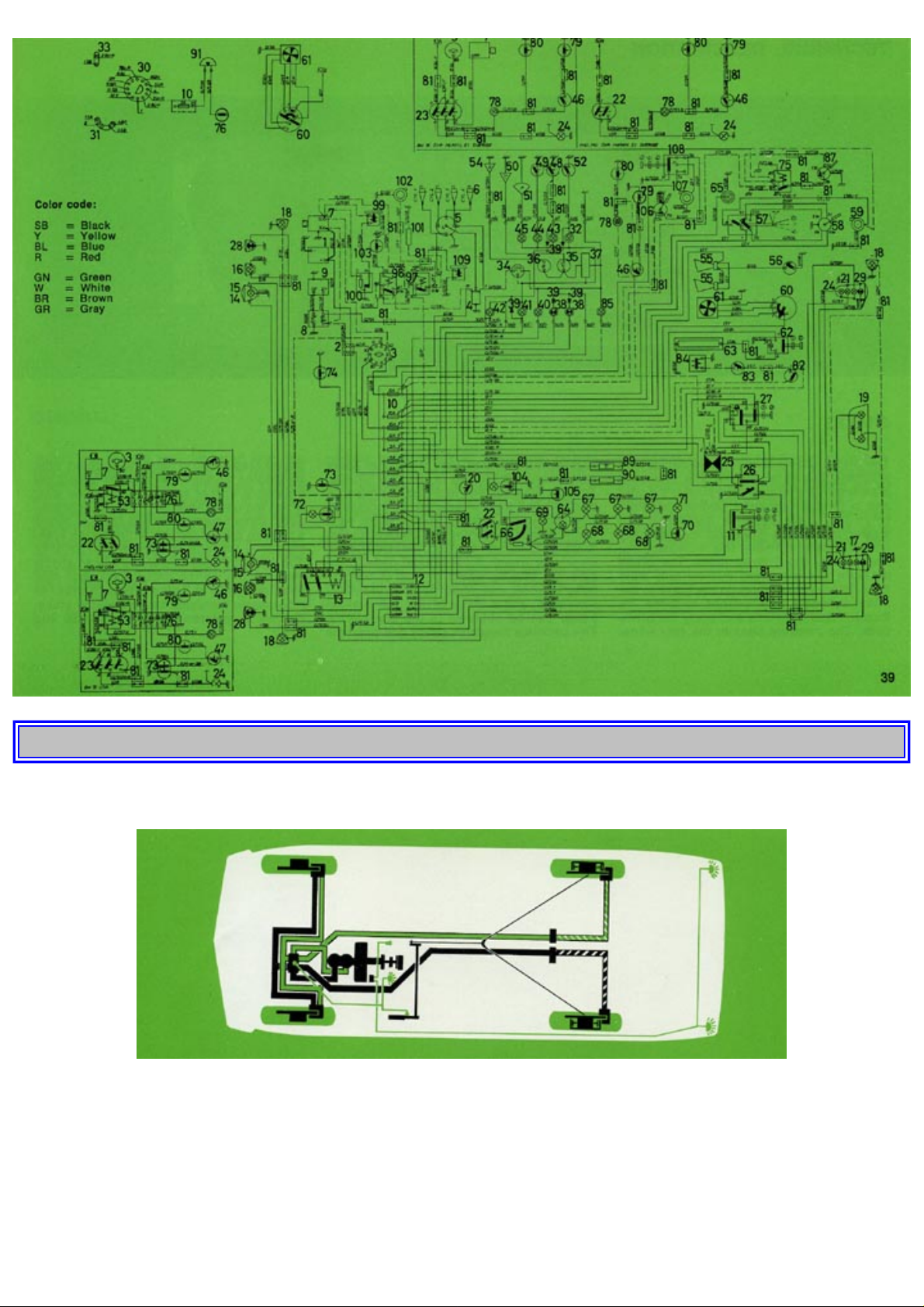
The brake system is of the two-circuit type with disc brakes all round. The system is provided with a tandem-type master
cylinder and a directly-operating booster cylinder. When the brake pedal is depressed, the master cylinder is operated
mechanically via the booster cylinder, this increasing the pedal force about three times. The brake pressure is transmitted
hydraulically from the master cylinder through the brake to the wheel cylinders. The pistons in these are then pressed
outwards and apply the brake pads. The pressure lines to the rear wheel brakes are provided with a reducer valve which
prevents locking of the rear wheels. The principle of the two-circuit system is that both the front wheels are connected to one
rear wheel, that is, should there be a failure in one of the circuits, there is always braking power on both front wheels and the
http://new.volvocars.com/ownersdocs/1974/1974%20142%20144%20145/74142144145_02.htm (8 sur 9) [2013-03-14 11:43:55]
Page 45

1974 Volvo 142 144 145
other rear wheel. So at normal pedal pressure the braking effect of one of the circuits is 50 %, but when pedal pressure is
increased, about 80% of the full braking power can be obtained in the one circuit. This provides maximum safety and
prevents lateral dragging and rear-end lurching. With the engine stopped, the booster assists the braking a further two or
three times after which the pedal pressure must be increased about three times as much in order to obtain a braking power
corresponding to the braking power available with the engine running. The parking brake operates the rear wheels
mechanically as the brake discs have also been designed as brake drums in order to incorporate the shoes for the parking
brake. For brake maintenance, see
page 50 and 61.
Top of Page
http://new.volvocars.com/ownersdocs/1974/1974%20142%20144%20145/74142144145_02.htm (9 sur 9) [2013-03-14 11:43:55]
Page 46

1974 Volvo 142 144 145
1 9 7 4
VOLVO
142 144 145
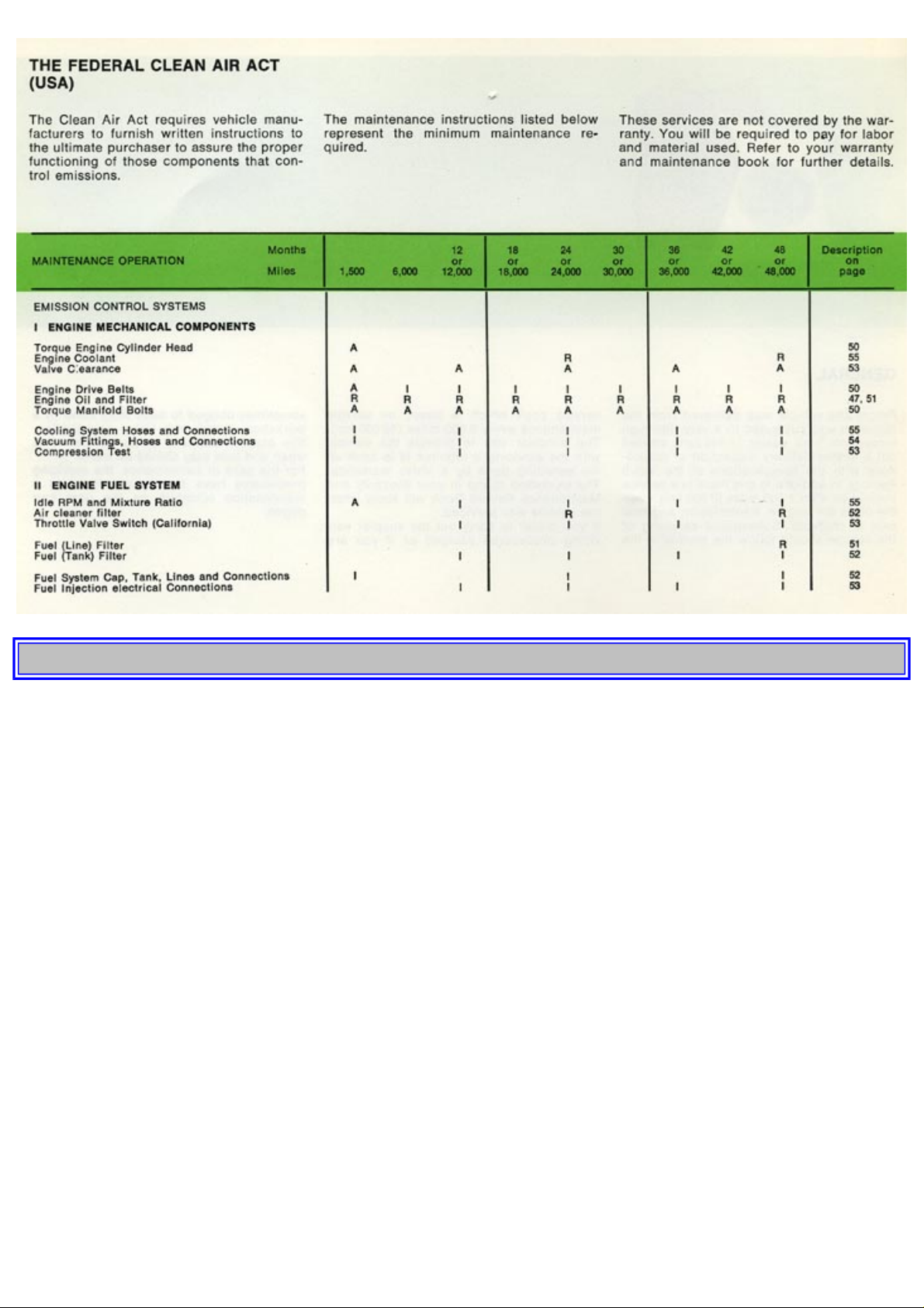
pg. 41 SERVICING
GENERAL
Before the vehicle was delivered from the factory it was subjected to a very thorough inspection. Your dealer, in his turn,
carried out a further delivery inspection in accordance with the specifications of the Volvo Factory. In addition to this there is
a service inspection after 1,500 miles (2,500 km) when the oil in the engine, transmission and rear axle is changed. Subsequent
servicing of the vehicle should follow the routine in the service book which is based on service maintenance every 6,000 miles
(10,000 km). The simplest way to provide the vehicle with the servicing it requires is to have all the servicing done by a Volvo
workshop. The workshop stamp in your Warranty and Maintenance Record Book will show when the vehicle was serviced.
If you prefer to carry out the simpler servicing procedures yourself or if you are sometimes obliged to have them done by a
workshop outside the Volvo organization, this chapter contains same advice as to when and how they should be made. For the
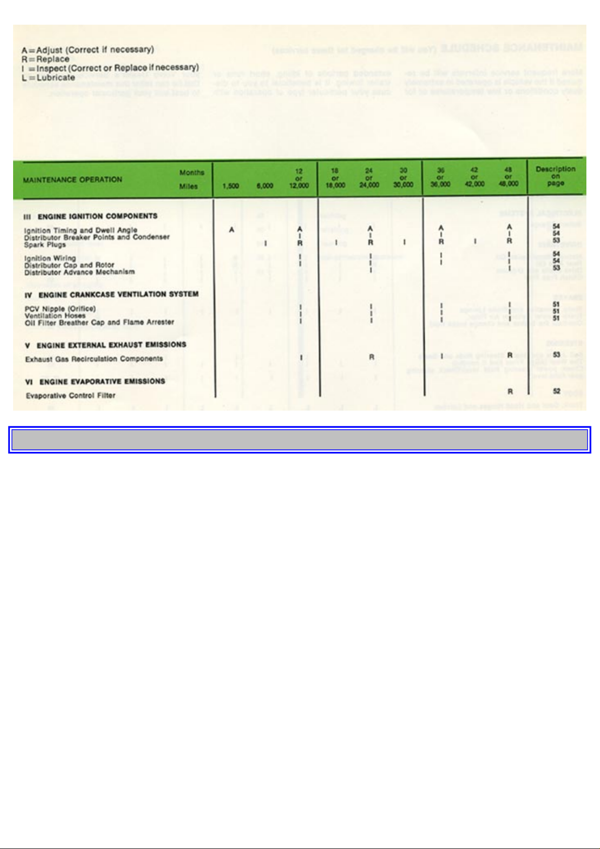
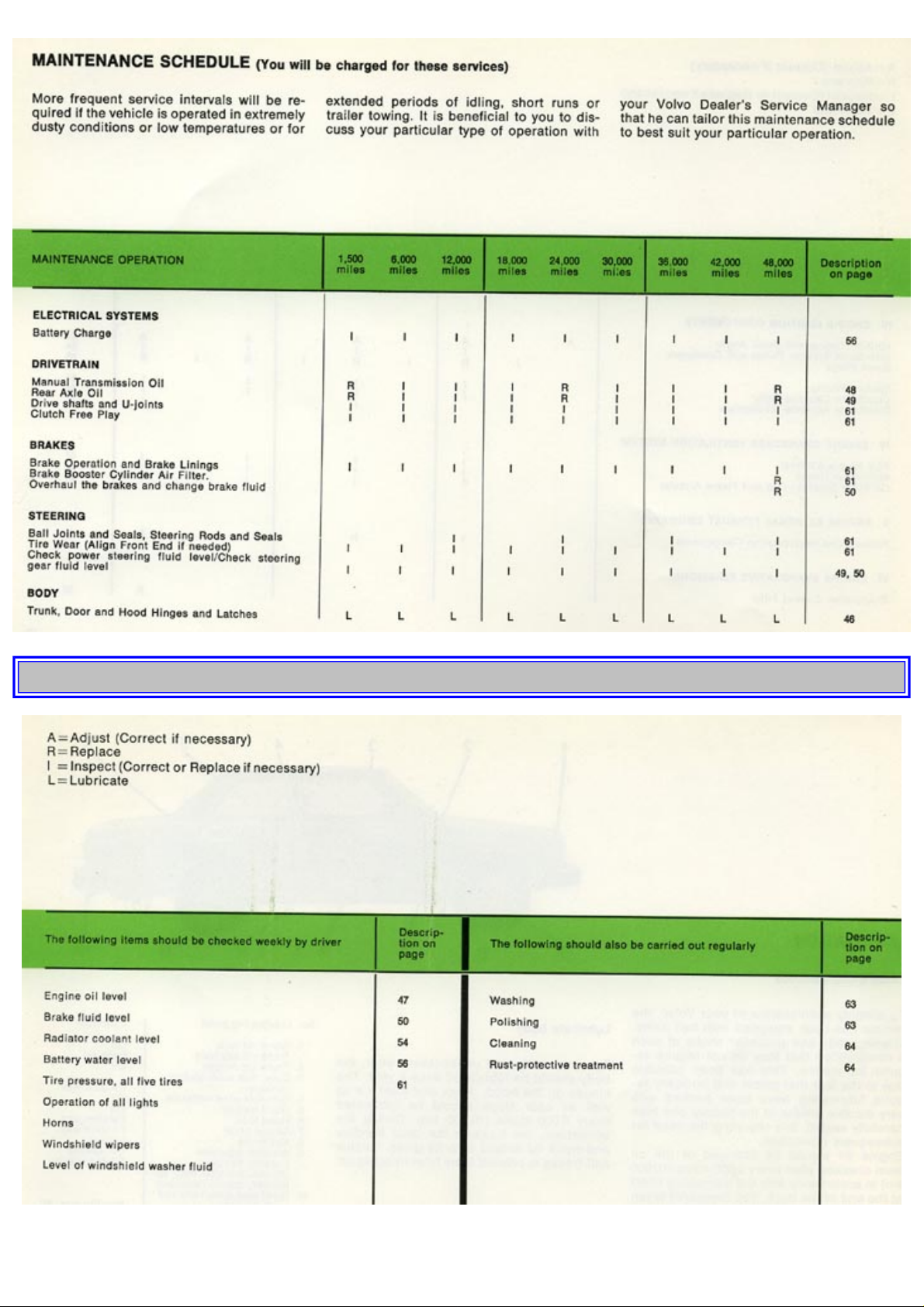
sake of convenience, the servicing procedures have been summarized in a maintenance schedule on the next four pages.
pg. 42 SERVICING
http://new.volvocars.com/ownersdocs/1974/1974%20142%20144%20145/74142144145_03.htm (1 sur 24) [2013-03-14 11:44:16]
Page 47
1974 Volvo 142 144 145
pg. 43 SERVICING
http://new.volvocars.com/ownersdocs/1974/1974%20142%20144%20145/74142144145_03.htm (2 sur 24) [2013-03-14 11:44:16]
Page 48
1974 Volvo 142 144 145
pg. 44 SERVICING
http://new.volvocars.com/ownersdocs/1974/1974%20142%20144%20145/74142144145_03.htm (3 sur 24) [2013-03-14 11:44:16]
Page 49
1974 Volvo 142 144 145
pg. 45 SERVICING
http://new.volvocars.com/ownersdocs/1974/1974%20142%20144%20145/74142144145_03.htm (4 sur 24) [2013-03-14 11:44:16]
Page 50
1974 Volvo 142 144 145
pg. 46 SERVICING
LUBRICATION
Chassis maintenance
To simplify maintenance of your Volvo, the vehicle has been equipped with ball joints, steering rods and propeller shafts of
such a construction that they do not require regular lubrication. This has been possible due to the fact that points that normally
require lubricating have been packed with very durable grease at the factory and then carefully sealed, this obviating the need
for subsequent lubrication.
Engine oil should be changed or the oil level checked after every 6,000 miles (10,000 km) in accordance with the lubricating
chart at the end of the book. The measures taken in this inspection are also to be found in the lubricating chart.
Always use only first-class lubricant of a well-known brand. The right lubricants in the right quantity at the right time will
increase both the lifetime and the reliability of your car.
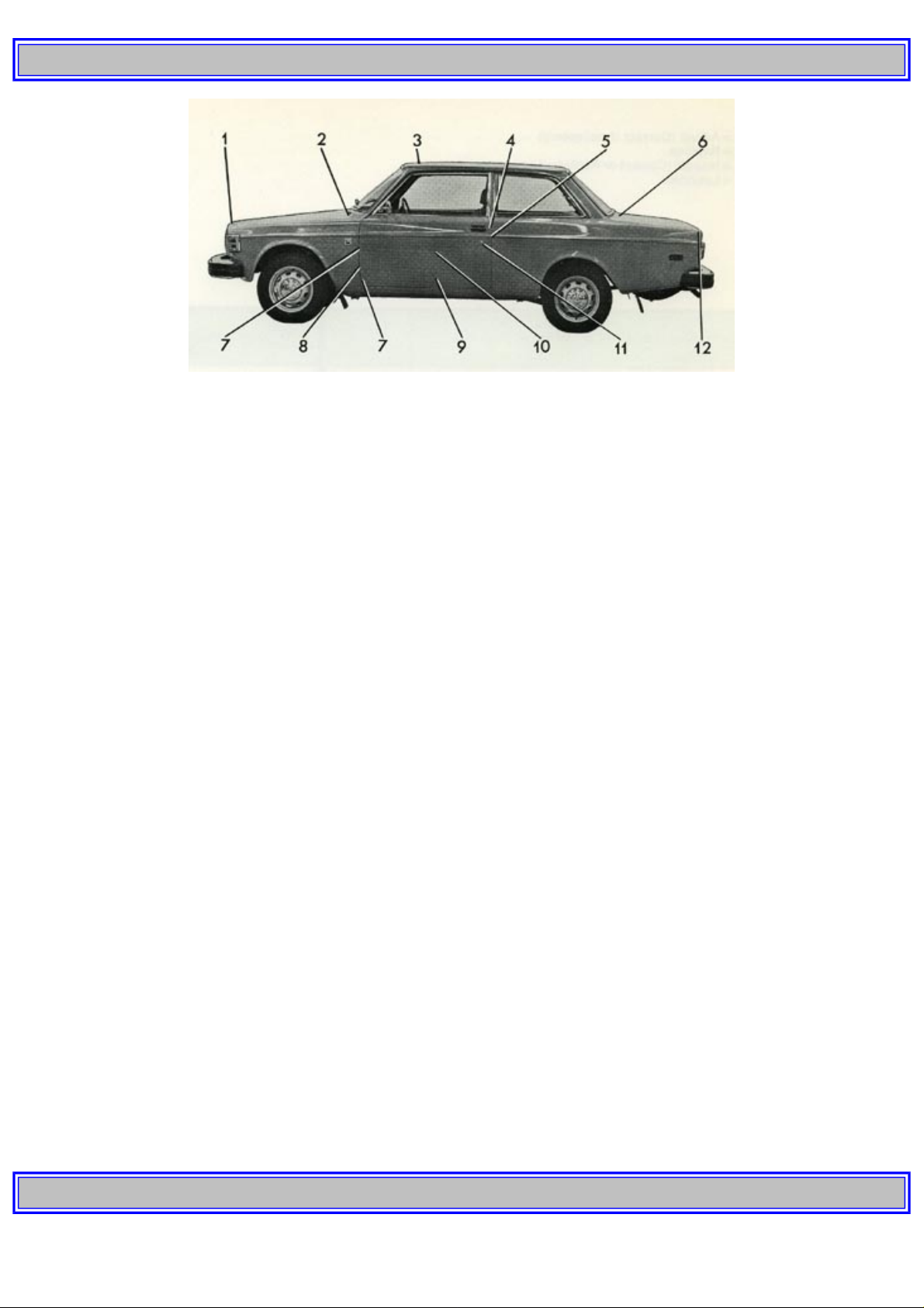
Lubricate body
To avoid rattle and unnecessary wear, the body should be lubricated once a year. The hinges on the hood, doors and trunk lid
as well as door stops should be lubricated every 6,000 miles (10,000 km). During the wintertime, the locks in the door handles
and trunk lid should also be given reliable anti-freeze to prevent them from freezing up.
No. Lubricating point Lubricant
1. Trunk lid lock
Trunk lid key hole
Oil
Lock oil
2. Trunk lid hinges Oil
3. Door lock outer sliding surfaces Paraffin wax
4. Sun-roof wind deflector Oil
5. Hood hinges Oil
6. Hood lock Paraffin wax
7. Striker plate Paraffin wax
8. Key holes Lock oil
9. Window regulator
Locking device
(Accessible after door upholstery panels removed)
Oil, grease
Silicon grease
10. Front seat slide rails and latch devices Paraffin wax, oil
11. Door hinges Grease
12. Door stop Paraffin, wax
pg. 47 SERVICING
http://new.volvocars.com/ownersdocs/1974/1974%20142%20144%20145/74142144145_03.htm (5 sur 24) [2013-03-14 11:44:16]
Page 51
1974 Volvo 142 144 145
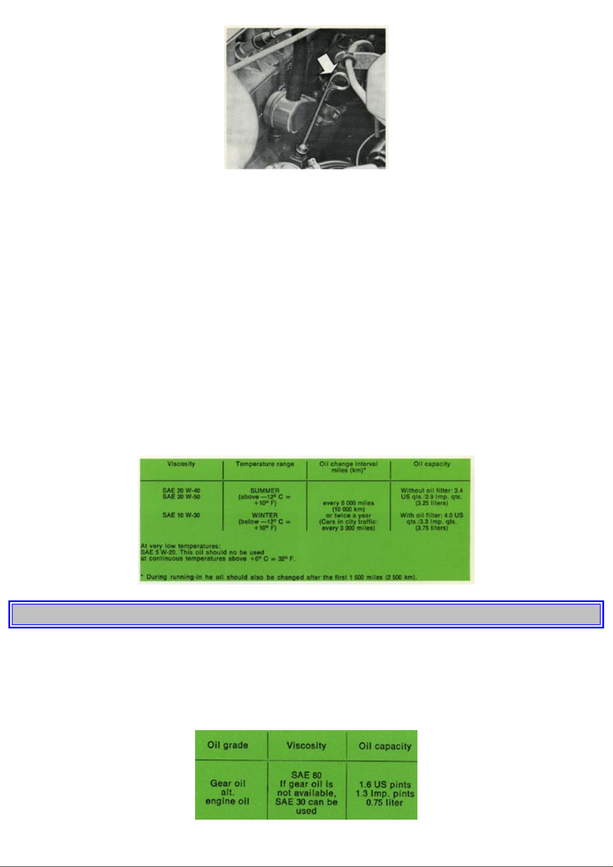
Check oil level in engine
The oil level in the engine should be checked each time the fuel tank is filled. The check should be made with the engine
switched off but warm and, in order to obtain comparable values, about one minute after the engine has been stopped. Wipe
the dipstick before measuring. The oil level should be between the two marks on the dipstick. It must never be permitted to go
down below the lower mark, but on the other hand, it should not be above the upper mark since oil consumption will then be
abnormally high. If necessary, top up by filling through the oil filler hole in the valve cover with new oil of the same type
already in the engine.
The distance between the marks on the dipstick corresponds to approx. 1 liter (1 qt) oil.
Change engine oil and filter
With a new or reconditioned engine, the oil should be changed after the first 1,500 miles (2,500 km). Subsequent oil changing
is according to the intervals given below. For engine lubrication, oil grade "For API Service SE" (API Service MS) is to be
used. Change the oil in the engine every 6,000 miles (10,000 km). For cars used in city traffic, the oil should however be
changed every 3,000 miles (5,000 km). Irrespective of the distance, the oil must be changed at least twice a year. For added
protection, the oil filter should be replaced at each oil change.
At very low temperatures (below -18° C = -0° F multigrade oil SAE 5 W-20 is recommended. However, this oil should not be
used when the temperature is continuously above 0° C (32° F).
The old oil is drained by removing the drain plug on the sump. Drain after driving when the oil is still warm.
pg. 48 SERVICING
Transmission without overdrive (M 40)
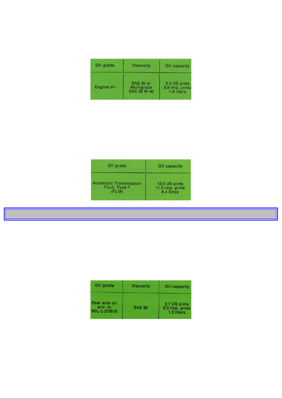
The oil in the transmission should be checked after every 6,000 miles (10,000 km). The oil level should be up to the filler hole.
If necessary top up with recommended oil. After every 24,000 miles (40,000 km) the oil in the transmission should be
changed. In a new or reconditioned transmission the oil should also be changed after the first 1,500 miles (2,500 km). The old
oil should be drained off immediately after the vehicle has been run while the oil is still warm.
http://new.volvocars.com/ownersdocs/1974/1974%20142%20144%20145/74142144145_03.htm (6 sur 24) [2013-03-14 11:44:16]
Page 52
1974 Volvo 142 144 145
Transmission with overdrive (M 41)
For cars equipped with an overdrive, the oil level should be checked and the oil changed parallel with similar procedure for the
transmission. The overdrive and the transmission have a common oil level and oil filler hole. Make sure when topping-up that
the oil runs over into the overdrive. The oil is drained out by removing the transmission drain plug and the cap for the
overdrive oil strainer.
At each oil change the oil filler of the overdrive should be cleaned. This should be done by a Volvo workshop.
Automatic transmission BW 35
The oil level should be checked every 6,000 miles (10,000 km). The filler pipe with graduated dipstick is under the hood just
in front of the firewall.
NOTE. The dipstick has different graduation marks for a warm and cold transmission. When the oil level is being checked,
the car should be standing level. With the engine idling in position "P", the level should be between the upper and lower
graduation marks on the dipstick. When topping-up is necessary, use only Automatic Transmission Fluid, Type F (FLM).
The oil in the automatic transmission should be changed every 24,000 miles (40,000 km).
pg. 49 SERVICING
Rear axle
The oil level in the rear axle should be checked after every 6,000 miles (10,000 km). The oil level should be up to the filler
hole. If necessary top up with the recommended oil. The oil in the rear axle should be changed after the first 1,500 miles
(2,500 km). The old oil is drained be removing the bottom plug. After this the oil should be changed every 24,000 miles
(40,000 km).
The oil should then be warm and the magnetic plug must be well cleaned. It is of great importance to the lifetime of the final
drive that particles and impurities from running-in are removed.
Limited slip differential
Cars equipped with a limited slip differential are delivered from the factory with a rear axle oil MIL-L-2105 B provided with
an additive for rear axles with differential. A similar type of oil should be used for subsequent topping-up and changing. Oil
level checking and oil changing are made at the same intervals and in the same way as for a rear axle without a limited slip
differential.
http://new.volvocars.com/ownersdocs/1974/1974%20142%20144%20145/74142144145_03.htm (7 sur 24) [2013-03-14 11:44:16]
Page 53
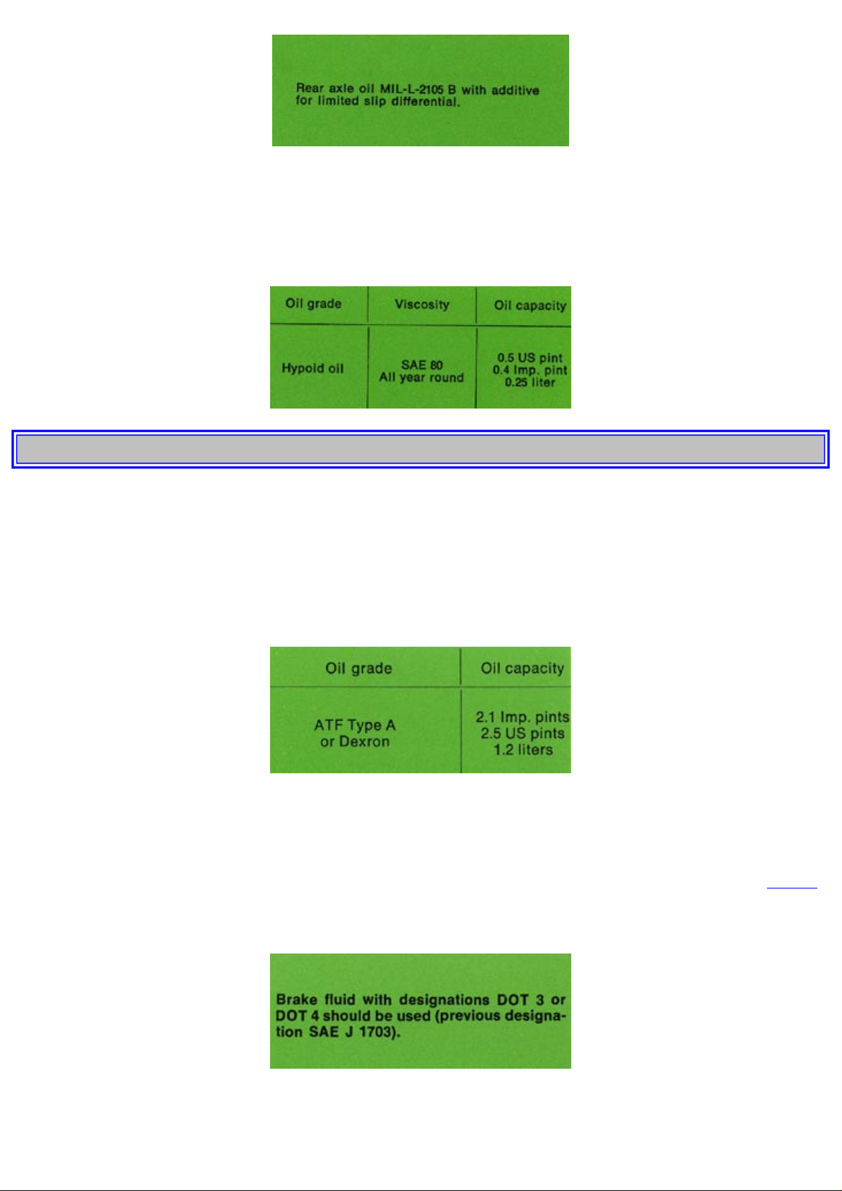
1974 Volvo 142 144 145
Manual steering
The oil level in the steering box should be checked after every 6,000 miles (10,000 km). The oil level should be up to the filler
plug. If necessary, top up with new oil. As a rule, the oil in the steering gear does not need to be changed except during
overhauling. Should the oil for any reason need to be changed, the old oil should be sucked up by an oil syringe which is
inserted down into the filler hole.
pg. 50 SERVICING
Power steering
The oil level in the power steering should be checked every 6,000 miles (10,000 km). Before checking wipe the oil container
clean. Then remove the cap and check the level with the engine not running. The oil level should be about 1/4" (5-10 mm)
above the level mark in the container. If the level is lower than this, top up with oil, with the engine stopped, to prevent air
from being sucked into the container. Start the engine and re-check the oil level, which should now fall to the level mark. Stop
the engine. The oil level, should now be about 1/4" (5-10 mm) above the mark.
The oil and filter in the power steering do not need replacing other than during repairs or reconditioning
Brake fluid
The brake system is provided with two brake fluid containers with a common filler hole. The brake fluid level should be
checked at regular intervals and should be between the "Max" and "Min" marks. Every 3rd year or 48,000 miles, the brake
system should be drained and the brake fluid replaced. Seals should also be replaced.
This service could conveniently be performed at the same time as the brake booster cylinder air filter is replaced, see
page 61.
At continuous hard driving, alp driving or similar where the brakes are used extensively, the brake fluid should be changed
annually. Extremely humid climates warrant the same recommendation.
ENGINE
Manifold and cylinder head bolts
http://new.volvocars.com/ownersdocs/1974/1974%20142%20144%20145/74142144145_03.htm (8 sur 24) [2013-03-14 11:44:16]
Page 54

1974 Volvo 142 144 145
The manifold bolts should be torqued at 1,500 mile inspection and then every 6,000 miles. Loose manifold could alter air/fuel
ratio and cause an increase in emission and/or poor driveability.
The cylinder head bolts should normally be torqued at 1,500 mile inspection and then not touched. However, loose cylinder
bolts will effect sealing properties and to some degree the valve tappet adjustment.
Drive belts
The belt tension can be checked by pressing in the fan belt at a point midway between the alternator and the fan. It should be
possible to press down the belt there about 3/8" (10 mm) with normal pressure (15-20.5 lb= 7-10 kp). This also applies to the
compressor drive belt (air conditioning).
The check can suitably be made in a Volvo workshop.
Also check the tension on the drive belt for the power pump. It should be possible to depress the belt about 3/8" (5 mm).
pg. 51 SERVICING
Crankcase ventilation
The engine is provided with positive crankcase ventilation which prevents the gases in the crankcase from being released into
the atmosphere. Instead they are sucked into the intake manifold and take part in the combustion process whereupon they are
blown out through the exhaust pipe together with the other combustion gases. Every 12,000 miles (20,000 km) remove and
clean the nipple (2) and the hoses (1 and 3). Rubber hoses and the flame protector (4) should also be replaced if they are in
poor condition.
Oil filter
The engine is equipped with a full-flow type oil filter, which means that all the oil passes through the filter on its way from the
oil pump to the various lubricating points. Impurities in the oil are collected in the filter and gradually block it. For this reason,
the filter must be changed at 1,500 miles and every 6,000 miles (10,000 km) thereafter.
If the oil filter is replaced without the engine oil being changed, the engine should be topped up with 1 pint (0.5 liter) of oil.
Fuel filter
The fuel filter is located on the firewall. This filter is to be changed after every 48,000 miles (80,000 km). The filter is replaced
as one complete unit.
http://new.volvocars.com/ownersdocs/1974/1974%20142%20144%20145/74142144145_03.htm (9 sur 24) [2013-03-14 11:44:16]
Page 55

1974 Volvo 142 144 145
Filter replacement should be made in a workshop.
pg. 52 SERVICING
Filter in fuel tank
A filter is installed in the suction line in the fuel tank. Its function is to prevent any dirt in the tank from being sucked up to the
fuel pump. The filter should be cleaned every 12,000 miles (20,000 km).
Fuel system cap, tank and lines, and connections
The effectiveness of the fuel system to contain hydrocarbons is largely dependent upon a leak free system. Check for proper
sealing of gasoline filler cap which contains "0" ring type seals. Check all evaporative hoses in vehicle for tightness and
freedom from leaks. Check fuel lines under vehicle and repair if necessary.
Air cleaner
Replace the air cleaner with a new one every 24,000 miles (40,000 km). The cleaner should be replaced more often if you are
driving regularly on dusty roads. No cleaning of any kind is to be made between the above mentioned intervals.
Filter replacement should be done in a workshop.
Evaporative control system
Vehicles intended for the U.S.A. market are equipped with a gas evaporative control system, which prevents gas fumes from
being released into the atmosphere. The system consists of an expansion container and a venting filter, which is filled with
active carbon.
When the engine starts, air is drawn through the venting filter and into the engine via the inlet duct. Gas fumes stored in the
active carbon are drawn by the air flow into the engine where they take part in the combustion.
Evaporative control filter
The carbon filter unit should be replaced after 48,000 miles (80,000 km). This work should be done in a workshop.
pg. 53 SERVICING
Valves
The valve clearance should be checked after every 12,000 miles (20,000 km). The check should be made in a workshop.
Compression test
To get some idea of the condition of the engine, a compression test should be carried out after every 12,000 miles (20,000
km). This test should preferably be made in a workshop.
Check throttle valve switch
The throttle valve switch should be checked every 12,000 miles (20,000 km) by a workshop.
Inspection of fuel injection electrical connections
The electrical connections and fuel lines in the injection system should be checked for chafing and corrosion every 12,000
http://new.volvocars.com/ownersdocs/1974/1974%20142%20144%20145/74142144145_03.htm (10 sur 24) [2013-03-14 11:44:16]
Page 56

1974 Volvo 142 144 145
miles (20,000 km) by a workshop.
Exhaust gas recirculation system (EGR)
Vehicles with a B20F engine in combination with automatic transmission are equipped with an exhaust gas recirculation
system. This makes for cleaner exhaust gases when driving on half throttle. The system consists of an EGR channel and an
EGR valve operated under a vacuum.
Clean Exhaust Gas Recirculation system
Every 12,000 miles the system should be cleaned, i.e. the metal pipe and rubber hose between valve and inlet manifold.
When cleaning at 12,000 miles the cold start valve should also be removed and wiped clean: Do not clean inside manifold
unless manifold is removed and it is considered necessary.
Check function of Exhaust Gas Recirculation valve
The function of the exhaust gas recirculation valve should be checked every 12,000 miles (20,000 km) by a workshop.
Clean and adjust spark plugs
Remove the spark plugs after every 6,000 miles (10,000 km) and adjust the electrode gap. The gap should be .028-.032" (.7-.8
mm).
Change spark plugs
The spark plugs should be changed every 12,000 miles (20,000 km).
Tightening should preferably be done with a torque wrench. When fitting new plugs, be sure to fit the right type (Bosch W 200
T 35 or corresponding).
When changing the plugs, check that the suppressor connectors are in good condition. Cracked or damaged connectors should
be replaced.
When changing spark plugs, clean the cables and cable terminals, also the rubber seals. If the car is driven on roads where salt
has been placed to counteract skidding, spray the cables with suitable water-resistant spray.
Ignition timing and dwell angle
Distributor breaker points and condenser
Distributor advance mechanism
The distributor braker points and condenser should be checked and the dwell angle
pg. 54 SERVICING
and ignition timing should be adjusted every 12,000 miles (20,000 km). All adjusting work should be done by a workshop
with the proper equipment. The distributor is one of the most sensitive units in the engine and careless handling can lead to
decreased engine output and high fuel consumption or even serious damage to the engine. The distributor advance mechanism
should be checked every 24,000 miles (40,000 km).
Ignition wiring
Ignition wiring system is composed of primary and secondary systems. The secondary systems are the high tension leads
connecting the distributor cap with the spark plugs and the coil.
These wires should be inspected at each engine tune-up, and should be replaced if cracked, frayed or damaged from abrasion.
It is important to clean all parts of this secondary system thoroughly because dirt greatly reduces the available voltage to the
spark plugs.
Distributor cap and rotor
Check the distributor cap and rotor for cracks, carbon formation, dirt and erosion.
Vacuum fittings, hoses and connections
Unstable idle, misfiring or poor emission control is often caused by leaking vacuum hoses or connections. Check hoses and
connections on distributor vacuum unit, EGR valve and port if so equipped, heater control servo systems and hydraulic brake
servo.
http://new.volvocars.com/ownersdocs/1974/1974%20142%20144%20145/74142144145_03.htm (11 sur 24) [2013-03-14 11:44:16]
Page 57
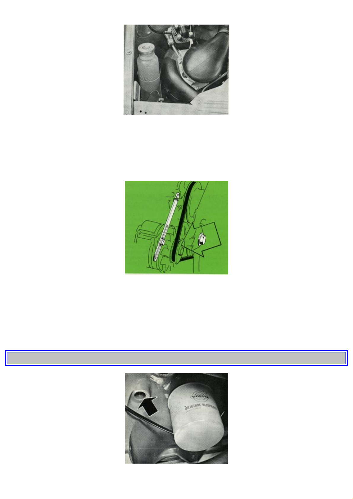
1974 Volvo 142 144 145
Check coolant level
The cooling system must be well filled with coolant and not leak if it is to operate at maximum efficiency. Check the coolant
level when filling up with fuel. The level should be between the "Max" and "Min" marks on the expansion tank. The check
should be made with particular thoroughness when the engine is new or the cooling system has been empty.
Do not remove the filler cap other than for topping-up with coolant. Frequent removal may prevent coolant circulation
between the engine and the expansion tank during engine warming up and cooling.
Top up with coolant
Top up with coolant by filling the expansion tank when its level has gone down to the "Min" mark. Use all the year round a
mixture of 50% reliable anti-freeze and 50% water. Top up to the "Max" mark.
NOTE: Do not top up with water only. Water by itself reduces both the rust-protective and anti-freeze qualities of the coolant.
It can also cause damage to the cooling system if ice should form in the expansion tank.
NOTE: In very warm parts of the country where there is little risk of frost, water can be used without anti-freeze. We
recommend, however, that rustproofing agent is added.
pg. 55 SERVICING
http://new.volvocars.com/ownersdocs/1974/1974%20142%20144%20145/74142144145_03.htm (12 sur 24) [2013-03-14 11:44:16]
Page 58
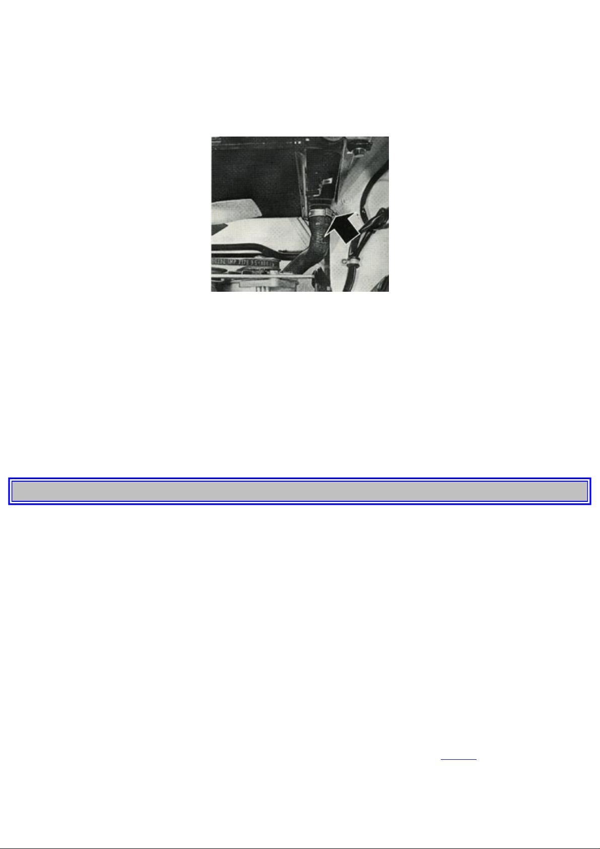
1974 Volvo 142 144 145
Change coolant
The coolant retains its properties for approx. 24,000 miles (40,000 km) when it should be changed. A suitable time to do this
would be in the autumn to preclude any damage by frost during the coming winter. To drain the cooling system, open the drain
tap located on the right-hand side of the engine and disconnect the hose connected to the bottom of the radiator. The expansion
tank is emptied by removing it from its brackets and lifting it to a sufficient height so that the coolant can flow into the
radiator.
Before filling with new coolant, flush the entire system with clean water.
The cooling system is filled with coolant through the filler opening on top of the radiator. When this is being done, the heater
control should be set to max. heat to ensure that the entire system is filled. Fill the radiator to the top and tighten the cap. Then
fill the expansion tank to the "Max" level or slightly above this. Run the engine for a short period, switch off the ignition and
allow the engine to cool. Check that the radiator is full and that the coolant in the expansion tank is at "Max". If necessary, top
up the system.
Cooling system, hoses and connections
Check all cooling system hoses and connections for defects or deterioration of hoses, clamps or fittings.
Checking and adjusting idling speed and mixture ratio
These checks should be made very 12,000 miles (20,000 km) by an authorized workshop.
pg. 56 SERVICING
Fuel
Regular grade of leaded or low-lead fuel (with an octane rating of at least 91 RON*) should be used.
* Research method.
Special instructions for work on the fuel injection system
Extreme cleanliness is essential when working on the injection system. Great care must be observed.
Injection system service should be handled by authorized Volvo dealers, using equipment intended for this service.
ELECTRICAL SYSTEM
Check the battery electrolyte level
Check the battery electrolyte level when fitting the tank with fuel. The level should be between 3/16-3/8" (5-10 mm) above the
top of the cell plates. If the level is too low, top up with distilled water.
Never check the electrolyte level by lighting a match. The gases formed in the cell are highly explosive.
Check the state of charge of the battery
The state of charge of the battery should be checked after every 6,000 miles (10,000 km). See
page 72 for battery data. At the
same time, check the lead terminals and terminal studs to make sure that they are tight, coated with grease and that the battery
is firmly in position.
http://new.volvocars.com/ownersdocs/1974/1974%20142%20144%20145/74142144145_03.htm (13 sur 24) [2013-03-14 11:44:16]
Page 59
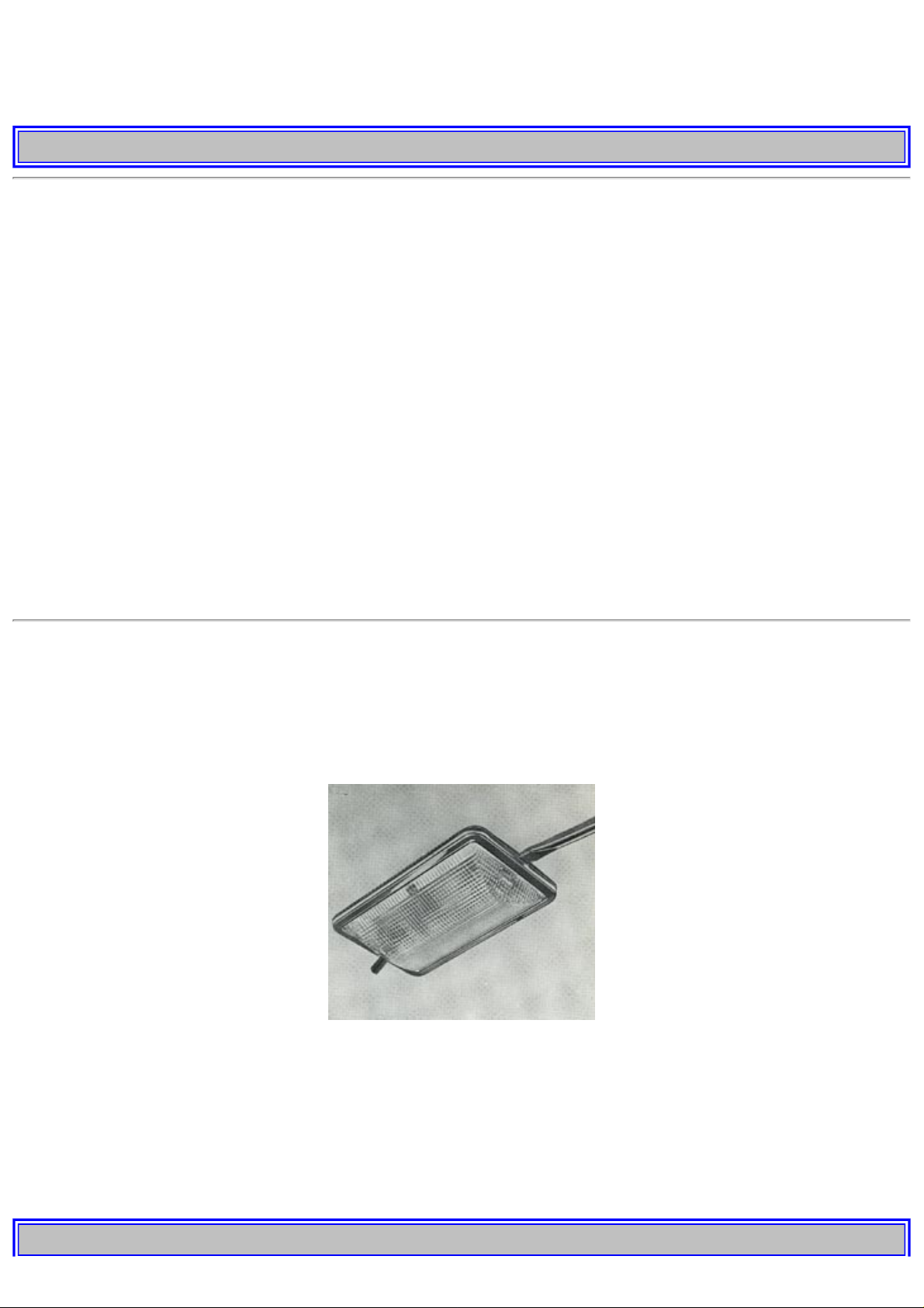
1974 Volvo 142 144 145
Check headlight alignment
The alignment of the headlights should be checked in a workshop periodically. Remember that the section of the road lit up by
the headlights can vary depending on the load in the vehicle.
pg. 57 SERVICING
This car is equipped with an alternator.
When changing the battery or when carrying out work involving the electrical system, the following should be observed.
1. A battery connection to the wrong terminal will damage the rectifiers. Before connections are made, check the polarity of
the battery with a voltmeter.
2. If assist batteries are used for starting, they must be properly connected to prevent the rectifiers from being damaged.
The ground lead from the assist battery for starting must be connected to the ground terminal stud of the car battery and the
positive lead from the assist battery for starting to the positive terminal stud.
3. If a fast charger is used for charging the battery, the car battery leads should be disconnected.
4. Never disconnect the battery circuit (for example, to change the battery) while the engine is running, as this will
immediately ruin the alternator. Always make sure that all the battery connections are properly tightened.
5. If any electrical welding work is made on the vehicle, the ground lead and all the connecting cables of the alternator must be
placed as near the welding point as possible.
Replace bulbs
The replacement of bulbs in the various lighting units is shown on the following pages. Make sure when installing lamps that
the guide pin on the socket fits into its corresponding recess.
When installing bulbs, do not touch the glass with your fingers. The reason for this is that grease, oil or any other impurities
can be carbonized onto the bulb and damage the reflector.
Replace bulb for roof light
To replace the bulb for the roof light, remove the light glass by pressing a narrow screwdriver straight into the hole in the glass
as shown in the picture. The glass can then be removed. The glass is replaced after the bulb has been changed by first hooking
it securely to the switch and then pressing it up with the hand.
Replace bulbs for instrument lighting and heater control lighting
Owing to the location of the bulbs, their replacement should be carried out by a Volvo workshop.
pg. 58 SERVICING
http://new.volvocars.com/ownersdocs/1974/1974%20142%20144%20145/74142144145_03.htm (14 sur 24) [2013-03-14 11:44:16]
Page 60
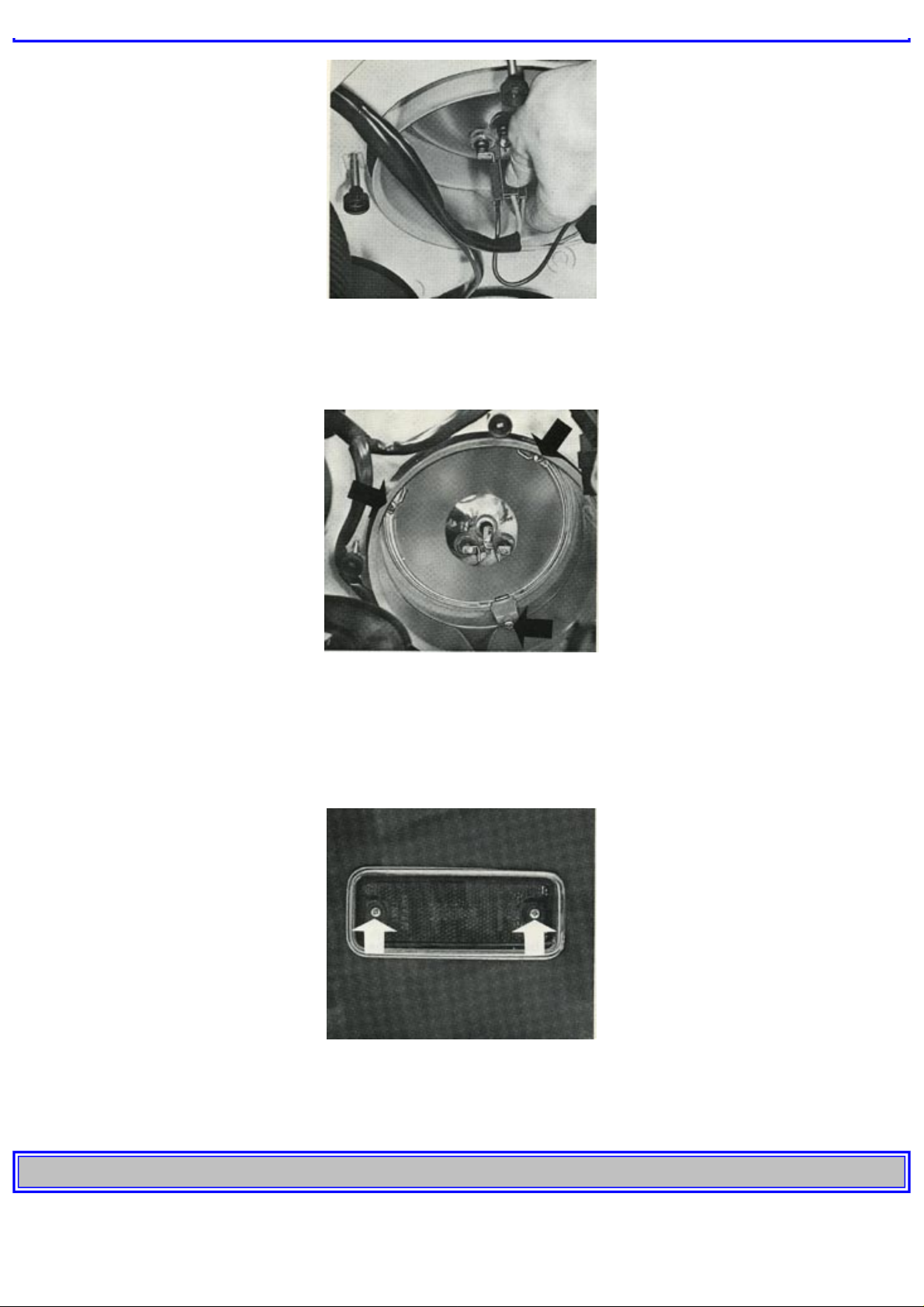
1974 Volvo 142 144 145
Change headlights (sealed Beam)
Sealed Beam headlights are changed as a complete unit.
1. Remove headlight contact by pulling it straight out backwards.
2. Slacken the three Phillips screws so much that the plastic holders can be removed.
3. Lift out the headlight backwards.
4. Install the new headlight and make sure that it is installed properly.
Check headlight alignment.
Replace bulbs for side marker lights
Remove the two Phillips screws which hold the glass. The bulb can now be removed by pressing it inwards and turning it
slightly anti-clockwise.
pg. 59 SERVICING
http://new.volvocars.com/ownersdocs/1974/1974%20142%20144%20145/74142144145_03.htm (15 sur 24) [2013-03-14 11:44:16]
Page 61
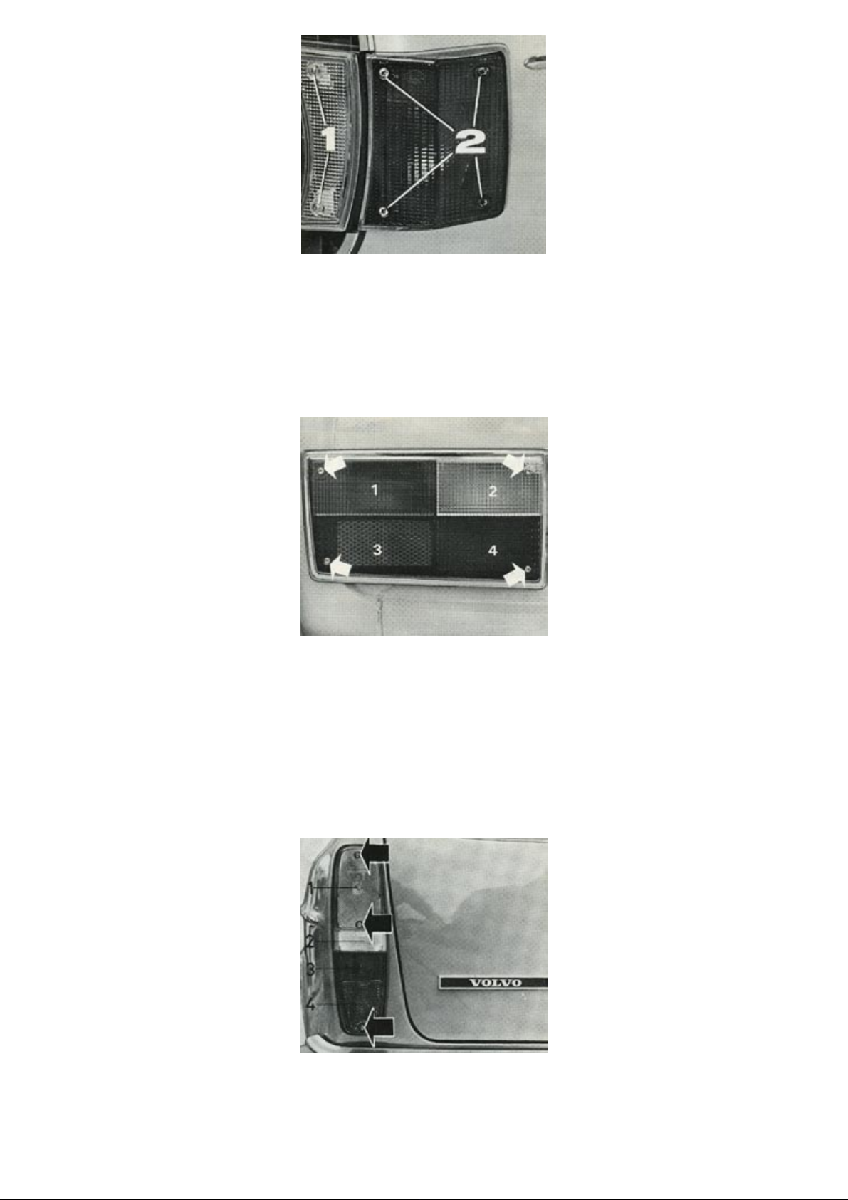
1974 Volvo 142 144 145
Replace bulbs for front parking lights
Remove the two Philiips screws (1) which hold the glass. The bulb is now accessible for changing.
Replace front flasher bulbs
Remove the four Philiips screws (2) which hold the glass. The bulb can now be removed by pressing it inwards and then turnit a little anti-clockwise.
Replacing the bulb for the rear turn signals, parking lights, stop lights and back-up lights
Remove the four Philiips screws which hold the glass. The bulbs can now be removed by pressing them inwards and turning
them slightly anti-clockwise at the same time.
1. Turn signal
2. Back-up light
3. Tail light
4. Stop light
Replace bulbs for rear turn signals, parking lights, stop lights and back-up lights 145 Station Wagon
Remove the three Philiips screws which hold the glass. The bulbs can now be removed by pressing them inwards and turning
them slightly anti-clockwise at the same time. Make sure that the sealing strip fits well against the glass when it is re-fitted.
From the top down the bulbs are:
http://new.volvocars.com/ownersdocs/1974/1974%20142%20144%20145/74142144145_03.htm (16 sur 24) [2013-03-14 11:44:16]
Page 62
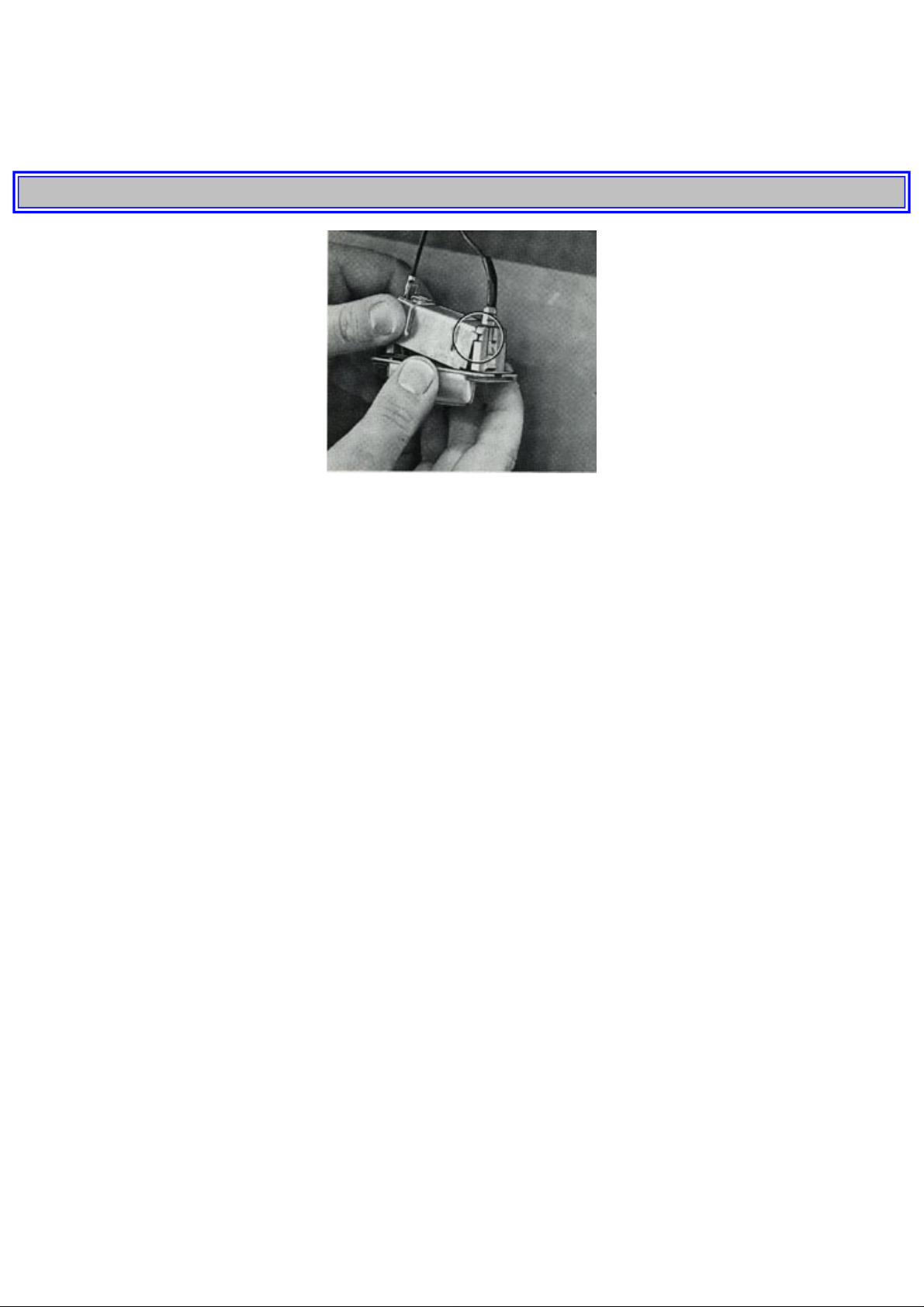
1974 Volvo 142 144 145
1. Flashers
2. Back-up light
3. Stop light
4. Tail light
pg. 60 SERVICING
Replace bulbs for license plate lighting
The license plate light is provided with two bulbs. Should any of them require replacing, proceed as follows:
1. Press in the tab catch in the bulb housing by inserting a screwdriver in the opening on the left-hand side of the housing. Pull
the bulb housing out of its attachment.
2. Pull out the casing end not provided with a guide pin.
3. The bulb is now accessible for replacing. When installing the unit, first insert the guide pins in the sockets and then press on
the casing. Check that the rubber strip fits properly in position and press the lamp housing securely into position.
Fuses
There are 12 fuses located at the bottom of the dashboard near the left front door. Reading downwards the fuses protect the
following:
1. Rear window wiper/washer
(145 only)
Cigarette lighter
8 A
2. Wiper/washer
Horn
Blower
16 A
3. El. heated rear window
Overdrive
16 A
4. Heater element, driver's seat
Back-up light
Seat belt pilot light
8 A
5. Turn signals
Instruments
Warning lights
5 A
6. Hazard warning
Starter cut-out relay
8 A
http://new.volvocars.com/ownersdocs/1974/1974%20142%20144%20145/74142144145_03.htm (17 sur 24) [2013-03-14 11:44:16]
Page 63
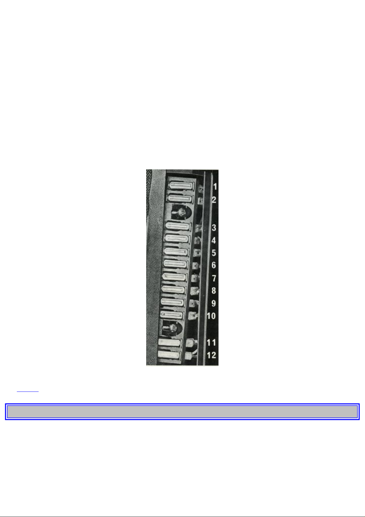
1974 Volvo 142 144 145
7. Fuel pump
Interior light, rear (145 only)
Clock
Glove box light
8 A
8. Stop light
Interior light
5 A
9. Ignition interlock
Buzzer, seat belt
5 A
10. Instrument lighting 5 A
11. Tail light, left
Side marker light, rear and front (left)
License plate light, left
(145, both lamps)
5 A
12. Tail light, right
Side marker light, front (right)
License plate light, right
5 A
Note: Fuse No. 9 controls the Seat Belt/Ignition Interlock System if the vehicle is so equipped.
See
page 25 for instructions on removing fuse No. 9 to facilitate emergency starting.
pg. 61 SERVICING
POWER TRANSMISSION
Check clutch free play
To avoid risk of the clutch slipping, the clutch travel should be checked and adjusted if necessary every 6,000 miles (10,000
km).
Check propeller shaft
After every 6,000 miles (10,000 km) or once a year the rubber seal on the spline shaft and the universal joints should be
checked. If the rubber seal is damaged, it should be replaced and the new seal filled with molybdenum disulphide grease.
http://new.volvocars.com/ownersdocs/1974/1974%20142%20144%20145/74142144145_03.htm (18 sur 24) [2013-03-14 11:44:16]
Page 64

1974 Volvo 142 144 145
BRAKES
Check brakes
After every 6,000 miles (10,000 km) the vehicle should be taken to a Volvo workshop for a check on the function of the
service and parking brake.
Replace booster cylinder air filter and overhaul brakes
Every third year or 48,000 miles (80,000 km) the car should be taken to a Volvo workshop for replacement of the booster
cylinder air filter.
See also
page 50 "Brake fluid".
FRONT END
Check ball joints, steering rods, etc.
After every 12,000 miles (20,000 km) the vehicle should be taken to a workshop for a check on the front end concerning
excessive play in the ball joints, steering gear, etc.
WHEELS AND TIRES
General
The car is equipped with pressed steel wheels. The wheel cap is bolted to the hub cap.
If possible, the wheels should always be used on the same side throughout their lifetime. This is particularly important for
studded winter tires, otherwise it can happen that the studs loosen.
Studded snow tires should also have a running-in period of between 300-600 miles (500-1,000 km). During this period try to
avoid driving hard round bends and at high speeds, also hefty braking and acceleration. Recommended for use in winter are
radial type tires with or without studs.
Tire chains can be used on all the car's four wheels providing that the chains are fine-linked and do not project so much from
the tire that they can chafe against the brake caliper or other components.
Strap-on emergency chains must not be used since the space between the brake calipers and wheel rims does not permit this.
Check tire wear pattern
Check the tires at regular intervals for damage and abnormal wear, also for particles which can fasten in the tread. Have them
balanced if necessary. Poorly balanced wheels will rapidly increase the wear on tires as well as make for poor travelling
comfort.
The tires have a so-called "wear indicator" in the form of a number of narrow strips running across or parallel to the tread.
When about 1/16" (1.5 mm) is left on the tread, these strips show up and warn the car owner in good time that the tire is
showing signs of wear.
Check tire pressure
Make a habit of checking the pressure in the tires regularly. The simplest way to do this is to check the pressure at a service
station while filling up with fuel. See
page 73 for the correct tire pressure. Do not forget the spare wheel when checking the
pressure.
During driving, the temperature of the tires rises and also the tire pressure in relation to the speed of the vehicle and its load.
Normally the pressure should only be checked when the tires are cold. When the tires are warm, a change in pressure
should take place only when air must be pumped into the tires.
Excessively low tire pressure is one of the most common reasons for tire wear. Tires which are insufficiently inflated also
result in difficult steering and high fuel consumption. Too high air pressure tends to make travelling less comfortable.
pg. 62 SERVICING
Changing a wheel
The spare wheel, jack and tool kit are stowed in the cargo compartment. When the car is to be jacked up, the jack should be on
level, firm ground. Avoid creeping under the car when it is jacked up since there is risk that the car might topple off the
jack, especially if the ground is soft. Before the vehicle is jacked up, the parking brake should be applied and one of the
gears engaged.
Also block one of the wheels standing on the ground.
http://new.volvocars.com/ownersdocs/1974/1974%20142%20144%20145/74142144145_03.htm (19 sur 24) [2013-03-14 11:44:16]
Page 65
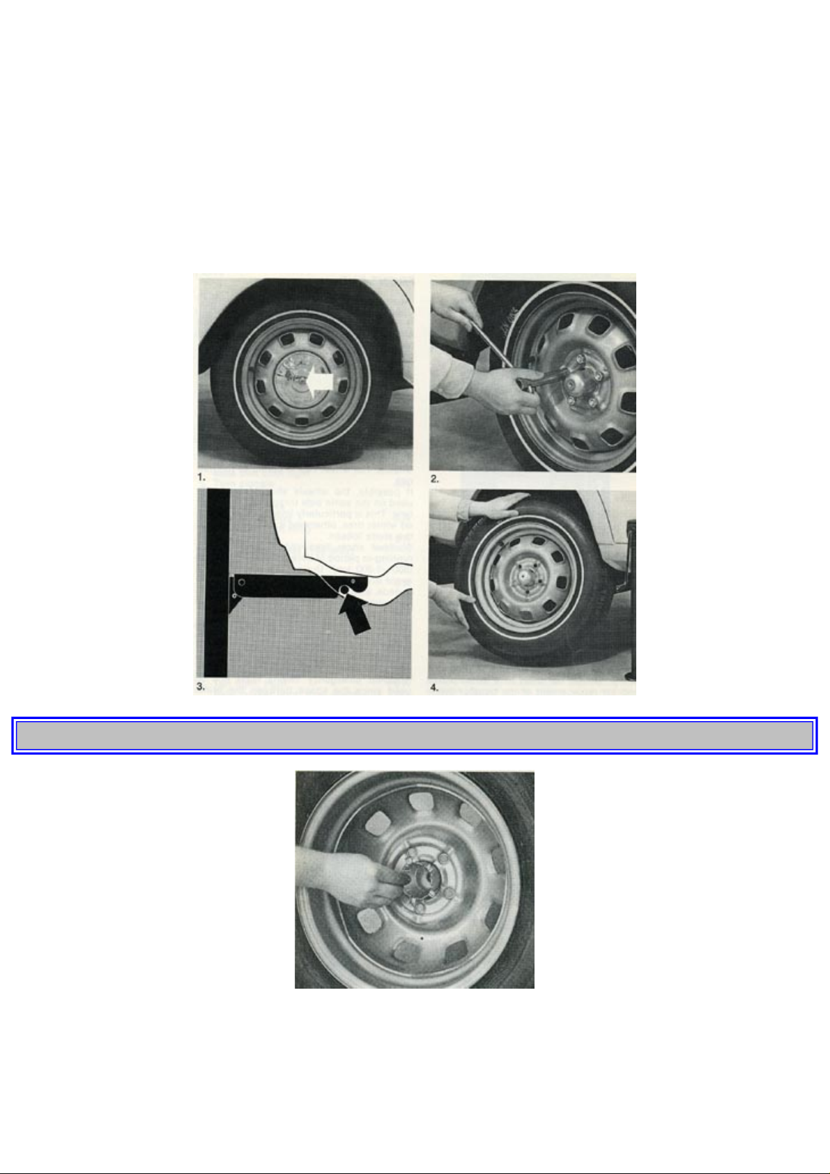
1974 Volvo 142 144 145
Removing
1. Unscrew the wheel cap.
2. Loosen the wheel nuts 1/2-1 turn with the help of the box spanner. All the nuts have right-hand threads which are loosened
by turning them anti-clockwise.
3. Insert the lifting arm of the jack in the appropriate jack attachment of the wheel to be changed. Make sure that the arm goes
in all the way. Jack upp the side of the car far enough to lift the wheel off the ground.
4. Unscrew the wheel nuts completely and lift off the wheel. Be careful when lifting off the wheel that the threads of the studs
are not damaged.
pg. 63 SERVICING
Installation
1. Install the hub cap on the wheel rim from the inside of the rim as shown in the picture above and clean the contact surfaces
between wheel and hub.
2. Lift on the wheel.
Tighten the nuts until the wheel makes good contact with the flange.
http://new.volvocars.com/ownersdocs/1974/1974%20142%20144%20145/74142144145_03.htm (20 sur 24) [2013-03-14 11:44:16]
Page 66

1974 Volvo 142 144 145
3. Lower the vehicle and tighten the nuts alternately.
4. Fit the wheel cap.
Do not rotate the raised wheel if the car is fitted with a limited slip differential as this will also move the other rear
wheel on the ground, so that the car may topple off the jack.
BODY
Washing
The car should be washed often since such things as dirt, dust, insects, tar spots etc adhere firmly to the body and may damage
the paintwork. During the winter, special care should be observed to wash off all road salt residue as soon as possible in order
to prevent corrosion.
When washing the car, do not expose it to direct sunlight. Soften up the dirt on the underside with a water jet and then rinse
the whole body with a light jet until the dirt has lessened. After this, wash off the dirt with a sponge, using plenty of water. Use
preferably lukewarm but not hot water.
A detergent can be used to facilitate washing. Special detergents are now available on the market - even household detergent
can be used.
A suitable mixture is about 1 1/2-3 1/2 fl. ozs. 5-10 cl) of fluid dish washer to 2.6 US galls=2.2 Imp. galls (10 liters) of water.
Asphalt spots and tar pittings can easily be removed with kerosene or Tar Removers but this should be done after the washing.
When a detergent is used, the car should be well rinsed down with clean water afterwards. Then dry carefully with a soft clean
chamois leather. Use different leathers for the windows and the remainder of the car otherwise using the same leather can
cause greasy smears on the windows. When washing the car, remember to clean the draining holes in the doors and bottom
rails.
Chromed parts
Chromium-plated and anodized parts should be washed with clean water as soon as they become dirty. This is particularly
important if you drive on gravel roads which are treated with chemicals to keep the dust down or in the winter when salt is
used to melt the snow. After the car has been washed, apply wax or anti-rust preparation.
Polishing (waxing)
The vehicle does not need polishing until the surface finish begins to lose its lustre and normal washing is no longer sufficient
to make it shine again and remove the layer of dirt on the surface. Under normal conditions it is sufficient to polish the vehicle
a couple of times a year on condition that it is carefully looked after and thoroughly washed as soon as it has become dirty or
dusty. Before the vehicle is polished, it should be carefully washed and dried to avoid scratches on the paintwork.
Before applying wax, make sure that the surface is absolutely clean. It may often be necessary to use kerosene for cleaning.
Waxing should neither be considered as a substitute for polishing nor as a necessary protection for the paintwork against
unfavourable weather. For the most part waxing is not necessary until one year after delivery of the car.
pg. 64 SERVICING
Cleaning the upholstery
The upholstery in your Volvo is a combination of fabric and plastic.
Generally the fabric in the upholstery can be cleaned with soapy water or a detergent. For more difficult spots caused by oil,
ice cream, shoe polish, grease, etc. carbon tetrachloride-gasoline (equal parts carbon tetrachloride and chemically pure
gasoline) can be used.
The plastic in the upholstery can be washed with a mild detergent or in more difficult cases with some household detergent.
On no account must gasoline, naptha, carbon tetrachloride or similar cleaning agent be used on the plastic in the
upholstery, since these can damage the plastic.
Cleaning floor mats
The floor mats should be hoovered or brushed clean regularly, especially during the winter when they should be taken out for
drying. Take the opportunity of cleaning thoroughly at the same time where the mats have lain.
Spots on textile mats can be removed with a mild detergent.
http://new.volvocars.com/ownersdocs/1974/1974%20142%20144%20145/74142144145_03.htm (21 sur 24) [2013-03-14 11:44:16]
Page 67
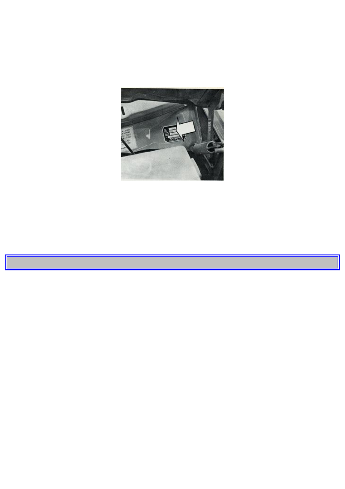
1974 Volvo 142 144 145
Rubber mats can be washed with methylated spirit which must be subsequently washed off with water.
Anti-rust treatment
Your Volvo is anti-rust treated at the factory. Inspection and any touching-up of the anti-rust protection should be done at
regular intervals and at least once a year. The enclosed body sections should also be anti-rust treated by means of spray
application at least once a year.
If any touching-up of the anti-rust protection is necessary, this should be done immediately to prevent moisture from seeping
in and consequently damaging it.
Paint touch-up
Paint damage requires immediate attention to avoid rusting. Make it a habit to check the finish regularly and touch-up if
necessary, for instance when washing the car.
Paint repairs require special equipment and skill and you should contact your Volvo dealer for any extensive damages.
However, minor scratches are a "nuisance job" for a paint shop and you can save a lot by repairing yourself. Volvo dealers can
supply touch-up paint in tins or spray cans.
NOTE: Use the paint code which you will find on the Vehicle Designation Plate on the bulkhead.
pg. 65 SERVICING
Scars on the surface where the paint has not been completely penetrated, can be made directly after light scraping to remove
dirt.
Deeper scars, down to the bare metal:
1. Scrape or sand the damaged surface lightly and break the edges of the scar.
2. Thoroughly mix the primer and apply it with a small brush or a match.
3. When the primed surface is dry, the paint can be applied by a brush. Mix the paint thoroughly, apply several thin paint coats
and let flush after each application.
4. If there is a longer scratch, you may want to mask to protect surrounding paint.
NOTE: The vehicle should be well cleaned, dry and have a temperature exceeding 60°F.
BEFORE A LONG-DISTANCE TRIP
If you are thinking of traveling abroad with your car or taking a long journey, you should have the car checked at a Volvo
workshop. You will enjoy your journey better if you know that your car is in perfect trim. Irritating incidents can be avoided
as well as expensive and time-absorbing stoppages. Wherever you go there should be a Volvo workshop within easy call to
attend to your car if required.
However, it is always a good idea before making a trip to ensure that, at least on a minor scale, you have with you a
comprehensive touring kit. This is particularly the case if you anticipate widely varying conditions as regards climate, roads
and the prevalence of much dust. Many workshops stock special kits for this purpose. Remember when filling up with fuel to
observe the existing fuel recommendations. If you prefer to look over your vehicle yourself, the following tips are worthwhile
noting:
1 Check brakes, front wheel alignment and steering gear.
http://new.volvocars.com/ownersdocs/1974/1974%20142%20144%20145/74142144145_03.htm (22 sur 24) [2013-03-14 11:44:16]
Page 68

1974 Volvo 142 144 145
2 Check engine and drive units with regard to fuel, oil, coolant leakage.
3 Examine tires carefully. Replace worn tires.
4 Check engine is running satisfactorily and that fuel consumption is normal.
5 Examine state of charge of the battery and clean terminals.
6 Check tool equipment.
7 Check lighting.
COLD WEATHER
When cold weather is on the way, it is time to think of the winter servicing of your car. The first night of frost can come as a
unpleasant surprise unless preventive precautions have been taken.
Engine cooling system
A good quality anti-freeze/summer coolant should be used all the year round. Thus, the cooling system should always contain
water plus anti-freeze and rust inhibitor, even during the summer. Experience has also shown that extremely weak anti-freeze
solutions (10-25%) are very unfavourable from the point of view of rust protection. For this reason, the quantity of antifreeze/summer coolant should amount to about 50% of the coolant, that is, 4.5 US qts = 3.8 Imp. qts 4.3 litres), this lowering
the freezing point to -31° F(-35°C).
Radiator spirit is not recommended as an anti-freeze agent since at evaporates at normal engine temperature.
pg. 66 SERVICING
Engine fuel system
During the wintertime with large variation in temperature, condensate forms in the fuel tank and this can impair the running of
the engine. This can be eliminated by adding gas-line anti-freeze to the fuel. Also, there is less risk of condensation water
forming if the tank is kept well-filled.
Engine lubricating system
During the winter multigrade oil 10W-30 should be used for the engine lubricating system. At very low temperatures (below 4°F=-20°C) multigrade oil SAE 5 W-20 is recommended. These oils reach the lubricating points in the engine more easily at
low temperature and also facilitate cold starting. See
page 47.
Electrical system
The electrical system in the vehicle is subjected to greater stresses during the winter than during the warm summer months.
The lighting and starter motor are used more and since the capacity of the battery is also considerably lower at low air
temperature, the state of charge must be checked more often and, if necessary, the battery charged. If the battery voltage is
excessively low, there is risk of the battery being damaged by frost.
Brake system
During very cold weather the brakes are subjected to splash and condensate which can result in the parking brake freezing up
if left on.
When you park the car, do not apply the parking brake but engage first gear or reverse and if possible place blocks behind the
wheels. See also
page 30.
Windshield washers
Just as anti-freeze is added to the cooling system during the winter to prevent frost damage, anti-freeze should also be added to
the water container for the windshield washer. This is particularly important because the windshield during the winter
frequently becomes dirty and is often splashed with water which rapidly freezes and thus necessitates the frequent use of the
windshield washer and wipers. Your Volvo dealer can supply you with suitable anti-freeze for this purpose.
Anti-freeze for door locks
A frozen door lock is one of the most irritating things that can happen to a car owner. Many valuable minutes early in the
morning can be wasted warming up keys and melting ice in locks. Remember this in good time and lubricate the locks in
advance with some suitable anti-freeze agent. Such agents are now available in small handy tubes which can easily find room
in a handbag or coat pocket.
http://new.volvocars.com/ownersdocs/1974/1974%20142%20144%20145/74142144145_03.htm (23 sur 24) [2013-03-14 11:44:16]
Page 69

1974 Volvo 142 144 145
Top of Page
http://new.volvocars.com/ownersdocs/1974/1974%20142%20144%20145/74142144145_03.htm (24 sur 24) [2013-03-14 11:44:16]
Page 70

1974 Volvo 142 144 145
1 9 7 4
VOLVO
142 144 145
pg. 67 SERVICE DIAGNOSIS
The information given below is only intended to serve as a guide in localizing and temporarily
correcting minor faults. After having carried out any such measures, have them checked and adjusted
by an experienced mechanic.
Note: An asterisk "*" following the item under the Corrective action in the chart indicates the point to
be serviced by an authorized Volvo dealer.
Condition: Starter fails to operate (or operates very slowly)
Possible cause
Seat belt not fastened.
If the vehicle is equipped with an Ignition
Interlock System, check to see if the front
seat belts have been fastened after the
occupants have been seated and before the
ignition key is turned to the starting
position. See
page 25 for instruction on
emergency starting.
Weak battery or dead cell in battery.
With the ignition switch in the "Driving" or
"On" position, check to see if the warning
lights on the dashboard come on and if they
go out when the starter is engaged.
If the lights do not come on or if they go
out when the starter is engaged, the battery
is discharged, or see below.
Loose or corroded battery cable terminals.
Check battery terminals and clamps, clean
or replace if necessary. Check that the
starter cable is tightened.
A ground strap, which connects the body
and the rear end of the engine, should also
be checked for corrosion and looseness.
http://new.volvocars.com/ownersdocs/1974/1974%20142%20144%20145/74142144145_04.htm (1 sur 11) [2013-03-14 11:44:30]
Page 71
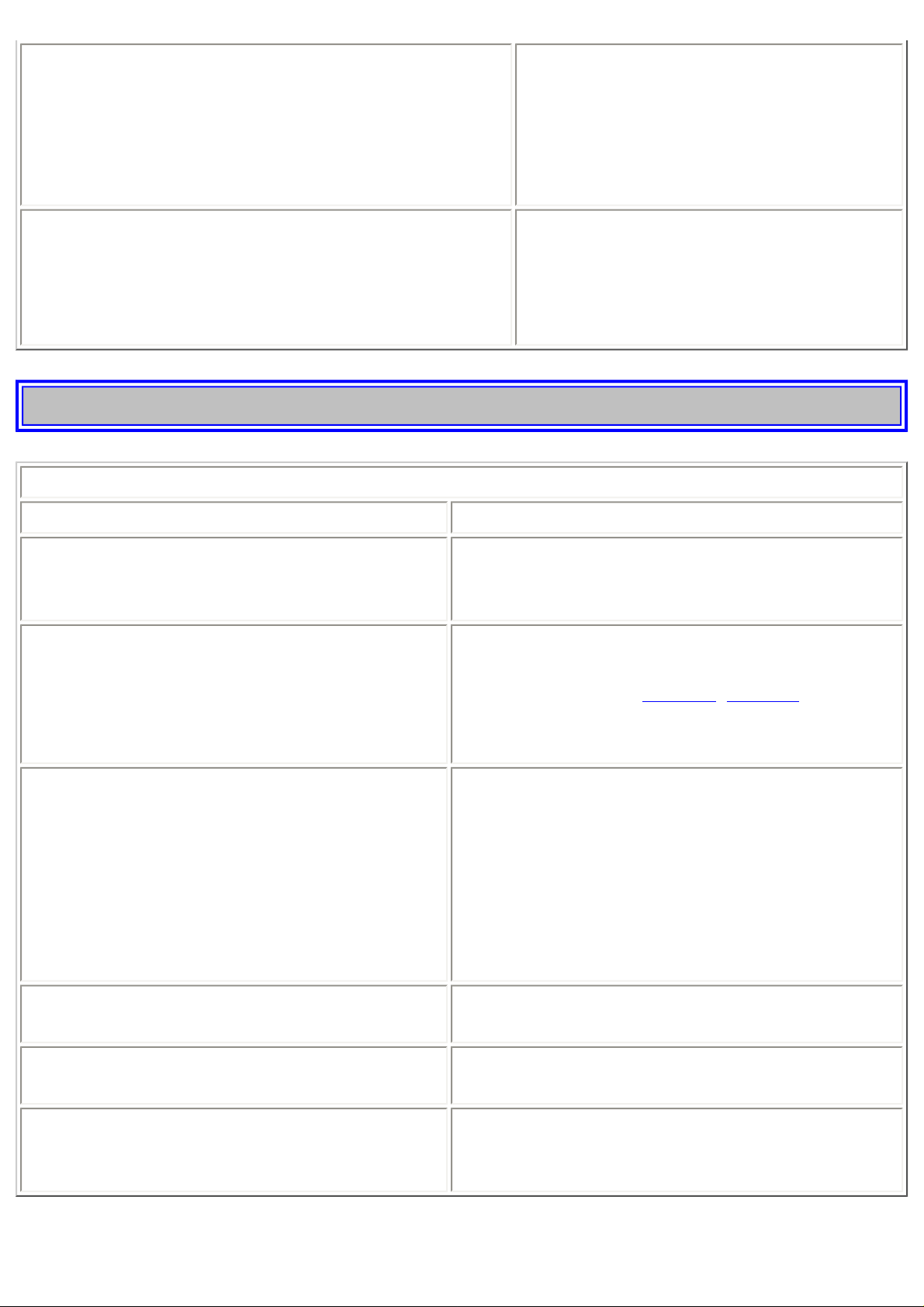
1974 Volvo 142 144 145
Open circuit between ignition/starter switch and
ignition terminal on starter.
The circuit is closed if a clicking sound is
heard from the starter when it is engaged.
If no clicking sound is heard, check that the
blue wire at the starter is tightened.
If still no clicking sound is heard, the
ignition lock or the wire are defective.
Starter motor defective.
If the above checks have been performed,
and no fault is evident, the starter may be
defective.
(Note: At this cause, the headlights do not
dim when starter is engaged.)
pg. 68 SERVICE DIAGNOSIS
Condition: Starter motor operates but engine does not start.
Possible cause Correction
Intake system leaking.
Check that the rubber bellow, connecting air
cleaner and intake manifold, is tight and not
defective.
No fuel reaching engine.
Check for fuel in the tank.
Check fuse No. 7.
Check the two relays,
page 31, p. 23-24
A clicking sound should be heard from the starter
if these relays are functioning.
No spark.
Remove the high tension leads at one of the spark
plugs and screw out the radio interference
suppressor. Hold the lead approx. 3/8" from the
valve cover and run the starter.
If there is no spark, check:
that the high tension lead from the coil to the
distributor cap is connected
that the wires to distributor and coil are connected.
Spark plugs, high tension leads or distributor
cap worn (defective).
Clean the parts with a dry cloth or spray a moisture
remover.
Gold start injector out of order.
Test the cold start injector function at cold and hot
engine.*
Rest pressure incorrect.
Test rest pressure and the fuel system for leaks. If
no fault is found, according to above, see a Volvo
Dealer.
http://new.volvocars.com/ownersdocs/1974/1974%20142%20144%20145/74142144145_04.htm (2 sur 11) [2013-03-14 11:44:30]
Page 72
1974 Volvo 142 144 145
pg. 69 SERVICE DIAGNOSIS
Condition: Erratic running (Misfiring)
Possible cause Correction
Intake system leaking.
Check that the rubber bellow, connecting air
cleaner and intake manifold, is tight and not
defective.
Exhaust Gas Recirculation Valve leaking. Test the valve function.*
Spark plugs, high tension leads or distributor cap
worn (Defective).
Clean cap and leads, check the cap for cracks.
Defective spark plugs. Remove, clean or replace spark plugs.
Cold start injector leaking.
Test the injector function.*
(This is a possible cause if the engine RPM is
"rolling").
Uneven compression. Test the compression of each cylinder.
Condition: Engine stalls at irregular intervals
Possible cause Correction
Defective wires.
Check wire terminals at: fuel pump, fuse No. 7, coil,
distributor, ignition switch, relays and air flow sensor.
Intake system leaking.
Check that the rubber bellow, connecting air cleaner and
intake manifold, is tight.
Too low idle. Adjust.*
Fuel filter clogged. Clean tank fuel filter and replace line fuel filter.
Exhaust Gas Recirculation Valve seizing.
Replace valve*
(Engine will die on idle.)
pg. 70 SERVICE DIAGNOSIS
Condition: Low top speed, loss of power
Possible cause Correction
Air filter clogged. Check air filter.*
Throttle misadjusted.
Check that the throttle touches the high speed stop when the
accelerator is fully depressed.*
Fuel filter clogged. Clean fuel tank filter and replace fuel line filter.*
http://new.volvocars.com/ownersdocs/1974/1974%20142%20144%20145/74142144145_04.htm (3 sur 11) [2013-03-14 11:44:30]
Page 73
1974 Volvo 142 144 145
Incorrect timing or dwell angle. Check and adjust.*
Condition: Excessive fuel consumption
Possible cause Correction
Fuel lines leaking. Check tightness.
Spark plugs worn. Replace plugs
Incorrect timing. Check/adjust.*
Air filter clogged. Check/replace.*
Control pressure incorrect. Check/replace control pressure regulator.*
Cold start injector leaking.
Replace injector.*
(A leaky cold start injector also causes uneven idle and difficult
starting.)
pg. 71 SERVICE DIAGNOSIS
Condition: Dieseling
Possible cause Correction
Injector leaking. Check air sensor plate and rest pressure.*
Condition: Misfiring at highway driving
Possible cause Correction
Spark plugs fouled.
Continue driving and wait for spark plugs to clean up themselves. Possibly
clean or replace spark plugs on a later occasion.
pg. 72 SPECIFICATIONS
Type designations
In all correspondence concerning your vehicle with the dealer and when ordering parts, the V.I.N.
number should always be quoted.
1. V.I.N. (Vehicle Identification Number)
V.I.N. plate located at the foot of the left door port. The V.I. N. is also stamped on right door pillar.
2. Safety Certification Label
Your Volvo has been built to comply to all North American safety and anti-pollution regulations and
evidence of this can be seen from the certification label on the firewall in the engine compartment. For
further information regarding these regulations, please talk to your selling dealer.
http://new.volvocars.com/ownersdocs/1974/1974%20142%20144%20145/74142144145_04.htm (4 sur 11) [2013-03-14 11:44:30]
Page 74
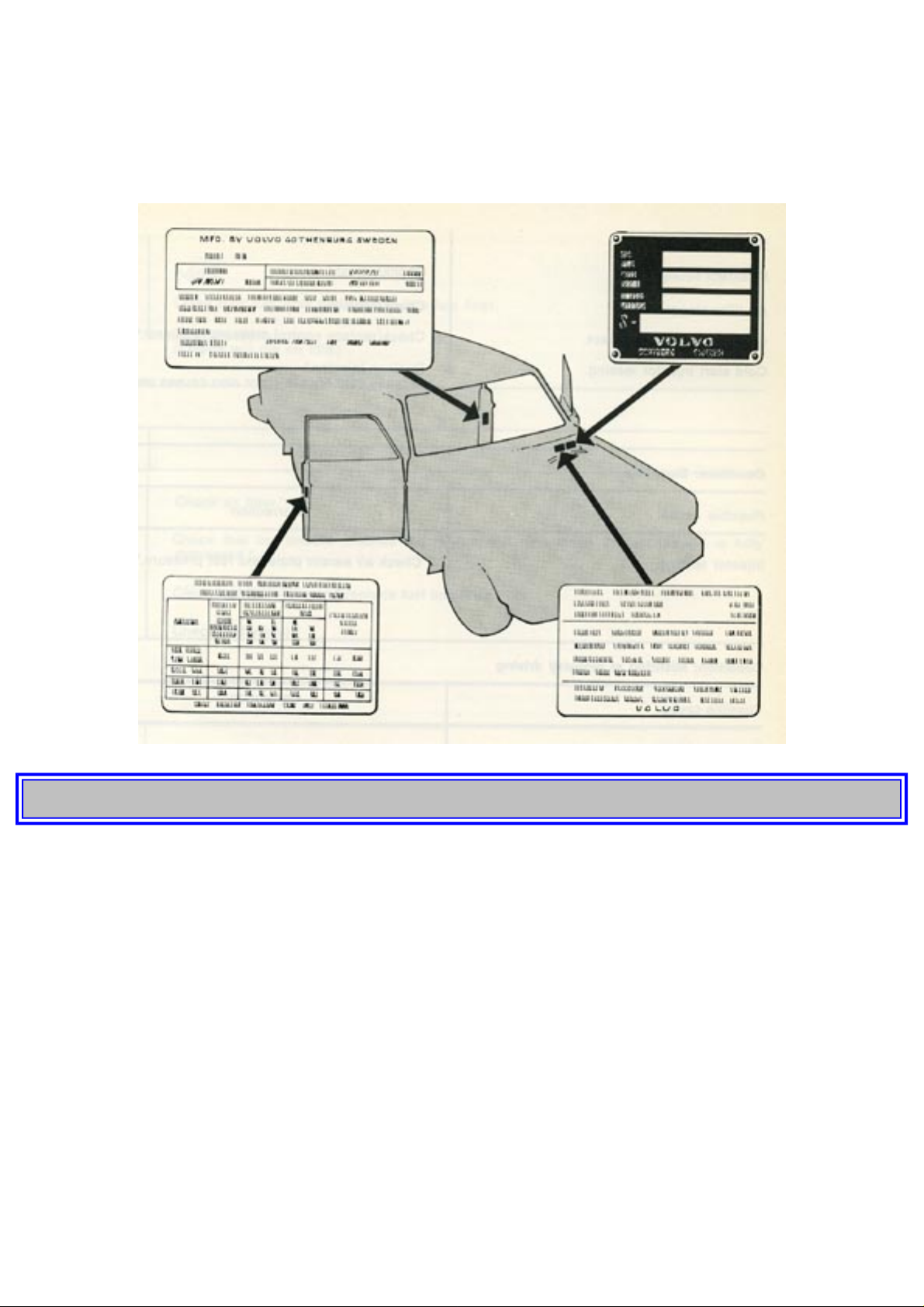
1974 Volvo 142 144 145
3. Model Plate
Vehicle type designation, code number for color and upholstery: on bulkhead.
4. Tire Information Plate
pg. 73 SPECIFICATIONS
DIMENSIONS AND WEIGHTS
142 144 145
Length 188.2" (478 cm) 188.2" (478 cm) 188.2" (478 cm)
Width 67.3" (171 cm) 67.3" (171 cm) 67.3" (171 cm)
Height, curb weight 57.5" (146 cm) 57.5" (146 cm) 57.8" (147 cm)
Wheelbase 103.1" (262 cm) 103.1" (262 cm) 103.1" (262 cm)
Ground clearance, full
load
4.9" (12.5 cm) 4.9" (12.5cm) 4.9" (12.5cm)
Track, front 53.1" (135 cm) 53.1" (135 cm) 53.1" (135 cm)
- rear 53.1" (135 cm) 53.1" (135 cm) 53.1" (135 cm)
http://new.volvocars.com/ownersdocs/1974/1974%20142%20144%20145/74142144145_04.htm (5 sur 11) [2013-03-14 11:44:30]
Page 75

1974 Volvo 142 144 145
Turning circle, between
curbs
31.5' (9.6 m) 31.5' (9.6 m) 31.5' (9.6 m)
- with power steering 32.5' (9.9 m) 32.5' (9.9 m) 32.5' (9.9 m)
Curb weight
2778-2833 lbs (12601285 kg) depending on
type
2833-2889 lbs (12851310 kg) depending on
type
2867-2977 lbs (13001350 kg) depending on
type
Gross vehicle weight
(GVW)
3957 lbs (1795 kg) 3957 lbs (1795 kg) 4185 lbs (1898 kg)
Permissible axle weight,
front
1786 lbs (810 kg) 1786 lbs (810 kg) 1786 lbs ( 810 kg)
- rear 2172 Ibs (985 kg) 2172 lbs (985 kg) 2602 lbs (1180 kg)
Permissible roof load 220 lbs (100 kg) 220 lbs (100 kg) 220 lbs (100 kg)
Max. trailer weight 2000 lbs (908 kg) 2000 lbs (908 kg) 2000 lbs (908 kg)
Max. hitch load 160-200 lbs (75-90 kg) 160-200 lbs (75-90 kg) 160-200 lbs (75-90 kg)
Cargo space 145
Length with rear seat up 44.5" (113 cm)
Length with rear seat down 74.0" (188 cm)
Maximum width 52.4" (133 cm)
Height 33.0" ( 84 cm)
Volume with rear seat up 53.0 cu.ft. (1.5 m3)
Volume with rear seat down 67.0 cu.ft. (1.9 m3)
Cargo opening, maximum width 45.7" (116 cm)
Cargo opening, maximum height 30.7" ( 78 cm)
pg. 74 SPECIFICATIONS
ENGINE
Type designation Volvo B 20 F
Output (SAE J 245) at rpm 112 hp/6000
Max. torque (SAE J 245) at rpm 115 lb ft (16 kpm)/3500
Number of cylinders 4
Bore 3.5" (88.9 mm)
Stroke 3.15" (80 mm)
Displacement 1.99 litres
Compression ratio 8.7:1
Valves Overhead
Valve clearance, warm and cold inlet and exhaust .016-.018" (.40-.45 mm)
http://new.volvocars.com/ownersdocs/1974/1974%20142%20144%20145/74142144145_04.htm (6 sur 11) [2013-03-14 11:44:30]
Page 76
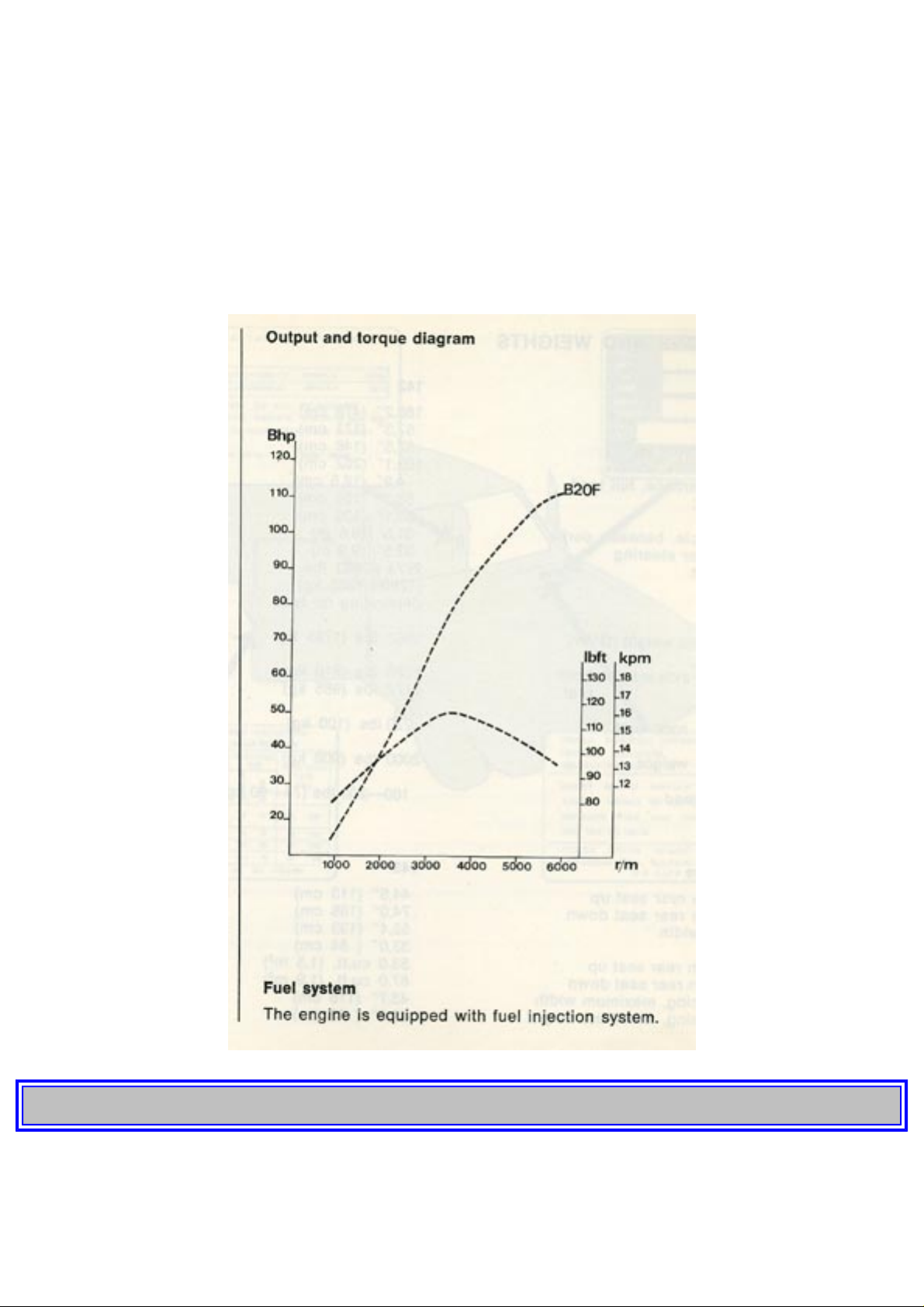
1974 Volvo 142 144 145
Idling speed (warm engine) 900 rpm (800 rpm = BW 35 autom. transmission)
Cooling system
Type Positive pressure 10 psi = (0.7 kp/cm2) closed system
Thermostat, begins to open at 180°F (82° C)
- fully open at 195°F (90° C)
Fan belt, designation HC-38X888
pg. 75 SPECIFICATIONS
Ignition system
Firing order 1-3-4-2
http://new.volvocars.com/ownersdocs/1974/1974%20142%20144%20145/74142144145_04.htm (7 sur 11) [2013-03-14 11:44:30]
Page 77

1974 Volvo 142 144 145
Ignition setting stroboscope setting with vacuum regulator disconnected 10° B.T.D.C. (at 700 rpm)
Spark plugs Bosch W 200 T 35*
- Spark plug gap .028-.032" (.7-.8 mm)
- Tightening torque 25-29 lb ft (3.5-4.0 kpm)
Distributor, direction of rotation Anti-clockwise
- Ignition breaker gap .016-.020" (.4-.5 mm)
ELECTRICAL SYSTEM
Voltage 12V
Battery, type Tudor 6 EX 4F o.p.*
- Capacity 60 Ah
- Electrolyte, specific gravity 1.28
- Recharge at 1.21
Alternator, rated output 770 W
- max. current 55 A
* or corresponding
Lights, 12 volt US bulb No. Power Socket No. of bulbs
Headlights 7" Type 2 Sealed Beam
Parking Lights, front 67 5W S8.5 2
Turn Signals, front 1034 32 cp Ba 15s 2
Turn Signals, rear 1073 32 cp Ba 15s 2
Tail Lights 67 5W Ba 15s 2
Brake Stop Lights 1073 32 cp Ba 15s 2
Back-up Lights 1073 32 cp Ba 15s 2
Side Marker Lights 57 5W S8.5 2
The following bulbs may be obtained from your nearest Volvo dealer:
License Plate Light 5W S8.5 2
Interior Light 10W S8.5 1(145:2)
Glove Locker Light 2W Ba9s 1
Instrument Panel Light 2W W2.2d 3
Lighting, Control Panel 1.2W W1.8d 3
Shift Positions, Autom. Transm. 1.2W W1.8d 1
Warning Lamps:
- Charging 1.2W W1.8d 1
- Turn Signals 1.2W W1.8d 2
http://new.volvocars.com/ownersdocs/1974/1974%20142%20144%20145/74142144145_04.htm (8 sur 11) [2013-03-14 11:44:30]
Page 78

1974 Volvo 142 144 145
- Brakes 1.2W W1.8d 1
- Headlights 1.2W W1.8d 1
- Oil Pressure 1.2W W1.8d 1
- Overdrive 1.2W W1.8d 1
- Warning Flashers 1.2W W1.8d 1
- El. Heated Rear Window 1.2W W1.8d 1
- Tail Gate Wiper/Washer 1.2W W1.8d 1
- Seat Belts 1.2W W1.8d 1
- Bulbs 1.2W W1.8d 1
pg. 76 SPECIFICATIONS
POWER TRANSMISSION
Clutch
Clutch release arm play 3 mm (approx. 1/8")
Transmission
Type designation
Reduction ratios:
M40 M41 BW35
1st speed 3.41:1 3.41:1 2.39:1
x the converter ratio
2nd speed 1.99:1 1.99:1 1.45:1
3rd speed 1.36:1 1.36:1 1:1
4th speed 1:1 1:1 (with overdrive) - 0.80:1 Reverse 3.25:1 3.25:1 2.09:1
Rear axle
Type Hypoid bevel gear
Reduction ratio 4.1:1 4.3:1
Speed in mph (kmph) at 1000 engine rpm
Rear axle 4.1:1 4.3:1
Gearbox M40 M41
1st speed 5.3 ( 8.4) 5.1 ( 8.0)
http://new.volvocars.com/ownersdocs/1974/1974%20142%20144%20145/74142144145_04.htm (9 sur 11) [2013-03-14 11:44:30]
Page 79
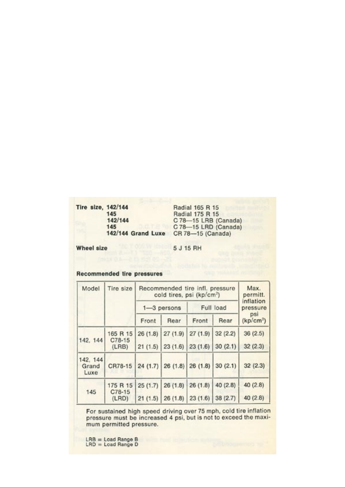
1974 Volvo 142 144 145
2nd speed 9.0 (14.3) 8.5 (13.7)
3rd speed 13.0 (21.0) 12.5(20.0)
4th speed 18.0 (28.6) 17.0 (27.7)
4th speed + overdrive - 21.5 (34.2)
Reverse 5.5 ( 8.8) 5.3 ( 8.4)
FRONT WHEEL ALIGNMENT
The alignment values apply to an
unladen car but include fuel,
coolant and spare wheel.
Toe-in 2-5 mm (1/8")
Camber 0 to + 1/2°
Caster +1 to +2 °
King pin inclination 7.5°
http://new.volvocars.com/ownersdocs/1974/1974%20142%20144%20145/74142144145_04.htm (10 sur 11) [2013-03-14 11:44:30]
Page 80

1974 Volvo 142 144 145
pg. 77 SPECIFICATIONS
CAPACITIES
Fuel tank 15.8 US galls./13.2 Imp. galls. 60 liters
Cooling system
10 US qts./9 Imp. qts. 9.4 liters (of which expansion tank 1 US qt./ 0.5 Imp.
qt. [0.6 liter])
Oil capacity,
- engine, at oil change 3.4 US qts./2.9 Imp. qts. (3.25 liters)
- incl. oil filter 4.0 US qts./3.3 Imp. qts. (3.75 liters)
- transmission (M40) 1.6 US pints/1.3 Imp. pints (0.75 liter)
- (M41) 3.4 US pints/2.8 Imp, pints (1.6 liters)
- (BW35) 13.5 US pints/11.3 Imp. pints (6.4 liters)
rear axle 2.7 US pints/2.3 Imp. pints (1.3 liters)
steering gear, manual 0.5 US pints/0.4 Imp. pints (0.25 liter)
power 2.3 US pints/2.0 Imp. pints (1.1 liters)
TOOL KIT
Wheel nut and spark plug wrench
2 screwdrivers (1 Phillips, 1 standard)
Tommy bar
2 open end wrenches
Top of Page
http://new.volvocars.com/ownersdocs/1974/1974%20142%20144%20145/74142144145_04.htm (11 sur 11) [2013-03-14 11:44:30]
Page 81
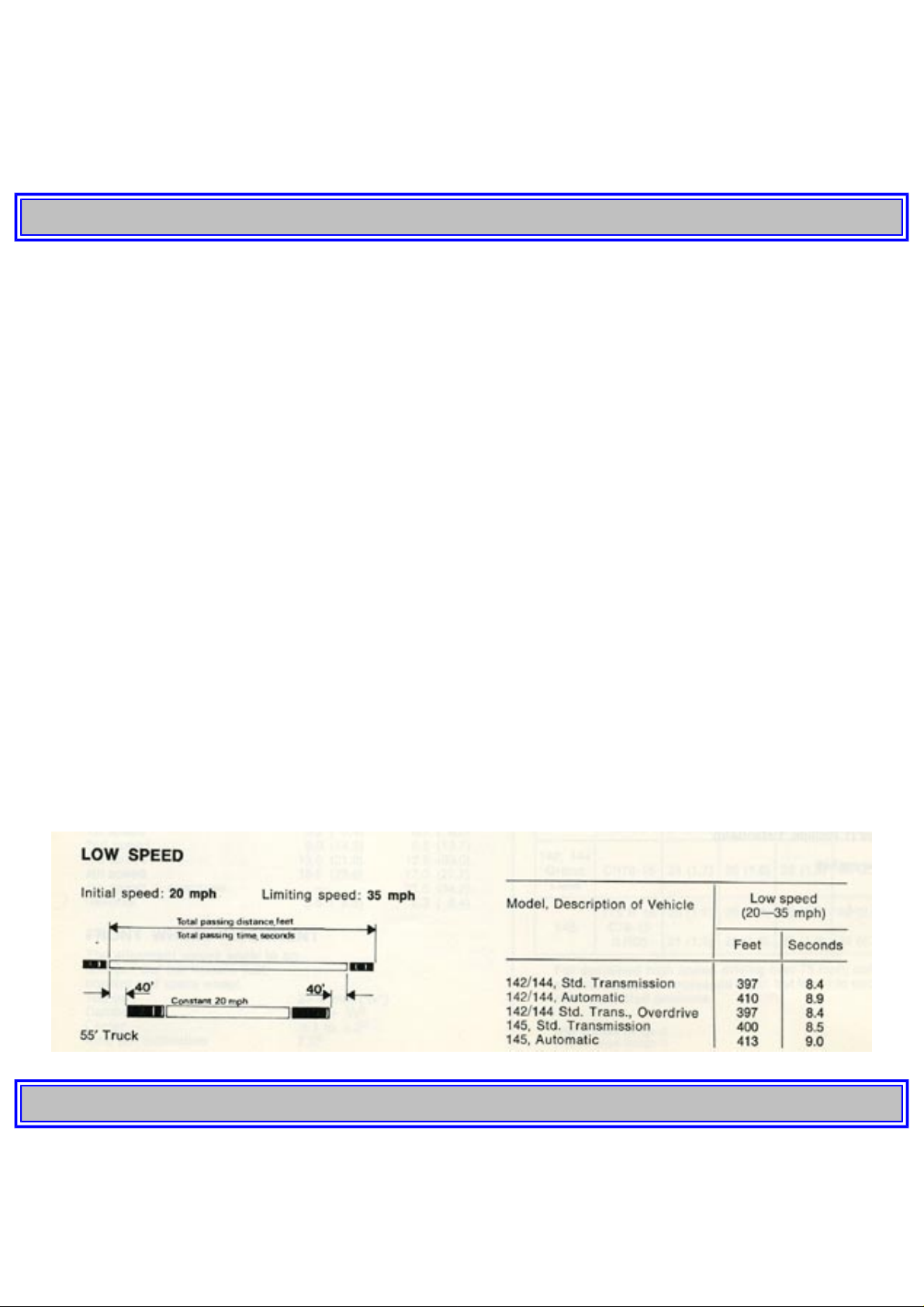
1974 Volvo 142 144 145
1 9 7 4
VOLVO
142 144 145
pg. 78 CONSUMER INFORMATION
CONSUMER INFORMATION
Acceleration and passing ability
Vehicle stopping distance
Tire reserve load
The information about the 1974 Volvo 142, 144 and 145 shown in the following pages is presented in
accordance with Federal requirements for comparison with other makes and models. The exacting test
procedures established by the National Highway Traffic Safety Administration were followed to obtain the
figures.
Notice: The information presented represents results obtainable by skilled drivers under controlled road and
vehicle conditions and the information may not be correct under other conditions.
Acceleration and Passing Ability
This chart indicates passing times and distances that can be met or exceeded by 1974 Volvo 142, 144 and
145 in the situations diagrammed below.
The low-speed pass assumes an initial speed of 20 mph and a limiting speed of 35 mph.
pg. 79 CONSUMER INFORMATION
HIGH SPEED
The high-speed pass assumes an initial speed of 50 mph and a limiting speed of 80 mph.
http://new.volvocars.com/ownersdocs/1974/1974%20142%20144%20145/74142144145_05.htm (1 sur 12) [2013-03-14 11:44:44]
Page 82
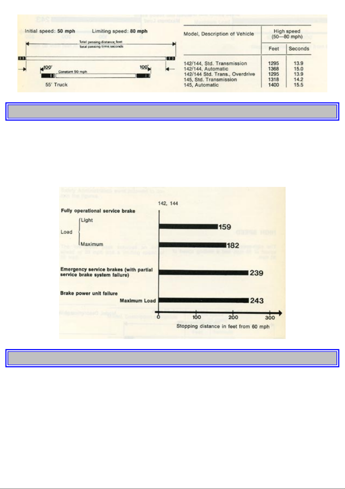
1974 Volvo 142 144 145
pg. 80 CONSUMER INFORMATION
Vehicle Stopping Distance
This chart indicates braking performance that can be met or exceeded by 1974 Volvo 142 and 144 without
locking the wheels, under different conditions of loading and with partial failures of the braking system. The
information presented represents results obtainable by skilled drivers under controlled road and vehicle
conditions, and the information may not be correct under other conditions.
pg. 81 CONSUMER INFORMATION
Vehicle Stopping Distance
This chart indicates braking performance that can be met or exceeded by 1974 Volvo 145 without locking the
wheels, under different conditions of loading and with partial failures of the braking system. The information
presented represents results obtainable by skilled drivers under controlled road and vehicle conditions, and
the information may not be correct under other conditions.
http://new.volvocars.com/ownersdocs/1974/1974%20142%20144%20145/74142144145_05.htm (2 sur 12) [2013-03-14 11:44:44]
Page 83
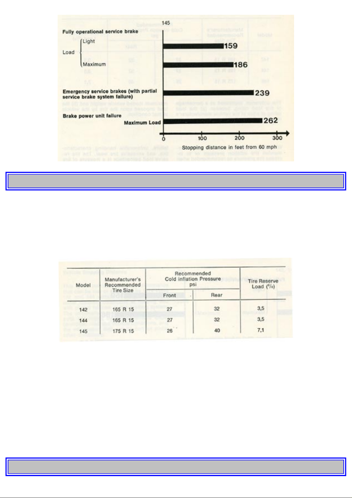
1974 Volvo 142 144 145
pg. 82 CONSUMER INFORMATION
Tire Reserve Load
This chart lists the tire size designations recommended by Volvo for use 1974 142, 144 and 145 with the
recommended inflation pressure for maximum loading and the tire reserve load percentage for each of the
tires listed. The tire reserve load percentage indicated is met or exceeded by each vehicle to which the chart
applies.
The difference, expressed as a percentage of tire load rating, between (a) the load rating of a tire at the
vehicle manufacturer's recommended inflation pressure at the maximum loaded vehicle weight and (b) the
load imposed upon the tire by the vehicle at that condition.
WARNING. Failure to maintain the recommended tire inflation pressure or to increase tire pressure as
recommended when operating at maximum loaded vehicle, or loading the vehicle beyond the capacities
specified on the tire placard affixed to the vehicle, may result in unsafe operating conditions due to premature
tire failure, unfavorable handling characteristics, and excessive tire wear. The tire reserve load percentage is
a measure of tire capacity not of vehicle capacity. Loading beyond the specified vehicle capacity may result
in failure of other vehicle components.
pg. 83
http://new.volvocars.com/ownersdocs/1974/1974%20142%20144%20145/74142144145_05.htm (3 sur 12) [2013-03-14 11:44:44]
Page 84
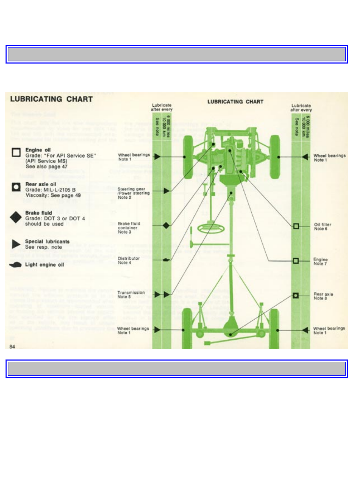
1974 Volvo 142 144 145
This page left intentionally blank.
pg. 84 LUBRICATING CHART
pg. 85 LUBRICATING CHART
Notes to lubricating chart
Note 1. The wheel bearings are packed at the factory with a special type of grease intended to last the entire
lifetime of the bearings. In connection with such workshop operations involving uncovering the wheel
bearings, the bearings should be cleaned and then lubricated with high-class, durable grease according to the
instructions in the service manual. Except on the above occasion, subsequent adding or changing of lubricant
is not required.
Note 2. Manual steering: Check that the oil reaches up to the filler plug. Use hypoid oil SAE 80 all year
round.
http://new.volvocars.com/ownersdocs/1974/1974%20142%20144%20145/74142144145_05.htm (4 sur 12) [2013-03-14 11:44:44]
Page 85

1974 Volvo 142 144 145
Power steering: Check that the oil level in the power steering oil container is 5-10 mm (5/16") above the
level mark. Use Automatic Transmission Fluid. Type A or Dexron.
Note 3. Check that the fluid reaches up to the MAX mark.
Note 4. Lubricate the felt wick under the rotor and fill a few drops of light engine oil into the lubricating cup.
Note 5. Check every 6,000 miles (10,000 km) that the oil reaches up to the filler plug. Concerning oil change,
see
page 50.
NOTE. The type of transmission will decide the type of lubricant used.
Note 6. Change the oil filter every 6,000 miles (10,000 km). See page 51.
Note 7. Check the oil level when filling the tank. Concerning oil changing, see
page 47.
Note 8. Check every 6,000 miles (10,000 km) that the oil reaches up to the filler plug. Concerning lubricant
for rear axle with limited slip differential, see page 49.
Change the oil every 24,000 miles (40,000 km).
Oil capacities
Engine excl. oil filter approx. 3.4 US qts./2.9 Imp. qts. (3.25 liters)
- incl. oil filter approx. 4.0 US qts./3.3 Imp. qts. (3.75 liters)
Transmission - M40 approx. 1.6 US pints/1.3 Imp. pints (0.75 liter)
- M 41 approx. 3.4 US pints/2.8 Imp. pints (1.6 liters)
- BW 35 approx. 13.5 US pints/11.3 Imp. pints (6.4 liters)
Rear axle approx. 2.7 US pints/2.3 Imp. pints (1.3 liters)
Steering gear approx. 0.5 US pints/0.4 Imp. pints (0.25 liter)
pg. 86 INDEX
INDEX
A
Air cleaner
52
Air conditioner
13
All-round lubrication
46
Alternator
57
Anti-freeze agent
65
Automatic transmission, operation
27
http://new.volvocars.com/ownersdocs/1974/1974%20142%20144%20145/74142144145_05.htm (5 sur 12) [2013-03-14 11:44:44]
Page 86

1974 Volvo 142 144 145
Automatic transmission, oil capacity
48
Automatic transmission, oil changing
48
B
Battery, level check
56
Battery, state of charge
56
Body, lubrication
46
Body, washing
63
Brake fluid, level check
50
Brakes, description
40
Brakes, servicing
61, 66
Bulbs
57
Bulb Integrity Sensor
7
C
Capacities
77
Cargo compartment
22, 23
Charging warning light
7
Chassis, maintenance
46
Checking oil levels
47, 48, 49
Cigarette lighter
11
Clutch
34, 76
Cold weather
65
Compression test
53
Consumer Information
78-83
Cooling system, capacity
77
- coolant change
55
- description
34
- level check
54
- topping-up
54
Crankcase ventilation, servicing
51
Cylinder head bolts
50
D
Differential, description
36
- level check
49
- oil capacity, oil change
49
Doors and locks
20, 66
E
http://new.volvocars.com/ownersdocs/1974/1974%20142%20144%20145/74142144145_05.htm (6 sur 12) [2013-03-14 11:44:44]
Page 87

1974 Volvo 142 144 145
Electrical system, description
38
Elec. heated rear window
14
Electrolyte level, check
56
Emergency warning flashers
14
Engine, description
32
- oil changing
47
- servicing
42, 47
Evaporative Control System
52
Exhaust emission control
34
Exhaust Gas Recirculation
53
F
Fan belt
50, 74
Fan switch
12
Federal Clean Air Act (USA)
42
Front end, description
37
Front seats
15
Frozen locks
66
Fuel
56
Fuel filter
51, 52
Fuel gauge
8
Fuel system
33, 52
Fuel tank, capacity
77
Fuses
60
G
Gear shifting
26
Guarantee inspection
3
H
Headlight alignment
56
Headlights, changing
58
Heater and ventilation controls
12
Heating system, description
37
Hood, hood release
10
I
Ignition switch and steering wheel lock
8
Ignition system
54, 75
Injectors
33
http://new.volvocars.com/ownersdocs/1974/1974%20142%20144%20145/74142144145_05.htm (7 sur 12) [2013-03-14 11:44:44]
Page 88

1974 Volvo 142 144 145
Injection system
56
Instruments
5
Instrument light
11
Interior light
21
K
Keys
20
L
License plate light
60
Light switch
5
Locks
20
Lubrication
46
Lubricating chart
84-85
Lubricating system
32
Lumbar support
15
M
Maintenance schedule
44
Measurements and weights
73
O
Odometer
6
Oil capacities
47, 48, 49
Oil change, automatic transmission
48
Oil change, differential
49
Oil change, engine
47
Oil change, transmission
48
Oil change, rear axle
49
Oil change, steering gear
49
Oil filter
51
Output and torque diagram
74
P
Paintwork
64
Paintwork, damage
64
Parking brake
9
Parking lights
59
Polishing and waxing
63
Power steering
50
Power transmission
34
R
http://new.volvocars.com/ownersdocs/1974/1974%20142%20144%20145/74142144145_05.htm (8 sur 12) [2013-03-14 11:44:44]
Page 89

1974 Volvo 142 144 145
Rear axle, description
36
- level check
49
- oil capacity
49
- oil change
49
Rear seat belts
19
Rear view mirror
21
Running-in
24
Rust-protection
64
S
Seat/Ignition Interlock System
8, 14, 18, 25
Seat belts
18, 19
Seat
15
Service Diagnosis
67
Servicing before a long-distance trip
65
Servicing, general
41
Servicing, wintertime
65
Shift positions
27
Spare wheel space
23
Spark plugs
53
Specifications
73
Speedometer
6
Starting in the garage
25
Starting the engine
25
Steering
37
Steering gear, oil check
49
Sun-roof
21
T
Tailgate window
11
Temperature gauge, coolant
7
Throttle valve switch
53
Tires
61, 76
Tire pressure
76
Tools
77
Torque diagram
74
Touch up
64
Towing
29
http://new.volvocars.com/ownersdocs/1974/1974%20142%20144%20145/74142144145_05.htm (9 sur 12) [2013-03-14 11:44:44]
Page 90

1974 Volvo 142 144 145
Trailer hauling
30
Transmission, description
35
Transmission, oil capacity
48
Transmission, oil changing
48
Transmission, oil level check
48
Trip meter
7
Turn signals
10
Type designations
72
U
Underbody treatment
64
Upholstery
64
V
Valve clearances
53
Ventilation controls
12
Viscosities
47, 48, 49
W
Warming up engine
25
Warning lights
6, 7
Washing
63
Waxing
63
Weights
73
Wheels and tires, description
61
Wheels and tires, changing
62
Wheels and tires, servicing
61
Wheels and tires, air pressure
76
Windshield wiper and washer switch
9
Wiring diagrams
38, 39
pg. 88 WHEN FILLING THE TANK
Regular grade of leaded or low-leaded fuel (with an octane rating of at least 91 RON) should be used.
Engine oil level
The oil level should be between the marks on the dipstick. Top up with multi-grade oil.
The distance between the dipstick marks is equivalent to 1 quart (1 liter).
Coolant level
The level should be between the MAX. and MIN. marks on the expansion tank. Top up with a mixture of 50
http://new.volvocars.com/ownersdocs/1974/1974%20142%20144%20145/74142144145_05.htm (10 sur 12) [2013-03-14 11:44:44]
Page 91
1974 Volvo 142 144 145
% anti-freeze/summer coolant and 50% water.
Washer fluid level
The washer fluid container should always be adequately filled (wintertime with water and an anti-freeze
solvent).
Brake fluid level
The level can be checked without removing the cap. The level should be above the MIN. mark on the
transparent fluid container. Top up with brake fluid, designation DOT 3 or DOT 4 (previously SAE J 1703).
pg. 89 BACK INSIDE COVER
http://new.volvocars.com/ownersdocs/1974/1974%20142%20144%20145/74142144145_05.htm (11 sur 12) [2013-03-14 11:44:44]
Page 92
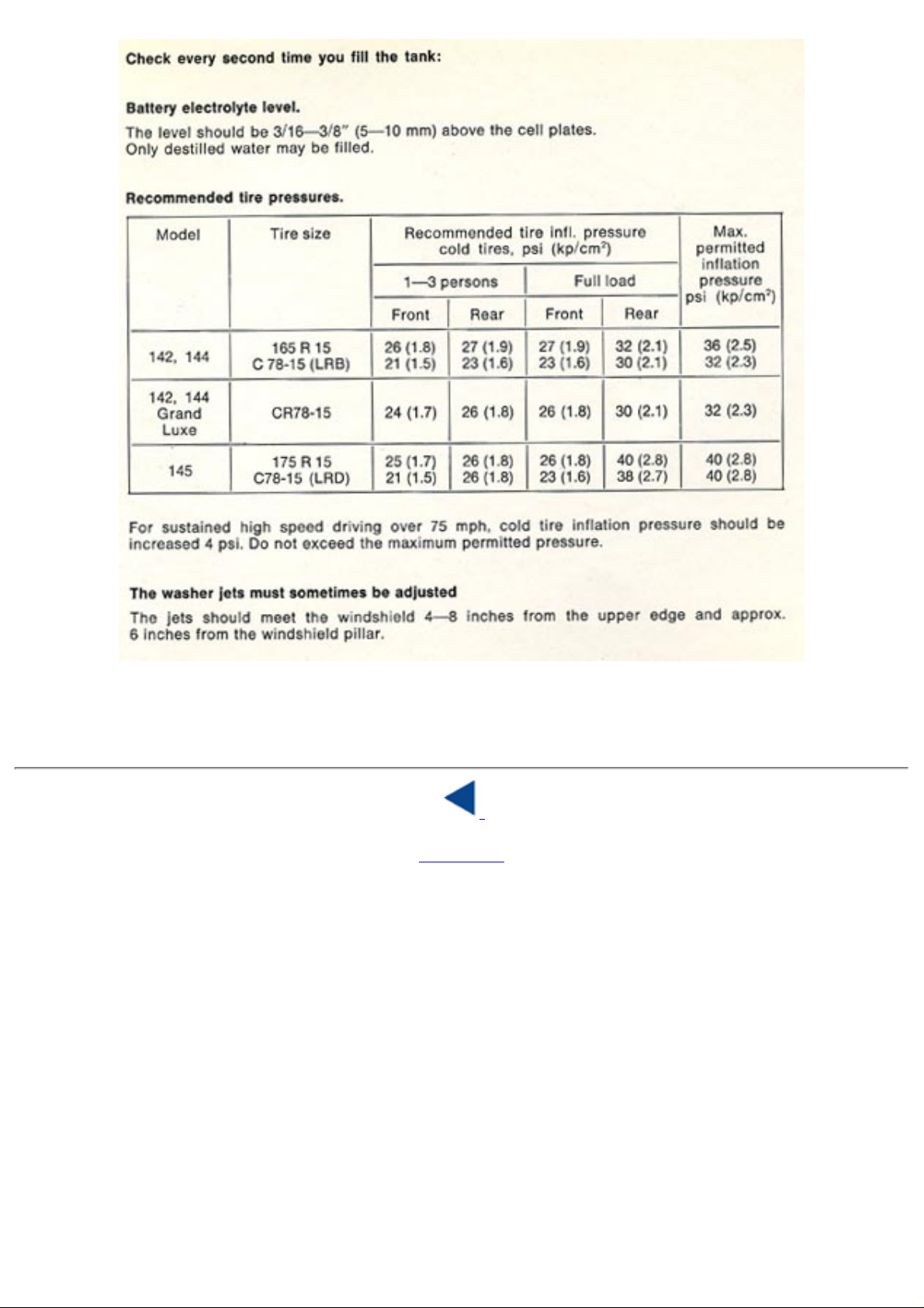
1974 Volvo 142 144 145
Top of Page
http://new.volvocars.com/ownersdocs/1974/1974%20142%20144%20145/74142144145_05.htm (12 sur 12) [2013-03-14 11:44:44]
 Loading...