


Service.
Self-study programme 307
The Touran Electrical system
Design and function

The networking technology, used until now only in luxury class vehicles, will be a feature in compact vans, such as the Volkswagen Touran.
The control units installed in this system also manage tasks that were previously carried out by relays and switches. In order that these tasks can be fulfilled efficiently, the units have to exchange a great deal of information (data) between each other. Such a high rate of data transfer would only be possible with a large number of cables if standard means were used, such as wiring connections.
To keep the number of wiring connections at a manageable level, Volkswagen favours the use of data bus connections on a wider scale.
This self-study programme is designed to help you better understand the networking concept of the Volkswagen Touran.
It covers the allocation of control units to the various data bus systems, the fitting locations of relay slots, fuses and control units. Furthermore, it describes the various functions of and changes to the diagnosis system.
|
S307_050 |
NEW |
Important |
|
Note |
|
|
|
|
|
|
This self-study programme explains the design |
For the latest testing, setting and repair |
|
|
|
|
and function of new developments. |
instructions, please refer to the relevant |
|
|
|
|
The contents will not be updated. |
workshop literature. |
|
|
|
|
2

Contents
Introduction . . . . . . . . . . . . . . . . . . . . . . . . . . . . . . . . . . . . . . 4
LIN data bus . . . . . . . . . . . . . . . . . . . . . . . . . . . . . . . . . . . . 16
Onboard power supply . . . . . . . . . . . . . . . . . . . . . . . . . . . 20
Data bus diagnosis interface . . . . . . . . . . . . . . . . . . . . . . 24
Onboard power supply control unit . . . . . . . . . . . . . . . . . 28
Windscreen wiper system. . . . . . . . . . . . . . . . . . . . . . . . . . 38
Rear window wiper system . . . . . . . . . . . . . . . . . . . . . . . . 44
Dash panel insert . . . . . . . . . . . . . . . . . . . . . . . . . . . . . . . . 46
Immobiliser . . . . . . . . . . . . . . . . . . . . . . . . . . . . . . . . . . . . . 50
Convenience and infotainment settings . . . . . . . . . . . . . . 54
Lighting . . . . . . . . . . . . . . . . . . . . . . . . . . . . . . . . . . . . . . . . 55
Service . . . . . . . . . . . . . . . . . . . . . . . . . . . . . . . . . . . . . . . . . 56
Test yourself . . . . . . . . . . . . . . . . . . . . . . . . . . . . . . . . . . . . 58
3
Introduction
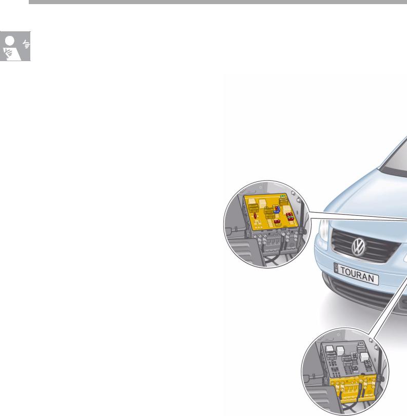
Fuse boxes and relay slots in vehicle's electrical system
Fitting locations
The onboard power supply of the Touran is decentralised. For this reason, the fuse boxes and relay slots are installed at various locations in the vehicle.
The adjacent diagram shows the various fitting locations.
Electrics box on left
in engine compartment
Back-up fuse box on left in engine compartment
4

Relay carrier on
left under dash panel
Relay carrier on onboard power supply control unit on left under dash panel
Fuse box on
left under dash panel
S307_001
5
Introduction
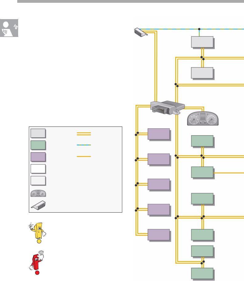
The networking concept
Overview of networked control units |
|
In order that data can be transferred between |
T16 |
the control units, these are networked via various data bus systems.
The data bus diagnosis interface J533 (gateway) provides the interface for the data buses:
- Drive train CAN data bus
- Convenience CAN data bus - Infotainment CAN data bus
- Dash panel insert CAN data bus - Diagnosis CAN data bus
Drive train |
CAN data bus |
CAN data bus |
line |
Convenience |
Communi- |
CAN data bus |
cations line |
Infotainment |
LIN data bus |
CAN data bus |
line |
LIN data bus |
|
CAN data bus |
|
Sensor |
|
Dash panel insert |
|
CAN data bus |
|
Diagnosis CAN |
|
data bus |
|
|
S307_049 |
In addition to the CAN data bus,
a number of electric components are networked via the LIN data bus.
The data protocols have been changed. Therefore, these control units cannot be exchanged with those of other vehicle models e.g. Touareg or Phaeton.
J533
J503 R
J412
J525
J162
R78
J220
J431
J285
J345
J519
J255
J136
J604
J388
6

G419
J217 |
J104 |
J587 |
J500 |
J234 |
G85 |
E221
J446 |
J527 |
J400 J584
J386 |
J387 |
|
J393 |
J389 |
G273 |
H8 |
G384 |
S307_002
Key |
|
|
E221 |
Operating unit in steering wheel |
|
G85 |
Steering angle sender |
|
G273 |
Interior monitoring sensor |
|
G384 |
Vehicle inclination sensor |
|
|
||
G419 |
ESP sensor unit |
|
H8 |
Anti-theft alarm signal horn |
|
J104 |
ABS with EDL control unit |
|
J136 |
Seat adjustment control unit |
|
J162 |
Heating control unit |
|
J217 |
Autom. gearbox control unit |
|
J220 |
Motronic control unit |
|
J234 |
Airbag control unit |
|
J255 |
Climatronic control unit |
|
J285 |
Control unit with display in dash |
|
|
panel insert |
|
J345 |
Trailer detector control unit |
|
J386 |
Door control unit, driver side |
|
J387 |
Door control unit, front passenger side |
|
J388 |
Door control unit, rear left |
|
J389 |
Door control unit, rear right |
|
J393 |
Convenience system central control unit |
|
J400 |
Wiper motor control unit |
|
J412 Cellphone electronics control unit |
|
|
J431 |
Headlight range control, control unit |
|
J446 |
Parking aid control unit |
J500 |
Power steering control unit |
J503 |
Control unit with display for radio and |
|
navigation |
J519 |
Onboard power supply control unit |
J525 |
Digital sound package control unit |
J527 |
Steering column electronics control unit |
J533 |
data bus diagnosis interface |
J584 |
Wiper motor control unit |
|
front passenger side |
J587 |
Selector lever sensors control unit |
J604 |
Auxiliary air heater control unit |
R |
Radio |
R78 |
TV tuner |
T16 |
Diagnosis connection |
7

Introduction
Control units in drive train CAN data bus
Control units and fitting locations
The adjacent diagram shows the control
units that belong to the drive train CAN data bus and associated fitting locations.
The data is transferred at a speed of 500 kbit/s. Transfer is made via the orange/black
CAN high line and orange/brown CAN low line. To make data transfer more efficient,
the CAN lines are entwined.
Airbag control unit J234 under centre console
ABS with EDL control unit J104 under bulkhead in
engine compartment
Motronic control unit J220 under plenum chamber cover
8

Control unit for
headlight range control J431 on left under dash panel, on tunnel support
data bus diagnosis interface J533 under dash panel,
above relay carrier
S307_003
Automatic gearbox control unit J217 in wheel housing
9

Introduction
The control units in the drive train CAN data bus
Control units and fitting locations
Shown in the diagram are the control units
of the convenience CAN data bus and their fitting locations.
The speed of data transfer is 100 kbit/s.
The data is transferred via the orange/green
CAN high line and orange/brown CAN low line.
Both CAN lines are entwined together.
Steering column electronics control unit J527 on steering column switch
Convenience system central control unit J393
on right under dash panel, near centre console
Climatronic control unit J255 in centre console
10

Parking aid control unit J446 in rear right side part
data bus diagnosis interface J533 under dash panel,
above relay carrier
Trailer detector control unit J345 in rear right side part
Onboard power supply control unit J519 under dash panel, on relay carrier
Door control units J386, J387, J388, J389 in doors
S307_004
11

Introduction
The control units in the infotainment CAN data bus
Control units and fitting locations
The control units of the CAN data bus and fitting locations are shown in the adjacent diagram.
The infotainment CAN data bus transfers data at a rate of 100 kbit/s. The CAN high line is orange/purple and the CAN low line is orange/brown.
Both CAN lines are entwined together.
Cellphone operating electronics control unit J412
on front right in footwell
Heater control unit J162 on front right under wing
12

Control unit with display
for radio and navigation J503 or Radio R
in centre console
S307_005
13
Introduction
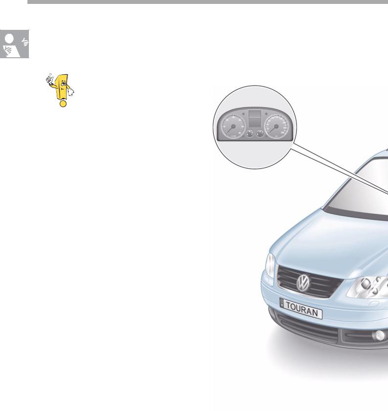
The control units in the dash panel insert CAN data bus and in the diagnosis CAN data bus
The dash panel insert CAN data bus and the diagnosis CAN data bus are new data bus connections in the Volkswagen Touran.
Dash panel insert CAN data bus
The data bus transfers data from the
dash panel insert to the data bus diagnosis interface. The control unit with display unit in the dash panel insert and the data bus diagnosis interface are the only control
units attached to this data bus.
Diagnosis CAN data bus
Data transfer between the diagnosis connection T16 and the data bus diagnosis interface is via the diagnosis CAN data bus.
Rate of data transfer
The rate at which data is transferred is 500 kbit/s for both CAN data buses.
Control unit with display unit in dash panel J285
14

data bus diagnosis interface J533 under dash panel,
above relay carrier
S307_006
T16 Diagnosis connection on left in footwell
15

LIN data bus
The LIN data bus as sub data bus system
General description
A sub data bus system connects control units with their electrical components. Among these components are, for example, control units, switches, sensors, actuators etc. This type of connection and data transfer is used in the Volkswagen Touran for a number of systems.
As a sub data bus system, the LIN data bus has an advantage in cost.
The designation LIN stands for local interconnect network, and it means that all the associated electrical components are within a set and limited area of the vehicle.
It is possible for a number of LIN data bus systems to be installed in a vehicle. They will each have different functions to perform.
A LIN data bus system consists of a master control unit and one or more slave control units.
The master control unit is also networked with other control units (apart from slave control units) in the vehicle via the CAN data bus. This permits the transfer of data to other LIN data bus systems and other CAN data bus control units.
LIN data bus system
data bus diagnosis interface J533
LIN data bus
CAN bus
Convenience system central control unit
J393
CAN user and LIN master
Anti-theft alarm system horn H8 LIN slave
Interior monitoring sensor G273 LIN slave
Vehicle inclination sender G384 LIN slave
S307_007
16
Data transfer
The data is transferred at a speed of 1 kbit/s to 20 kbit/s.
The rate of data transfer is therefore a maximum of 20% of the rate for convenience or infotainment CAN data buses and is fixed
in the software of the LIN master.
This transfer is made via data leads that are violet in basic colour with a white identification mark. The cross section of the wire is 0.35 mm2. The LIN data bus is a single wire bus. The data lead is not screened.
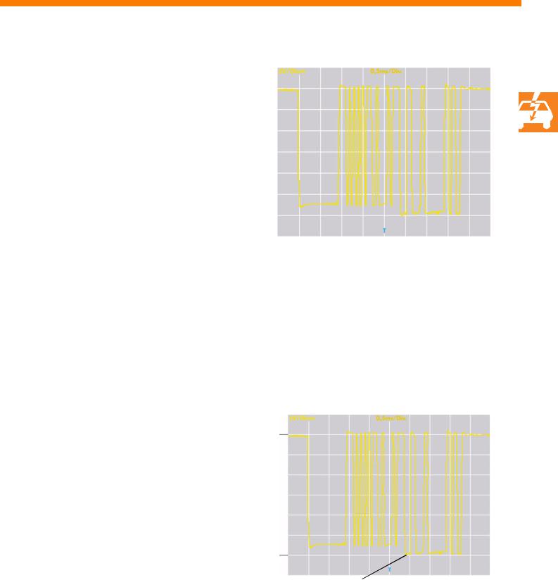
Signal level
The signal level of the LIN data buses is either close to battery voltage (UB) (recessive level) or earth (0 Volt) (dominant level).
S307_008
Recessive level
U
UB
0
Dominant level |
t |
|
S307_009 |
||
|
17
LIN data bus
Master control unit
The control unit connected via the CAN data bus system performs the master functions
in the LIN data bus system.
Among these master functions are:
-Data conversion of LIN data bus messages to the data format used by the CAN data buses, if and when these messages are required.
-The control of data transfer in the
LIN data bus and monitoring of the data transfer rate.
-The transfer of diagnosis data to the LIN slave control unit.
The transfer of data between master and slave is always initialised by the master. A slave is not capable of communicating independently.
Master control unit
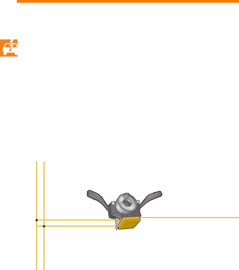
Steering column electronics control unit J527 Users of convenience CAN data bus and master control unit in the LIN data bus
18
 Loading...