

Volkswagen Jetta 2006 User Manual

P
r
o
t
e
c
t
e
d
b
y
c
o
p
y
r
i
g
h
t
.
C
o
p
y
i
n
g
f
o
r
p
r
i
v
a
t
e
o
r
c
o
m
m
e
r
c
i
a
l
p
u
r
p
o
s
e
s
,
i
n
p
a
r
t
o
r
i
n
w
h
o
l
e
,
i
s
n
o
t
p
e
r
m
i
t
t
e
d
u
n
l
e
s
s
a
u
t
h
o
r
i
s
e
d
b
y
V
o
l
k
s
w
a
g
e
n
A
G
.
V
o
l
k
s
w
a
g
e
n
A
G
d
o
e
s
n
o
t
g
u
a
r
a
n
t
e
e
o
r
a
c
c
e
p
t
a
n
y
l
i
a
b
i
l
i
t
y
w
i
t
h
r
e
s
p
e
c
t
t
o
t
h
e
c
o
r
r
e
c
t
n
e
s
s
o
f
i
n
f
o
r
m
a
t
i
o
n
i
n
t
h
i
s
d
o
c
u
m
e
n
t
.
C
o
p
y
r
i
g
h
t
b
y
V
o
l
k
s
w
a
g
e
n
A
G
.
Service
Workshop Manual
Jetta 2006 ➤
Golf Variant 2008 ➤
6-speed manual gearbox 0AG
Edition 08.2007
Service Department. Technical Information

P
r
o
t
e
c
t
e
d
b
y
c
o
p
y
r
i
g
h
t
.
C
o
p
y
i
n
g
f
o
r
p
r
i
v
a
t
e
o
r
c
o
m
m
e
r
c
i
a
l
p
u
r
p
o
s
e
s
,
i
n
p
a
r
t
o
r
i
n
w
h
o
l
e
,
i
s
n
o
t
p
e
r
m
i
t
t
e
d
u
n
l
e
s
s
a
u
t
h
o
r
i
s
e
d
b
y
V
o
l
k
s
w
a
g
e
n
A
G
.
V
o
l
k
s
w
a
g
e
n
A
G
d
o
e
s
n
o
t
g
u
a
r
a
n
t
e
e
o
r
a
c
c
e
p
t
a
n
y
l
i
a
b
i
l
i
t
y
w
i
t
h
r
e
s
p
e
c
t
t
o
t
h
e
c
o
r
r
e
c
t
n
e
s
s
o
f
i
n
f
o
r
m
a
t
i
o
n
i
n
t
h
i
s
d
o
c
u
m
e
n
t
.
C
o
p
y
r
i
g
h
t
b
y
V
o
l
k
s
w
a
g
e
n
A
G
.
Service
List of Workshop Manual Repair GroupsList of Workshop Manual
Repair GroupsList of Workshop Manual Repair Groups
Re pa ir G ro up
00 - Technical data
30 - Clutch
34 - Controls, housing
35 - Gears, shafts
39 - Final drive - differential
Technical information should always be available to the foremen and mechanics, because their
careful and constant adherence to the instructions is essential to ensure vehicle road-worthiness and
safety. In addition, the normal basic safety precautions for working on motor vehicles must, as a
matter of course, be observed.
All rights reserved.
No reproduction without prior agreement from publisher.
Copyright © 2010 Volkswagen AG, Wolfsburg MEX5R007720

P
r
o
t
e
c
t
e
d
b
y
c
o
p
y
r
i
g
h
t
.
C
o
p
y
i
n
g
f
o
r
p
r
i
v
a
t
e
o
r
c
o
m
m
e
r
c
i
a
l
p
u
r
p
o
s
e
s
,
i
n
p
a
r
t
o
r
i
n
w
h
o
l
e
,
i
s
n
o
t
p
e
r
m
i
t
t
e
d
u
n
l
e
s
s
a
u
t
h
o
r
i
s
e
d
b
y
V
o
l
k
s
w
a
g
e
n
A
G
.
V
o
l
k
s
w
a
g
e
n
A
G
d
o
e
s
n
o
t
g
u
a
r
a
n
t
e
e
o
r
a
c
c
e
p
t
a
n
y
l
i
a
b
i
l
i
t
y
w
i
t
h
r
e
s
p
e
c
t
t
o
t
h
e
c
o
r
r
e
c
t
n
e
s
s
o
f
i
n
f
o
r
m
a
t
i
o
n
i
n
t
h
i
s
d
o
c
u
m
e
n
t
.
C
o
p
y
r
i
g
h
t
b
y
V
o
l
k
s
w
a
g
e
n
A
G
.
00 - Technical data . . . . . . . . . . . . . . . . . . . . . . . . . . . . . . . . . . . . . . . . . . . . . . . . . . . . 1
30 - Clutch . . . . . . . . . . . . . . . . . . . . . . . . . . . . . . . . . . . . . . . . . . . . . . . . . . . . . . . . . . 9
1 Gearbox identification . . . . . . . . . . . . . . . . . . . . . . . . . . . . . . . . . . . . . . . . . . . . . . . . . . . . . . 1
1.1 Location on gearbox . . . . . . . . . . . . . . . . . . . . . . . . . . . . . . . . . . . . . . . . . . . . . . . . . . . . . . 1
1.2 Identification codes, assembly allocation, capacities . . . . . . . . . . . . . . . . . . . . . . . . . . . . . . 1
2 Overview - power transmission . . . . . . . . . . . . . . . . . . . . . . . . . . . . . . . . . . . . . . . . . . . . . . 3
3 Calculating overall gear ratio “i” . . . . . . . . . . . . . . . . . . . . . . . . . . . . . . . . . . . . . . . . . . . . . . 5
4 General repair notes . . . . . . . . . . . . . . . . . . . . . . . . . . . . . . . . . . . . . . . . . . . . . . . . . . . . . . 6
4.1 Components . . . . . . . . . . . . . . . . . . . . . . . . . . . . . . . . . . . . . . . . . . . . . . . . . . . . . . . . . . . . 6
1 Fault finding, power transmission . . . . . . . . . . . . . . . . . . . . . . . . . . . . . . . . . . . . . . . . . . . . 9
2 Repairing clutch mechanism . . . . . . . . . . . . . . . . . . . . . . . . . . . . . . . . . . . . . . . . . . . . . . . . 10
2.1 Overview . . . . . . . . . . . . . . . . . . . . . . . . . . . . . . . . . . . . . . . . . . . . . . . . . . . . . . . . . . . . . . 10
2.2 Assembly overview - pedal cluster . . . . . . . . . . . . . . . . . . . . . . . . . . . . . . . . . . . . . . . . . . . . 11
2.3 Removing and installing over-centre spring . . . . . . . . . . . . . . . . . . . . . . . . . . . . . . . . . . . . 12
2.4 Removing and installing clutch pedal . . . . . . . . . . . . . . . . . . . . . . . . . . . . . . . . . . . . . . . . . . 14
2.5 Removing and installing mounting bracket . . . . . . . . . . . . . . . . . . . . . . . . . . . . . . . . . . . . . . 16
2.6 Removing and installing master cylinder . . . . . . . . . . . . . . . . . . . . . . . . . . . . . . . . . . . . . . 19
2.7 Removing and installing clutch position sender G476 . . . . . . . . . . . . . . . . . . . . . . . . . . . . 21
2.8 Assembly overview - hydraulic system . . . . . . . . . . . . . . . . . . . . . . . . . . . . . . . . . . . . . . . . 24
2.9 Removing and installing slave cylinder . . . . . . . . . . . . . . . . . . . . . . . . . . . . . . . . . . . . . . . . 25
6-speed manual gearbox 0AG - Edition 08.2007
Contents
Jetta 2006 ➤ , Golf Variant 2008 ➤
2.10 Bleeding clutch system . . . . . . . . . . . . . . . . . . . . . . . . . . . . . . . . . . . . . . . . . . . . . . . . . . . . 27
3 Repairing clutch release mechanism . . . . . . . . . . . . . . . . . . . . . . . . . . . . . . . . . . . . . . . . . . 29
4 Repairing clutch . . . . . . . . . . . . . . . . . . . . . . . . . . . . . . . . . . . . . . . . . . . . . . . . . . . . . . . . . . 31
34 - Controls, housing . . . . . . . . . . . . . . . . . . . . . . . . . . . . . . . . . . . . . . . . . . . . . . . . . . 34
1 Fault finding, power transmission . . . . . . . . . . . . . . . . . . . . . . . . . . . . . . . . . . . . . . . . . . . . 34
2 Repairing selector mechanism . . . . . . . . . . . . . . . . . . . . . . . . . . . . . . . . . . . . . . . . . . . . . . 35
2.1 Installation position of selector mechanism . . . . . . . . . . . . . . . . . . . . . . . . . . . . . . . . . . . . 35
2.2 Removing and installing selector lever knob and cover . . . . . . . . . . . . . . . . . . . . . . . . . . . . 38
2.3 Removing and installing gaiter with selector lever knob and noise insulation . . . . . . . . . . 38
2.4 Repairing selector lever and selector lever housing (through 10.06) . . . . . . . . . . . . . . . . . . 40
2.5 Repairing selector lever and selector lever housing (from 11.06) . . . . . . . . . . . . . . . . . . . . 42
2.6 Assembly overview - removing and installing selector cables . . . . . . . . . . . . . . . . . . . . . . 47
2.7 Plastic relay lever . . . . . . . . . . . . . . . . . . . . . . . . . . . . . . . . . . . . . . . . . . . . . . . . . . . . . . . . 50
2.8 Removing and installing selector mechanism . . . . . . . . . . . . . . . . . . . . . . . . . . . . . . . . . . 51
2.9 Adjusting selector mechanism . . . . . . . . . . . . . . . . . . . . . . . . . . . . . . . . . . . . . . . . . . . . . . 54
3 Removing and installing gearbox . . . . . . . . . . . . . . . . . . . . . . . . . . . . . . . . . . . . . . . . . . . . 57
3.1 Removing gearbox . . . . . . . . . . . . . . . . . . . . . . . . . . . . . . . . . . . . . . . . . . . . . . . . . . . . . . . . 58
3.2 Installing gearbox . . . . . . . . . . . . . . . . . . . . . . . . . . . . . . . . . . . . . . . . . . . . . . . . . . . . . . . . 63
3.3 Torque settings . . . . . . . . . . . . . . . . . . . . . . . . . . . . . . . . . . . . . . . . . . . . . . . . . . . . . . . . . . 68
4 Checking gear oil . . . . . . . . . . . . . . . . . . . . . . . . . . . . . . . . . . . . . . . . . . . . . . . . . . . . . . . . 70
5 Dismantling and assembling gearbox . . . . . . . . . . . . . . . . . . . . . . . . . . . . . . . . . . . . . . . . 72
5.1 Overview - gearbox . . . . . . . . . . . . . . . . . . . . . . . . . . . . . . . . . . . . . . . . . . . . . . . . . . . . . . 72
5.2 Assembly overview . . . . . . . . . . . . . . . . . . . . . . . . . . . . . . . . . . . . . . . . . . . . . . . . . . . . . . . . 73
5.3 Assembly overview - removing and installing cover for gearbox housing and 5th and 6th
gear . . . . . . . . . . . . . . . . . . . . . . . . . . . . . . . . . . . . . . . . . . . . . . . . . . . . . . . . . . . . . . . . . . 74
5.4 Assembly overview - removing and installing clutch housing . . . . . . . . . . . . . . . . . . . . . . . . 76
5.5 Assembly overview - removing and installing input shaft, output shaft (drive pinion),
5.6 Dismantling and assembling procedure . . . . . . . . . . . . . . . . . . . . . . . . . . . . . . . . . . . . . . . . 78
differential, selector mechanism and selector forks . . . . . . . . . . . . . . . . . . . . . . . . . . . . . . 77
Contents i

P
r
o
t
e
c
t
e
d
b
y
c
o
p
y
r
i
g
h
t
.
C
o
p
y
i
n
g
f
o
r
p
r
i
v
a
t
e
o
r
c
o
m
m
e
r
c
i
a
l
p
u
r
p
o
s
e
s
,
i
n
p
a
r
t
o
r
i
n
w
h
o
l
e
,
i
s
n
o
t
p
e
r
m
i
t
t
e
d
u
n
l
e
s
s
a
u
t
h
o
r
i
s
e
d
b
y
V
o
l
k
s
w
a
g
e
n
A
G
.
V
o
l
k
s
w
a
g
e
n
A
G
d
o
e
s
n
o
t
g
u
a
r
a
n
t
e
e
o
r
a
c
c
e
p
t
a
n
y
l
i
a
b
i
l
i
t
y
w
i
t
h
r
e
s
p
e
c
t
t
o
t
h
e
c
o
r
r
e
c
t
n
e
s
s
o
f
i
n
f
o
r
m
a
t
i
o
n
i
n
t
h
i
s
d
o
c
u
m
e
n
t
.
C
o
p
y
r
i
g
h
t
b
y
V
o
l
k
s
w
a
g
e
n
A
G
.
Jetta 2006 ➤ , Golf Variant 2008 ➤
6-speed manual gearbox 0AG - Edition 08.2007
6 Repairing gearbox housing and clutch housing . . . . . . . . . . . . . . . . . . . . . . . . . . . . . . . . . . 91
7 Repairing gearbox housing cover . . . . . . . . . . . . . . . . . . . . . . . . . . . . . . . . . . . . . . . . . . . . 96
8 Repairing selector unit . . . . . . . . . . . . . . . . . . . . . . . . . . . . . . . . . . . . . . . . . . . . . . . . . . . . 99
9 Dismantling and assembling selector forks . . . . . . . . . . . . . . . . . . . . . . . . . . . . . . . . . . . . 102
35 - Gears, shafts . . . . . . . . . . . . . . . . . . . . . . . . . . . . . . . . . . . . . . . . . . . . . . . . . . . . 107
1 Input shaft . . . . . . . . . . . . . . . . . . . . . . . . . . . . . . . . . . . . . . . . . . . . . . . . . . . . . . . . . . . . . . 107
1.1 Dismantling and assembling input shaft . . . . . . . . . . . . . . . . . . . . . . . . . . . . . . . . . . . . . . . . 107
2 Output shaft . . . . . . . . . . . . . . . . . . . . . . . . . . . . . . . . . . . . . . . . . . . . . . . . . . . . . . . . . . . . 117
2.1 Dismantling and assembling output shaft . . . . . . . . . . . . . . . . . . . . . . . . . . . . . . . . . . . . . . 117
39 - Final drive - differential . . . . . . . . . . . . . . . . . . . . . . . . . . . . . . . . . . . . . . . . . . . . . . 125
1 Renewing flange shaft oil seals with gearbox installed . . . . . . . . . . . . . . . . . . . . . . . . . . . . 125
1.1 Renewing oil seal for left flange shaft . . . . . . . . . . . . . . . . . . . . . . . . . . . . . . . . . . . . . . . . . . 125
1.2 Renewing seal for right flange shaft . . . . . . . . . . . . . . . . . . . . . . . . . . . . . . . . . . . . . . . . . . 127
2 Differential . . . . . . . . . . . . . . . . . . . . . . . . . . . . . . . . . . . . . . . . . . . . . . . . . . . . . . . . . . . . . . 129
2.1 Dismantling and assembling differential . . . . . . . . . . . . . . . . . . . . . . . . . . . . . . . . . . . . . . . . 129
2.2 Adjusting differential . . . . . . . . . . . . . . . . . . . . . . . . . . . . . . . . . . . . . . . . . . . . . . . . . . . . . . 137
ii Contents

P
r
o
t
e
c
t
e
d
b
y
c
o
p
y
r
i
g
h
t
.
C
o
p
y
i
n
g
f
o
r
p
r
i
v
a
t
e
o
r
c
o
m
m
e
r
c
i
a
l
p
u
r
p
o
s
e
s
,
i
n
p
a
r
t
o
r
i
n
w
h
o
l
e
,
i
s
n
o
t
p
e
r
m
i
t
t
e
d
u
n
l
e
s
s
a
u
t
h
o
r
i
s
e
d
b
y
V
o
l
k
s
w
a
g
e
n
A
G
.
V
o
l
k
s
w
a
g
e
n
A
G
d
o
e
s
n
o
t
g
u
a
r
a
n
t
e
e
o
r
a
c
c
e
p
t
a
n
y
l
i
a
b
i
l
i
t
y
w
i
t
h
r
e
s
p
e
c
t
t
o
t
h
e
c
o
r
r
e
c
t
n
e
s
s
o
f
i
n
f
o
r
m
a
t
i
o
n
i
n
t
h
i
s
d
o
c
u
m
e
n
t
.
C
o
p
y
r
i
g
h
t
b
y
V
o
l
k
s
w
a
g
e
n
A
G
.
00 – Technical data
1 Gearbox identification
The 6-speed manual gearbox 0AG is installed in the Jetta 2006 ▸
and Golf Variant 2008 ▸ in conjunction with a 4-cylinder engine.
Allocation ⇒ page 1
1.1 Location on gearbox
Code letters and date of manufacture -arrow 1- manual gearbox
0AG -arrow 2-
Manual gearbox 0AG -arrow 2-
Identification code and date of gearbox manufacture -arrow-
Example: GVV 11 12 3
I I I I
I I I I
Identification
code
Day Month Year (2003) of
manufacture
Jetta 2006 ➤ , Golf Variant 2008 ➤
6-speed manual gearbox 0AG - Edition 08.2007
Additional data provide information about the production facility.
Note
The gearbox code also appears on the vehicle identification
plates.
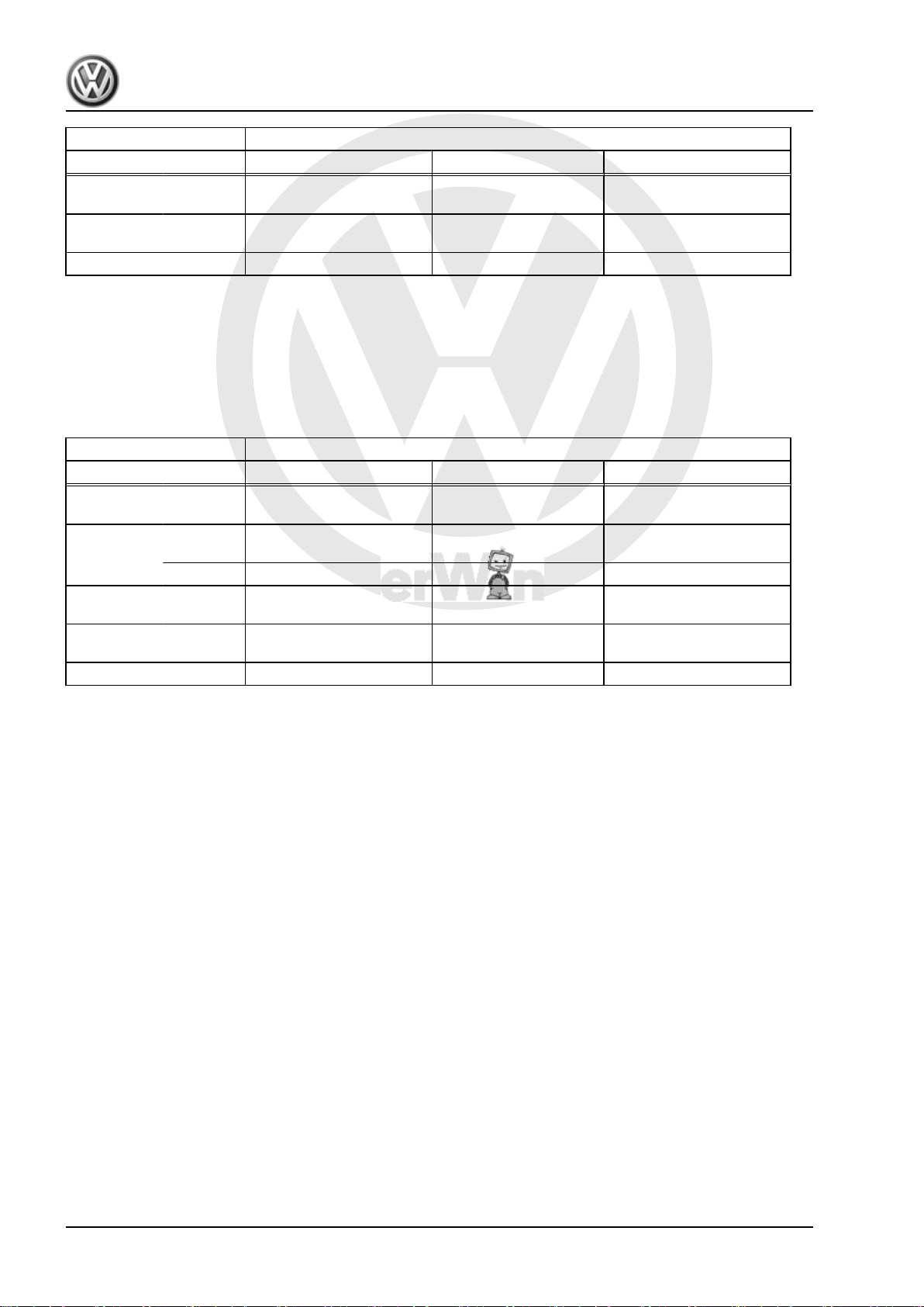
1.2 Identification codes, assembly allocation, capacities
Manual gearbox 6-speed 0AG
Identification code GAJ GMW GVV
Manufac‐
tured
Allocation Model Jetta 2006 ▸ Jetta 2006 ▸ Jetta 2006 ▸
from
to
08.05
08.05
08.05
08.05
08.05
08.05
Engine 1.6 l - 85 kW 1.6 l - 85 kW 1.6 l - 85 kW
1. Gearbox identification 1
P
r
o
t
e
c
t
e
d
b
y
c
o
p
y
r
i
g
h
t
.
C
o
p
y
i
n
g
f
o
r
p
r
i
v
a
t
e
o
r
c
o
m
m
e
r
c
i
a
l
p
u
r
p
o
s
e
s
,
i
n
p
a
r
t
o
r
i
n
w
h
o
l
e
,
i
s
n
o
t
p
e
r
m
i
t
t
e
d
u
n
l
e
s
s
a
u
t
h
o
r
i
s
e
d
b
y
V
o
l
k
s
w
a
g
e
n
A
G
.
V
o
l
k
s
w
a
g
e
n
A
G
d
o
e
s
n
o
t
g
u
a
r
a
n
t
e
e
o
r
a
c
c
e
p
t
a
n
y
l
i
a
b
i
l
i
t
y
w
i
t
h
r
e
s
p
e
c
t
t
o
t
h
e
c
o
r
r
e
c
t
n
e
s
s
o
f
i
n
f
o
r
m
a
t
i
o
n
i
n
t
h
i
s
d
o
c
u
m
e
n
t
.
C
o
p
y
r
i
g
h
t
b
y
V
o
l
k
s
w
a
g
e
n
A
G
.
Jetta 2006 ➤ , Golf Variant 2008 ➤
6-speed manual gearbox 0AG - Edition 08.2007
Manual gearbox 6-speed 0AG
Identification code GAJ GMW GVV
Ratio
Final drive 68 : 15 =4.533 68 : 15 =4.533 68 : 15 =4.533
Z1 : Z2
Capacity of manual gear‐
box
Drive shaft flange ∅ 100 mm 100 mm 100 mm
The following data can be found in the ⇒ Electronic parts cata‐
logue “ETKA” .
♦ Individual gear ratios
♦ Gear oil
♦ Clutch allocation
Manual gearbox 6-speed 0AG
Identification code HBM JHY
Manufac‐
tured
from
to
Allocation Model Jetta 2006 ▸
Ratio
Engine 1.6 l - 85 kW 1.6 l - 85 kW
Final drive 68 : 15 =4.533 68 : 15 =4.533
Golf Variant 2008 ▸
2.1 l 2.1 l 2.1 l
08.05 11.06
Z1 : Z2
Capacity of manual gear‐
2.1 l 2.1 l
Jetta 2006 ▸
Golf Variant 2008 ▸
box
Drive shaft flange ∅ 100 mm 100 mm
The following data can be found in the ⇒ Electronic parts cata‐
logue “ETKA” .
♦ Individual gear ratios
♦ Gear oil
♦ Clutch allocation
2 Rep. Gr.00 - Technical data
P
r
o
t
e
c
t
e
d
b
y
c
o
p
y
r
i
g
h
t
.
C
o
p
y
i
n
g
f
o
r
p
r
i
v
a
t
e
o
r
c
o
m
m
e
r
c
i
a
l
p
u
r
p
o
s
e
s
,
i
n
p
a
r
t
o
r
i
n
w
h
o
l
e
,
i
s
n
o
t
p
e
r
m
i
t
t
e
d
u
n
l
e
s
s
a
u
t
h
o
r
i
s
e
d
b
y
V
o
l
k
s
w
a
g
e
n
A
G
.
V
o
l
k
s
w
a
g
e
n
A
G
d
o
e
s
n
o
t
g
u
a
r
a
n
t
e
e
o
r
a
c
c
e
p
t
a
n
y
l
i
a
b
i
l
i
t
y
w
i
t
h
r
e
s
p
e
c
t
t
o
t
h
e
c
o
r
r
e
c
t
n
e
s
s
o
f
i
n
f
o
r
m
a
t
i
o
n
i
n
t
h
i
s
d
o
c
u
m
e
n
t
.
C
o
p
y
r
i
g
h
t
b
y
V
o
l
k
s
w
a
g
e
n
A
G
.
6-speed manual gearbox 0AG - Edition 08.2007
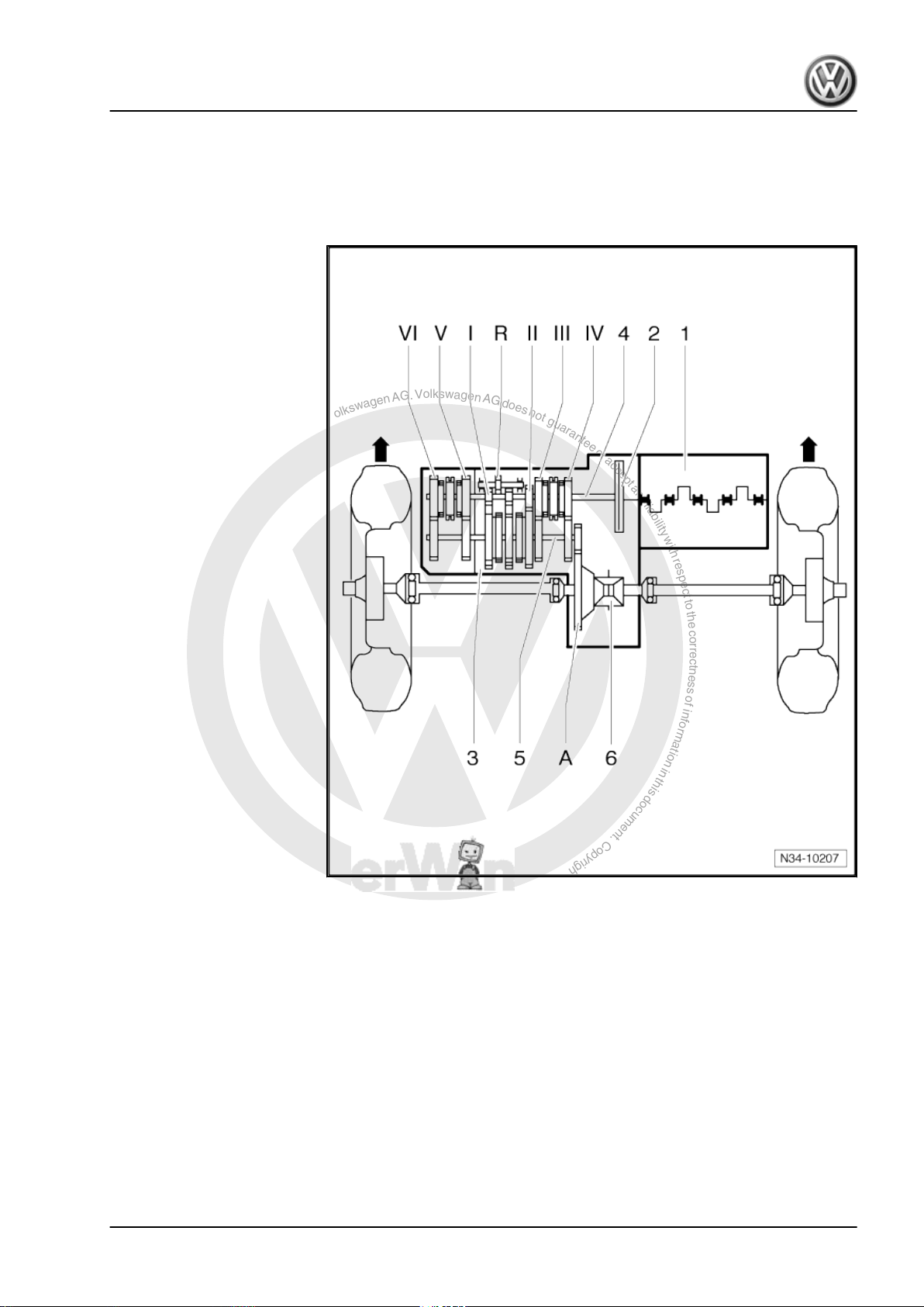
2 Overview - power transmission
Designation
-Arrows- indicate direction of travel.
1 - Engine
2 - Clutch
3 - Manual gearbox
4 - Input shaft
5 - Output shaft
6 - Differential
Gears
-Arrows- indicate direction of travel.
Jetta 2006 ➤ , Golf Variant 2008 ➤
2. Overview - power transmission 3

P
r
o
t
e
c
t
e
d
b
y
c
o
p
y
r
i
g
h
t
.
C
o
p
y
i
n
g
f
o
r
p
r
i
v
a
t
e
o
r
c
o
m
m
e
r
c
i
a
l
p
u
r
p
o
s
e
s
,
i
n
p
a
r
t
o
r
i
n
w
h
o
l
e
,
i
s
n
o
t
p
e
r
m
i
t
t
e
d
u
n
l
e
s
s
a
u
t
h
o
r
i
s
e
d
b
y
V
o
l
k
s
w
a
g
e
n
A
G
.
V
o
l
k
s
w
a
g
e
n
A
G
d
o
e
s
n
o
t
g
u
a
r
a
n
t
e
e
o
r
a
c
c
e
p
t
a
n
y
l
i
a
b
i
l
i
t
y
w
i
t
h
r
e
s
p
e
c
t
t
o
t
h
e
c
o
r
r
e
c
t
n
e
s
s
o
f
i
n
f
o
r
m
a
t
i
o
n
i
n
t
h
i
s
d
o
c
u
m
e
n
t
.
C
o
p
y
r
i
g
h
t
b
y
V
o
l
k
s
w
a
g
e
n
A
G
.
Jetta 2006 ➤ , Golf Variant 2008 ➤
6-speed manual gearbox 0AG - Edition 08.2007
I - 1st gear
II - 2nd gear
III - 3rd gear
IV - 4th gear
V - 5th gear
VI - 6th gear
R - Reverse gear
A - Final drive
4 Rep. Gr.00 - Technical data

P
r
o
t
e
c
t
e
d
b
y
c
o
p
y
r
i
g
h
t
.
C
o
p
y
i
n
g
f
o
r
p
r
i
v
a
t
e
o
r
c
o
m
m
e
r
c
i
a
l
p
u
r
p
o
s
e
s
,
i
n
p
a
r
t
o
r
i
n
w
h
o
l
e
,
i
s
n
o
t
p
e
r
m
i
t
t
e
d
u
n
l
e
s
s
a
u
t
h
o
r
i
s
e
d
b
y
V
o
l
k
s
w
a
g
e
n
A
G
.
V
o
l
k
s
w
a
g
e
n
A
G
d
o
e
s
n
o
t
g
u
a
r
a
n
t
e
e
o
r
a
c
c
e
p
t
a
n
y
l
i
a
b
i
l
i
t
y
w
i
t
h
r
e
s
p
e
c
t
t
o
t
h
e
c
o
r
r
e
c
t
n
e
s
s
o
f
i
n
f
o
r
m
a
t
i
o
n
i
n
t
h
i
s
d
o
c
u
m
e
n
t
.
C
o
p
y
r
i
g
h
t
b
y
V
o
l
k
s
w
a
g
e
n
A
G
.
6-speed manual gearbox 0AG - Edition 08.2007
3 Calculating overall gear ratio “i”
Example:
Jetta 2006 ➤ , Golf Variant 2008 ➤
6th gear Final drive
Drive gear ZG1 = 49 ZA1 = 16
Driven gear ZG2 = 38 ZA2 = 67
i = Z2 : Z1
iG = Gear ratio = ZG2 : ZG1 = 38 : 49 = 0.776
iA = Final drive ratio = ZA2 : ZA1 = 67 : 16 = 4.188
i
total
1) Z1 = No. of teeth on driving gear, Z2 = No. of teeth on driven gear
1)
= Overall ratio = iG x iA = 0.776 x 4.188 = 3.250
3. Calculating overall gear ratio “i” 5
P
r
o
t
e
c
t
e
d
b
y
c
o
p
y
r
i
g
h
t
.
C
o
p
y
i
n
g
f
o
r
p
r
i
v
a
t
e
o
r
c
o
m
m
e
r
c
i
a
l
p
u
r
p
o
s
e
s
,
i
n
p
a
r
t
o
r
i
n
w
h
o
l
e
,
i
s
n
o
t
p
e
r
m
i
t
t
e
d
u
n
l
e
s
s
a
u
t
h
o
r
i
s
e
d
b
y
V
o
l
k
s
w
a
g
e
n
A
G
.
V
o
l
k
s
w
a
g
e
n
A
G
d
o
e
s
n
o
t
g
u
a
r
a
n
t
e
e
o
r
a
c
c
e
p
t
a
n
y
l
i
a
b
i
l
i
t
y
w
i
t
h
r
e
s
p
e
c
t
t
o
t
h
e
c
o
r
r
e
c
t
n
e
s
s
o
f
i
n
f
o
r
m
a
t
i
o
n
i
n
t
h
i
s
d
o
c
u
m
e
n
t
.
C
o
p
y
r
i
g
h
t
b
y
V
o
l
k
s
w
a
g
e
n
A
G
.
Jetta 2006 ➤ , Golf Variant 2008 ➤
6-speed manual gearbox 0AG - Edition 08.2007
4 General repair notes
To ensure perfect and successful gearbox repairs, the greatest
care and cleanliness as well as the use of good and proper tools
is essential. Of course, the basic rules for safety also apply during
repair work.
A number of instructions generally applicable to the various repair
procedures - which were previously repeated a number of times
at various places in the workshop manual are summarised under
the topic “components” ⇒ page 6 . They apply to this workshop
manual.
4.1 Components
4.1.1 Gearbox
♦ When installing the manual gearbox, ensure that the dowel
sleeves between the engine and gearbox are correctly seated.
♦ When installing mounting brackets or waxed components,
clean the contact surfaces. Contact surfaces must be free of
wax and grease.
♦ Allocate bolts and other components using ⇒ Electronic parts
catalogue “ETKA” .
♦ Following installation, check gear oil level
♦ Capacities ⇒ page 1
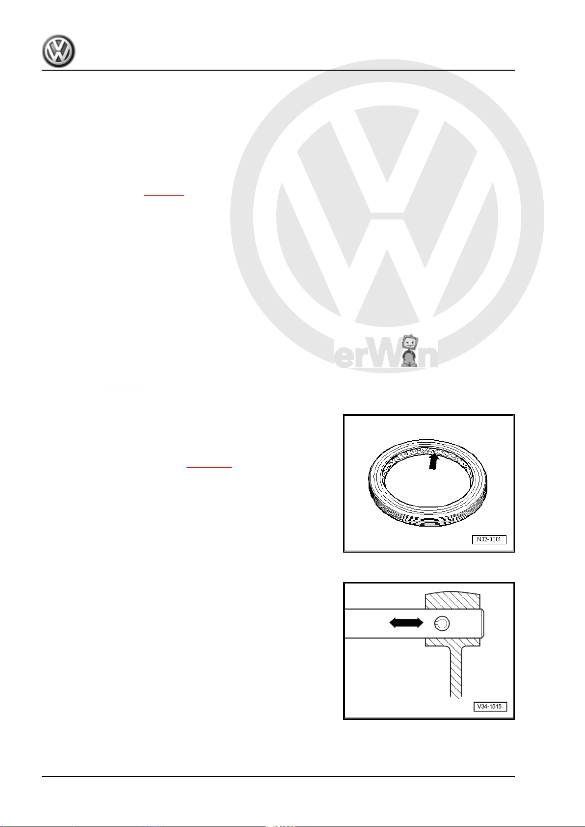
4.1.2 Seals and sealing rings
♦ Before installing oil seal, half-fill space between sealing lips
with sealing grease -G 052 128 A1- -arrow-.
♦ The open side of the oil seal faces the side with fluid filling.
♦ After installing, check oil level ⇒ page 70 .
Lightly oil O-rings before installing; this prevents the rings being
crushed when inserted.
♦ Thoroughly clean parting surfaces and apply sealant -AMV
188 200 03- .
♦ Apply sealant uniformly but not too thick.
4.1.3 Locking devices
♦ Renew retaining rings.
♦ Do not overstretch retaining rings.
♦ Retaining rings must locate properly in grooves.
♦ Renew spring pins. Installation position: slot longitudinal to line
of force.
6 Rep. Gr.00 - Technical data
P
r
o
t
e
c
t
e
d
b
y
c
o
p
y
r
i
g
h
t
.
C
o
p
y
i
n
g
f
o
r
p
r
i
v
a
t
e
o
r
c
o
m
m
e
r
c
i
a
l
p
u
r
p
o
s
e
s
,
i
n
p
a
r
t
o
r
i
n
w
h
o
l
e
,
i
s
n
o
t
p
e
r
m
i
t
t
e
d
u
n
l
e
s
s
a
u
t
h
o
r
i
s
e
d
b
y
V
o
l
k
s
w
a
g
e
n
A
G
.
V
o
l
k
s
w
a
g
e
n
A
G
d
o
e
s
n
o
t
g
u
a
r
a
n
t
e
e
o
r
a
c
c
e
p
t
a
n
y
l
i
a
b
i
l
i
t
y
w
i
t
h
r
e
s
p
e
c
t
t
o
t
h
e
c
o
r
r
e
c
t
n
e
s
s
o
f
i
n
f
o
r
m
a
t
i
o
n
i
n
t
h
i
s
d
o
c
u
m
e
n
t
.
C
o
p
y
r
i
g
h
t
b
y
V
o
l
k
s
w
a
g
e
n
A
G
.
6-speed manual gearbox 0AG - Edition 08.2007
4.1.4 Nuts and bolts
♦ Loosen and tighten securing bolts and nuts for covers and
housings diagonally.
♦ Do not cant especially delicate parts, such as clutch pressure
plates. Loosen and tighten bolts and nuts in stages in a diag‐
onal sequence.
♦ Torque settings are specified for unoiled bolts and nuts.
♦ Always renew self-locking bolts and nuts.
♦ Ensure with threaded connections that contact surfaces as
well as nuts and bolts are rewaxed only after assembly, if nec‐
essary.
♦ Use a thread chaser to clear residual locking fluid from all
threaded holes into which self-locking bolts are to be screwed.
Otherwise there is a danger of bolts shearing when subse‐
quently being removed.
4.1.5 Bearings
♦ Install new tapered roller bearings as supplied and do not lu‐
bricate additionally.
♦ Install needle bearings with lettered side (thicker metal) to‐
wards fitting tool.
♦ Tapered roller bearings fitted to one shaft must be renewed as
a set. Use same make of bearings.
♦ Heat inner races to about 100° C with the inductive heater -
VAS 6414- before installing.
♦ Do not interchange outer or inner races of bearings of the
same size. The bearings are matched in pairs.
4.1.6 Shims
♦ Measure shims at several points with a micrometer. The var‐
ious thicknesses make it possible to achieve the exact shim
thickness required.
♦ Check for burrs and damage.
♦ Install only flawless shims.
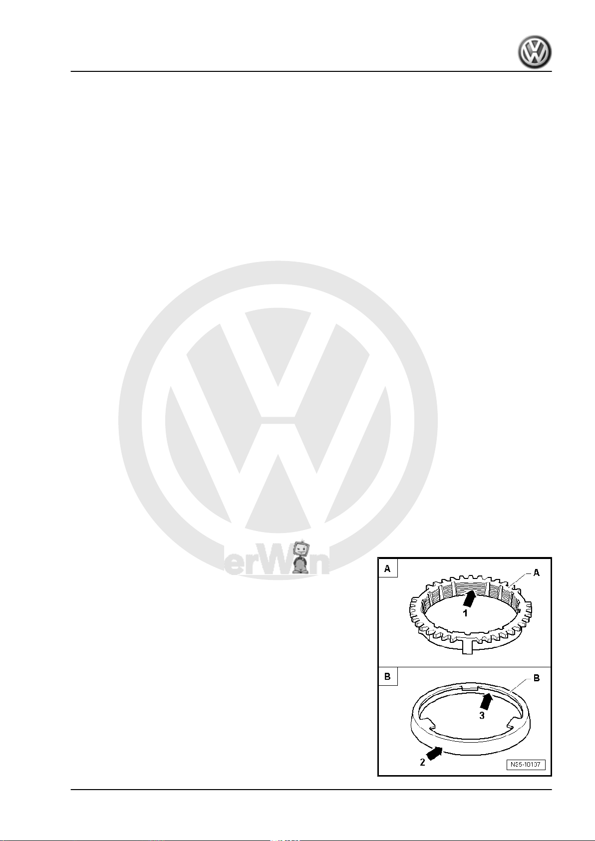
4.1.7 Synchro-rings
♦ Do not interchange. When reusing synchro-rings, always fit to
the same gear.
♦ Check for wear and renew if necessary.
♦ Check grooves -arrow 1- of synchro-ring -A- and inner ring for
flat spots (worn grooves).
♦ If synchro-rings are coated, coating must not be damaged.
♦ If an intermediate ring -B- is installed, check the outer friction
surface -arrow 2- and inner friction surface -arrow 3- of this
intermediate ring for “scoring”, “signs of abnormal wear” and
“blue discolouration (due to overheating)”.
♦ Check cone of synchromeshed gear for “scoring” and “signs
of abnormal wear”.
♦ Moisten synchromesh mechanism with gear oil before instal‐
ling.
Jetta 2006 ➤ , Golf Variant 2008 ➤
4. General repair notes 7

P
r
o
t
e
c
t
e
d
b
y
c
o
p
y
r
i
g
h
t
.
C
o
p
y
i
n
g
f
o
r
p
r
i
v
a
t
e
o
r
c
o
m
m
e
r
c
i
a
l
p
u
r
p
o
s
e
s
,
i
n
p
a
r
t
o
r
i
n
w
h
o
l
e
,
i
s
n
o
t
p
e
r
m
i
t
t
e
d
u
n
l
e
s
s
a
u
t
h
o
r
i
s
e
d
b
y
V
o
l
k
s
w
a
g
e
n
A
G
.
V
o
l
k
s
w
a
g
e
n
A
G
d
o
e
s
n
o
t
g
u
a
r
a
n
t
e
e
o
r
a
c
c
e
p
t
a
n
y
l
i
a
b
i
l
i
t
y
w
i
t
h
r
e
s
p
e
c
t
t
o
t
h
e
c
o
r
r
e
c
t
n
e
s
s
o
f
i
n
f
o
r
m
a
t
i
o
n
i
n
t
h
i
s
d
o
c
u
m
e
n
t
.
C
o
p
y
r
i
g
h
t
b
y
V
o
l
k
s
w
a
g
e
n
A
G
.
Jetta 2006 ➤ , Golf Variant 2008 ➤
6-speed manual gearbox 0AG - Edition 08.2007
4.1.8 Gear wheels
♦ Before installing, clean and heat with the inductive heater -
VAS 6414- to maximum 100° C.
4.1.9 Synchromeshed gears
♦ After assembly, check synchromeshed gears for slight play, or
for freedom of movement.
4.1.10 Clutch
♦ Ensure that the pressure plate does not cant: loosen and tight‐
en bolts diagonally and in several gradual stages.
♦ If the clutch has burnt out, thoroughly clean the bell housing
as well as the friction surface of flywheel with a cloth to reduce
the smell of burnt linings.
8 Rep. Gr.00 - Technical data

P
r
o
t
e
c
t
e
d
b
y
c
o
p
y
r
i
g
h
t
.
C
o
p
y
i
n
g
f
o
r
p
r
i
v
a
t
e
o
r
c
o
m
m
e
r
c
i
a
l
p
u
r
p
o
s
e
s
,
i
n
p
a
r
t
o
r
i
n
w
h
o
l
e
,
i
s
n
o
t
p
e
r
m
i
t
t
e
d
u
n
l
e
s
s
a
u
t
h
o
r
i
s
e
d
b
y
V
o
l
k
s
w
a
g
e
n
A
G
.
V
o
l
k
s
w
a
g
e
n
A
G
d
o
e
s
n
o
t
g
u
a
r
a
n
t
e
e
o
r
a
c
c
e
p
t
a
n
y
l
i
a
b
i
l
i
t
y
w
i
t
h
r
e
s
p
e
c
t
t
o
t
h
e
c
o
r
r
e
c
t
n
e
s
s
o
f
i
n
f
o
r
m
a
t
i
o
n
i
n
t
h
i
s
d
o
c
u
m
e
n
t
.
C
o
p
y
r
i
g
h
t
b
y
V
o
l
k
s
w
a
g
e
n
A
G
.
6-speed manual gearbox 0AG - Edition 08.2007
30 – Clutch
1 Fault finding, power transmission
– Refer to ⇒ Fault finding, power transmission; Rep. Gr. 30 ;
Complaints about clutch and clutch mechanism and ⇒ Fault
finding, power transmission; Rep. Gr. 34 ; Complaints about
selector mechanism
Jetta 2006 ➤ , Golf Variant 2008 ➤
1. Fault finding, power transmission 9
P
r
o
t
e
c
t
e
d
b
y
c
o
p
y
r
i
g
h
t
.
C
o
p
y
i
n
g
f
o
r
p
r
i
v
a
t
e
o
r
c
o
m
m
e
r
c
i
a
l
p
u
r
p
o
s
e
s
,
i
n
p
a
r
t
o
r
i
n
w
h
o
l
e
,
i
s
n
o
t
p
e
r
m
i
t
t
e
d
u
n
l
e
s
s
a
u
t
h
o
r
i
s
e
d
b
y
V
o
l
k
s
w
a
g
e
n
A
G
.
V
o
l
k
s
w
a
g
e
n
A
G
d
o
e
s
n
o
t
g
u
a
r
a
n
t
e
e
o
r
a
c
c
e
p
t
a
n
y
l
i
a
b
i
l
i
t
y
w
i
t
h
r
e
s
p
e
c
t
t
o
t
h
e
c
o
r
r
e
c
t
n
e
s
s
o
f
i
n
f
o
r
m
a
t
i
o
n
i
n
t
h
i
s
d
o
c
u
m
e
n
t
.
C
o
p
y
r
i
g
h
t
b
y
V
o
l
k
s
w
a
g
e
n
A
G
.
Jetta 2006 ➤ , Golf Variant 2008 ➤
6-speed manual gearbox 0AG - Edition 08.2007
2 Repairing clutch mechanism
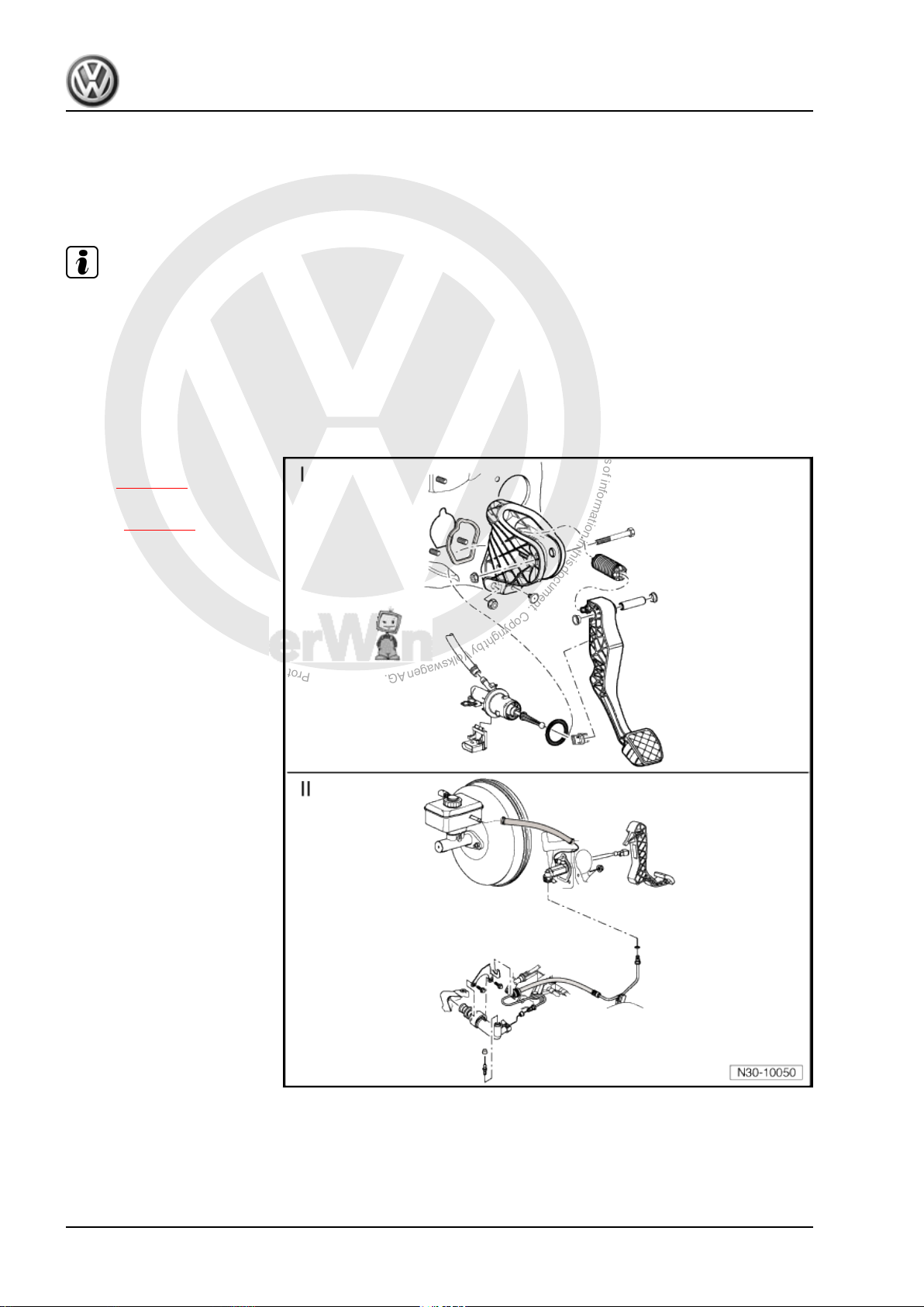
2.1 Overview
Note
♦
♦
♦
♦
I - Assembly overview - pedal
cluster ⇒ page 11 .
II - Assembly overview - hy‐
draulics ⇒ page 24 .
Before disconnecting battery, obtain code for radio units having anti-theft coding.
With ignition switched off, disconnect battery ⇒ Electrical system; Rep. Gr. 27 ; Disconnecting and con‐
necting battery .
When reconnecting battery, refer to ⇒ Electrical system; Rep. Gr. 27 ; Disconnecting and connecting
battery .
Lubricate all bearings and contact surfaces with grease -G 000 450 02- .
10 Rep. Gr.30 - Clutch
P
r
o
t
e
c
t
e
d
b
y
c
o
p
y
r
i
g
h
t
.
C
o
p
y
i
n
g
f
o
r
p
r
i
v
a
t
e
o
r
c
o
m
m
e
r
c
i
a
l
p
u
r
p
o
s
e
s
,
i
n
p
a
r
t
o
r
i
n
w
h
o
l
e
,
i
s
n
o
t
p
e
r
m
i
t
t
e
d
u
n
l
e
s
s
a
u
t
h
o
r
i
s
e
d
b
y
V
o
l
k
s
w
a
g
e
n
A
G
.
V
o
l
k
s
w
a
g
e
n
A
G
d
o
e
s
n
o
t
g
u
a
r
a
n
t
e
e
o
r
a
c
c
e
p
t
a
n
y
l
i
a
b
i
l
i
t
y
w
i
t
h
r
e
s
p
e
c
t
t
o
t
h
e
c
o
r
r
e
c
t
n
e
s
s
o
f
i
n
f
o
r
m
a
t
i
o
n
i
n
t
h
i
s
d
o
c
u
m
e
n
t
.
C
o
p
y
r
i
g
h
t
b
y
V
o
l
k
s
w
a
g
e
n
A
G
.
Jetta 2006 ➤ , Golf Variant 2008 ➤
6-speed manual gearbox 0AG - Edition 08.2007
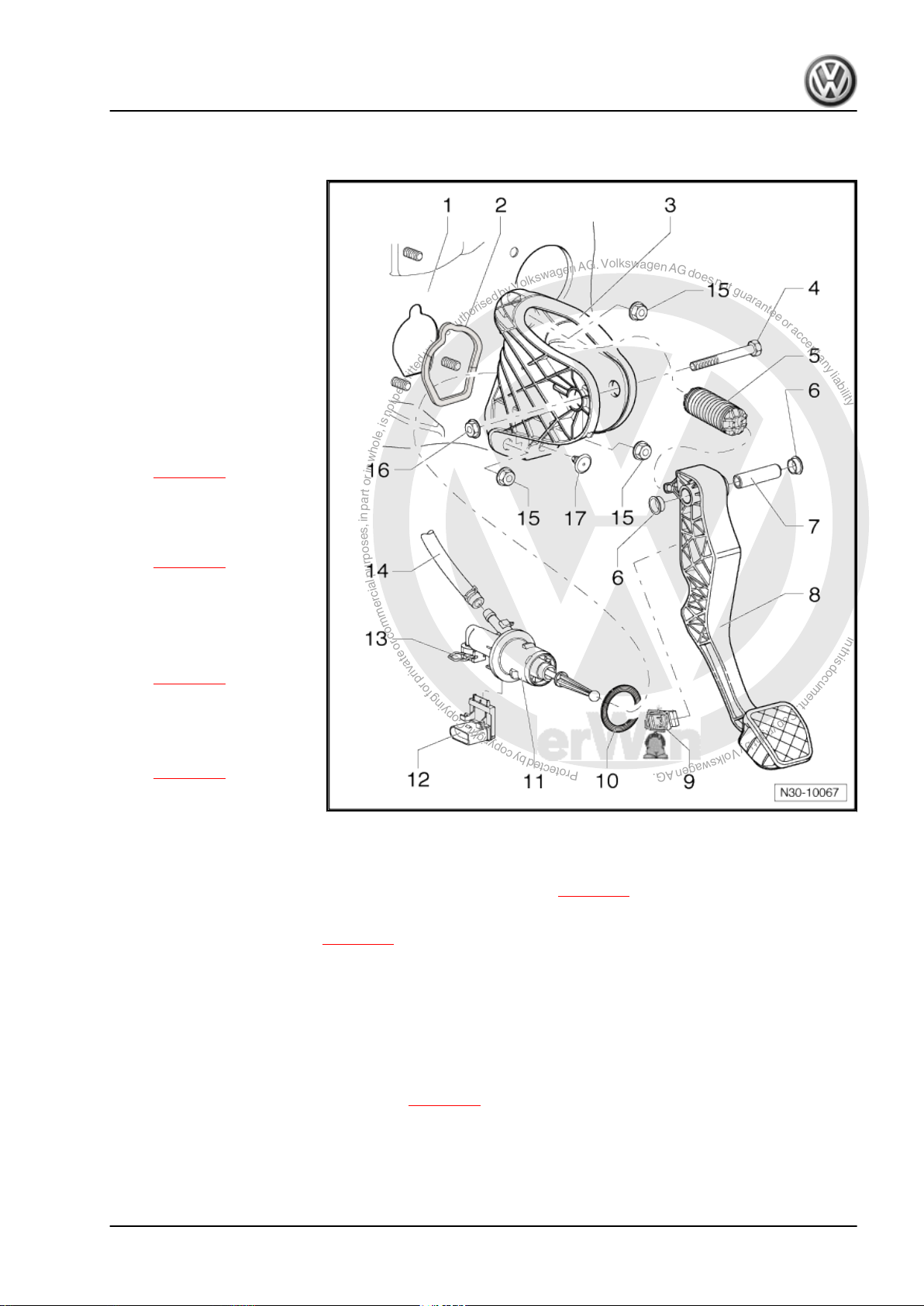
2.2 Assembly overview - pedal cluster
1 - Bulkhead
❑ With support for mount‐
ing bracket
2 - Seal
❑ Always renew
❑ Between mounting
bracket and bulkhead
❑ Self-adhesive
❑ Bond to mounting
bracket
3 - Mounting bracket
❑ For mounting clutch
pedal
❑ Removing and installing
⇒ page 16
4 - Bolt
5 - Over-centre spring
❑ Removing and installing
⇒ page 12
6 - Bearing bush
7 - Pivot pin
8 - Clutch pedal
❑ Removing and installing
⇒ page 14
9 - Retainer
❑ To remove and install,
separate master cylin‐
der from clutch pedal.
⇒ page 14
10 - Seal
❑ Always renew
❑ Between master cylinder and mounting bracket
11 - Master cylinder
❑ Removing and installing after removal of mounting bracket ⇒ page 19
12 - Clutch position sender -G476-
❑ Removing and installing ⇒ page 21
❑ Can be checked in “guided fault finding” of vehicle diagnosis, testing and information system -VAS 5051- .
❑ The clutch position sender -G476- is identified as clutch pedal switch -F36- in “guided fault finding”.
13 - Clip
❑ Pull out clip to stop to remove and install pipe/hose line or plastic line
14 - Supply hose
❑ Rubber
❑ From 12.05, plastic in some vehicles ⇒ page 25
15 - Self-locking hexagon nut, 25 Nm
❑ Qty. 3
❑ For mounting bracket on bulkhead
❑ Always renew
2. Repairing clutch mechanism 11
P
r
o
t
e
c
t
e
d
b
y
c
o
p
y
r
i
g
h
t
.
C
o
p
y
i
n
g
f
o
r
p
r
i
v
a
t
e
o
r
c
o
m
m
e
r
c
i
a
l
p
u
r
p
o
s
e
s
,
i
n
p
a
r
t
o
r
i
n
w
h
o
l
e
,
i
s
n
o
t
p
e
r
m
i
t
t
e
d
u
n
l
e
s
s
a
u
t
h
o
r
i
s
e
d
b
y
V
o
l
k
s
w
a
g
e
n
A
G
.
V
o
l
k
s
w
a
g
e
n
A
G
d
o
e
s
n
o
t
g
u
a
r
a
n
t
e
e
o
r
a
c
c
e
p
t
a
n
y
l
i
a
b
i
l
i
t
y
w
i
t
h
r
e
s
p
e
c
t
t
o
t
h
e
c
o
r
r
e
c
t
n
e
s
s
o
f
i
n
f
o
r
m
a
t
i
o
n
i
n
t
h
i
s
d
o
c
u
m
e
n
t
.
C
o
p
y
r
i
g
h
t
b
y
V
o
l
k
s
w
a
g
e
n
A
G
.
Jetta 2006 ➤ , Golf Variant 2008 ➤
6-speed manual gearbox 0AG - Edition 08.2007
16 - Hexagon nut, 25 Nm
❑ Always renew
17 - Stop
❑ For clutch pedal
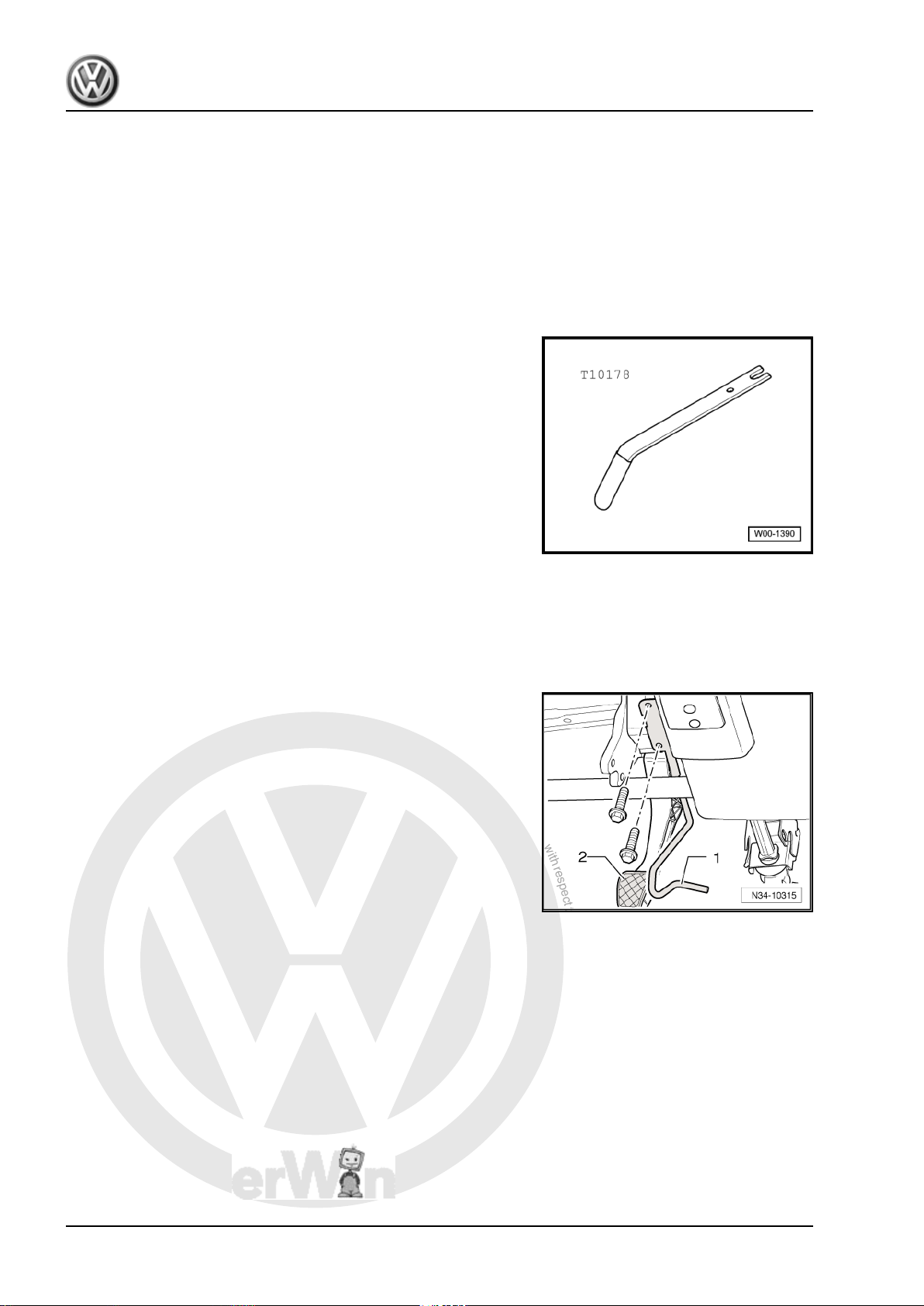
2.3 Removing and installing over-centre spring
Special tools and workshop equipment required
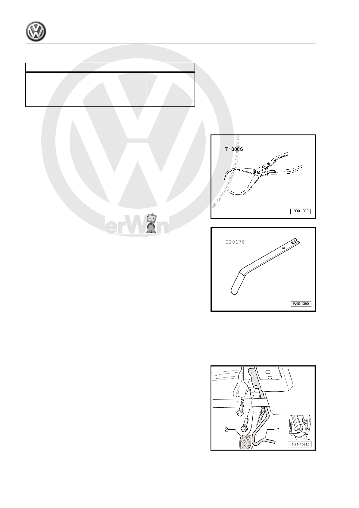
♦ Release tool -T10178-
2.3.1 Removing
– Push driver seat as far back as possible and put steering wheel
in highest position.
– Remove trim and cover below trim on drive side ⇒ General
body repairs, interior; Rep. Gr. 68 .
– Now unbolt crash bar -1- from in front of clutch pedal -2-.
12 Rep. Gr.30 - Clutch
P
r
o
t
e
c
t
e
d
b
y
c
o
p
y
r
i
g
h
t
.
C
o
p
y
i
n
g
f
o
r
p
r
i
v
a
t
e
o
r
c
o
m
m
e
r
c
i
a
l
p
u
r
p
o
s
e
s
,
i
n
p
a
r
t
o
r
i
n
w
h
o
l
e
,
i
s
n
o
t
p
e
r
m
i
t
t
e
d
u
n
l
e
s
s
a
u
t
h
o
r
i
s
e
d
b
y
V
o
l
k
s
w
a
g
e
n
A
G
.
V
o
l
k
s
w
a
g
e
n
A
G
d
o
e
s
n
o
t
g
u
a
r
a
n
t
e
e
o
r
a
c
c
e
p
t
a
n
y
l
i
a
b
i
l
i
t
y
w
i
t
h
r
e
s
p
e
c
t
t
o
t
h
e
c
o
r
r
e
c
t
n
e
s
s
o
f
i
n
f
o
r
m
a
t
i
o
n
i
n
t
h
i
s
d
o
c
u
m
e
n
t
.
C
o
p
y
r
i
g
h
t
b
y
V
o
l
k
s
w
a
g
e
n
A
G
.
6-speed manual gearbox 0AG - Edition 08.2007
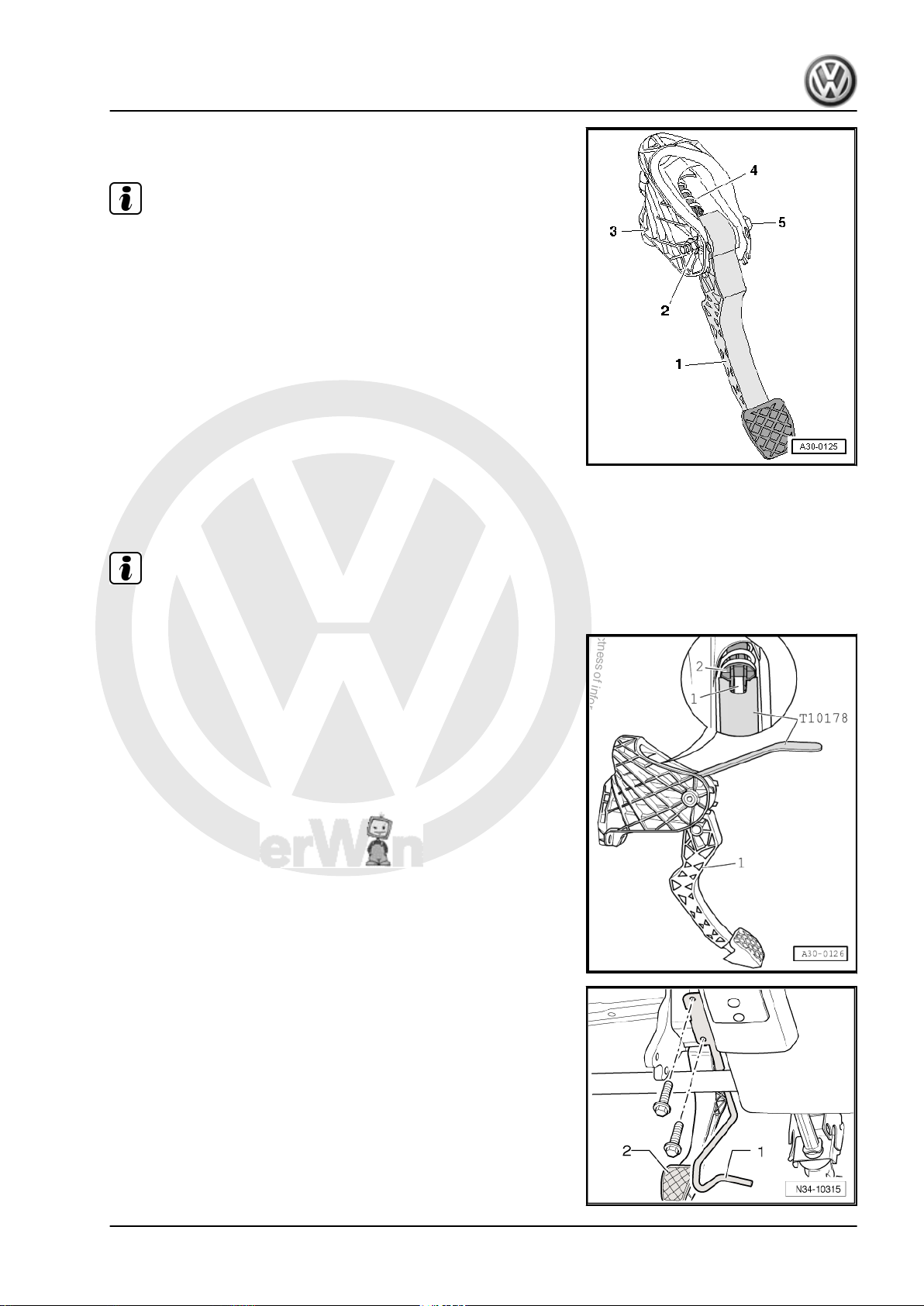
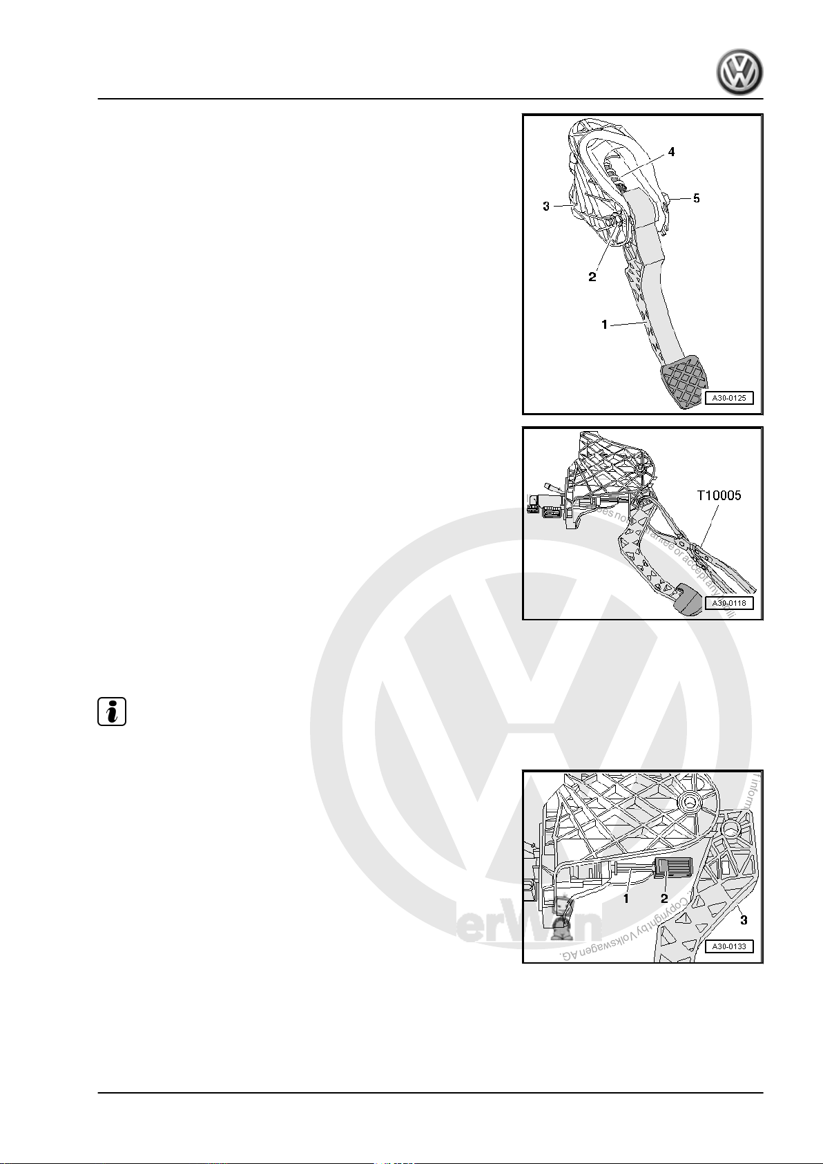
– Unbolt clutch pedal -1- from mounting bracket -3- by removing
nut -2- and pulling out bolt -5-.
Note
The clutch pedal remains hooked to operating rod of master cyl‐
inder.
– Swing clutch pedal down slightly and remove over-centre
spring -4- from mounting bracket.
2.3.2 Installing
Install in the reverse order of removal, observing the following:
Note
Renew self-locking nuts.
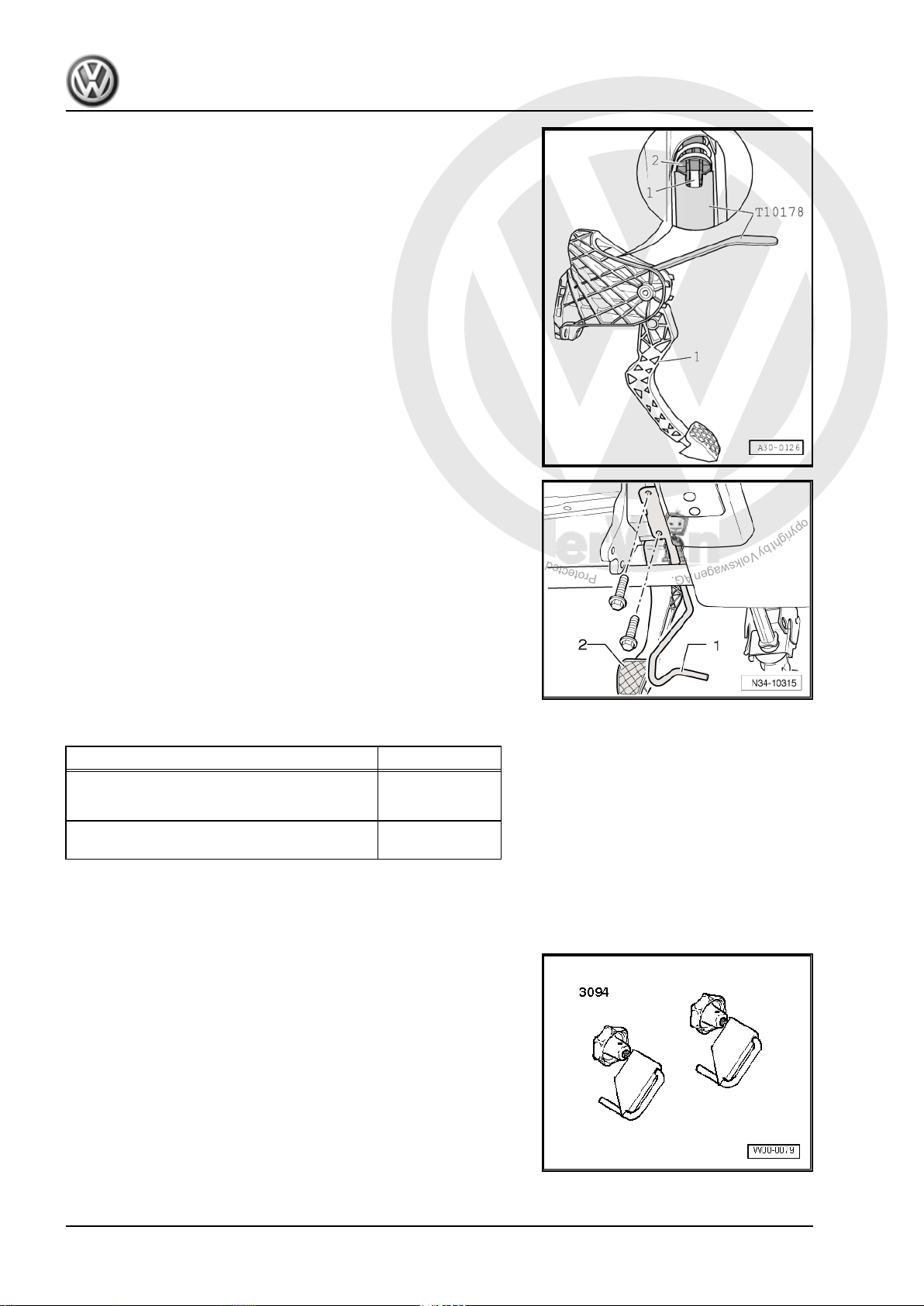
– Insert over-centre spring in mounting bracket from above while
holding end of spring with release tool -T10178- in installation
position.
– Insert tip of clutch pedal in bearing recess of over-centre
spring.
– Depress clutch pedal slightly, push bolt through and tighten
self-locking nut.
Jetta 2006 ➤ , Golf Variant 2008 ➤
– Now bolt on crash bar -1- in front of clutch pedal -2-.
– Install trim and cover below trim on drive side ⇒ General body
repairs, interior; Rep. Gr. 68 .
2. Repairing clutch mechanism 13
P
r
o
t
e
c
t
e
d
b
y
c
o
p
y
r
i
g
h
t
.
C
o
p
y
i
n
g
f
o
r
p
r
i
v
a
t
e
o
r
c
o
m
m
e
r
c
i
a
l
p
u
r
p
o
s
e
s
,
i
n
p
a
r
t
o
r
i
n
w
h
o
l
e
,
i
s
n
o
t
p
e
r
m
i
t
t
e
d
u
n
l
e
s
s
a
u
t
h
o
r
i
s
e
d
b
y
V
o
l
k
s
w
a
g
e
n
A
G
.
V
o
l
k
s
w
a
g
e
n
A
G
d
o
e
s
n
o
t
g
u
a
r
a
n
t
e
e
o
r
a
c
c
e
p
t
a
n
y
l
i
a
b
i
l
i
t
y
w
i
t
h
r
e
s
p
e
c
t
t
o
t
h
e
c
o
r
r
e
c
t
n
e
s
s
o
f
i
n
f
o
r
m
a
t
i
o
n
i
n
t
h
i
s
d
o
c
u
m
e
n
t
.
C
o
p
y
r
i
g
h
t
b
y
V
o
l
k
s
w
a
g
e
n
A
G
.
Jetta 2006 ➤ , Golf Variant 2008 ➤
6-speed manual gearbox 0AG - Edition 08.2007
2.3.3 Torque settings
Component Nm
Clutch pedal to mounting bracket
♦ Renew self-locking nuts
Crash bar to steering column mounting
bracket
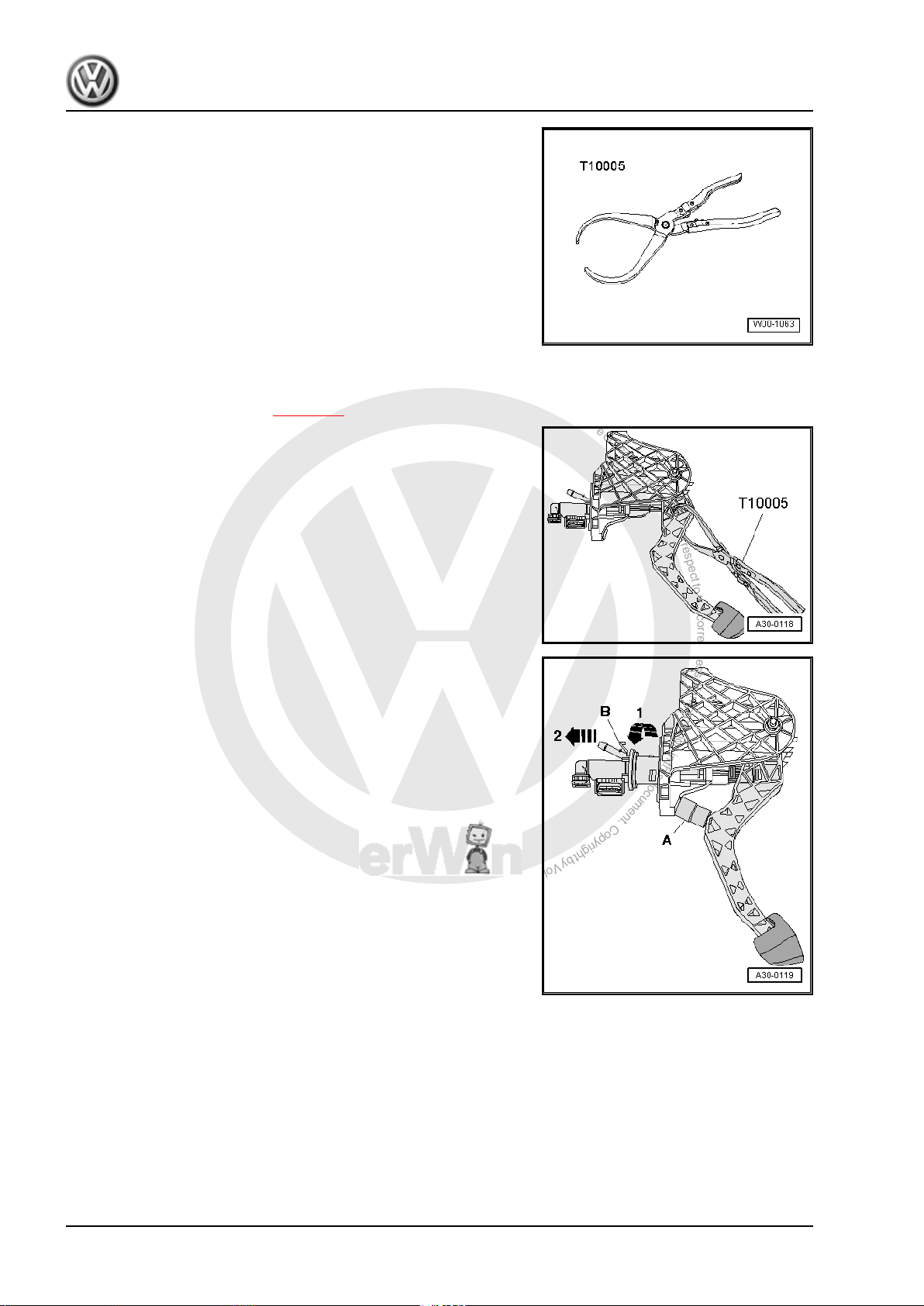
2.4 Removing and installing clutch pedal
Special tools and workshop equipment required
♦ Pliers -T10005-
♦ Release tool -T10178-
25
10
2.4.1 Removing
– Push driver seat as far back as possible and put steering wheel
in highest position.
– Remove trim and cover below trim on drive side ⇒ General
body repairs, interior; Rep. Gr. 68 .
– Now unbolt crash bar -1- from in front of clutch pedal -2-.
14 Rep. Gr.30 - Clutch
P
r
o
t
e
c
t
e
d
b
y
c
o
p
y
r
i
g
h
t
.
C
o
p
y
i
n
g
f
o
r
p
r
i
v
a
t
e
o
r
c
o
m
m
e
r
c
i
a
l
p
u
r
p
o
s
e
s
,
i
n
p
a
r
t
o
r
i
n
w
h
o
l
e
,
i
s
n
o
t
p
e
r
m
i
t
t
e
d
u
n
l
e
s
s
a
u
t
h
o
r
i
s
e
d
b
y
V
o
l
k
s
w
a
g
e
n
A
G
.
V
o
l
k
s
w
a
g
e
n
A
G
d
o
e
s
n
o
t
g
u
a
r
a
n
t
e
e
o
r
a
c
c
e
p
t
a
n
y
l
i
a
b
i
l
i
t
y
w
i
t
h
r
e
s
p
e
c
t
t
o
t
h
e
c
o
r
r
e
c
t
n
e
s
s
o
f
i
n
f
o
r
m
a
t
i
o
n
i
n
t
h
i
s
d
o
c
u
m
e
n
t
.
C
o
p
y
r
i
g
h
t
b
y
V
o
l
k
s
w
a
g
e
n
A
G
.
6-speed manual gearbox 0AG - Edition 08.2007
– Unbolt clutch pedal -1- from mounting bracket -3- by removing
nut -2- and pulling out bolt -5-.
– Swing clutch pedal forward slightly and remove over-centre
spring -4- from mounting bracket.
– Release clutch pedal from master cylinder with pliers -
T10005- .
– Remove clutch pedal.
Jetta 2006 ➤ , Golf Variant 2008 ➤
2.4.2 Installing
Install in the reverse order of removal, observing the following:
Note
Renew self-locking nuts.
– Attach retainer -2- to master cylinder operating rod -1-.
– Press retainer into notch in clutch pedal -3- until it can be heard
to engage.
2. Repairing clutch mechanism 15
P
r
o
t
e
c
t
e
d
b
y
c
o
p
y
r
i
g
h
t
.
C
o
p
y
i
n
g
f
o
r
p
r
i
v
a
t
e
o
r
c
o
m
m
e
r
c
i
a
l
p
u
r
p
o
s
e
s
,
i
n
p
a
r
t
o
r
i
n
w
h
o
l
e
,
i
s
n
o
t
p
e
r
m
i
t
t
e
d
u
n
l
e
s
s
a
u
t
h
o
r
i
s
e
d
b
y
V
o
l
k
s
w
a
g
e
n
A
G
.
V
o
l
k
s
w
a
g
e
n
A
G
d
o
e
s
n
o
t
g
u
a
r
a
n
t
e
e
o
r
a
c
c
e
p
t
a
n
y
l
i
a
b
i
l
i
t
y
w
i
t
h
r
e
s
p
e
c
t
t
o
t
h
e
c
o
r
r
e
c
t
n
e
s
s
o
f
i
n
f
o
r
m
a
t
i
o
n
i
n
t
h
i
s
d
o
c
u
m
e
n
t
.
C
o
p
y
r
i
g
h
t
b
y
V
o
l
k
s
w
a
g
e
n
A
G
.
Jetta 2006 ➤ , Golf Variant 2008 ➤
6-speed manual gearbox 0AG - Edition 08.2007
– Insert over-centre spring in mounting bracket from above while
holding end of spring with release tool -T10178- in installation
position.
– Insert tip of clutch pedal in bearing recess of over-centre
spring.
– Depress clutch pedal slightly, push bolt through and tighten
self-locking nut.
– Now bolt on crash bar -1- in front of clutch pedal -2-.
– Install trim and cover below trim on drive side ⇒ General body
repairs, interior; Rep. Gr. 68 .
2.4.3 Torque settings
Component Nm
Clutch pedal to mounting bracket
25
♦ Renew self-locking nuts
Crash bar to steering column mounting
10
bracket
2.5 Removing and installing mounting bracket
Special tools and workshop equipment required
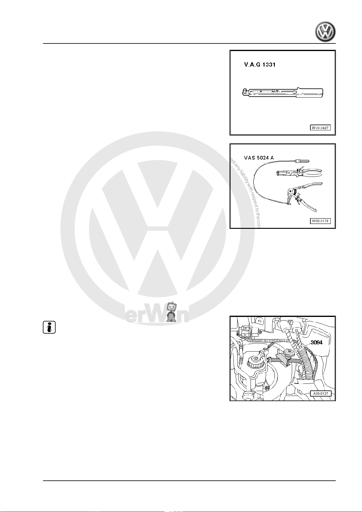
♦ Hose clamps to 25 mm Ø -3094-
16 Rep. Gr.30 - Clutch
P
r
o
t
e
c
t
e
d
b
y
c
o
p
y
r
i
g
h
t
.
C
o
p
y
i
n
g
f
o
r
p
r
i
v
a
t
e
o
r
c
o
m
m
e
r
c
i
a
l
p
u
r
p
o
s
e
s
,
i
n
p
a
r
t
o
r
i
n
w
h
o
l
e
,
i
s
n
o
t
p
e
r
m
i
t
t
e
d
u
n
l
e
s
s
a
u
t
h
o
r
i
s
e
d
b
y
V
o
l
k
s
w
a
g
e
n
A
G
.
V
o
l
k
s
w
a
g
e
n
A
G
d
o
e
s
n
o
t
g
u
a
r
a
n
t
e
e
o
r
a
c
c
e
p
t
a
n
y
l
i
a
b
i
l
i
t
y
w
i
t
h
r
e
s
p
e
c
t
t
o
t
h
e
c
o
r
r
e
c
t
n
e
s
s
o
f
i
n
f
o
r
m
a
t
i
o
n
i
n
t
h
i
s
d
o
c
u
m
e
n
t
.
C
o
p
y
r
i
g
h
t
b
y
V
o
l
k
s
w
a
g
e
n
A
G
.
6-speed manual gearbox 0AG - Edition 08.2007
♦ Torque wrench -V.A.G 1331-
♦ Spring-type clip pliers -VAS 5024 A-
2.5.1 Removing
– First check whether a coded radio is fitted. If so, obtain anti-
– With ignition switched off, disconnect battery ⇒ Electrical sys‐
– Remove complete air filter housing if it is near battery ⇒ Rep.
theft code.
tem; Rep. Gr. 27 ; Disconnecting and connecting battery .
Gr. 24 ; Repairing injection system .
– Remove battery and battery tray ⇒ Electrical system; Rep.
Gr. 27 ; Removing and installing battery .
Note
Jetta 2006 ➤ , Golf Variant 2008 ➤
♦
During the following work, ensure that no brake fluid lands on
longitudinal member or gearbox. If this does happen, clean the
affected areas thoroughly.
♦
Place a lint-free cloth under the master cylinder.
– Clamp off supply hose to master cylinder using hose clamp
-3094- .
2. Repairing clutch mechanism 17
P
r
o
t
e
c
t
e
d
b
y
c
o
p
y
r
i
g
h
t
.
C
o
p
y
i
n
g
f
o
r
p
r
i
v
a
t
e
o
r
c
o
m
m
e
r
c
i
a
l
p
u
r
p
o
s
e
s
,
i
n
p
a
r
t
o
r
i
n
w
h
o
l
e
,
i
s
n
o
t
p
e
r
m
i
t
t
e
d
u
n
l
e
s
s
a
u
t
h
o
r
i
s
e
d
b
y
V
o
l
k
s
w
a
g
e
n
A
G
.
V
o
l
k
s
w
a
g
e
n
A
G
d
o
e
s
n
o
t
g
u
a
r
a
n
t
e
e
o
r
a
c
c
e
p
t
a
n
y
l
i
a
b
i
l
i
t
y
w
i
t
h
r
e
s
p
e
c
t
t
o
t
h
e
c
o
r
r
e
c
t
n
e
s
s
o
f
i
n
f
o
r
m
a
t
i
o
n
i
n
t
h
i
s
d
o
c
u
m
e
n
t
.
C
o
p
y
r
i
g
h
t
b
y
V
o
l
k
s
w
a
g
e
n
A
G
.
Jetta 2006 ➤ , Golf Variant 2008 ➤
6-speed manual gearbox 0AG - Edition 08.2007
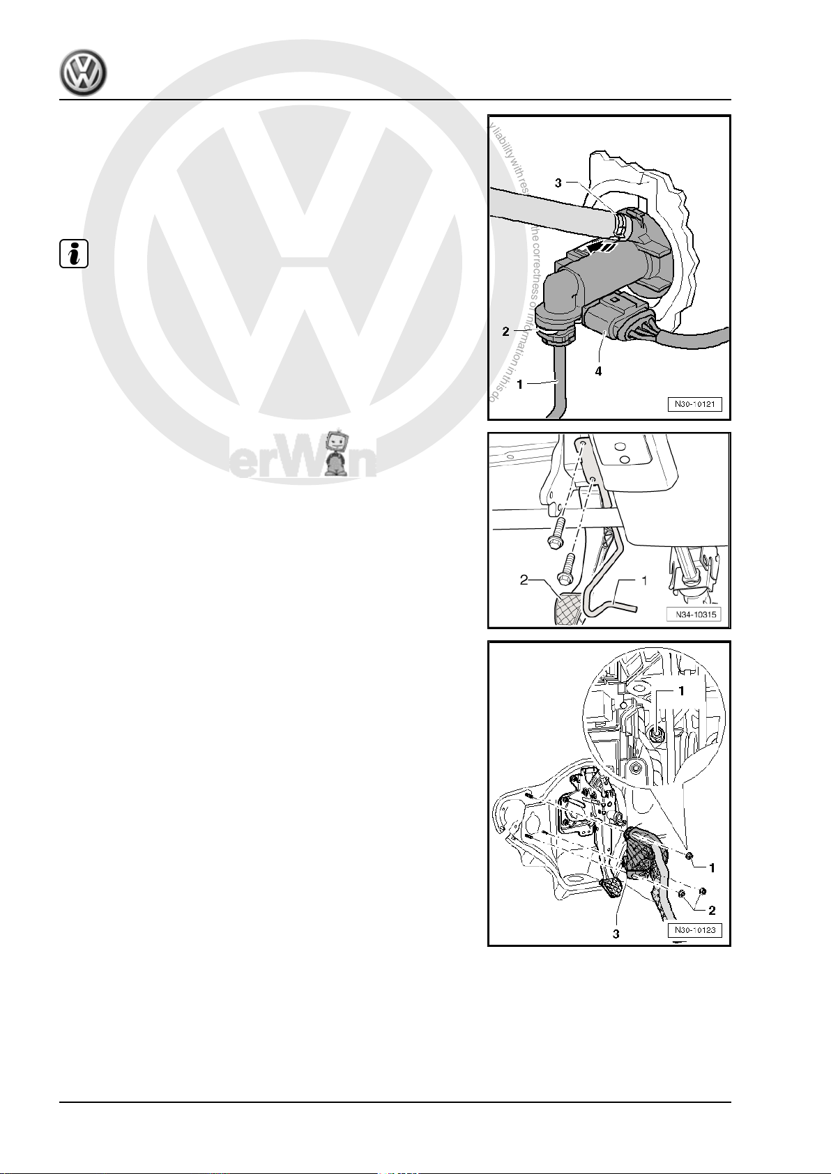
– Loosen spring-type clip -3- with spring-type clip pliers -VAS
5024- and pull supply hose off master cylinder.
– Release securing clip -2- using screwdriver and pull pipe/hose
line or plastic line -1- off master cylinder.
– Unclip clutch position sender -G476- from master cylinder
When performing work in the footwell, put cloths on the carpet to
protect it from possible brake fluid spills.
– Remove trim and cover below trim on drive side ⇒ General
– Now unbolt crash bar -1- from in front of clutch pedal -2-.
-arrow- and remove with electrical connector attached -4-.
Note
body repairs, interior; Rep. Gr. 68 .
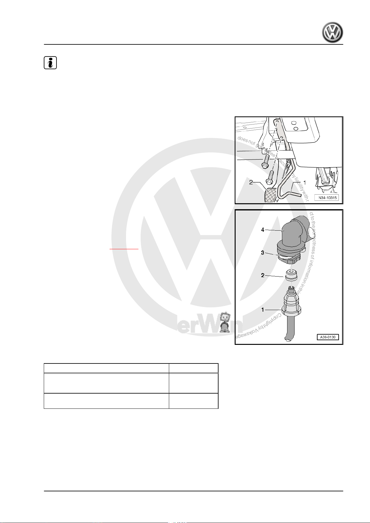
– Remove securing nuts -1- and -2-.
The upper securing nut -1- is accessible between the relay carrier
and the steering column trim.
– Remove mounting bracket -3-.
2.5.2 Installing
Install in the reverse order of removal, observing the following:
18 Rep. Gr.30 - Clutch
P
r
o
t
e
c
t
e
d
b
y
c
o
p
y
r
i
g
h
t
.
C
o
p
y
i
n
g
f
o
r
p
r
i
v
a
t
e
o
r
c
o
m
m
e
r
c
i
a
l
p
u
r
p
o
s
e
s
,
i
n
p
a
r
t
o
r
i
n
w
h
o
l
e
,
i
s
n
o
t
p
e
r
m
i
t
t
e
d
u
n
l
e
s
s
a
u
t
h
o
r
i
s
e
d
b
y
V
o
l
k
s
w
a
g
e
n
A
G
.
V
o
l
k
s
w
a
g
e
n
A
G
d
o
e
s
n
o
t
g
u
a
r
a
n
t
e
e
o
r
a
c
c
e
p
t
a
n
y
l
i
a
b
i
l
i
t
y
w
i
t
h
r
e
s
p
e
c
t
t
o
t
h
e
c
o
r
r
e
c
t
n
e
s
s
o
f
i
n
f
o
r
m
a
t
i
o
n
i
n
t
h
i
s
d
o
c
u
m
e
n
t
.
C
o
p
y
r
i
g
h
t
b
y
V
o
l
k
s
w
a
g
e
n
A
G
.
6-speed manual gearbox 0AG - Edition 08.2007
Note
♦
Renew self-locking nuts.
♦
Renew hose clips.
♦
Allocate all components according to ⇒ Electronic parts cata‐
logue “ETKA” .
– Now bolt on crash bar -1- in front of clutch pedal -2-.
– Install trim and cover below trim on drive side ⇒ General body
repairs, interior; Rep. Gr. 68 .
– Push pipe/hose line or plastic line -1- with seal -2- onto con‐
nection of master cylinder -4- until securing clip -3- engages
audibly.
– Test line by tugging on it.
– Bleed clutch system ⇒ page 27 .
– Install battery ⇒ Electrical system; Rep. Gr. 27.
– If removed, install complete air filter housing ⇒ Rep. Gr. 24 ;
Repairing injection system .
Jetta 2006 ➤ , Golf Variant 2008 ➤
2.5.3 Torque settings
Component Nm
Mounting bracket to body
25
♦ Renew self-locking nuts
Crash bar to steering column mounting
10
bracket
2.6 Removing and installing master cylinder
Special tools and workshop equipment required
2. Repairing clutch mechanism 19
P
r
o
t
e
c
t
e
d
b
y
c
o
p
y
r
i
g
h
t
.
C
o
p
y
i
n
g
f
o
r
p
r
i
v
a
t
e
o
r
c
o
m
m
e
r
c
i
a
l
p
u
r
p
o
s
e
s
,
i
n
p
a
r
t
o
r
i
n
w
h
o
l
e
,
i
s
n
o
t
p
e
r
m
i
t
t
e
d
u
n
l
e
s
s
a
u
t
h
o
r
i
s
e
d
b
y
V
o
l
k
s
w
a
g
e
n
A
G
.
V
o
l
k
s
w
a
g
e
n
A
G
d
o
e
s
n
o
t
g
u
a
r
a
n
t
e
e
o
r
a
c
c
e
p
t
a
n
y
l
i
a
b
i
l
i
t
y
w
i
t
h
r
e
s
p
e
c
t
t
o
t
h
e
c
o
r
r
e
c
t
n
e
s
s
o
f
i
n
f
o
r
m
a
t
i
o
n
i
n
t
h
i
s
d
o
c
u
m
e
n
t
.
C
o
p
y
r
i
g
h
t
b
y
V
o
l
k
s
w
a
g
e
n
A
G
.
Jetta 2006 ➤ , Golf Variant 2008 ➤
6-speed manual gearbox 0AG - Edition 08.2007
♦ Pliers -T10005-
2.6.1 Removing
– Remove mounting bracket ⇒ page 16 .
– Release retainer for master cylinder operating rod using pliers
-T10005- .
– Insert spacer -A- between clutch pedal and stop and press
clutch pedal to spacer.
♦
Length of spacer = about 40 mm (e.g. 1/2" socket).
– Release securing bar -B- and pull master cylinder out of
mounting bracket -arrow 1- and -arrow 2-.
2.6.2 Installing
• Move clutch pedal to rest position at stop.
20 Rep. Gr.30 - Clutch
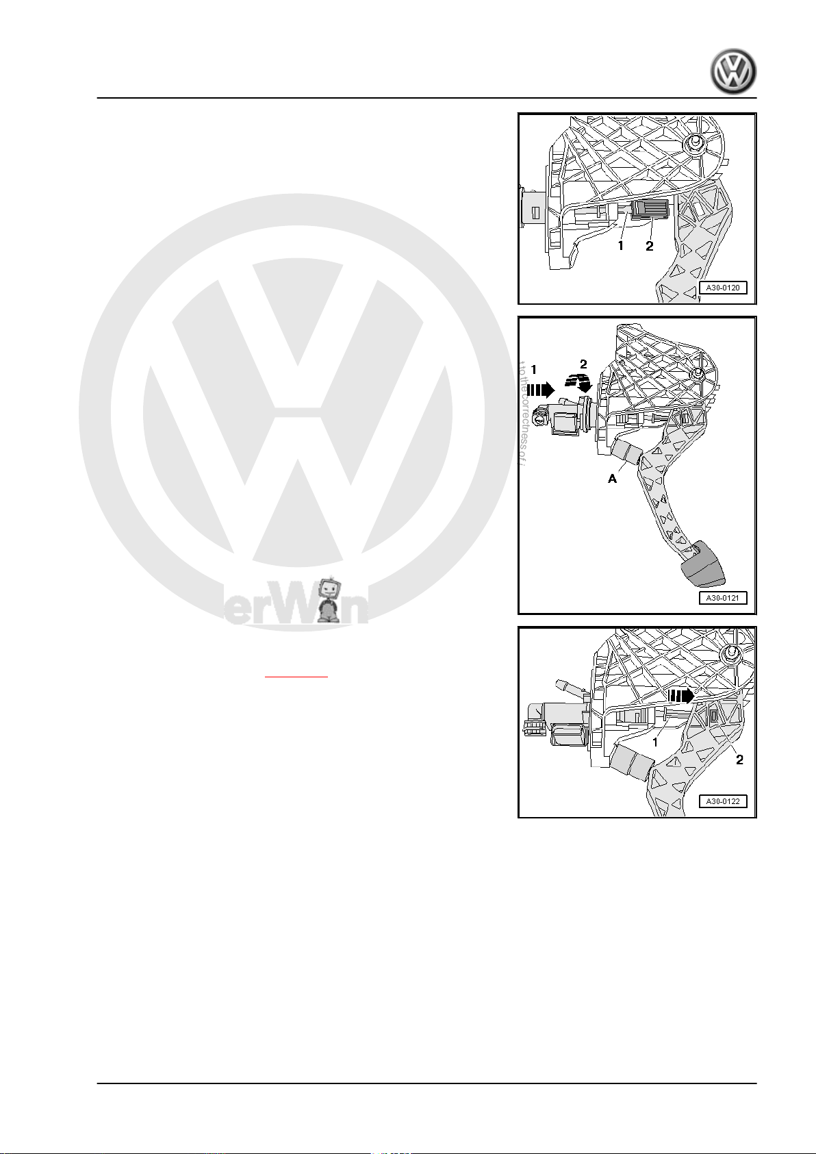
P
r
o
t
e
c
t
e
d
b
y
c
o
p
y
r
i
g
h
t
.
C
o
p
y
i
n
g
f
o
r
p
r
i
v
a
t
e
o
r
c
o
m
m
e
r
c
i
a
l
p
u
r
p
o
s
e
s
,
i
n
p
a
r
t
o
r
i
n
w
h
o
l
e
,
i
s
n
o
t
p
e
r
m
i
t
t
e
d
u
n
l
e
s
s
a
u
t
h
o
r
i
s
e
d
b
y
V
o
l
k
s
w
a
g
e
n
A
G
.
V
o
l
k
s
w
a
g
e
n
A
G
d
o
e
s
n
o
t
g
u
a
r
a
n
t
e
e
o
r
a
c
c
e
p
t
a
n
y
l
i
a
b
i
l
i
t
y
w
i
t
h
r
e
s
p
e
c
t
t
o
t
h
e
c
o
r
r
e
c
t
n
e
s
s
o
f
i
n
f
o
r
m
a
t
i
o
n
i
n
t
h
i
s
d
o
c
u
m
e
n
t
.
C
o
p
y
r
i
g
h
t
b
y
V
o
l
k
s
w
a
g
e
n
A
G
.
6-speed manual gearbox 0AG - Edition 08.2007
– Attach retainer -2- to master cylinder operating rod -1-.
– Insert spacer -A- between clutch pedal and stop and press
clutch pedal to spacer.
♦
Length of spacer = about 40 mm (e.g. 1/2" socket).
– Engage master cylinder in mounting bracket -arrow 1- and
-arrow 2-.
– Press master cylinder operating rod -1- in direction of arrow
until retainer -2- engages audibly in clutch pedal.
– Install mounting bracket ⇒ page 16 .
Jetta 2006 ➤ , Golf Variant 2008 ➤
2.7 Removing and installing clutch position sender -G476-
Special tools and workshop equipment required
2. Repairing clutch mechanism 21

P
r
o
t
e
c
t
e
d
b
y
c
o
p
y
r
i
g
h
t
.
C
o
p
y
i
n
g
f
o
r
p
r
i
v
a
t
e
o
r
c
o
m
m
e
r
c
i
a
l
p
u
r
p
o
s
e
s
,
i
n
p
a
r
t
o
r
i
n
w
h
o
l
e
,
i
s
n
o
t
p
e
r
m
i
t
t
e
d
u
n
l
e
s
s
a
u
t
h
o
r
i
s
e
d
b
y
V
o
l
k
s
w
a
g
e
n
A
G
.
V
o
l
k
s
w
a
g
e
n
A
G
d
o
e
s
n
o
t
g
u
a
r
a
n
t
e
e
o
r
a
c
c
e
p
t
a
n
y
l
i
a
b
i
l
i
t
y
w
i
t
h
r
e
s
p
e
c
t
t
o
t
h
e
c
o
r
r
e
c
t
n
e
s
s
o
f
i
n
f
o
r
m
a
t
i
o
n
i
n
t
h
i
s
d
o
c
u
m
e
n
t
.
C
o
p
y
r
i
g
h
t
b
y
V
o
l
k
s
w
a
g
e
n
A
G
.
Jetta 2006 ➤ , Golf Variant 2008 ➤
6-speed manual gearbox 0AG - Edition 08.2007
♦ Hose clamps -3094-
2.7.1 Removing
– First check whether a coded radio is fitted. If so, obtain anti-
theft code.
– Remove complete air filter housing if it is near battery ⇒ Rep.
Gr. 24 ; Repairing injection system .
– Remove battery, battery cover and battery tray ⇒ Electrical
system; Rep. Gr. 27 ; Removing and installing battery .
If a pipe/hose line or plastic line -1- with a round component is
installed directly beneath the master cylinder, the pipe/hose line
or plastic line must be removed.
♦
During the following work, ensure that no brake fluid lands on
longitudinal member or gearbox. If this does happen, clean the
affected areas thoroughly.
♦
Place a lint-free cloth under the master cylinder.
Note
– Clamp off supply hose to master cylinder using hose clamp
-3094- .
22 Rep. Gr.30 - Clutch
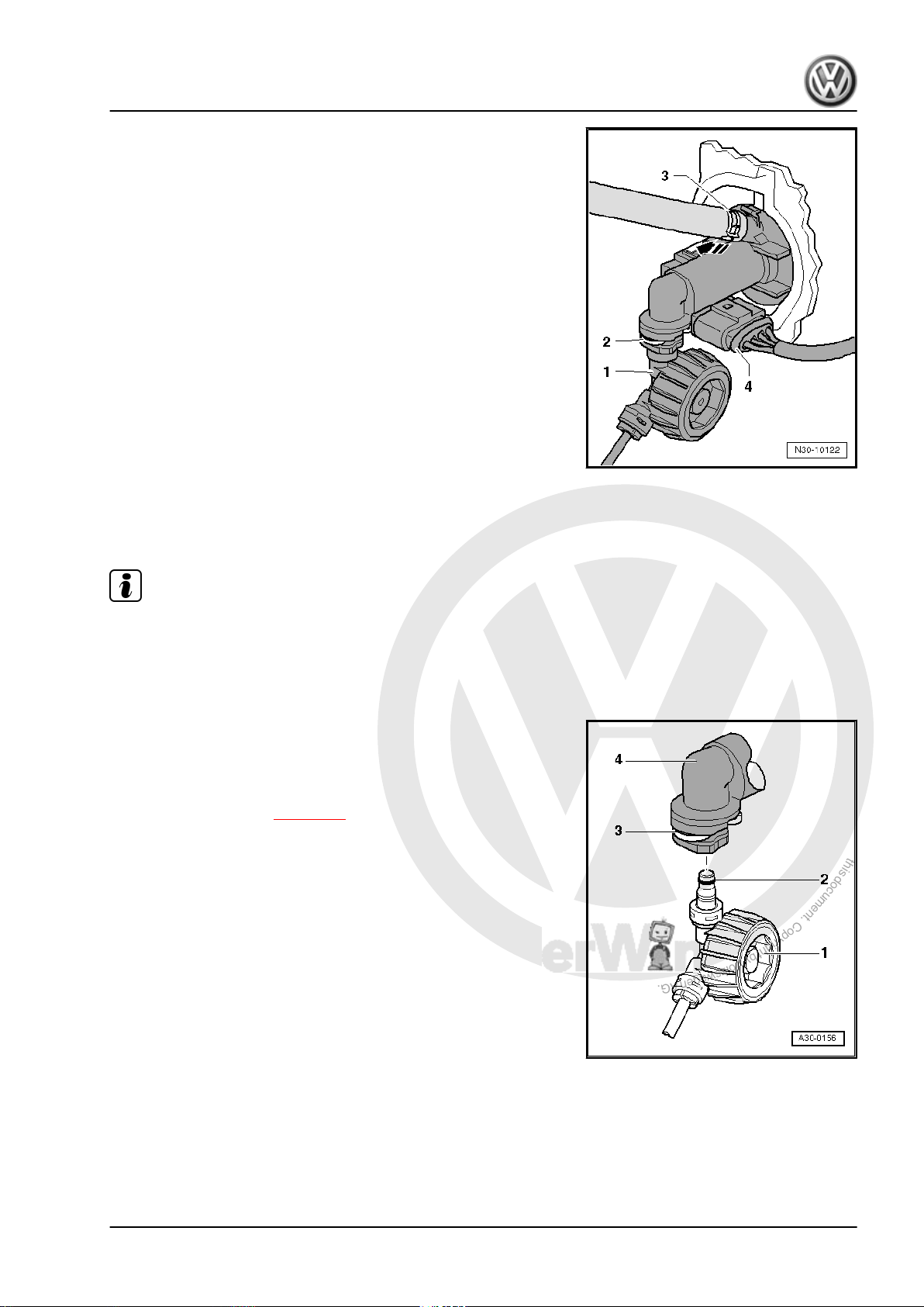
P
r
o
t
e
c
t
e
d
b
y
c
o
p
y
r
i
g
h
t
.
C
o
p
y
i
n
g
f
o
r
p
r
i
v
a
t
e
o
r
c
o
m
m
e
r
c
i
a
l
p
u
r
p
o
s
e
s
,
i
n
p
a
r
t
o
r
i
n
w
h
o
l
e
,
i
s
n
o
t
p
e
r
m
i
t
t
e
d
u
n
l
e
s
s
a
u
t
h
o
r
i
s
e
d
b
y
V
o
l
k
s
w
a
g
e
n
A
G
.
V
o
l
k
s
w
a
g
e
n
A
G
d
o
e
s
n
o
t
g
u
a
r
a
n
t
e
e
o
r
a
c
c
e
p
t
a
n
y
l
i
a
b
i
l
i
t
y
w
i
t
h
r
e
s
p
e
c
t
t
o
t
h
e
c
o
r
r
e
c
t
n
e
s
s
o
f
i
n
f
o
r
m
a
t
i
o
n
i
n
t
h
i
s
d
o
c
u
m
e
n
t
.
C
o
p
y
r
i
g
h
t
b
y
V
o
l
k
s
w
a
g
e
n
A
G
.
6-speed manual gearbox 0AG - Edition 08.2007
– Release securing clip -2- with a screwdriver and pull out of
master cylinder to stop.
– Pull pipe/hose line or plastic line -1- out from master cylinder
and seal hose.
All vehicles
– Disconnect electrical connector -4-.
– Unclip clutch position sender -G476- from master cylinder
-arrow- and remove.
2.7.2 Installing
Install in reverse order of removal. During this step, observe the
following:
Note
♦
Renew hose clips.
♦
Allocate all components according to ⇒ Electronic parts cata‐
logue “ETKA” .
If the pipe/hose line or plastic line was removed:
– Push pipe/hose line or plastic line -1- with seal -2- onto con‐
nection of master cylinder -4- until securing clip -3- engages
audibly.
– Test line by tugging on it.
– Bleed clutch system ⇒ page 27 .
All vehicles
– Install battery tray and battery⇒ Electrical system; Rep. Gr.
27 ; Removing and installing battery .
– If removed, install complete air filter housing ⇒ Rep. Gr. 24 ;
Repairing injection system .
– Reconnect battery and perform work required after connecting
battery ⇒ Electrical system; Rep. Gr. 27 ; Disconnecting and
connecting battery .
Jetta 2006 ➤ , Golf Variant 2008 ➤
2. Repairing clutch mechanism 23
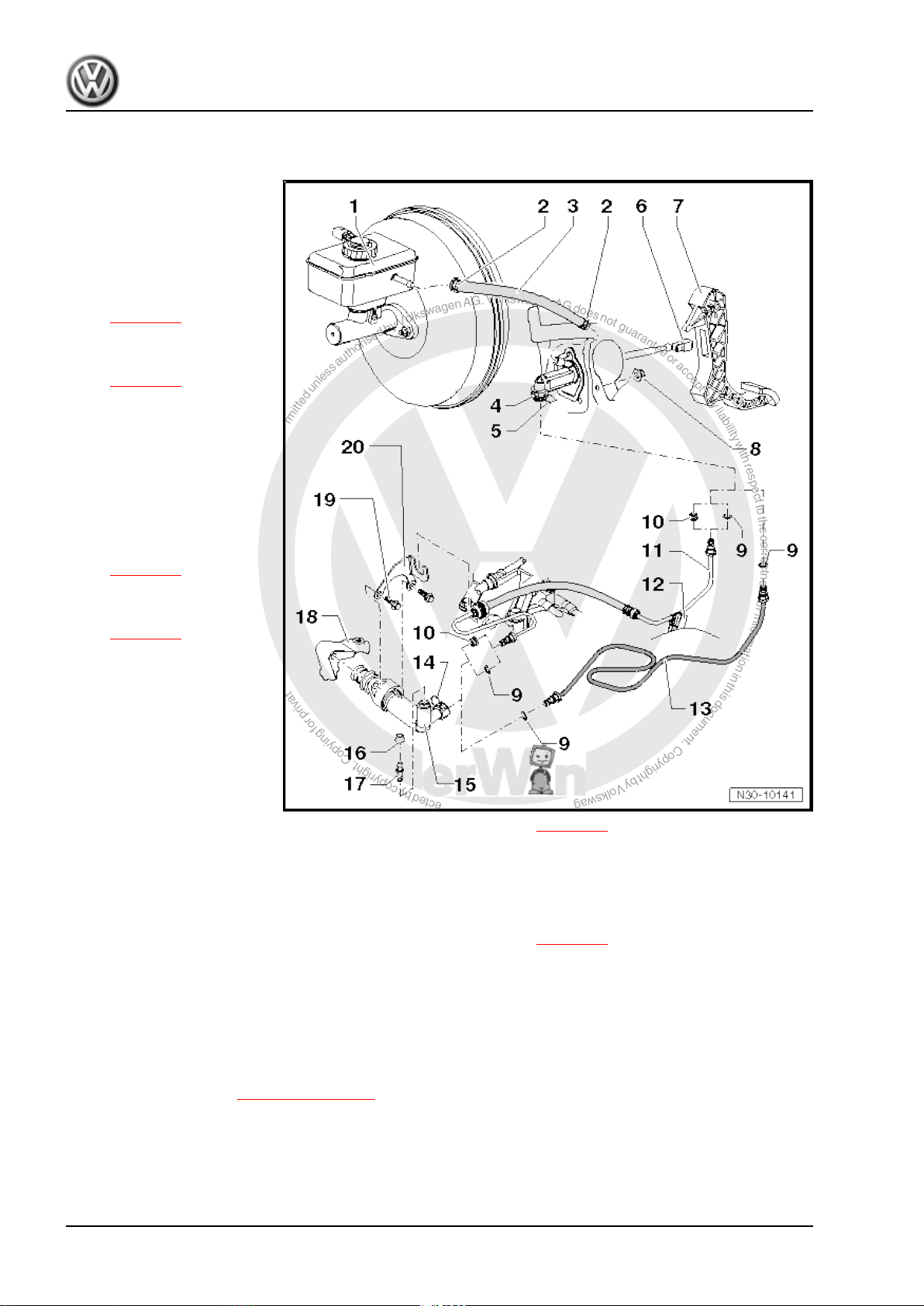
P
r
o
t
e
c
t
e
d
b
y
c
o
p
y
r
i
g
h
t
.
C
o
p
y
i
n
g
f
o
r
p
r
i
v
a
t
e
o
r
c
o
m
m
e
r
c
i
a
l
p
u
r
p
o
s
e
s
,
i
n
p
a
r
t
o
r
i
n
w
h
o
l
e
,
i
s
n
o
t
p
e
r
m
i
t
t
e
d
u
n
l
e
s
s
a
u
t
h
o
r
i
s
e
d
b
y
V
o
l
k
s
w
a
g
e
n
A
G
.
V
o
l
k
s
w
a
g
e
n
A
G
d
o
e
s
n
o
t
g
u
a
r
a
n
t
e
e
o
r
a
c
c
e
p
t
a
n
y
l
i
a
b
i
l
i
t
y
w
i
t
h
r
e
s
p
e
c
t
t
o
t
h
e
c
o
r
r
e
c
t
n
e
s
s
o
f
i
n
f
o
r
m
a
t
i
o
n
i
n
t
h
i
s
d
o
c
u
m
e
n
t
.
C
o
p
y
r
i
g
h
t
b
y
V
o
l
k
s
w
a
g
e
n
A
G
.
Jetta 2006 ➤ , Golf Variant 2008 ➤
6-speed manual gearbox 0AG - Edition 08.2007
2.8 Assembly overview - hydraulic system
1 - Brake fluid reservoir
2 - Spring-type clip
3 - Supply hose
❑ Rubber
❑ From 12.05, plastic in
some vehicles
⇒ page 25
4 - Master cylinder
❑ Removing and installing
⇒ page 19
5 - Clip
❑ Pull clip out to stop to re‐
move or install line be‐
tween master and slave
cylinders
6 - Retainer
❑ To remove and install,
separate master cylin‐
der from clutch pedal.
⇒ page 14
7 - Clutch pedal
❑ Removing and installing
⇒ page 14
8 - Self-locking hexagon nut,
25 Nm
❑ Mounting bracket to
body
❑ Always renew
9 - O-ring
❑ Pull onto line connection
❑ Insert with brake fluid
❑ Seals, O-rings depending on configuration of line connections ⇒ page 25
❑ Allocation ⇒ Electronic parts catalogue “ETKA”
10 - Seal
❑ Pull onto line connection
❑ Insert with brake fluid
❑ Seals, O-rings depending on configuration of line connections ⇒ page 25
❑ Allocation ⇒ Electronic parts catalogue “ETKA”
11 - Pipe/hose line
❑ Allocation ⇒ Electronic parts catalogue “ETKA”
❑ To remove, remove battery and battery tray ⇒ Electrical system; Rep. Gr. 27 ; Removing and installing
battery .
12 - Retainer
❑ For pipe/hose line ⇒ Item 11 (page 24)
❑ Secured to body.
13 - Plastic line
❑ Allocation ⇒ Electronic parts catalogue “ETKA”
❑ To remove, remove battery and battery tray ⇒ Electrical system; Rep. Gr. 27 ; Removing and installing
battery .
24 Rep. Gr.30 - Clutch
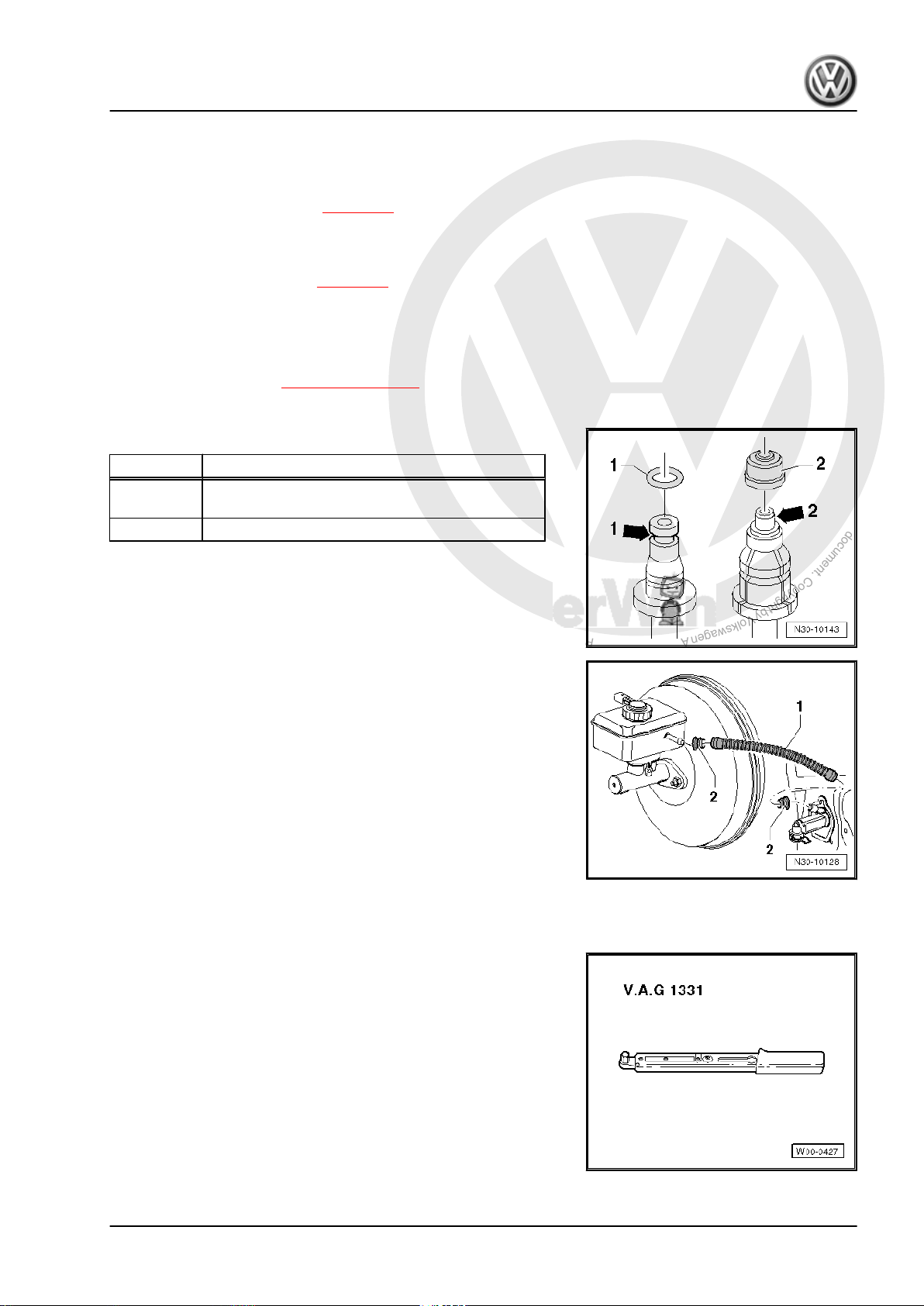
P
r
o
t
e
c
t
e
d
b
y
c
o
p
y
r
i
g
h
t
.
C
o
p
y
i
n
g
f
o
r
p
r
i
v
a
t
e
o
r
c
o
m
m
e
r
c
i
a
l
p
u
r
p
o
s
e
s
,
i
n
p
a
r
t
o
r
i
n
w
h
o
l
e
,
i
s
n
o
t
p
e
r
m
i
t
t
e
d
u
n
l
e
s
s
a
u
t
h
o
r
i
s
e
d
b
y
V
o
l
k
s
w
a
g
e
n
A
G
.
V
o
l
k
s
w
a
g
e
n
A
G
d
o
e
s
n
o
t
g
u
a
r
a
n
t
e
e
o
r
a
c
c
e
p
t
a
n
y
l
i
a
b
i
l
i
t
y
w
i
t
h
r
e
s
p
e
c
t
t
o
t
h
e
c
o
r
r
e
c
t
n
e
s
s
o
f
i
n
f
o
r
m
a
t
i
o
n
i
n
t
h
i
s
d
o
c
u
m
e
n
t
.
C
o
p
y
r
i
g
h
t
b
y
V
o
l
k
s
w
a
g
e
n
A
G
.
Jetta 2006 ➤ , Golf Variant 2008 ➤
6-speed manual gearbox 0AG - Edition 08.2007
14 - Clip
❑ Pull clip out to stop to remove or install line between master and slave cylinders
15 - Slave cylinder
❑ Removing and installing ⇒ page 25
16 - Dust cap
17 - Bleeder valve
❑ Bleeding clutch system ⇒ page 27
18 - Gearbox
19 - Hexagon bolt, 20 Nm
20 - Retainer
❑ For pipe/hose line ⇒ Item 11 (page 24)
Seals and O-rings for pipe/hose line and for plastic line
Item Version of line connection
1 Line connection with circumferential groove
2 Line connection with shoulder -arrow 2-
-arrow 1-
From 12.05, plastic supply hose -1- in some vehicles.
• The seals -2- must be located in supply hose.
2.9 Removing and installing slave cylinder
Special tools and workshop equipment required
♦ Torque wrench -V.A.G 1331-
2. Repairing clutch mechanism 25

P
r
o
t
e
c
t
e
d
b
y
c
o
p
y
r
i
g
h
t
.
C
o
p
y
i
n
g
f
o
r
p
r
i
v
a
t
e
o
r
c
o
m
m
e
r
c
i
a
l
p
u
r
p
o
s
e
s
,
i
n
p
a
r
t
o
r
i
n
w
h
o
l
e
,
i
s
n
o
t
p
e
r
m
i
t
t
e
d
u
n
l
e
s
s
a
u
t
h
o
r
i
s
e
d
b
y
V
o
l
k
s
w
a
g
e
n
A
G
.
V
o
l
k
s
w
a
g
e
n
A
G
d
o
e
s
n
o
t
g
u
a
r
a
n
t
e
e
o
r
a
c
c
e
p
t
a
n
y
l
i
a
b
i
l
i
t
y
w
i
t
h
r
e
s
p
e
c
t
t
o
t
h
e
c
o
r
r
e
c
t
n
e
s
s
o
f
i
n
f
o
r
m
a
t
i
o
n
i
n
t
h
i
s
d
o
c
u
m
e
n
t
.
C
o
p
y
r
i
g
h
t
b
y
V
o
l
k
s
w
a
g
e
n
A
G
.
Jetta 2006 ➤ , Golf Variant 2008 ➤
6-speed manual gearbox 0AG - Edition 08.2007
2.9.1 Removing
– First check whether a coded radio is fitted. If so, obtain anti-
theft code.
– With ignition switched off, disconnect battery ⇒ Electrical sys‐
tem; Rep. Gr. 27 ; Disconnecting and connecting battery .
– Remove complete air filter housing if it is near slave cylinder
⇒ Rep. Gr. 24 ; Repairing injection system .
– Remove securing clip for gear selector cable -arrow 1- from
gearbox selector lever -A-.
– Pull gear selector cable from pin.
Metal relay lever
– Remove securing clip -arrow 2- for gate selector cable from
relay lever -B-.
– Pull gate selector cable from pin.
– Pull securing clip -arrow 3- off relay lever -B- and remove relay
lever.
Plastic relay lever
– Remove relay lever together with cable end-piece from gear‐
box ⇒ page 50 .
Continuation for all
– Remove gearbox selector lever -A- by removing nut
-arrow 4-.
– Remove cable support bracket from gearbox -arrows-.
– Then tie up selector cable and gate cable.
– Place a lint-free cloth under slave cylinder.
– Pull clip -A- for line between master and slave cylinders out of
slave cylinder to stop.
– Pull line between master and slave cylinders out of support
-C-, if present.
– Pull line between master and slave cylinders -B- out of slave
cylinder and seal opening.
– Unbolt slave cylinder -arrows- and remove.
Note
Do not depress clutch pedal.
26 Rep. Gr.30 - Clutch
 Loading...