

Page 1

P
r
o
t
e
c
t
e
d
b
y
c
o
p
y
r
i
g
h
t
.
C
o
p
y
i
n
g
f
o
r
p
r
i
v
a
t
e
o
r
c
o
m
m
e
r
c
i
a
l
p
u
r
p
o
s
e
s
,
i
n
p
a
r
t
o
r
i
n
w
h
o
l
e
,
i
s
n
o
t
p
e
r
m
i
t
t
e
d
u
n
l
e
s
s
a
u
t
h
o
r
i
s
e
d
b
y
V
o
l
k
s
w
a
g
e
n
A
G
.
V
o
l
k
s
w
a
g
e
n
A
G
d
o
e
s
n
o
t
g
u
a
r
a
n
t
e
e
o
r
a
c
c
e
p
t
a
n
y
l
i
a
b
i
l
i
t
y
w
i
t
h
r
e
s
p
e
c
t
t
o
t
h
e
c
o
r
r
e
c
t
n
e
s
s
o
f
i
n
f
o
r
m
a
t
i
o
n
i
n
t
h
i
s
d
o
c
u
m
e
n
t
.
C
o
p
y
r
i
g
h
t
b
y
V
o
l
k
s
w
a
g
e
n
A
G
.
Service
Repair Manual
Jetta Hybrid 2013 ➤
Direct Shift Gearbox
Edition 01.2016
Service Department. Technical Information
Page 2

P
r
o
t
e
c
t
e
d
b
y
c
o
p
y
r
i
g
h
t
.
C
o
p
y
i
n
g
f
o
r
p
r
i
v
a
t
e
o
r
c
o
m
m
e
r
c
i
a
l
p
u
r
p
o
s
e
s
,
i
n
p
a
r
t
o
r
i
n
w
h
o
l
e
,
i
s
n
o
t
p
e
r
m
i
t
t
e
d
u
n
l
e
s
s
a
u
t
h
o
r
i
s
e
d
b
y
V
o
l
k
s
w
a
g
e
n
A
G
.
V
o
l
k
s
w
a
g
e
n
A
G
d
o
e
s
n
o
t
g
u
a
r
a
n
t
e
e
o
r
a
c
c
e
p
t
a
n
y
l
i
a
b
i
l
i
t
y
w
i
t
h
r
e
s
p
e
c
t
t
o
t
h
e
c
o
r
r
e
c
t
n
e
s
s
o
f
i
n
f
o
r
m
a
t
i
o
n
i
n
t
h
i
s
d
o
c
u
m
e
n
t
.
C
o
p
y
r
i
g
h
t
b
y
V
o
l
k
s
w
a
g
e
n
A
G
.
List of Workshop Manual Repair Groups
Re pa ir G ro up
00 - General, Technical Data
30 - Clutch
34 - Controls, Housing
35 - Gears, Shafts
39 - Final Drive, Differential
Service
Technical information should always be available to the foremen and mechanics, because their
careful and constant adherence to the instructions is essential to ensure vehicle road-worthiness and
safety. In addition, the normal basic safety precautions for working on motor vehicles must, as a
matter of course, be observed.
All rights reserved.
No reproduction without prior agreement from publisher.
Copyright © 2016 Volkswagen AG, Wolfsburg D4B8026057D
Page 3

P
r
o
t
e
c
t
e
d
b
y
c
o
p
y
r
i
g
h
t
.
C
o
p
y
i
n
g
f
o
r
p
r
i
v
a
t
e
o
r
c
o
m
m
e
r
c
i
a
l
p
u
r
p
o
s
e
s
,
i
n
p
a
r
t
o
r
i
n
w
h
o
l
e
,
i
s
n
o
t
p
e
r
m
i
t
t
e
d
u
n
l
e
s
s
a
u
t
h
o
r
i
s
e
d
b
y
V
o
l
k
s
w
a
g
e
n
A
G
.
V
o
l
k
s
w
a
g
e
n
A
G
d
o
e
s
n
o
t
g
u
a
r
a
n
t
e
e
o
r
a
c
c
e
p
t
a
n
y
l
i
a
b
i
l
i
t
y
w
i
t
h
r
e
s
p
e
c
t
t
o
t
h
e
c
o
r
r
e
c
t
n
e
s
s
o
f
i
n
f
o
r
m
a
t
i
o
n
i
n
t
h
i
s
d
o
c
u
m
e
n
t
.
C
o
p
y
r
i
g
h
t
b
y
V
o
l
k
s
w
a
g
e
n
A
G
.
Jetta Hybrid 2013 ➤
Direct Shift Gearbox - Edition 01.2016
Contents
00 - General, Technical Data . . . . . . . . . . . . . . . . . . . . . . . . . . . . . . . . . . . . . . . . . . . . 1
1 Identification . . . . . . . . . . . . . . . . . . . . . . . . . . . . . . . . . . . . . . . . . . . . . . . . . . . . . . . . . . . . 1
1.1 Transmission Identification . . . . . . . . . . . . . . . . . . . . . . . . . . . . . . . . . . . . . . . . . . . . . . . . . . 1
2 Safety Precautions . . . . . . . . . . . . . . . . . . . . . . . . . . . . . . . . . . . . . . . . . . . . . . . . . . . . . . . . 2
2.1 General Safety Precautions . . . . . . . . . . . . . . . . . . . . . . . . . . . . . . . . . . . . . . . . . . . . . . . . 2
2.2 High Voltage Vehicles Safety Precautions . . . . . . . . . . . . . . . . . . . . . . . . . . . . . . . . . . . . . . 2
2.3 Road Test with Testing Equipment Safety Precautions . . . . . . . . . . . . . . . . . . . . . . . . . . . . 3
2.4 Mechatronic Safety Precautions . . . . . . . . . . . . . . . . . . . . . . . . . . . . . . . . . . . . . . . . . . . . . . 3
2.5 Towing Notes . . . . . . . . . . . . . . . . . . . . . . . . . . . . . . . . . . . . . . . . . . . . . . . . . . . . . . . . . . . . 5
3 Repair Information . . . . . . . . . . . . . . . . . . . . . . . . . . . . . . . . . . . . . . . . . . . . . . . . . . . . . . . . 6
3.1 General Information . . . . . . . . . . . . . . . . . . . . . . . . . . . . . . . . . . . . . . . . . . . . . . . . . . . . . . 6
3.2 Guidelines for Clean Working Conditions . . . . . . . . . . . . . . . . . . . . . . . . . . . . . . . . . . . . . . 8
3.3 General Repair Information . . . . . . . . . . . . . . . . . . . . . . . . . . . . . . . . . . . . . . . . . . . . . . . . 8
4 Technical Data . . . . . . . . . . . . . . . . . . . . . . . . . . . . . . . . . . . . . . . . . . . . . . . . . . . . . . . . . . 12
4.1 Transmission/Engine Allocation . . . . . . . . . . . . . . . . . . . . . . . . . . . . . . . . . . . . . . . . . . . . . . 12
4.2 Gear Ratio Calculation . . . . . . . . . . . . . . . . . . . . . . . . . . . . . . . . . . . . . . . . . . . . . . . . . . . . 12
4.3 Capacities . . . . . . . . . . . . . . . . . . . . . . . . . . . . . . . . . . . . . . . . . . . . . . . . . . . . . . . . . . . . . . 13
5 Overview - Powertrain . . . . . . . . . . . . . . . . . . . . . . . . . . . . . . . . . . . . . . . . . . . . . . . . . . . . 14
5.1 Overview - Powertrain, Front Wheel Drive . . . . . . . . . . . . . . . . . . . . . . . . . . . . . . . . . . . . . . 14
30 - Clutch . . . . . . . . . . . . . . . . . . . . . . . . . . . . . . . . . . . . . . . . . . . . . . . . . . . . . . . . . . 15
1 Clutch Mechanism . . . . . . . . . . . . . . . . . . . . . . . . . . . . . . . . . . . . . . . . . . . . . . . . . . . . . . . . 15
1.1 Overview - Clutch Engaging Mechanism . . . . . . . . . . . . . . . . . . . . . . . . . . . . . . . . . . . . . . 15
1.2 Clutch Engaging Mechanism, Removing and Installing . . . . . . . . . . . . . . . . . . . . . . . . . . . . 16
1.3 Clutch Engaging Mechanism, Adjusting . . . . . . . . . . . . . . . . . . . . . . . . . . . . . . . . . . . . . . . . 19
2 Clutch . . . . . . . . . . . . . . . . . . . . . . . . . . . . . . . . . . . . . . . . . . . . . . . . . . . . . . . . . . . . . . . . . . 32
2.1 Overview - Dual Clutch . . . . . . . . . . . . . . . . . . . . . . . . . . . . . . . . . . . . . . . . . . . . . . . . . . . . 32
2.2 DSG® Clutch, Removing . . . . . . . . . . . . . . . . . . . . . . . . . . . . . . . . . . . . . . . . . . . . . . . . . . 33
2.3 Dual Clutch, Installing . . . . . . . . . . . . . . . . . . . . . . . . . . . . . . . . . . . . . . . . . . . . . . . . . . . . . . 37
2.4 Input Shaft Seal, Replacing . . . . . . . . . . . . . . . . . . . . . . . . . . . . . . . . . . . . . . . . . . . . . . . . 41
2.5 Inner Input Shaft Seal, Replacing . . . . . . . . . . . . . . . . . . . . . . . . . . . . . . . . . . . . . . . . . . . . 43
3 Special Tools . . . . . . . . . . . . . . . . . . . . . . . . . . . . . . . . . . . . . . . . . . . . . . . . . . . . . . . . . . . . 45
34 - Controls, Housing . . . . . . . . . . . . . . . . . . . . . . . . . . . . . . . . . . . . . . . . . . . . . . . . 48
1 Mechatronic . . . . . . . . . . . . . . . . . . . . . . . . . . . . . . . . . . . . . . . . . . . . . . . . . . . . . . . . . . . . 48
1.1 Overview - Mechatronic . . . . . . . . . . . . . . . . . . . . . . . . . . . . . . . . . . . . . . . . . . . . . . . . . . . . 48
1.2 Mechatronic, Removing and Installing . . . . . . . . . . . . . . . . . . . . . . . . . . . . . . . . . . . . . . . . 50
1.3 Mechatronic, Moving into Removal Position by Hand . . . . . . . . . . . . . . . . . . . . . . . . . . . . 69
2 Selector Mechanism . . . . . . . . . . . . . . . . . . . . . . . . . . . . . . . . . . . . . . . . . . . . . . . . . . . . . . 71
2.1 Overview - Selector Mechanism . . . . . . . . . . . . . . . . . . . . . . . . . . . . . . . . . . . . . . . . . . . . . . 71
2.2 Emergency Release from P . . . . . . . . . . . . . . . . . . . . . . . . . . . . . . . . . . . . . . . . . . . . . . . . 73
2.3 Selector Lever Handle, Removing and Installing . . . . . . . . . . . . . . . . . . . . . . . . . . . . . . . . 74
2.4 Button in Handle, Moving Into Installation Position . . . . . . . . . . . . . . . . . . . . . . . . . . . . . . 75
2.5 Selector Mechanism, Removing and Installing . . . . . . . . . . . . . . . . . . . . . . . . . . . . . . . . . . 77
2.6 Gearshift Mechanism, Checking . . . . . . . . . . . . . . . . . . . . . . . . . . . . . . . . . . . . . . . . . . . . 86
2.7 Selector Lever Cable, Checking and Adjusting . . . . . . . . . . . . . . . . . . . . . . . . . . . . . . . . . . 87
2.8 Selector Shaft Seal, Replacing . . . . . . . . . . . . . . . . . . . . . . . . . . . . . . . . . . . . . . . . . . . . . . 90
3 Transmission, Removing and Installing . . . . . . . . . . . . . . . . . . . . . . . . . . . . . . . . . . . . . . . . 91
3.1 Transmission, Removing . . . . . . . . . . . . . . . . . . . . . . . . . . . . . . . . . . . . . . . . . . . . . . . . . . 91
3.2 Transmission, Installing . . . . . . . . . . . . . . . . . . . . . . . . . . . . . . . . . . . . . . . . . . . . . . . . . . . . 95
3.3 Transmission Tightening Specifications . . . . . . . . . . . . . . . . . . . . . . . . . . . . . . . . . . . . . . . . 99
Contents i
Page 4

P
r
o
t
e
c
t
e
d
b
y
c
o
p
y
r
i
g
h
t
.
C
o
p
y
i
n
g
f
o
r
p
r
i
v
a
t
e
o
r
c
o
m
m
e
r
c
i
a
l
p
u
r
p
o
s
e
s
,
i
n
p
a
r
t
o
r
i
n
w
h
o
l
e
,
i
s
n
o
t
p
e
r
m
i
t
t
e
d
u
n
l
e
s
s
a
u
t
h
o
r
i
s
e
d
b
y
V
o
l
k
s
w
a
g
e
n
A
G
.
V
o
l
k
s
w
a
g
e
n
A
G
d
o
e
s
n
o
t
g
u
a
r
a
n
t
e
e
o
r
a
c
c
e
p
t
a
n
y
l
i
a
b
i
l
i
t
y
w
i
t
h
r
e
s
p
e
c
t
t
o
t
h
e
c
o
r
r
e
c
t
n
e
s
s
o
f
i
n
f
o
r
m
a
t
i
o
n
i
n
t
h
i
s
d
o
c
u
m
e
n
t
.
C
o
p
y
r
i
g
h
t
b
y
V
o
l
k
s
w
a
g
e
n
A
G
.
Jetta Hybrid 2013 ➤
Direct Shift Gearbox - Edition 01.2016
4 Transmission, Transporting . . . . . . . . . . . . . . . . . . . . . . . . . . . . . . . . . . . . . . . . . . . . . . . . 100
5 Securing on Engine and Transmission Holder . . . . . . . . . . . . . . . . . . . . . . . . . . . . . . . . . . 102
6 Subframe Mount . . . . . . . . . . . . . . . . . . . . . . . . . . . . . . . . . . . . . . . . . . . . . . . . . . . . . . . . . . 103
6.1 Overview - Subframe Mount . . . . . . . . . . . . . . . . . . . . . . . . . . . . . . . . . . . . . . . . . . . . . . . . 103
7 Transmission Fluid . . . . . . . . . . . . . . . . . . . . . . . . . . . . . . . . . . . . . . . . . . . . . . . . . . . . . . . . 111
7.1 Transmission Fluid, Draining and Filling . . . . . . . . . . . . . . . . . . . . . . . . . . . . . . . . . . . . . . 111
8 Special Tools . . . . . . . . . . . . . . . . . . . . . . . . . . . . . . . . . . . . . . . . . . . . . . . . . . . . . . . . . . . . 116
35 - Gears, Shafts . . . . . . . . . . . . . . . . . . . . . . . . . . . . . . . . . . . . . . . . . . . . . . . . . . . . 121
39 - Final Drive, Differential . . . . . . . . . . . . . . . . . . . . . . . . . . . . . . . . . . . . . . . . . . . . . . 126
1 Parking Lock . . . . . . . . . . . . . . . . . . . . . . . . . . . . . . . . . . . . . . . . . . . . . . . . . . . . . . . . . . . . 121
1.1 Parking Lock Cover, Removing and Installing . . . . . . . . . . . . . . . . . . . . . . . . . . . . . . . . . . 121
1.2 Parking Lock, Removing and Installing . . . . . . . . . . . . . . . . . . . . . . . . . . . . . . . . . . . . . . . . 123
2 Special Tools . . . . . . . . . . . . . . . . . . . . . . . . . . . . . . . . . . . . . . . . . . . . . . . . . . . . . . . . . . . . 125
1 Seals . . . . . . . . . . . . . . . . . . . . . . . . . . . . . . . . . . . . . . . . . . . . . . . . . . . . . . . . . . . . . . . . . . 126
1.1 Overview - Component Location Seals . . . . . . . . . . . . . . . . . . . . . . . . . . . . . . . . . . . . . . . . 126
1.2 Left Seal, Replacing . . . . . . . . . . . . . . . . . . . . . . . . . . . . . . . . . . . . . . . . . . . . . . . . . . . . . . 126
1.3 Right Seal, Replacing . . . . . . . . . . . . . . . . . . . . . . . . . . . . . . . . . . . . . . . . . . . . . . . . . . . . . . 129
2 Special Tools . . . . . . . . . . . . . . . . . . . . . . . . . . . . . . . . . . . . . . . . . . . . . . . . . . . . . . . . . . . . 132
3 Revision History . . . . . . . . . . . . . . . . . . . . . . . . . . . . . . . . . . . . . . . . . . . . . . . . . . . . . . . . . . 133
ii Contents
Page 5
P
r
o
t
e
c
t
e
d
b
y
c
o
p
y
r
i
g
h
t
.
C
o
p
y
i
n
g
f
o
r
p
r
i
v
a
t
e
o
r
c
o
m
m
e
r
c
i
a
l
p
u
r
p
o
s
e
s
,
i
n
p
a
r
t
o
r
i
n
w
h
o
l
e
,
i
s
n
o
t
p
e
r
m
i
t
t
e
d
u
n
l
e
s
s
a
u
t
h
o
r
i
s
e
d
b
y
V
o
l
k
s
w
a
g
e
n
A
G
.
V
o
l
k
s
w
a
g
e
n
A
G
d
o
e
s
n
o
t
g
u
a
r
a
n
t
e
e
o
r
a
c
c
e
p
t
a
n
y
l
i
a
b
i
l
i
t
y
w
i
t
h
r
e
s
p
e
c
t
t
o
t
h
e
c
o
r
r
e
c
t
n
e
s
s
o
f
i
n
f
o
r
m
a
t
i
o
n
i
n
t
h
i
s
d
o
c
u
m
e
n
t
.
C
o
p
y
r
i
g
h
t
b
y
V
o
l
k
s
w
a
g
e
n
A
G
.
00 – General, Technical Data
Jetta Hybrid 2013 ➤
Direct Shift Gearbox - Edition 01.2016
1 Identification
(Edition 01.2016)
⇒ “1.1 Transmission Identification”, page 1
1.1 Transmission Identification
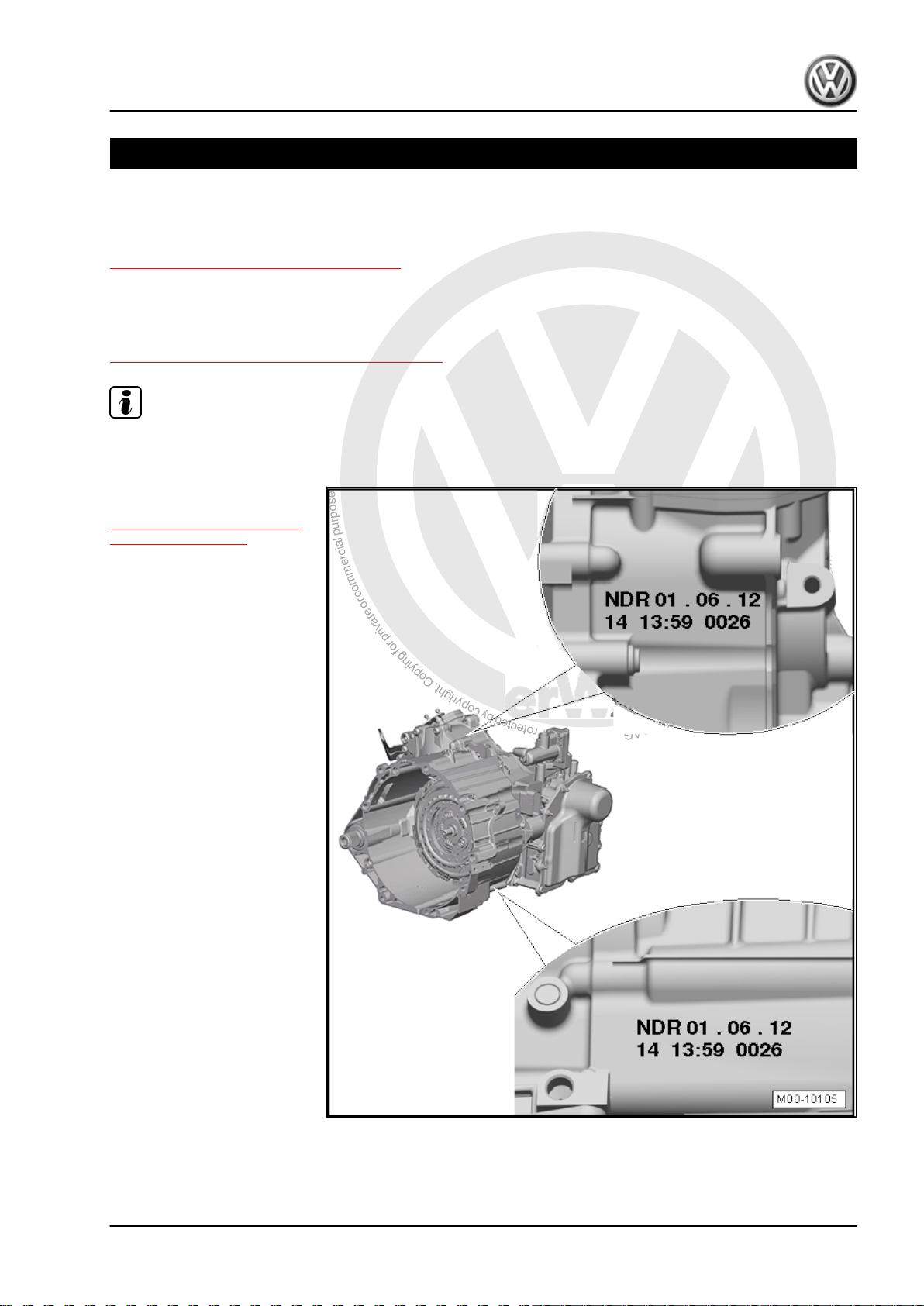
The “7-speed DSG® transmission 0CG” is installed in the Jetta
from MY 11. Allocation. Refer to
⇒ “4.1 Transmission/Engine Allocation”, page 12 .
Note
The transmission code letters are also included on the vehicle data labels.
NDR - Transmission Code
⇒ “4.1 Transmission/Engine
Allocation”, page 12
01. 06.12 - Build date:
06/01/2013
14 - Plant Code
13:59 - Time
0026 - Serial Number
1. Identification 1
Page 6
P
r
o
t
e
c
t
e
d
b
y
c
o
p
y
r
i
g
h
t
.
C
o
p
y
i
n
g
f
o
r
p
r
i
v
a
t
e
o
r
c
o
m
m
e
r
c
i
a
l
p
u
r
p
o
s
e
s
,
i
n
p
a
r
t
o
r
i
n
w
h
o
l
e
,
i
s
n
o
t
p
e
r
m
i
t
t
e
d
u
n
l
e
s
s
a
u
t
h
o
r
i
s
e
d
b
y
V
o
l
k
s
w
a
g
e
n
A
G
.
V
o
l
k
s
w
a
g
e
n
A
G
d
o
e
s
n
o
t
g
u
a
r
a
n
t
e
e
o
r
a
c
c
e
p
t
a
n
y
l
i
a
b
i
l
i
t
y
w
i
t
h
r
e
s
p
e
c
t
t
o
t
h
e
c
o
r
r
e
c
t
n
e
s
s
o
f
i
n
f
o
r
m
a
t
i
o
n
i
n
t
h
i
s
d
o
c
u
m
e
n
t
.
C
o
p
y
r
i
g
h
t
b
y
V
o
l
k
s
w
a
g
e
n
A
G
.
Jetta Hybrid 2013 ➤
Direct Shift Gearbox - Edition 01.2016
2 Safety Precautions
⇒ “2.1 General Safety Precautions”, page 2
⇒ “2.2 High Voltage Vehicles Safety Precautions”, page 2
⇒ “2.3 Road Test with Testing Equipment Safety Precautions”,
page 3
⇒ “2.4 Mechatronic Safety Precautions”, page 3
⇒ “2.5 Towing Notes”, page 5
2.1 General Safety Precautions
To Avoid Injury and Damage to the Vehicle, Observe the Follow‐
ing:
There is a risk of injury and accident from accidentally engag‐
ing a gear when the engine is running.
♦ Move the selector lever into “P” and set the parking brake
WARNING
before working on a running engine.
Observe the following to Prevent Personal Injury and Damage to
the Electrical/Electronic Components:
♦ Connect and disconnect test equipment only when the ignition
is off.
Caution
Risk of damaging electronic components when disconnecting
the battery.
♦ Follow the steps when disconnecting the battery. Refer to
⇒ Electrical Equipment; Rep. Gr. 27 ; Battery, Discon‐
necting and Connecting .
2.2 High Voltage Vehicles Safety Precau‐
tions
Note
Check with the importer if there are any questions regarding the
titles “hybrid electrically instructed person”, “high voltage techni‐
cian”, “high voltage expert”” or the term hybrid system.
Before beginning work on the high voltage system, a high voltage
technician must de-energize the high voltage system. Refer to ⇒
Electrical System Hybrid; Rep. Gr. 93 ; High Voltage System, DeEnergizing .
The procedures required for de-energizing the high voltage sys‐
tem are listed in “Working on the High Voltage System”. Refer to
⇒ Electrical System Hybrid; Rep. Gr. 93 ; High Voltage System
General Warnings .
2 Rep. Gr.00 - General, Technical Data
Page 7
P
r
o
t
e
c
t
e
d
b
y
c
o
p
y
r
i
g
h
t
.
C
o
p
y
i
n
g
f
o
r
p
r
i
v
a
t
e
o
r
c
o
m
m
e
r
c
i
a
l
p
u
r
p
o
s
e
s
,
i
n
p
a
r
t
o
r
i
n
w
h
o
l
e
,
i
s
n
o
t
p
e
r
m
i
t
t
e
d
u
n
l
e
s
s
a
u
t
h
o
r
i
s
e
d
b
y
V
o
l
k
s
w
a
g
e
n
A
G
.
V
o
l
k
s
w
a
g
e
n
A
G
d
o
e
s
n
o
t
g
u
a
r
a
n
t
e
e
o
r
a
c
c
e
p
t
a
n
y
l
i
a
b
i
l
i
t
y
w
i
t
h
r
e
s
p
e
c
t
t
o
t
h
e
c
o
r
r
e
c
t
n
e
s
s
o
f
i
n
f
o
r
m
a
t
i
o
n
i
n
t
h
i
s
d
o
c
u
m
e
n
t
.
C
o
p
y
r
i
g
h
t
b
y
V
o
l
k
s
w
a
g
e
n
A
G
.
WARNING
Jetta Hybrid 2013 ➤
Direct Shift Gearbox - Edition 01.2016
Beware of the danger of electrocution.
An electrical shock can result in death.
Follow the High Voltage System General Warnings. Refer to
⇒ Electrical System Hybrid; Rep. Gr. 93 ; High Voltage System
General Warnings .
♦ A high voltage technician must de-energize the high volt‐
age system before any can work can be performed on the
high voltage system or before any servicing work can be
performed on the body. The table “de-energizing the high
voltage system” lists all the work procedures for which this
procedure is necessary. Refer to ⇒ Electrical System Hy‐
brid; Rep. Gr. 93 ; General Warnings When Working On
The High Voltage System .
♦ Only hybrid electrically instructed persons may perform all
work on a vehicle with a high voltage system. All work
must be performed by a high voltage technician.
WARNING
Handling the high voltage cables:
♦ Do not lean on or set tools on the high voltage system or
any of its components.
♦ When working near high voltage components and high
voltage cables, do not use tools that generate heat or that
have sharp edges.
♦ Do not weld, solder or use hot air or thermal adhesive
equipment when working near high voltage components
and cables because they are sources of heat.
♦ Do not excessively bend or flex high voltage cables.
♦ Always contact a high voltage technician if there are ques‐
tions or if something is not clearly understood.
2.3 Road Test with Testing Equipment Safety Precautions
Performing Road Tests While Using Testing Equipment:
WARNING
Distraction and testing equipment that is not secured properly
can cause accidents.
The passenger airbag could pose a risk if it deploys in a colli‐
sion.
• Operating testing equipment while driving is a distraction.
• Testing equipment that is not secured probably increases
the risk of injury.
♦ Always secure testers on the rear seat with a strap and
have a second person on the rear seat operate them.
2.4 Mechatronic Safety Precautions
2. Safety Precautions 3
Page 8
P
r
o
t
e
c
t
e
d
b
y
c
o
p
y
r
i
g
h
t
.
C
o
p
y
i
n
g
f
o
r
p
r
i
v
a
t
e
o
r
c
o
m
m
e
r
c
i
a
l
p
u
r
p
o
s
e
s
,
i
n
p
a
r
t
o
r
i
n
w
h
o
l
e
,
i
s
n
o
t
p
e
r
m
i
t
t
e
d
u
n
l
e
s
s
a
u
t
h
o
r
i
s
e
d
b
y
V
o
l
k
s
w
a
g
e
n
A
G
.
V
o
l
k
s
w
a
g
e
n
A
G
d
o
e
s
n
o
t
g
u
a
r
a
n
t
e
e
o
r
a
c
c
e
p
t
a
n
y
l
i
a
b
i
l
i
t
y
w
i
t
h
r
e
s
p
e
c
t
t
o
t
h
e
c
o
r
r
e
c
t
n
e
s
s
o
f
i
n
f
o
r
m
a
t
i
o
n
i
n
t
h
i
s
d
o
c
u
m
e
n
t
.
C
o
p
y
r
i
g
h
t
b
y
V
o
l
k
s
w
a
g
e
n
A
G
.
Jetta Hybrid 2013 ➤
Direct Shift Gearbox - Edition 01.2016
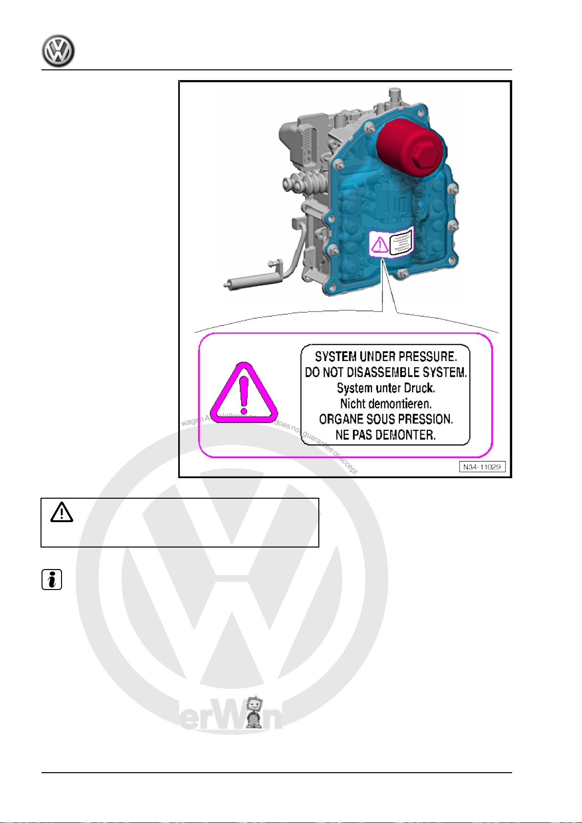
WARNING
The system is under pressure.
The pressure reservoir holds a maximum pressure of 60 bar (870 psi). The pump software adjusts the pressure.
The pump shuts off when this pressure is reached. The pump turns back on when the pressure falls below 42
bar (609 psi) caused by shifting. A pressure of up to approximately 75 bar (1087 psi) could be produced should
the software be faulty. The pressure relief valve opens automatically when this pressure is reached.
Note
4 Rep. Gr.00 - General, Technical Data
Page 9

P
r
o
t
e
c
t
e
d
b
y
c
o
p
y
r
i
g
h
t
.
C
o
p
y
i
n
g
f
o
r
p
r
i
v
a
t
e
o
r
c
o
m
m
e
r
c
i
a
l
p
u
r
p
o
s
e
s
,
i
n
p
a
r
t
o
r
i
n
w
h
o
l
e
,
i
s
n
o
t
p
e
r
m
i
t
t
e
d
u
n
l
e
s
s
a
u
t
h
o
r
i
s
e
d
b
y
V
o
l
k
s
w
a
g
e
n
A
G
.
V
o
l
k
s
w
a
g
e
n
A
G
d
o
e
s
n
o
t
g
u
a
r
a
n
t
e
e
o
r
a
c
c
e
p
t
a
n
y
l
i
a
b
i
l
i
t
y
w
i
t
h
r
e
s
p
e
c
t
t
o
t
h
e
c
o
r
r
e
c
t
n
e
s
s
o
f
i
n
f
o
r
m
a
t
i
o
n
i
n
t
h
i
s
d
o
c
u
m
e
n
t
.
C
o
p
y
r
i
g
h
t
b
y
V
o
l
k
s
w
a
g
e
n
A
G
.
2.5 Towing Notes
Caution
Danger of causing damage to the transmission.
♦ When towing the vehicle, move the selector lever into “N”.
Do not tow the vehicle further than 50 km (31 miles) and
do not drive faster than 50 km/h (31 mph).
Note
It is not possible to tow-start the engine.
Jetta Hybrid 2013 ➤
Direct Shift Gearbox - Edition 01.2016
2. Safety Precautions 5
Page 10
P
r
o
t
e
c
t
e
d
b
y
c
o
p
y
r
i
g
h
t
.
C
o
p
y
i
n
g
f
o
r
p
r
i
v
a
t
e
o
r
c
o
m
m
e
r
c
i
a
l
p
u
r
p
o
s
e
s
,
i
n
p
a
r
t
o
r
i
n
w
h
o
l
e
,
i
s
n
o
t
p
e
r
m
i
t
t
e
d
u
n
l
e
s
s
a
u
t
h
o
r
i
s
e
d
b
y
V
o
l
k
s
w
a
g
e
n
A
G
.
V
o
l
k
s
w
a
g
e
n
A
G
d
o
e
s
n
o
t
g
u
a
r
a
n
t
e
e
o
r
a
c
c
e
p
t
a
n
y
l
i
a
b
i
l
i
t
y
w
i
t
h
r
e
s
p
e
c
t
t
o
t
h
e
c
o
r
r
e
c
t
n
e
s
s
o
f
i
n
f
o
r
m
a
t
i
o
n
i
n
t
h
i
s
d
o
c
u
m
e
n
t
.
C
o
p
y
r
i
g
h
t
b
y
V
o
l
k
s
w
a
g
e
n
A
G
.
Jetta Hybrid 2013 ➤
Direct Shift Gearbox - Edition 01.2016
3 Repair Information
⇒ “3.1 General Information”, page 6
⇒ “3.2 Guidelines for Clean Working Conditions”, page 8
⇒ “3.3 General Repair Information”, page 8
3.1 General Information
Transmission
♦ The Electro-Drive Drive Motor - V141- transfers the engine
torque to the double clutch. The Electro-Drive Drive Motor V141- and the dual clutch are connected via splines. The
Electro-Drive Drive Motor - V141- has a disengagement
clutch. The decoupler in Electro-Drive Drive Motor - V141separates the internal combustion engine from the ElectroDrive Drive Motor - V141- .
♦ The transmission is built like a 7-speed manual transmission.
The alternating hydraulic actuation of the two dry multi-plate
clutches permits operation similar to that of an automatic
transmission. This means the gears are automatically or man‐
ually shifted via the Tiptronic mode. Clutch pedal is not avail‐
able.
♦ Both clutches are open when the ignition is off. 1st gear on
sub-transmission 1 and reverse gear on sub-transmission 2
are engaged.
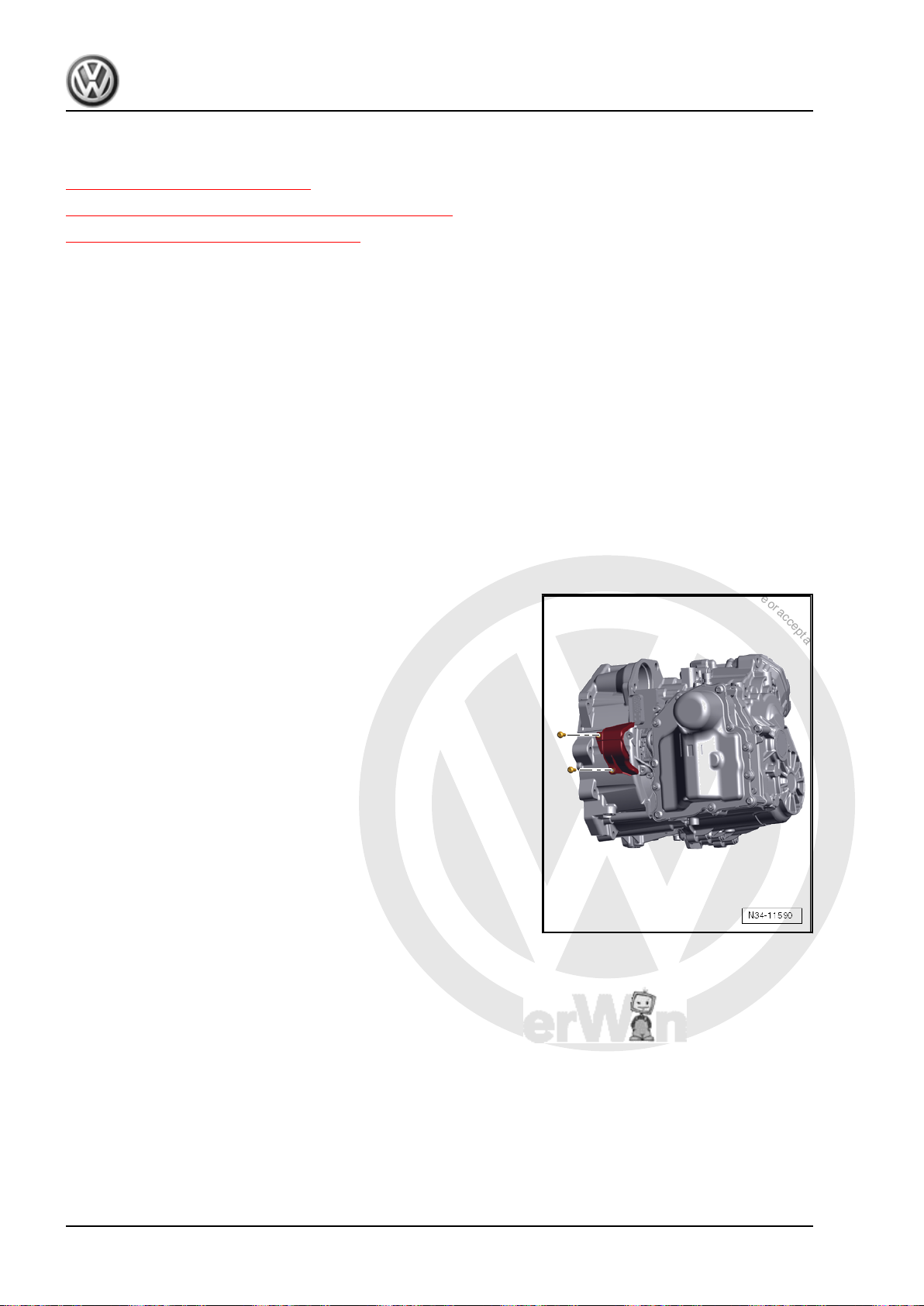
Some Vehicles Have A Cover Over the Engaging Levers.
The cover prevents dirt from getting in.
Bolt tightening specification: 8 Nm
6 Rep. Gr.00 - General, Technical Data
Page 11
P
r
o
t
e
c
t
e
d
b
y
c
o
p
y
r
i
g
h
t
.
C
o
p
y
i
n
g
f
o
r
p
r
i
v
a
t
e
o
r
c
o
m
m
e
r
c
i
a
l
p
u
r
p
o
s
e
s
,
i
n
p
a
r
t
o
r
i
n
w
h
o
l
e
,
i
s
n
o
t
p
e
r
m
i
t
t
e
d
u
n
l
e
s
s
a
u
t
h
o
r
i
s
e
d
b
y
V
o
l
k
s
w
a
g
e
n
A
G
.
V
o
l
k
s
w
a
g
e
n
A
G
d
o
e
s
n
o
t
g
u
a
r
a
n
t
e
e
o
r
a
c
c
e
p
t
a
n
y
l
i
a
b
i
l
i
t
y
w
i
t
h
r
e
s
p
e
c
t
t
o
t
h
e
c
o
r
r
e
c
t
n
e
s
s
o
f
i
n
f
o
r
m
a
t
i
o
n
i
n
t
h
i
s
d
o
c
u
m
e
n
t
.
C
o
p
y
r
i
g
h
t
b
y
V
o
l
k
s
w
a
g
e
n
A
G
.
Direct Shift Gearbox - Edition 01.2016
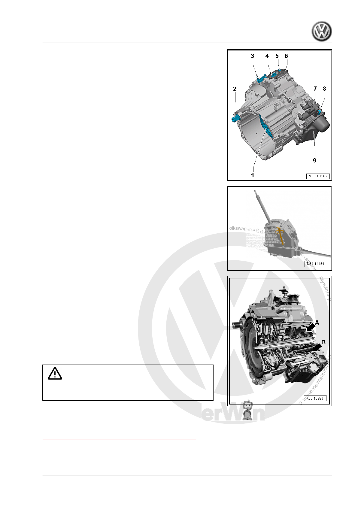
Transmission Assembly Overview
1 - Dual clutch
2 - Right Stub Shaft
3 - Cable Mounting Bracket
4 - Gearshift Lever
5 - Transmission ventilation cap
6 - Parking lock cover
7 - Valve block
8 - DSG Transmission Mechatronic - J743- Bleed Unit
9 - DSG Transmission Mechatronic - J743-
Selector Mechanism
In contrast to the automatic transmission, the selector lever po‐
sition is no longer transmitted mechanically to the transmission
via the selector lever cable and Multi-Function Transmission
Range. Selector lever positions and shifts are transmitted via a
separate control module in the selector mechanism to the trans‐
mission control module via the CAN-Bus. The shifter occurs
without a cable. The selector lever cable is mechanically brought
into the park brake in the selector lever position “P”.
Transmission Fluid
The 7-speed DSG® transmission has two separate, different fluid
systems. One for the transmission fluid -arrow A- and one for the
hydraulic fluid -arrow B-.
Only transmission fluids specific to the DSG® transmission 0CG
may be used. They are available as a replacement part. Using
other oils can lead to function problems or can even cause the
transmission to fail, for the specification. Refer to the Parts Cat‐
alog.
Do not mix any »additives« into the oil.
Do not re-use drained transmission fluid.
Caution
Be very careful when working with transmission fluid. Dispose
of drained transmission fluid correctly.
It is not possible to check the transmission fluid level in the trans‐
mission. The only way to adjust the transmission fluid level is to
replace the transmission fluid, for example, if the transmission is
leaking fluid. Refer to
⇒ “7.1 Transmission Fluid, Draining and Filling”, page 111 .
Jetta Hybrid 2013 ➤
3. Repair Information 7
Page 12

P
r
o
t
e
c
t
e
d
b
y
c
o
p
y
r
i
g
h
t
.
C
o
p
y
i
n
g
f
o
r
p
r
i
v
a
t
e
o
r
c
o
m
m
e
r
c
i
a
l
p
u
r
p
o
s
e
s
,
i
n
p
a
r
t
o
r
i
n
w
h
o
l
e
,
i
s
n
o
t
p
e
r
m
i
t
t
e
d
u
n
l
e
s
s
a
u
t
h
o
r
i
s
e
d
b
y
V
o
l
k
s
w
a
g
e
n
A
G
.
V
o
l
k
s
w
a
g
e
n
A
G
d
o
e
s
n
o
t
g
u
a
r
a
n
t
e
e
o
r
a
c
c
e
p
t
a
n
y
l
i
a
b
i
l
i
t
y
w
i
t
h
r
e
s
p
e
c
t
t
o
t
h
e
c
o
r
r
e
c
t
n
e
s
s
o
f
i
n
f
o
r
m
a
t
i
o
n
i
n
t
h
i
s
d
o
c
u
m
e
n
t
.
C
o
p
y
r
i
g
h
t
b
y
V
o
l
k
s
w
a
g
e
n
A
G
.
Jetta Hybrid 2013 ➤
Direct Shift Gearbox - Edition 01.2016
3.2 Guidelines for Clean Working Condi‐
tions
♦ Always clean connection places and surrounding areas with
engine or brake cleaner before loosening and dry cleaned pla‐
ces.
♦ Clean the transmission and transmission components using
for example Cleaning Solution - D 009 401 04- .
♦ Use lint-free towels.
♦ Seal all open lines and connections immediately with new
plugs from the Repair Kit - 5C0 998 152- . Refer to the Parts
Catalog.
♦ Place removed parts on a clean surface and cover them. Use
foil and paper. Use a lint-free cloth.
♦ Carefully cover or plug unpacked components if repairs can‐
not be performed immediately.
♦ Only install clean components: Remove the replacement parts
from their packaging just prior to installing them.
♦ Protect the disconnected connectors from dirt and moisture
and only connect when they are dry.
♦ Make sure no dirt can get into the transmission when it is open.
♦ Do not run the engine when the cover is removed from the
transmission or when there is no transmission fluid in the
transmission. Do not tow the vehicle.
♦ Cover all opened components carefully if it necessary to per‐
form a repair.
3.3 General Repair Information
♦ Carefulness, cleanliness and the correct tools are required for
transmission repairs to be successful. The usual basic safety
precautions also, naturally apply when carrying out vehicle re‐
pairs.
♦ Some general repair information that applies to several pro‐
cedures throughout this manual is summarized here. They
apply to this repair manual.
Guided Fault Finding, On Board Diagnostics (OBD) and Test In‐
struments
♦ Before servicing the transmission, determine as best as pos‐
sible the cause of the fault using the Vehicle Diagnostic Tester
in Guided Fault Finding , Vehicle Self-Diagnosis and
Test Instruments
The Guided Functions button and the Guided Fault Find-
ing button offer various functions. Refer to
⇒ “3.3.1 Working with Tester”, page 10 .
Special Tools and Equipment
.
For a complete list of special tools used in the Repair Manual.
Refer to Workshop Equipment and Special Tools.
Transmission
♦ Do not run engine or tow the vehicle when the oil pan is re‐
moved or when there is no transmission fluid.
♦ Always clean the connection locations and the area around
them before loosening.
8 Rep. Gr.00 - General, Technical Data
Page 13
P
r
o
t
e
c
t
e
d
b
y
c
o
p
y
r
i
g
h
t
.
C
o
p
y
i
n
g
f
o
r
p
r
i
v
a
t
e
o
r
c
o
m
m
e
r
c
i
a
l
p
u
r
p
o
s
e
s
,
i
n
p
a
r
t
o
r
i
n
w
h
o
l
e
,
i
s
n
o
t
p
e
r
m
i
t
t
e
d
u
n
l
e
s
s
a
u
t
h
o
r
i
s
e
d
b
y
V
o
l
k
s
w
a
g
e
n
A
G
.
V
o
l
k
s
w
a
g
e
n
A
G
d
o
e
s
n
o
t
g
u
a
r
a
n
t
e
e
o
r
a
c
c
e
p
t
a
n
y
l
i
a
b
i
l
i
t
y
w
i
t
h
r
e
s
p
e
c
t
t
o
t
h
e
c
o
r
r
e
c
t
n
e
s
s
o
f
i
n
f
o
r
m
a
t
i
o
n
i
n
t
h
i
s
d
o
c
u
m
e
n
t
.
C
o
p
y
r
i
g
h
t
b
y
V
o
l
k
s
w
a
g
e
n
A
G
.
Direct Shift Gearbox - Edition 01.2016
♦ During installation, make sure that the alignment bushings are
fitted correctly.
O-Rings, Gaskets, Seals
♦ O-rings, gaskets and seals must be replaced.
♦ Seals are also called shaft seals.
♦ After removing gaskets, examine contact surface on housing/
shaft for burr resulting from removal or for other signs of dam‐
age.
♦ Clean the housing separating surface thoroughly before as‐
sembling.
♦ Lightly coat the seals with ATF along outer circumference and
along the sealing lip.
♦ Coat O-rings with transmission fluid before inserting to prevent
crushing rings during installation.
♦ Do not use any other lubricants in the gear oil area. Otherwise
there is a danger of malfunction of the transmission hydraulics.
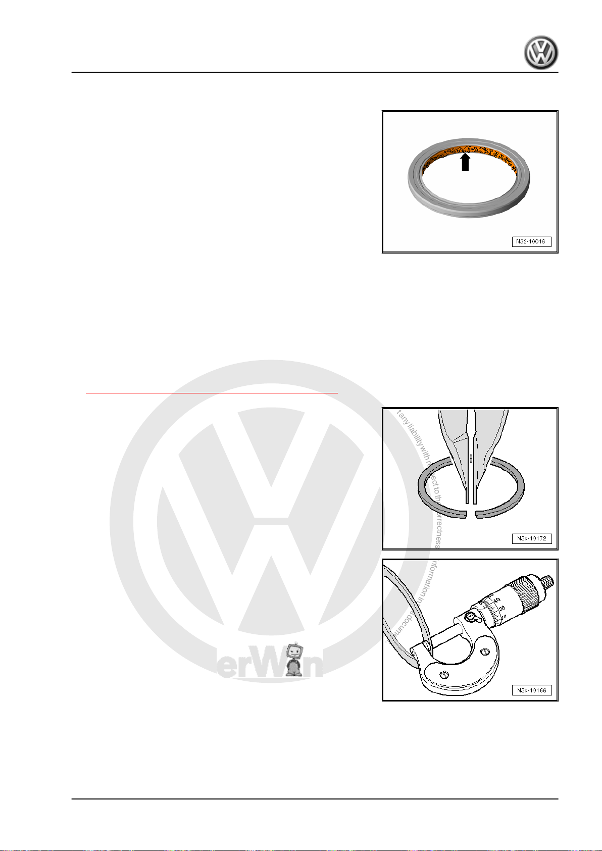
♦ The open side of the seals point toward the fluid to be sealed
in.
♦ When installing the new shaft seals, make sure the sealing lip
does not run on the same point as the sealing lip of the old
seal (use insertion depth tolerances).
♦ Follow the guidelines for clean working conditions. Refer to
⇒ “3.2 Guidelines for Clean Working Conditions”, page 8 .
Fasteners
♦ Do not overstretch the circlips.
♦ Replace damaged or stretched circlips.
♦ The circlips must fit completely inside the groove.
Adjusting Shims
♦ Measure the shims at several locations with a micrometer cal‐
iper. It is possible to measure the necessary shim thickness
by the different tolerances.
♦ Check for burrs and damage.
♦ Only install perfect shims.
Jetta Hybrid 2013 ➤
3. Repair Information 9
Page 14
P
r
o
t
e
c
t
e
d
b
y
c
o
p
y
r
i
g
h
t
.
C
o
p
y
i
n
g
f
o
r
p
r
i
v
a
t
e
o
r
c
o
m
m
e
r
c
i
a
l
p
u
r
p
o
s
e
s
,
i
n
p
a
r
t
o
r
i
n
w
h
o
l
e
,
i
s
n
o
t
p
e
r
m
i
t
t
e
d
u
n
l
e
s
s
a
u
t
h
o
r
i
s
e
d
b
y
V
o
l
k
s
w
a
g
e
n
A
G
.
V
o
l
k
s
w
a
g
e
n
A
G
d
o
e
s
n
o
t
g
u
a
r
a
n
t
e
e
o
r
a
c
c
e
p
t
a
n
y
l
i
a
b
i
l
i
t
y
w
i
t
h
r
e
s
p
e
c
t
t
o
t
h
e
c
o
r
r
e
c
t
n
e
s
s
o
f
i
n
f
o
r
m
a
t
i
o
n
i
n
t
h
i
s
d
o
c
u
m
e
n
t
.
C
o
p
y
r
i
g
h
t
b
y
V
o
l
k
s
w
a
g
e
n
A
G
.
Jetta Hybrid 2013 ➤
Direct Shift Gearbox - Edition 01.2016
Bolts and Nuts
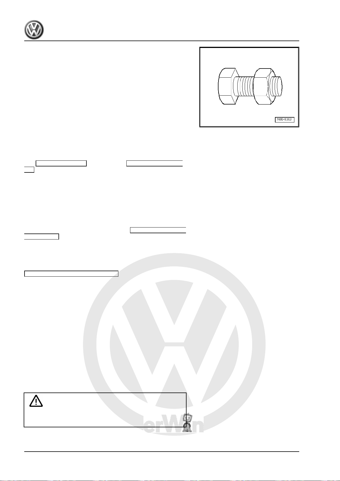
♦ Loosen the bolts opposite the tightening sequence.
♦ Nuts and bolts which secure covers and housings should be
loosened and tightened diagonally and in steps if no tightening
sequence is specified.
♦ Replace the self-locking nuts.
♦ Use a wire brush to clean the threads of bolts that were
screwed in with locking compound. Install the bolts with Lock‐
ing Fluid - AMV 185 101 A1- .
♦ The tightening specifications stated apply to non-oiled nuts
and bolts.
3.3.1 Working with Tester
• Use only Volkswagen Vehicle Diagnostic Testers .
The Guided Functions button and the Guided Fault Find-
ing button offer various functions. The 3 most important functions
are:
♦ Adapting installation information
♦ Reading measurements for mandatory reporting
♦ Performing basic measurement
Adapting Installation Information
The Mechatronic recognizes other control modules in the vehicle
by signals from the Data bus. Pressing the Adapt Installation
Information button tells the Mechatronic to forget all communi‐
cation partners.
All active partners are recognized the next time the ignition is
turned on.
Faults cannot be »created« with this function. Always use the
Adapt Installation Information after the following tasks:
♦ After installing a gearshift mechanism.
♦ After a different control module is installed, for example, en‐
gine, ABS or Gateway.
♦ After working on the steering wheel paddle.
Reading Measurements for Mandatory Reporting
It is necessary to upload the measurements before contacting the
Technical Service Center.
Save the measurements in the diagnostic log so that all the nec‐
essary transmission data is available for analyzing the faults.
Performing Basic Measurement.
This is how the Mechatronic learns the important settings. Also
important adjustments are learned new or reset to the preprog‐
rammed points. Among others, these are the synchronizing points
and the corner points for the engaging lever and the gear selector.
WARNING
Do not perform a basic measurement without cause or without
being requested.
10 Rep. Gr.00 - General, Technical Data
Page 15

P
r
o
t
e
c
t
e
d
b
y
c
o
p
y
r
i
g
h
t
.
C
o
p
y
i
n
g
f
o
r
p
r
i
v
a
t
e
o
r
c
o
m
m
e
r
c
i
a
l
p
u
r
p
o
s
e
s
,
i
n
p
a
r
t
o
r
i
n
w
h
o
l
e
,
i
s
n
o
t
p
e
r
m
i
t
t
e
d
u
n
l
e
s
s
a
u
t
h
o
r
i
s
e
d
b
y
V
o
l
k
s
w
a
g
e
n
A
G
.
V
o
l
k
s
w
a
g
e
n
A
G
d
o
e
s
n
o
t
g
u
a
r
a
n
t
e
e
o
r
a
c
c
e
p
t
a
n
y
l
i
a
b
i
l
i
t
y
w
i
t
h
r
e
s
p
e
c
t
t
o
t
h
e
c
o
r
r
e
c
t
n
e
s
s
o
f
i
n
f
o
r
m
a
t
i
o
n
i
n
t
h
i
s
d
o
c
u
m
e
n
t
.
C
o
p
y
r
i
g
h
t
b
y
V
o
l
k
s
w
a
g
e
n
A
G
.
– Press the J743 Perform Mechatronic Basic Measure-
ment screen button only:
♦ If the “Guided Fault Finding” requests it
♦ After a fault stored in the Diagnostic Trouble Code (DTC)
memory was corrected
♦ After a dual clutch was installed
♦ Or after a Mechatronic was installed
Jetta Hybrid 2013 ➤
Direct Shift Gearbox - Edition 01.2016
3. Repair Information 11
Page 16
P
r
o
t
e
c
t
e
d
b
y
c
o
p
y
r
i
g
h
t
.
C
o
p
y
i
n
g
f
o
r
p
r
i
v
a
t
e
o
r
c
o
m
m
e
r
c
i
a
l
p
u
r
p
o
s
e
s
,
i
n
p
a
r
t
o
r
i
n
w
h
o
l
e
,
i
s
n
o
t
p
e
r
m
i
t
t
e
d
u
n
l
e
s
s
a
u
t
h
o
r
i
s
e
d
b
y
V
o
l
k
s
w
a
g
e
n
A
G
.
V
o
l
k
s
w
a
g
e
n
A
G
d
o
e
s
n
o
t
g
u
a
r
a
n
t
e
e
o
r
a
c
c
e
p
t
a
n
y
l
i
a
b
i
l
i
t
y
w
i
t
h
r
e
s
p
e
c
t
t
o
t
h
e
c
o
r
r
e
c
t
n
e
s
s
o
f
i
n
f
o
r
m
a
t
i
o
n
i
n
t
h
i
s
d
o
c
u
m
e
n
t
.
C
o
p
y
r
i
g
h
t
b
y
V
o
l
k
s
w
a
g
e
n
A
G
.
Jetta Hybrid 2013 ➤
Direct Shift Gearbox - Edition 01.2016
4 Technical Data
⇒ “4.1 Transmission/Engine Allocation”, page 12
⇒ “4.2 Gear Ratio Calculation”, page 12
⇒ “4.3 Capacities”, page 13
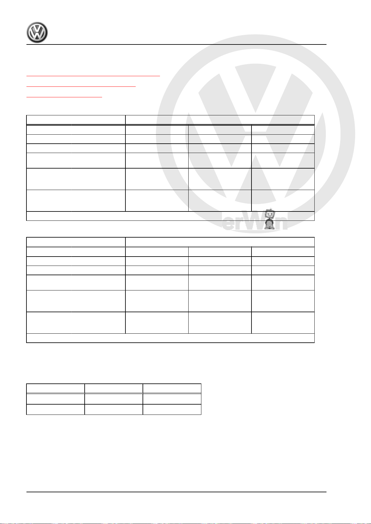
4.1 Transmission/Engine Allocation
DSG Transmission 0CG
Transmission Codes NDR PLC PMY
Allocation Type
Gear Ratios Final drive I
Z2: Z
1
Z2: Z
1
Use the transmission code when ordering replacement parts for a repair. Refer to the Parts Catalog.
Engine
for 1st to 4th gear
Final drive II
for 5th gear and
6th gear
Final drive III
for 7th gear and re‐
verse gear
Jetta from MY 2011 Jetta from MY 2011 Jetta from MY 2011
1.4L TSI - 110 kW 1.4L TSI - 110 kW 1.4L TSI - 110 kW
71 : 16 = 4.438 71 : 16 = 4.438 71 : 16 = 4.438
71 : 22 = 3.227 71 : 22 = 3.227 71 : 22 = 3.227
71 : 17 = 4.176 71 : 17 = 4.176 71 : 17 = 4.176
DSG Transmission 0CG
Transmission Codes PWK PZV QHT
Allocation Type
Engine
Gear Ratios Final drive I
Jetta from MY 2011 Jetta from MY 2011 Jetta from MY 2011
1.4L TSI - 110 kW 1.4L TSI - 110 kW 1.4L TSI - 110 kW
71 : 16 = 4.438 71 : 16 = 4.438 71 : 16 = 4.438
for 1st to 4th gear
Z2: Z
1
Final drive II
71 : 22 = 3.227 71 : 22 = 3.227 71 : 22 = 3.227
for 5th gear and
6th gear
Z2: Z
1
Final drive III
71 : 17 = 4.176 71 : 17 = 4.176 71 : 17 = 4.176
for 7th gear and re‐
verse gear
Use the transmission code when ordering replacement parts for a repair. Refer to the Parts Catalog.
4.2 Gear Ratio Calculation
Example:
7. Gear Final Drive
Drive gear ZG1 = 49 ZA1 = 17
Driven gear ZG2 = 32 ZA2 = 71
i = Z2 : Z1 (Z1 = Number of teeth on the drive gear, Z2 = number
of teeth on the driven gear)
iG = gear ratio = ZG2 : ZG1 = 32 : 49 = 0.653
iA = axle ratio = ZA2 : ZA1 = 71 : 17 = 4.176
i
= total ratio= iG x iA = 0.653 x 4.176 = 2.730
total
12 Rep. Gr.00 - General, Technical Data
Page 17
P
r
o
t
e
c
t
e
d
b
y
c
o
p
y
r
i
g
h
t
.
C
o
p
y
i
n
g
f
o
r
p
r
i
v
a
t
e
o
r
c
o
m
m
e
r
c
i
a
l
p
u
r
p
o
s
e
s
,
i
n
p
a
r
t
o
r
i
n
w
h
o
l
e
,
i
s
n
o
t
p
e
r
m
i
t
t
e
d
u
n
l
e
s
s
a
u
t
h
o
r
i
s
e
d
b
y
V
o
l
k
s
w
a
g
e
n
A
G
.
V
o
l
k
s
w
a
g
e
n
A
G
d
o
e
s
n
o
t
g
u
a
r
a
n
t
e
e
o
r
a
c
c
e
p
t
a
n
y
l
i
a
b
i
l
i
t
y
w
i
t
h
r
e
s
p
e
c
t
t
o
t
h
e
c
o
r
r
e
c
t
n
e
s
s
o
f
i
n
f
o
r
m
a
t
i
o
n
i
n
t
h
i
s
d
o
c
u
m
e
n
t
.
C
o
p
y
r
i
g
h
t
b
y
V
o
l
k
s
w
a
g
e
n
A
G
.
Direct Shift Gearbox - Edition 01.2016
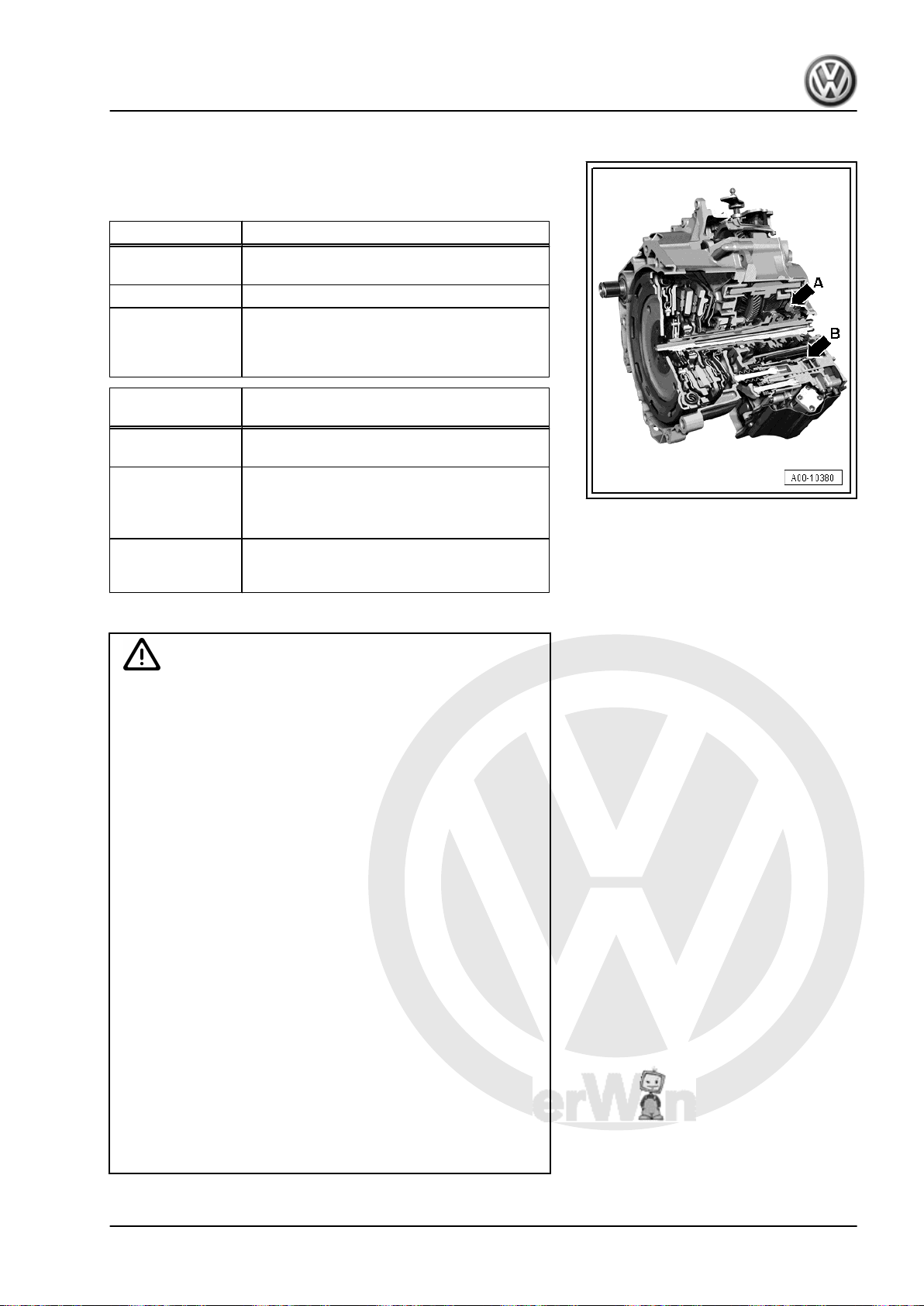
4.3 Capacities
The 7-speed DSG® transmission has two separate, different fluid
systems. One for the transmission fluid -arrow A- and one for the
hydraulic fluid -arrow B-.
Capacities Transmission Fluid
Initial filling Refer to ⇒ Fluid Capacity Tables; Rep. Gr.
03
Change No change required
Lubricant Transmission fluid for DSG transmission
0CG
For the part number. Refer to the Parts Cat‐
alog.
Capacities Hydraulic Fluid in DSG Transmission Me‐
chatronic - J743-
Initial filling Refer to ⇒ Fluid Capacity Tables; Rep. Gr.
03
Change Change not possible
Checking the hydraulic fluid level for the
DSG Transmission Mechatronic - J743- is
not possible 1).
Lubricant Hydraulic oil
For the part number. Refer to the Parts Cat‐
alog.
Jetta Hybrid 2013 ➤
1)
It is possible to fill hydraulic fluid via the Mechatronic vent.
Caution
Danger of causing damage to the transmission.
♦ Use only the transmission fluid specifically for the 7-speed
DSG transmission 0CG. It is available as a replacement
part. Refer to the Parts Catalog.
♦ Using other fluids can cause malfunctions or transmission
failure.
♦ Checking the hydraulic fluid level in the DSG Transmis‐
sion Mechatronic - J743- is not possible. The vent on the
DSG Transmission Mechatronic - J743- must be sealed
tight before performing any assembly work.
♦ Hydraulic fluid that has leaked out of the DSG Transmis‐
sion Mechatronic - J743- may not refilled.
♦ Seal off all openings with new plugs from the Repair Kit -
5C0 998 152- whenever the hydraulic pipe between the
valve block on the DSG Transmission Mechatronic - J743and the connection for the decoupler for the Electro-Drive
Drive Motor - V141- is removed. After installing the hy‐
draulic pipe, add hydraulic fluid via the vent for the Me‐
chatronic , if necessary. For the correct hydraulic fluid,
sealing plugs and disposable syringe from the Repair Kit
- 5C0 998 152- . Refer to the Parts Catalog.
♦ If transmission fluid has leaked out, then it is necessary to
perform a transmission fluid replacement. It is not possible
to check the fluid level.
♦ Under filling or overfilling both fluid systems will impair the
function of the transmission.
4. Technical Data 13
Page 18
P
r
o
t
e
c
t
e
d
b
y
c
o
p
y
r
i
g
h
t
.
C
o
p
y
i
n
g
f
o
r
p
r
i
v
a
t
e
o
r
c
o
m
m
e
r
c
i
a
l
p
u
r
p
o
s
e
s
,
i
n
p
a
r
t
o
r
i
n
w
h
o
l
e
,
i
s
n
o
t
p
e
r
m
i
t
t
e
d
u
n
l
e
s
s
a
u
t
h
o
r
i
s
e
d
b
y
V
o
l
k
s
w
a
g
e
n
A
G
.
V
o
l
k
s
w
a
g
e
n
A
G
d
o
e
s
n
o
t
g
u
a
r
a
n
t
e
e
o
r
a
c
c
e
p
t
a
n
y
l
i
a
b
i
l
i
t
y
w
i
t
h
r
e
s
p
e
c
t
t
o
t
h
e
c
o
r
r
e
c
t
n
e
s
s
o
f
i
n
f
o
r
m
a
t
i
o
n
i
n
t
h
i
s
d
o
c
u
m
e
n
t
.
C
o
p
y
r
i
g
h
t
b
y
V
o
l
k
s
w
a
g
e
n
A
G
.
Jetta Hybrid 2013 ➤
Direct Shift Gearbox - Edition 01.2016
5 Overview - Powertrain
⇒ “5.1 Overview - Powertrain, Front Wheel Drive”, page 14
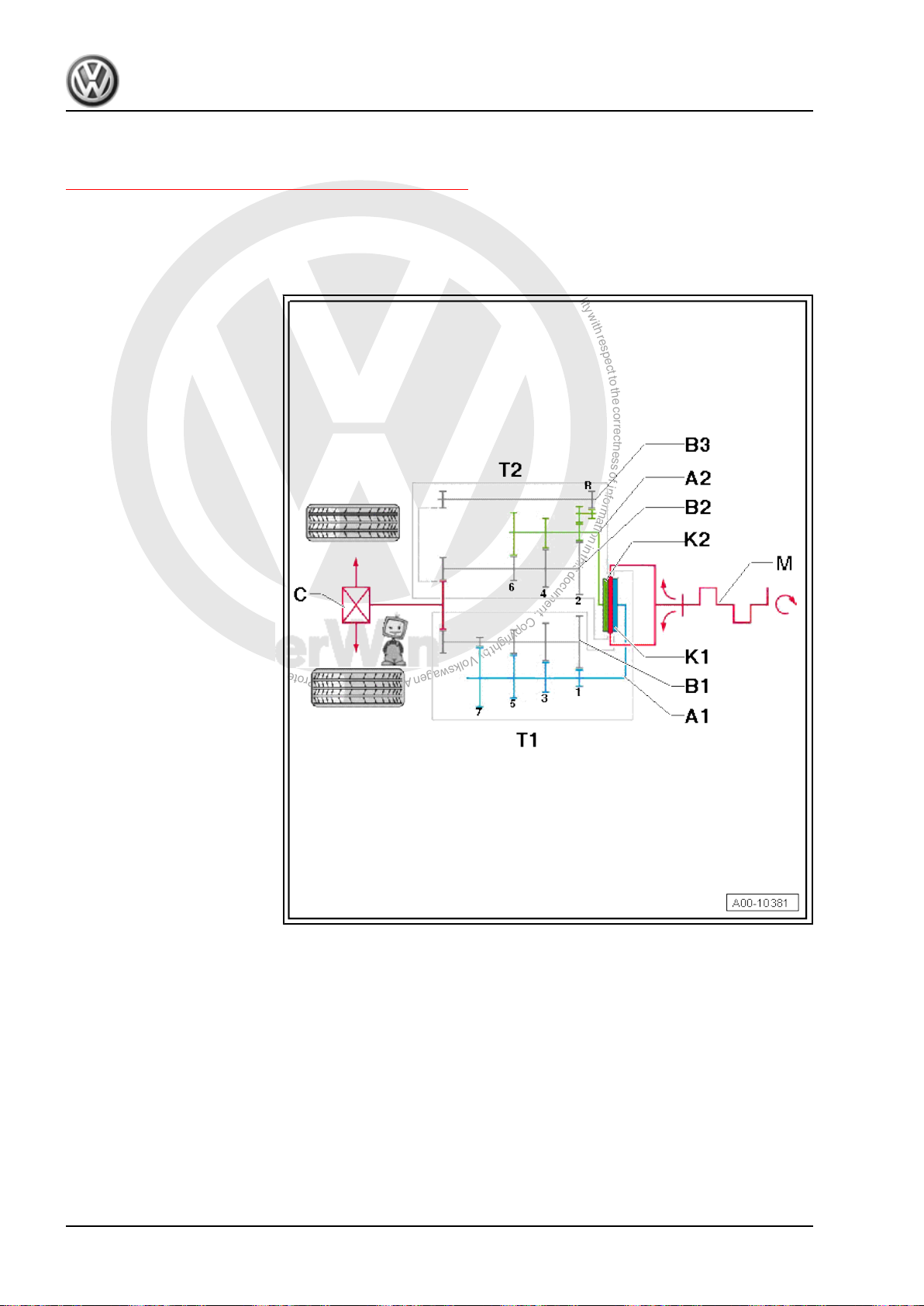
5.1 Overview - Powertrain, Front Wheel Drive
The 7-speed DSG transmission 0CG has 5 shafts. Two input
shafts and three output shafts.
A1 - Input Shaft 1
A2 - Input Shaft 2
B1 - Output Shaft 1
B2 - Output Shaft 2
B3 - Output Shaft 3
C - Front Final Drive
K1 - Clutch 1
K2 - Clutch 2
M - Engine
T1 - Sub-Transmission 1
❑ With 1st, 3rd, 5th and
7th gears
T2 - Sub-Transmission 2
❑ With 2nd, 4th, 6th and
reverse gears
14 Rep. Gr.00 - General, Technical Data
Page 19
P
r
o
t
e
c
t
e
d
b
y
c
o
p
y
r
i
g
h
t
.
C
o
p
y
i
n
g
f
o
r
p
r
i
v
a
t
e
o
r
c
o
m
m
e
r
c
i
a
l
p
u
r
p
o
s
e
s
,
i
n
p
a
r
t
o
r
i
n
w
h
o
l
e
,
i
s
n
o
t
p
e
r
m
i
t
t
e
d
u
n
l
e
s
s
a
u
t
h
o
r
i
s
e
d
b
y
V
o
l
k
s
w
a
g
e
n
A
G
.
V
o
l
k
s
w
a
g
e
n
A
G
d
o
e
s
n
o
t
g
u
a
r
a
n
t
e
e
o
r
a
c
c
e
p
t
a
n
y
l
i
a
b
i
l
i
t
y
w
i
t
h
r
e
s
p
e
c
t
t
o
t
h
e
c
o
r
r
e
c
t
n
e
s
s
o
f
i
n
f
o
r
m
a
t
i
o
n
i
n
t
h
i
s
d
o
c
u
m
e
n
t
.
C
o
p
y
r
i
g
h
t
b
y
V
o
l
k
s
w
a
g
e
n
A
G
.
Jetta Hybrid 2013 ➤
Direct Shift Gearbox - Edition 01.2016
30 – Clutch
1 Clutch Mechanism
⇒ “1.1 Overview - Clutch Engaging Mechanism”, page 15
⇒ “1.2 Clutch Engaging Mechanism, Removing and Installing”,
page 16
⇒ “1.3 Clutch Engaging Mechanism, Adjusting”, page 19
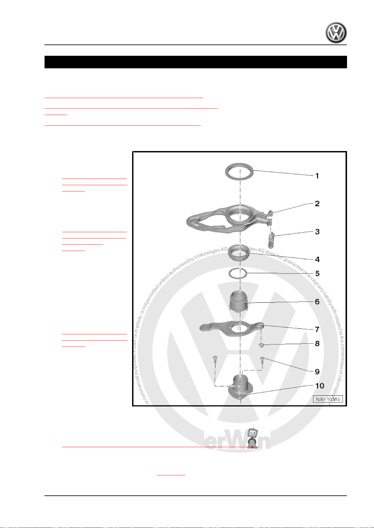
1.1 Overview - Clutch Engaging Mechanism
1 - Shim for “K 1”
❑ For determining thick‐
ness. Refer to
⇒ “1.3 Clutch Engaging
Mechanism, Adjusting”,
page 19 .
2 - Large Engaging Lever “K 1”
❑ With engaging bearing
❑ Removing and instal‐
ling. Refer to
⇒ “1.2 Clutch Engaging
Mechanism, Removing
and Installing”,
page 16 .
3 - Engaging Lever Support
❑ For the large engaging
lever “K 1”
❑ Cannot be replaced
4 - Small Engaging Bearing for
“K 2”
5 - Shim for “K 2”
❑ For determining thick‐
ness. Refer to
⇒ “1.3 Clutch Engaging
Mechanism, Adjusting”,
page 19 .
6 - Guide Sleeve Upper Sec‐
tion
❑ For the small engaging
lever “K 2”
❑ Is removed and installed
together with the small
engaging lever and the
guide sleeve lower sec‐
tion
7 - Small Engaging Lever for “K 2”
❑ Is removed and installed together with the guide sleeve upper section and lower section
❑ Removing and installing. Refer to
⇒ “1.2 Clutch Engaging Mechanism, Removing and Installing”, page 16 .
8 - Ball Stud
❑ For the small engaging lever “K 2”
❑ Removing and installing. Refer to ⇒ page 20 .
1. Clutch Mechanism 15
Page 20
P
r
o
t
e
c
t
e
d
b
y
c
o
p
y
r
i
g
h
t
.
C
o
p
y
i
n
g
f
o
r
p
r
i
v
a
t
e
o
r
c
o
m
m
e
r
c
i
a
l
p
u
r
p
o
s
e
s
,
i
n
p
a
r
t
o
r
i
n
w
h
o
l
e
,
i
s
n
o
t
p
e
r
m
i
t
t
e
d
u
n
l
e
s
s
a
u
t
h
o
r
i
s
e
d
b
y
V
o
l
k
s
w
a
g
e
n
A
G
.
V
o
l
k
s
w
a
g
e
n
A
G
d
o
e
s
n
o
t
g
u
a
r
a
n
t
e
e
o
r
a
c
c
e
p
t
a
n
y
l
i
a
b
i
l
i
t
y
w
i
t
h
r
e
s
p
e
c
t
t
o
t
h
e
c
o
r
r
e
c
t
n
e
s
s
o
f
i
n
f
o
r
m
a
t
i
o
n
i
n
t
h
i
s
d
o
c
u
m
e
n
t
.
C
o
p
y
r
i
g
h
t
b
y
V
o
l
k
s
w
a
g
e
n
A
G
.
Jetta Hybrid 2013 ➤
Direct Shift Gearbox - Edition 01.2016
9 - Bolt
❑ 8 Nm +90° turn
❑ Replace after removing
10 - Guide Sleeve Lower Section
❑ For the small engaging lever “K 2”
❑ Is removed and installed together with the small engaging lever and the guide sleeve upper section
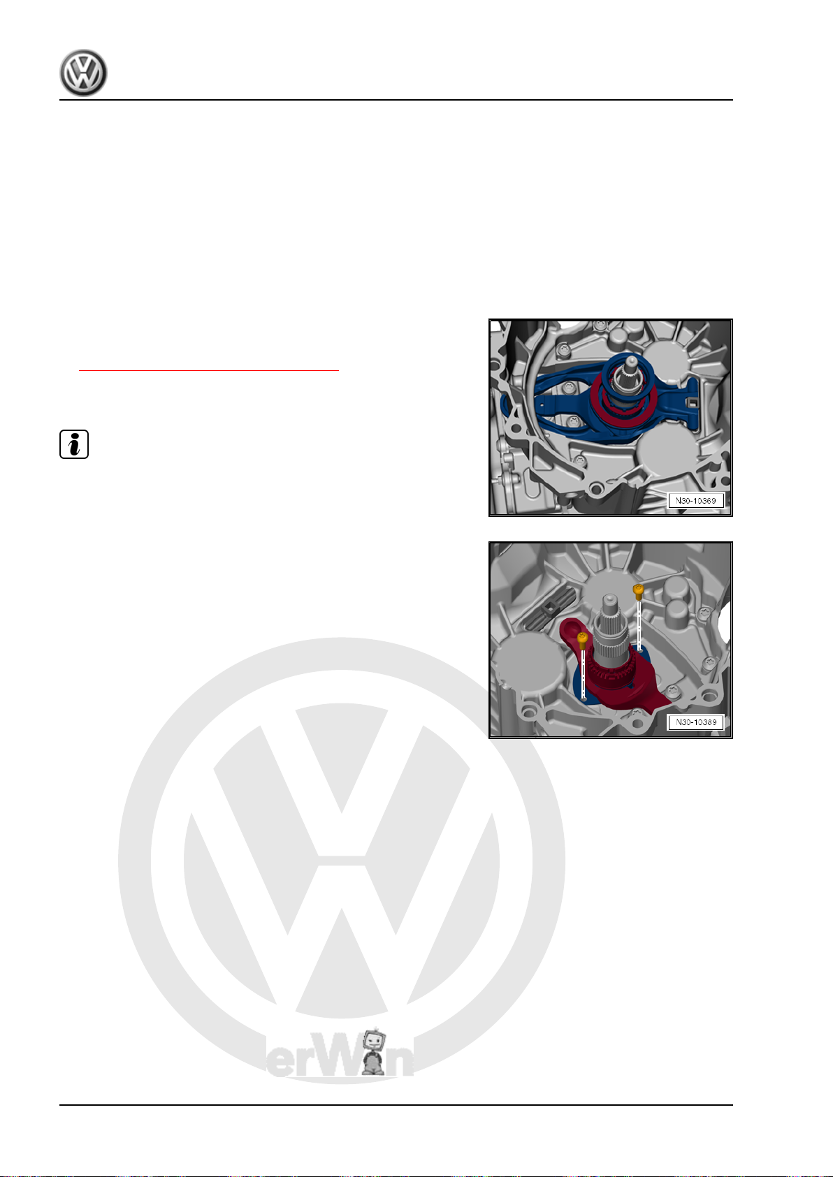
1.2 Clutch Engaging Mechanism, Remov‐
ing and Installing
Removing
• The dual clutch is removed. Refer to
⇒ “2.2 DSG® Clutch, Removing”, page 33 .
– Remove the large engaging lever with the small engaging
bearing.
Note
The guide sleeve upper section cannot be removed or installed
separately. It is always removed and installed together with the
guide sleeve lower section and the small engaging lever.
– Remove the bolts and the small engaging lever with the guide
sleeve upper and lower sections.
16 Rep. Gr.30 - Clutch
Page 21
P
r
o
t
e
c
t
e
d
b
y
c
o
p
y
r
i
g
h
t
.
C
o
p
y
i
n
g
f
o
r
p
r
i
v
a
t
e
o
r
c
o
m
m
e
r
c
i
a
l
p
u
r
p
o
s
e
s
,
i
n
p
a
r
t
o
r
i
n
w
h
o
l
e
,
i
s
n
o
t
p
e
r
m
i
t
t
e
d
u
n
l
e
s
s
a
u
t
h
o
r
i
s
e
d
b
y
V
o
l
k
s
w
a
g
e
n
A
G
.
V
o
l
k
s
w
a
g
e
n
A
G
d
o
e
s
n
o
t
g
u
a
r
a
n
t
e
e
o
r
a
c
c
e
p
t
a
n
y
l
i
a
b
i
l
i
t
y
w
i
t
h
r
e
s
p
e
c
t
t
o
t
h
e
c
o
r
r
e
c
t
n
e
s
s
o
f
i
n
f
o
r
m
a
t
i
o
n
i
n
t
h
i
s
d
o
c
u
m
e
n
t
.
C
o
p
y
r
i
g
h
t
b
y
V
o
l
k
s
w
a
g
e
n
A
G
.
Replace the ball stud -2- only if it is worn down. Refer to
⇒ page 20 .
WARNING
The hinge -1- cannot be removed.
Jetta Hybrid 2013 ➤
Direct Shift Gearbox - Edition 01.2016
Installing
Install in reverse order of removal. Note the following:
WARNING
It is necessary to adjust the position of the “K 1” and “K 2” en‐
gaging bearing after performing the following:
The hinge cannot be removed.
It is necessary to adjust the position of the “K 1 and K 2” en‐
gaging bearings first if one of the above mentioned procedures
was performed. Refer to
⇒ “1.3 Clutch Engaging Mechanism, Adjusting”, page 19 .
It is not necessary to perform any adjustment if all the mentioned
components are removed and installed again individually.
♦ The dual clutch was replaced.
♦ The engaging levers were replaced.
♦ The ball stud for the “K 2” engaging lever was replaced.
♦ The engaging bearings were replaced.
Note
• The engaging lever support -1- and ball stud -2- are installed.
• Replace the ball stud -2- only if it is worn down. Refer to
⇒ page 20 .
1. Clutch Mechanism 17
Page 22
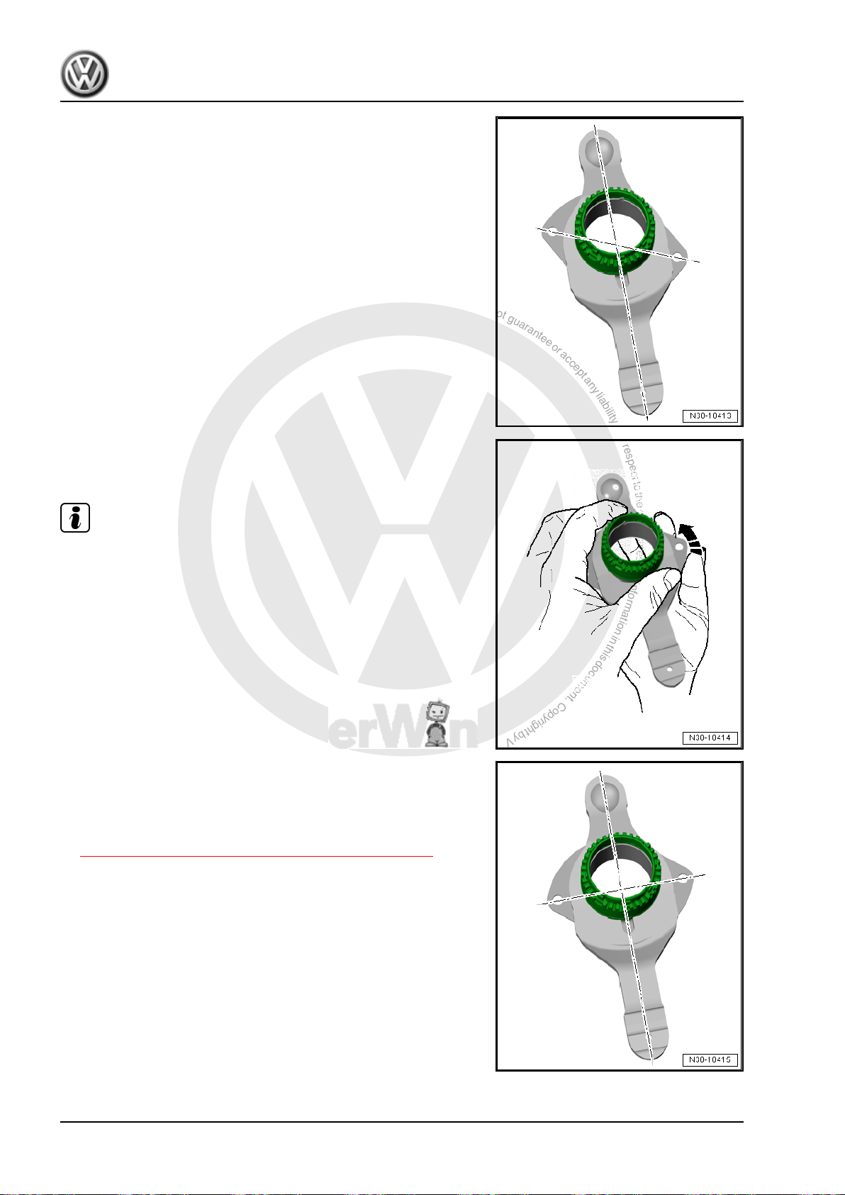
P
r
o
t
e
c
t
e
d
b
y
c
o
p
y
r
i
g
h
t
.
C
o
p
y
i
n
g
f
o
r
p
r
i
v
a
t
e
o
r
c
o
m
m
e
r
c
i
a
l
p
u
r
p
o
s
e
s
,
i
n
p
a
r
t
o
r
i
n
w
h
o
l
e
,
i
s
n
o
t
p
e
r
m
i
t
t
e
d
u
n
l
e
s
s
a
u
t
h
o
r
i
s
e
d
b
y
V
o
l
k
s
w
a
g
e
n
A
G
.
V
o
l
k
s
w
a
g
e
n
A
G
d
o
e
s
n
o
t
g
u
a
r
a
n
t
e
e
o
r
a
c
c
e
p
t
a
n
y
l
i
a
b
i
l
i
t
y
w
i
t
h
r
e
s
p
e
c
t
t
o
t
h
e
c
o
r
r
e
c
t
n
e
s
s
o
f
i
n
f
o
r
m
a
t
i
o
n
i
n
t
h
i
s
d
o
c
u
m
e
n
t
.
C
o
p
y
r
i
g
h
t
b
y
V
o
l
k
s
w
a
g
e
n
A
G
.
Jetta Hybrid 2013 ➤
Direct Shift Gearbox - Edition 01.2016
Note the Following When Installing A New Engaging Lever »K 2«:
A new engaging lever »K 2« with guide sleeve upper and lower
sections are in their transportation position when they are deliv‐
ered -illustration-. It is necessary to first move them into their
installation position before installing them.
Bringing the engaging lever »K 2« into the installed position as
follows:
– Hold the guide sleeve upper section with one hand. Turn the
guide sleeve lower section in direction of -arrow- with the other
hand until the sleeve moves freely.
Note
Hold both parts securely because a lot of force is needed to turn
the guide sleeve lower section.
In the installed position, the holes in the guide sleeve lower sec‐
tion are at a right angle to the engaging lever and the sleeve can
be moved freely.
– It is necessary to adjust the position of the engaging bearing
“K 1” and “K 2” when installing a new engaging lever. Refer to
⇒ “1.3 Clutch Engaging Mechanism, Adjusting”, page 19 .
18 Rep. Gr.30 - Clutch
Page 23
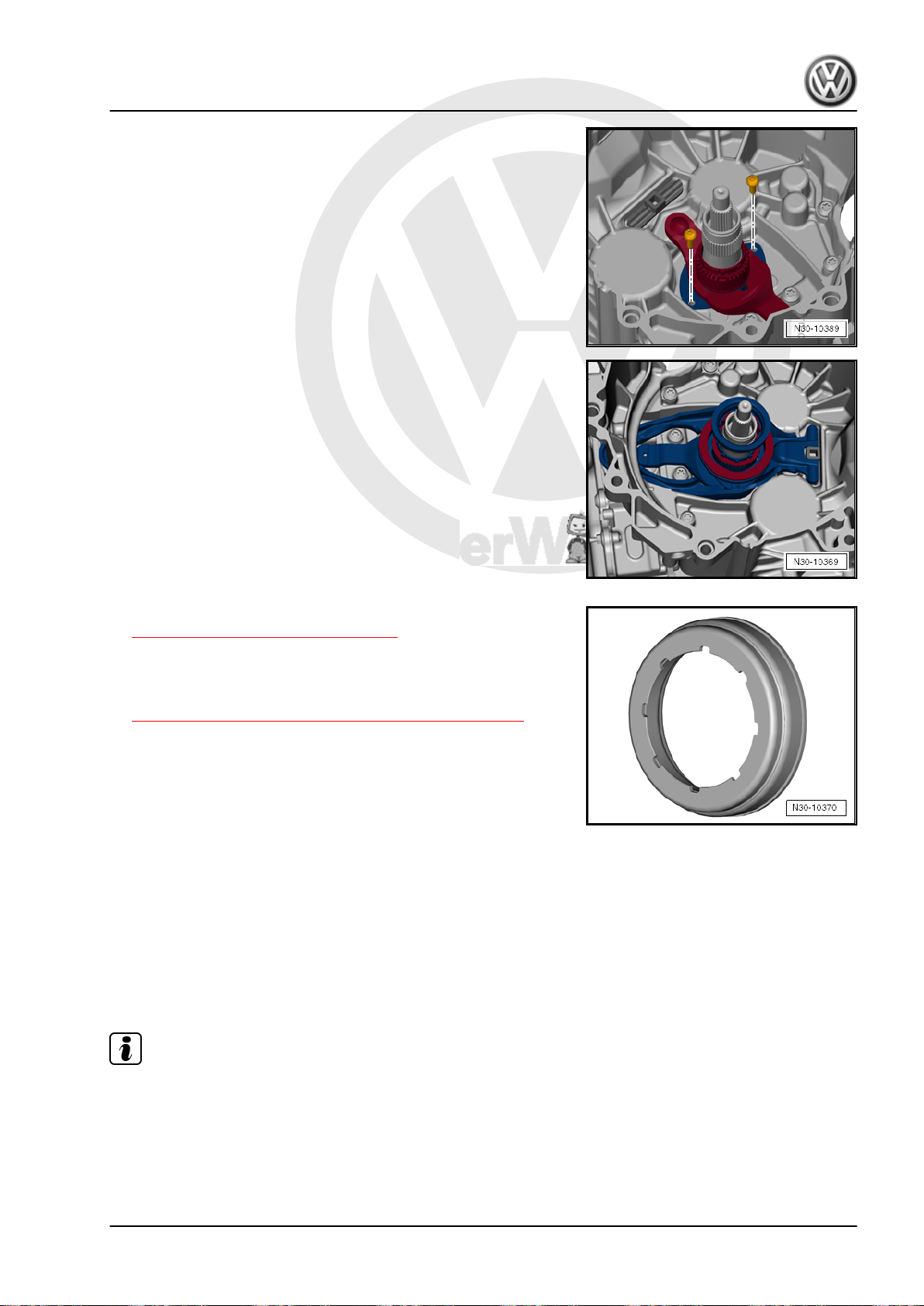
P
r
o
t
e
c
t
e
d
b
y
c
o
p
y
r
i
g
h
t
.
C
o
p
y
i
n
g
f
o
r
p
r
i
v
a
t
e
o
r
c
o
m
m
e
r
c
i
a
l
p
u
r
p
o
s
e
s
,
i
n
p
a
r
t
o
r
i
n
w
h
o
l
e
,
i
s
n
o
t
p
e
r
m
i
t
t
e
d
u
n
l
e
s
s
a
u
t
h
o
r
i
s
e
d
b
y
V
o
l
k
s
w
a
g
e
n
A
G
.
V
o
l
k
s
w
a
g
e
n
A
G
d
o
e
s
n
o
t
g
u
a
r
a
n
t
e
e
o
r
a
c
c
e
p
t
a
n
y
l
i
a
b
i
l
i
t
y
w
i
t
h
r
e
s
p
e
c
t
t
o
t
h
e
c
o
r
r
e
c
t
n
e
s
s
o
f
i
n
f
o
r
m
a
t
i
o
n
i
n
t
h
i
s
d
o
c
u
m
e
n
t
.
C
o
p
y
r
i
g
h
t
b
y
V
o
l
k
s
w
a
g
e
n
A
G
.
Continuation for All
– Install the small engaging lever with the upper and lower sec‐
tions of the guide sleeve. Install new bolts and tighten them.
– Install the large engaging lever with the selected shims for “K
1” and “K 2” and with the small engaging bearing.
• The large shim in the large engaging bearing with the halfround side facing down.
• The small shim belongs under the small engaging bearing. In‐
stall the shim first.
• The shim and the small engaging bearing fit only in one posi‐
tion due to the 8 grooves.
– Turn and make sure the parts are installed correctly and fit
correctly in the grooves.
– Make sure both engaging levers fit correctly.
Direct Shift Gearbox - Edition 01.2016
– Install the dual clutch. Refer to
⇒ “2.3 Dual Clutch, Installing”, page 37 .
Tightening Specifications
♦ For the guide sleeve lower section together with the small en‐
gaging lever to transmission housing. Refer to
⇒ “1.1 Overview - Clutch Engaging Mechanism”, page 15 .
Jetta Hybrid 2013 ➤
1.3 Clutch Engaging Mechanism, Adjusting
It is necessary to adjust the position of the “K 1” and “K 2” en‐
gaging bearing after performing the following:
♦ The dual clutch was replaced.
♦ The engaging levers were replaced.
♦ The ball stud for the “K 2” engaging lever was replaced.
♦ The engaging bearings were replaced.
Note
♦
It is not necessary to perform any adjustment if all the men‐
tioned components are removed and installed again individu‐
ally.
♦
The locking ring must be replaced in each case.
1. Clutch Mechanism 19
Page 24
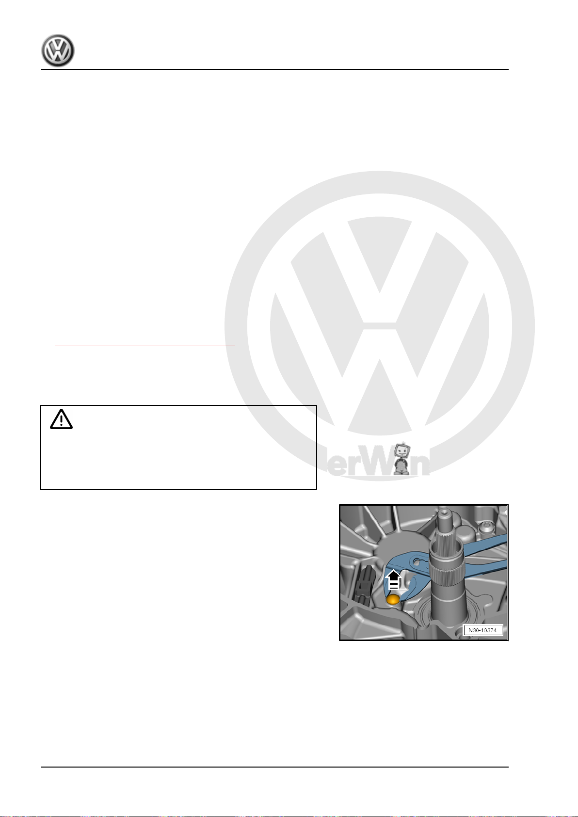
P
r
o
t
e
c
t
e
d
b
y
c
o
p
y
r
i
g
h
t
.
C
o
p
y
i
n
g
f
o
r
p
r
i
v
a
t
e
o
r
c
o
m
m
e
r
c
i
a
l
p
u
r
p
o
s
e
s
,
i
n
p
a
r
t
o
r
i
n
w
h
o
l
e
,
i
s
n
o
t
p
e
r
m
i
t
t
e
d
u
n
l
e
s
s
a
u
t
h
o
r
i
s
e
d
b
y
V
o
l
k
s
w
a
g
e
n
A
G
.
V
o
l
k
s
w
a
g
e
n
A
G
d
o
e
s
n
o
t
g
u
a
r
a
n
t
e
e
o
r
a
c
c
e
p
t
a
n
y
l
i
a
b
i
l
i
t
y
w
i
t
h
r
e
s
p
e
c
t
t
o
t
h
e
c
o
r
r
e
c
t
n
e
s
s
o
f
i
n
f
o
r
m
a
t
i
o
n
i
n
t
h
i
s
d
o
c
u
m
e
n
t
.
C
o
p
y
r
i
g
h
t
b
y
V
o
l
k
s
w
a
g
e
n
A
G
.
Jetta Hybrid 2013 ➤
Direct Shift Gearbox - Edition 01.2016
Short Description
♦ The position of the engaging bearing is comparable to clutch
play on a manual transmission. The engaging system in the
7-speed DSG® transmission 0CG and in the transmission it‐
self have tolerances. There are also tolerances within the dual
clutch. These tolerances must be taken into account sepa‐
rately when performing the adjustments.
♦ The following procedure describes how all necessary meas‐
urements are determined from the transmission side in order
to select the correct shim. In addition to this, the tolerances in
the dual clutch already determined by the manufacturer. The
transmission side tolerances and the tolerances in the dual
clutch determine the thickness of the shim.
♦ Follow the work sequence.
Special tools and workshop equipment required
♦ Digital Depth Gauge - 300mm - VAS6594-
♦ Gauge - Clutch Bearings - T10466-
♦ Ruler (2 pc.) - T40100-
Procedure
• The dual clutch is removed. Refer to
⇒ “2.2 DSG® Clutch, Removing”, page 33 .
• The transmission flange must be even so that it has a good
surface for the ruler.
• The DSG Transmission Mechatronic - J743- is installed in the
transmission.
Caution
Danger of damaging the dual clutch and other components.
• The mount for the engaging lever and the entire mechan‐
ical system for the engaging bearing must be dry and free
from oil and grease.
If Ball Stud Is Worn Down
– Remove the ball stud using pliers.
20 Rep. Gr.30 - Clutch
Page 25
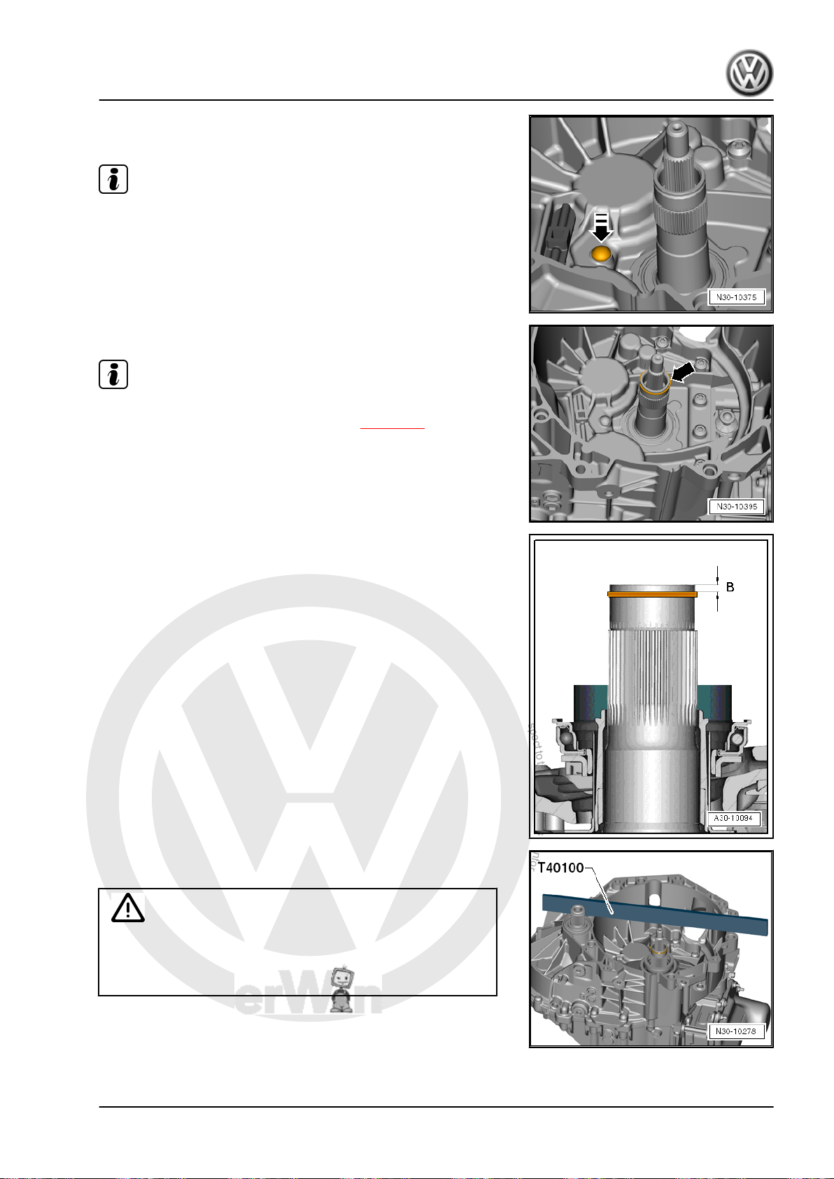
P
r
o
t
e
c
t
e
d
b
y
c
o
p
y
r
i
g
h
t
.
C
o
p
y
i
n
g
f
o
r
p
r
i
v
a
t
e
o
r
c
o
m
m
e
r
c
i
a
l
p
u
r
p
o
s
e
s
,
i
n
p
a
r
t
o
r
i
n
w
h
o
l
e
,
i
s
n
o
t
p
e
r
m
i
t
t
e
d
u
n
l
e
s
s
a
u
t
h
o
r
i
s
e
d
b
y
V
o
l
k
s
w
a
g
e
n
A
G
.
V
o
l
k
s
w
a
g
e
n
A
G
d
o
e
s
n
o
t
g
u
a
r
a
n
t
e
e
o
r
a
c
c
e
p
t
a
n
y
l
i
a
b
i
l
i
t
y
w
i
t
h
r
e
s
p
e
c
t
t
o
t
h
e
c
o
r
r
e
c
t
n
e
s
s
o
f
i
n
f
o
r
m
a
t
i
o
n
i
n
t
h
i
s
d
o
c
u
m
e
n
t
.
C
o
p
y
r
i
g
h
t
b
y
V
o
l
k
s
w
a
g
e
n
A
G
.
Direct Shift Gearbox - Edition 01.2016
– Install the new ball stud by hand. Use a plastic hammer and
drift gently, if necessary.
Note
Tap the drift with the plastic hammer gently to avoid damaging
the ball stud.
Continuation for All
Note
If dimension “B” was already measured, then step “2” of the
measurement can be made now. Refer to ⇒ page 23 .
– Install the previous locking ring -arrow- for the outer input
shaft.
Jetta Hybrid 2013 ➤
Step 1: Measure Dimension “B” for Clutch “K 1” and “K 2”.
– Place Ruler (2 pc.) - T40100- across the end of the shaft on
the transmission flange.
There is the risk of incorrect measurements.
♦ The Ruler (2 pc.) - T40100- should stay in this position for
Caution
the following measurements. Do not move it or take if off.
1. Clutch Mechanism 21
Page 26
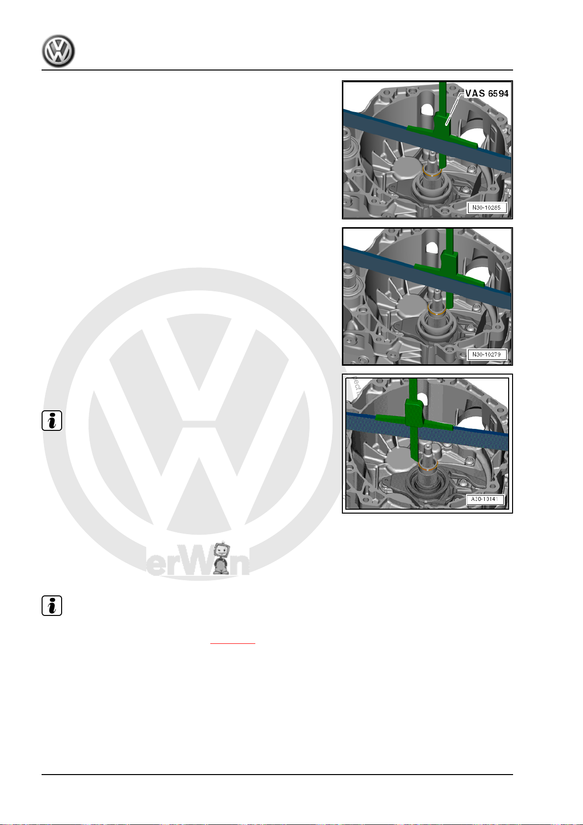
P
r
o
t
e
c
t
e
d
b
y
c
o
p
y
r
i
g
h
t
.
C
o
p
y
i
n
g
f
o
r
p
r
i
v
a
t
e
o
r
c
o
m
m
e
r
c
i
a
l
p
u
r
p
o
s
e
s
,
i
n
p
a
r
t
o
r
i
n
w
h
o
l
e
,
i
s
n
o
t
p
e
r
m
i
t
t
e
d
u
n
l
e
s
s
a
u
t
h
o
r
i
s
e
d
b
y
V
o
l
k
s
w
a
g
e
n
A
G
.
V
o
l
k
s
w
a
g
e
n
A
G
d
o
e
s
n
o
t
g
u
a
r
a
n
t
e
e
o
r
a
c
c
e
p
t
a
n
y
l
i
a
b
i
l
i
t
y
w
i
t
h
r
e
s
p
e
c
t
t
o
t
h
e
c
o
r
r
e
c
t
n
e
s
s
o
f
i
n
f
o
r
m
a
t
i
o
n
i
n
t
h
i
s
d
o
c
u
m
e
n
t
.
C
o
p
y
r
i
g
h
t
b
y
V
o
l
k
s
w
a
g
e
n
A
G
.
Jetta Hybrid 2013 ➤
Direct Shift Gearbox - Edition 01.2016
– Place the Digital Depth Gauge - 300mm - VAS6594- on top of
the Ruler (2 pc.) - T40100- and position the depth slide on the
outer input shaft.
– Set the depth gauge to “0”.
– Position the depth slide on the locking ring, as illustrated.
– Measure dimension “B1 ” on the locking ring in this position.
• Example: measurement “B1 ” = 2.62 mm
– Measure dimension “B2 ” on the opposite side of the locking
ring.
Note
Do not measure on the end of the locking ring. The locking ring
could get pushed away and this would invalidate the measure‐
ment.
• Example: dimension “B2 ” = 2.58 mm
– Calculate the mean value from “B1 ” and “B2 ”.
Formula: B1 + B2 2
Example:
• 2.62 + 2.582 = 2.60 mm
• Result: dimension “B” = 2.60 mm
Note
If the dual clutch is being installed according to this measurement,
then it must be removed now. Refer to ⇒ page 36 .
22 Rep. Gr.30 - Clutch
Page 27
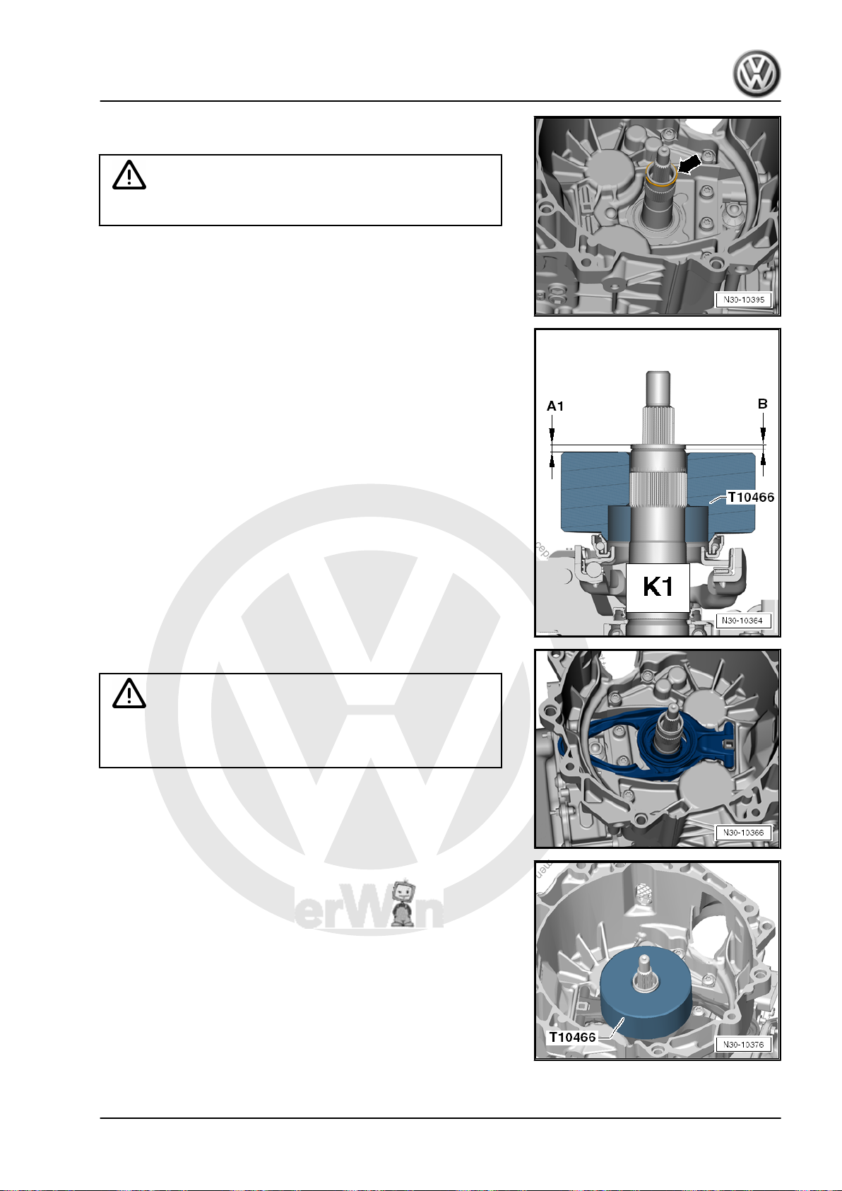
P
r
o
t
e
c
t
e
d
b
y
c
o
p
y
r
i
g
h
t
.
C
o
p
y
i
n
g
f
o
r
p
r
i
v
a
t
e
o
r
c
o
m
m
e
r
c
i
a
l
p
u
r
p
o
s
e
s
,
i
n
p
a
r
t
o
r
i
n
w
h
o
l
e
,
i
s
n
o
t
p
e
r
m
i
t
t
e
d
u
n
l
e
s
s
a
u
t
h
o
r
i
s
e
d
b
y
V
o
l
k
s
w
a
g
e
n
A
G
.
V
o
l
k
s
w
a
g
e
n
A
G
d
o
e
s
n
o
t
g
u
a
r
a
n
t
e
e
o
r
a
c
c
e
p
t
a
n
y
l
i
a
b
i
l
i
t
y
w
i
t
h
r
e
s
p
e
c
t
t
o
t
h
e
c
o
r
r
e
c
t
n
e
s
s
o
f
i
n
f
o
r
m
a
t
i
o
n
i
n
t
h
i
s
d
o
c
u
m
e
n
t
.
C
o
p
y
r
i
g
h
t
b
y
V
o
l
k
s
w
a
g
e
n
A
G
.
Direct Shift Gearbox - Edition 01.2016
– Remove the locking ring -arrow- from the outer input shaft and
throw it away.
Caution
Do not re-use the locking ring.
Step 2: Measure Dimension “A 1” for the Clutch Engaging Bearing
“K 1” .
– Install the large engaging lever.
– Make sure the engaging lever fits correctly.
– Place the Gauge - Clutch Bearings - T10466- on the large en‐
– Press and turn the Gauge - Clutch Bearings - T10466- to make
• The engaging bearing turns with the Gauge - Clutch Bearings
Caution
There is the risk of incorrect measurements.
♦ Do not install the shim.
gaging bearing. The flat side faces up
sure it seats correctly on the engaging bearing.
- T10466- .
Jetta Hybrid 2013 ➤
1. Clutch Mechanism 23
Page 28
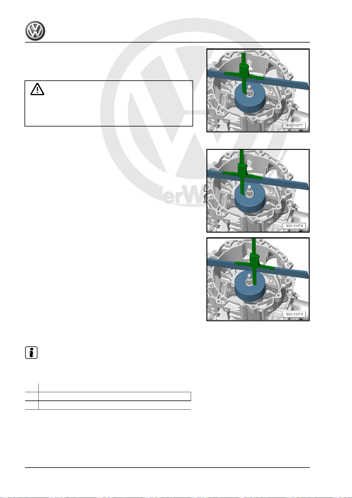
P
r
o
t
e
c
t
e
d
b
y
c
o
p
y
r
i
g
h
t
.
C
o
p
y
i
n
g
f
o
r
p
r
i
v
a
t
e
o
r
c
o
m
m
e
r
c
i
a
l
p
u
r
p
o
s
e
s
,
i
n
p
a
r
t
o
r
i
n
w
h
o
l
e
,
i
s
n
o
t
p
e
r
m
i
t
t
e
d
u
n
l
e
s
s
a
u
t
h
o
r
i
s
e
d
b
y
V
o
l
k
s
w
a
g
e
n
A
G
.
V
o
l
k
s
w
a
g
e
n
A
G
d
o
e
s
n
o
t
g
u
a
r
a
n
t
e
e
o
r
a
c
c
e
p
t
a
n
y
l
i
a
b
i
l
i
t
y
w
i
t
h
r
e
s
p
e
c
t
t
o
t
h
e
c
o
r
r
e
c
t
n
e
s
s
o
f
i
n
f
o
r
m
a
t
i
o
n
i
n
t
h
i
s
d
o
c
u
m
e
n
t
.
C
o
p
y
r
i
g
h
t
b
y
V
o
l
k
s
w
a
g
e
n
A
G
.
Jetta Hybrid 2013 ➤
Direct Shift Gearbox - Edition 01.2016
– Place the Digital Depth Gauge - 300mm - VAS6594- on top of
the ruler and position the depth slide on the outer input shaft.
• The Ruler (2 pc.) - T40100- lies straight across the transmis‐
sion flange over the end of the shaft.
Caution
There is the risk of incorrect measurements.
♦ The Ruler (2 pc.) - T40100- should stay in this position for
the following measurements. Do not move it or take if off.
– Set the depth gauge to “0”.
– Position the depth slide on the Gauge - Clutch Bearings -
T10466- , as illustrated.
– Measure dimension “A 1a ” on the Gauge - Clutch Bearings -
T10466- .
• Example: measurement “A 1a ” = 5.03 mm
– Measure dimension “A 1b ” on the other side of the Gauge -
Clutch Bearings - T10466- .
• Example: measurement “A 1b ” = 5.01 mm
– Calculate the average value from dimension “A 1a ” and “A
1b ”.
Formula: A 1a + A 1b 2
Example:
• 5.03 + 5.012 = 5.02 mm
• Result: dimension “A 1” = 5.02 mm
Step 3: Measuring the Height Tolerance for the Engaging Bearing
of Clutch “K 1”.
Note
Using dimension “A 1” and dimension “B”, calculate the height
tolerance for clutch “K 1” engaging bearing as follows:
Dimension “A 1”
– Dimension “B”
= Height tolerance for clutch “K 1” engaging bearing
Example:
• 5.02 mm - 2.60 mm = 2.42 mm
• Result: height tolerance for clutch “K 1” engaging bearing =
2.42 mm
24 Rep. Gr.30 - Clutch
Page 29

P
r
o
t
e
c
t
e
d
b
y
c
o
p
y
r
i
g
h
t
.
C
o
p
y
i
n
g
f
o
r
p
r
i
v
a
t
e
o
r
c
o
m
m
e
r
c
i
a
l
p
u
r
p
o
s
e
s
,
i
n
p
a
r
t
o
r
i
n
w
h
o
l
e
,
i
s
n
o
t
p
e
r
m
i
t
t
e
d
u
n
l
e
s
s
a
u
t
h
o
r
i
s
e
d
b
y
V
o
l
k
s
w
a
g
e
n
A
G
.
V
o
l
k
s
w
a
g
e
n
A
G
d
o
e
s
n
o
t
g
u
a
r
a
n
t
e
e
o
r
a
c
c
e
p
t
a
n
y
l
i
a
b
i
l
i
t
y
w
i
t
h
r
e
s
p
e
c
t
t
o
t
h
e
c
o
r
r
e
c
t
n
e
s
s
o
f
i
n
f
o
r
m
a
t
i
o
n
i
n
t
h
i
s
d
o
c
u
m
e
n
t
.
C
o
p
y
r
i
g
h
t
b
y
V
o
l
k
s
w
a
g
e
n
A
G
.
Direct Shift Gearbox - Edition 01.2016
Step 4: Measuring the Clutch Tolerance for Clutch “K 1”.
– Read the clutch tolerance value on the new clutch.
• Example: clutch tolerance read on the clutch “K 1 = +0.2”, as
illustrated.
• Result: clutch “K 1” clutch tolerance = + 0.20 mm.
Step 5: Measuring the Thickness of Shim “SK 1”.
Note
Using the clutch tolerance of clutch “K 1”, now the thickness of
shim “SK 1” can be calculated as follows:
Height tolerance for the engaging bearing “K 1”
–/+ Clutch tolerance for clutch “K 1”
= Calculated thickness for shim “SK 1”
Example:
• 2.42 mm + 0.20 mm = 2.62 mm
• Result: calculated shim thickness “SK 1” = 2.62 mm
Jetta Hybrid 2013 ➤
– Select the shim from the table using the part number
-magnifying glass- on the shim and lay it nearby for installation.
Calculated Shim
Thickness
mm
1.21 to 1.60 1.50 0AM 141 383
1.61 to 1.80 1.70 0AM 141 383 A
1.81 to 2.00 1.90 0AM 141 383 B
2.01 to 2.20 2.10 0AM 141 383 C
2.21 to 2.40 2.30 0AM 141 383 D
2.41 to 2.60 2.50 0AM 141 383 E
2.61 to 2.80 2.70 0AM 141 383 F
2.81 to 3.00 2.90 0AM 141 383 G
3.01 to 3.20 3.10 0AM 141 383 H
3.21 to 3.40 3.30 0AM 141 383 J
3.41 to 3.80 3.50 0AM 141 383 K
Example:
• Result: calculated shim thickness “SK 1” = 2.62 mm
• Selected shim thickness = 2.70 mm = part number 0AM 141
383 F
Caution
There is a risk of damaging the clutch.
♦ Later installed only this shim.
Available Shim
Thicknesses in mm
Shim Part Number
1. Clutch Mechanism 25
Page 30
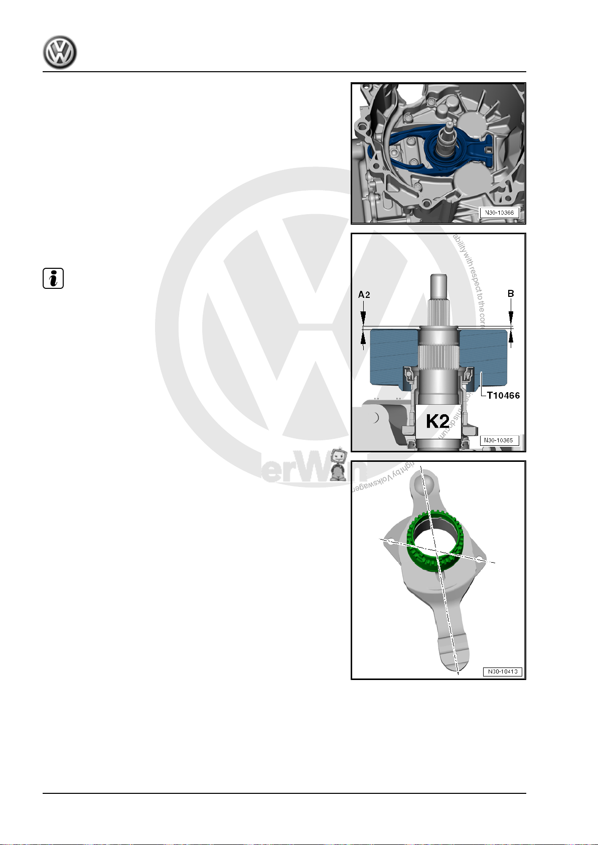
P
r
o
t
e
c
t
e
d
b
y
c
o
p
y
r
i
g
h
t
.
C
o
p
y
i
n
g
f
o
r
p
r
i
v
a
t
e
o
r
c
o
m
m
e
r
c
i
a
l
p
u
r
p
o
s
e
s
,
i
n
p
a
r
t
o
r
i
n
w
h
o
l
e
,
i
s
n
o
t
p
e
r
m
i
t
t
e
d
u
n
l
e
s
s
a
u
t
h
o
r
i
s
e
d
b
y
V
o
l
k
s
w
a
g
e
n
A
G
.
V
o
l
k
s
w
a
g
e
n
A
G
d
o
e
s
n
o
t
g
u
a
r
a
n
t
e
e
o
r
a
c
c
e
p
t
a
n
y
l
i
a
b
i
l
i
t
y
w
i
t
h
r
e
s
p
e
c
t
t
o
t
h
e
c
o
r
r
e
c
t
n
e
s
s
o
f
i
n
f
o
r
m
a
t
i
o
n
i
n
t
h
i
s
d
o
c
u
m
e
n
t
.
C
o
p
y
r
i
g
h
t
b
y
V
o
l
k
s
w
a
g
e
n
A
G
.
Jetta Hybrid 2013 ➤
Direct Shift Gearbox - Edition 01.2016
– Remove the Gauge - Clutch Bearings - T10466- and large en‐
gaging lever.
Step 6: Calculating Dimension “A 2” for Clutch “K 2” Engaging
Bearing
Note
The guide sleeve upper section cannot be removed or installed
separately. It is always removed and installed together with the
guide sleeve lower section and the small engaging lever.
Note the Following When Installing A New Engaging Lever »K 2«:
A new engaging lever »K 2« with guide sleeve upper and lower
sections are in their transportation position when they are deliv‐
ered -illustration-. It is necessary to first move them into their
installation position before installing them.
Bringing the engaging lever »K 2« into the installed position as
follows:
26 Rep. Gr.30 - Clutch
Page 31
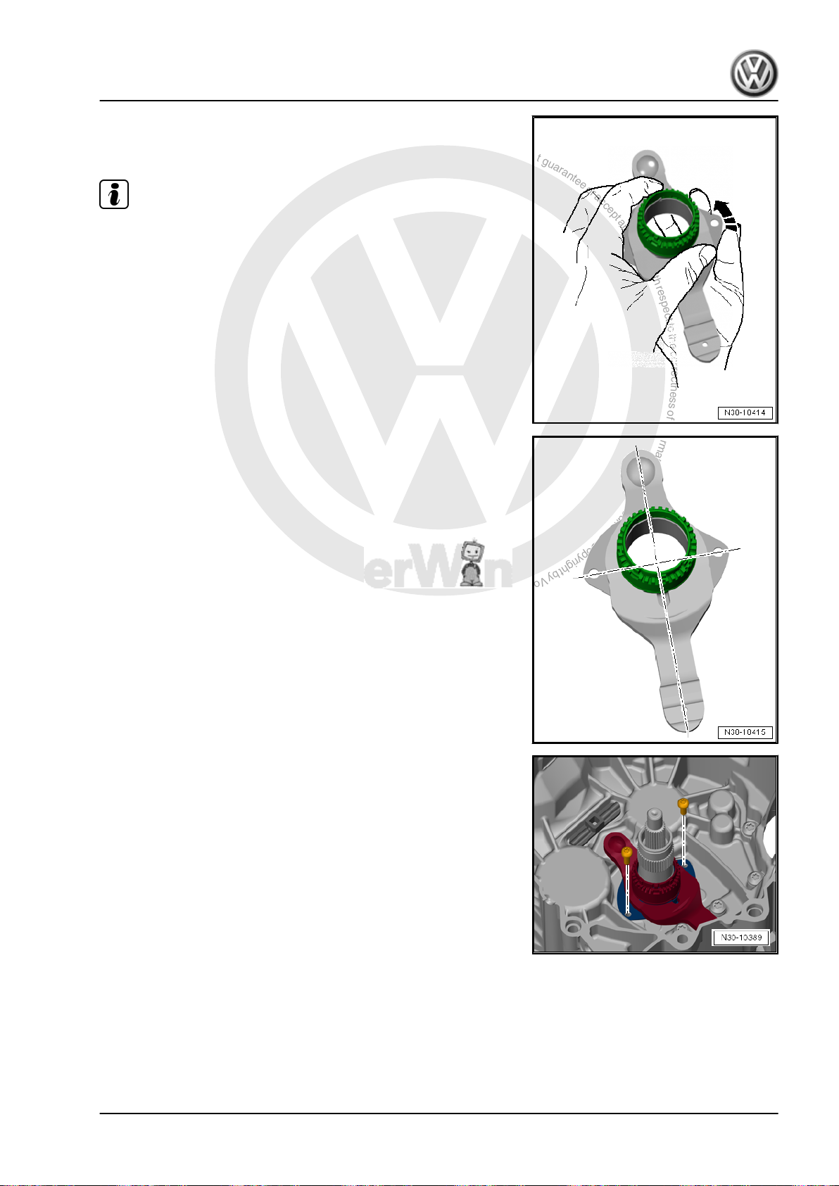
P
r
o
t
e
c
t
e
d
b
y
c
o
p
y
r
i
g
h
t
.
C
o
p
y
i
n
g
f
o
r
p
r
i
v
a
t
e
o
r
c
o
m
m
e
r
c
i
a
l
p
u
r
p
o
s
e
s
,
i
n
p
a
r
t
o
r
i
n
w
h
o
l
e
,
i
s
n
o
t
p
e
r
m
i
t
t
e
d
u
n
l
e
s
s
a
u
t
h
o
r
i
s
e
d
b
y
V
o
l
k
s
w
a
g
e
n
A
G
.
V
o
l
k
s
w
a
g
e
n
A
G
d
o
e
s
n
o
t
g
u
a
r
a
n
t
e
e
o
r
a
c
c
e
p
t
a
n
y
l
i
a
b
i
l
i
t
y
w
i
t
h
r
e
s
p
e
c
t
t
o
t
h
e
c
o
r
r
e
c
t
n
e
s
s
o
f
i
n
f
o
r
m
a
t
i
o
n
i
n
t
h
i
s
d
o
c
u
m
e
n
t
.
C
o
p
y
r
i
g
h
t
b
y
V
o
l
k
s
w
a
g
e
n
A
G
.
Jetta Hybrid 2013 ➤
Direct Shift Gearbox - Edition 01.2016
– Hold the guide sleeve upper section with one hand. Turn the
guide sleeve lower section in direction of -arrow- with the other
hand until the sleeve moves freely.
Note
Hold both parts securely because a lot of force is needed to turn
the guide sleeve lower section.
In the installed position, the holes in the guide sleeve lower sec‐
tion are at a right angle to the engaging lever and the sleeve can
be moved freely.
Continuation for All
– Install the small engaging lever with the upper and lower sec‐
tions of the guide sleeve. Install new bolts and tighten them.
1. Clutch Mechanism 27
Page 32
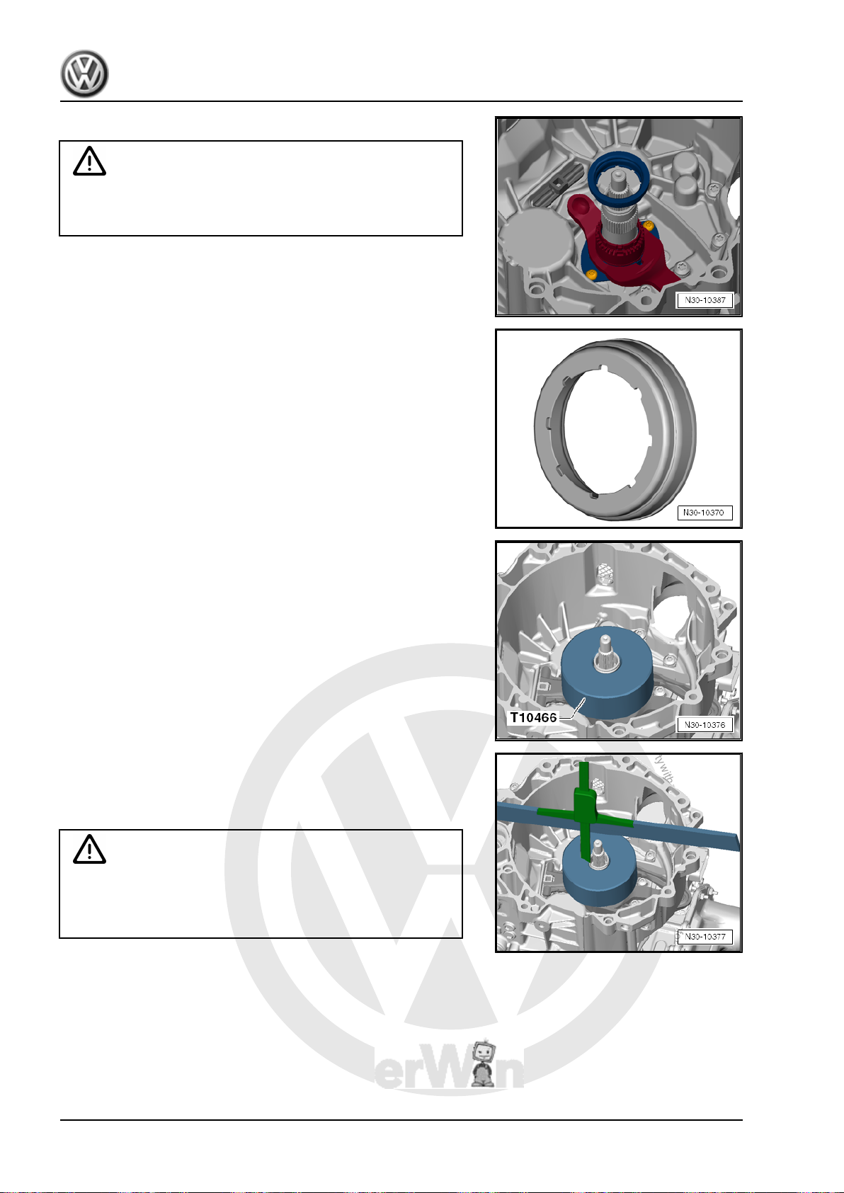
P
r
o
t
e
c
t
e
d
b
y
c
o
p
y
r
i
g
h
t
.
C
o
p
y
i
n
g
f
o
r
p
r
i
v
a
t
e
o
r
c
o
m
m
e
r
c
i
a
l
p
u
r
p
o
s
e
s
,
i
n
p
a
r
t
o
r
i
n
w
h
o
l
e
,
i
s
n
o
t
p
e
r
m
i
t
t
e
d
u
n
l
e
s
s
a
u
t
h
o
r
i
s
e
d
b
y
V
o
l
k
s
w
a
g
e
n
A
G
.
V
o
l
k
s
w
a
g
e
n
A
G
d
o
e
s
n
o
t
g
u
a
r
a
n
t
e
e
o
r
a
c
c
e
p
t
a
n
y
l
i
a
b
i
l
i
t
y
w
i
t
h
r
e
s
p
e
c
t
t
o
t
h
e
c
o
r
r
e
c
t
n
e
s
s
o
f
i
n
f
o
r
m
a
t
i
o
n
i
n
t
h
i
s
d
o
c
u
m
e
n
t
.
C
o
p
y
r
i
g
h
t
b
y
V
o
l
k
s
w
a
g
e
n
A
G
.
Jetta Hybrid 2013 ➤
Direct Shift Gearbox - Edition 01.2016
– Install the small engaging bearing without the shim.
Caution
There is the risk of incorrect measurements.
♦ Do not install the shim.
• The small engaging bearing fits in only one position due to the
8 grooves.
– Turn the small engaging bearing to make sure it is installed
correctly and fits correctly in the grooves.
– Place the Gauge - Clutch Bearings - T10466- on the small
engaging bearing. The flat side faces up
– Press and turn the Gauge - Clutch Bearings - T10466- to make
sure it seats correctly on the engaging bearing.
• The engaging bearing turns with the Gauge - Clutch Bearings
- T10466- .
– Place the Digital Depth Gauge - 300mm - VAS6594- on top of
the ruler and position the depth slide on the outer input shaft.
• The Ruler (2 pc.) - T40100- lies straight across the transmis‐
sion flange over the end of the shaft.
Caution
There is the risk of incorrect measurements.
♦ The Ruler (2 pc.) - T40100- should stay in this position for
the following measurements. Do not move it or take if off.
– Set the depth gauge to “0”.
28 Rep. Gr.30 - Clutch
Page 33
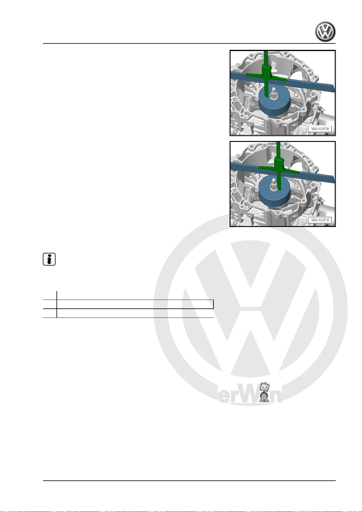
P
r
o
t
e
c
t
e
d
b
y
c
o
p
y
r
i
g
h
t
.
C
o
p
y
i
n
g
f
o
r
p
r
i
v
a
t
e
o
r
c
o
m
m
e
r
c
i
a
l
p
u
r
p
o
s
e
s
,
i
n
p
a
r
t
o
r
i
n
w
h
o
l
e
,
i
s
n
o
t
p
e
r
m
i
t
t
e
d
u
n
l
e
s
s
a
u
t
h
o
r
i
s
e
d
b
y
V
o
l
k
s
w
a
g
e
n
A
G
.
V
o
l
k
s
w
a
g
e
n
A
G
d
o
e
s
n
o
t
g
u
a
r
a
n
t
e
e
o
r
a
c
c
e
p
t
a
n
y
l
i
a
b
i
l
i
t
y
w
i
t
h
r
e
s
p
e
c
t
t
o
t
h
e
c
o
r
r
e
c
t
n
e
s
s
o
f
i
n
f
o
r
m
a
t
i
o
n
i
n
t
h
i
s
d
o
c
u
m
e
n
t
.
C
o
p
y
r
i
g
h
t
b
y
V
o
l
k
s
w
a
g
e
n
A
G
.
Direct Shift Gearbox - Edition 01.2016
– Position the depth slide on the Gauge - Clutch Bearings -
T10466- , as illustrated.
– Measure dimension “A 2a ” on the Gauge - Clutch Bearings -
T10466- .
• Example: dimension “A 2a ” = 4.79 mm
– Measure dimension “A 2b ” on the other side of the Gauge -
Clutch Bearings - T10466- .
• Example: dimension “A 2b ” = 4.75 mm
– Calculate the average value from dimension “A 2a ” and “A
2b ”.
Formula: A 2a + A 2b 2
Jetta Hybrid 2013 ➤
Example:
• 4,79 + 4,752 = 4.77 mm
• Result: dimension “A 2” = 4.77 mm
Step 7: Measuring the Height Tolerance For the Engaging Bear‐
ing of Clutch “K 2”.
Note
Using dimension “A 2” and dimension “B”, calculate the height
tolerance for clutch “K 2” engaging bearing as follows:
Dimension “A 2”
– Dimension “B”
= Height tolerance for clutch “K 2” engaging bearing
Example:
• 4.77 mm - 2.60 mm = 2.17 mm
• Result: height tolerance for clutch “K 2” engaging bearing =
2.17 mm
1. Clutch Mechanism 29
Page 34
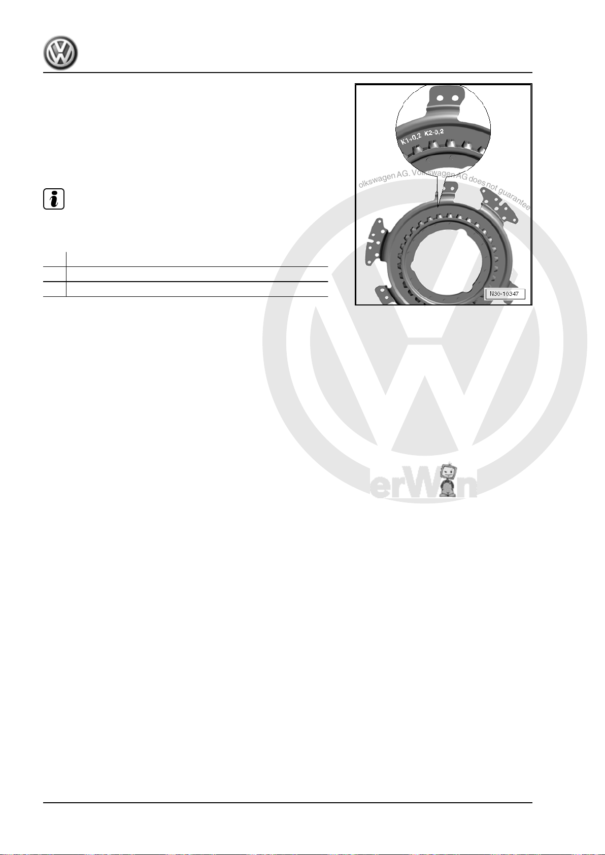
P
r
o
t
e
c
t
e
d
b
y
c
o
p
y
r
i
g
h
t
.
C
o
p
y
i
n
g
f
o
r
p
r
i
v
a
t
e
o
r
c
o
m
m
e
r
c
i
a
l
p
u
r
p
o
s
e
s
,
i
n
p
a
r
t
o
r
i
n
w
h
o
l
e
,
i
s
n
o
t
p
e
r
m
i
t
t
e
d
u
n
l
e
s
s
a
u
t
h
o
r
i
s
e
d
b
y
V
o
l
k
s
w
a
g
e
n
A
G
.
V
o
l
k
s
w
a
g
e
n
A
G
d
o
e
s
n
o
t
g
u
a
r
a
n
t
e
e
o
r
a
c
c
e
p
t
a
n
y
l
i
a
b
i
l
i
t
y
w
i
t
h
r
e
s
p
e
c
t
t
o
t
h
e
c
o
r
r
e
c
t
n
e
s
s
o
f
i
n
f
o
r
m
a
t
i
o
n
i
n
t
h
i
s
d
o
c
u
m
e
n
t
.
C
o
p
y
r
i
g
h
t
b
y
V
o
l
k
s
w
a
g
e
n
A
G
.
Jetta Hybrid 2013 ➤
Direct Shift Gearbox - Edition 01.2016
Step 8: Measuring the Clutch Tolerance for Clutch “K 2”.
– Read the clutch tolerance value on the new clutch.
• Example: clutch tolerance read on the clutch “K 2 = – 0.2”, as
illustrated.
• Result: clutch “K 2” clutch tolerance = – 0.20 mm.
Step 9: Measuring the Thickness of Shim “SK 2”.
Note
Using the clutch tolerance of clutch “K 2”, now the thickness of
shim “SK 2” can be calculated as follows:
Height tolerance for the engaging bearing “K 2”
–/+ Clutch tolerance for the clutch “K 2”
= Calculated thickness for shim “SK 2”
Example:
• 2.17 mm – 0.20 mm = 1.97 mm
• Result: calculated shim thickness “SK 2” = 1.97 mm
30 Rep. Gr.30 - Clutch
Page 35
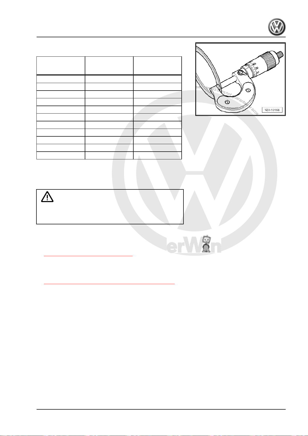
P
r
o
t
e
c
t
e
d
b
y
c
o
p
y
r
i
g
h
t
.
C
o
p
y
i
n
g
f
o
r
p
r
i
v
a
t
e
o
r
c
o
m
m
e
r
c
i
a
l
p
u
r
p
o
s
e
s
,
i
n
p
a
r
t
o
r
i
n
w
h
o
l
e
,
i
s
n
o
t
p
e
r
m
i
t
t
e
d
u
n
l
e
s
s
a
u
t
h
o
r
i
s
e
d
b
y
V
o
l
k
s
w
a
g
e
n
A
G
.
V
o
l
k
s
w
a
g
e
n
A
G
d
o
e
s
n
o
t
g
u
a
r
a
n
t
e
e
o
r
a
c
c
e
p
t
a
n
y
l
i
a
b
i
l
i
t
y
w
i
t
h
r
e
s
p
e
c
t
t
o
t
h
e
c
o
r
r
e
c
t
n
e
s
s
o
f
i
n
f
o
r
m
a
t
i
o
n
i
n
t
h
i
s
d
o
c
u
m
e
n
t
.
C
o
p
y
r
i
g
h
t
b
y
V
o
l
k
s
w
a
g
e
n
A
G
.
Direct Shift Gearbox - Edition 01.2016
– Measure the needed shim from the shims supplied and keep
it close for installation.
Jetta Hybrid 2013 ➤
Calculated shim
thickness
Available shim
thicknesses in mm
Shim part number
mm
0.31 to 0.90 0.80 WHT 005 518
0.91 to 1.10 1.00 WHT 005 518 A
1.11 to 1.30 1.20 WHT 005 518 B
1.31 to 1.50 1.40 WHT 005 518 C
1.51 to 1.70 1.60 WHT 005 518 D
1.71 to 1.90 1.80 WHT 005 518 E
1.91 to 2.10 2.00 WHT 005 518 F
2.11 to 2.30 2.20 WHT 005 518 G
2.31 to 2.50 2.40 WHT 005 518 H
2.51 to 2.70 2.60 WHT 005 518 J
2.71 to 3.30 2.80 WHT 005 518 K
Example:
• Result: calculated shim thickness “SK 2” = 1.97 mm
• Selected shim thickness = 2.00 mm
There is a risk of damaging the clutch.
Caution
♦ Later installed only this shim.
The adjustment is now completed and the small engaging lever
is already installed.
– Install the dual clutch. Refer to
⇒ “2.3 Dual Clutch, Installing”, page 37 .
Tightening Specifications
♦ Guide sleeve lower section with small engaging lever to trans‐
mission housing. Refer to
⇒ “1.1 Overview - Clutch Engaging Mechanism”, page 15 .
1. Clutch Mechanism 31
Page 36
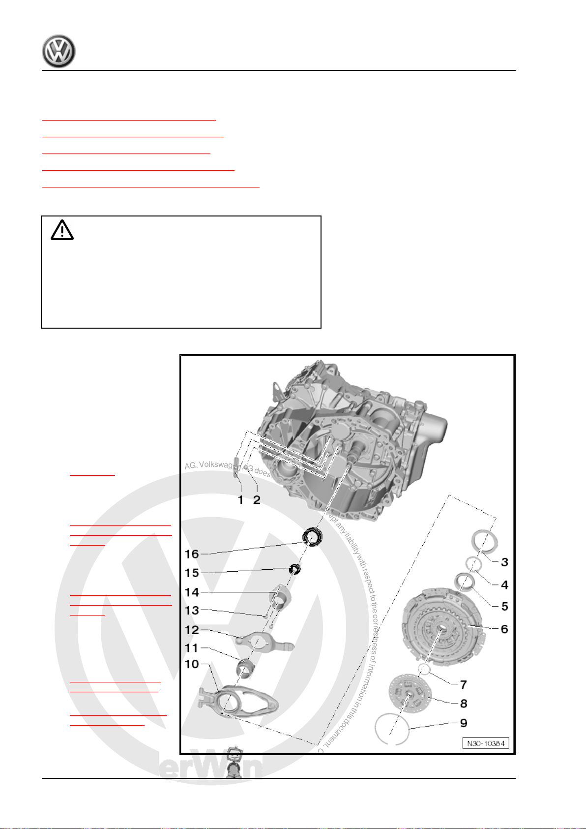
P
r
o
t
e
c
t
e
d
b
y
c
o
p
y
r
i
g
h
t
.
C
o
p
y
i
n
g
f
o
r
p
r
i
v
a
t
e
o
r
c
o
m
m
e
r
c
i
a
l
p
u
r
p
o
s
e
s
,
i
n
p
a
r
t
o
r
i
n
w
h
o
l
e
,
i
s
n
o
t
p
e
r
m
i
t
t
e
d
u
n
l
e
s
s
a
u
t
h
o
r
i
s
e
d
b
y
V
o
l
k
s
w
a
g
e
n
A
G
.
V
o
l
k
s
w
a
g
e
n
A
G
d
o
e
s
n
o
t
g
u
a
r
a
n
t
e
e
o
r
a
c
c
e
p
t
a
n
y
l
i
a
b
i
l
i
t
y
w
i
t
h
r
e
s
p
e
c
t
t
o
t
h
e
c
o
r
r
e
c
t
n
e
s
s
o
f
i
n
f
o
r
m
a
t
i
o
n
i
n
t
h
i
s
d
o
c
u
m
e
n
t
.
C
o
p
y
r
i
g
h
t
b
y
V
o
l
k
s
w
a
g
e
n
A
G
.
Jetta Hybrid 2013 ➤
Direct Shift Gearbox - Edition 01.2016
2 Clutch
⇒ “2.1 Overview - Dual Clutch”, page 32
⇒ “2.2 DSG® Clutch, Removing”, page 33
⇒ “2.3 Dual Clutch, Installing”, page 37
⇒ “2.4 Input Shaft Seal, Replacing”, page 41
⇒ “2.5 Inner Input Shaft Seal, Replacing”, page 43
2.1 Overview - Dual Clutch
Caution
Danger of causing damage to the dual clutch adjusting tool.
♦ The dual clutch is self-adjusting. Vibrations can affect the
adjusting tool. Be careful not to drop the dual clutch into
the transmission when installing.
♦ Do not install a dual clutch that has fallen onto a hard sur‐
face or shows signs of damage.
1 - Engaging Lever Support
❑ For the large engaging
lever “K 1”
❑ Cannot be replaced
2 - Ball Stud
❑ For the small engaging
lever “K 2”
❑ Removing and instal‐
ling. Refer to
⇒ page 20 .
3 - Shim “SK 1”
❑ Selecting thickness. Re‐
fer to
⇒ “1.3 Clutch Engaging
Mechanism, Adjusting”,
page 19 .
4 - Shim “SK 2”
❑ Selecting thickness. Re‐
fer to
⇒ “1.3 Clutch Engaging
Mechanism, Adjusting”,
page 19 .
5 - Small Engaging Bearing for
“K 2”
6 - Dual Clutch
❑ Removing. Refer to
⇒ “2.2 DSG® Clutch,
Removing”, page 33 .
❑ Installing. Refer to
⇒ “2.3 Dual Clutch, In‐
stalling”, page 37 .
7 - Locking Ring
❑ Replace after removing
32 Rep. Gr.30 - Clutch
Page 37

P
r
o
t
e
c
t
e
d
b
y
c
o
p
y
r
i
g
h
t
.
C
o
p
y
i
n
g
f
o
r
p
r
i
v
a
t
e
o
r
c
o
m
m
e
r
c
i
a
l
p
u
r
p
o
s
e
s
,
i
n
p
a
r
t
o
r
i
n
w
h
o
l
e
,
i
s
n
o
t
p
e
r
m
i
t
t
e
d
u
n
l
e
s
s
a
u
t
h
o
r
i
s
e
d
b
y
V
o
l
k
s
w
a
g
e
n
A
G
.
V
o
l
k
s
w
a
g
e
n
A
G
d
o
e
s
n
o
t
g
u
a
r
a
n
t
e
e
o
r
a
c
c
e
p
t
a
n
y
l
i
a
b
i
l
i
t
y
w
i
t
h
r
e
s
p
e
c
t
t
o
t
h
e
c
o
r
r
e
c
t
n
e
s
s
o
f
i
n
f
o
r
m
a
t
i
o
n
i
n
t
h
i
s
d
o
c
u
m
e
n
t
.
C
o
p
y
r
i
g
h
t
b
y
V
o
l
k
s
w
a
g
e
n
A
G
.
Jetta Hybrid 2013 ➤
Direct Shift Gearbox - Edition 01.2016
8 - Hub
9 - Locking Ring
❑ Replace after removing
10 - Large Engaging Lever “K 1”
❑ With engaging bearing
❑ Removing and installing. Refer to
⇒ “1.2 Clutch Engaging Mechanism, Removing and Installing”, page 16 .
11 - Guide Sleeve Upper Section
❑ For the small engaging lever “K 2”
❑ Is removed and installed together with the small engaging lever and the guide sleeve lower section
12 - Small Engaging Lever for “K 2”
❑ Is removed and installed together with the guide sleeve upper section and lower section
❑ Removing and installing. Refer to
⇒ “1.2 Clutch Engaging Mechanism, Removing and Installing”, page 16 .
13 - Bolts
❑ 8 Nm +90° turn
❑ Replace after removing
14 - Guide Sleeve Lower Section
❑ For the small engaging lever “K 2”
❑ Is removed and installed together with the small engaging lever and the guide sleeve upper section
15 - Seal
❑ For the inner input shaft
❑ ⇒ “2.5 Inner Input Shaft Seal, Replacing”, page 43
16 - Seal
❑ For the outer input shaft
❑ Replacing. Refer to ⇒ “2.4 Input Shaft Seal, Replacing”, page 41
2.2 DSG® Clutch, Removing
Special tools and workshop equipment required
♦ T-Handle Hook - 3438-
♦ Engine Bung Set - VAS6122-
♦ Support Bridge - T10323-
♦ Subframe Bushing Assembly Tool Kit -Assembly Tool 5 -
T10356/5- from the Subframe Bushing Assembly Tool Kit T10356-
♦ Puller - Clutch - T10373-
♦ Clutch Press Piece - T10376-
♦ Protective Cap - 0AM 325 120 A- quantity 1 and Protective
Cap - 02M 409 120- quantity 1, as an alternative to the Engine
Bung Set - VAS6122-
2. Clutch 33
Page 38
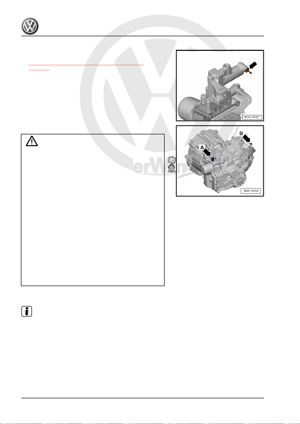
P
r
o
t
e
c
t
e
d
b
y
c
o
p
y
r
i
g
h
t
.
C
o
p
y
i
n
g
f
o
r
p
r
i
v
a
t
e
o
r
c
o
m
m
e
r
c
i
a
l
p
u
r
p
o
s
e
s
,
i
n
p
a
r
t
o
r
i
n
w
h
o
l
e
,
i
s
n
o
t
p
e
r
m
i
t
t
e
d
u
n
l
e
s
s
a
u
t
h
o
r
i
s
e
d
b
y
V
o
l
k
s
w
a
g
e
n
A
G
.
V
o
l
k
s
w
a
g
e
n
A
G
d
o
e
s
n
o
t
g
u
a
r
a
n
t
e
e
o
r
a
c
c
e
p
t
a
n
y
l
i
a
b
i
l
i
t
y
w
i
t
h
r
e
s
p
e
c
t
t
o
t
h
e
c
o
r
r
e
c
t
n
e
s
s
o
f
i
n
f
o
r
m
a
t
i
o
n
i
n
t
h
i
s
d
o
c
u
m
e
n
t
.
C
o
p
y
r
i
g
h
t
b
y
V
o
l
k
s
w
a
g
e
n
A
G
.
Jetta Hybrid 2013 ➤
Direct Shift Gearbox - Edition 01.2016
Requirement
• The transmission is removed and mounted to the engine/
transmission holder. Refer to
⇒ “5 Securing on Engine and Transmission Holder”,
page 102 .
• The DSG Transmission Mechatronic - J743- is installed in the
transmission.
• The connection on the valve block/Mechatronic is sealed with
a new sealing plug -arrow- from the Repair Kit - 5C0 998 152- .
Removing
Caution
Danger of causing damage to the transmission.
The vent on the DSG Transmission Mechatronic - J743(-arrow A-) and the transmission ventilation (-arrow B-) must
be sealed tight so that no fluid can leak out.
♦ Hydraulic fluid that has leaked out of the DSG Transmis‐
sion Mechatronic - J743- may not refilled. Checking the
hydraulic fluid level in the DSG Transmission Mechatronic
- J743- is not possible.
♦ Should hydraulic fluid leak out, it is possible to add new
fluid using via the vent on the Mechatronic . For the correct
hydraulic fluid, sealing plugs and disposable syringe from
the Repair Kit - 5C0 998 152- . Refer to the Parts Catalog.
Perform the filling as soon as possible after installing the
transmission in the vehicle. Dispose of the remaining hy‐
draulic fluid and sealing plugs with the disposable syringe.
♦ If transmission fluid has leaked out, then it is necessary to
perform a transmission fluid replacement. It is not possible
to check the fluid level.
♦ Under filling or overfilling both fluid systems will impair the
function of the transmission.
♦ The vent cap -arrow A- on the Mechatronic will get dam‐
aged when being removed and must be replaced.
– Remove both caps -arrow A and B-.
Note
As an alternative to the Engine Bung Set - VAS6122- the Protec‐
tive Cap - 02M 409 120- can be used to seal the transmission.
The Protective Cap - 0AM 325 120 A- can also be used to seal
the Mechatronic securely. Refer to the Parts Catalog.
– Seal off the transmission ventilation on the DSG Transmission
Mechatronic - J743- with clean plugs so that no fluid can leak
out.
34 Rep. Gr.30 - Clutch
Page 39
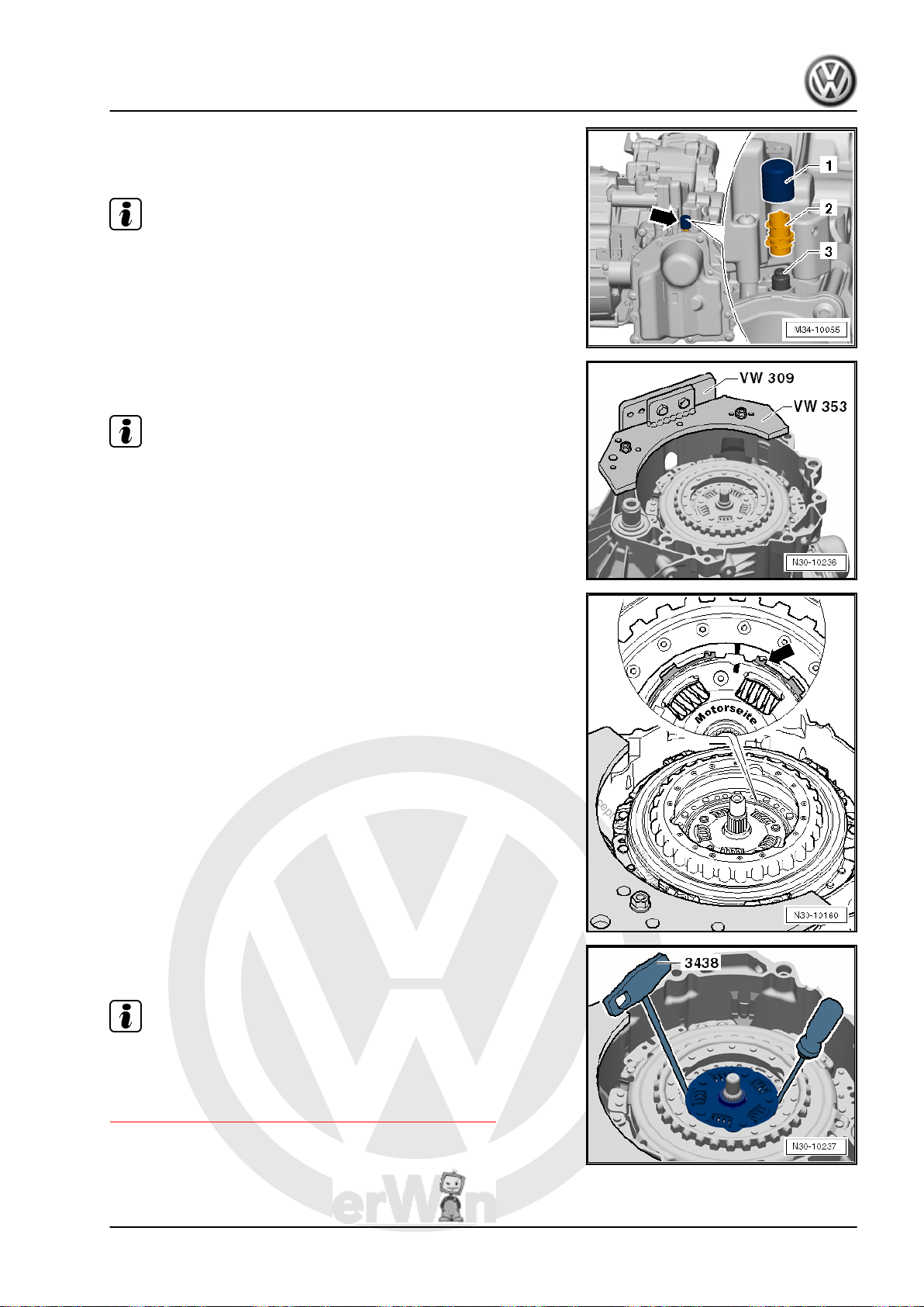
P
r
o
t
e
c
t
e
d
b
y
c
o
p
y
r
i
g
h
t
.
C
o
p
y
i
n
g
f
o
r
p
r
i
v
a
t
e
o
r
c
o
m
m
e
r
c
i
a
l
p
u
r
p
o
s
e
s
,
i
n
p
a
r
t
o
r
i
n
w
h
o
l
e
,
i
s
n
o
t
p
e
r
m
i
t
t
e
d
u
n
l
e
s
s
a
u
t
h
o
r
i
s
e
d
b
y
V
o
l
k
s
w
a
g
e
n
A
G
.
V
o
l
k
s
w
a
g
e
n
A
G
d
o
e
s
n
o
t
g
u
a
r
a
n
t
e
e
o
r
a
c
c
e
p
t
a
n
y
l
i
a
b
i
l
i
t
y
w
i
t
h
r
e
s
p
e
c
t
t
o
t
h
e
c
o
r
r
e
c
t
n
e
s
s
o
f
i
n
f
o
r
m
a
t
i
o
n
i
n
t
h
i
s
d
o
c
u
m
e
n
t
.
C
o
p
y
r
i
g
h
t
b
y
V
o
l
k
s
w
a
g
e
n
A
G
.
Direct Shift Gearbox - Edition 01.2016
– Order a new cap -arrow- for the DSG Transmission Mecha‐
tronic - J743- . It must be replaced after installing the trans‐
mission. Refer to the Parts Catalog.
Note
The replacement vent -2- and cap -1- are a single component and
is pushed onto the ventilation -3-.
• Remove the plugs after installing the transmission into the ve‐
hicle and re-install or replace the vent caps.
– Turn the transmission on the engine/transmission holder with
the dual clutch facing up.
Note
The dual clutch is removed upward. The Mechatronic stays on
the transmission.
Jetta Hybrid 2013 ➤
– Remove the locking ring -arrow- from the hub.
driver.
Note
– Remove the hub using T-Handle Hook - 3438- and a screw‐
It is necessary to adjust the position of the engaging bearings “K
1” and “K 2” later when dual clutch components are replaced. It
is advisable to determine dimension “B” for the measurements.
Refer to
⇒ “1.3 Clutch Engaging Mechanism, Adjusting”, page 19 .
2. Clutch 35
Page 40
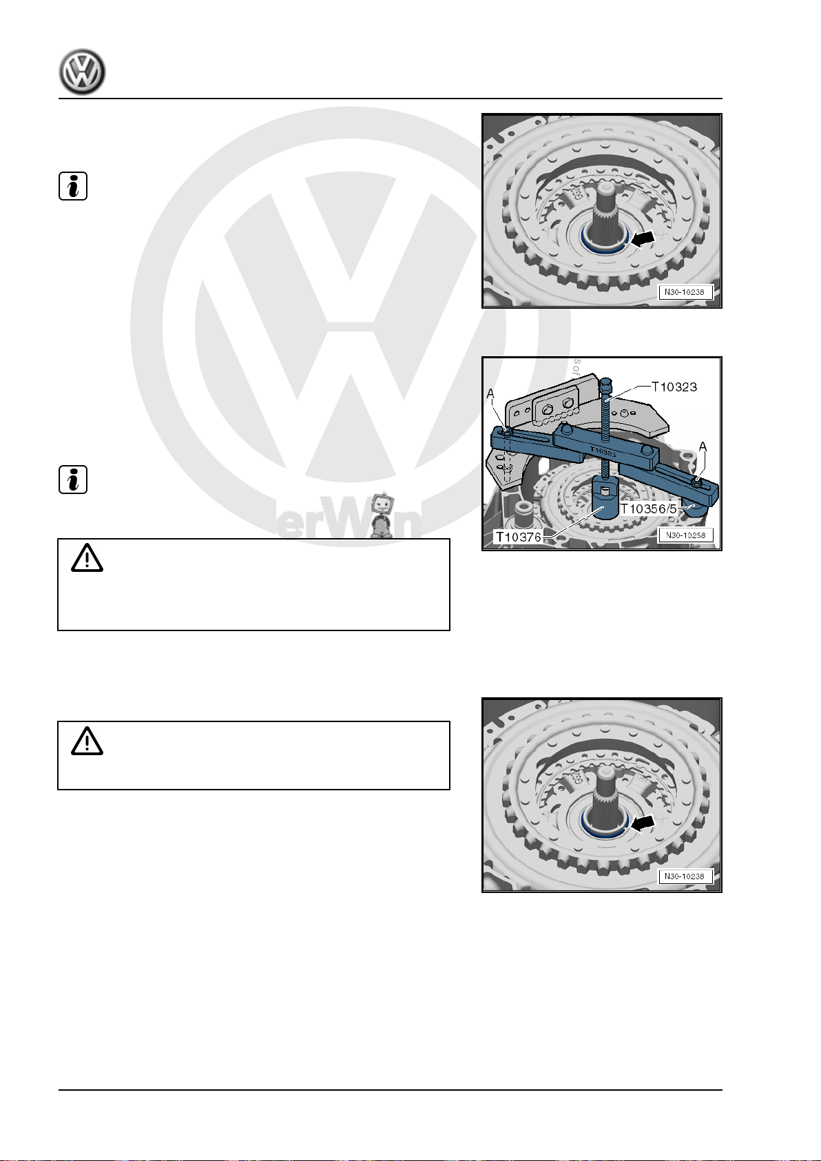
P
r
o
t
e
c
t
e
d
b
y
c
o
p
y
r
i
g
h
t
.
C
o
p
y
i
n
g
f
o
r
p
r
i
v
a
t
e
o
r
c
o
m
m
e
r
c
i
a
l
p
u
r
p
o
s
e
s
,
i
n
p
a
r
t
o
r
i
n
w
h
o
l
e
,
i
s
n
o
t
p
e
r
m
i
t
t
e
d
u
n
l
e
s
s
a
u
t
h
o
r
i
s
e
d
b
y
V
o
l
k
s
w
a
g
e
n
A
G
.
V
o
l
k
s
w
a
g
e
n
A
G
d
o
e
s
n
o
t
g
u
a
r
a
n
t
e
e
o
r
a
c
c
e
p
t
a
n
y
l
i
a
b
i
l
i
t
y
w
i
t
h
r
e
s
p
e
c
t
t
o
t
h
e
c
o
r
r
e
c
t
n
e
s
s
o
f
i
n
f
o
r
m
a
t
i
o
n
i
n
t
h
i
s
d
o
c
u
m
e
n
t
.
C
o
p
y
r
i
g
h
t
b
y
V
o
l
k
s
w
a
g
e
n
A
G
.
Jetta Hybrid 2013 ➤
Direct Shift Gearbox - Edition 01.2016
– Remove the locking ring -arrow- from the dual clutch.
If it is Not Possible to Remove the Locking Ring
Note
♦
The dual clutch will »jam« the locking ring from underneath if
it is not possible to remove the locking ring.
♦
If this is the case, then push the dual clutch slightly down as
described in the following and this will release the pressure on
the locking ring. Never hit the dual clutch or the shaft with a
hammer.
♦
Always replace the locking ring.
– Position the Support Bridge - T1032- parallel to the transmis‐
sion flange, as illustrated.
– If necessary, even out the gaps, for example, with Subframe
Bushing Assembly Tool Kit -Assembly Tool 5 - T10356/5- .
– Tighten the bolts -A- hand-tight.
Note
Secure the bolts -A- with a nut, if needed.
Caution
Danger of damaging the dual clutch and other components.
• Push the dual clutch down gently without pressing.
– Turn the spindle against the Clutch Press Piece - T10376- to
lower it.
– Remove the locking ring -arrow- from the dual clutch.
Caution
Do not re-use the locking ring.
36 Rep. Gr.30 - Clutch
Page 41
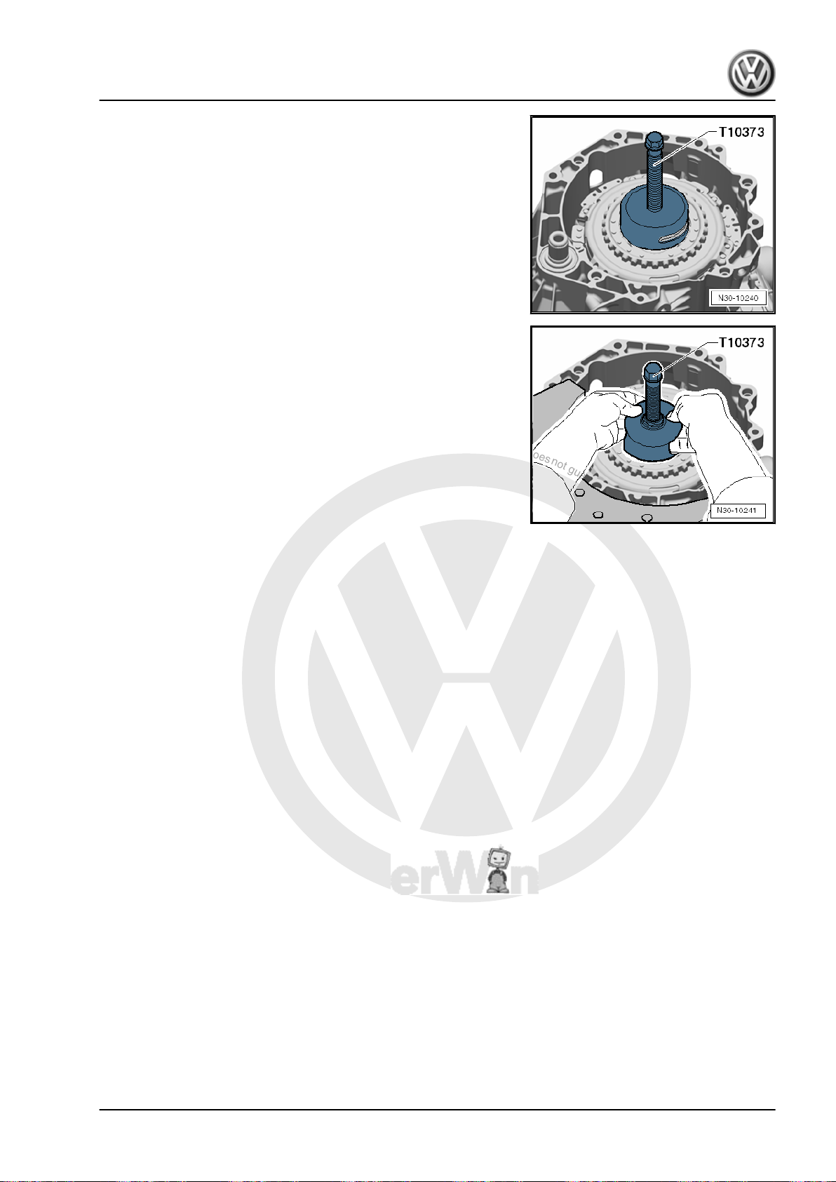
P
r
o
t
e
c
t
e
d
b
y
c
o
p
y
r
i
g
h
t
.
C
o
p
y
i
n
g
f
o
r
p
r
i
v
a
t
e
o
r
c
o
m
m
e
r
c
i
a
l
p
u
r
p
o
s
e
s
,
i
n
p
a
r
t
o
r
i
n
w
h
o
l
e
,
i
s
n
o
t
p
e
r
m
i
t
t
e
d
u
n
l
e
s
s
a
u
t
h
o
r
i
s
e
d
b
y
V
o
l
k
s
w
a
g
e
n
A
G
.
V
o
l
k
s
w
a
g
e
n
A
G
d
o
e
s
n
o
t
g
u
a
r
a
n
t
e
e
o
r
a
c
c
e
p
t
a
n
y
l
i
a
b
i
l
i
t
y
w
i
t
h
r
e
s
p
e
c
t
t
o
t
h
e
c
o
r
r
e
c
t
n
e
s
s
o
f
i
n
f
o
r
m
a
t
i
o
n
i
n
t
h
i
s
d
o
c
u
m
e
n
t
.
C
o
p
y
r
i
g
h
t
b
y
V
o
l
k
s
w
a
g
e
n
A
G
.
Direct Shift Gearbox - Edition 01.2016
Continuation for Removing the Locking Ring:
– Insert the Puller - Clutch - T10373- into the clutch and remove
the clutch.
– Remove the dual clutch together with the Puller - Clutch -
T10373- .
2.3 Dual Clutch, Installing
Special tools and workshop equipment required
♦ Support Bridge - T10323-
♦ Subframe Bushing Assembly Tool Kit -Assembly Tool 5 -
T10356/5- from the Subframe Bushing Assembly Tool Kit T10356-
♦ Puller - Clutch - T10373-
♦ Clutch Press Piece - T10376-
Jetta Hybrid 2013 ➤
2. Clutch 37
Page 42
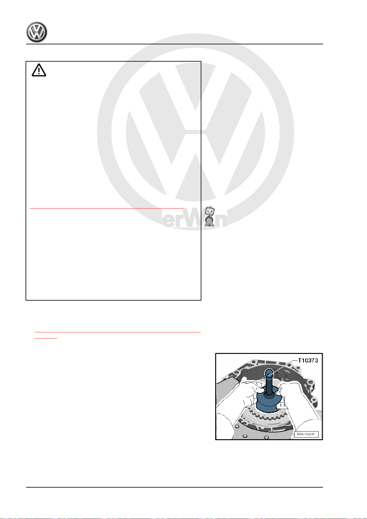
P
r
o
t
e
c
t
e
d
b
y
c
o
p
y
r
i
g
h
t
.
C
o
p
y
i
n
g
f
o
r
p
r
i
v
a
t
e
o
r
c
o
m
m
e
r
c
i
a
l
p
u
r
p
o
s
e
s
,
i
n
p
a
r
t
o
r
i
n
w
h
o
l
e
,
i
s
n
o
t
p
e
r
m
i
t
t
e
d
u
n
l
e
s
s
a
u
t
h
o
r
i
s
e
d
b
y
V
o
l
k
s
w
a
g
e
n
A
G
.
V
o
l
k
s
w
a
g
e
n
A
G
d
o
e
s
n
o
t
g
u
a
r
a
n
t
e
e
o
r
a
c
c
e
p
t
a
n
y
l
i
a
b
i
l
i
t
y
w
i
t
h
r
e
s
p
e
c
t
t
o
t
h
e
c
o
r
r
e
c
t
n
e
s
s
o
f
i
n
f
o
r
m
a
t
i
o
n
i
n
t
h
i
s
d
o
c
u
m
e
n
t
.
C
o
p
y
r
i
g
h
t
b
y
V
o
l
k
s
w
a
g
e
n
A
G
.
Jetta Hybrid 2013 ➤
Direct Shift Gearbox - Edition 01.2016
Installing
Caution
Danger of damaging the dual clutch and other components.
• The position of the engaging bearings must be adjusted
correctly.
Adjusting the engaging bearings can only be performed prior
to installing the dual clutch.
The position of the engaging bearing must be adjusted after
completing the following:
♦ The dual clutch was replaced.
♦ The engaging levers were replaced.
♦ The ball stud for the “K 2” engaging lever was replaced.
♦ The engaging bearings were replaced.
It is necessary to adjust the position of the “K 1 and K 2” en‐
gaging bearings first if one of the above mentioned procedures
was performed. Refer to
⇒ “1.3 Clutch Engaging Mechanism, Adjusting”, page 19 .
Continue with assembling only when the adjustment is correct.
The removed shims can be used again if no new parts were
installed.
Only one shim per engaging bearing can be installed.
• Clutch components must have no oil or grease on them
when being installed.
Danger of causing damage to the dual clutch adjusting tool.
♦ The dual clutch is self-adjusting. Vibrations can affect the
adjusting tool. Be careful not to drop the dual clutch into
the transmission when installing.
Requirement:
• The clutch engaging mechanism is installed. Refer to
⇒ “1.2 Clutch Engaging Mechanism, Removing and Installing”,
page 16 .
– Turn back the spindle on the Puller - Clutch - T10373- .
– Install the dual clutch into the transmission using Puller -
Clutch - T10373- , as illustrated.
38 Rep. Gr.30 - Clutch
Page 43
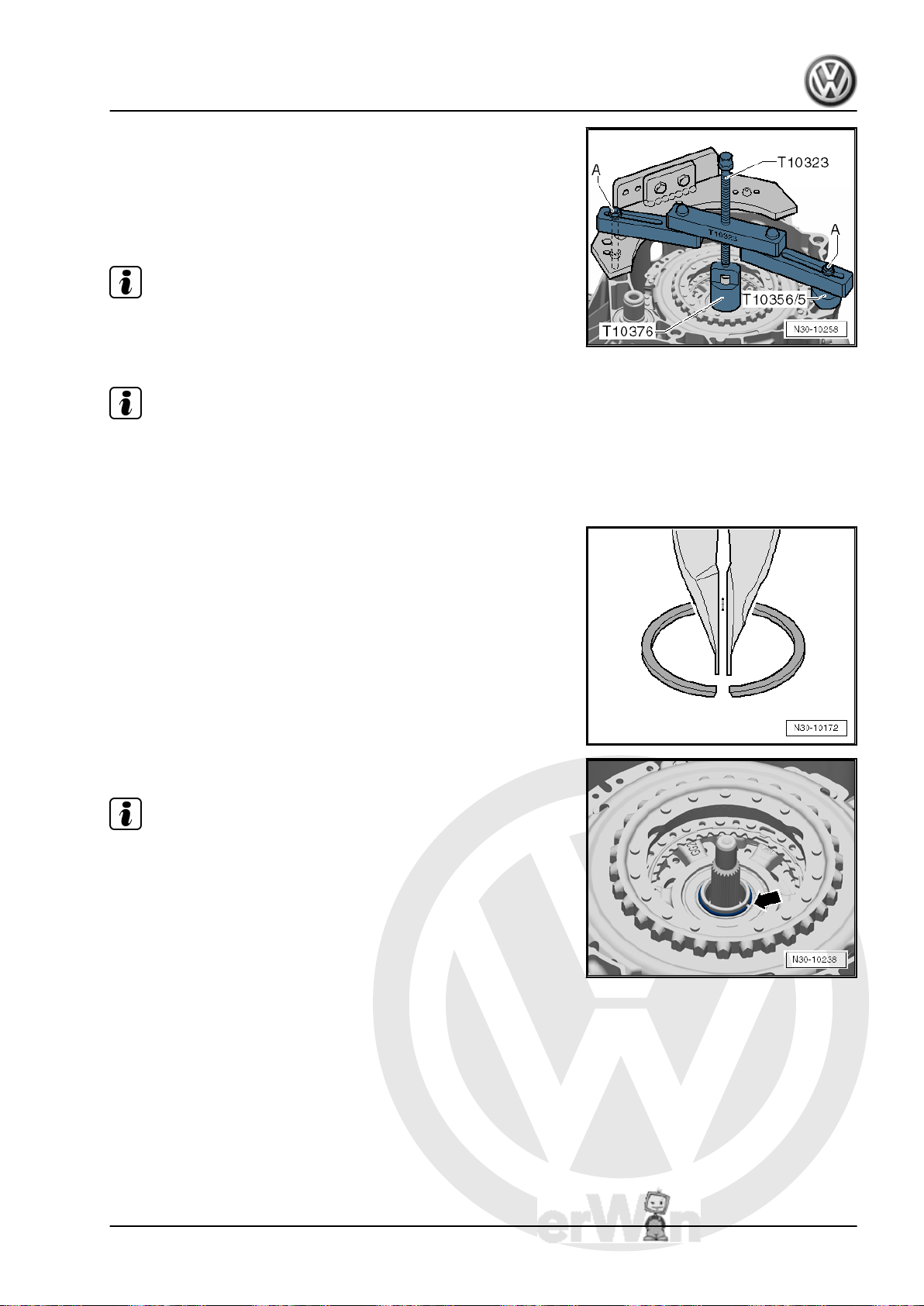
P
r
o
t
e
c
t
e
d
b
y
c
o
p
y
r
i
g
h
t
.
C
o
p
y
i
n
g
f
o
r
p
r
i
v
a
t
e
o
r
c
o
m
m
e
r
c
i
a
l
p
u
r
p
o
s
e
s
,
i
n
p
a
r
t
o
r
i
n
w
h
o
l
e
,
i
s
n
o
t
p
e
r
m
i
t
t
e
d
u
n
l
e
s
s
a
u
t
h
o
r
i
s
e
d
b
y
V
o
l
k
s
w
a
g
e
n
A
G
.
V
o
l
k
s
w
a
g
e
n
A
G
d
o
e
s
n
o
t
g
u
a
r
a
n
t
e
e
o
r
a
c
c
e
p
t
a
n
y
l
i
a
b
i
l
i
t
y
w
i
t
h
r
e
s
p
e
c
t
t
o
t
h
e
c
o
r
r
e
c
t
n
e
s
s
o
f
i
n
f
o
r
m
a
t
i
o
n
i
n
t
h
i
s
d
o
c
u
m
e
n
t
.
C
o
p
y
r
i
g
h
t
b
y
V
o
l
k
s
w
a
g
e
n
A
G
.
Direct Shift Gearbox - Edition 01.2016
– Position the Support Bridge - T1032- parallel to the transmis‐
sion flange, as illustrated.
– If necessary, even out the gaps, for example, using Subframe
Bushing Assembly Tool Kit -Assembly Tool 5 - T10356/5- from
the Subframe Bushing Assembly Tool Kit - T10356- .
– Tighten the bolts -A- hand-tight.
Note
Secure the bolts -A- with a nut, if needed.
– Push on the dual clutch until it stops.
Note
Keep hand on the dual clutch while pressing it on. A slight »vi‐
brating« should be felt. Vibrating means the dual clutch is being
pushed onto its press-fit. It can also be felt when the dual clutch
has reached its stop.
Jetta Hybrid 2013 ➤
– Hold the new locking ring with locking ring pliers, as illustrated.
• Installed position: narrow ends of the locking ring at the top.
– Install the circlip -arrow-
Note
The dual clutch is not pressed correctly on the stop if the locking
ring cannot be installed.
2. Clutch 39
Page 44
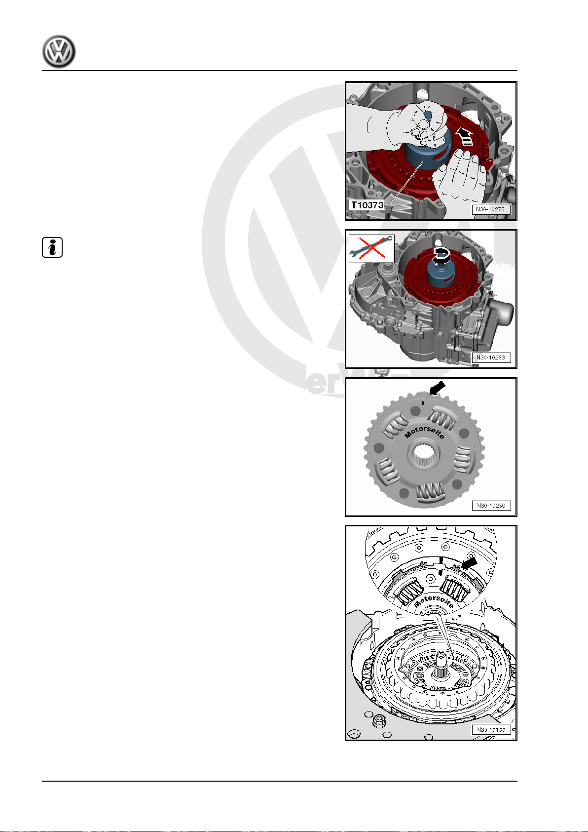
P
r
o
t
e
c
t
e
d
b
y
c
o
p
y
r
i
g
h
t
.
C
o
p
y
i
n
g
f
o
r
p
r
i
v
a
t
e
o
r
c
o
m
m
e
r
c
i
a
l
p
u
r
p
o
s
e
s
,
i
n
p
a
r
t
o
r
i
n
w
h
o
l
e
,
i
s
n
o
t
p
e
r
m
i
t
t
e
d
u
n
l
e
s
s
a
u
t
h
o
r
i
s
e
d
b
y
V
o
l
k
s
w
a
g
e
n
A
G
.
V
o
l
k
s
w
a
g
e
n
A
G
d
o
e
s
n
o
t
g
u
a
r
a
n
t
e
e
o
r
a
c
c
e
p
t
a
n
y
l
i
a
b
i
l
i
t
y
w
i
t
h
r
e
s
p
e
c
t
t
o
t
h
e
c
o
r
r
e
c
t
n
e
s
s
o
f
i
n
f
o
r
m
a
t
i
o
n
i
n
t
h
i
s
d
o
c
u
m
e
n
t
.
C
o
p
y
r
i
g
h
t
b
y
V
o
l
k
s
w
a
g
e
n
A
G
.
Jetta Hybrid 2013 ➤
Direct Shift Gearbox - Edition 01.2016
– Turn the dual clutch against the Puller - Clutch - T10373- by
hand without using any other tools so that it can move into its
working position in direction of -arrow-.
Note
♦
The dual clutch sits on the stop at the bottom of the input shaft.
This is not its optimal position.
♦
The dual clutch should be pulled up just far enough until it
touches the locking ring.
♦
Only turn it by hand. This way the dual clutch slides against
the locking ring. Do not use any other tool.
– Install the hub.
• The hub as a single »large tooth« -arrow- and fits in only one
position.
• The large tooth has a marking on the engine side.
– Insert the locking ring -arrow-.
• The end of the locking ring must face the »nose« on the dual
clutch.
40 Rep. Gr.30 - Clutch
Page 45
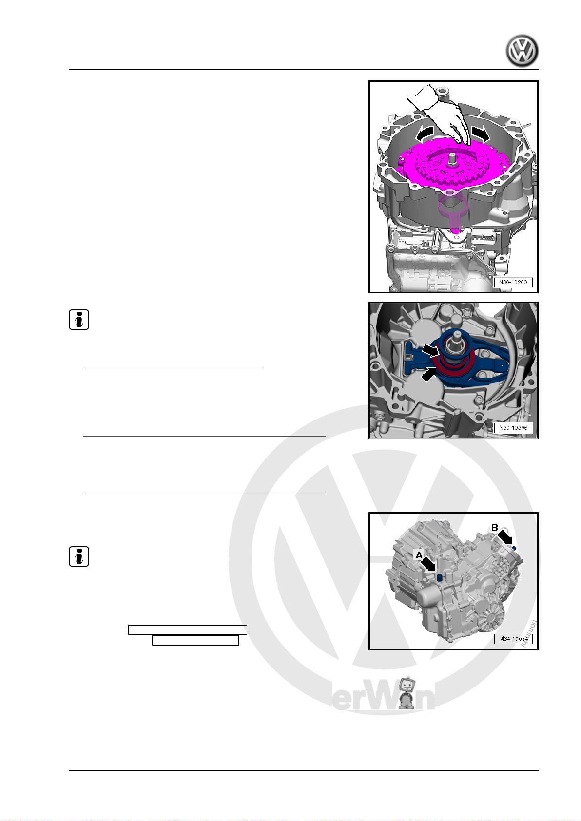
P
r
o
t
e
c
t
e
d
b
y
c
o
p
y
r
i
g
h
t
.
C
o
p
y
i
n
g
f
o
r
p
r
i
v
a
t
e
o
r
c
o
m
m
e
r
c
i
a
l
p
u
r
p
o
s
e
s
,
i
n
p
a
r
t
o
r
i
n
w
h
o
l
e
,
i
s
n
o
t
p
e
r
m
i
t
t
e
d
u
n
l
e
s
s
a
u
t
h
o
r
i
s
e
d
b
y
V
o
l
k
s
w
a
g
e
n
A
G
.
V
o
l
k
s
w
a
g
e
n
A
G
d
o
e
s
n
o
t
g
u
a
r
a
n
t
e
e
o
r
a
c
c
e
p
t
a
n
y
l
i
a
b
i
l
i
t
y
w
i
t
h
r
e
s
p
e
c
t
t
o
t
h
e
c
o
r
r
e
c
t
n
e
s
s
o
f
i
n
f
o
r
m
a
t
i
o
n
i
n
t
h
i
s
d
o
c
u
m
e
n
t
.
C
o
p
y
r
i
g
h
t
b
y
V
o
l
k
s
w
a
g
e
n
A
G
.
Direct Shift Gearbox - Edition 01.2016
– Turn the dual clutch by hand. The dual clutch should turn with‐
out any problem.
Note
Jetta Hybrid 2013 ➤
♦
Remove the dual clutch if it is difficult to turn or if it grinds
against the clutch plates while being turned. Refer to
⇒ “2.2 DSG® Clutch, Removing”, page 33 .
♦
Check the installed position of the shims -arrows-.
♦
The shims must fit correctly and must not be damaged.
♦
It is possible there was a calculation error. Check the meas‐
urements one more time. Refer to
⇒ “1.3 Clutch Engaging Mechanism, Adjusting”, page 19 .
♦
If there was no error, then it is possible the dual clutch shifted
during transportation/assembly. In this case it is necessary to
install a new dual clutch. Then it is necessary to adjust the
position of the engaging bearing again. Refer to
⇒ “1.3 Clutch Engaging Mechanism, Adjusting”, page 19 .
– Remove both plugs and install the vent caps
-arrow A and B-.
Note
The vent cap -arrow A- on the Mechatronic will get damaged when
being removed and must be replaced.
– Dispose of any extra shims.
– Perform a Complete Basic Setting using the Vehicle Di‐
agnostic Tester Guided Functions
mission.
2.4 Input Shaft Seal, Replacing
Replace the seal for the outer input shaft.
Special tools and workshop equipment required
after installing the trans‐
♦ Press Piece - 60mm - VW415A-
♦ Puller - Crankshaft/Power Steering Seal - T20143/2-
2. Clutch 41
Page 46
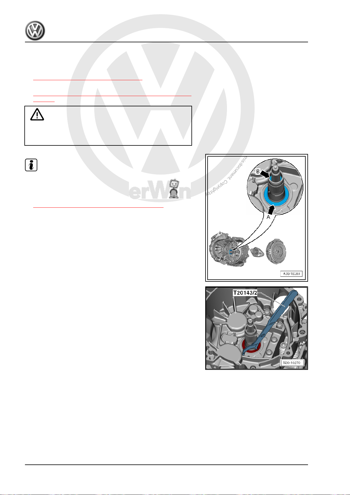
P
r
o
t
e
c
t
e
d
b
y
c
o
p
y
r
i
g
h
t
.
C
o
p
y
i
n
g
f
o
r
p
r
i
v
a
t
e
o
r
c
o
m
m
e
r
c
i
a
l
p
u
r
p
o
s
e
s
,
i
n
p
a
r
t
o
r
i
n
w
h
o
l
e
,
i
s
n
o
t
p
e
r
m
i
t
t
e
d
u
n
l
e
s
s
a
u
t
h
o
r
i
s
e
d
b
y
V
o
l
k
s
w
a
g
e
n
A
G
.
V
o
l
k
s
w
a
g
e
n
A
G
d
o
e
s
n
o
t
g
u
a
r
a
n
t
e
e
o
r
a
c
c
e
p
t
a
n
y
l
i
a
b
i
l
i
t
y
w
i
t
h
r
e
s
p
e
c
t
t
o
t
h
e
c
o
r
r
e
c
t
n
e
s
s
o
f
i
n
f
o
r
m
a
t
i
o
n
i
n
t
h
i
s
d
o
c
u
m
e
n
t
.
C
o
p
y
r
i
g
h
t
b
y
V
o
l
k
s
w
a
g
e
n
A
G
.
Jetta Hybrid 2013 ➤
Direct Shift Gearbox - Edition 01.2016
♦ Sealing Grease - G 052 128 A1-
Procedure
• The dual clutch is removed. Refer to
⇒ “2.2 DSG® Clutch, Removing”, page 33 .
• The clutch engaging mechanism is removed. Refer to
⇒ “1.2 Clutch Engaging Mechanism, Removing and Installing”,
page 16 .
Caution
Danger of damaging the dual clutch and other components.
• Replace the dual clutch if it is covered with oil.
Note
♦
There are 2 seals in the transmission on the clutch side.
♦
Input shaft seal -arrow A-.
♦
Inner input shaft seal -arrow B-. Refer to
⇒ “2.5 Inner Input Shaft Seal, Replacing”, page 43 .
♦
It is possible to replace both seals without disassembling the
transmission. It is not necessary to adjust the clutch engaging
mechanism if only the seals are being replaced.
– Pry out the outer seal.
42 Rep. Gr.30 - Clutch
Page 47
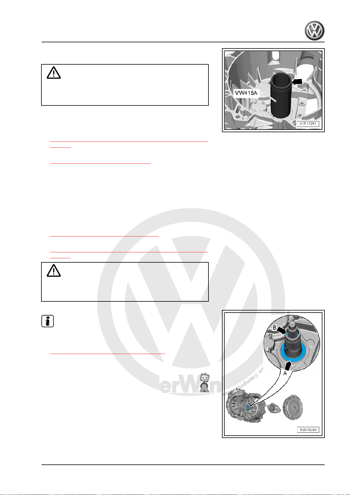
P
r
o
t
e
c
t
e
d
b
y
c
o
p
y
r
i
g
h
t
.
C
o
p
y
i
n
g
f
o
r
p
r
i
v
a
t
e
o
r
c
o
m
m
e
r
c
i
a
l
p
u
r
p
o
s
e
s
,
i
n
p
a
r
t
o
r
i
n
w
h
o
l
e
,
i
s
n
o
t
p
e
r
m
i
t
t
e
d
u
n
l
e
s
s
a
u
t
h
o
r
i
s
e
d
b
y
V
o
l
k
s
w
a
g
e
n
A
G
.
V
o
l
k
s
w
a
g
e
n
A
G
d
o
e
s
n
o
t
g
u
a
r
a
n
t
e
e
o
r
a
c
c
e
p
t
a
n
y
l
i
a
b
i
l
i
t
y
w
i
t
h
r
e
s
p
e
c
t
t
o
t
h
e
c
o
r
r
e
c
t
n
e
s
s
o
f
i
n
f
o
r
m
a
t
i
o
n
i
n
t
h
i
s
d
o
c
u
m
e
n
t
.
C
o
p
y
r
i
g
h
t
b
y
V
o
l
k
s
w
a
g
e
n
A
G
.
Direct Shift Gearbox - Edition 01.2016
– Install the new seal for the outer input shaft with a plastic ham‐
mer so that it is flush with the clutch housing, as illustrated.
Caution
Install the seal flush with the clutch housing so that the oil bore
behind it is not sealed. Otherwise the outer input shaft ball
bearing will not have enough oil.
• The Press Piece - 60mm - VW415A- offset points upward
-arrow-.
– Install the clutch engaging mechanism. Refer to
⇒ “1.2 Clutch Engaging Mechanism, Removing and Installing”,
page 16 .
– Install the dual clutch. Refer to
⇒ “2.3 Dual Clutch, Installing”, page 37 .
2.5 Inner Input Shaft Seal, Replacing
Special tools and workshop equipment required
♦ Puller - Shaft Seal - T10420-
♦ Seal Installer - Shaft Seal - T10421-
Procedure
• The dual clutch is removed. Refer to
⇒ “2.2 DSG® Clutch, Removing”, page 33 .
• The clutch engaging mechanism is removed. Refer to
⇒ “1.2 Clutch Engaging Mechanism, Removing and Installing”,
page 16 .
Danger of damaging the dual clutch and other components.
• Replace the dual clutch if it is covered with oil.
Note
♦
There are 2 seals in the transmission on the clutch side.
♦
Input shaft seal -arrow A-. Refer to
Caution
⇒ “2.4 Input Shaft Seal, Replacing”, page 41 .
♦
Inner input shaft seal -arrow B-.
♦
It is possible to replace both seals without disassembling the
transmission. It is not necessary to adjust the clutch engaging
mechanism if only the seals are being replaced.
Jetta Hybrid 2013 ➤
2. Clutch 43
Page 48
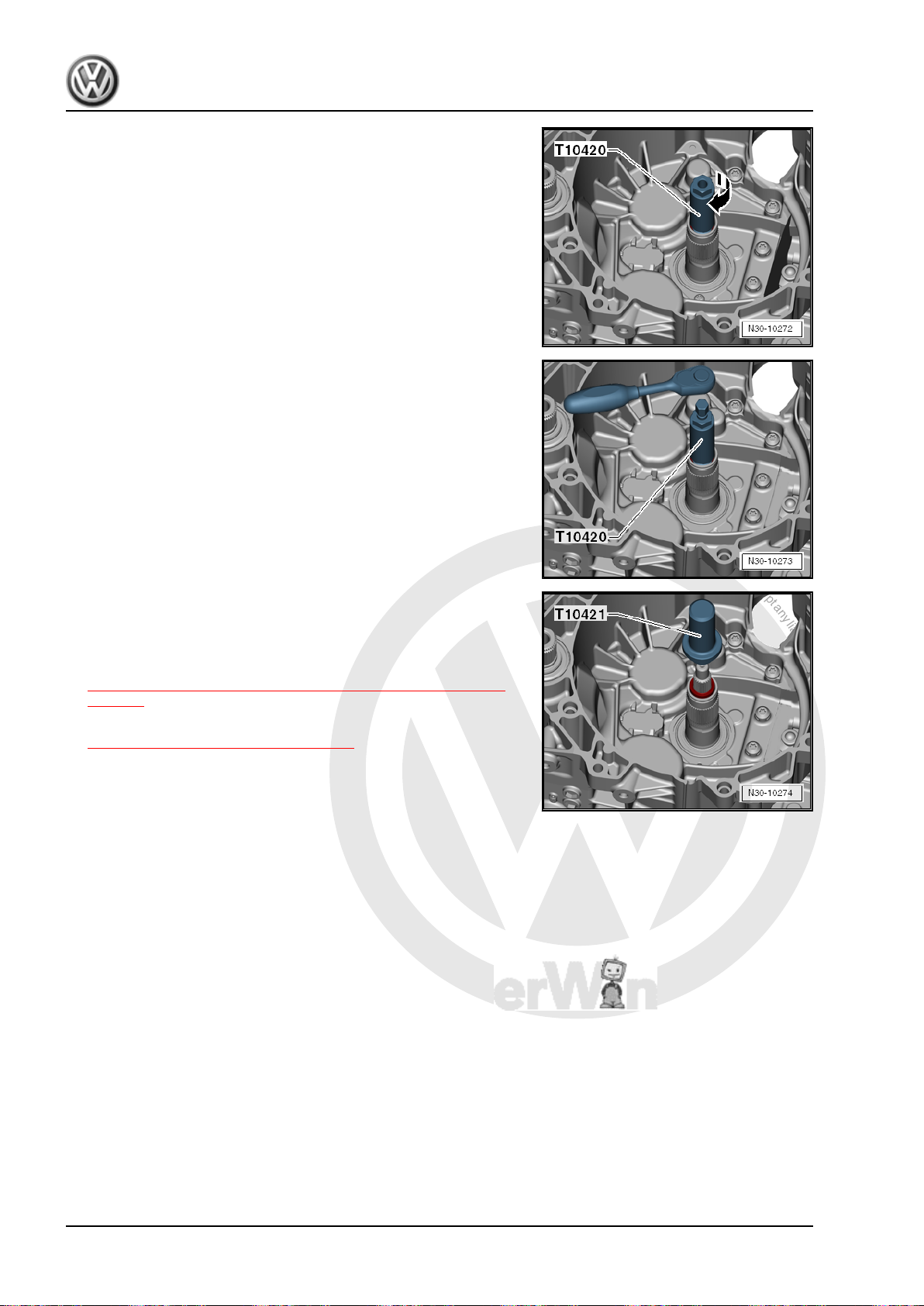
P
r
o
t
e
c
t
e
d
b
y
c
o
p
y
r
i
g
h
t
.
C
o
p
y
i
n
g
f
o
r
p
r
i
v
a
t
e
o
r
c
o
m
m
e
r
c
i
a
l
p
u
r
p
o
s
e
s
,
i
n
p
a
r
t
o
r
i
n
w
h
o
l
e
,
i
s
n
o
t
p
e
r
m
i
t
t
e
d
u
n
l
e
s
s
a
u
t
h
o
r
i
s
e
d
b
y
V
o
l
k
s
w
a
g
e
n
A
G
.
V
o
l
k
s
w
a
g
e
n
A
G
d
o
e
s
n
o
t
g
u
a
r
a
n
t
e
e
o
r
a
c
c
e
p
t
a
n
y
l
i
a
b
i
l
i
t
y
w
i
t
h
r
e
s
p
e
c
t
t
o
t
h
e
c
o
r
r
e
c
t
n
e
s
s
o
f
i
n
f
o
r
m
a
t
i
o
n
i
n
t
h
i
s
d
o
c
u
m
e
n
t
.
C
o
p
y
r
i
g
h
t
b
y
V
o
l
k
s
w
a
g
e
n
A
G
.
Jetta Hybrid 2013 ➤
Direct Shift Gearbox - Edition 01.2016
– Remove the Puller - Shaft Seal - T10420- spindle.
– Install the Puller - Shaft Seal - T10420- into the inner input
shaft seal while pressing on the Puller - Shaft Seal - T10420- .
The Puller - Shaft Seal - T10420- will jam the seal when it is being
turned
– Turn the Puller - Shaft Seal - T10420- just enough until the
seal begins to turn with it.
– Then install the spindle into the Puller - Shaft Seal - T10420- .
– Remove the seal using the spindle.
– Install the new seal up to the edge of the tool using Seal In‐
staller - Shaft Seal - T10421- .
Seal Installation Depth: 17.5 ± 0.2 mm
– Install the clutch engaging mechanism. Refer to
⇒ “1.2 Clutch Engaging Mechanism, Removing and Installing”,
page 16 .
– Install the dual clutch. Refer to
⇒ “2.3 Dual Clutch, Installing”, page 37 .
44 Rep. Gr.30 - Clutch
Page 49
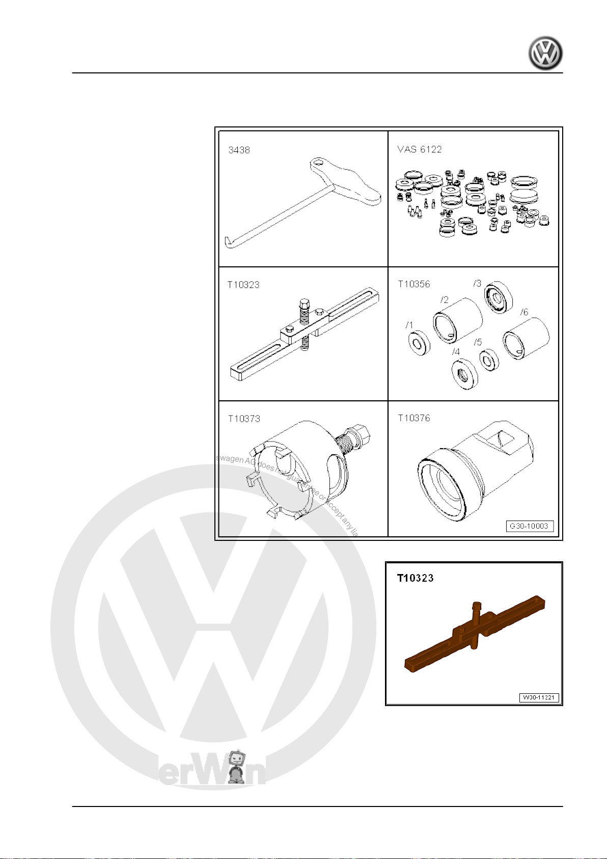
P
r
o
t
e
c
t
e
d
b
y
c
o
p
y
r
i
g
h
t
.
C
o
p
y
i
n
g
f
o
r
p
r
i
v
a
t
e
o
r
c
o
m
m
e
r
c
i
a
l
p
u
r
p
o
s
e
s
,
i
n
p
a
r
t
o
r
i
n
w
h
o
l
e
,
i
s
n
o
t
p
e
r
m
i
t
t
e
d
u
n
l
e
s
s
a
u
t
h
o
r
i
s
e
d
b
y
V
o
l
k
s
w
a
g
e
n
A
G
.
V
o
l
k
s
w
a
g
e
n
A
G
d
o
e
s
n
o
t
g
u
a
r
a
n
t
e
e
o
r
a
c
c
e
p
t
a
n
y
l
i
a
b
i
l
i
t
y
w
i
t
h
r
e
s
p
e
c
t
t
o
t
h
e
c
o
r
r
e
c
t
n
e
s
s
o
f
i
n
f
o
r
m
a
t
i
o
n
i
n
t
h
i
s
d
o
c
u
m
e
n
t
.
C
o
p
y
r
i
g
h
t
b
y
V
o
l
k
s
w
a
g
e
n
A
G
.
3 Special Tools
Special tools and workshop
equipment required
♦ T-Handle Hook - 3438-
♦ Engine Bung Set -
VAS6122-
♦ Support Bridge - T10323-
♦ Subframe Bushing Assem‐
bly Tool Kit -Assembly Tool
5 - T10356/5- from the Sub‐
frame Bushing Assembly
Tool Kit - T10356-
♦ Puller - Clutch - T10373-
♦ Clutch Press Piece -
T10376-
♦ Protective Cap - 0AM 325
120 A- quantity 1 and Pro‐
tective Cap - 02M 409 120quantity 1, as an alternative
to the Engine Bung Set VAS6122-
Jetta Hybrid 2013 ➤
Direct Shift Gearbox - Edition 01.2016
Support Bridge - T10323-
3. Special Tools 45
Page 50
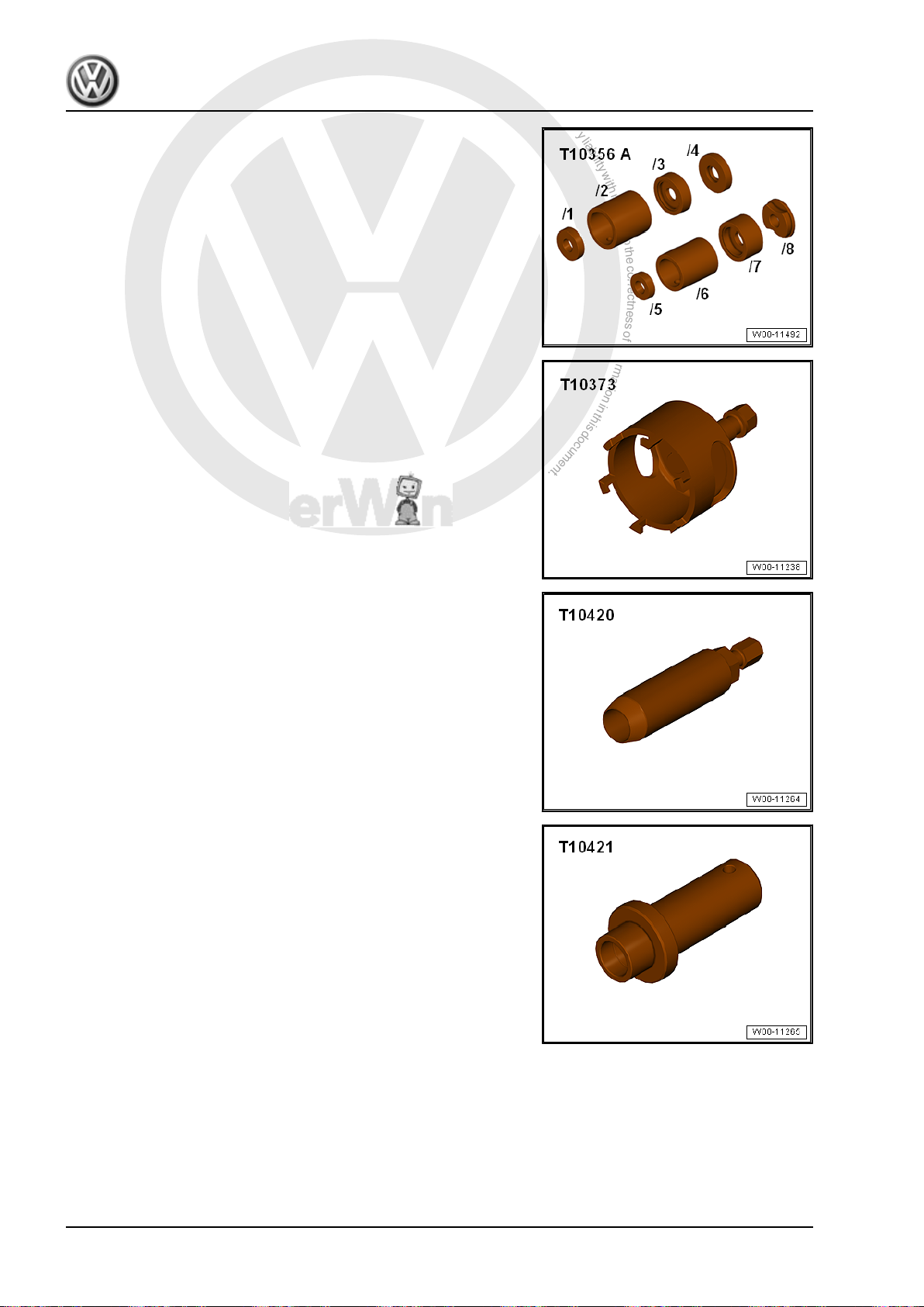
P
r
o
t
e
c
t
e
d
b
y
c
o
p
y
r
i
g
h
t
.
C
o
p
y
i
n
g
f
o
r
p
r
i
v
a
t
e
o
r
c
o
m
m
e
r
c
i
a
l
p
u
r
p
o
s
e
s
,
i
n
p
a
r
t
o
r
i
n
w
h
o
l
e
,
i
s
n
o
t
p
e
r
m
i
t
t
e
d
u
n
l
e
s
s
a
u
t
h
o
r
i
s
e
d
b
y
V
o
l
k
s
w
a
g
e
n
A
G
.
V
o
l
k
s
w
a
g
e
n
A
G
d
o
e
s
n
o
t
g
u
a
r
a
n
t
e
e
o
r
a
c
c
e
p
t
a
n
y
l
i
a
b
i
l
i
t
y
w
i
t
h
r
e
s
p
e
c
t
t
o
t
h
e
c
o
r
r
e
c
t
n
e
s
s
o
f
i
n
f
o
r
m
a
t
i
o
n
i
n
t
h
i
s
d
o
c
u
m
e
n
t
.
C
o
p
y
r
i
g
h
t
b
y
V
o
l
k
s
w
a
g
e
n
A
G
.
Jetta Hybrid 2013 ➤
Direct Shift Gearbox - Edition 01.2016
Subframe Bushing Assembly Tool Kit -Assembly Tool 5 T10356/5- from the Subframe Bushing Assembly Tool Kit T10356-
Puller - Clutch - T10373-
Puller - Shaft Seal - T10420-
Seal Installer - Shaft Seal - T10421-
46 Rep. Gr.30 - Clutch
Page 51
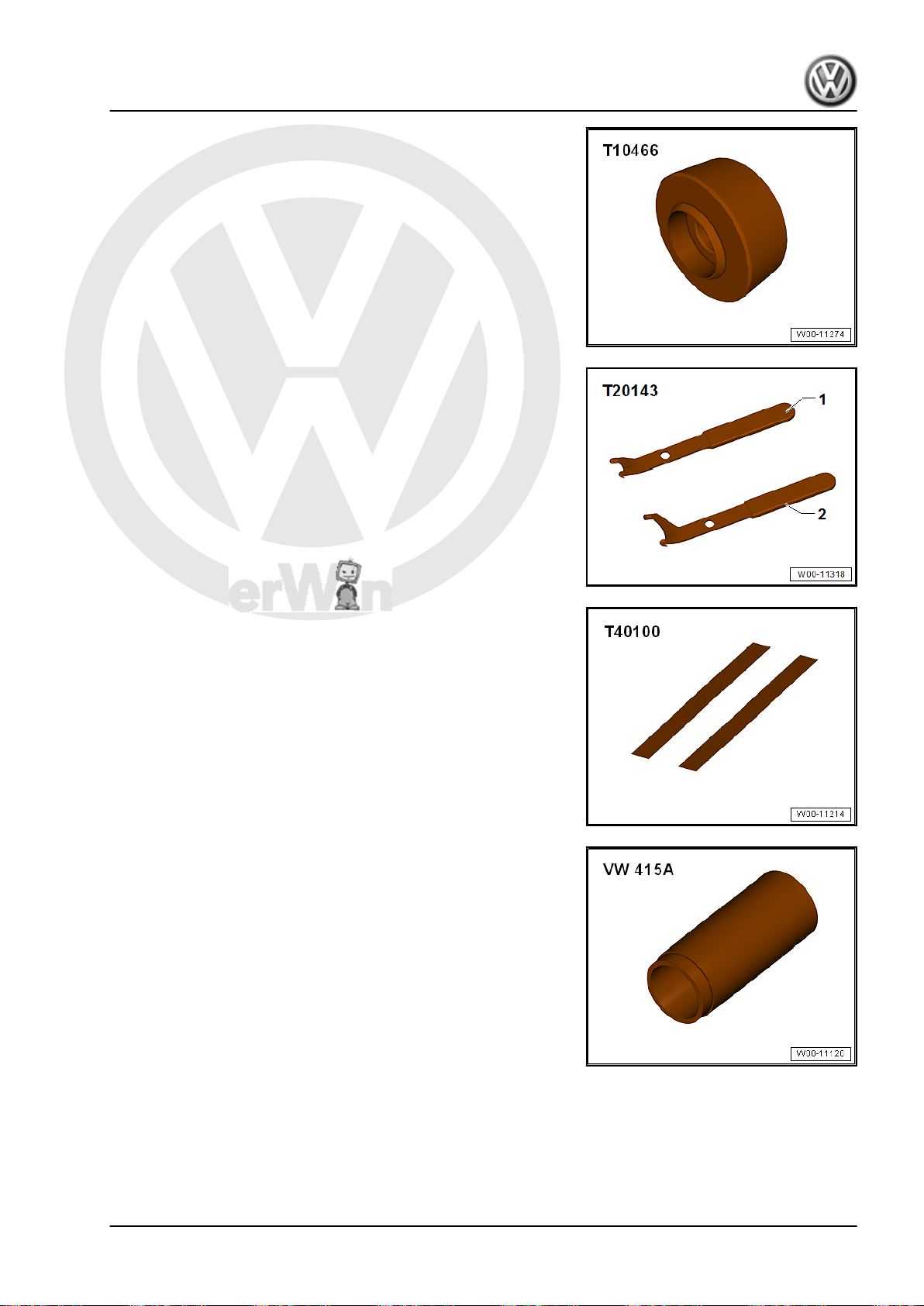
P
r
o
t
e
c
t
e
d
b
y
c
o
p
y
r
i
g
h
t
.
C
o
p
y
i
n
g
f
o
r
p
r
i
v
a
t
e
o
r
c
o
m
m
e
r
c
i
a
l
p
u
r
p
o
s
e
s
,
i
n
p
a
r
t
o
r
i
n
w
h
o
l
e
,
i
s
n
o
t
p
e
r
m
i
t
t
e
d
u
n
l
e
s
s
a
u
t
h
o
r
i
s
e
d
b
y
V
o
l
k
s
w
a
g
e
n
A
G
.
V
o
l
k
s
w
a
g
e
n
A
G
d
o
e
s
n
o
t
g
u
a
r
a
n
t
e
e
o
r
a
c
c
e
p
t
a
n
y
l
i
a
b
i
l
i
t
y
w
i
t
h
r
e
s
p
e
c
t
t
o
t
h
e
c
o
r
r
e
c
t
n
e
s
s
o
f
i
n
f
o
r
m
a
t
i
o
n
i
n
t
h
i
s
d
o
c
u
m
e
n
t
.
C
o
p
y
r
i
g
h
t
b
y
V
o
l
k
s
w
a
g
e
n
A
G
.
Jetta Hybrid 2013 ➤
♦ Gauge - Clutch Bearings - T10466-
♦ Puller - Crankshaft/Power Steering Seal - T20143/2-
♦ Ruler (2 pc.) - T40100-
Direct Shift Gearbox - Edition 01.2016
♦ Press Piece - 60mm - VW415A-
♦ Digital Depth Gauge - 300mm - VAS6594-
3. Special Tools 47
Page 52
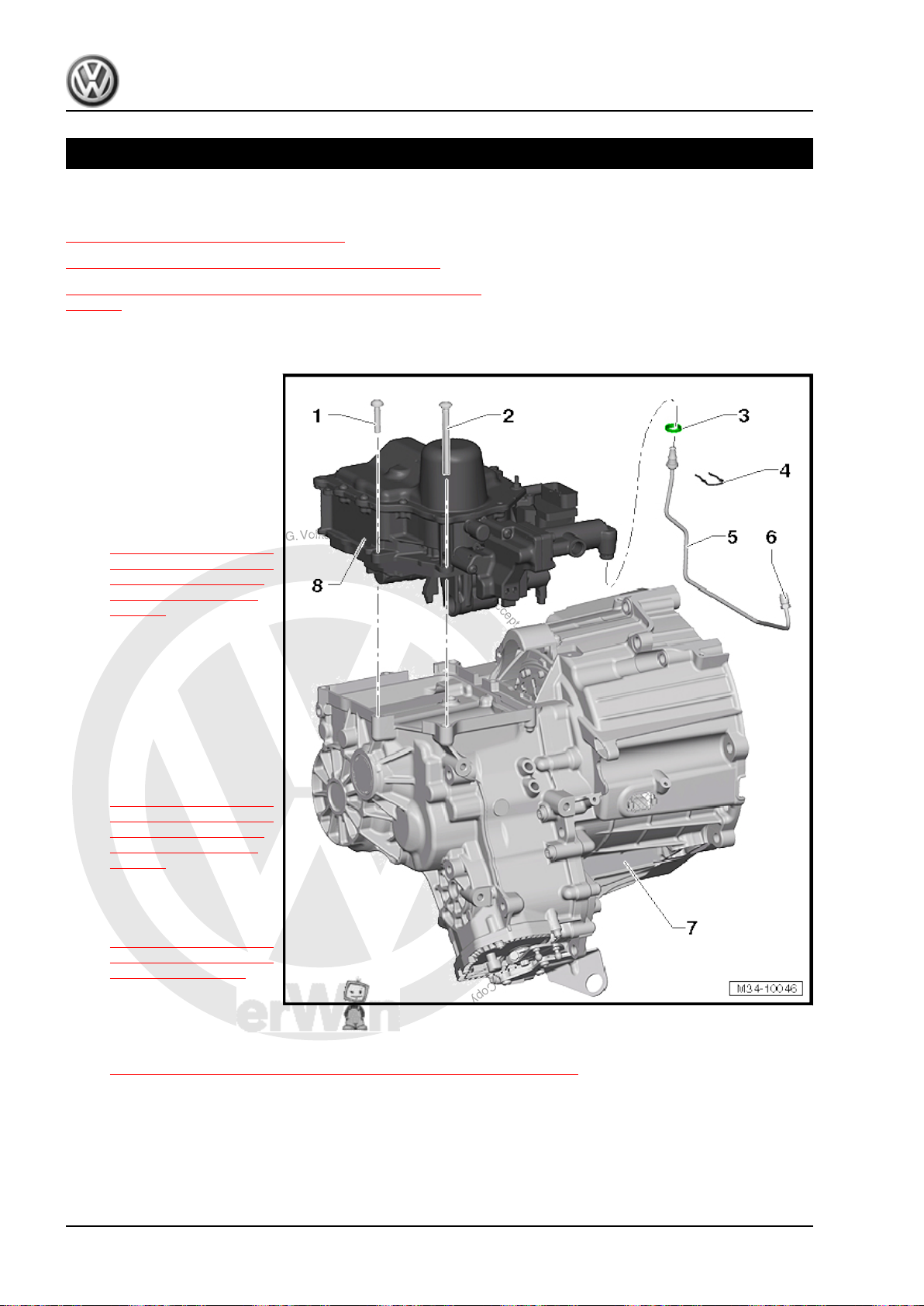
P
r
o
t
e
c
t
e
d
b
y
c
o
p
y
r
i
g
h
t
.
C
o
p
y
i
n
g
f
o
r
p
r
i
v
a
t
e
o
r
c
o
m
m
e
r
c
i
a
l
p
u
r
p
o
s
e
s
,
i
n
p
a
r
t
o
r
i
n
w
h
o
l
e
,
i
s
n
o
t
p
e
r
m
i
t
t
e
d
u
n
l
e
s
s
a
u
t
h
o
r
i
s
e
d
b
y
V
o
l
k
s
w
a
g
e
n
A
G
.
V
o
l
k
s
w
a
g
e
n
A
G
d
o
e
s
n
o
t
g
u
a
r
a
n
t
e
e
o
r
a
c
c
e
p
t
a
n
y
l
i
a
b
i
l
i
t
y
w
i
t
h
r
e
s
p
e
c
t
t
o
t
h
e
c
o
r
r
e
c
t
n
e
s
s
o
f
i
n
f
o
r
m
a
t
i
o
n
i
n
t
h
i
s
d
o
c
u
m
e
n
t
.
C
o
p
y
r
i
g
h
t
b
y
V
o
l
k
s
w
a
g
e
n
A
G
.
Jetta Hybrid 2013 ➤
Direct Shift Gearbox - Edition 01.2016
34 – Controls, Housing
1 Mechatronic
⇒ “1.1 Overview - Mechatronic”, page 48
⇒ “1.2 Mechatronic, Removing and Installing”, page 50
⇒ “1.3 Mechatronic, Moving into Removal Position by Hand”,
page 69
1.1 Overview - Mechatronic
1 - Bolt
❑ For attaching the DSG
Transmission Mecha‐
tronic - J743- to the
transmission housing
❑ Quantity: 3, M8 x 35
❑ Replace after removing
❑ Tightening specification
and sequence. Refer to
⇒ Fig. ““ DSG Transmis‐
sion Mechatronic -J743-
- Tightening Specifica‐
tion and Sequence”“ ,
page 50
2 - Bolt
3 - O-Ring
❑ For attaching the DSG
Transmission Mecha‐
tronic - J743- to the
transmission housing
❑ Quantity: 4, M8 x 90
❑ Replace after removing
❑ Tightening specification
and sequence. Refer to
⇒ Fig. ““ DSG Transmis‐
sion Mechatronic -J743-
- Tightening Specifica‐
tion and Sequence”“ ,
page 50
❑ Identification: Color:
green
⇒ Fig. ““O-Ring Installed
Position and Color Iden‐
tification”“ , page 49
❑ Replace if damaged
❑ Only available with hy‐
draulic line. Refer to the Parts Catalog.
❑ Install on the hydraulic line connection
⇒ Fig. ““O-Ring Installed Position and Color Identification”“ , page 49
❑ Install with hydraulic fluid
4 - Clamp
❑ Remove in order to remove and install the hydraulic line clamp
5 - Hydraulic Line
❑ Close the connections with new plugs from the Repair Kit - 5C0 998 152- . Refer to the Parts Catalog.
48 Rep. Gr.34 - Controls, Housing
Page 53
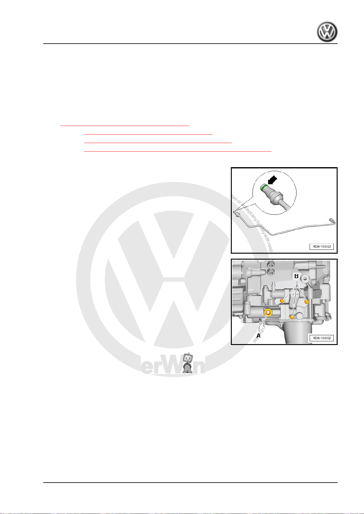
P
r
o
t
e
c
t
e
d
b
y
c
o
p
y
r
i
g
h
t
.
C
o
p
y
i
n
g
f
o
r
p
r
i
v
a
t
e
o
r
c
o
m
m
e
r
c
i
a
l
p
u
r
p
o
s
e
s
,
i
n
p
a
r
t
o
r
i
n
w
h
o
l
e
,
i
s
n
o
t
p
e
r
m
i
t
t
e
d
u
n
l
e
s
s
a
u
t
h
o
r
i
s
e
d
b
y
V
o
l
k
s
w
a
g
e
n
A
G
.
V
o
l
k
s
w
a
g
e
n
A
G
d
o
e
s
n
o
t
g
u
a
r
a
n
t
e
e
o
r
a
c
c
e
p
t
a
n
y
l
i
a
b
i
l
i
t
y
w
i
t
h
r
e
s
p
e
c
t
t
o
t
h
e
c
o
r
r
e
c
t
n
e
s
s
o
f
i
n
f
o
r
m
a
t
i
o
n
i
n
t
h
i
s
d
o
c
u
m
e
n
t
.
C
o
p
y
r
i
g
h
t
b
y
V
o
l
k
s
w
a
g
e
n
A
G
.
Direct Shift Gearbox - Edition 01.2016
❑ Comes with O-ring.
6 - Bolt
❑ 18 Nm
❑ For the hydraulic line to the engine
7 - Transmission
8 - DSG Transmission Mechatronic - J743-
❑ With valve block
❑ Do not remove the valve block from the Mechatronic . Refer to
⇒ Fig. ““Valve Block on Mechatronic”“ , page 49 .
❑ Refer to ⇒ “2.4 Mechatronic Safety Precautions”, page 3
❑ Refer to ⇒ “1.2 Mechatronic, Removing and Installing”, page 50
❑ Refer to ⇒ “1.3 Mechatronic, Moving into Removal Position by Hand”, page 69
O-Ring Installed Position and Color Identification
• The O-ring -arrow- must be green. It can be used with hy‐
draulic fluid. Do not use any other O-ring.
Valve Block on Mechatronic
• Do not open the bolt -A- and bolts -B- for the valve block on
the Mechatronic.
• If bolt and washer -A- is missing from new Mechatronic, trans‐
fer bolt and washer from old Mechatronic to new Mechatronic.
Torque bolt -A- to 15 Nm.
Jetta Hybrid 2013 ➤
1. Mechatronic 49
Page 54
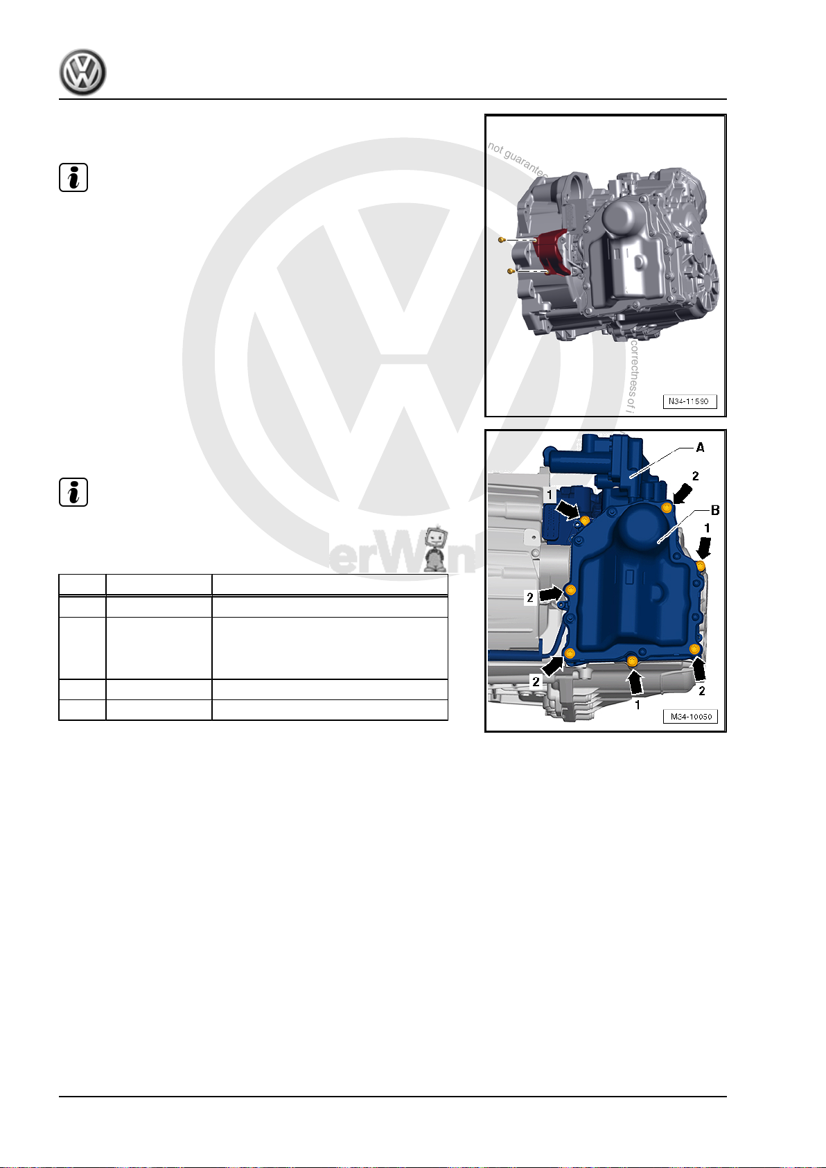
P
r
o
t
e
c
t
e
d
b
y
c
o
p
y
r
i
g
h
t
.
C
o
p
y
i
n
g
f
o
r
p
r
i
v
a
t
e
o
r
c
o
m
m
e
r
c
i
a
l
p
u
r
p
o
s
e
s
,
i
n
p
a
r
t
o
r
i
n
w
h
o
l
e
,
i
s
n
o
t
p
e
r
m
i
t
t
e
d
u
n
l
e
s
s
a
u
t
h
o
r
i
s
e
d
b
y
V
o
l
k
s
w
a
g
e
n
A
G
.
V
o
l
k
s
w
a
g
e
n
A
G
d
o
e
s
n
o
t
g
u
a
r
a
n
t
e
e
o
r
a
c
c
e
p
t
a
n
y
l
i
a
b
i
l
i
t
y
w
i
t
h
r
e
s
p
e
c
t
t
o
t
h
e
c
o
r
r
e
c
t
n
e
s
s
o
f
i
n
f
o
r
m
a
t
i
o
n
i
n
t
h
i
s
d
o
c
u
m
e
n
t
.
C
o
p
y
r
i
g
h
t
b
y
V
o
l
k
s
w
a
g
e
n
A
G
.
Jetta Hybrid 2013 ➤
Direct Shift Gearbox - Edition 01.2016
Cover of the Engaging Levers on the Clutch Mechanism - Tight‐
ening Specification
Note
The cover is installed depending on the date of manufacture.
– Tighten the bolts to 8 Nm.
DSG Transmission Mechatronic - J743- - Tightening Specification
and Sequence
Note
Replace the bolts -arrows 1 and 2- -arrows 2-.
– Tighten the bolts in four steps as follows:
Step Bolts Tightening Specification
1. -arrows 1- Install the bolt hand-tight.
2. Remove the
Guide Bolt - Me‐
chatronic -
T10406-
3. -2 arrows- Install the bolt hand-tight.
4. -arrows 1 and 2- 10 Nm diagonally
1.2 Mechatronic, Removing and Installing
Special tools and workshop equipment required
♦ Vehicle Diagnostic Tester
♦ Used Oil Collection and Extraction Unit - SMN372500-
♦ Guide Bolt - Mechatronic - T10406-
♦ Assembly Lever - Mechatronic - T10407-
♦ Suction Pump - VAS5226-
♦ For the allocation of the plugs from the Repair Kit - 5C0 998
152- refer to the Parts Catalog.
♦ For the allocation of the Protective Cap - 0AM 325 120 A- refer
to the Parts Catalog.
Removing
• The transmission is installed.
50 Rep. Gr.34 - Controls, Housing
Page 55
P
r
o
t
e
c
t
e
d
b
y
c
o
p
y
r
i
g
h
t
.
C
o
p
y
i
n
g
f
o
r
p
r
i
v
a
t
e
o
r
c
o
m
m
e
r
c
i
a
l
p
u
r
p
o
s
e
s
,
i
n
p
a
r
t
o
r
i
n
w
h
o
l
e
,
i
s
n
o
t
p
e
r
m
i
t
t
e
d
u
n
l
e
s
s
a
u
t
h
o
r
i
s
e
d
b
y
V
o
l
k
s
w
a
g
e
n
A
G
.
V
o
l
k
s
w
a
g
e
n
A
G
d
o
e
s
n
o
t
g
u
a
r
a
n
t
e
e
o
r
a
c
c
e
p
t
a
n
y
l
i
a
b
i
l
i
t
y
w
i
t
h
r
e
s
p
e
c
t
t
o
t
h
e
c
o
r
r
e
c
t
n
e
s
s
o
f
i
n
f
o
r
m
a
t
i
o
n
i
n
t
h
i
s
d
o
c
u
m
e
n
t
.
C
o
p
y
r
i
g
h
t
b
y
V
o
l
k
s
w
a
g
e
n
A
G
.
Caution
Danger of causing damage to the transmission.
♦ Do not let the engine run when the DSG Transmission
Mechatronic - J743- is removed or when there is no trans‐
mission fluid in the engine. Do not tow the vehicle either.
Note
♦
Pay attention to
⇒ “2.4 Mechatronic Safety Precautions”, page 3 .
♦
Pay attention to ⇒ “3 Repair Information”, page 6 .
♦
The dual clutch is self-adjusting. Vibrations can affect the ad‐
justing tool. In addition, when the Mechatronic is removed, the
"abrupt pulling away" of the Assembly Lever - Mechatronic T10407- among the engaging levers will have a negative effect
on the adjusting tool.
♦
After unpacking or installing, do not dispose of the packaging
and the ventilation pipe cap of a new Mechatronic. They are
required for returning the removed Mechatronic.
♦
The fluid in a new Mechatronic is already filled correctly. Do
not drain out any fluid.
WARNING
Beware of the danger of electrocution.
An electrical shock can result in death.
Follow the High Voltage System General Warnings. Refer to
⇒ Electrical System Hybrid; Rep. Gr. 93 ; High Voltage System
General Warnings .
♦ A high voltage technician must de-energize the high volt‐
age system before work can be performed on the high
voltage system or before any servicing work can be per‐
formed on the body.
♦ Only hybrid electrically instructed persons may perform all
work on a vehicle with a high voltage system. All work
must be performed by a high voltage technician.
WARNING
High voltage at the high voltage system of the hybrid vehicle.
Danger of electrocution! The following procedure requires
work on the high voltage system. To de-energize the high volt‐
age system. Refer to ⇒ Hybrid Electrical System; Rep. Gr.
93 ; High Voltage System, De-energizing .
Jetta Hybrid 2013 ➤
Direct Shift Gearbox - Edition 01.2016
1. Mechatronic 51
Page 56
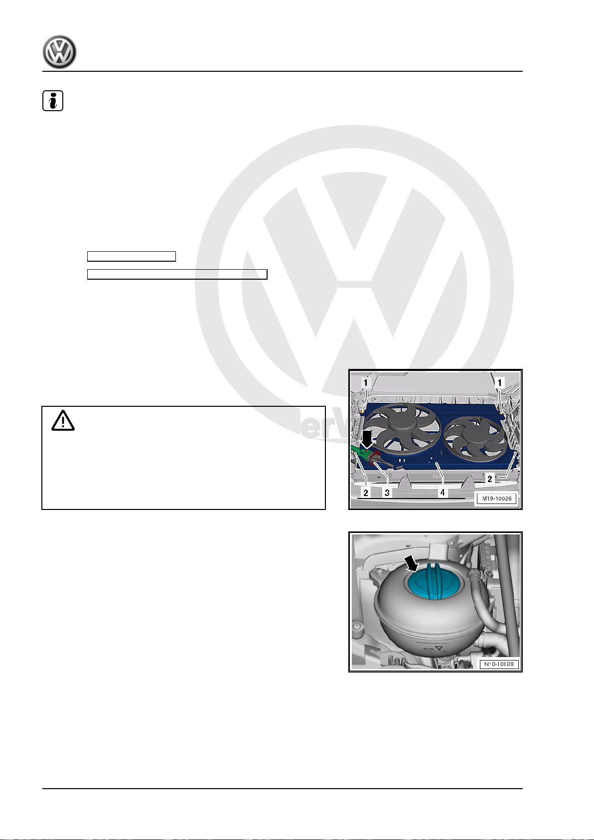
P
r
o
t
e
c
t
e
d
b
y
c
o
p
y
r
i
g
h
t
.
C
o
p
y
i
n
g
f
o
r
p
r
i
v
a
t
e
o
r
c
o
m
m
e
r
c
i
a
l
p
u
r
p
o
s
e
s
,
i
n
p
a
r
t
o
r
i
n
w
h
o
l
e
,
i
s
n
o
t
p
e
r
m
i
t
t
e
d
u
n
l
e
s
s
a
u
t
h
o
r
i
s
e
d
b
y
V
o
l
k
s
w
a
g
e
n
A
G
.
V
o
l
k
s
w
a
g
e
n
A
G
d
o
e
s
n
o
t
g
u
a
r
a
n
t
e
e
o
r
a
c
c
e
p
t
a
n
y
l
i
a
b
i
l
i
t
y
w
i
t
h
r
e
s
p
e
c
t
t
o
t
h
e
c
o
r
r
e
c
t
n
e
s
s
o
f
i
n
f
o
r
m
a
t
i
o
n
i
n
t
h
i
s
d
o
c
u
m
e
n
t
.
C
o
p
y
r
i
g
h
t
b
y
V
o
l
k
s
w
a
g
e
n
A
G
.
Jetta Hybrid 2013 ➤
Direct Shift Gearbox - Edition 01.2016
Note
♦
Secure the rear lid so that it cannot close because the battery
is going to be disconnected.
♦
Access to the luggage compartment when the power is off
possible but with difficulty.
• To de-energizing the high voltage system. Refer to ⇒ Hybrid
Electrical System; Rep. Gr. 93 ; Electric Drive; Turning off
Voltage .
– Move the selector lever into »P«.
– Connect the Vehicle Diagnostic Tester and turn on the ignition.
– Select Guided Functions .
– Select Move Gear Selector Into -Neutral- under “7-
speed DSG® transmission”.
– Turn off the ignition.
– Lift the vehicle.
– Remove the noise insulation below engine/transmission. Re‐
fer to ⇒ Body Exterior; Rep. Gr. 66 ; Overview - Noise
Insolation .
– Remove the fan shroud. Refer to ⇒ Engine Mechanical, Fuel
Injection and Ignition; Rep. Gr. 19 ; Radiator and Coolant Fan;
Fan Shroud, Removing and Installing .
WARNING
Risk of burning due to hot steam and hot coolant.
♦ When engine is warm, the cooling system is under pres‐
sure.
♦ Reduce pressure by cover coolant expansion tank cap
with cloths and carefully opening.
– Remove the cap -arrow- from the coolant reservoir.
– Place the Shop Crane - Drip Tray - VAS6208- underneath.
52 Rep. Gr.34 - Controls, Housing
Page 57
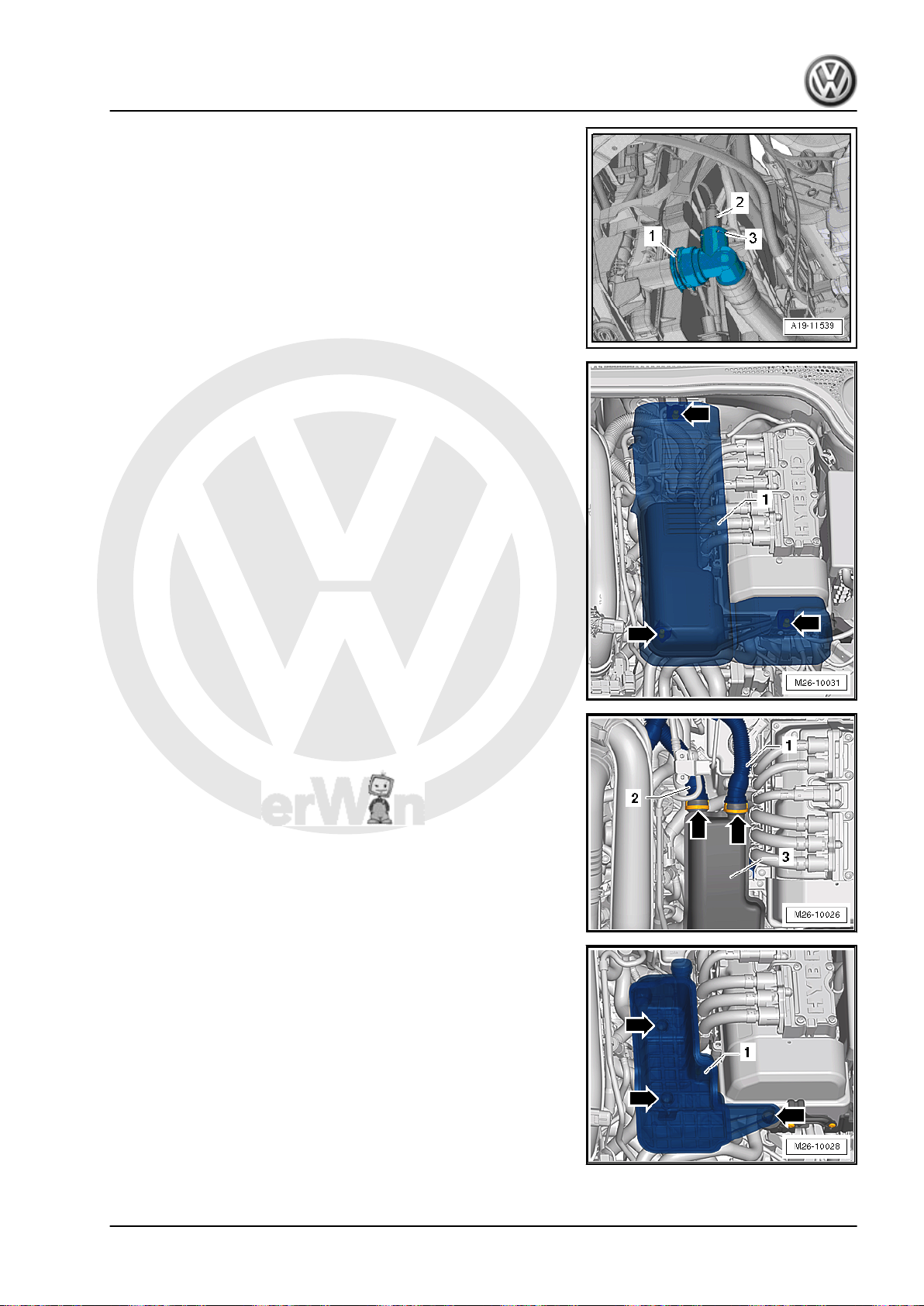
P
r
o
t
e
c
t
e
d
b
y
c
o
p
y
r
i
g
h
t
.
C
o
p
y
i
n
g
f
o
r
p
r
i
v
a
t
e
o
r
c
o
m
m
e
r
c
i
a
l
p
u
r
p
o
s
e
s
,
i
n
p
a
r
t
o
r
i
n
w
h
o
l
e
,
i
s
n
o
t
p
e
r
m
i
t
t
e
d
u
n
l
e
s
s
a
u
t
h
o
r
i
s
e
d
b
y
V
o
l
k
s
w
a
g
e
n
A
G
.
V
o
l
k
s
w
a
g
e
n
A
G
d
o
e
s
n
o
t
g
u
a
r
a
n
t
e
e
o
r
a
c
c
e
p
t
a
n
y
l
i
a
b
i
l
i
t
y
w
i
t
h
r
e
s
p
e
c
t
t
o
t
h
e
c
o
r
r
e
c
t
n
e
s
s
o
f
i
n
f
o
r
m
a
t
i
o
n
i
n
t
h
i
s
d
o
c
u
m
e
n
t
.
C
o
p
y
r
i
g
h
t
b
y
V
o
l
k
s
w
a
g
e
n
A
G
.
– Disconnect the connector -2- on the Engine Coolant Temper‐
ature Sensor on Radiator Outlet - G83- .
– Open the clamp -1-. Remove the left coolant hose at the bot‐
tom of the radiator and drain the coolant.
– Bring the lock carrier into the service position. Refer to ⇒ Body
Exterior; Rep. Gr. 50 ; Lock Carrier; Service Position, Per‐
forming and Resetting .
– Unclip and remove the damper cover -1- upward from the re‐
tainers -arrows-.
Vehicles with Secondary Air Injection (AIR) System
– Squeeze the locking ring -arrows- on both sides and remove
the air lines -1 and 2- from the damper -3-.
Jetta Hybrid 2013 ➤
Direct Shift Gearbox - Edition 01.2016
– Remove the damper -1- upward from the rubber bushings
-arrows-.
For All Vehicles
– Disconnect the 12V battery. Refer to ⇒ Electrical Equipment;
Rep. Gr. 27 ; Battery, Disconnecting and Connecting .
1. Mechatronic 53
Page 58
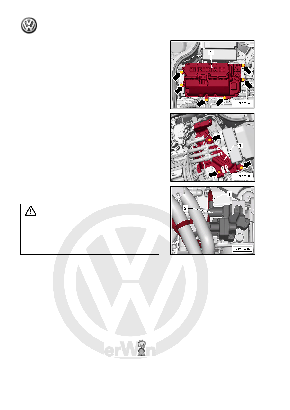
P
r
o
t
e
c
t
e
d
b
y
c
o
p
y
r
i
g
h
t
.
C
o
p
y
i
n
g
f
o
r
p
r
i
v
a
t
e
o
r
c
o
m
m
e
r
c
i
a
l
p
u
r
p
o
s
e
s
,
i
n
p
a
r
t
o
r
i
n
w
h
o
l
e
,
i
s
n
o
t
p
e
r
m
i
t
t
e
d
u
n
l
e
s
s
a
u
t
h
o
r
i
s
e
d
b
y
V
o
l
k
s
w
a
g
e
n
A
G
.
V
o
l
k
s
w
a
g
e
n
A
G
d
o
e
s
n
o
t
g
u
a
r
a
n
t
e
e
o
r
a
c
c
e
p
t
a
n
y
l
i
a
b
i
l
i
t
y
w
i
t
h
r
e
s
p
e
c
t
t
o
t
h
e
c
o
r
r
e
c
t
n
e
s
s
o
f
i
n
f
o
r
m
a
t
i
o
n
i
n
t
h
i
s
d
o
c
u
m
e
n
t
.
C
o
p
y
r
i
g
h
t
b
y
V
o
l
k
s
w
a
g
e
n
A
G
.
Jetta Hybrid 2013 ➤
Direct Shift Gearbox - Edition 01.2016
– Remove the Electric Drive Power and Control Electronics -
JX1- . Refer to ⇒ Electrical Equipment; Rep. Gr. 93 ; Electric
Drive Power and Control Electronics; Electric Drive Power and
Control Electronics, Removing and Installing .
– Remove the high voltage cables bracket from the transmission
housing. Shown in illustration below, not called out.
– Remove the bracket -1- for the Electric Drive Power And Con‐
trol Electronics - JX1- -arrows-. Refer to ⇒ Electrical System
Hybrid; Rep. Gr. 93 ; High Voltage Cables; High Voltage Bat‐
tery High Voltage Cable Set, Removing and Installing .
– Disconnect the connector -1- from the valve -2- on the Me‐
chatronic and pull the wiring harness from the front bracket on
the transmission.
WARNING
Danger of dirt.
Always clean the connection locations and the area around
them before loosening.
The Mechatronic hydraulic system is not open. Dirt can cause
the system to malfunction.
If Hydraulic Line Doesn’t Need to Be Removed
– Remove the clamps -2- from the valve block/Mechatronic.
– Seal the hydraulic line connection -2- with new sealing plug
-3-.
If Hydraulic Line Needs to be removed
– Remove the bolt -1- for the hydraulic line -3- on the engine.
– Remove the clamps -2- from the valve block/Mechatronic.
54 Rep. Gr.34 - Controls, Housing
Page 59
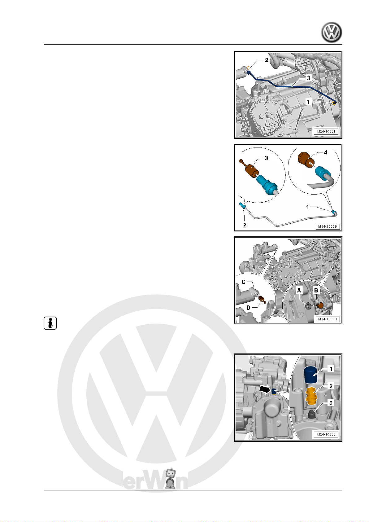
P
r
o
t
e
c
t
e
d
b
y
c
o
p
y
r
i
g
h
t
.
C
o
p
y
i
n
g
f
o
r
p
r
i
v
a
t
e
o
r
c
o
m
m
e
r
c
i
a
l
p
u
r
p
o
s
e
s
,
i
n
p
a
r
t
o
r
i
n
w
h
o
l
e
,
i
s
n
o
t
p
e
r
m
i
t
t
e
d
u
n
l
e
s
s
a
u
t
h
o
r
i
s
e
d
b
y
V
o
l
k
s
w
a
g
e
n
A
G
.
V
o
l
k
s
w
a
g
e
n
A
G
d
o
e
s
n
o
t
g
u
a
r
a
n
t
e
e
o
r
a
c
c
e
p
t
a
n
y
l
i
a
b
i
l
i
t
y
w
i
t
h
r
e
s
p
e
c
t
t
o
t
h
e
c
o
r
r
e
c
t
n
e
s
s
o
f
i
n
f
o
r
m
a
t
i
o
n
i
n
t
h
i
s
d
o
c
u
m
e
n
t
.
C
o
p
y
r
i
g
h
t
b
y
V
o
l
k
s
w
a
g
e
n
A
G
.
Direct Shift Gearbox - Edition 01.2016
– Remove the hydraulic line -3- on the engine and valve block/
Mechatronic at the same time.
Jetta Hybrid 2013 ➤
• Seal the hydraulic line connections -1 and 2- immediately with
new sealing plugs -3 and 4- from the Repair Kit - 5C0 998
152- . Preferably the hydraulic fluid should remain in the line
if possible, otherwise it should not become dirty.
• Seal the connections on the engine -A- and the valve block/
Mechatronic -C- with new sealing plugs -B and D- from the
Repair Kit - 5C0 998 152- .
• Always use new plugs from the Repair Kit - 5C0 998 152- .
Refer to the Parts Catalog. The sealing plugs cannot be used
again.
Note
The engine/transmission is not shown in the illustration.
– Remove the cap -1- from the Mechatronic. The bleeder -2-
remains on the ventilation -3- while doing this.
1. Mechatronic 55
Page 60
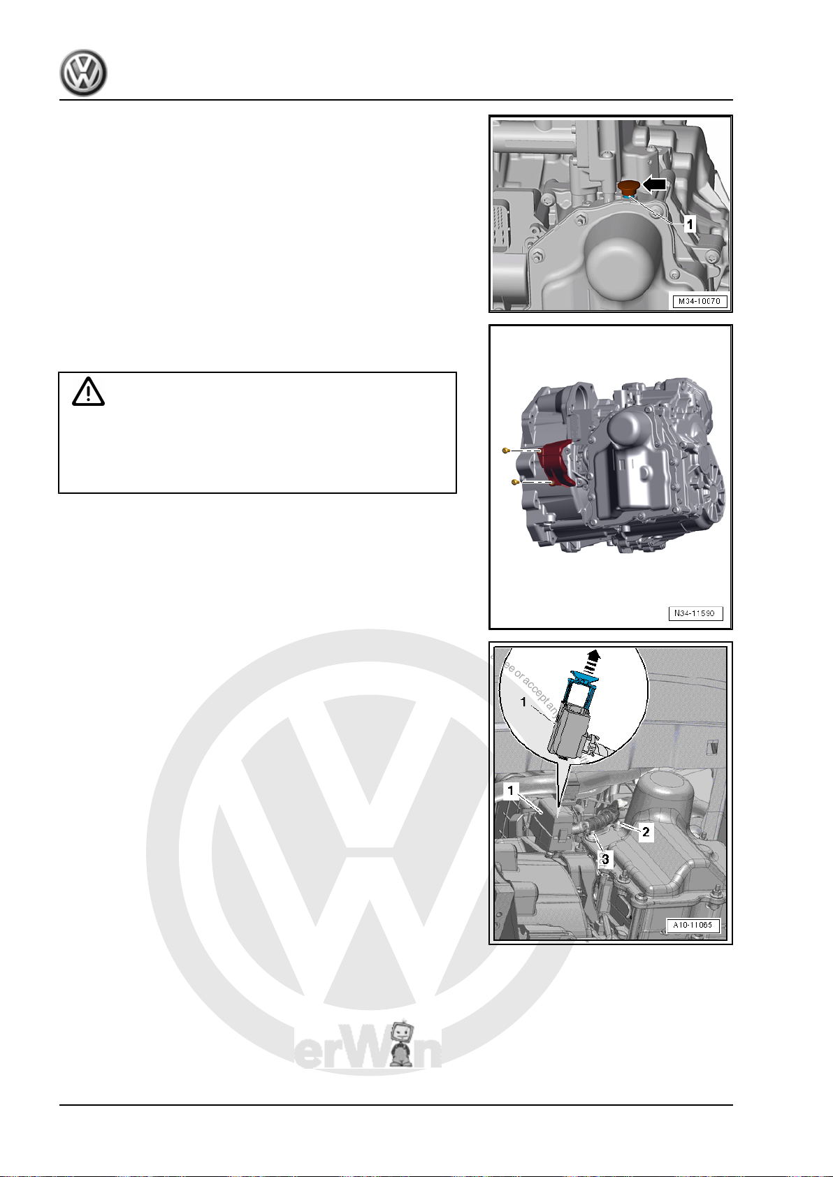
P
r
o
t
e
c
t
e
d
b
y
c
o
p
y
r
i
g
h
t
.
C
o
p
y
i
n
g
f
o
r
p
r
i
v
a
t
e
o
r
c
o
m
m
e
r
c
i
a
l
p
u
r
p
o
s
e
s
,
i
n
p
a
r
t
o
r
i
n
w
h
o
l
e
,
i
s
n
o
t
p
e
r
m
i
t
t
e
d
u
n
l
e
s
s
a
u
t
h
o
r
i
s
e
d
b
y
V
o
l
k
s
w
a
g
e
n
A
G
.
V
o
l
k
s
w
a
g
e
n
A
G
d
o
e
s
n
o
t
g
u
a
r
a
n
t
e
e
o
r
a
c
c
e
p
t
a
n
y
l
i
a
b
i
l
i
t
y
w
i
t
h
r
e
s
p
e
c
t
t
o
t
h
e
c
o
r
r
e
c
t
n
e
s
s
o
f
i
n
f
o
r
m
a
t
i
o
n
i
n
t
h
i
s
d
o
c
u
m
e
n
t
.
C
o
p
y
r
i
g
h
t
b
y
V
o
l
k
s
w
a
g
e
n
A
G
.
Jetta Hybrid 2013 ➤
Direct Shift Gearbox - Edition 01.2016
• The bleeder -2- must be removed so that no hydraulic fluid can
leak out of the Mechatronic.
• The bleeder will get damaged and must be replaced during
installation.
• Seal the breather -1- with a plug or the Protective Cap - 0AM
325 120 A- so that no fluid can leak out -arrow-. Refer to the
Parts Catalog.
– If equipped remove the cover over the engaging levers.
The cover prevents dirt from getting in.
Caution
Risk of damaging transmission components.
♦ Never touch the contacts in the transmission connector.
The electrostatic discharge will damage the control mod‐
ule and Mechatronic.
– To electrostatically discharge, touch the Ground (GND) (with‐
out glove).
– Disconnect the connector -1- for the DSG Transmission Me‐
chatronic - J743- by pulling the locking mechanism upward in
direction of -arrow-.
– Remove the nuts -2 and 3- from the double bolts.
– Remove the bracket for the electric wires from the transmis‐
sion.
56 Rep. Gr.34 - Controls, Housing
Page 61
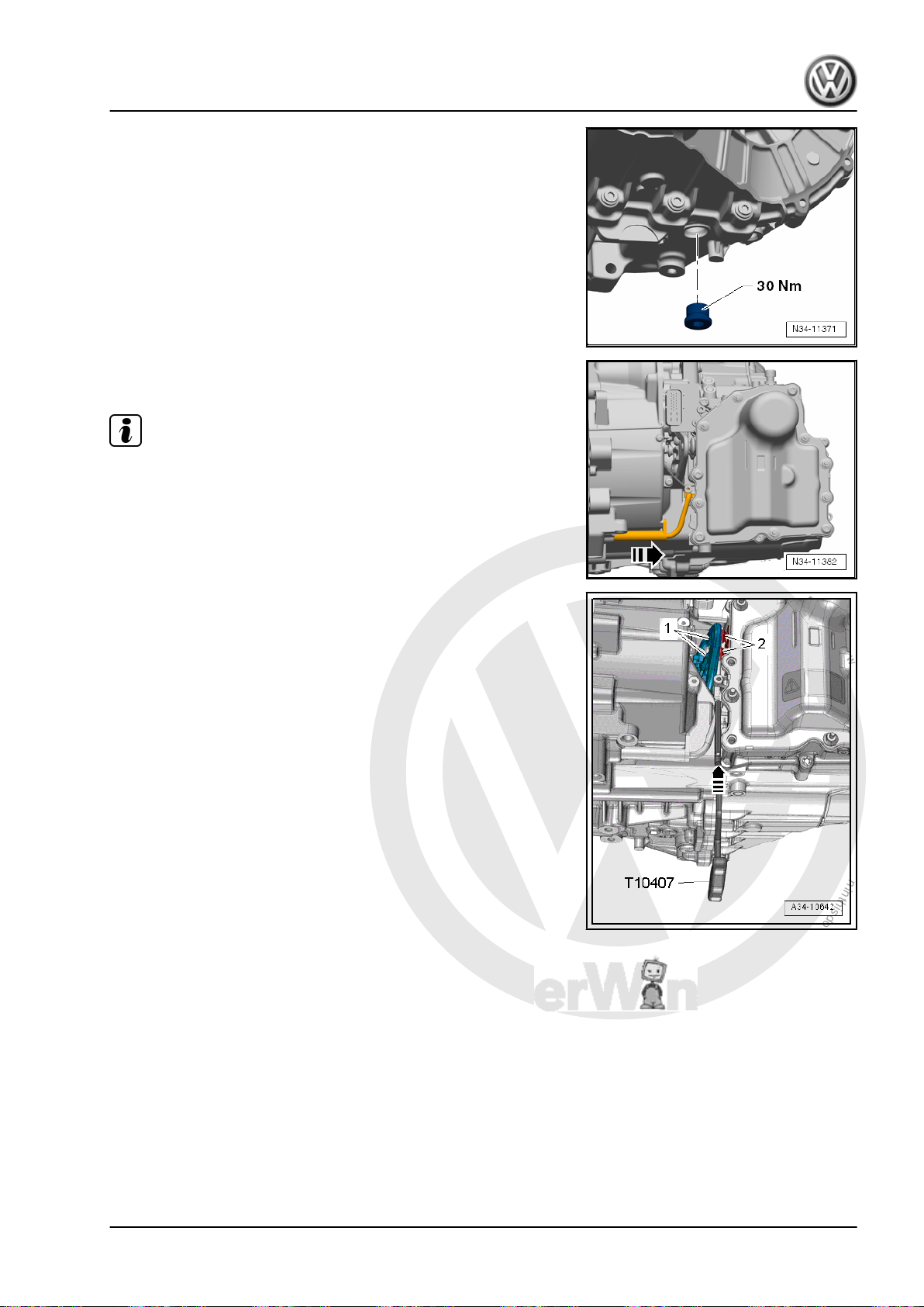
P
r
o
t
e
c
t
e
d
b
y
c
o
p
y
r
i
g
h
t
.
C
o
p
y
i
n
g
f
o
r
p
r
i
v
a
t
e
o
r
c
o
m
m
e
r
c
i
a
l
p
u
r
p
o
s
e
s
,
i
n
p
a
r
t
o
r
i
n
w
h
o
l
e
,
i
s
n
o
t
p
e
r
m
i
t
t
e
d
u
n
l
e
s
s
a
u
t
h
o
r
i
s
e
d
b
y
V
o
l
k
s
w
a
g
e
n
A
G
.
V
o
l
k
s
w
a
g
e
n
A
G
d
o
e
s
n
o
t
g
u
a
r
a
n
t
e
e
o
r
a
c
c
e
p
t
a
n
y
l
i
a
b
i
l
i
t
y
w
i
t
h
r
e
s
p
e
c
t
t
o
t
h
e
c
o
r
r
e
c
t
n
e
s
s
o
f
i
n
f
o
r
m
a
t
i
o
n
i
n
t
h
i
s
d
o
c
u
m
e
n
t
.
C
o
p
y
r
i
g
h
t
b
y
V
o
l
k
s
w
a
g
e
n
A
G
.
Direct Shift Gearbox - Edition 01.2016
– Place the Used Oil Collection and Extraction Unit -
SMN372500- underneath.
– Remove the drain plug from the transmission.
– Drain the fluid and then install the drain plug and tighten it.
– Unclip Transmission Input Speed Sensor 3 - G641- carefully
from the housing in direction of -arrow- with a screwdriver.
Note
In the following work step, both engaging levers on the dual clutch
are lifted by the Mechatronic valve lifters. Otherwise the engaging
levers will jam the Mechatronic by the lifters and then it is not
possible to remove the Mechatronic.
– Insert the Assembly Lever - Mechatronic - T10407- under the
lifter -2- between the transmission housing and both engaging
levers -1- in direction of -arrow-, as illustrated.
Jetta Hybrid 2013 ➤
1. Mechatronic 57
Page 62
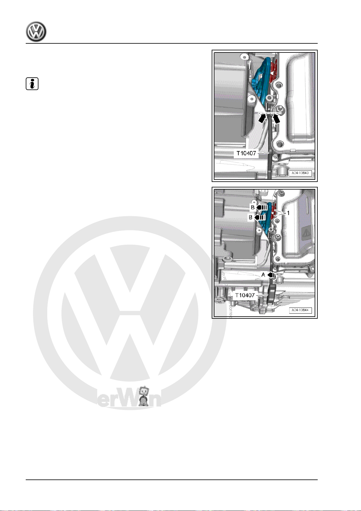
P
r
o
t
e
c
t
e
d
b
y
c
o
p
y
r
i
g
h
t
.
C
o
p
y
i
n
g
f
o
r
p
r
i
v
a
t
e
o
r
c
o
m
m
e
r
c
i
a
l
p
u
r
p
o
s
e
s
,
i
n
p
a
r
t
o
r
i
n
w
h
o
l
e
,
i
s
n
o
t
p
e
r
m
i
t
t
e
d
u
n
l
e
s
s
a
u
t
h
o
r
i
s
e
d
b
y
V
o
l
k
s
w
a
g
e
n
A
G
.
V
o
l
k
s
w
a
g
e
n
A
G
d
o
e
s
n
o
t
g
u
a
r
a
n
t
e
e
o
r
a
c
c
e
p
t
a
n
y
l
i
a
b
i
l
i
t
y
w
i
t
h
r
e
s
p
e
c
t
t
o
t
h
e
c
o
r
r
e
c
t
n
e
s
s
o
f
i
n
f
o
r
m
a
t
i
o
n
i
n
t
h
i
s
d
o
c
u
m
e
n
t
.
C
o
p
y
r
i
g
h
t
b
y
V
o
l
k
s
w
a
g
e
n
A
G
.
Jetta Hybrid 2013 ➤
Direct Shift Gearbox - Edition 01.2016
– Insert the Assembly Lever - Mechatronic - T10407- just far
enough until the groove on it lines up with the rib on the hous‐
ing -arrows-, as illustrated. Do not insert it all the way.
Note
The back of the Assembly Lever must touch the transmission
housing.
– Turn the Assembly Lever - Mechatronic - T10407- counter-
clockwise 90° -arrow A-, in order to lift the engaging lever off
the lifters -1- in direction of -arrow B-.
58 Rep. Gr.34 - Controls, Housing
Page 63
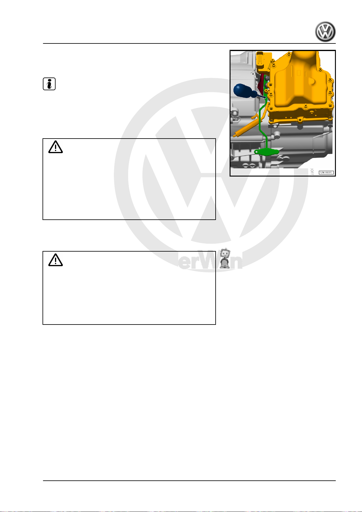
P
r
o
t
e
c
t
e
d
b
y
c
o
p
y
r
i
g
h
t
.
C
o
p
y
i
n
g
f
o
r
p
r
i
v
a
t
e
o
r
c
o
m
m
e
r
c
i
a
l
p
u
r
p
o
s
e
s
,
i
n
p
a
r
t
o
r
i
n
w
h
o
l
e
,
i
s
n
o
t
p
e
r
m
i
t
t
e
d
u
n
l
e
s
s
a
u
t
h
o
r
i
s
e
d
b
y
V
o
l
k
s
w
a
g
e
n
A
G
.
V
o
l
k
s
w
a
g
e
n
A
G
d
o
e
s
n
o
t
g
u
a
r
a
n
t
e
e
o
r
a
c
c
e
p
t
a
n
y
l
i
a
b
i
l
i
t
y
w
i
t
h
r
e
s
p
e
c
t
t
o
t
h
e
c
o
r
r
e
c
t
n
e
s
s
o
f
i
n
f
o
r
m
a
t
i
o
n
i
n
t
h
i
s
d
o
c
u
m
e
n
t
.
C
o
p
y
r
i
g
h
t
b
y
V
o
l
k
s
w
a
g
e
n
A
G
.
Direct Shift Gearbox - Edition 01.2016
– Hold the Assembly Lever - Mechatronic - T10407- against the
transmission housing with a screwdriver to prevent it from slip‐
ping while turning it.
Note
♦
The Assembly Lever - Mechatronic - T10407- remains inser‐
ted between the engaging levers and transmission housing
while removing and installing the Mechatronic.
♦
Press the Assembly Lever - Mechatronic - T10407- against the
transmission housing, if necessary.
Caution
Risk of damaging transmission components.
♦ Touch or remove the DSG Transmission Mechatronic -
J743- only after having electrostatically discharged your‐
self by touching a grounded metal object (for example,
bare handed with a ground).
♦ Never touch the contacts in the transmission connector.
The control module as well as the Mechatronic can be‐
come damaged by the static discharge.
– To electrostatically discharge, touch the ground (without
glove). Do not touch connector or »open« electronic compo‐
nents directly.
Caution
Risk of damaging the DSG Transmission Mechatronic - J743- .
Jetta Hybrid 2013 ➤
♦ Do not loosen the bolts on the cover for the DSG Trans‐
mission Mechatronic - J743- .
♦ Place the removed DSG Transmission Mechatronic -
J743- so that no fluid can leak out.
♦ Do not remove the valve block from the Mechatronic .
1. Mechatronic 59
Page 64
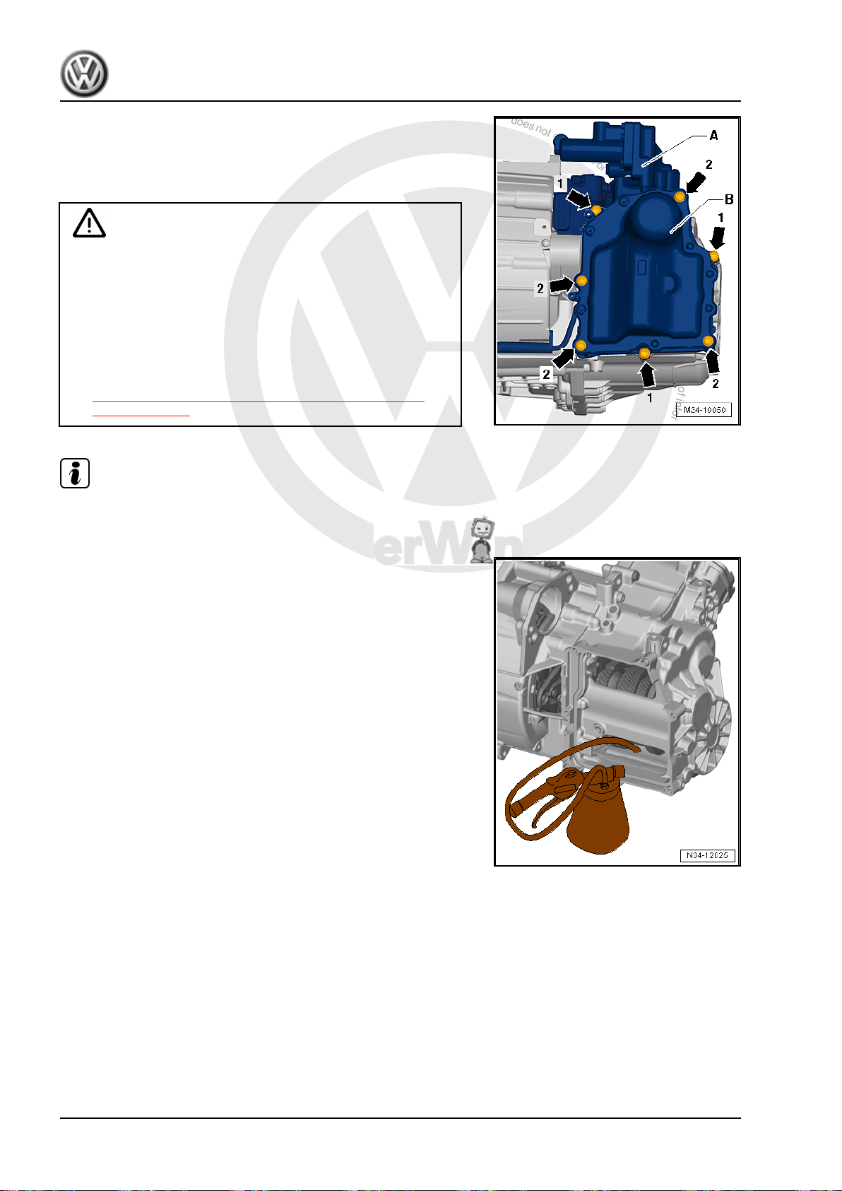
P
r
o
t
e
c
t
e
d
b
y
c
o
p
y
r
i
g
h
t
.
C
o
p
y
i
n
g
f
o
r
p
r
i
v
a
t
e
o
r
c
o
m
m
e
r
c
i
a
l
p
u
r
p
o
s
e
s
,
i
n
p
a
r
t
o
r
i
n
w
h
o
l
e
,
i
s
n
o
t
p
e
r
m
i
t
t
e
d
u
n
l
e
s
s
a
u
t
h
o
r
i
s
e
d
b
y
V
o
l
k
s
w
a
g
e
n
A
G
.
V
o
l
k
s
w
a
g
e
n
A
G
d
o
e
s
n
o
t
g
u
a
r
a
n
t
e
e
o
r
a
c
c
e
p
t
a
n
y
l
i
a
b
i
l
i
t
y
w
i
t
h
r
e
s
p
e
c
t
t
o
t
h
e
c
o
r
r
e
c
t
n
e
s
s
o
f
i
n
f
o
r
m
a
t
i
o
n
i
n
t
h
i
s
d
o
c
u
m
e
n
t
.
C
o
p
y
r
i
g
h
t
b
y
V
o
l
k
s
w
a
g
e
n
A
G
.
Jetta Hybrid 2013 ➤
Direct Shift Gearbox - Edition 01.2016
– Remove the bolts -arrows 2- diagonally.
– Remove the bolts -arrows 1-.
– Remove the Mechatronic -B- and valve block -A- from the
transmission.
Caution
Risk of damaging the DSG Transmission Mechatronic - J743- .
♦ It may not be possible to remove the Mechatronic.
♦ In this case, the gear selector is caught on the top of the
Mechatronic on the left side.
♦ Do not use increased force to remove the Mechatronic.
♦ In this case, it will be necessary to manually move the
Mechatronic into its removal position. Refer to
⇒ “1.3 Mechatronic, Moving into Removal Position by
Hand”, page 69 .
Note
Before installing the Mechatronic the rest of the oil must be ex‐
tracted from the transmission.
– Extract the remaining oil from the transmission using the Suc‐
tion Pump - VAS5226- .
Installing
60 Rep. Gr.34 - Controls, Housing
Page 65
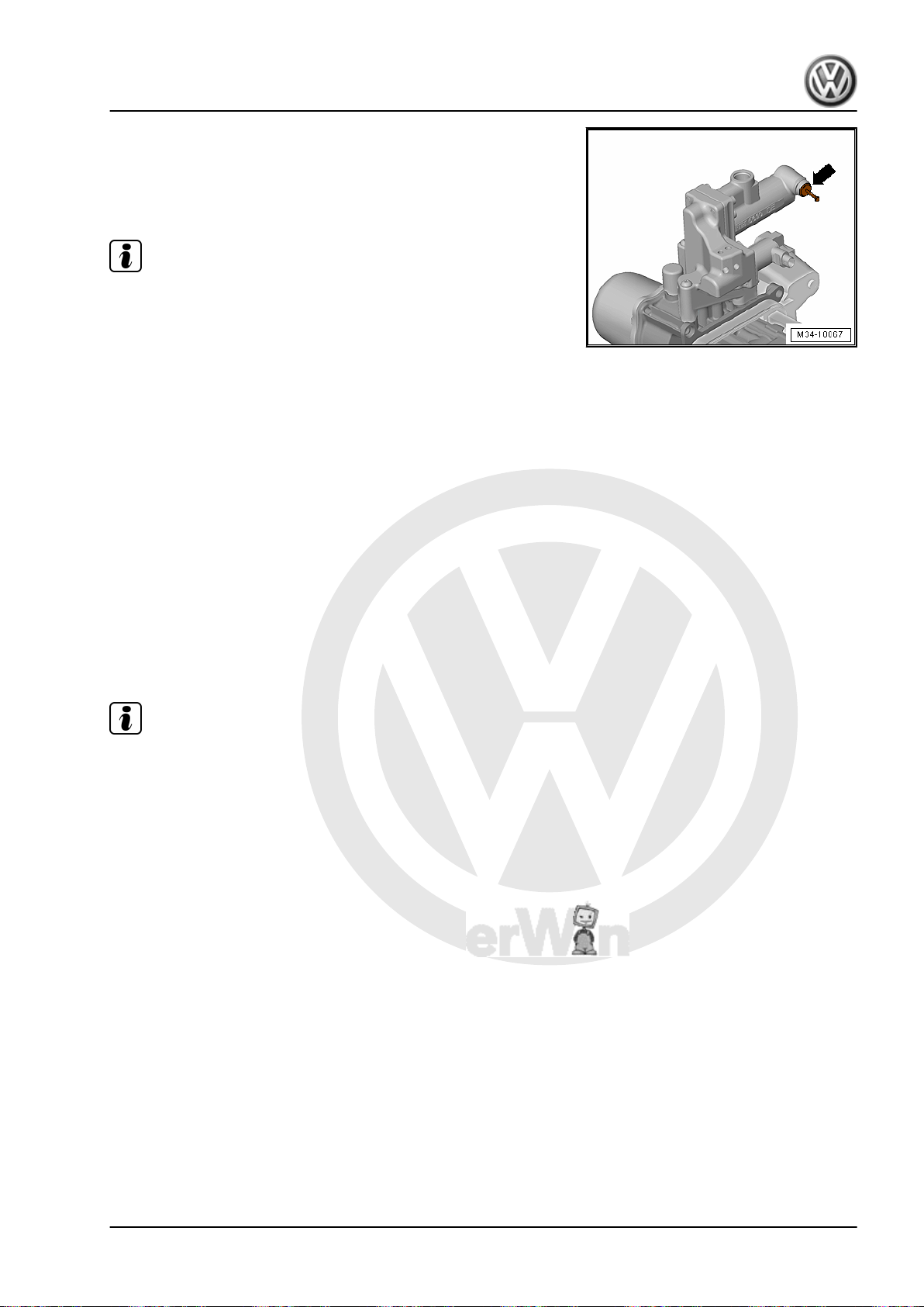
P
r
o
t
e
c
t
e
d
b
y
c
o
p
y
r
i
g
h
t
.
C
o
p
y
i
n
g
f
o
r
p
r
i
v
a
t
e
o
r
c
o
m
m
e
r
c
i
a
l
p
u
r
p
o
s
e
s
,
i
n
p
a
r
t
o
r
i
n
w
h
o
l
e
,
i
s
n
o
t
p
e
r
m
i
t
t
e
d
u
n
l
e
s
s
a
u
t
h
o
r
i
s
e
d
b
y
V
o
l
k
s
w
a
g
e
n
A
G
.
V
o
l
k
s
w
a
g
e
n
A
G
d
o
e
s
n
o
t
g
u
a
r
a
n
t
e
e
o
r
a
c
c
e
p
t
a
n
y
l
i
a
b
i
l
i
t
y
w
i
t
h
r
e
s
p
e
c
t
t
o
t
h
e
c
o
r
r
e
c
t
n
e
s
s
o
f
i
n
f
o
r
m
a
t
i
o
n
i
n
t
h
i
s
d
o
c
u
m
e
n
t
.
C
o
p
y
r
i
g
h
t
b
y
V
o
l
k
s
w
a
g
e
n
A
G
.
Direct Shift Gearbox - Edition 01.2016
• Seal the Mechatronic vent with a plug or the Protective Cap 0AM 325 120 A- so that no fluid can leak out. Refer to the Parts
Catalog.
• The connection on the valve block/Mechatronic is sealed with
a sealing plug -arrow- from the Repair Kit - 5C0 998 152- .
Note
♦
The fluid in a new Mechatronic is already filled correctly.
♦
The new Mechatronic is already sealed with the Protective
Cap - 0AM 325 120 A- .
♦
Make sure all shift forks are in the center position before in‐
stalling the DSG Transmission Mechatronic - J743- .
♦
The following illustration shows the center position as -N-.
♦
In this position, there is no gear engaged and neutral is se‐
lected.
– Check each of the 4 shift forks by hand first.
Each shift fork has three positions:
♦ Gear engaged
♦ Neutral -N-
♦ Gear engaged
– Move all four shift forks one time into each position -arrows-
one after the other.
– After doing this, move the shift forks back into the center po‐
sition -N-.
Note
Turning the switch slightly makes it easier to shift the forks.
Jetta Hybrid 2013 ➤
1. Mechatronic 61
Page 66
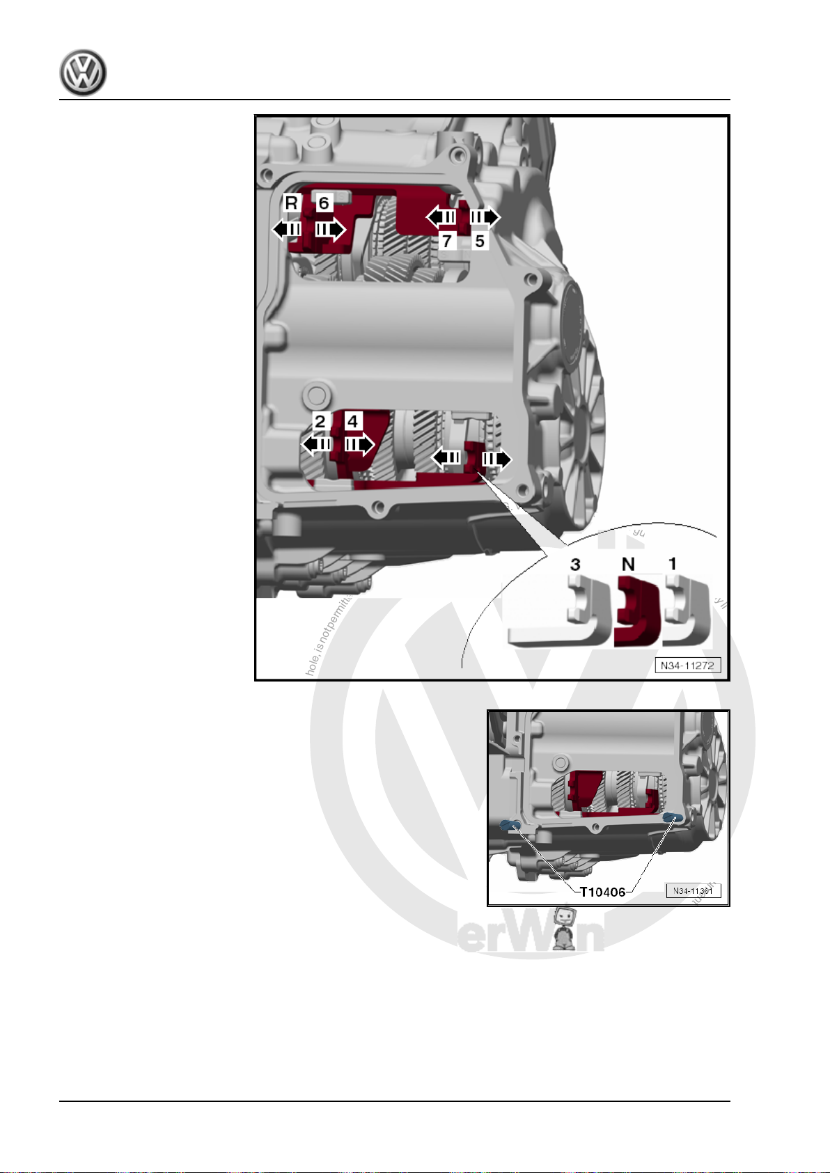
P
r
o
t
e
c
t
e
d
b
y
c
o
p
y
r
i
g
h
t
.
C
o
p
y
i
n
g
f
o
r
p
r
i
v
a
t
e
o
r
c
o
m
m
e
r
c
i
a
l
p
u
r
p
o
s
e
s
,
i
n
p
a
r
t
o
r
i
n
w
h
o
l
e
,
i
s
n
o
t
p
e
r
m
i
t
t
e
d
u
n
l
e
s
s
a
u
t
h
o
r
i
s
e
d
b
y
V
o
l
k
s
w
a
g
e
n
A
G
.
V
o
l
k
s
w
a
g
e
n
A
G
d
o
e
s
n
o
t
g
u
a
r
a
n
t
e
e
o
r
a
c
c
e
p
t
a
n
y
l
i
a
b
i
l
i
t
y
w
i
t
h
r
e
s
p
e
c
t
t
o
t
h
e
c
o
r
r
e
c
t
n
e
s
s
o
f
i
n
f
o
r
m
a
t
i
o
n
i
n
t
h
i
s
d
o
c
u
m
e
n
t
.
C
o
p
y
r
i
g
h
t
b
y
V
o
l
k
s
w
a
g
e
n
A
G
.
Jetta Hybrid 2013 ➤
Direct Shift Gearbox - Edition 01.2016
N - Neutral
R - Reverse Gear
1 - First Gear
2 - Second Gear
3 - Third Gear
4 - Fourth Gear
5 - Fifth Gear
6 - Sixth Gear
7 - Seventh Gear
– Clean the sealing surface, which the Mechatronic will be
touching later.
– Install the Guide Bolt - Mechatronic - T10406- hand tight.
62 Rep. Gr.34 - Controls, Housing
Page 67
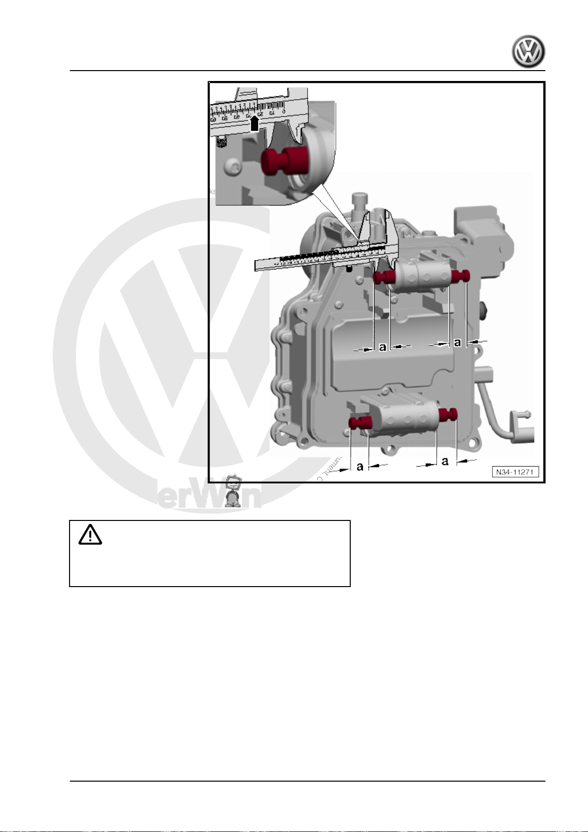
P
r
o
t
e
c
t
e
d
b
y
c
o
p
y
r
i
g
h
t
.
C
o
p
y
i
n
g
f
o
r
p
r
i
v
a
t
e
o
r
c
o
m
m
e
r
c
i
a
l
p
u
r
p
o
s
e
s
,
i
n
p
a
r
t
o
r
i
n
w
h
o
l
e
,
i
s
n
o
t
p
e
r
m
i
t
t
e
d
u
n
l
e
s
s
a
u
t
h
o
r
i
s
e
d
b
y
V
o
l
k
s
w
a
g
e
n
A
G
.
V
o
l
k
s
w
a
g
e
n
A
G
d
o
e
s
n
o
t
g
u
a
r
a
n
t
e
e
o
r
a
c
c
e
p
t
a
n
y
l
i
a
b
i
l
i
t
y
w
i
t
h
r
e
s
p
e
c
t
t
o
t
h
e
c
o
r
r
e
c
t
n
e
s
s
o
f
i
n
f
o
r
m
a
t
i
o
n
i
n
t
h
i
s
d
o
c
u
m
e
n
t
.
C
o
p
y
r
i
g
h
t
b
y
V
o
l
k
s
w
a
g
e
n
A
G
.
Adjust the gear selector:
Jetta Hybrid 2013 ➤
Direct Shift Gearbox - Edition 01.2016
Caution
Risk of damaging the DSG Transmission Mechatronic - J743- .
Do not pry out the plunger on the sensors.
– Move the four gear selectors on the back of the DSG Trans‐
mission Mechatronic - J743- into the correct positions.
– Clean the sealing surface on the Mechatronic.
1. Mechatronic 63
Page 68
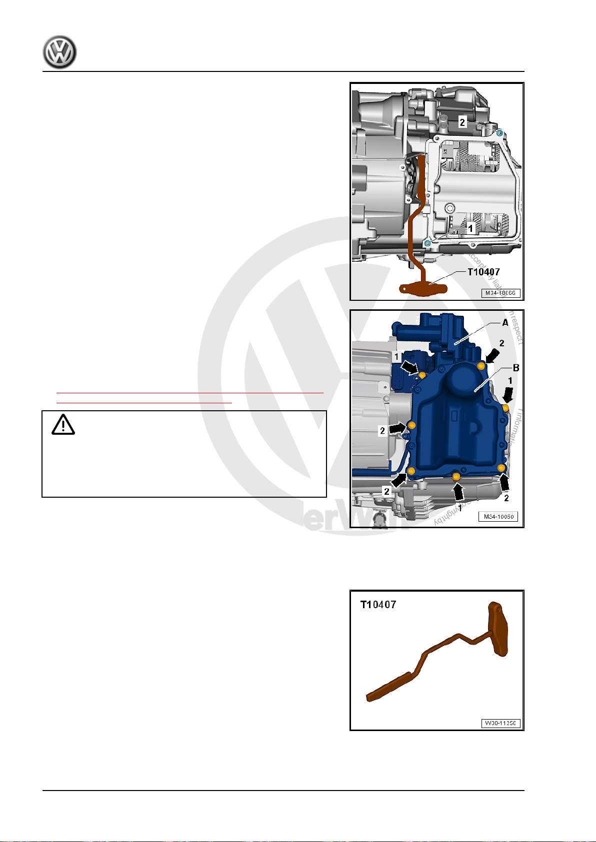
P
r
o
t
e
c
t
e
d
b
y
c
o
p
y
r
i
g
h
t
.
C
o
p
y
i
n
g
f
o
r
p
r
i
v
a
t
e
o
r
c
o
m
m
e
r
c
i
a
l
p
u
r
p
o
s
e
s
,
i
n
p
a
r
t
o
r
i
n
w
h
o
l
e
,
i
s
n
o
t
p
e
r
m
i
t
t
e
d
u
n
l
e
s
s
a
u
t
h
o
r
i
s
e
d
b
y
V
o
l
k
s
w
a
g
e
n
A
G
.
V
o
l
k
s
w
a
g
e
n
A
G
d
o
e
s
n
o
t
g
u
a
r
a
n
t
e
e
o
r
a
c
c
e
p
t
a
n
y
l
i
a
b
i
l
i
t
y
w
i
t
h
r
e
s
p
e
c
t
t
o
t
h
e
c
o
r
r
e
c
t
n
e
s
s
o
f
i
n
f
o
r
m
a
t
i
o
n
i
n
t
h
i
s
d
o
c
u
m
e
n
t
.
C
o
p
y
r
i
g
h
t
b
y
V
o
l
k
s
w
a
g
e
n
A
G
.
Jetta Hybrid 2013 ➤
Direct Shift Gearbox - Edition 01.2016
• The seal on the DSG Transmission Mechatronic - J743- must
fit completely into the groove.
• The Assembly Lever - T10407- is inserted between the en‐
gaging lever and the transmission housing.
• The two alignment sleeves -1 and 2- for centering the Mecha‐
tronic on the transmission housing must be installed.
– Mount the Mechatronic -B- together with the valve block -A-.
Make sure that the Mechatronic gear positions are not pressed
out of their position.
– Hand-tighten bolts -arrows 1 and 2- and remove the Guide Bolt
- Mechatronic - T10406- .
– Tighten the Mechatronic bolts. Refer to
⇒ Fig. ““ DSG Transmission Mechatronic -J743- - Tightening
Specification and Sequence”“ , page 50 .
Caution
There is a risk of damaging the clutches.
♦ If the engaging levers hit the Mechatronic clutch position‐
er, they will get overloaded and the clutch self-adjustment
will be active. It is not possible to reset the self-adjustment.
• Both clutch positioners must fit correctly into the mounts on
the clutch engaging levers.
• The rubber grommets on the clutch positioners must not be
damaged.
• The rubber grommets must seal the Mechatronic tight.
– Turn the Assembly Lever - Mechatronic - T10407- slowly and
carefully clockwise and remove it.
64 Rep. Gr.34 - Controls, Housing
Page 69
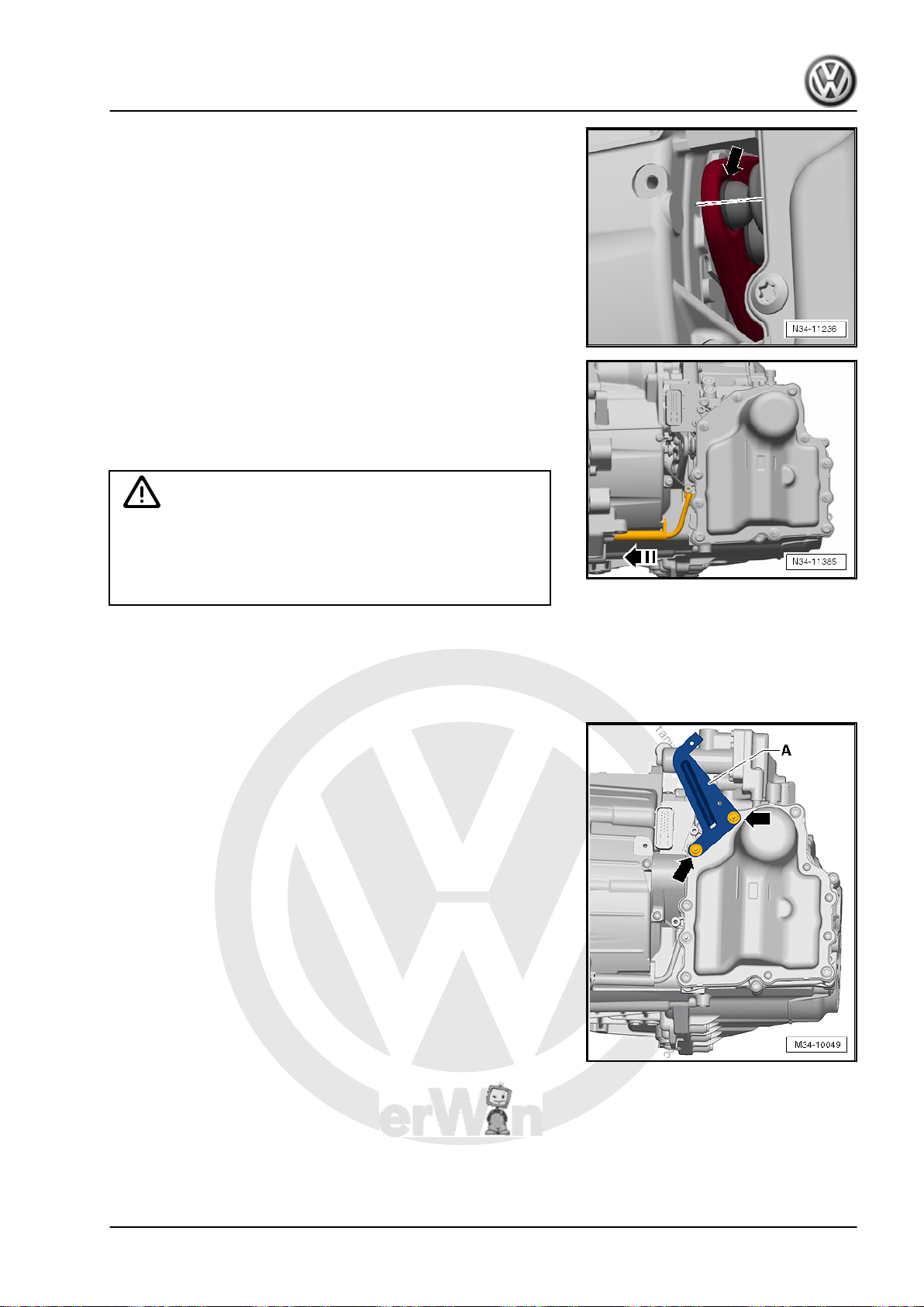
P
r
o
t
e
c
t
e
d
b
y
c
o
p
y
r
i
g
h
t
.
C
o
p
y
i
n
g
f
o
r
p
r
i
v
a
t
e
o
r
c
o
m
m
e
r
c
i
a
l
p
u
r
p
o
s
e
s
,
i
n
p
a
r
t
o
r
i
n
w
h
o
l
e
,
i
s
n
o
t
p
e
r
m
i
t
t
e
d
u
n
l
e
s
s
a
u
t
h
o
r
i
s
e
d
b
y
V
o
l
k
s
w
a
g
e
n
A
G
.
V
o
l
k
s
w
a
g
e
n
A
G
d
o
e
s
n
o
t
g
u
a
r
a
n
t
e
e
o
r
a
c
c
e
p
t
a
n
y
l
i
a
b
i
l
i
t
y
w
i
t
h
r
e
s
p
e
c
t
t
o
t
h
e
c
o
r
r
e
c
t
n
e
s
s
o
f
i
n
f
o
r
m
a
t
i
o
n
i
n
t
h
i
s
d
o
c
u
m
e
n
t
.
C
o
p
y
r
i
g
h
t
b
y
V
o
l
k
s
w
a
g
e
n
A
G
.
Direct Shift Gearbox - Edition 01.2016
• The lifters must move slowly into the mounts.
– Pull the lifters far enough until they fit correctly in the mounts.
– Install the Transmission Input Speed Sensor 3 - G641- .
– Be careful of the sensor. The clip must not be damaged.
• The sensor must fit completely in its retainer and must be
touching the transmission housing. Replace the Mechatronic
if the sensor is loose or if the clip is broken.
Caution
Danger of causing damage to transmission components.
Jetta Hybrid 2013 ➤
♦ Never touch the contacts in the transmission connector.
The control module as well as the Mechatronic can be‐
come damaged by the static discharge.
– To electrostatically discharge, touch the ground (without
glove). Do not touch connector or »open« electronic compo‐
nents directly.
– Connect and lock the Mechatronic connector.
– Attach the front bracket -A- to the transmission -arrows-.
1. Mechatronic 65
Page 70
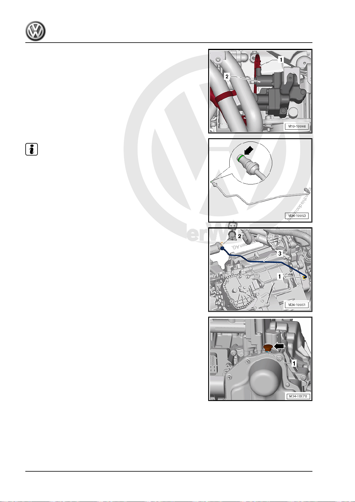
P
r
o
t
e
c
t
e
d
b
y
c
o
p
y
r
i
g
h
t
.
C
o
p
y
i
n
g
f
o
r
p
r
i
v
a
t
e
o
r
c
o
m
m
e
r
c
i
a
l
p
u
r
p
o
s
e
s
,
i
n
p
a
r
t
o
r
i
n
w
h
o
l
e
,
i
s
n
o
t
p
e
r
m
i
t
t
e
d
u
n
l
e
s
s
a
u
t
h
o
r
i
s
e
d
b
y
V
o
l
k
s
w
a
g
e
n
A
G
.
V
o
l
k
s
w
a
g
e
n
A
G
d
o
e
s
n
o
t
g
u
a
r
a
n
t
e
e
o
r
a
c
c
e
p
t
a
n
y
l
i
a
b
i
l
i
t
y
w
i
t
h
r
e
s
p
e
c
t
t
o
t
h
e
c
o
r
r
e
c
t
n
e
s
s
o
f
i
n
f
o
r
m
a
t
i
o
n
i
n
t
h
i
s
d
o
c
u
m
e
n
t
.
C
o
p
y
r
i
g
h
t
b
y
V
o
l
k
s
w
a
g
e
n
A
G
.
Jetta Hybrid 2013 ➤
Direct Shift Gearbox - Edition 01.2016
– If a protective cap is located in the switch valve connector
-2-, it must be removed before attaching the connector -1-.
– Connect the connector -1- to the valve -2- on the Mechatronic
and attach the wiring harness to the front bracket on the trans‐
mission.
Note
♦
Check the O-ring -arrow- on the hydraulic line for damage and
replace, if necessary. Refer to the Parts Catalog.
♦
The O-ring must appear green. It can be used with hydraulic
fluid. Do not use any other O-ring.
♦
Remove and dispose of the sealing plugs on the hydraulic line
as well as on the engine and valve block/Mechatronic just be‐
fore installation. The sealing plugs cannot be used again.
– Install the hydraulic line -3- on the engine and valve block/
Mechatronic.
– Push the clamps -2- onto the valve block/Mechatronic.
– Pull on the hydraulic pipe -3- to check it.
– Tighten the bolt -1- on the engine for the hydraulic line to the
tightening specification.
– Remove the Protective Cap -arrow- from the vent -1- on the
DSG Transmission Mechatronic - J743- .
66 Rep. Gr.34 - Controls, Housing
Page 71
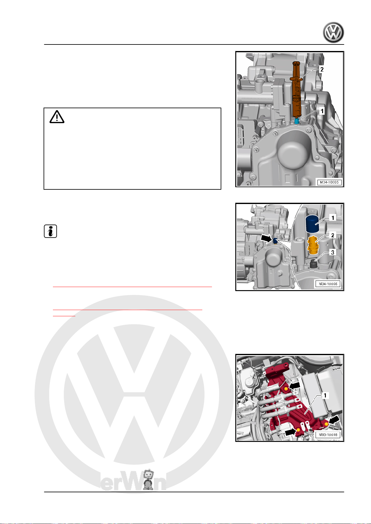
P
r
o
t
e
c
t
e
d
b
y
c
o
p
y
r
i
g
h
t
.
C
o
p
y
i
n
g
f
o
r
p
r
i
v
a
t
e
o
r
c
o
m
m
e
r
c
i
a
l
p
u
r
p
o
s
e
s
,
i
n
p
a
r
t
o
r
i
n
w
h
o
l
e
,
i
s
n
o
t
p
e
r
m
i
t
t
e
d
u
n
l
e
s
s
a
u
t
h
o
r
i
s
e
d
b
y
V
o
l
k
s
w
a
g
e
n
A
G
.
V
o
l
k
s
w
a
g
e
n
A
G
d
o
e
s
n
o
t
g
u
a
r
a
n
t
e
e
o
r
a
c
c
e
p
t
a
n
y
l
i
a
b
i
l
i
t
y
w
i
t
h
r
e
s
p
e
c
t
t
o
t
h
e
c
o
r
r
e
c
t
n
e
s
s
o
f
i
n
f
o
r
m
a
t
i
o
n
i
n
t
h
i
s
d
o
c
u
m
e
n
t
.
C
o
p
y
r
i
g
h
t
b
y
V
o
l
k
s
w
a
g
e
n
A
G
.
Direct Shift Gearbox - Edition 01.2016
• If more than 20 ml of hydraulic fluid leaked out, then 30 ml of
hydraulic fluid must be added via the vent -1- using the dis‐
posable syringe -2-.
• For the disposable syringe from the Repair Kit - 5C0 998 152and the correct hydraulic fluid. Refer to the Parts Catalog.
• Fill the new disposable syringe with 30 ml hydraulic fluid from
the new Power Steering Fluid - G 004 000 M2- container.
Caution
Risk of causing damage to the Mechatronic.
♦ Always use a new container to comply with cleanliness
requirements.
♦ Note the hydraulic fluid expiration date.
♦ Always use a new disposable syringe from the Repair Kit
- 5C0 998 152- . The disposable syringe must not be
reused.
– Push the new cap -1- on the ventilation -3-. It is replacement
part with a vent -2-.
Jetta Hybrid 2013 ➤
Note
If the Mechatronic is being replaced, install a sealing plug on the
old Mechatronic so that the fluid cannot leak out.
Assemble the rest in reverse order. Note the following:
– Fill the transmission fluid. Refer to
⇒ “7.1 Transmission Fluid, Draining and Filling”, page 111 .
– Check the adjustment of the selector lever cable; re-adjust if
necessary
⇒ “2.7 Selector Lever Cable, Checking and Adjusting”,
page 87 .
– Install the bracket -1- for the Electric Drive Power And Control
Electronics - JX1- -arrows-. Refer to ⇒ Electrical System Hy‐
brid; Rep. Gr. 93 ; High Voltage Cables; High Voltage Battery
High Voltage Cable Set, Removing and Installing .
– Install the high voltage cables bracket on the transmission
housing. Shown in illustration below, not called out.
Install the Electric Drive Power and Control Electronics - JX1- .
Refer to ⇒ Electrical Equipment; Rep. Gr. 93 ; Electric Drive
Power and Control Electronics; Electric Drive Power and Control
Electronics, Removing and Installing .
1. Mechatronic 67
Page 72
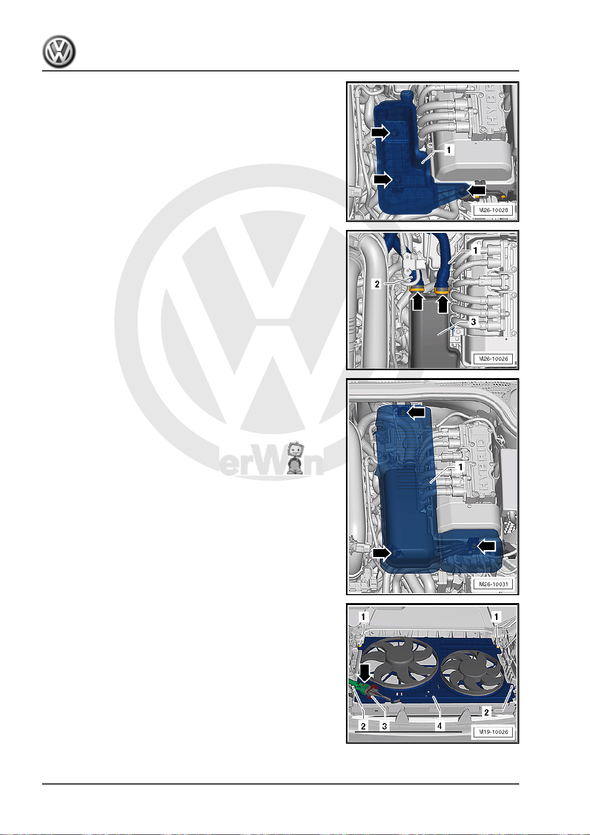
P
r
o
t
e
c
t
e
d
b
y
c
o
p
y
r
i
g
h
t
.
C
o
p
y
i
n
g
f
o
r
p
r
i
v
a
t
e
o
r
c
o
m
m
e
r
c
i
a
l
p
u
r
p
o
s
e
s
,
i
n
p
a
r
t
o
r
i
n
w
h
o
l
e
,
i
s
n
o
t
p
e
r
m
i
t
t
e
d
u
n
l
e
s
s
a
u
t
h
o
r
i
s
e
d
b
y
V
o
l
k
s
w
a
g
e
n
A
G
.
V
o
l
k
s
w
a
g
e
n
A
G
d
o
e
s
n
o
t
g
u
a
r
a
n
t
e
e
o
r
a
c
c
e
p
t
a
n
y
l
i
a
b
i
l
i
t
y
w
i
t
h
r
e
s
p
e
c
t
t
o
t
h
e
c
o
r
r
e
c
t
n
e
s
s
o
f
i
n
f
o
r
m
a
t
i
o
n
i
n
t
h
i
s
d
o
c
u
m
e
n
t
.
C
o
p
y
r
i
g
h
t
b
y
V
o
l
k
s
w
a
g
e
n
A
G
.
Jetta Hybrid 2013 ➤
Direct Shift Gearbox - Edition 01.2016
Vehicles with Secondary Air Injection (AIR) System
– Install the damper -1-.
– Attach the air line -1 and 2- to the damper -3-.
For All Vehicles
– Install the damper cover -1-.
– Connect the 12V battery. Refer to ⇒ Electrical Equipment;
Rep. Gr. 27 ; Battery, Disconnecting and Connecting .
– Reset the service position. Refer to ⇒ Body Exterior; Rep. Gr.
50 ; Lock Carrier; Service Position, Performing and Resetting .
– Install the fan shroud. Refer to ⇒ Rep. Gr. 19 ; Radiator/
Coolant Fan; Fan Shroud, Removing and Installing .
– Fill the engine coolant. Refer to ⇒ Rep. Gr. 19 ; Cooling Sys‐
tem/Coolant; Coolant, Draining and Filling .
– Install the noise insulation. Refer to ⇒ Body Exterior; Rep. Gr.
66 ; Overview - Noise Insulation .
– Energize the high voltage system and complete the required
documentation. Refer to ⇒ Electrical System Hybrid; Rep. Gr.
93 ; High Voltage System, Energizing .
68 Rep. Gr.34 - Controls, Housing
Page 73
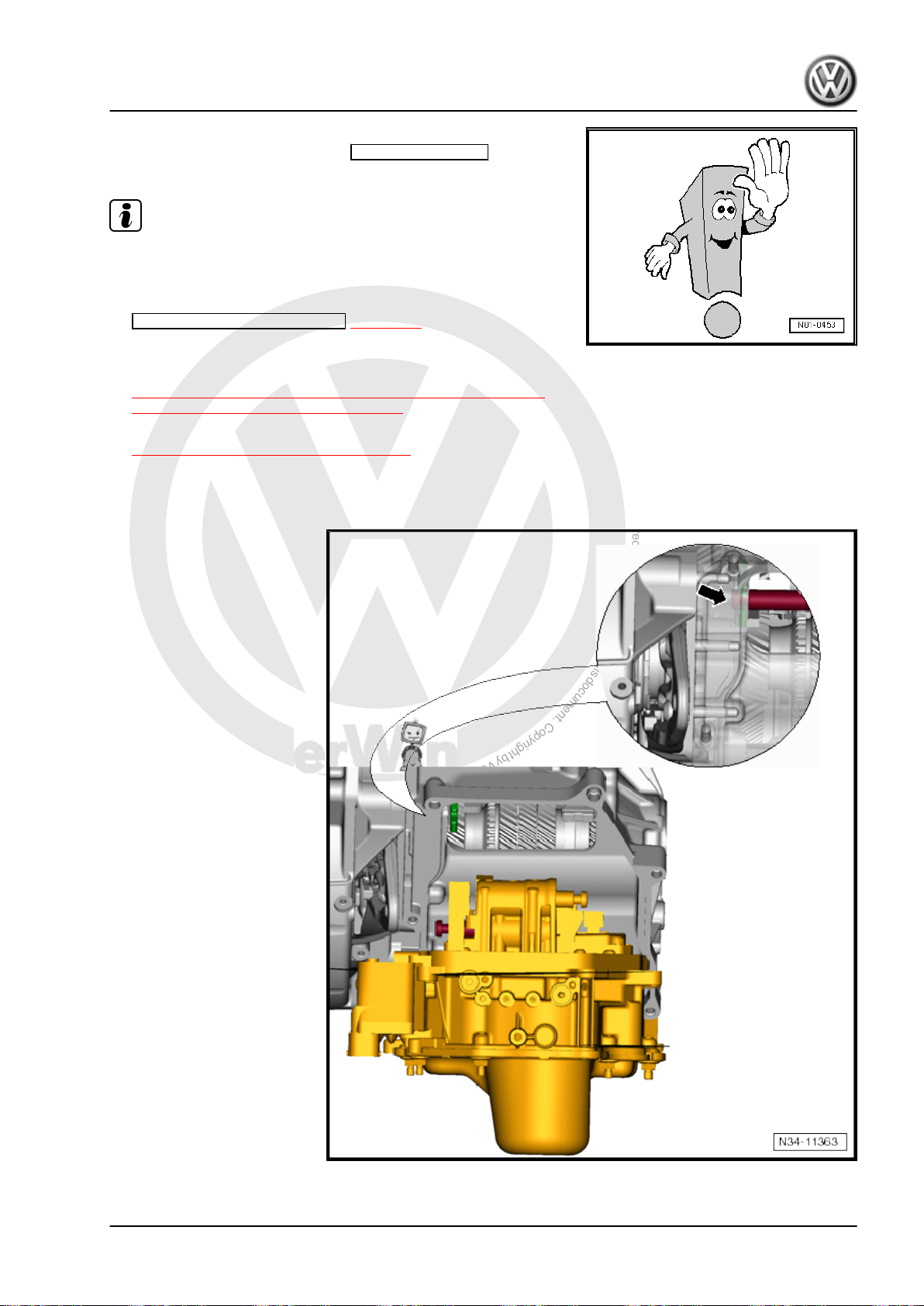
P
r
o
t
e
c
t
e
d
b
y
c
o
p
y
r
i
g
h
t
.
C
o
p
y
i
n
g
f
o
r
p
r
i
v
a
t
e
o
r
c
o
m
m
e
r
c
i
a
l
p
u
r
p
o
s
e
s
,
i
n
p
a
r
t
o
r
i
n
w
h
o
l
e
,
i
s
n
o
t
p
e
r
m
i
t
t
e
d
u
n
l
e
s
s
a
u
t
h
o
r
i
s
e
d
b
y
V
o
l
k
s
w
a
g
e
n
A
G
.
V
o
l
k
s
w
a
g
e
n
A
G
d
o
e
s
n
o
t
g
u
a
r
a
n
t
e
e
o
r
a
c
c
e
p
t
a
n
y
l
i
a
b
i
l
i
t
y
w
i
t
h
r
e
s
p
e
c
t
t
o
t
h
e
c
o
r
r
e
c
t
n
e
s
s
o
f
i
n
f
o
r
m
a
t
i
o
n
i
n
t
h
i
s
d
o
c
u
m
e
n
t
.
C
o
p
y
r
i
g
h
t
b
y
V
o
l
k
s
w
a
g
e
n
A
G
.
Direct Shift Gearbox - Edition 01.2016
• Bleed the hydraulic clutch mechanism for the decoupler using
the Vehicle Diagnostic Tester in Guided Functions after en‐
ergizing the high voltage system.
Note
The decoupler in Electro-Drive Drive Motor - V141- separates the
internal combustion engine from the Electro-Drive Drive Motor V141- .
– Perform basic measurement ⇒ page 10 .
Tightening Specifications
♦ Refer to
♦ For the hydraulic line bolt to the engine. Refer to
1.3 Mechatronic, Moving into Removal Position by Hand
⇒ Fig. ““ DSG Transmission Mechatronic -J743- - Tightening
Specification and Sequence”“ , page 50
⇒ “1.1 Overview - Mechatronic”, page 48 .
Jetta Hybrid 2013 ➤
1. Mechatronic 69
Page 74
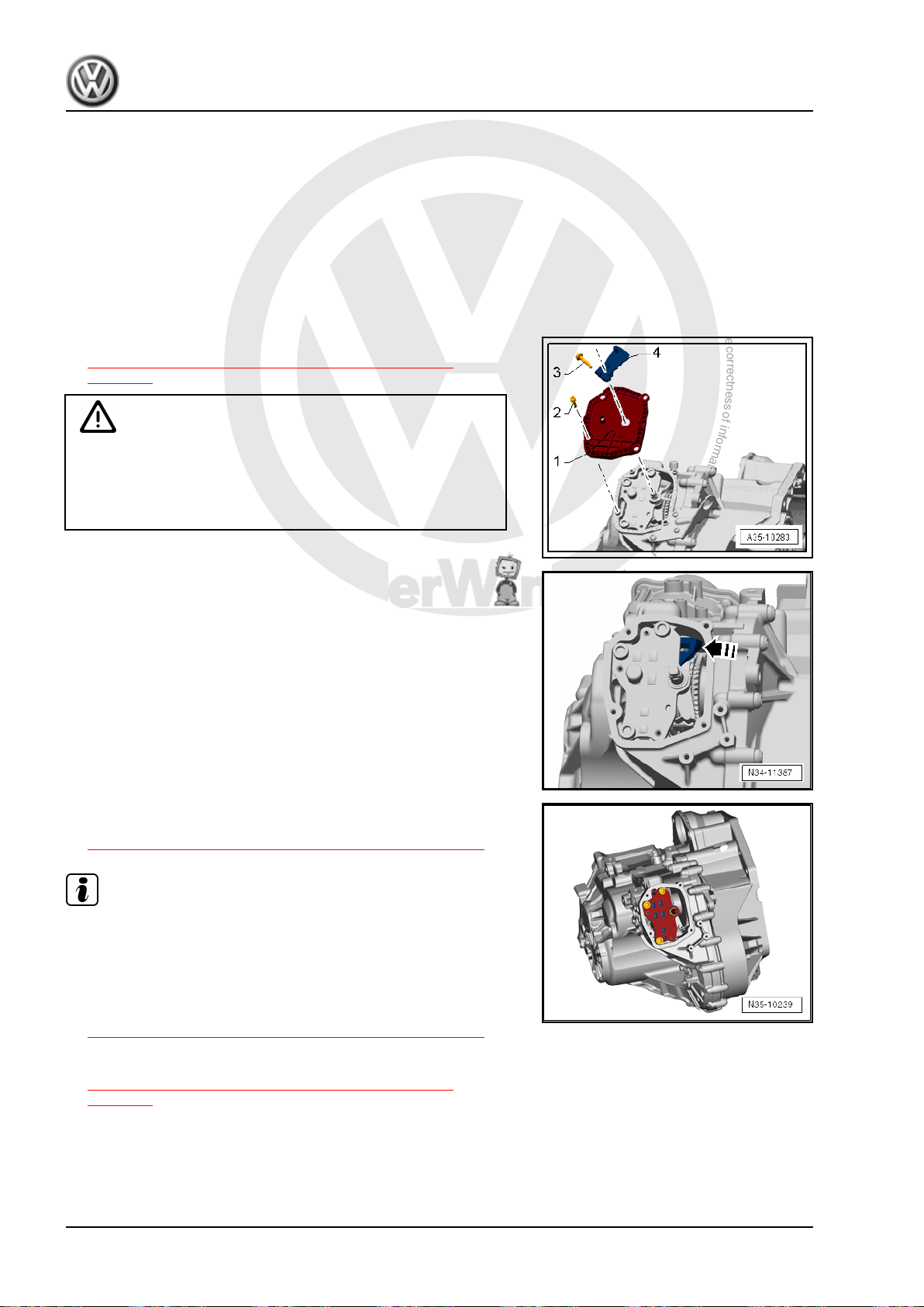
P
r
o
t
e
c
t
e
d
b
y
c
o
p
y
r
i
g
h
t
.
C
o
p
y
i
n
g
f
o
r
p
r
i
v
a
t
e
o
r
c
o
m
m
e
r
c
i
a
l
p
u
r
p
o
s
e
s
,
i
n
p
a
r
t
o
r
i
n
w
h
o
l
e
,
i
s
n
o
t
p
e
r
m
i
t
t
e
d
u
n
l
e
s
s
a
u
t
h
o
r
i
s
e
d
b
y
V
o
l
k
s
w
a
g
e
n
A
G
.
V
o
l
k
s
w
a
g
e
n
A
G
d
o
e
s
n
o
t
g
u
a
r
a
n
t
e
e
o
r
a
c
c
e
p
t
a
n
y
l
i
a
b
i
l
i
t
y
w
i
t
h
r
e
s
p
e
c
t
t
o
t
h
e
c
o
r
r
e
c
t
n
e
s
s
o
f
i
n
f
o
r
m
a
t
i
o
n
i
n
t
h
i
s
d
o
c
u
m
e
n
t
.
C
o
p
y
r
i
g
h
t
b
y
V
o
l
k
s
w
a
g
e
n
A
G
.
Jetta Hybrid 2013 ➤
Direct Shift Gearbox - Edition 01.2016
Procedure
It may not be possible to remove the Mechatronic. In this case,
the gear selector will get caught at the top on the left side on the
transmission housing -arrow-.
The gear selector that is caught must now be push into a removal
position by hand. It is necessary to remove the cover on the gear‐
shift shaft.
– Install the Mechatronic completely into the transmission and
secure it with a bolt.
– Move the selector lever into “P”.
– Remove the cover from the parking lock -1-. Refer to
⇒ “1.1 Parking Lock Cover, Removing and Installing”,
page 121 .
Caution
Danger of causing damage to the Mechatronic if it falls out.
♦ In the following procedure the Mechatronic is loose and
could fall. Secure the Mechatronic to the transmission with
1 bolt to prevent it from falling down.
– Push the shift fork to the side through the opening in direction
of -arrow-.
The gear selector that is caught will be pushed back and it will be
possible to remove the Mechatronic.
– Remove the Mechatronic.
– After completing the work on the Mechatronic and it is instal‐
led, fill the transmission fluid via the parking lock. Refer to
⇒ “7.1 Transmission Fluid, Draining and Filling”, page 111 .
Note
♦
When filling the transmission with transmission fluid via the
parking lock, it is not necessary to remove the transmission
bleed cap on the parking lock cover. It is possible to fill the
transmission fluid directly on the parking lock.
♦
Procedure, capacities and transmission fluid specification. Re‐
fer to
⇒ “7.1 Transmission Fluid, Draining and Filling”, page 111 .
– Install the cover for the parking lock -1-. Refer to
⇒ “1.1 Parking Lock Cover, Removing and Installing”,
page 121 .
70 Rep. Gr.34 - Controls, Housing
Page 75
P
r
o
t
e
c
t
e
d
b
y
c
o
p
y
r
i
g
h
t
.
C
o
p
y
i
n
g
f
o
r
p
r
i
v
a
t
e
o
r
c
o
m
m
e
r
c
i
a
l
p
u
r
p
o
s
e
s
,
i
n
p
a
r
t
o
r
i
n
w
h
o
l
e
,
i
s
n
o
t
p
e
r
m
i
t
t
e
d
u
n
l
e
s
s
a
u
t
h
o
r
i
s
e
d
b
y
V
o
l
k
s
w
a
g
e
n
A
G
.
V
o
l
k
s
w
a
g
e
n
A
G
d
o
e
s
n
o
t
g
u
a
r
a
n
t
e
e
o
r
a
c
c
e
p
t
a
n
y
l
i
a
b
i
l
i
t
y
w
i
t
h
r
e
s
p
e
c
t
t
o
t
h
e
c
o
r
r
e
c
t
n
e
s
s
o
f
i
n
f
o
r
m
a
t
i
o
n
i
n
t
h
i
s
d
o
c
u
m
e
n
t
.
C
o
p
y
r
i
g
h
t
b
y
V
o
l
k
s
w
a
g
e
n
A
G
.
2 Selector Mechanism
⇒ “2.1 Overview - Selector Mechanism”, page 71
⇒ “2.2 Emergency Release from P”, page 73
⇒ “2.3 Selector Lever Handle, Removing and Installing”,
page 74
⇒ “2.4 Button in Handle, Moving Into Installation Position”,
page 75
⇒ “2.5 Selector Mechanism, Removing and Installing”,
page 77
⇒ “2.6 Gearshift Mechanism, Checking”, page 86
⇒ “2.7 Selector Lever Cable, Checking and Adjusting”,
page 87
⇒ “2.8 Selector Shaft Seal, Replacing”, page 90
2.1 Overview - Selector Mechanism
WARNING
Move the selector lever into “P” and set the parking brake be‐
fore working with the engine running.
Jetta Hybrid 2013 ➤
Direct Shift Gearbox - Edition 01.2016
2. Selector Mechanism 71
Page 76
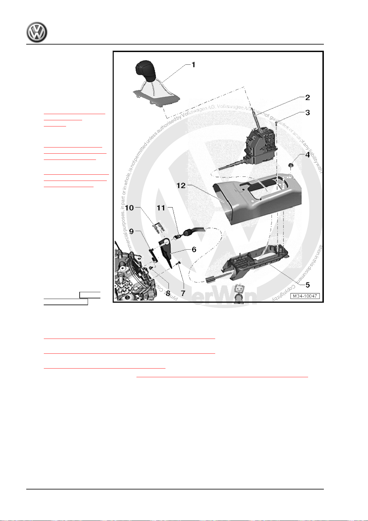
P
r
o
t
e
c
t
e
d
b
y
c
o
p
y
r
i
g
h
t
.
C
o
p
y
i
n
g
f
o
r
p
r
i
v
a
t
e
o
r
c
o
m
m
e
r
c
i
a
l
p
u
r
p
o
s
e
s
,
i
n
p
a
r
t
o
r
i
n
w
h
o
l
e
,
i
s
n
o
t
p
e
r
m
i
t
t
e
d
u
n
l
e
s
s
a
u
t
h
o
r
i
s
e
d
b
y
V
o
l
k
s
w
a
g
e
n
A
G
.
V
o
l
k
s
w
a
g
e
n
A
G
d
o
e
s
n
o
t
g
u
a
r
a
n
t
e
e
o
r
a
c
c
e
p
t
a
n
y
l
i
a
b
i
l
i
t
y
w
i
t
h
r
e
s
p
e
c
t
t
o
t
h
e
c
o
r
r
e
c
t
n
e
s
s
o
f
i
n
f
o
r
m
a
t
i
o
n
i
n
t
h
i
s
d
o
c
u
m
e
n
t
.
C
o
p
y
r
i
g
h
t
b
y
V
o
l
k
s
w
a
g
e
n
A
G
.
Jetta Hybrid 2013 ➤
Direct Shift Gearbox - Edition 01.2016
1 - Selector Lever Handle
❑ With selector lever boot
and cover
❑ Do not remove the han‐
dle unnecessarily.
❑ Only the cover needs to
be unclipped for emer‐
gency release. Refer to
⇒ “2.2 Emergency Re‐
lease from P”,
page 73
❑ Removing and instal‐
ling. Refer to
⇒ “2.3 Selector Lever
Handle, Removing and
Installing”, page 74 .
❑ Refer to
⇒ “2.4 Button in Handle,
Moving Into Installation
Position”, page 75
2 - Selector Mechanism with
Selector Lever Cable
❑ With a permanent circuit
board for the selector
mechanism
❑ With integrated Selector
Lever - E313- with Se‐
lector Lever Sensor
System Control Module
- J587- , Tiptronic
Switch - F189- , Selector
Lever Park Position
Lock Switch - F319- and
Shift Lock Solenoid N110- .
❑ Check using Guided
Fault Finding. Refer
to Vehicle Diagnostic Tester
❑ The Selector Lever - E313- with the Selector Lever Sensor System Control Module - J587- , Tiptronic
Switch - F189- , Selector Lever Park Position Lock Switch - F319- and Shift Lock Solenoid - N110- can
only be replaced completely with the selector mechanism. Refer to
⇒ “2.5 Selector Mechanism, Removing and Installing”, page 77 .
❑ Selector lever cable can only be replaced with the selector mechanism. Refer to
⇒ “2.5 Selector Mechanism, Removing and Installing”, page 77 .
❑ Perform selector mechanism emergency release. Refer to
⇒ “2.2 Emergency Release from P”, page 73 .
❑ Removing and installing. Refer to ⇒ “2.5 Selector Mechanism, Removing and Installing”, page 77 .
❑ Do not lubricate the selector lever cable
3 - Bolt
❑ 4 Nm
❑ For attaching the selector mechanism to the selector housing
❑ Quantity: 4
4 - Nut
❑ 8 Nm
❑ Quantity: 4
❑ For selector mechanism to body
72 Rep. Gr.34 - Controls, Housing
Page 77

P
r
o
t
e
c
t
e
d
b
y
c
o
p
y
r
i
g
h
t
.
C
o
p
y
i
n
g
f
o
r
p
r
i
v
a
t
e
o
r
c
o
m
m
e
r
c
i
a
l
p
u
r
p
o
s
e
s
,
i
n
p
a
r
t
o
r
i
n
w
h
o
l
e
,
i
s
n
o
t
p
e
r
m
i
t
t
e
d
u
n
l
e
s
s
a
u
t
h
o
r
i
s
e
d
b
y
V
o
l
k
s
w
a
g
e
n
A
G
.
V
o
l
k
s
w
a
g
e
n
A
G
d
o
e
s
n
o
t
g
u
a
r
a
n
t
e
e
o
r
a
c
c
e
p
t
a
n
y
l
i
a
b
i
l
i
t
y
w
i
t
h
r
e
s
p
e
c
t
t
o
t
h
e
c
o
r
r
e
c
t
n
e
s
s
o
f
i
n
f
o
r
m
a
t
i
o
n
i
n
t
h
i
s
d
o
c
u
m
e
n
t
.
C
o
p
y
r
i
g
h
t
b
y
V
o
l
k
s
w
a
g
e
n
A
G
.
5 - Selector Housing
6 - Cable Mounting Bracket
❑ For selector lever cable
7 - Bolt
❑ 8 Nm +90° turn
❑ Replace after removing
❑ For attaching the cable bracket to the transmission
❑ Quantity: 3
8 - Bolt
❑ 10 Nm +90°
❑ Replace after removing
❑ For the transmission shift lever
9 - Gearshift Lever
10 - Lock Washer
❑ For attaching the selector lever cable to the cable bracket
❑ Replacing
Note
Jetta Hybrid 2013 ➤
Direct Shift Gearbox - Edition 01.2016
The lock washer fit very tightly on
the cable bracket. If necessary, re‐
move the cable bracket and selector
lever cable from the transmission.
Refer to ⇒ page 80 .
11 - Bolt
12 - Tunnel/Body
2.2 Emergency Release from P
Do Not Remove the Handle
♦ The Shift Lock Solenoid - N110- locks the selector lever in the
♦ It is not possible to move the selector lever out of “P” if the
If this is not the case:
❑ 13 Nm
❑ Selector lever cable adjusting screw
position “P”. The selector lever can be shifted out of “P ” with
ignition on or motor start, separate brake pedal and pressed
button on the selector lever head. Refer to
⇒ “2.6 Gearshift Mechanism, Checking”, page 86 .
voltage supply to the Shift Lock Solenoid - N110- is interrupted
(the battery is discharged or a fuse is faulty) or if the solenoid
is faulty. The vehicle cannot be moved because the parking
lock is set.
– Check the fuses. Refer to ⇒ Wiring diagrams, Troubleshooting
& Component locations.
– Check the battery voltage. Refer to ⇒ Electrical Equipment;
Rep. Gr. 27 ; Battery; Battery, Checking .
2. Selector Mechanism 73
Page 78
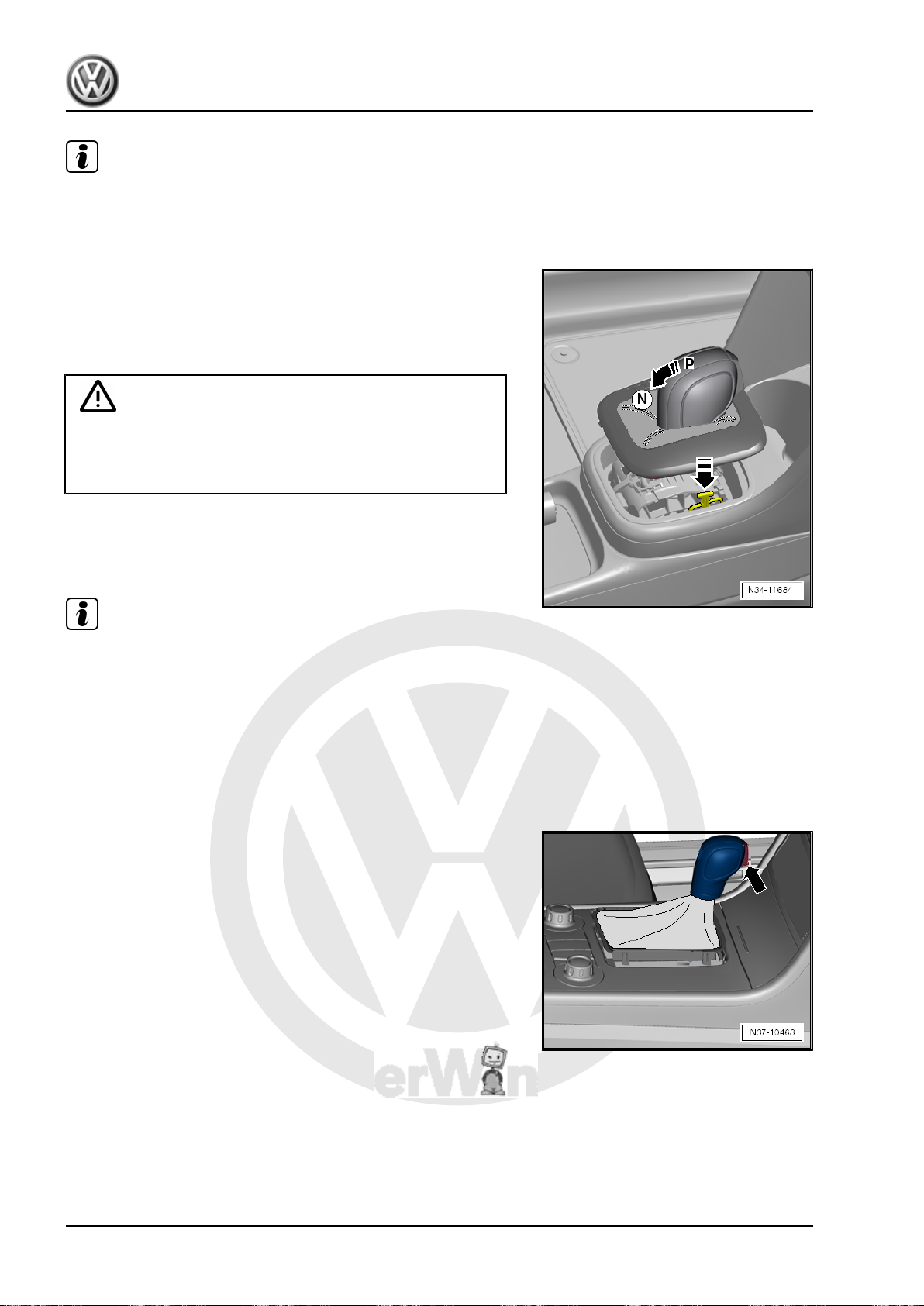
P
r
o
t
e
c
t
e
d
b
y
c
o
p
y
r
i
g
h
t
.
C
o
p
y
i
n
g
f
o
r
p
r
i
v
a
t
e
o
r
c
o
m
m
e
r
c
i
a
l
p
u
r
p
o
s
e
s
,
i
n
p
a
r
t
o
r
i
n
w
h
o
l
e
,
i
s
n
o
t
p
e
r
m
i
t
t
e
d
u
n
l
e
s
s
a
u
t
h
o
r
i
s
e
d
b
y
V
o
l
k
s
w
a
g
e
n
A
G
.
V
o
l
k
s
w
a
g
e
n
A
G
d
o
e
s
n
o
t
g
u
a
r
a
n
t
e
e
o
r
a
c
c
e
p
t
a
n
y
l
i
a
b
i
l
i
t
y
w
i
t
h
r
e
s
p
e
c
t
t
o
t
h
e
c
o
r
r
e
c
t
n
e
s
s
o
f
i
n
f
o
r
m
a
t
i
o
n
i
n
t
h
i
s
d
o
c
u
m
e
n
t
.
C
o
p
y
r
i
g
h
t
b
y
V
o
l
k
s
w
a
g
e
n
A
G
.
Jetta Hybrid 2013 ➤
Direct Shift Gearbox - Edition 01.2016
Note
If the selector lever still cannot switch out of “P”, the emergency
release of the solenoid must be executed. If the selector lever is
then switched back into “P”, this is locked again in the position
“P”.
Procedure
– Unclip the selector lever cover and move it to the side.
– Press the brake or set the parking brake.
– Push onto the yellow plastic part in direction of -arrow-.
Caution
The selector mechanism could get damaged.
♦ The selector mechanism must be replaced completely if
any of its components are damaged.
• The solenoid releases the selector lever.
– When the solenoid is free, press the button in the selector lever
handle and move the selector lever out of “P”.
Note
If the selector lever is not switched back into “P”, the solenoid for
the shift block will be automatically blocked in the position “P”.
The solenoid must be released again.
2.3 Selector Lever Handle, Removing and Installing
Special tools and workshop equipment required
♦ Trim Removal Wedge - 3409-
Removing
The handle and selector lever cover are removed.
– Move the selector lever into “D”.
– Turn off the ignition.
– Unclip the cover on both sides using Trim Removal Wedge -
3409- and remove it.
– Remove the connector from the selector lever cover.
– Push the sleeve upward in direction of -arrow- to unlock the
handle.
74 Rep. Gr.34 - Controls, Housing
Page 79
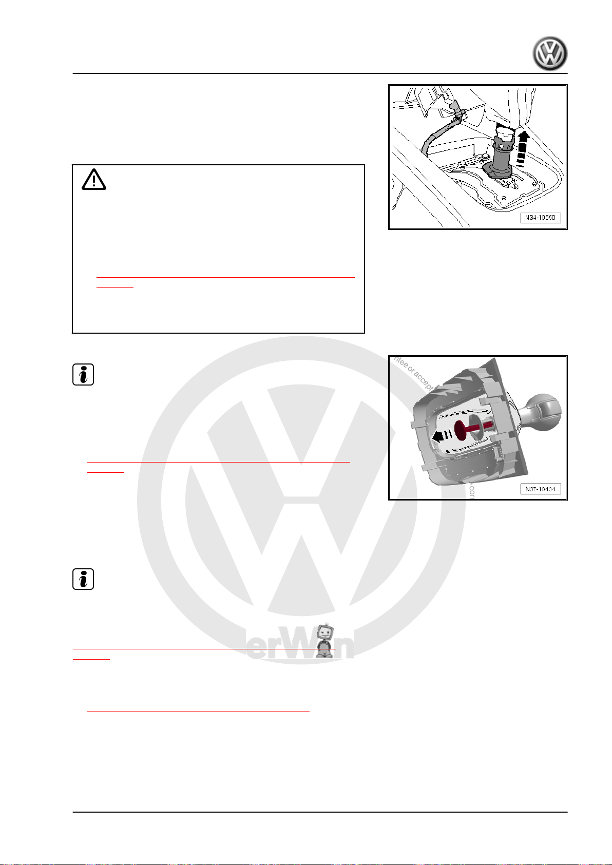
P
r
o
t
e
c
t
e
d
b
y
c
o
p
y
r
i
g
h
t
.
C
o
p
y
i
n
g
f
o
r
p
r
i
v
a
t
e
o
r
c
o
m
m
e
r
c
i
a
l
p
u
r
p
o
s
e
s
,
i
n
p
a
r
t
o
r
i
n
w
h
o
l
e
,
i
s
n
o
t
p
e
r
m
i
t
t
e
d
u
n
l
e
s
s
a
u
t
h
o
r
i
s
e
d
b
y
V
o
l
k
s
w
a
g
e
n
A
G
.
V
o
l
k
s
w
a
g
e
n
A
G
d
o
e
s
n
o
t
g
u
a
r
a
n
t
e
e
o
r
a
c
c
e
p
t
a
n
y
l
i
a
b
i
l
i
t
y
w
i
t
h
r
e
s
p
e
c
t
t
o
t
h
e
c
o
r
r
e
c
t
n
e
s
s
o
f
i
n
f
o
r
m
a
t
i
o
n
i
n
t
h
i
s
d
o
c
u
m
e
n
t
.
C
o
p
y
r
i
g
h
t
b
y
V
o
l
k
s
w
a
g
e
n
A
G
.
Direct Shift Gearbox - Edition 01.2016
– Pull the selector lever handle and cover upward without press‐
ing the button.
Installing
Install in reverse order of removal. Note the following:
• The selector lever is in the “D” position.
Caution
The selector mechanism could get damaged.
♦ The button on the selector lever handle must be extended
when installing. If the button should get pushed in unin‐
tentionally while the selector lever handle is removed, then
it must be brought back into its installation position. Refer
to
⇒ “2.4 Button in Handle, Moving Into Installation Position”,
page 75 .
♦ The selector lever handle and the pull rod -3- on the se‐
lector mechanism will get damaged if the selector lever
handle is installed with the button pushed in.
Note
♦
A new handle is delivered with an assembly fastener. Pull out
the safety catch in direction of -arrow- just before installing the
new handle.
♦
The installed position can be set again using the assembly
safety catch. Refer to
⇒ “2.4 Button in Handle, Moving Into Installation Position”,
page 75 .
– Push the selector lever handle -1- all the way onto the selector
lever without pushing the button while doing this.
– Lock the handle again after installing it. Push the sleeve down‐
ward under the handle.
– Press the button after installing it.
Note
If the button stays in the handle after being pressed, this means
it was installed incorrectly. If this happens, remove the handle
again and move the button in the installation position again. Refer
to
⇒ “2.4 Button in Handle, Moving Into Installation Position”,
page 75 . Then install the handle again.
– Fold the boot downward and attach it.
– Check the selector mechanism. Refer to
⇒ “2.6 Gearshift Mechanism, Checking”, page 86 .
Jetta Hybrid 2013 ➤
2.4 Button in Handle, Moving Into Installa‐
tion Position
If the button was pushed in by mistake, the installed position can
be set again.
2. Selector Mechanism 75
Page 80
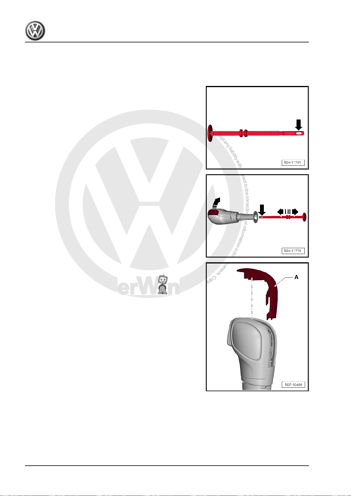
P
r
o
t
e
c
t
e
d
b
y
c
o
p
y
r
i
g
h
t
.
C
o
p
y
i
n
g
f
o
r
p
r
i
v
a
t
e
o
r
c
o
m
m
e
r
c
i
a
l
p
u
r
p
o
s
e
s
,
i
n
p
a
r
t
o
r
i
n
w
h
o
l
e
,
i
s
n
o
t
p
e
r
m
i
t
t
e
d
u
n
l
e
s
s
a
u
t
h
o
r
i
s
e
d
b
y
V
o
l
k
s
w
a
g
e
n
A
G
.
V
o
l
k
s
w
a
g
e
n
A
G
d
o
e
s
n
o
t
g
u
a
r
a
n
t
e
e
o
r
a
c
c
e
p
t
a
n
y
l
i
a
b
i
l
i
t
y
w
i
t
h
r
e
s
p
e
c
t
t
o
t
h
e
c
o
r
r
e
c
t
n
e
s
s
o
f
i
n
f
o
r
m
a
t
i
o
n
i
n
t
h
i
s
d
o
c
u
m
e
n
t
.
C
o
p
y
r
i
g
h
t
b
y
V
o
l
k
s
w
a
g
e
n
A
G
.
Jetta Hybrid 2013 ➤
Direct Shift Gearbox - Edition 01.2016
There are two ways to move the button into the installation posi‐
tion, »with« or »without« assembly fastener. The following de‐
scribes both ways.
Moving the Handle »with« an Assembly Fastener into the Instal‐
lation Position
Make sure the assembly fastener has an eye -arrow- at the front.
Other assembly fasteners cannot be used.
– Press the button and push the assembly fastener (with the
eye) -arrow- all the way in until it latches into place. Then re‐
lease the button. The button locks into the installation position
when the assembly fastener is pulled out.
Moving the Handle »without« an Assembly Fastener into the In‐
stallation Position
– Remove the trim -A- from the handle.
76 Rep. Gr.34 - Controls, Housing
Page 81
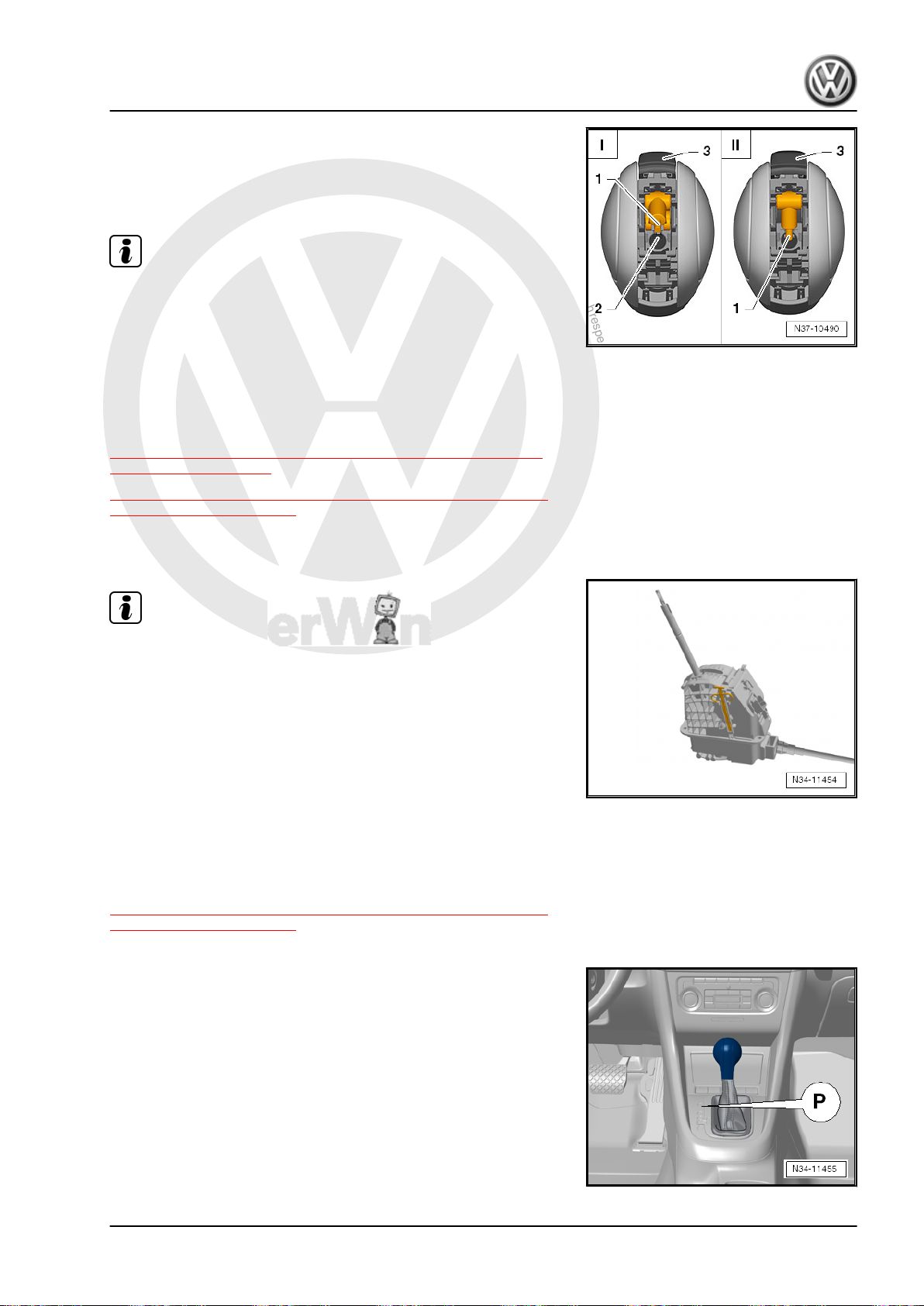
P
r
o
t
e
c
t
e
d
b
y
c
o
p
y
r
i
g
h
t
.
C
o
p
y
i
n
g
f
o
r
p
r
i
v
a
t
e
o
r
c
o
m
m
e
r
c
i
a
l
p
u
r
p
o
s
e
s
,
i
n
p
a
r
t
o
r
i
n
w
h
o
l
e
,
i
s
n
o
t
p
e
r
m
i
t
t
e
d
u
n
l
e
s
s
a
u
t
h
o
r
i
s
e
d
b
y
V
o
l
k
s
w
a
g
e
n
A
G
.
V
o
l
k
s
w
a
g
e
n
A
G
d
o
e
s
n
o
t
g
u
a
r
a
n
t
e
e
o
r
a
c
c
e
p
t
a
n
y
l
i
a
b
i
l
i
t
y
w
i
t
h
r
e
s
p
e
c
t
t
o
t
h
e
c
o
r
r
e
c
t
n
e
s
s
o
f
i
n
f
o
r
m
a
t
i
o
n
i
n
t
h
i
s
d
o
c
u
m
e
n
t
.
C
o
p
y
r
i
g
h
t
b
y
V
o
l
k
s
w
a
g
e
n
A
G
.
Jetta Hybrid 2013 ➤
Direct Shift Gearbox - Edition 01.2016
– Push the small lever -1- into the groove -2- with a screwdriver.
This pushes the button -3- into the installation position.
-I- the button is in the pressed position
-II- the button is in the installation position
♦
Push the lever into the groove and no further.
♦
Install the trim back onto the selector mechanism only after the
handle is installed. This way it is possible to see if the small
lever fits into the pull rod when the button is pushed.
2.5 Selector Mechanism, Removing and In‐
⇒ “2.5.1 Selector Mechanism with Selector Housing, Removing
and Installing”, page 77
⇒ “2.5.2 Selector Mechanism without Selector Housing, Remov‐
ing and Installing”, page 82
Special tools and workshop equipment required
♦ Pry Lever - 80-200-
♦
The selector mechanism and the selector lever cable cannot
Note
Note
stalling
be separated from each other. Both are removed at the same
time.
♦
After installation, the selector lever cable movement must be
checked and adjusted.
2.5.1 Selector Mechanism with Selector Housing, Removing and Installing
It is possible to remove and install the selector mechanism with
selector lever cable alone without the selector housing. Refer to
⇒ “2.5.2 Selector Mechanism without Selector Housing, Remov‐
ing and Installing”, page 82 .
Removing
– Move the selector lever into “P”.
2. Selector Mechanism 77
Page 82
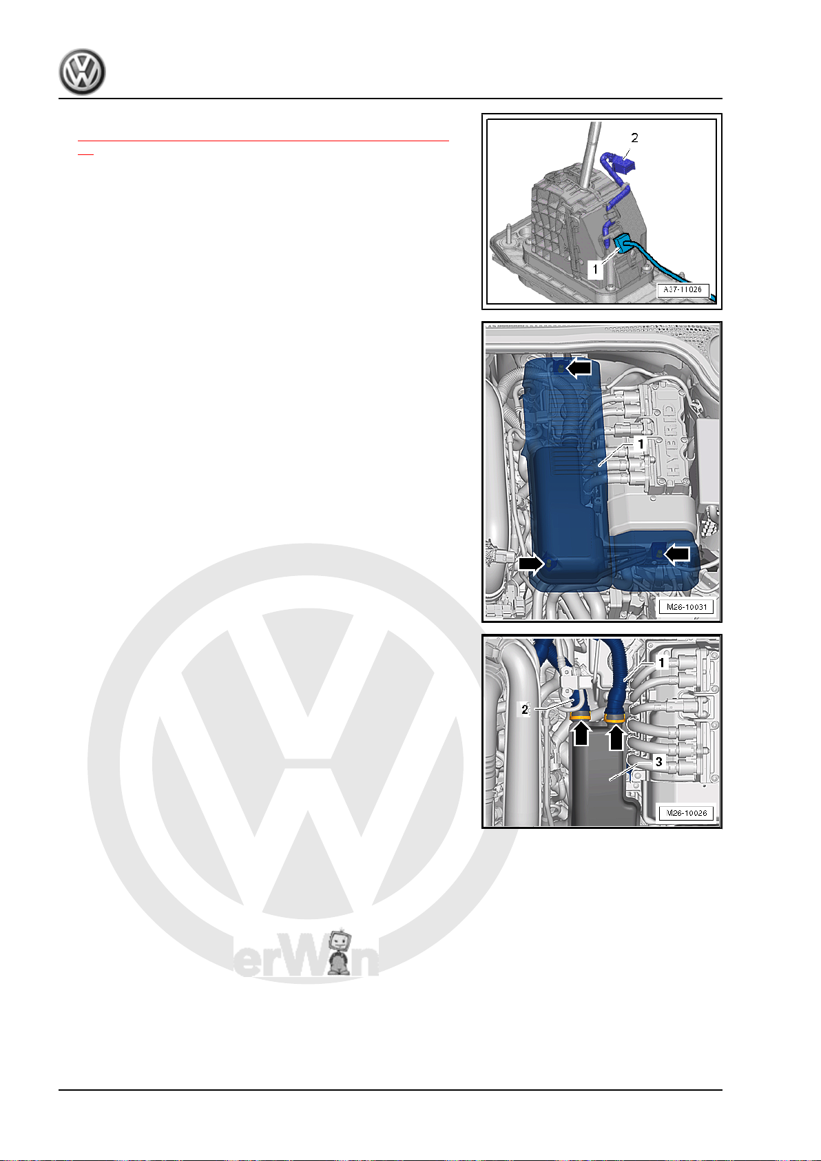
P
r
o
t
e
c
t
e
d
b
y
c
o
p
y
r
i
g
h
t
.
C
o
p
y
i
n
g
f
o
r
p
r
i
v
a
t
e
o
r
c
o
m
m
e
r
c
i
a
l
p
u
r
p
o
s
e
s
,
i
n
p
a
r
t
o
r
i
n
w
h
o
l
e
,
i
s
n
o
t
p
e
r
m
i
t
t
e
d
u
n
l
e
s
s
a
u
t
h
o
r
i
s
e
d
b
y
V
o
l
k
s
w
a
g
e
n
A
G
.
V
o
l
k
s
w
a
g
e
n
A
G
d
o
e
s
n
o
t
g
u
a
r
a
n
t
e
e
o
r
a
c
c
e
p
t
a
n
y
l
i
a
b
i
l
i
t
y
w
i
t
h
r
e
s
p
e
c
t
t
o
t
h
e
c
o
r
r
e
c
t
n
e
s
s
o
f
i
n
f
o
r
m
a
t
i
o
n
i
n
t
h
i
s
d
o
c
u
m
e
n
t
.
C
o
p
y
r
i
g
h
t
b
y
V
o
l
k
s
w
a
g
e
n
A
G
.
Jetta Hybrid 2013 ➤
Direct Shift Gearbox - Edition 01.2016
– Remove the selector lever handle. Refer to
⇒ “2.3 Selector Lever Handle, Removing and Installing”, page
74 . Disconnect the connector -2- from the cover while doing
this.
– Remove the center console. Refer to ⇒ Body Interior; Rep.
Gr. 68 ; Center Console; Center Console, Removing and In‐
stalling .
– Disconnect the connector -1- from the selector mechanism to
the vehicle wiring harness.
– Unclip and remove the damper cover -1- upward from the re‐
tainers -arrows-.
Vehicles with Secondary Air Injection (AIR) System
– Squeeze the locking ring -arrows- on both sides and remove
the air lines -1 and 2- from the damper -3-.
78 Rep. Gr.34 - Controls, Housing
Page 83
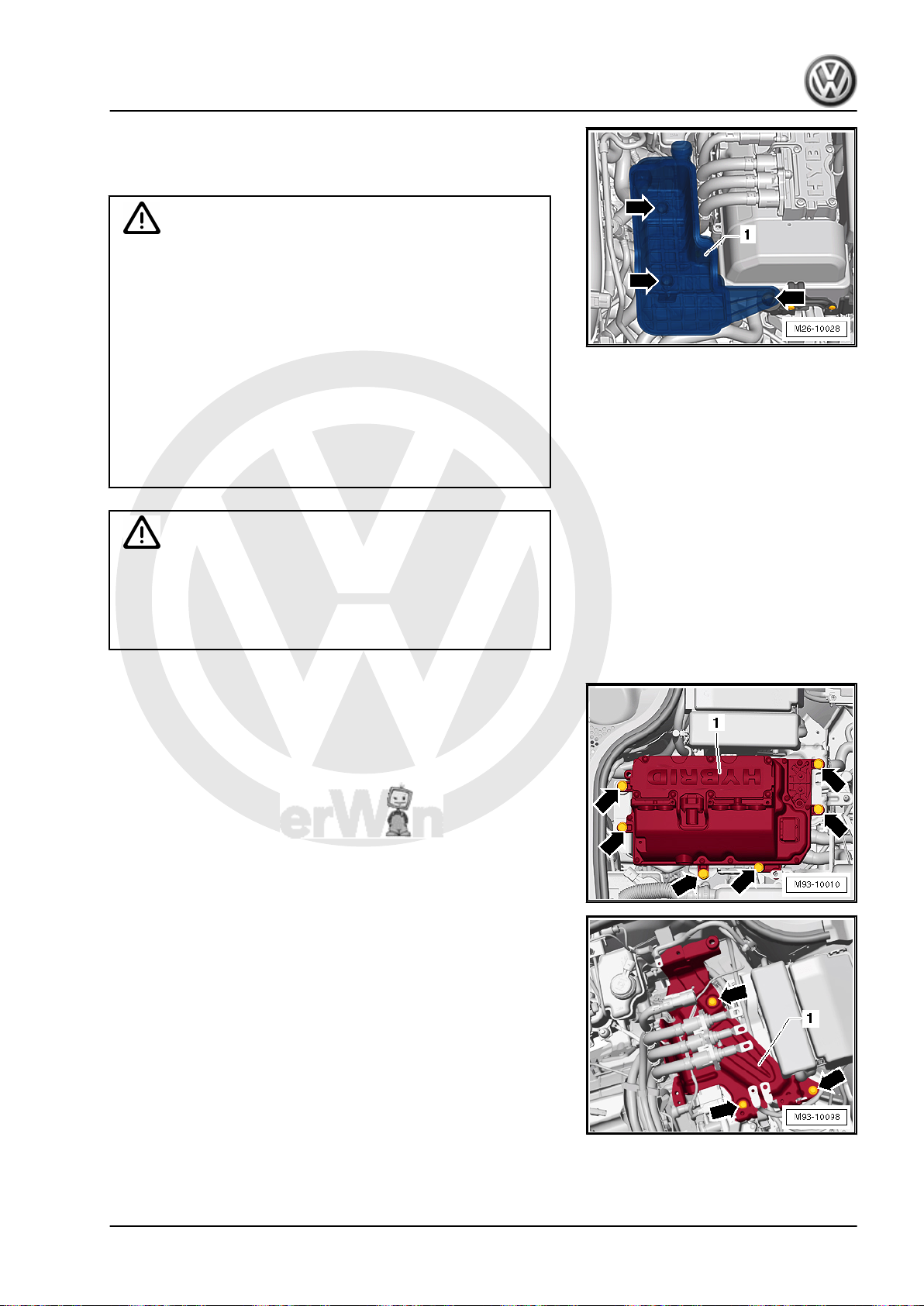
P
r
o
t
e
c
t
e
d
b
y
c
o
p
y
r
i
g
h
t
.
C
o
p
y
i
n
g
f
o
r
p
r
i
v
a
t
e
o
r
c
o
m
m
e
r
c
i
a
l
p
u
r
p
o
s
e
s
,
i
n
p
a
r
t
o
r
i
n
w
h
o
l
e
,
i
s
n
o
t
p
e
r
m
i
t
t
e
d
u
n
l
e
s
s
a
u
t
h
o
r
i
s
e
d
b
y
V
o
l
k
s
w
a
g
e
n
A
G
.
V
o
l
k
s
w
a
g
e
n
A
G
d
o
e
s
n
o
t
g
u
a
r
a
n
t
e
e
o
r
a
c
c
e
p
t
a
n
y
l
i
a
b
i
l
i
t
y
w
i
t
h
r
e
s
p
e
c
t
t
o
t
h
e
c
o
r
r
e
c
t
n
e
s
s
o
f
i
n
f
o
r
m
a
t
i
o
n
i
n
t
h
i
s
d
o
c
u
m
e
n
t
.
C
o
p
y
r
i
g
h
t
b
y
V
o
l
k
s
w
a
g
e
n
A
G
.
– Remove the damper -1- upward from the rubber bushings
-arrows-.
For All Vehicles
WARNING
Beware of the danger of electrocution.
An electrical shock can result in death.
Follow the High Voltage System General Warnings. Refer to
⇒ Electrical System Hybrid; Rep. Gr. 93 ; High Voltage System
General Warnings .
♦ A high voltage technician must de-energize the high volt‐
age system before any work can be performed on the high
WARNING
voltage system or before any servicing work can be per‐
formed on the body.
♦ Only hybrid electrically instructed persons may perform all
work on a vehicle with a high voltage system. All work
must be performed by a high voltage technician.
High voltage at the high voltage system of the hybrid vehicle.
Danger of electrocution! The following procedure requires
work on the high voltage system. To de-energize the high volt‐
age system. Refer to ⇒ Hybrid Electrical System; Rep. Gr.
93 ; High Voltage System, De-energizing .
– Remove the Electric Drive Power and Control Electronics -
JX1- . Refer to ⇒ Electrical Equipment; Rep. Gr. 93 ; Electric
Drive Power and Control Electronics; Electric Drive Power and
Control Electronics, Removing and Installing .
Jetta Hybrid 2013 ➤
Direct Shift Gearbox - Edition 01.2016
– Remove the bracket -1- for the Electric Drive Power And Con‐
trol Electronics - JX1- -arrows-. Refer to ⇒ Electrical System
Hybrid; Rep. Gr. 93 ; High Voltage Cables; High Voltage Bat‐
tery High Voltage Cable Set, Removing and Installing .
2. Selector Mechanism 79
Page 84
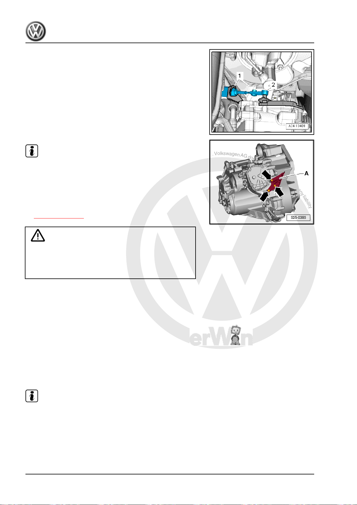
P
r
o
t
e
c
t
e
d
b
y
c
o
p
y
r
i
g
h
t
.
C
o
p
y
i
n
g
f
o
r
p
r
i
v
a
t
e
o
r
c
o
m
m
e
r
c
i
a
l
p
u
r
p
o
s
e
s
,
i
n
p
a
r
t
o
r
i
n
w
h
o
l
e
,
i
s
n
o
t
p
e
r
m
i
t
t
e
d
u
n
l
e
s
s
a
u
t
h
o
r
i
s
e
d
b
y
V
o
l
k
s
w
a
g
e
n
A
G
.
V
o
l
k
s
w
a
g
e
n
A
G
d
o
e
s
n
o
t
g
u
a
r
a
n
t
e
e
o
r
a
c
c
e
p
t
a
n
y
l
i
a
b
i
l
i
t
y
w
i
t
h
r
e
s
p
e
c
t
t
o
t
h
e
c
o
r
r
e
c
t
n
e
s
s
o
f
i
n
f
o
r
m
a
t
i
o
n
i
n
t
h
i
s
d
o
c
u
m
e
n
t
.
C
o
p
y
r
i
g
h
t
b
y
V
o
l
k
s
w
a
g
e
n
A
G
.
Jetta Hybrid 2013 ➤
Direct Shift Gearbox - Edition 01.2016
– Remove the lock washer -1- from the selector lever cable.
Always replace the circlip on the selector lever cable.
– Remove the selector lever cable -2- from the selector lever,
for example, with Pry Lever - 80-200- .
Note
♦
Use pliers to remove the lock washer -1-. Do not use a sharpedged lever. Otherwise the selector lever cable could get
damaged.
♦
Remove the cable bracket -A- and selector lever cable from
the transmission, if necessary. To do this, remove the bolts
-arrows-. These bolts must be replaced.
♦
Bolt tightening specification -arrows- -item 7-
⇒ Item 7 (page 73) .
Caution
Danger of damaging the selector lever cable.
♦ Push the selector lever cable to the rear and out of the
cable bracket. Guide the selector lever cable out of the
cable bracket when removing the selector mechanism.
– Lift the vehicle.
– Remove the front and rear tunnel braces from the body. Refer
to ⇒ Body Exterior; Rep. Gr. 50 ; Tunnel Bridge .
– Remove the exhaust pipe under the center tunnel heat shield.
Refer to ⇒ Engine Mechanical, Fuel Injection and Ignition;
Rep. Gr. 26 ; Overview - Emissions Control .
– Disconnect the center and rear mufflers from the retaining
straps and tie them to the body with wire. Refer to ⇒ Engine
Mechanical, Fuel Injection and Ignition; Rep. Gr. 26 ; Exhaust
Pipes/Mufflers; Overview - Muffler .
– Remove the center tunnel heat shield under the selector
mechanism.
Note
A second technician is required under the vehicle to remove the
selector mechanism.
80 Rep. Gr.34 - Controls, Housing
Page 85
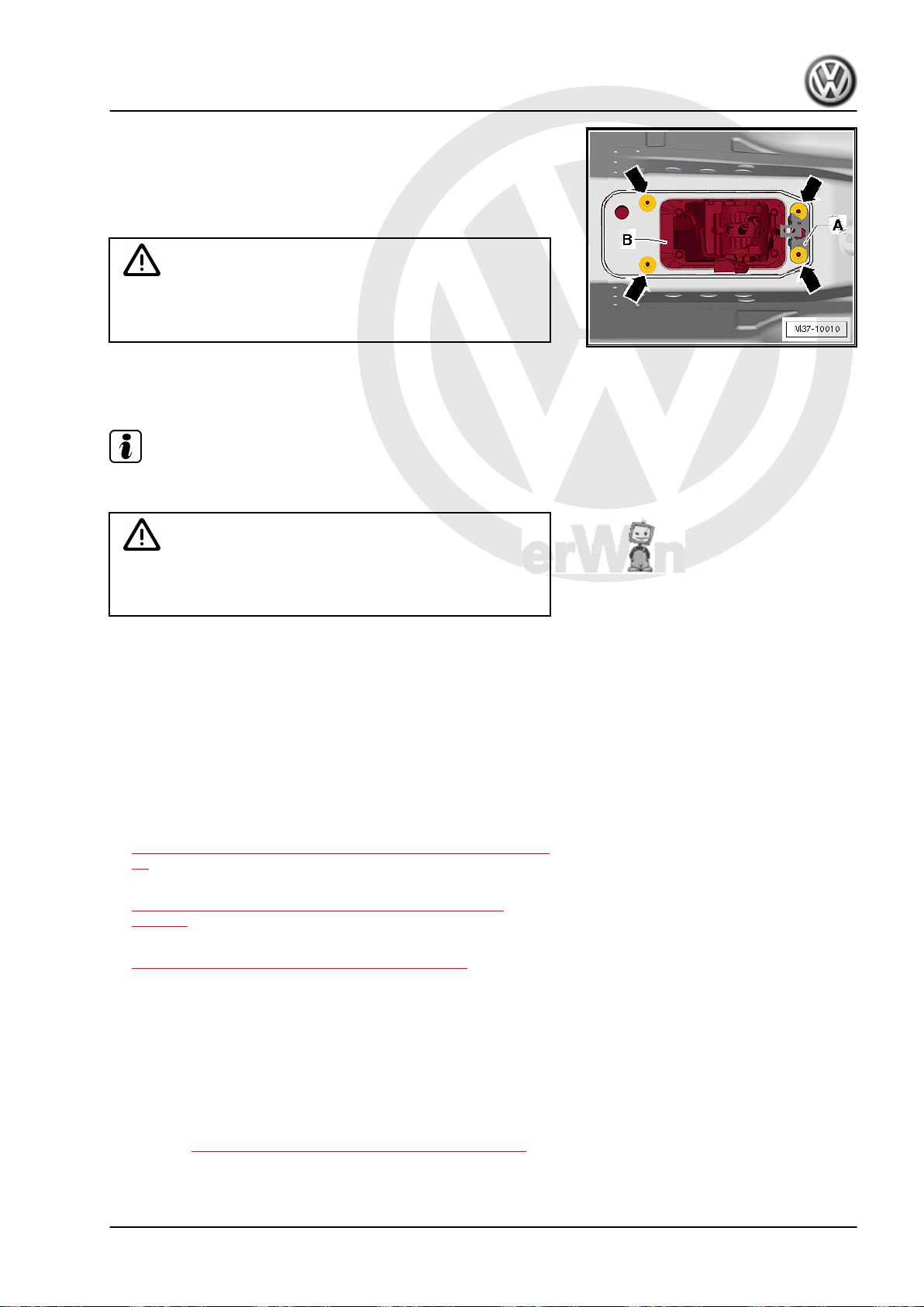
P
r
o
t
e
c
t
e
d
b
y
c
o
p
y
r
i
g
h
t
.
C
o
p
y
i
n
g
f
o
r
p
r
i
v
a
t
e
o
r
c
o
m
m
e
r
c
i
a
l
p
u
r
p
o
s
e
s
,
i
n
p
a
r
t
o
r
i
n
w
h
o
l
e
,
i
s
n
o
t
p
e
r
m
i
t
t
e
d
u
n
l
e
s
s
a
u
t
h
o
r
i
s
e
d
b
y
V
o
l
k
s
w
a
g
e
n
A
G
.
V
o
l
k
s
w
a
g
e
n
A
G
d
o
e
s
n
o
t
g
u
a
r
a
n
t
e
e
o
r
a
c
c
e
p
t
a
n
y
l
i
a
b
i
l
i
t
y
w
i
t
h
r
e
s
p
e
c
t
t
o
t
h
e
c
o
r
r
e
c
t
n
e
s
s
o
f
i
n
f
o
r
m
a
t
i
o
n
i
n
t
h
i
s
d
o
c
u
m
e
n
t
.
C
o
p
y
r
i
g
h
t
b
y
V
o
l
k
s
w
a
g
e
n
A
G
.
– Remove the nuts -arrows- in the vehicle interior.
– Remove the bracket -A-, if equipped.
– Remove the selector mechanism -B- with the selector lever
cable and selector housing downward. Guide the selector lev‐
er cable out of the cable bracket at the same time.
Caution
Danger of damaging the selector lever cable.
♦ Do not bend or kink the selector lever cable.
Installing
Install in reverse order of removal. Note the following:
Note
Do not lubricate the selector lever cable.
Caution
Danger of damaging the selector lever cable.
♦ Do not bend or kink the selector lever cable.
Direct Shift Gearbox - Edition 01.2016
Jetta Hybrid 2013 ➤
– Install the heat shield under the shift mechanism.
– Install the exhaust system and align it free of tension. Refer to
⇒ Engine Mechanical, Fuel Injection and Ignition; Rep. Gr.
26 ; Overview - Emissions Control .
– Attach the front and rear tunnel braces to the body. Refer to
⇒ Body Exterior; Rep. Gr. 50 ; Tunnel Bridge .
– Install the center console. Refer to ⇒ Body Interior; Rep. Gr.
68 ; Center Console; Center Console, Removing and Instal‐
ling .
– Install the selector lever handle. Refer to
⇒ “2.3 Selector Lever Handle, Removing and Installing”, page
74 .
– Adjust the selector lever cable. Refer to
⇒ “2.7 Selector Lever Cable, Checking and Adjusting”,
page 87 .
– Check the selector mechanism. Refer to
⇒ “2.6 Gearshift Mechanism, Checking”, page 86 .
– Install the Electric Drive Power and Control Electronics - JX1- .
Refer to ⇒ Electrical Equipment; Rep. Gr. 93 ; Electric Drive
Power and Control Electronics; Electric Drive Power and Con‐
trol Electronics, Removing and Installing .
– Energize the high voltage system and complete the required
documentation. Refer to ⇒ Electrical System Hybrid; Rep. Gr.
93 ; High Voltage System, Energizing .
Tightening Specifications
♦ Refer to ⇒ “2.1 Overview - Selector Mechanism”, page 71
2. Selector Mechanism 81
Page 86
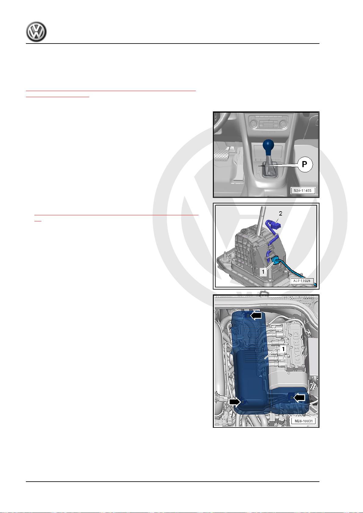
P
r
o
t
e
c
t
e
d
b
y
c
o
p
y
r
i
g
h
t
.
C
o
p
y
i
n
g
f
o
r
p
r
i
v
a
t
e
o
r
c
o
m
m
e
r
c
i
a
l
p
u
r
p
o
s
e
s
,
i
n
p
a
r
t
o
r
i
n
w
h
o
l
e
,
i
s
n
o
t
p
e
r
m
i
t
t
e
d
u
n
l
e
s
s
a
u
t
h
o
r
i
s
e
d
b
y
V
o
l
k
s
w
a
g
e
n
A
G
.
V
o
l
k
s
w
a
g
e
n
A
G
d
o
e
s
n
o
t
g
u
a
r
a
n
t
e
e
o
r
a
c
c
e
p
t
a
n
y
l
i
a
b
i
l
i
t
y
w
i
t
h
r
e
s
p
e
c
t
t
o
t
h
e
c
o
r
r
e
c
t
n
e
s
s
o
f
i
n
f
o
r
m
a
t
i
o
n
i
n
t
h
i
s
d
o
c
u
m
e
n
t
.
C
o
p
y
r
i
g
h
t
b
y
V
o
l
k
s
w
a
g
e
n
A
G
.
Jetta Hybrid 2013 ➤
Direct Shift Gearbox - Edition 01.2016
2.5.2 Selector Mechanism without Selector Housing, Removing and Installing
The selector mechanism with selector lever cable can be re‐
moved and installed together with the selector housing. Refer to
⇒ “2.5.1 Selector Mechanism with Selector Housing, Removing
and Installing”, page 77 .
Removing
– Move the selector lever into “P”.
– Remove the selector lever handle. Refer to
⇒ “2.3 Selector Lever Handle, Removing and Installing”, page
74 . Disconnect the connector -2- from the cover while doing
this.
– Remove the center console. Refer to ⇒ Body Interior; Rep.
Gr. 68 ; Center Console; Center Console, Removing and In‐
stalling .
– Disconnect the connector -1- from the selector mechanism to
the vehicle wiring harness.
– Unclip and remove the damper cover -1- upward from the re‐
tainers -arrows-.
Vehicles with Secondary Air Injection (AIR) System
82 Rep. Gr.34 - Controls, Housing
Page 87
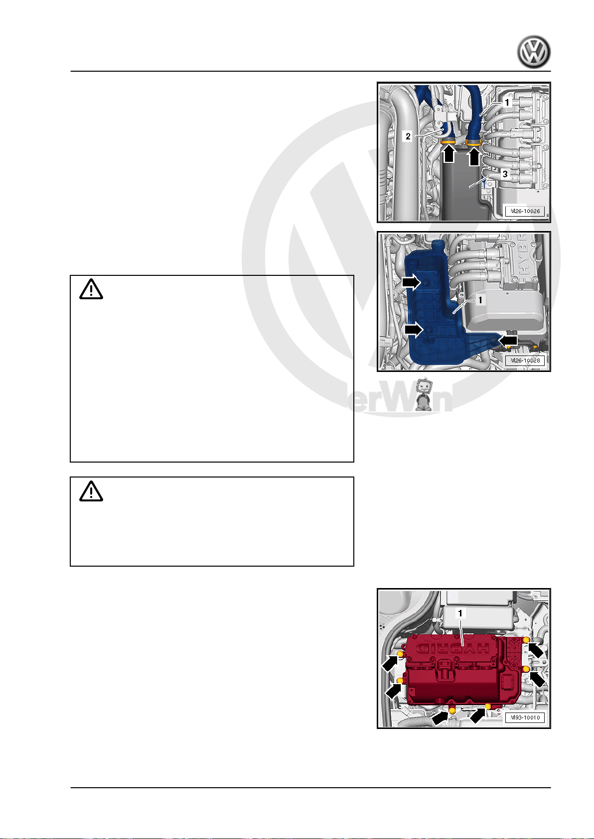
P
r
o
t
e
c
t
e
d
b
y
c
o
p
y
r
i
g
h
t
.
C
o
p
y
i
n
g
f
o
r
p
r
i
v
a
t
e
o
r
c
o
m
m
e
r
c
i
a
l
p
u
r
p
o
s
e
s
,
i
n
p
a
r
t
o
r
i
n
w
h
o
l
e
,
i
s
n
o
t
p
e
r
m
i
t
t
e
d
u
n
l
e
s
s
a
u
t
h
o
r
i
s
e
d
b
y
V
o
l
k
s
w
a
g
e
n
A
G
.
V
o
l
k
s
w
a
g
e
n
A
G
d
o
e
s
n
o
t
g
u
a
r
a
n
t
e
e
o
r
a
c
c
e
p
t
a
n
y
l
i
a
b
i
l
i
t
y
w
i
t
h
r
e
s
p
e
c
t
t
o
t
h
e
c
o
r
r
e
c
t
n
e
s
s
o
f
i
n
f
o
r
m
a
t
i
o
n
i
n
t
h
i
s
d
o
c
u
m
e
n
t
.
C
o
p
y
r
i
g
h
t
b
y
V
o
l
k
s
w
a
g
e
n
A
G
.
Jetta Hybrid 2013 ➤
Direct Shift Gearbox - Edition 01.2016
– Squeeze the locking ring -arrows- on both sides and remove
the air lines -1 and 2- from the damper -3-.
– Remove the damper -1- upward from the rubber bushings
-arrows-.
For All Vehicles
Beware of the danger of electrocution.
An electrical shock can result in death.
Follow the High Voltage System General Warnings. Refer to
⇒ Electrical System Hybrid; Rep. Gr. 93 ; High Voltage System
General Warnings .
♦ A high voltage technician must de-energize the high volt‐
age system before any can work can be performed on the
WARNING
high voltage system or before any servicing work can be
performed on the body.
♦ Only hybrid electrically instructed persons may perform all
work on a vehicle with a high voltage system. All work
must be performed by a high voltage technician.
WARNING
High voltage at the high voltage system of the hybrid vehicle.
Danger of electrocution! The following procedure requires
work on the high voltage system. To de-energize the high volt‐
age system. Refer to ⇒ Hybrid Electrical System; Rep. Gr.
93 ; High Voltage System, De-energizing .
– Remove the Electric Drive Power and Control Electronics -
JX1- . Refer to ⇒ Electrical Equipment; Rep. Gr. 93 ; Electric
Drive Power and Control Electronics; Electric Drive Power and
Control Electronics, Removing and Installing .
2. Selector Mechanism 83
Page 88
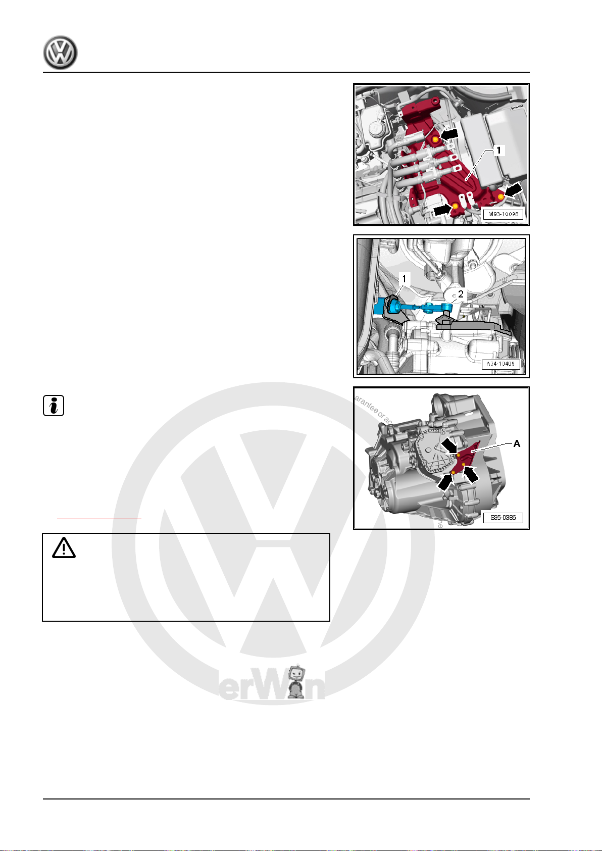
P
r
o
t
e
c
t
e
d
b
y
c
o
p
y
r
i
g
h
t
.
C
o
p
y
i
n
g
f
o
r
p
r
i
v
a
t
e
o
r
c
o
m
m
e
r
c
i
a
l
p
u
r
p
o
s
e
s
,
i
n
p
a
r
t
o
r
i
n
w
h
o
l
e
,
i
s
n
o
t
p
e
r
m
i
t
t
e
d
u
n
l
e
s
s
a
u
t
h
o
r
i
s
e
d
b
y
V
o
l
k
s
w
a
g
e
n
A
G
.
V
o
l
k
s
w
a
g
e
n
A
G
d
o
e
s
n
o
t
g
u
a
r
a
n
t
e
e
o
r
a
c
c
e
p
t
a
n
y
l
i
a
b
i
l
i
t
y
w
i
t
h
r
e
s
p
e
c
t
t
o
t
h
e
c
o
r
r
e
c
t
n
e
s
s
o
f
i
n
f
o
r
m
a
t
i
o
n
i
n
t
h
i
s
d
o
c
u
m
e
n
t
.
C
o
p
y
r
i
g
h
t
b
y
V
o
l
k
s
w
a
g
e
n
A
G
.
Jetta Hybrid 2013 ➤
Direct Shift Gearbox - Edition 01.2016
– Remove the bracket -1- for the Electric Drive Power And Con‐
trol Electronics - JX1- -arrows-. Refer to ⇒ Electrical System
Hybrid; Rep. Gr. 93 ; High Voltage Cables; High Voltage Bat‐
tery High Voltage Cable Set, Removing and Installing .
– Remove the lock washer -1- from the selector lever cable.
Always replace the circlip on the selector lever cable.
– Remove the selector lever cable -2- from the lever/gearshift
shaft, for example, with Pry Lever - 80-200- .
Note
♦
Use pliers to remove the lock washer -1-. Do not use a sharpedged lever. Otherwise the selector lever cable could get
damaged.
♦
Remove the cable bracket -A- and selector lever cable from
the transmission, if necessary. To do this, remove the bolts
-arrows-. These bolts must be replaced.
♦
Bolt tightening specification -arrows- -item 7-
⇒ Item 7 (page 73) .
Danger of damaging the selector lever cable.
♦ Push the selector lever cable to the rear and out of the
cable bracket. Guide the selector lever cable out of the
Caution
cable bracket when removing the selector mechanism.
– Attach a longer cord to the end of the cable. The cord is used
to guide the cable between the tunnel and the heat shield dur‐
ing installation.
84 Rep. Gr.34 - Controls, Housing
Page 89
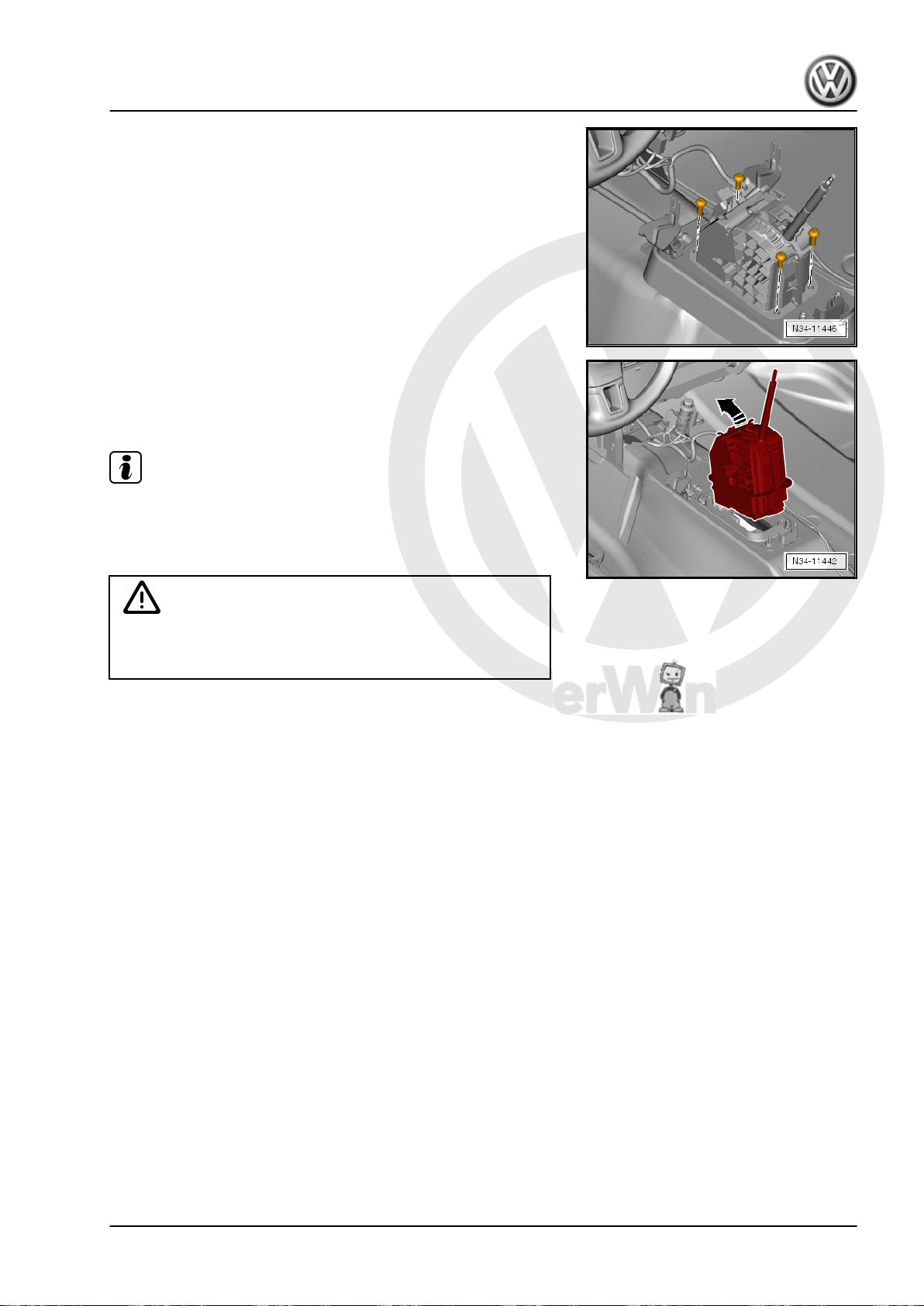
P
r
o
t
e
c
t
e
d
b
y
c
o
p
y
r
i
g
h
t
.
C
o
p
y
i
n
g
f
o
r
p
r
i
v
a
t
e
o
r
c
o
m
m
e
r
c
i
a
l
p
u
r
p
o
s
e
s
,
i
n
p
a
r
t
o
r
i
n
w
h
o
l
e
,
i
s
n
o
t
p
e
r
m
i
t
t
e
d
u
n
l
e
s
s
a
u
t
h
o
r
i
s
e
d
b
y
V
o
l
k
s
w
a
g
e
n
A
G
.
V
o
l
k
s
w
a
g
e
n
A
G
d
o
e
s
n
o
t
g
u
a
r
a
n
t
e
e
o
r
a
c
c
e
p
t
a
n
y
l
i
a
b
i
l
i
t
y
w
i
t
h
r
e
s
p
e
c
t
t
o
t
h
e
c
o
r
r
e
c
t
n
e
s
s
o
f
i
n
f
o
r
m
a
t
i
o
n
i
n
t
h
i
s
d
o
c
u
m
e
n
t
.
C
o
p
y
r
i
g
h
t
b
y
V
o
l
k
s
w
a
g
e
n
A
G
.
Direct Shift Gearbox - Edition 01.2016
– Remove the 4 bolts attaching the selector mechanism to the
selector housing.
– Pull the selector mechanism and cable out of the center tunnel
in direction of -arrow-. Make sure the cord is pull through far
enough so that it can reached from inside the engine com‐
partment.
– Remove the cord from the cable.
Installing
Install in reverse order of removal. Note the following:
Note
♦
A second technician will be needed for inserting the cable from
the passenger compartment into the engine compartment.
♦
Do not lubricate the selector lever cable.
Danger of damaging the selector lever cable.
♦ Do not bend or kink the selector lever cable.
Caution
– Secure the cord to the end of the cable.
– Guide the selector mechanism and cable through the opening
in the center tunnel.
Jetta Hybrid 2013 ➤
– From the engine compartment, the second technician pulls the
cord with the cable through the tunnel until it is possible to
attach the cable to the support bracket.
– Remove the cord from the cable.
2. Selector Mechanism 85
Page 90
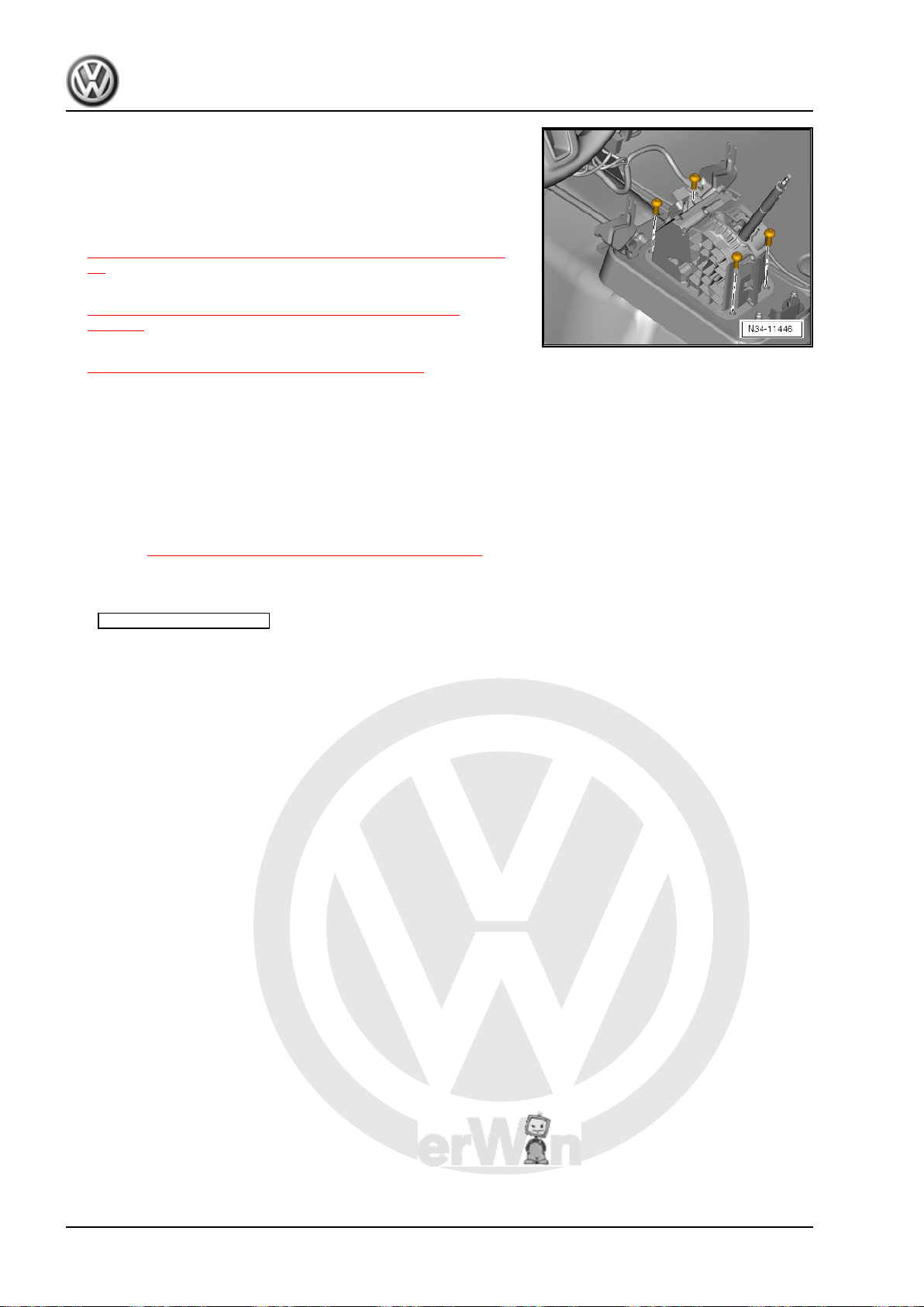
P
r
o
t
e
c
t
e
d
b
y
c
o
p
y
r
i
g
h
t
.
C
o
p
y
i
n
g
f
o
r
p
r
i
v
a
t
e
o
r
c
o
m
m
e
r
c
i
a
l
p
u
r
p
o
s
e
s
,
i
n
p
a
r
t
o
r
i
n
w
h
o
l
e
,
i
s
n
o
t
p
e
r
m
i
t
t
e
d
u
n
l
e
s
s
a
u
t
h
o
r
i
s
e
d
b
y
V
o
l
k
s
w
a
g
e
n
A
G
.
V
o
l
k
s
w
a
g
e
n
A
G
d
o
e
s
n
o
t
g
u
a
r
a
n
t
e
e
o
r
a
c
c
e
p
t
a
n
y
l
i
a
b
i
l
i
t
y
w
i
t
h
r
e
s
p
e
c
t
t
o
t
h
e
c
o
r
r
e
c
t
n
e
s
s
o
f
i
n
f
o
r
m
a
t
i
o
n
i
n
t
h
i
s
d
o
c
u
m
e
n
t
.
C
o
p
y
r
i
g
h
t
b
y
V
o
l
k
s
w
a
g
e
n
A
G
.
Jetta Hybrid 2013 ➤
Direct Shift Gearbox - Edition 01.2016
– Attach the selector mechanism to the selector housing with
four bolts.
– Install the center console. Refer to ⇒ Body Interior; Rep. Gr.
68 ; Center Console; Center Console, Removing and Instal‐
ling .
– Install the selector lever handle. Refer to
⇒ “2.3 Selector Lever Handle, Removing and Installing”, page
74 .
– Adjust the selector lever cable. Refer to
⇒ “2.7 Selector Lever Cable, Checking and Adjusting”,
page 87 .
– Check the selector mechanism. Refer to
⇒ “2.6 Gearshift Mechanism, Checking”, page 86 .
– Install the Electric Drive Power and Control Electronics - JX1- .
Refer to ⇒ Electrical Equipment; Rep. Gr. 93 ; Electric Drive
Power and Control Electronics; Electric Drive Power and Con‐
trol Electronics, Removing and Installing .
– Energize the high voltage system and complete the required
documentation. Refer to ⇒ Electrical System Hybrid; Rep. Gr.
93 ; High Voltage System, Energizing .
Tightening Specifications
♦ Refer to ⇒ “2.1 Overview - Selector Mechanism”, page 71
2.6 Gearshift Mechanism, Checking
Use Guided Fault Finding to determine electric faults. A me‐
chanical fault or a faulty system or a faulty part must be found and
repaired.
It is not possible to start the engine when the selector lever is in
“R”, “D” and “S” or in the tiptronic position.
If selector lever position “N” is selected at speeds greater than 5
km/h, the shift lock solenoid must not engage and block the se‐
lector lever. The selector lever can be moved into a another gear.
The shift lock solenoid must engage after approximately 1 second
only at speeds below 5 km/h (almost standstill) and when the se‐
lector lever is moved into “N”. The selector lever can be moved
out of “N” only when the brake pedal is pressed.
Selector Lever in “P” and the Ignition Turned On:
• If the brake pedal is not depressed:
The selector lever is locked and cannot be moved out of “P” when
the locking button is pressed. The shift lock solenoid blocks the
selector lever.
• If the brake pedal is depressed:
The shift lock solenoid releases the selector lever. It is possible
to shift into a gear. Slowly move the selector lever slowly from “P”
through “S”; while doing this, check whether display of selector
lever position in instrument panel insert matches actual selector
lever position.
The Selector Lever is in “N” and the Ignition Is Turned On
• If the brake pedal is not depressed:
The selector lever is locked and cannot be moved out of “N” when
the button is pressed. The shift lock solenoid blocks the selector
lever.
• If the brake pedal is depressed:
86 Rep. Gr.34 - Controls, Housing
Page 91
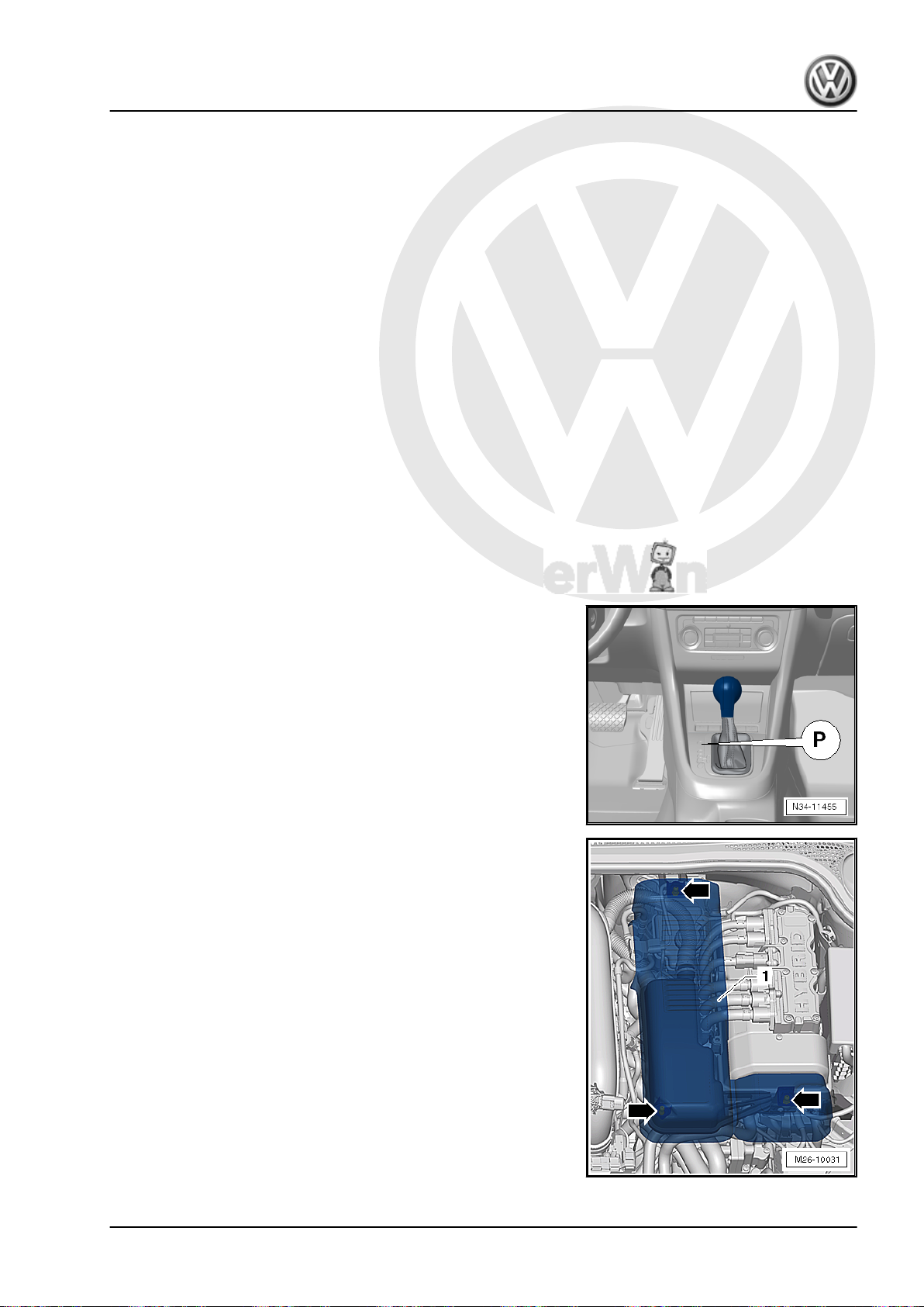
P
r
o
t
e
c
t
e
d
b
y
c
o
p
y
r
i
g
h
t
.
C
o
p
y
i
n
g
f
o
r
p
r
i
v
a
t
e
o
r
c
o
m
m
e
r
c
i
a
l
p
u
r
p
o
s
e
s
,
i
n
p
a
r
t
o
r
i
n
w
h
o
l
e
,
i
s
n
o
t
p
e
r
m
i
t
t
e
d
u
n
l
e
s
s
a
u
t
h
o
r
i
s
e
d
b
y
V
o
l
k
s
w
a
g
e
n
A
G
.
V
o
l
k
s
w
a
g
e
n
A
G
d
o
e
s
n
o
t
g
u
a
r
a
n
t
e
e
o
r
a
c
c
e
p
t
a
n
y
l
i
a
b
i
l
i
t
y
w
i
t
h
r
e
s
p
e
c
t
t
o
t
h
e
c
o
r
r
e
c
t
n
e
s
s
o
f
i
n
f
o
r
m
a
t
i
o
n
i
n
t
h
i
s
d
o
c
u
m
e
n
t
.
C
o
p
y
r
i
g
h
t
b
y
V
o
l
k
s
w
a
g
e
n
A
G
.
The shift lock solenoid releases the selector lever. It is possible
to shift into a gear.
Selector Level in the “tiptronic” Position
– Move the selector lever into the tiptronic gate.
“P R N D S” must change to “7 6 5 4 3 2 1”.
The Ignition and Lights Must Be Turned On
The appropriate symbol is being lit up in shift mechanism cover.
Transmission Range Display
Simultaneous lighting of all segments of transmission range se‐
lector lever display indicates transmission is in emergency run‐
ning mode.
2.7 Selector Lever Cable, Checking and Ad‐
Selector lever cable must be adjusted if:
justing
♦ The selector lever cable was removed from the transmission.
♦ The engine and transmission were removed and installed.
♦ The selector lever cable and the selector mechanism were re‐
moved and installed.
♦ Engine/transmission positions changes, for example, were in‐
stalled free of tension.
Direct Shift Gearbox - Edition 01.2016
– Move the selector lever into “P”.
Jetta Hybrid 2013 ➤
– Unclip and remove the damper cover -1- upward from the re‐
tainers -arrows-.
Vehicles with Secondary Air Injection (AIR) System
2. Selector Mechanism 87
Page 92
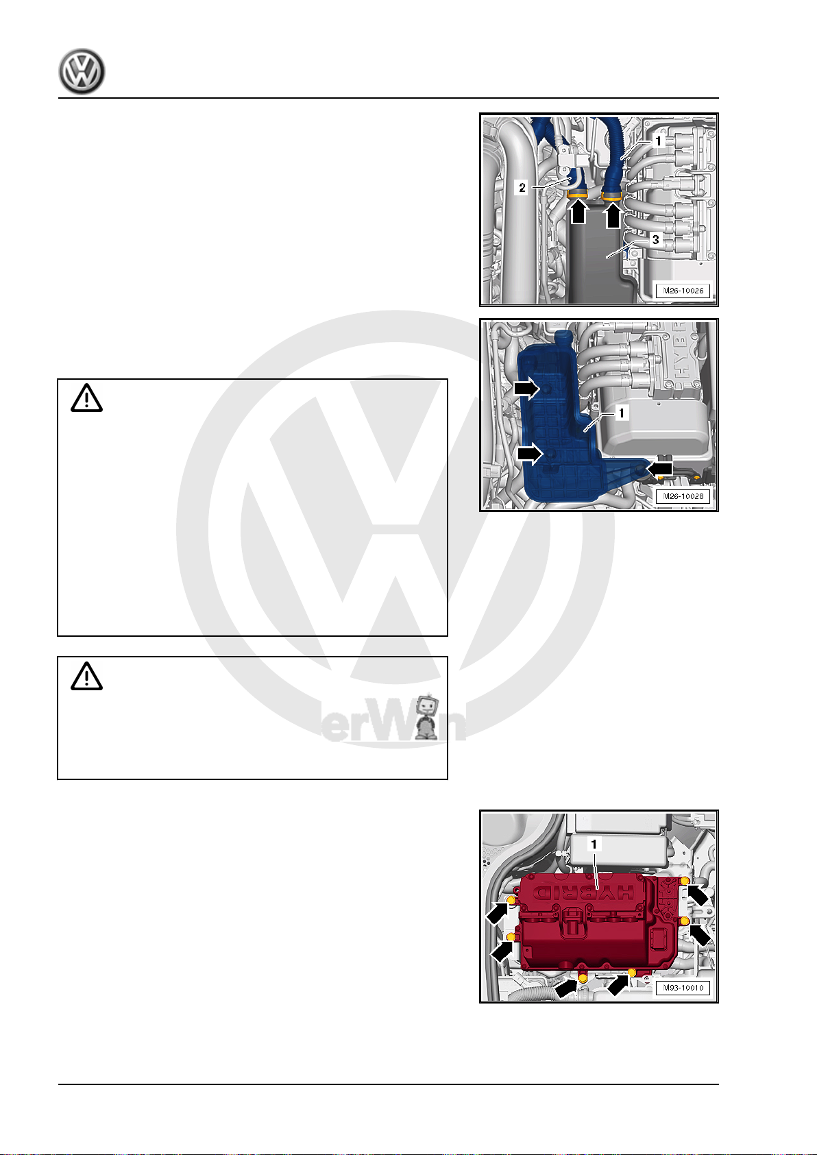
P
r
o
t
e
c
t
e
d
b
y
c
o
p
y
r
i
g
h
t
.
C
o
p
y
i
n
g
f
o
r
p
r
i
v
a
t
e
o
r
c
o
m
m
e
r
c
i
a
l
p
u
r
p
o
s
e
s
,
i
n
p
a
r
t
o
r
i
n
w
h
o
l
e
,
i
s
n
o
t
p
e
r
m
i
t
t
e
d
u
n
l
e
s
s
a
u
t
h
o
r
i
s
e
d
b
y
V
o
l
k
s
w
a
g
e
n
A
G
.
V
o
l
k
s
w
a
g
e
n
A
G
d
o
e
s
n
o
t
g
u
a
r
a
n
t
e
e
o
r
a
c
c
e
p
t
a
n
y
l
i
a
b
i
l
i
t
y
w
i
t
h
r
e
s
p
e
c
t
t
o
t
h
e
c
o
r
r
e
c
t
n
e
s
s
o
f
i
n
f
o
r
m
a
t
i
o
n
i
n
t
h
i
s
d
o
c
u
m
e
n
t
.
C
o
p
y
r
i
g
h
t
b
y
V
o
l
k
s
w
a
g
e
n
A
G
.
Jetta Hybrid 2013 ➤
Direct Shift Gearbox - Edition 01.2016
– Squeeze the locking ring -arrows- on both sides and remove
the air lines -1 and 2- from the damper -3-.
– Remove the damper -1- upward from the rubber bushings
-arrows-.
For All Vehicles
WARNING
Beware of the danger of electrocution.
An electrical shock can result in death.
Follow the High Voltage System General Warnings. Refer to
⇒ Electrical System Hybrid; Rep. Gr. 93 ; High Voltage System
General Warnings .
♦ A high voltage technician must de-energize the high volt‐
age system before any can work can be performed on the
high voltage system or before any servicing work can be
performed on the body.
♦ Only hybrid electrically instructed persons may perform all
work on a vehicle with a high voltage system. All work
must be performed by a high voltage technician.
WARNING
High voltage at the high voltage system of the hybrid vehicle.
Danger of electrocution! The following procedure requires
work on the high voltage system. To de-energize the high volt‐
age system. Refer to ⇒ Hybrid Electrical System; Rep. Gr.
93 ; High Voltage System, De-energizing .
– Remove the Electric Drive Power and Control Electronics -
JX1- . Refer to ⇒ Electrical Equipment; Rep. Gr. 93 ; Electric
Drive Power and Control Electronics; Electric Drive Power and
Control Electronics, Removing and Installing .
88 Rep. Gr.34 - Controls, Housing
Page 93
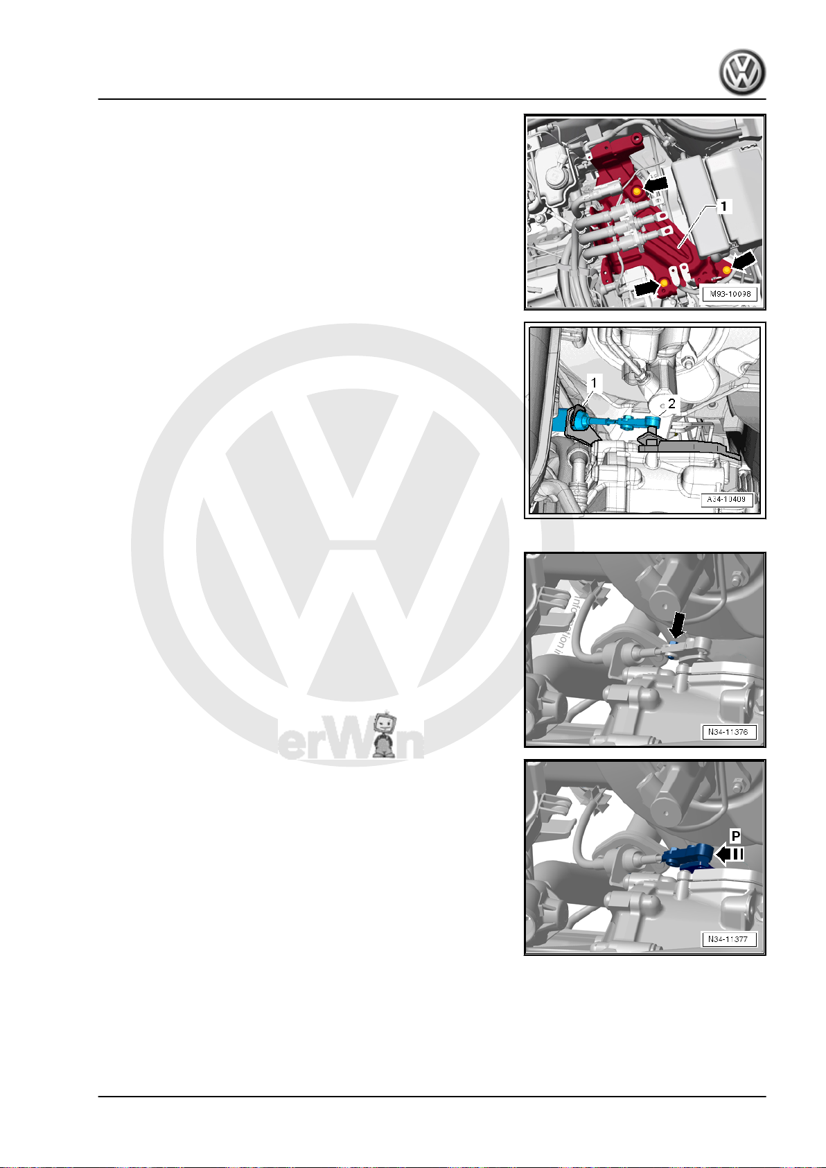
P
r
o
t
e
c
t
e
d
b
y
c
o
p
y
r
i
g
h
t
.
C
o
p
y
i
n
g
f
o
r
p
r
i
v
a
t
e
o
r
c
o
m
m
e
r
c
i
a
l
p
u
r
p
o
s
e
s
,
i
n
p
a
r
t
o
r
i
n
w
h
o
l
e
,
i
s
n
o
t
p
e
r
m
i
t
t
e
d
u
n
l
e
s
s
a
u
t
h
o
r
i
s
e
d
b
y
V
o
l
k
s
w
a
g
e
n
A
G
.
V
o
l
k
s
w
a
g
e
n
A
G
d
o
e
s
n
o
t
g
u
a
r
a
n
t
e
e
o
r
a
c
c
e
p
t
a
n
y
l
i
a
b
i
l
i
t
y
w
i
t
h
r
e
s
p
e
c
t
t
o
t
h
e
c
o
r
r
e
c
t
n
e
s
s
o
f
i
n
f
o
r
m
a
t
i
o
n
i
n
t
h
i
s
d
o
c
u
m
e
n
t
.
C
o
p
y
r
i
g
h
t
b
y
V
o
l
k
s
w
a
g
e
n
A
G
.
Direct Shift Gearbox - Edition 01.2016
– Remove the bracket -1- for the Electric Drive Power And Con‐
trol Electronics - JX1- -arrows-. Refer to ⇒ Electrical System
Hybrid; Rep. Gr. 93 ; High Voltage Cables; High Voltage Bat‐
tery High Voltage Cable Set, Removing and Installing .
Selector Lever Cable, Checking
– Remove the selector lever cable -2- from the transmission se‐
lector lever using Pry Lever - 80-200- .
– Remove the lock washer -1- from the selector lever cable, if
necessary.
Always replace the circlip on the selector lever cable.
– Move the selector lever from »P« through »S« and back to »P«
several times.
• Selector mechanism and selector lever cable move easily
• The selector lever cable is undamaged.
Selector Lever Cable, Adjusting
– Loosen the adjusting screw -arrow- on the selector lever cable.
– Shift the transmission gearshift lever into “P”.
when shifting.
The selector lever must pushed all the way toward the right side
of the vehicle, in the direction toward the selector lever cable
bracket.
Jetta Hybrid 2013 ➤
2. Selector Mechanism 89
Page 94
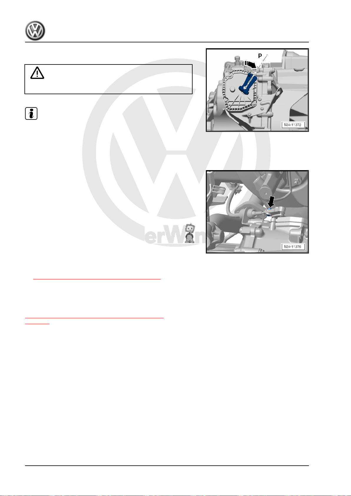
P
r
o
t
e
c
t
e
d
b
y
c
o
p
y
r
i
g
h
t
.
C
o
p
y
i
n
g
f
o
r
p
r
i
v
a
t
e
o
r
c
o
m
m
e
r
c
i
a
l
p
u
r
p
o
s
e
s
,
i
n
p
a
r
t
o
r
i
n
w
h
o
l
e
,
i
s
n
o
t
p
e
r
m
i
t
t
e
d
u
n
l
e
s
s
a
u
t
h
o
r
i
s
e
d
b
y
V
o
l
k
s
w
a
g
e
n
A
G
.
V
o
l
k
s
w
a
g
e
n
A
G
d
o
e
s
n
o
t
g
u
a
r
a
n
t
e
e
o
r
a
c
c
e
p
t
a
n
y
l
i
a
b
i
l
i
t
y
w
i
t
h
r
e
s
p
e
c
t
t
o
t
h
e
c
o
r
r
e
c
t
n
e
s
s
o
f
i
n
f
o
r
m
a
t
i
o
n
i
n
t
h
i
s
d
o
c
u
m
e
n
t
.
C
o
p
y
r
i
g
h
t
b
y
V
o
l
k
s
w
a
g
e
n
A
G
.
Jetta Hybrid 2013 ➤
Direct Shift Gearbox - Edition 01.2016
The illustration shows the transmission from the rear. -P- is toward
the cable bracket.
WARNING
The parking lock must be engaged.
Note
Make sure the transmission is in “P” (parking lock is engaged) if
raising the vehicle. It must not be possible to turn the front wheels.
– To release selector lever cable tension, carefully move selec‐
tor lever front and back slightly but do not shift into another
selector lever position.
– Tighten the adjusting screw -arrow-. The position of the se‐
lector lever cable must not change while doing this.
This ends the adjustment.
– The rest of the installation is performed in reverse order of re‐
moval. When doing this, install the Electric Drive Power and
Control Electronics - JX1- . Refer to ⇒ Electrical System Hy‐
brid; Rep. Gr. 93 ; Electric Drive Power and Control Electron‐
ics; Electric Drive Power and Control Electronics, Removing
and Installing .
– Energize the high voltage system and complete the required
documentation. Refer to ⇒ Electrical System Hybrid; Rep. Gr.
93 ; High Voltage System, Energizing .
Tightening Specifications
♦ Selector lever cable adjusting screw. Refer to
⇒ “2.1 Overview - Selector Mechanism”, page 71
2.8 Selector Shaft Seal, Replacing
The selector shaft seal can currently be replaced only together
with the parking lock cover. Refer to
⇒ “1.1 Parking Lock Cover, Removing and Installing”,
page 121 .
90 Rep. Gr.34 - Controls, Housing
Page 95
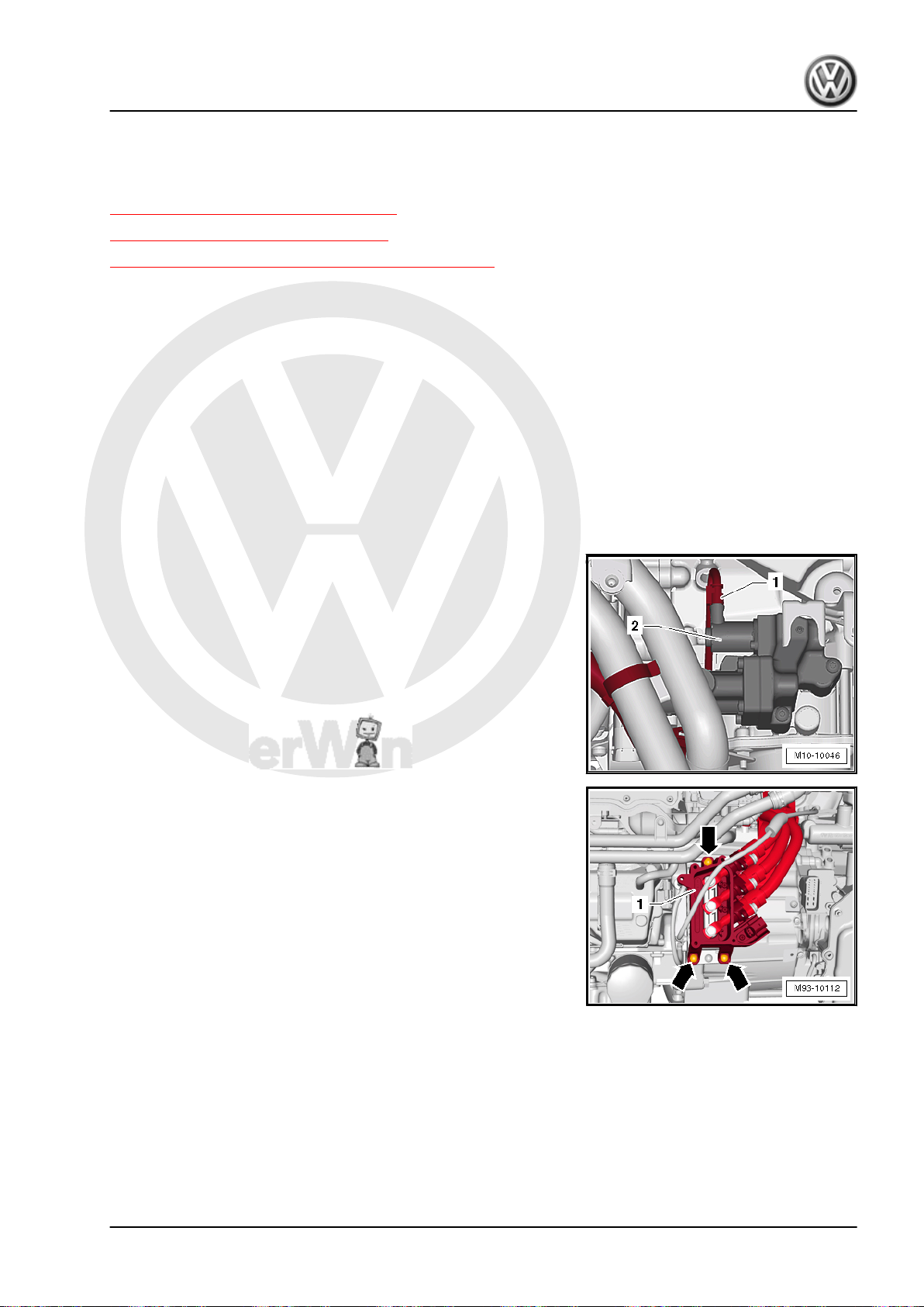
P
r
o
t
e
c
t
e
d
b
y
c
o
p
y
r
i
g
h
t
.
C
o
p
y
i
n
g
f
o
r
p
r
i
v
a
t
e
o
r
c
o
m
m
e
r
c
i
a
l
p
u
r
p
o
s
e
s
,
i
n
p
a
r
t
o
r
i
n
w
h
o
l
e
,
i
s
n
o
t
p
e
r
m
i
t
t
e
d
u
n
l
e
s
s
a
u
t
h
o
r
i
s
e
d
b
y
V
o
l
k
s
w
a
g
e
n
A
G
.
V
o
l
k
s
w
a
g
e
n
A
G
d
o
e
s
n
o
t
g
u
a
r
a
n
t
e
e
o
r
a
c
c
e
p
t
a
n
y
l
i
a
b
i
l
i
t
y
w
i
t
h
r
e
s
p
e
c
t
t
o
t
h
e
c
o
r
r
e
c
t
n
e
s
s
o
f
i
n
f
o
r
m
a
t
i
o
n
i
n
t
h
i
s
d
o
c
u
m
e
n
t
.
C
o
p
y
r
i
g
h
t
b
y
V
o
l
k
s
w
a
g
e
n
A
G
.
3 Transmission, Removing and Instal‐
ling
⇒ “3.1 Transmission, Removing”, page 91
⇒ “3.2 Transmission, Installing”, page 95
⇒ “3.3 Transmission Tightening Specifications”, page 99
3.1 Transmission, Removing
– The transmission and engine are removed. Refer to ⇒ Rep.
Gr. 10 ; Engine, Removing and Installing; Engine, Removing .
Removing Transmission from Engine
Special tools and workshop equipment required
♦ Bits for VAG1331/13 - T10099-
♦ Socket - Xzn 14 - T10061-
♦ Engine/Gearbox Support Shackle (2 pc.) - 10-222A/12-
♦ Shop Crane - VAS6100-
• The engine/transmission sub-assembly is removed with the
Scissor Lift Table - VAS6131- .
– Disconnect the connector -1- from the valve -2- on the Me‐
chatronic and pull the wiring harness from the front bracket on
the transmission.
– Remove the Drive Motor High Voltage Wiring Harness - PX2-
from the transmission together with the connection box. Refer
to -1- -arrows-. Refer to ⇒ Electrical System Hybrid; Rep. Gr.
93 ; High Voltage Cables; Drive Motor High Voltage Wiring
Harness, Removing and Installing .
Jetta Hybrid 2013 ➤
Direct Shift Gearbox - Edition 01.2016
3. Transmission, Removing and Installing 91
Page 96
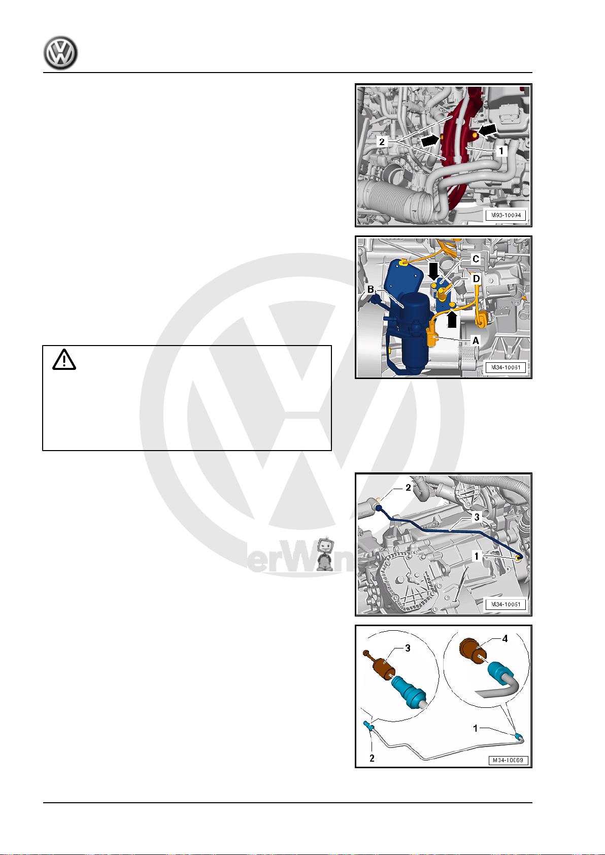
P
r
o
t
e
c
t
e
d
b
y
c
o
p
y
r
i
g
h
t
.
C
o
p
y
i
n
g
f
o
r
p
r
i
v
a
t
e
o
r
c
o
m
m
e
r
c
i
a
l
p
u
r
p
o
s
e
s
,
i
n
p
a
r
t
o
r
i
n
w
h
o
l
e
,
i
s
n
o
t
p
e
r
m
i
t
t
e
d
u
n
l
e
s
s
a
u
t
h
o
r
i
s
e
d
b
y
V
o
l
k
s
w
a
g
e
n
A
G
.
V
o
l
k
s
w
a
g
e
n
A
G
d
o
e
s
n
o
t
g
u
a
r
a
n
t
e
e
o
r
a
c
c
e
p
t
a
n
y
l
i
a
b
i
l
i
t
y
w
i
t
h
r
e
s
p
e
c
t
t
o
t
h
e
c
o
r
r
e
c
t
n
e
s
s
o
f
i
n
f
o
r
m
a
t
i
o
n
i
n
t
h
i
s
d
o
c
u
m
e
n
t
.
C
o
p
y
r
i
g
h
t
b
y
V
o
l
k
s
w
a
g
e
n
A
G
.
Jetta Hybrid 2013 ➤
Direct Shift Gearbox - Edition 01.2016
– Remove the cable bracket -1- for the Drive Motor High Voltage
Wiring Harness - PX2- from the transmission -arrows-. Refer
to ⇒ Electrical System Hybrid; Rep. Gr. 93 ; High Voltage
Cables; Drive Motor High Voltage Wiring Harness, Removing
and Installing .
– Unlock and disconnect the connector -A- from the Brake Sys‐
tem Vacuum Pump - V192- -B-.
– Remove the bracket and Brake System Vacuum Pump - V192-
-B- from the transmission and tie it up on the engine.
– Unlock and disconnect the connector -D- from Drive Motor
Rotor Position Sensor 1 - G713- -C-.
– Remove the bolts -arrows- and Drive Motor Rotor Position
Sensor 1 - G713- .
WARNING
Danger of dirt.
Always clean the connection locations and the area around
them before loosening.
The Mechatronic hydraulic system is not open. Dirt can cause
the system to malfunction.
– Remove the bolt -1- for the hydraulic line -3- on the engine.
– Remove the clamps -2- from the valve block/Mechatronic.
– Remove the hydraulic line -3- on the engine and valve block/
Mechatronic at the same time.
92 Rep. Gr.34 - Controls, Housing
Page 97
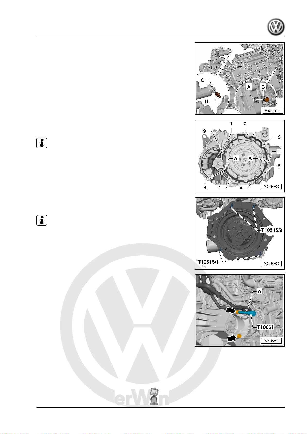
P
r
o
t
e
c
t
e
d
b
y
c
o
p
y
r
i
g
h
t
.
C
o
p
y
i
n
g
f
o
r
p
r
i
v
a
t
e
o
r
c
o
m
m
e
r
c
i
a
l
p
u
r
p
o
s
e
s
,
i
n
p
a
r
t
o
r
i
n
w
h
o
l
e
,
i
s
n
o
t
p
e
r
m
i
t
t
e
d
u
n
l
e
s
s
a
u
t
h
o
r
i
s
e
d
b
y
V
o
l
k
s
w
a
g
e
n
A
G
.
V
o
l
k
s
w
a
g
e
n
A
G
d
o
e
s
n
o
t
g
u
a
r
a
n
t
e
e
o
r
a
c
c
e
p
t
a
n
y
l
i
a
b
i
l
i
t
y
w
i
t
h
r
e
s
p
e
c
t
t
o
t
h
e
c
o
r
r
e
c
t
n
e
s
s
o
f
i
n
f
o
r
m
a
t
i
o
n
i
n
t
h
i
s
d
o
c
u
m
e
n
t
.
C
o
p
y
r
i
g
h
t
b
y
V
o
l
k
s
w
a
g
e
n
A
G
.
Direct Shift Gearbox - Edition 01.2016
• Seal the hydraulic line connections -1 and 2- immediately with
new sealing plugs -3 and 4- from the Repair Kit - 5C0 998
152- . Preferably the hydraulic fluid should remain in the line
if possible, otherwise it should not become dirty.
• Seal the connections on the engine -A- and the valve block/
Mechatronic -C- with new sealing plugs -B and D- from the
Repair Kit - 5C0 998 152- .
• Always use new plugs from the Repair Kit - 5C0 998 152- .
Refer to the Parts Catalog. The sealing plugs cannot be used
again.
– Remove the bolts attaching the transmission to the engine
-1 through 7-.
Note
♦
Loosen the bolts -3 and 4- with the Bit for VAG1331/13 T10099/1- .
♦
Bolts -8 and 9- remain installed.
Jetta Hybrid 2013 ➤
– Install the Centering Mandrel - T10515- into the engine, as
illustrated.
Note
The transmission is not shown in the illustration.
– Remove the engine/transmission connecting bolts -arrows-
from the engine side. Use Socket - Xzn 14 - T10061- . Watch
out for the coolant line -A- while removing the bolts.
– Separate the transmission from the alignment sleeves on the
engine.
3. Transmission, Removing and Installing 93
Page 98
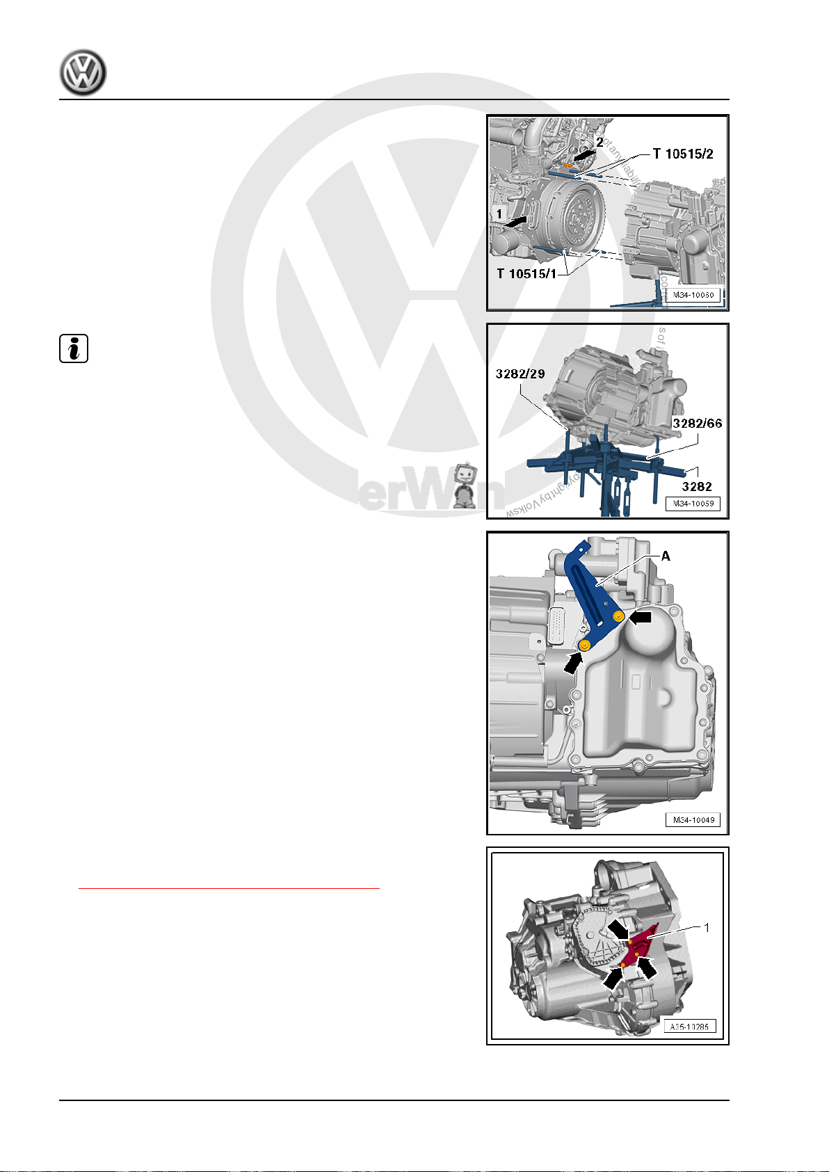
P
r
o
t
e
c
t
e
d
b
y
c
o
p
y
r
i
g
h
t
.
C
o
p
y
i
n
g
f
o
r
p
r
i
v
a
t
e
o
r
c
o
m
m
e
r
c
i
a
l
p
u
r
p
o
s
e
s
,
i
n
p
a
r
t
o
r
i
n
w
h
o
l
e
,
i
s
n
o
t
p
e
r
m
i
t
t
e
d
u
n
l
e
s
s
a
u
t
h
o
r
i
s
e
d
b
y
V
o
l
k
s
w
a
g
e
n
A
G
.
V
o
l
k
s
w
a
g
e
n
A
G
d
o
e
s
n
o
t
g
u
a
r
a
n
t
e
e
o
r
a
c
c
e
p
t
a
n
y
l
i
a
b
i
l
i
t
y
w
i
t
h
r
e
s
p
e
c
t
t
o
t
h
e
c
o
r
r
e
c
t
n
e
s
s
o
f
i
n
f
o
r
m
a
t
i
o
n
i
n
t
h
i
s
d
o
c
u
m
e
n
t
.
C
o
p
y
r
i
g
h
t
b
y
V
o
l
k
s
w
a
g
e
n
A
G
.
Jetta Hybrid 2013 ➤
Direct Shift Gearbox - Edition 01.2016
– Carefully pull the transmission off the engine. Be careful not
to damage the connections -arrow 1- on the Electro-Drive
Drive Motor - V141- and the Drive Motor Temperature Sensor
- G712- -arrow 2-.
Note
It may be necessary to adjust the position of the transmission
while removing it by turning the spindles on the Transmission
Support - 3282- .
If the Transmission Is Going to be Shipped Somewhere
– Remove the front bracket -A- from the transmission -arrows-.
– Remove the cable bracket -1- from the transmission
-arrows-, tightening specification. Refer to
⇒ “2.1 Overview - Selector Mechanism”, page 71 .
94 Rep. Gr.34 - Controls, Housing
Page 99
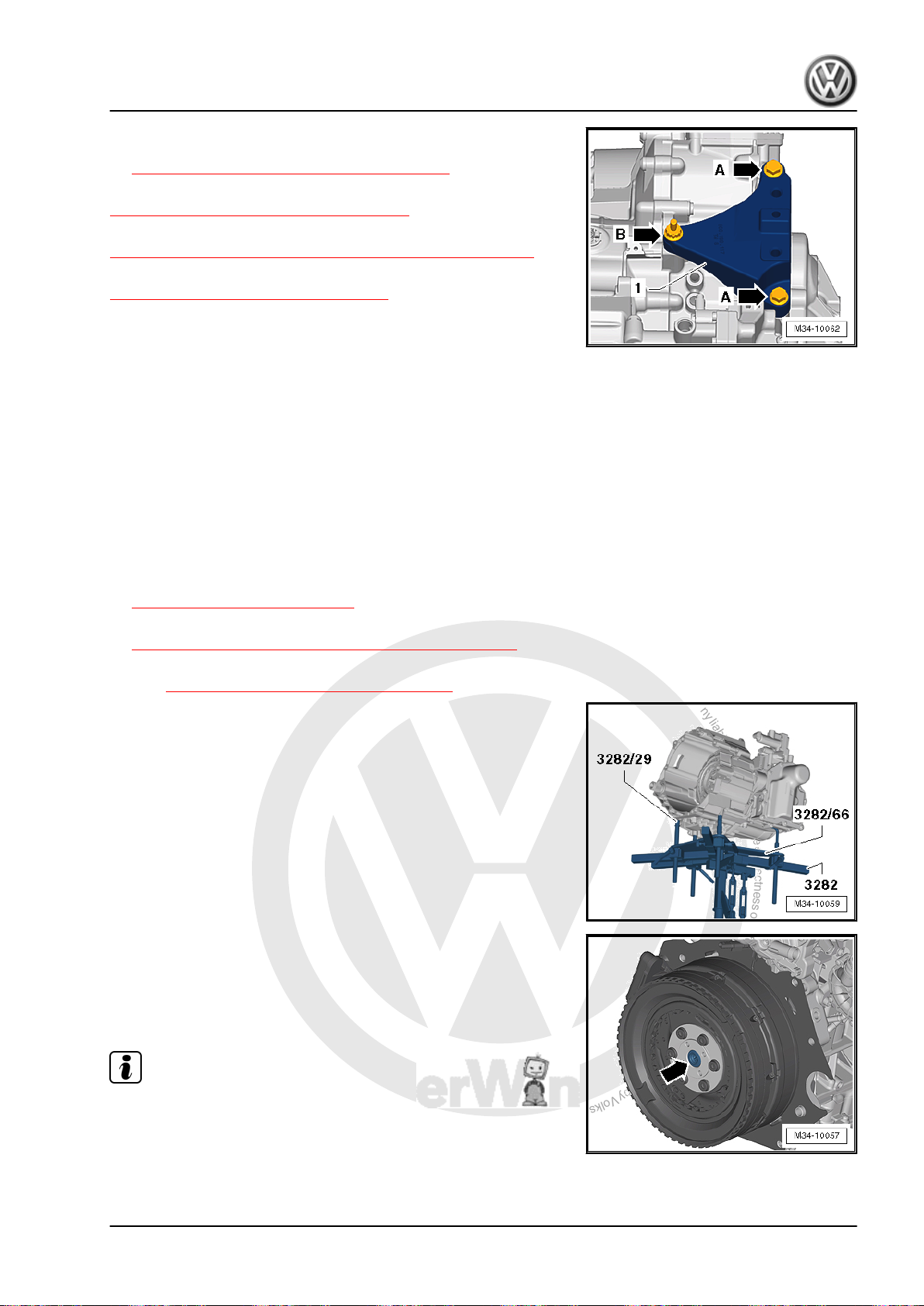
P
r
o
t
e
c
t
e
d
b
y
c
o
p
y
r
i
g
h
t
.
C
o
p
y
i
n
g
f
o
r
p
r
i
v
a
t
e
o
r
c
o
m
m
e
r
c
i
a
l
p
u
r
p
o
s
e
s
,
i
n
p
a
r
t
o
r
i
n
w
h
o
l
e
,
i
s
n
o
t
p
e
r
m
i
t
t
e
d
u
n
l
e
s
s
a
u
t
h
o
r
i
s
e
d
b
y
V
o
l
k
s
w
a
g
e
n
A
G
.
V
o
l
k
s
w
a
g
e
n
A
G
d
o
e
s
n
o
t
g
u
a
r
a
n
t
e
e
o
r
a
c
c
e
p
t
a
n
y
l
i
a
b
i
l
i
t
y
w
i
t
h
r
e
s
p
e
c
t
t
o
t
h
e
c
o
r
r
e
c
t
n
e
s
s
o
f
i
n
f
o
r
m
a
t
i
o
n
i
n
t
h
i
s
d
o
c
u
m
e
n
t
.
C
o
p
y
r
i
g
h
t
b
y
V
o
l
k
s
w
a
g
e
n
A
G
.
Direct Shift Gearbox - Edition 01.2016
– Remove the transmission bracket -1- from the transmission
-arrows A and B-, tightening specification. Refer to
⇒ “6.1 Overview - Subframe Mount”, page 103 .
Transmission, transporting. Refer to
⇒ “4 Transmission, Transporting”, page 100 .
Secure the transmission on the assembly stand. Refer to
⇒ “5 Securing on Engine and Transmission Holder”, page 102 .
Install the transmission. Refer to
⇒ “3.2 Transmission, Installing”, page 95 .
3.2 Transmission, Installing
– Install the transmission together with the engine. Refer to ⇒
Engine Mechanical, Fuel Injection and Ignition; Rep. Gr. 10 ;
Engine, Removing and Installing; Engine, Installing .
Attach the Transmission to the Engine As Follows:
• The Electro-Drive Drive Motor - V141- is attached to the en‐
gine.
• The Transmission Support - 3282- is installed in the Scissor
Lift Table - W12 Engine Support - VAS6131/2- on the Scissor
Lift Table - VAS6131- .
• Follow repair instructions. Refer to
⇒ “3 Repair Information”, page 6 .
• Refer to
⇒ “3.3 Transmission Tightening Specifications”, page 99
Refer to “Transmission, Removing” to get a list of the special tools
needed ⇒ “3.1 Transmission, Removing”, page 91 .
– Mount the transmission on the Transmission Support - 3282-
and secure it.
– Check if the alignment sleeves for centering the engine/trans‐
mission are in the cylinder block and insert them if they are
not.
– Check the needle bearing -arrow- in the Electro-Drive Drive
Motor - V141- . Replace it if necessary. Refer to ⇒ Engine
Mechanical, Fuel Injection and Ignition; Rep. Gr. 10 ; ElectroDrive Drive Motor - V141- , Removing from Engine and ⇒
Engine Mechanical, Fuel Injection and Ignition; Rep. Gr. 10 ;
Electro-Drive Drive Motor - V141- , Installing on Engine .
Note
The gears will no longer shift correctly if the needle bearing inside
the Electro-Drive Drive Motor - V141- is damaged.
Jetta Hybrid 2013 ➤
3. Transmission, Removing and Installing 95
Page 100
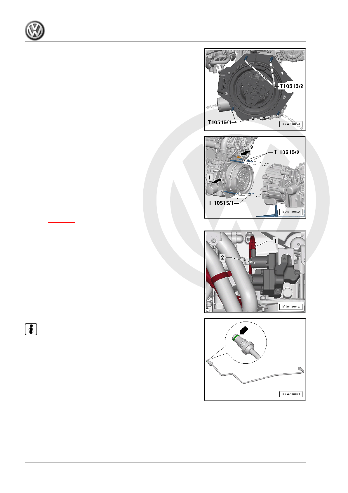
P
r
o
t
e
c
t
e
d
b
y
c
o
p
y
r
i
g
h
t
.
C
o
p
y
i
n
g
f
o
r
p
r
i
v
a
t
e
o
r
c
o
m
m
e
r
c
i
a
l
p
u
r
p
o
s
e
s
,
i
n
p
a
r
t
o
r
i
n
w
h
o
l
e
,
i
s
n
o
t
p
e
r
m
i
t
t
e
d
u
n
l
e
s
s
a
u
t
h
o
r
i
s
e
d
b
y
V
o
l
k
s
w
a
g
e
n
A
G
.
V
o
l
k
s
w
a
g
e
n
A
G
d
o
e
s
n
o
t
g
u
a
r
a
n
t
e
e
o
r
a
c
c
e
p
t
a
n
y
l
i
a
b
i
l
i
t
y
w
i
t
h
r
e
s
p
e
c
t
t
o
t
h
e
c
o
r
r
e
c
t
n
e
s
s
o
f
i
n
f
o
r
m
a
t
i
o
n
i
n
t
h
i
s
d
o
c
u
m
e
n
t
.
C
o
p
y
r
i
g
h
t
b
y
V
o
l
k
s
w
a
g
e
n
A
G
.
Jetta Hybrid 2013 ➤
Direct Shift Gearbox - Edition 01.2016
– Install the Centering Mandrel - T10515- into the engine, as
illustrated.
– Align the transmission with the engine and then carefully push
the transmission onto the engine. While doing this, turn the
spindle on the Transmission Support - 3282- to adjust the po‐
sition of the transmission.
• Be careful not to damage the connections -arrow 1- on the
Electro-Drive Drive Motor - V141- and on the Drive Motor
Temperature Sensor - G712- -arrow 2-.
• Guide the engine and transmission together by hand until the
entire surface of both flanges come into contact with one an‐
other.
Turn the crankshaft slightly if necessary.
– Attach the transmission to the engine and remove the Cen‐
tering Mandrel - T10515- from the engine.
– If the transmission was replaced: attach the cable bracket, the
transmission bracket and the bracket to the transmission. Re‐
fer to ⇒ page 94 .
– Connect the connector -1- to the valve -2- on the Mechatronic
and attach the wiring harness to the front bracket on the trans‐
mission.
Note
♦
Check the O-ring -arrow- on the hydraulic line for damage and
replace, if necessary. Refer to the Parts Catalog.
♦
The O-ring must appear green. It can be used with hydraulic
fluid. Do not use any other O-ring.
♦
Remove and dispose of the sealing plugs on the hydraulic line
as well as on the engine and valve block/Mechatronic just be‐
fore installation. The sealing plugs cannot be used again.
96 Rep. Gr.34 - Controls, Housing
 Loading...