

Van Air Systems PD-5 User Manual
APRIL 2000
P/N: 432-10001
INSTALLATION INSTRUCTIONS
PD-5
DIFFERENTIAL PRESSURE INDICATOR KIT
P/N: 84-10001
PRODUCT PURPOSE & FUNCTION:
Van Air's PD-5 Differential Pressure Indicators provide a visual indication for element
changeout. Designed for F200-55-1/2 thru F200-1000-3 filters, the PD-5 indicator needle will point to
red when a pressure drop of 10 PSID has occurred.
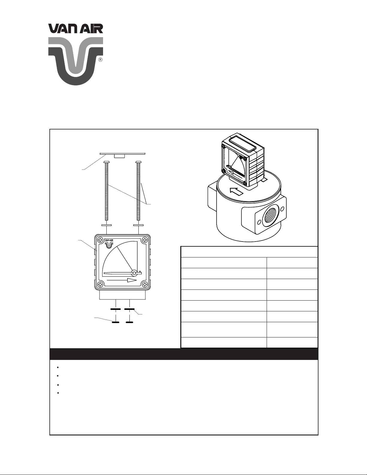
FIGURE 1 PD-5 KIT DETAILS
DUST
CAP
MOUNTING
SCREWS
PD-5
SPECIFICATIONS
BLANKING
PLATE
O-RING
RED
GREEN
Max Pressure 300 PSIG
INDICATOR
O-RING
MAXIMUM WORKING PRESSURE 300 PSIG
MAXIMUM TEMPERATURE 225°F
MATERIAL
BODY NYLON 6
LENSES POLYCARBONATE
SEALS (O-RINGS) BUNA-NITRILE
MAGNETS ANISOTROPIC
WEIGHT 3.4 OZ
WARNINGS
DO NOT INSTALL PD-5 TO EQUIPMENT WHILE UNDER PRESSURE.
FOLLOW INSTRUCTIONS FOR PD-5 WHEN INSTALLING INTO AIR SYSTEM.
DO NOT OPERATE UNIT ABOVE 300 PSIG.
A ZERO DIFFERENTIAL PRESSURE DOES NOT MEAN THAT THE FILTER IS
DEPRESSURIZED. NEVER REMOVE THE INDICATOR AND/OR FILTER
BOWL WITHOUT DEPRESSURIZING THE FILTER HOUSING AND ADJACENT PIPING. FAILURE TO DO SO MAY RESULT IN SERIOUS PERSONAL
INJURY AND/OR DAMAGE TO THE FILTER HOUSING AND/OR INDICATOR.
FERRITE
PRINTED IN THE USA ©2000 VAN AIR SYSTEMS INC.
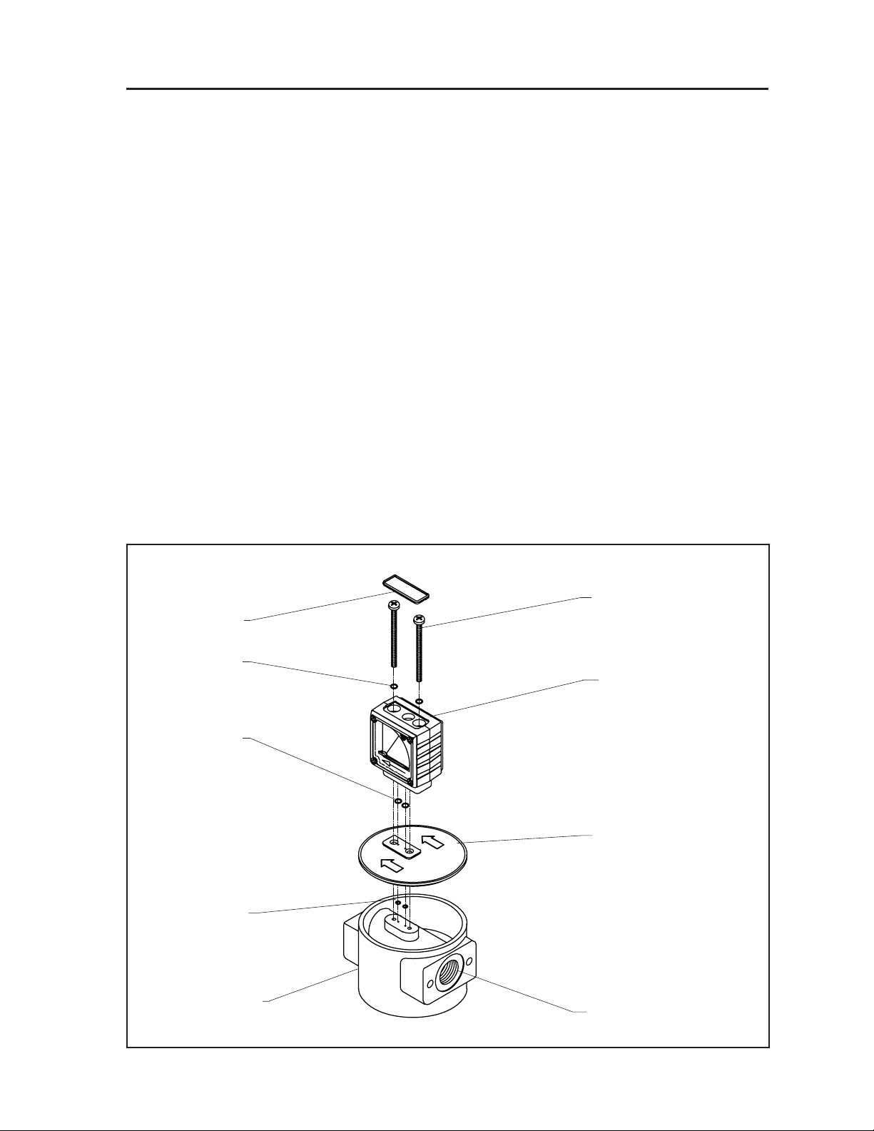
INSTALLATION (Reference Figure 2)
1.
Remove the blanking plate from the filter head by removing the (2) screws. Note the
orientation of the flow direction arrows so the plate may be reinstalled correctly.
2.
Turn blanking plate upside down. Remove the (2) small o-rings and discard.
3.
Drill a 3/32" hole in the center of each o-ring recess. NOTE: The PD-5 will not func-
tion if these holes are not drilled.
4.
Remove PD-5 from its packaging.
5.
Install (2) new blanking plate o-rings, included in the installation kit, into the recesses
on the bottom side of PD-5. NOTE: The blanking plate o-rings are slightly smaller
than the indicator o-rings.
6.
Remove dust cap from top of PD-5 so that mounting screws are exposed.
7.
Install the (2) indicator o-rings into the recesses on the bottom side of the indicator.
8.
Assemble and mount PD-5 and blanking plate to filter head as shown in Figure 2.
9.
Tighten indicator screws firmly. Do not overtighten as damage may occur to the
PD-5 and/or filter head.
10.
Reinstall dust cover on indicator.
FIGURE 2 INSTALLATION DETAILS
DUST COVER
WASHER
INDICATOR
O-RING
BLANKING
PLATE
O-RINGS
MOUNTING SCREWS
PD-5
BLANKING
PLATE
FILTER HEAD
INLET/OUTLET
CONNECTION
 Loading...